overlay thickness design using ndt methods zhong.pdf · overlay thickness design using ndt methods...
TRANSCRIPT

Overlay Thickness Design Using NDT Methods
Zhong Wu, Ph.D., P.E.LTRC
2009 Louisiana Transportation ConferenceFeb. 8-11, Baton Rouge

Outlines
BackgroundObjective and MethodologyOverlay Design ResultsAnalyze and Propose NDT Overlay
ProcedureCost/Benefit AnalysisSummary and Recommendation
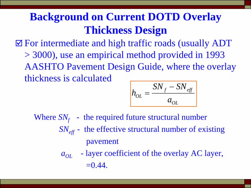
Background on Current DOTD Overlay Thickness Design
For intermediate and high traffic roads (usually ADT > 3000), use an empirical method provided in 1993 AASHTO Pavement Design Guide, where the overlay thickness is calculated
Where SNf - the required future structural number SNeff - the effective structural number of existing
pavementaOL - layer coefficient of the overlay AC layer,
=0.44.
OL
efffOL a
SNSNh
−=

Background (contd..)Current DOTD Overlay Thickness
Design SNeff = a1 × h1 + a2 × h2 + a3 × h3 …
ai – structural layer coefficient of existing layer i; Not tested.Determined by DOTD designlayer coefficient table
SNf = F (Mr, ESALs, ∆PSI, R, & So)
Layer 1: a1 h1
Layer 2: a2 h2
….
Subgrade: Mr
OL
efffOL a
SNSNh
−=
New AC Overlay: hOL
Mr - Not tested. Determined from DOTD Parish Map Mr-Table
AASHTO Flexible Pavement Design Equation
Exi
stin
g Pa
vem
ent

Background on Current DOTD Overlay Thickness Design (Contd..)
For low traffic roads, sometimes no overlay thickness design was performed; Instead, a typical 2-inch coplaning plus a few inches new
asphalt overlay are used as a typical overlay structure.
Due to no in-situ testing involved and its completely empirical nature, The current DOTD overlay design method usually provide
over or under designed overlay thickness
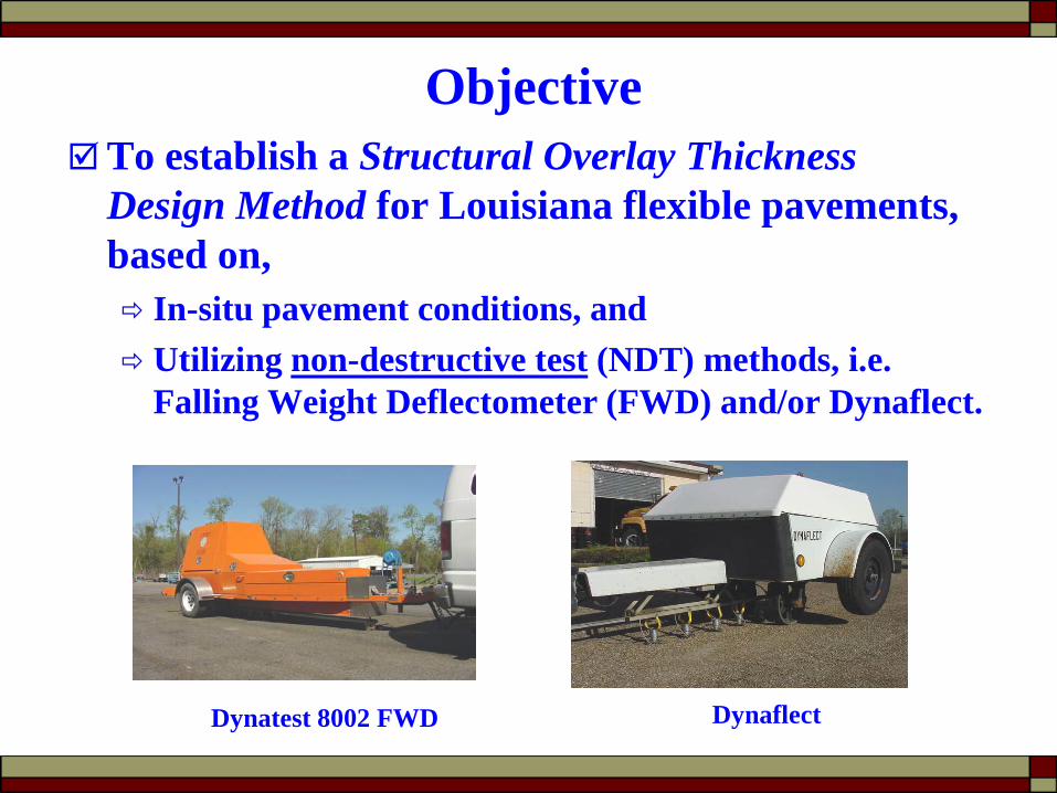
ObjectiveTo establish a Structural Overlay Thickness
Design Method for Louisiana flexible pavements, based on, In-situ pavement conditions, and Utilizing non-destructive test (NDT) methods, i.e.
Falling Weight Deflectometer (FWD) and/or Dynaflect.
Dynatest 8002 FWD Dynaflect
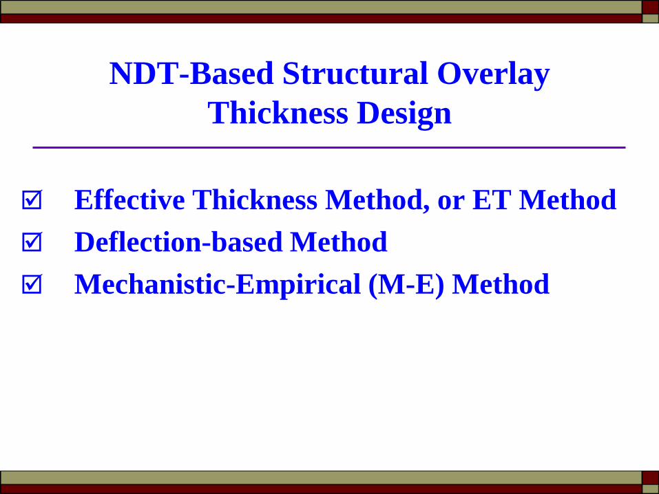
NDT-Based Structural Overlay Thickness Design
Effective Thickness Method, or ET Method Deflection-based Method Mechanistic-Empirical (M-E) Method
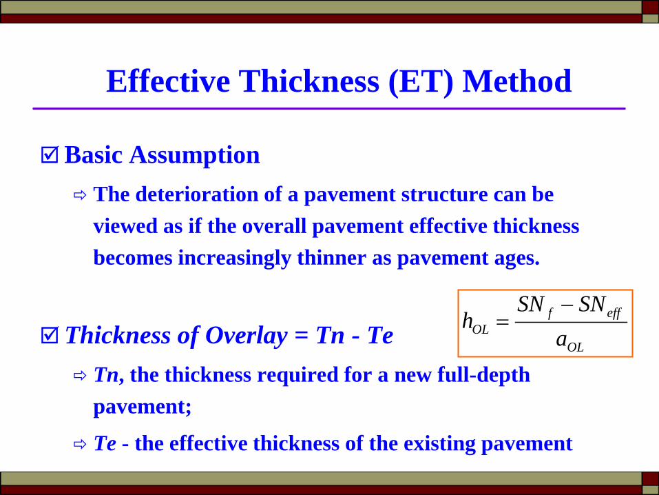
Effective Thickness (ET) Method
Basic Assumption The deterioration of a pavement structure can be
viewed as if the overall pavement effective thickness becomes increasingly thinner as pavement ages.
Thickness of Overlay = Tn - Te Tn, the thickness required for a new full-depth
pavement;
Te - the effective thickness of the existing pavement
OL
efffOL a
SNSNh
−=
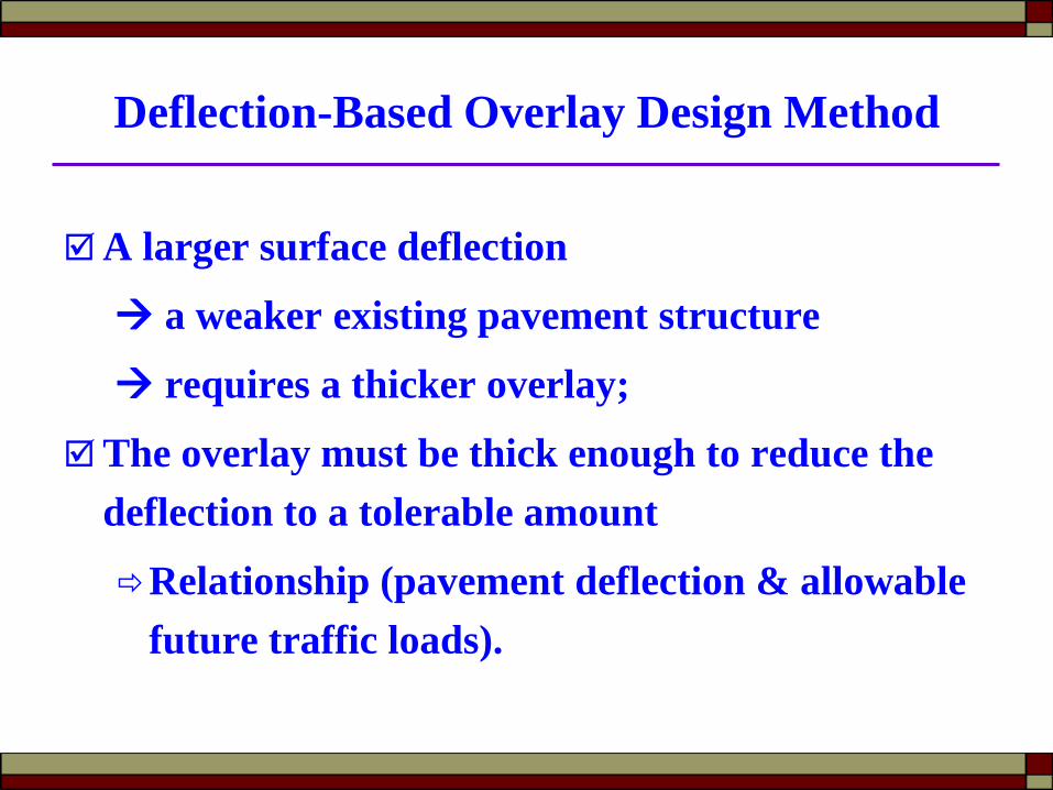
Deflection-Based Overlay Design Method
A larger surface deflection
a weaker existing pavement structure
requires a thicker overlay;
The overlay must be thick enough to reduce the deflection to a tolerable amount
Relationship (pavement deflection & allowable future traffic loads).

Mechanistic-Empirical (M-E) Method
Models pavements as multi-layered elastic or visco-elastic structure
Determine the critical stress, strain, or deflection by mechanistic methods using FWD backcalculated layer moduli
Predict resulting damages by empirical failure criteria, e.g. fatigue cracking, rutting.
E1, h1
E2, h2
E3, h3
Subgrade
εr
εv

NDT Overlay Design SurveyState Method Software
Arkansas Equivalent Thickness (ET) ROADHOG
Alabama ET (1993 AASHTO NDT) Spreadsheet program
Maryland ET (1993 AASHTO NDT) Spreadsheet program (VDOT)
Colorado ET (1993 AASHTO NDT) Darwin
Virginia ET (1993 AASHTO NDT) Spreadsheet program
California Deflection-based Design ManualNorth Carolina Deflection-based AI Spreadsheet program
South Carolina Deflection-based AI Spreadsheet program
Idaho M-E WinFlex
Mississippi M-E ELMOD5
Minnesota M-E MNPAVE
Oregon M-E /
Texas M-E FPS-19W
Washington M-E EVERPAVE
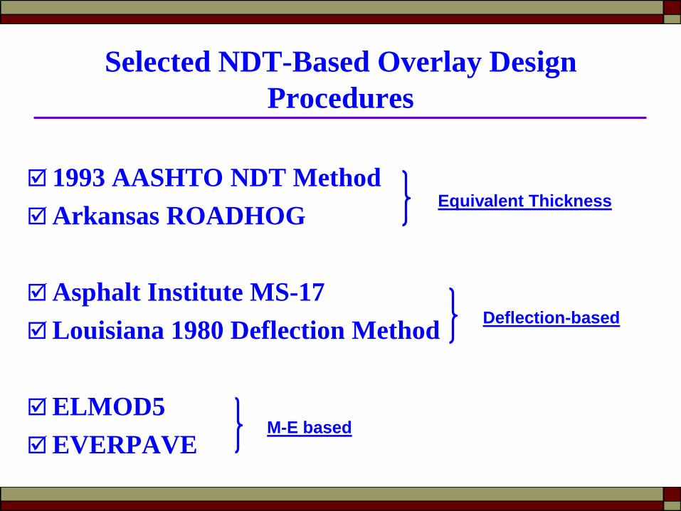
Selected NDT-Based Overlay Design Procedures
1993 AASHTO NDT MethodArkansas ROADHOG
Asphalt Institute MS-17Louisiana 1980 Deflection Method
ELMOD5EVERPAVE
Deflection-based
Equivalent Thickness
M-E based
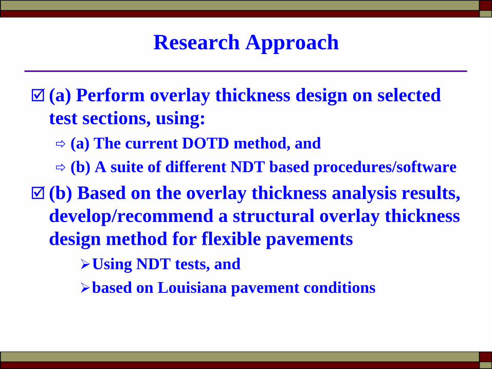
Research Approach
(a) Perform overlay thickness design on selected test sections, using: (a) The current DOTD method, and (b) A suite of different NDT based procedures/software
(b) Based on the overlay thickness analysis results, develop/recommend a structural overlay thickness design method for flexible pavements
Using NDT tests, and based on Louisiana pavement conditions
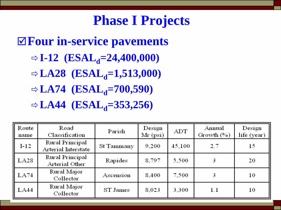
Phase I ProjectsFour in-service pavementsI-12 (ESALd=24,400,000)LA28 (ESALd=1,513,000)LA74 (ESALd=700,590)LA44 (ESALd=353,256)
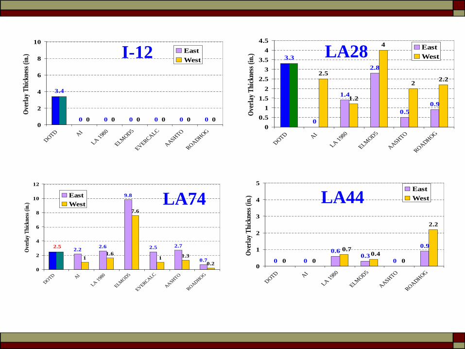
0 0 0 0 0 00 0 0 0 0 0
3.4
0
2
4
6
8
10
DOTD AI
LA 1980
ELMOD5
EVERCALC
AASHTO
ROADHOG
Over
lay T
hick
ness
(in.
) East
WestI-12
0
1.4
2.8
0.50.9
2.5
1.2
4
2 2.2
3.3
00.5
11.5
22.5
33.5
44.5
DOTD AI
LA 1980
ELMOD5
AASHTO
ROADHOG
Over
lay T
hick
ness
(in.
) East
West
2.2 2.6
9.8
2.5 2.7
0.711.6
7.6
1 1.30.2
2.5
0
2
4
6
8
10
12
DOTD AI
LA 1980
ELMOD5
EVERCALC
AASHTO
ROADHOG
Over
lay T
hick
ness
(in.)
EastWest
LA28
LA74
0 0
0.60.3
0
0.9
0 0 0
2.2
0.40.7
0
1
2
3
4
5
DOTD AI
LA 1980
ELMOD5
AASHTO
ROADHOG
Over
lay T
hick
ness
(in.
) East
WestLA44

DiscussionMixed-bag overlay thickness results obtained from
different methodsOne consensus result:DOTD method calls for 3.4” overlay on I-12However, all NDT-based design procedures call
zero inch overlayThis indicates thatOverlay thickness design should be based on in
situ pavement condition

Discussion (contd…)
Without further calibration and verification, none of those methods can be directly used in Louisiana:ROADHOG Delta D vs. SNeffAI: (δd) = 1.0363 (ESAL)-0.2438
EVERPAVE & ELMOD5 Fatigue/rutting equations, transfer functions
ObservationsAASHTO NDT procedure tends to provide a high
SNeff value for the existing pavements in Louisiana
0.0
2.0
4.0
6.0
8.0
10.0
12.0
14.0
16.0
SN (i
n.) FWD
Dynaflect
00.5
0
1.3
0
2
0
2.7
0
2
4
6
8
10
I-12 LA28 LA44 LA74
Ove
rlay
Thi
ckne
ss (i
n.)
EastWest
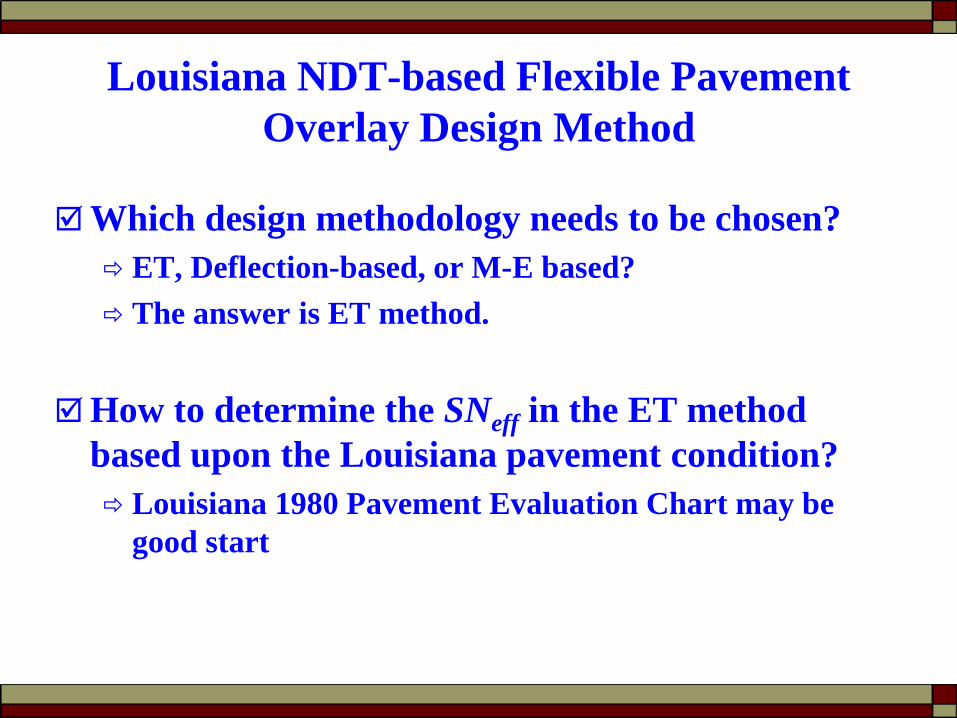
Louisiana NDT-based Flexible Pavement Overlay Design Method
Which design methodology needs to be chosen? ET, Deflection-based, or M-E based? The answer is ET method.
How to determine the SNeff in the ET method based upon the Louisiana pavement condition? Louisiana 1980 Pavement Evaluation Chart may be
good start

Louisiana Pavement Evaluation Chart
Kinchen and Temple (1980)
Using Dynaflect deflection, to determine SN of existing
pavements Subgrade
Modulus (Es)
SN values used in the Chart developmentEstimated by field cores including 26 failed pavementsBoth Es and SN represent LA Pavement condition. Still routinely used in pavement research.
Dynaflect Deflection (mils)
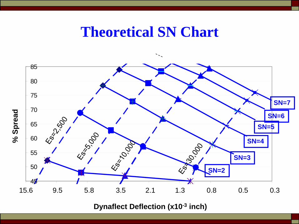
Theoretical SN Chart
45
50
55
60
65
70
75
80
85
-1.25-0.75-0.250.250.751.251.752.252.7515.6 9.5 5.8 3.5 2.1 1.3 0.8 0.5 0.3
Dynaflect Deflection (x10-3 inch)
% S
prea
d
SN=2
SN=5SN=6
SN=7
SN=3
SN=4
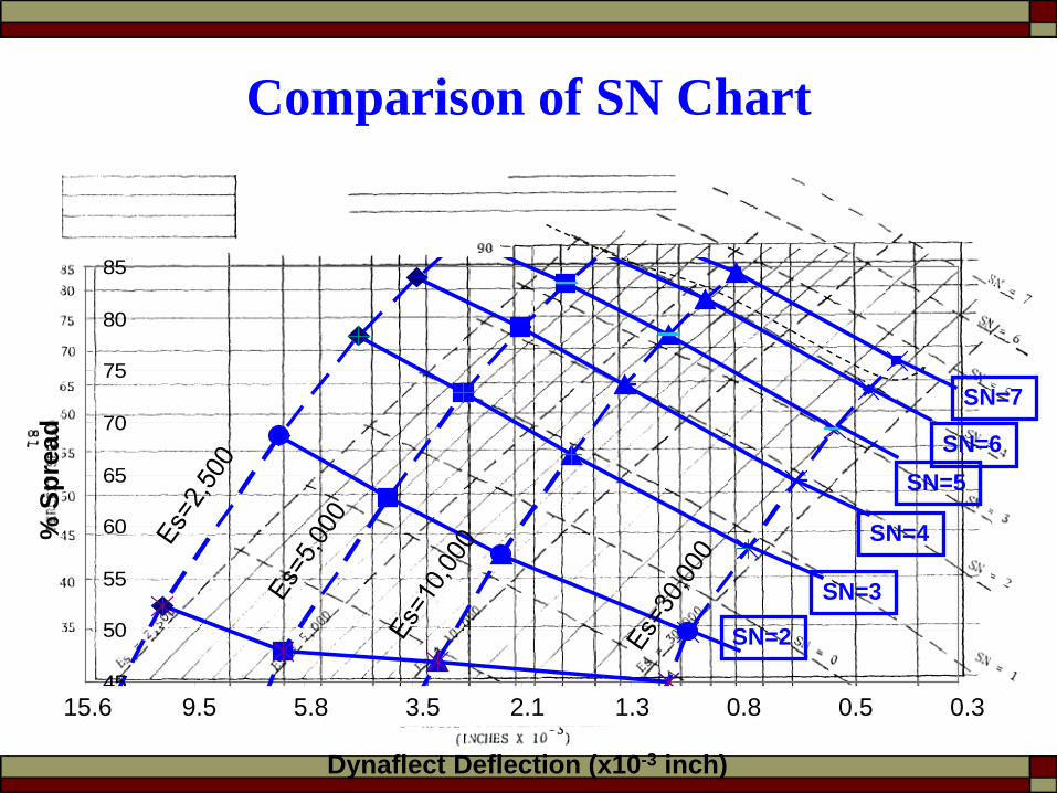
Comparison of SN Chart
45
50
55
60
65
70
75
80
85
-1.25-0.75-0.250.250.751.251.752.252.7515.6 9.5 5.8 3.5 2.1 1.3 0.8 0.5 0.3
Dynaflect Deflection (x10-3 inch)
% S
prea
d
SN=2
SN=5SN=6
SN=7
SN=3
SN=4
Summary
The Louisiana Pavement Evaluation Chart is theoretical sound;
Those shifting from theoretical results were based on local pavement conditions, e.g. using core determined SN values;
Therefore, the Louisiana Pavement Evaluation Chart is a locally calibrated, theoretical SN chart

SNDynaflect vs. SNFWD
Note: Data from 13 projects and total 271 test points
Y=2.58ln(x) – 0.77R2=0.92
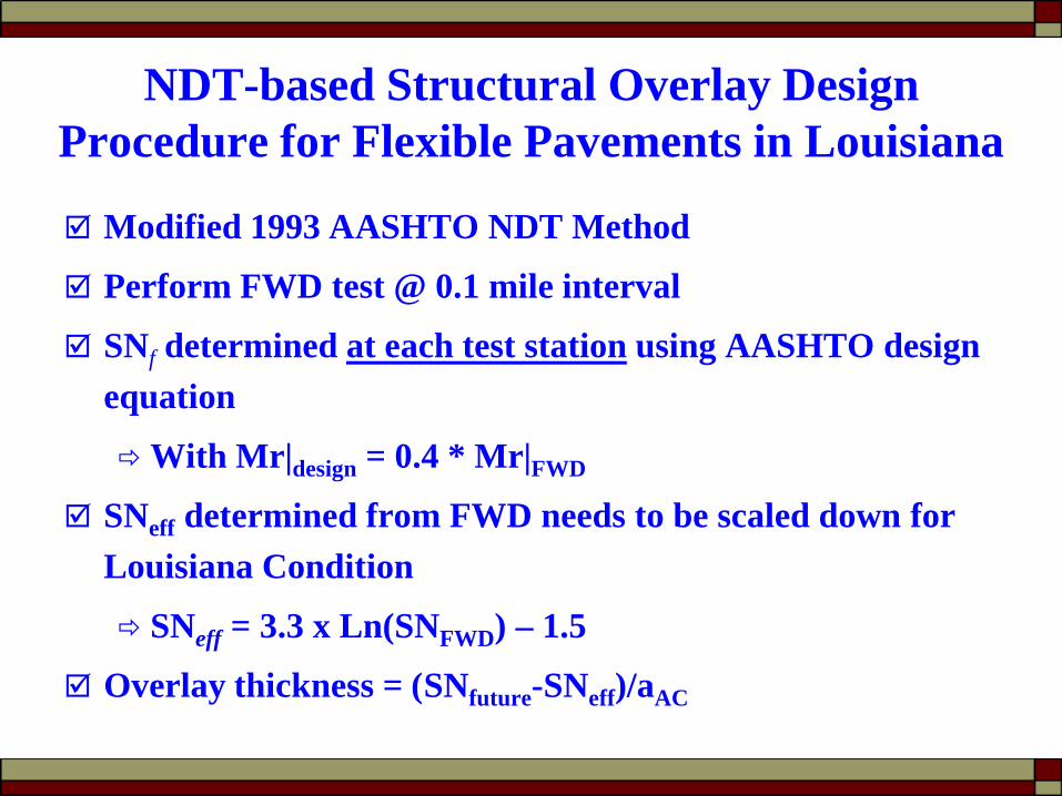
NDT-based Structural Overlay Design Procedure for Flexible Pavements in Louisiana
Modified 1993 AASHTO NDT Method
Perform FWD test @ 0.1 mile interval
SNf determined at each test station using AASHTO design equation
With Mr|design = 0.4 * Mr|FWD
SNeff determined from FWD needs to be scaled down for Louisiana Condition
SNeff = 3.3 x Ln(SNFWD) – 1.5
Overlay thickness = (SNfuture-SNeff)/aAC

Phase II Projects

Phase II Project List
Except three widening projects - LA 143, US165 and LA1025, all other projects had a overlay thickness design.

Design Thickness Difference(Current DOTD Method – Proposed Method)
-2
-1.5
-1
-0.5
0
0.5
1
1.5
2
LA 173 LA 527 LA 137 LA 27 LA 101 US 84 US 165 LA 15 LA 28 LA3127
LA 37
Dif
fere
nce
in O
verl
ay T
hick
ness
(i
NB/EBSB/WB
“+” Over-design “-” Under-design
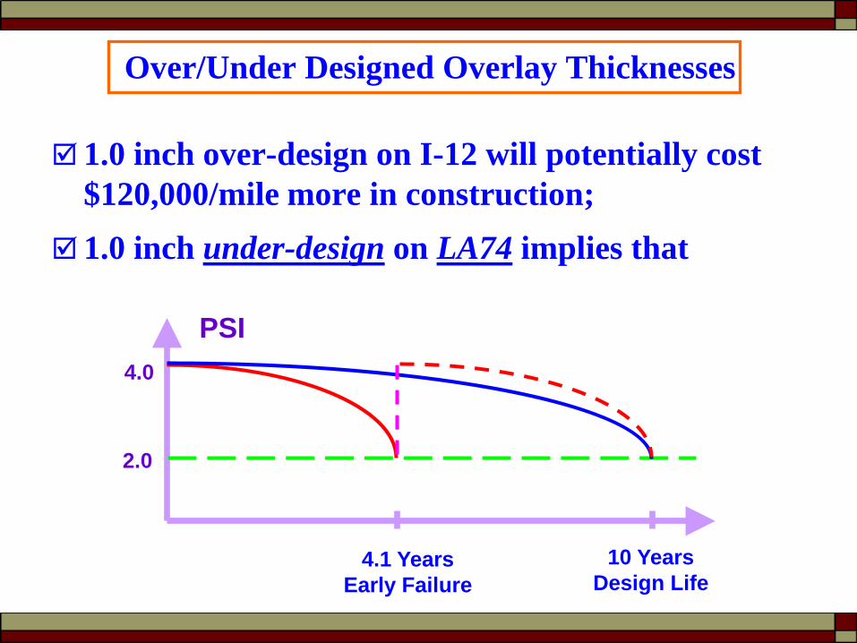
Over/Under Designed Overlay Thicknesses
1.0 inch over-design on I-12 will potentially cost $120,000/mile more in construction;
1.0 inch under-design on LA74 implies that
4.1 YearsEarly Failure
10 YearsDesign Life
PSI4.0
2.0

Cost/Benefit AnalysisFor over-designed projects
The average construction cost saving be $427,300 / project The average length of 6.9 mi Saving $62,000 /mile.
For under-designed projects The average predicted pavement life be 5.8 yr; Due to a faster deterioration
Annual preventive maintenance/repair costs will be increasedNeed another overlay at the end of lifeMuch greater costs to the property manager in the long run
The average life-time cost saving be $230,600 / project The average length of 7.2 mi Saving $32,000 /mile.

Recommendations
Recommend the proposed method to be used by DOTD before full implementation of the new M-E design guide.
A computer program for the proposed overlay design procedure has been developed.

Thank you!