overload safety couplings - zero-max a/s · 2018-12-12 · mounting options mounting options 3...
TRANSCRIPT
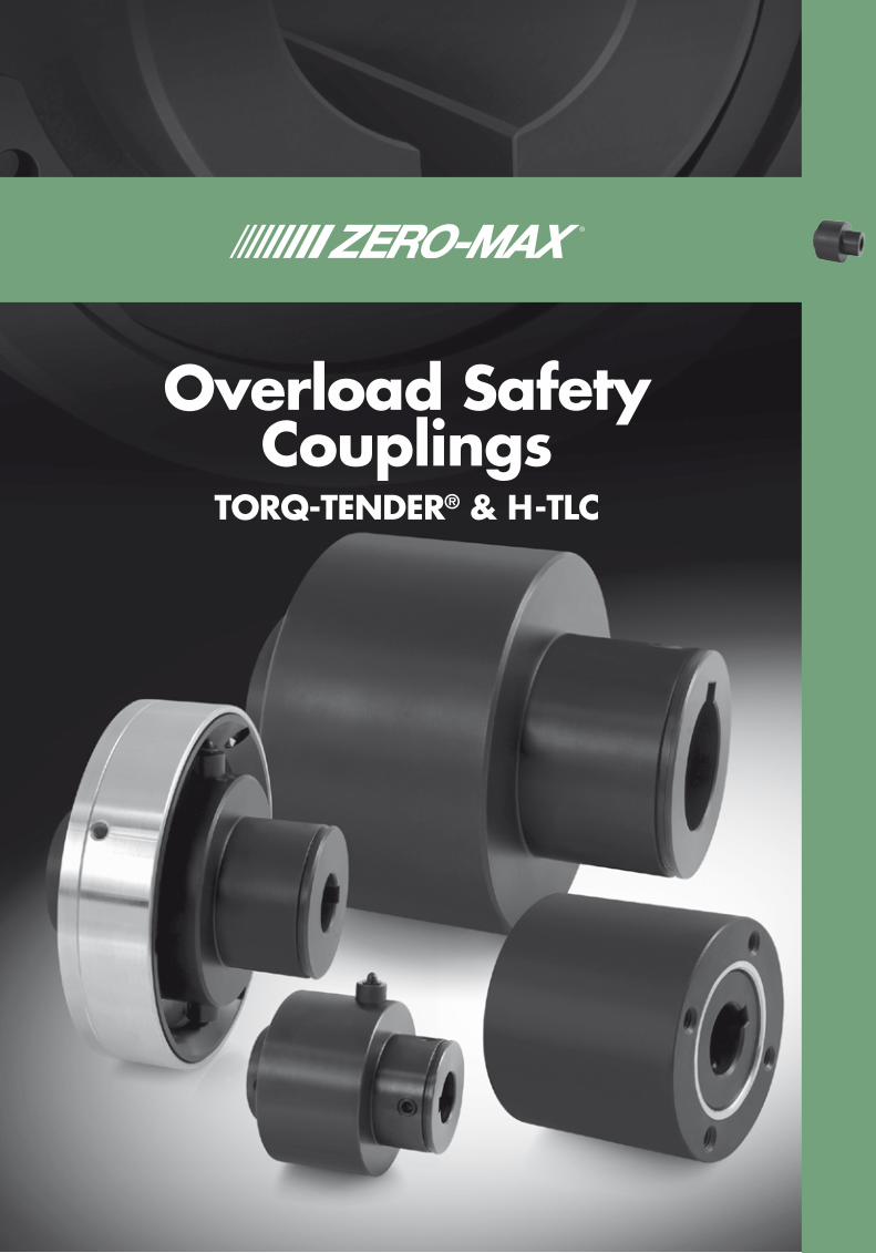
Torq-Tender® & H-TLC
Overload Safety Couplings
Overload SafetyCouplings
TORQ-TENDER® & H-TLC
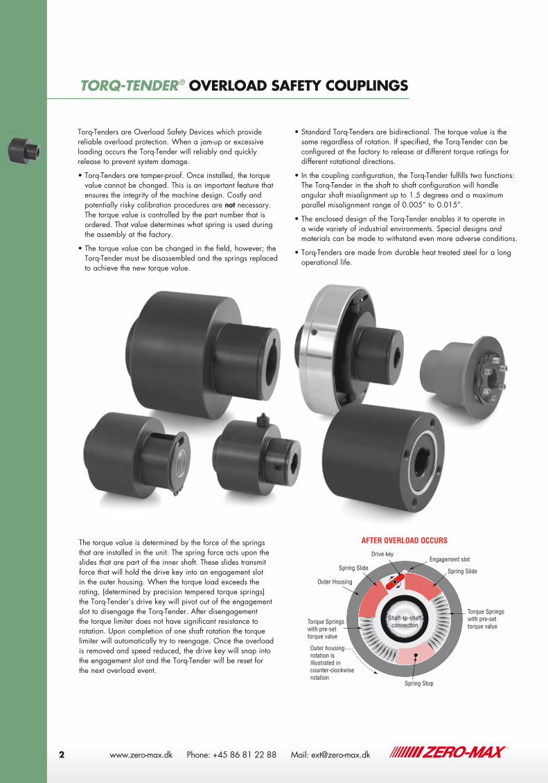
The torque value is determined by the force of the springs that are installed in the unit. The spring force acts upon the slides that are part of the inner shaft. These slides transmit force that will hold the drive key into an engagement slot in the outer housing. When the torque load exceeds the rating, (determined by precision tempered torque springs) the Torq-Tender’s drive key will pivot out of the engagement slot to disengage the Torq-Tender. After disengagement the torque limiter does not have significant resistance to rotation. Upon completion of one shaft rotation the torque limiter will automatically try to reengage. Once the overload is removed and speed reduced, the drive key will snap into the engagement slot and the Torq-Tender will be reset for the next overload event.
Torq-Tenders are Overload Safety Devices which provide reliable overload protection. When a jam-up or excessive loading occurs the Torq-Tender will reliably and quickly release to prevent system damage.
• Torq-Tenders are tamper-proof. Once installed, the torque value cannot be changed. This is an important feature that ensures the integrity of the machine design. Costly and potentially risky calibration procedures are not necessary. The torque value is controlled by the part number that is ordered. That value determines what spring is used during the assembly at the factory.
• The torque value can be changed in the field, however; the Torq-Tender must be disassembled and the springs replaced to achieve the new torque value.
• Standard Torq-Tenders are bidirectional. The torque value is the same regardless of rotation. If specified, the Torq-Tender can be configured at the factory to release at different torque ratings for different rotational directions.
• In the coupling configuration, the Torq-Tender fulfills two functions: The Torq-Tender in the shaft to shaft configuration will handle angular shaft misalignment up to 1.5 degrees and a maximum parallel misalignment range of 0.005” to 0.015”.
• The enclosed design of the Torq-Tender enables it to operate in a wide variety of industrial environments. Special designs and materials can be made to withstand even more adverse conditions.
• Torq-Tenders are made from durable heat treated steel for a long operational life.
As Torq-Tender reaches pre-set torque rating, Drive key pivots out of Engagement slot, thus releasing outer housing connection.
Drive key (pin)
Spring Slide
Engagement slot
Spring Slide
Torque Springs with pre-set torque value
Torque Springs with pre-set torque value
Spring Stop
Outer Housing
Drive key
Spring Slide
Engagement slotSpring Slide
Torque Springs with pre-set torque value
Torque Springswith pre-set torque value
Spring Stop
Outer Housing
Outer housing rotation is Illustrated in counter-clockwiserotation
Outer housing rotation is Illustrated in counter-clockwise rotation
Simulation shown here is for a Zero-Max Torq-Tender Overload Safety Coupling. Model simulated is a shaft-to-shaft mount TYPE C.
BEFORE OVERLOAD OCCURS AFTER OVERLOAD OCCURS
Shaft-to-shaftconnection
Shaft-to-shaftconnection
TORQ-TENDER® OVERLOAD SAFETY COUPLINGS
2 www.zero-max.com Phone 800.533.1731 763.546.4300 Fax 763.546.8260
TORQ-TENDER® OVERLOAD SAFETY COUPLINGS
www.zero-max.dk Phone: +45 86 81 22 88 Mail: [email protected]

MOUNTING OPTIONSMOUNTING OPTIONS
3
Through Shaft Mount – Type B The Through Shaft Mount is intended to have a shaft pass though the full length of the Torq-Tender. A component such as a sprocket or sheave is mounted externally on the Torq-Tender. When an overload occurs, the driven component will stop rotating while the driving component (shaft, pulley, sprocket etc.) will continue to rotate. A sleeve bearing (bronze bushing) is an integral part of the design that supports the side load created by the mounted component and allowing the housing to rotate on the shaft during an overload. Note: An external keyway in the hub and retaining ring is standard on this design.
Shaft-To-Shaft Mount – Type C The shaft to shaft mount option allows the Torq-Tender to function as a shaft coupling and a torque limiter.
End of Shaft Mount – Type JFThe End of Shaft Mount-Type JF torque limiter is used where you have limited or reduced shaft length available. The Type JF model allows you to face mount a plate style sprocket or pulley to the torque limiter using bolts. Either the shaft or the mounted component can be used to drive the load. Since the mounted component is located very close to the bearing supports the overhung load is reduced.
End of Shaft Mount – Type J The End of Shaft Mount Type J offers the same benefits as the JF model. The type J model is designed to mount type B or C style hubs for sprockets and pulleys. This model is available in 2 sizes: TT2J and TT3J.
End of Shaft Mount – Type S The End of Shaft Mount Type S is used in applications where the drive shaft is not long enough to reach the radial load. The type S model is designed to mount a type B or C style hub for sprockets and pulleys. This model is available in 4 sizes: TT1X-S, TT2-S, TT2X-S, and TT3-S.
www.zero-max.com
3D CAD Downloads
3D CAD Downloads
www.zero-max.dk Phone: +45 86 81 22 88 Mail: [email protected] 3

4 www.zero-max.com Phone 800.533.1731 763.546.4300 Fax 763.546.8260
TORQ-TENDER® OVERLOAD SAFETY COUPLINGS
See chart on page 52 for bore sizes.
D= Maximum key length
Torq-TenderThrough Shaft – Type B
Torq-Tender Models
TT1X TT2 TT2X TT3 TT3TAN TT3X TT4X
AINCH (MM)
1.562 (39.7)
2.165 (55)
2.500 (63.5)
3.000 (76.2)
3.000 (76.2)
3.625 (92.1)
4.625 (117.5)
BINCH (MM)
0.875 (22.2)
1.250 (31.7)
1.500 (38.1)
1.750 (44.4)
1.750 (44.4)
2.250 (57.1)
3.000 (76.2)
DINCH (MM)
1.140 (29)
1.540 (39.1)
1.805 (45.8)
2.100 (53.3)
3.312 (84.1)
3.080 (78.2)
3.715 (94.4)
GINCH (MM)
1.000 (25.4)
1.375 (34.9)
1.625 (41.3)
1.750 (44.4)
1.750 (44.4)
2.500 (63.5)
3.000 (76.2)
HINCH (MM)
0.135 (3.4)
0.250 (6.4)
0.312 (8)0.312 (8)0.312
(8)0.420 (10.7)
0.400 (10.2)
IINCH (MM)
0.205 (5.2)
0.365 (9.3)
0.455 (11.6)
0.470 (11.9)
0.500 (12.7)
0.555 (14.1)
0.570 (14.5)
JINCH (MM)
1.000 (25.4)
1.300 (33)
1.500 (38.1)
1.812 (46)
3.035 (77.1)
2.750 (69.8)
3.500 (89)
KINCH (MM)
1.800 (45.7)
2.420 (61.5)
2.950 (75)
3.470 (88.1)
4.710 (119.6)
4.550 (115.6)
5.400 (137.2)
LINCH (MM)
0.600 (15.2)
0.750 (19)
1.000 (25.4)
1.187 (30.1)
1.187 (30.1)
1.250 (31.7)
1.330 (33.8)
NINCH (MM)
0.500 (12.7)
0.625 (15.9)
0.875 (22.2)
1.062 (27)
1.062 (27)
1.080 (27.4)
1.125 (28.6)
OINCH (MM)
0.250 (6.3)
0.312 (8)
0.375 (9.5)
0.375 (9.5)
0.375 (9.5)
0.625 (15.9)
0.750 (19)
Torq-TenderShaft to Shaft – Type CTorq-Tender
ModelsTT1X TT2 TT2X TT3 TT3TAN TT3X TT4X
AINCH (MM)
1.562 (39.7)
2.165 (55)
2.500 (63.5)
3.000 (76.2)
3.000 (76.2)
3.625 (92.1)
4.625 (117.5)
BINCH (MM)
0.875 (22.2)
1.250 (31.7)
1.500 (38.1)
1.750 (44.4)
1.750 (44.4)
2.250 (57.1)
3.000 (76.2)
DINCH (MM)
1.140 (29)
1.540 (39.1)
1.805 (45.8)
2.100 (53.3)
3.312 (84.1)
3.080 (78.2)
3.715 (94.4)
EINCH (MM)
0.630 (16)
0.820 (20.8)
1.110 (28.2)
1.330 (33.8)
1.312 (33.3)
1.420 (36.1)
1.640 (41.6)
GINCH (MM)
1.000 (25.4)
1.375 (34.9)
1.625 (41.3)
1.750 (44.4)
1.750 (44.4)
2.500 (63.5)
3.000 (76.2)
HINCH (MM)
0.135 (3.4)
0.250 (6.4)
0.312 (8)
0.312 (8)
0.312 (8)
0.420 (10.7)
0.400 (10.2)
IINCH (MM)
0.205 (5.2)
0.365 (9.3)
0.455 (11.6)
0.470 (11.9)
0.500 (12.7)
0.555 (14.1)
0.570 (14.5)
JINCH (MM)
1.000 (25.4)
1.300 (33)
1.500 (38.1)
1.812 (46)
3.035 (77.1)
2.750 (69.8)
3.500 (89)
KINCH (MM)
1.800 (45.7)
2.420 (61.5)
2.950 (75)
3.470 (88.1)
4.710 (119.6)
4.550 (115.6)
5.400 (137.2)
LINCH (MM)
0.600 (15.2)
0.750 (19)
1.000 (25.4)
1.187 (30.1)
1.187 (30.1)
1.250 (31.7)
1.330 (33.8)
MINCH (MM)
0.218 (5.5)
0.312 (8)0.312
(8)0.375 (9.5)
0.375 (9.5)
0.420 (10.7)
0.500 (12.7)
F BORE
A
C BORE
H M
K
D E
I J L
G B F BOREC BORE
F BORE
A
C BORE
H M
K
D E
I J L
G B F BOREC BORE
F BORE
A
C BORE
H M
K
D E
I J L
G B F BOREC BORE
H
A
J I L
*SLEEVE BEARING
K
B
D
O
G
N
C BORE
H
A
J I L
*SLEEVE BEARING
K
B
D
O
G
N
C BORE
H
A
J I L
*SLEEVE BEARING
K
B
D
O
G
N
C BORE
* The ID of the sleeve bearing will be sized to match the C Bore. When ordering this option, only specify one bore.
TORQ-TENDER® OVERLOAD SAFETY COUPLINGS
www.zero-max.dk Phone: +45 86 81 22 88 Mail: [email protected]

TORQ-TENDER® OVERLOAD SAFETY COUPLINGS
5
See chart on page 52 for bore sizes.
Torq-TenderEnd of Shaft – Type JFTorq-Tender
Models TT1XJF TT2JF TT2XJF TT3JF TT3XJF TT4XJF
AINCH (MM)
1.562 (39.7)
2.165 (55)
2.500 (63.5)
3.000 (76.2)
3.625 (92.1)
4.625 (117.5)
KINCH (MM)
1.500 (38.1)
1.885 (47.9)
2.250 (57.1)
2.560 (65)
3.550 (90.2)
4.375 (111.1)
MINCH (MM)
0.187 (4.7)
0.282 (7.2)
0.325 (8.2)
0.370 (9.4)
0.400 (10.2)
0.375 (9.5)
PINCH (MM)
0.875 (22.2)
1.200 (30.5)
1.500 (38.1)
1.625 (41.3)
2.125 (54)
2.625 (66.7)
QINCH (MM)
1.250 (31.7)
1.750 (44.4)
2.000 (50.8)
2.375 (60.3)
3.000 (76.2)
4.000 (101.6)
R INCH10-32
X 0.25DP10-32
X 0.37DP1/4-20
X 0.50DP5/16-18
X 0.56DP5/16-18
X 0.56DP3/8-16
X 0.75DP
A
R (THREAD SIZE)
M P
K C BORE
Q
A
R (THREAD SIZE)
M P
K C BORE
Q
Torq-TenderEnd of Shaft – Type STorq-Tender
ModelsTT1X TT2 TT2X TT3
AINCH (MM)
1.562 (39.7)
2.165 (55)
2.500 (63.5)
3.000 (76.2)
BINCH (MM)
0.875 (22.2)
1.250 (31.7)
1.500 (38.1)
1.750 (44.4)
DINCH (MM)
1.140 (29)
1.540 (39.1)
1.805 (45.8)
2.100 (53.3)
GINCH (MM)
1.000 (25.4)
1.375 (34.9)
1.625 (41.3)
1.750 (44.4)
HINCH (MM)
0.135 (3.4)
0.250 (6.4)
0.312 (8)
0.312 (8)
IINCH (MM)
0.205 (5.2)
0.365 (9.3)
0.455 (11.6)
0.470 (11.9)
JINCH (MM)
1.000 (25.4)
1.300 (33)
1.500 (38.1)
1.812 (46)
KINCH (MM)
1.800 (45.7)
2.420 (61.5)
2.950 (75)
3.470 (88.1)
LINCH (MM)
0.600 (15.2)
0.750 (19)
1.000 (25.4)
1.187 (30.1)
NINCH (MM)
0.500 (12.7)
0.625 (15.9)
0.875 (22.2)
1.062 (27)
OINCH (MN)
0.250 (6.3)
0.312 (8)
0.375 (9.5)
0.375 (9.5)
Torq-TenderEnd of Shaft – Type JTorq-Tender
Models TT2 TT3
AINCH (MM)
2.165 (55)
3.00 (76.2)
GINCH (MM)
1.625 (41.3)
2.250 (57.15)
JINCH (MM)
1.950 (49.5)
3.060 (77.7)
KINCH (MM)
2.110 (53.6)
3.294 (83.7)
LINCH (MM)
0.750 (19)
1.188 (30.2)
NINCH (MM)
0.625 (15.9)
1.03 (26.2)
OINCH (MM)
0.312 (7.9)
0.375 (9.5)
A
H I J L
N
B O
G
D
C BORE
K
A
H I J L
N
B O
G
D
C BORE
K
A
H I J L
N
B O
G
D
C BORE
K
A
K
L
C BORE
O
N
J
G
A
K
L
C BORE
O
N
J
G
A
K
L
C BORE
O
N
J
G
A
R (THREAD SIZE)
M P
K C BORE
Q
www.zero-max.dk Phone: +45 86 81 22 88 Mail: [email protected] 5
6 www.zero-max.com Phone 800.533.1731 763.546.4300 Fax 763.546.8260
TORQ-TENDER® OVERLOAD SAFETY COUPLINGS
J WITH ACT. PIN JF WITH ACT. PIN
6-6-09 TOM F.
SHAFT TO SHAFT
SHAFT TO SHAFTW/ACT. DISC J WITH ACT. DISC JF WITH ACT. DISC
TT-CATALOG
A
K
S
W U T
A
K
SW
UT
GB G A
S
K
Q
R
WU
T
W
U T
BAX
Z YK
G
L
N
GAX
K
LN
Y ZZI
Q AAX
Y ZZ1
K
R
Z1
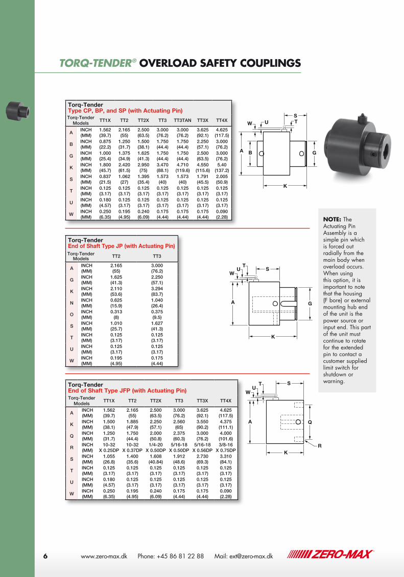
Torq-TenderType CP, BP, and SP (with Actuating Pin)Torq-Tender
ModelsTT1X TT2 TT2X TT3 TT3TAN TT3X TT4X
AINCH (MM)
1.562 (39.7)
2.165 (55)
2.500 (63.5)
3.000 (76.2)
3.000 (76.2)
3.625 (92.1)
4.625 (117.5)
BINCH (MM)
0.875 (22.2)
1.250 (31.7)
1.500 (38.1)
1.750 (44.4)
1.750 (44.4)
2.250 (57.1)
3.000 (76.2)
GINCH (MM)
1.000 (25.4)
1.375 (34.9)
1.625 (41.3)
1.750 (44.4)
1.750 (44.4)
2.500 (63.5)
3.000 (76.2)
KINCH (MM)
1.800 (45.7)
2.420 (61.5)
2.950 (75)
3.470 (88.1)
4.710 (119.6)
4.550 (115.6)
5.40 (137.2)
SINCH (MM)
0.837 (21.5)
1.062 (27)
1.395 (35.4)
1.573 (40)
1.573 (40)
1.791 (45.5)
2.005 (50.9)
TINCH (MM)
0.125 (3.17)
0.125 (3.17)
0.125 (3.17)
0.125 (3.17)
0.125 (3.17)
0.125 (3.17)
0.125 (3.17)
UINCH (MM)
0.180 (4.57)
0.125 (3.17)
0.125 (3.17)
0.125 (3.17)
0.125 (3.17)
0.125 (3.17)
0.125 (3.17)
WINCH (MM)
0.250 (6.35)
0.195 (4.95)
0.240 (6.09)
0.175 (4.44)
0.175 (4.44)
0.175 (4.44)
0.090 (2.28)
Torq-Tender End of Shaft Type JFP (with Actuating Pin)Torq-Tender
ModelsTT1X TT2 TT2X TT3 TT3X TT4X
AINCH (MM)
1.562 (39.7)
2.165 (55)
2.500 (63.5)
3.000 (76.2)
3.625 (92.1)
4.625 (117.5)
KINCH (MM)
1.500 (38.1)
1.885 (47.9)
2.250 (57.1)
2.560 (65)
3.550 (90.2)
4.375 (111.1)
QINCH (MM)
1.250 (31.7)
1.750 (44.4)
2.000 (50.8)
2.375 (60.3)
3.000 (76.2)
4.000 (101.6)
RINCH (MM)
10-32 X 0.25DP
10-32 X 0.37DP
1/4-20 X 0.50DP
5/16-18 X 0.50DP
5/16-18 X 0.56DP
3/8-16 X 0.75DP
SINCH (MM)
1.055 (26.8)
1.400 (35.6)
1.608 (40.84)
1.912 (48.6)
2.730 (69.3)
3.310 (84.1)
TINCH (MM)
0.125 (3.17)
0.125 (3.17)
0.125 (3.17)
0.125 (3.17)
0.125 (3.17)
0.125 (3.17)
UINCH (MM)
0.180 (4.57)
0.125 (3.17)
0.125 (3.17)
0.125 (3.17)
0.125 (3.17)
0.125 (3.17)
WINCH (MM)
0.250 (6.35)
0.195 (4.95)
0.240 (6.09)
0.175 (4.44)
0.175 (4.44)
0.090 (2.28)
Torq-Tender End of Shaft Type JP (with Actuating Pin)Torq-Tender
Models TT2 TT3
AINCH (MM)
2.165 (55)
3.000 (76.2)
GINCH (MM)
1.625 (41.3)
2.250 (57.1)
KINCH (MM)
2.110 (53.6)
3.294 (83.7)
NINCH (MM)
0.625 (15.9)
1.040 (26.4)
OINCH (MM)
0.313 (8)
0.375 (9.5)
SINCH (MM)
1.010 (25.7)
1.627 (41.3)
TINCH (MM)
0.125 (3.17)
0.125 (3.17)
UINCH (MM)
0.125 (3.17)
0.125 (3.17)
WINCH (MM)
0.195 (4.95)
0.175 (4.44)
J WITH ACT. PIN JF WITH ACT. PIN
6-6-09 TOM F.
SHAFT TO SHAFT
SHAFT TO SHAFTW/ACT. DISC J WITH ACT. DISC JF WITH ACT. DISC
TT-CATALOG
A
K
S
W U T
A
K
SW
UT
GB G A
S
K
Q
R
WU
T
W
U T
BAX
Z YK
G
L
N
GAX
K
LN
Y ZZI
Q AAX
Y ZZ1
K
R
Z1
J WITH ACT. PIN JF WITH ACT. PIN
6-6-09 TOM F.
SHAFT TO SHAFT
SHAFT TO SHAFTW/ACT. DISC J WITH ACT. DISC JF WITH ACT. DISC
TT-CATALOG
A
K
S
W U T
A
K
SW
UT
GB G A
S
K
Q
R
WU
T
W
U T
BAX
Z YK
G
L
N
GAX
K
LN
Y ZZI
Q AAX
Y ZZ1
K
R
Z1
NOTE: The Actuating Pin Assembly is a simple pin which is forced out radially from the main body when overload occurs. When using this option, it is important to note that the housing (F bore) or external mounting hub end of the unit is the power source or input end. This part of the unit must continue to rotate for the extended pin to contact a customer supplied limit switch for shutdown or warning.
TORQ-TENDER® OVERLOAD SAFETY COUPLINGS
www.zero-max.dk Phone: +45 86 81 22 88 Mail: [email protected]

TORQ-TENDER® OVERLOAD SAFETY COUPLINGS
7
Torq-TenderType CD, BD, and SD (with Actuating Disc)Torq-Tender
ModelsTT1X TT2 TT2X TT3 TT3TAN TT3X TT4X
AINCH (MM)
1.562 (39.7)
2.165 (55)
2.500 (63.5)
3.000 (76.2)
3.000 (76.2)
3.625 (92.1)
4.625 (117.5)
BINCH (MM)
0.875 (22.2)
1.250 (31.7)
1.500 (38.1)
1.750 (44.4)
1.750 (44.4)
2.250 (57.1)
3.000 (76.2)
GINCH (MM)
1.000 (25.4)
1.375 (34.9)
1.625 (41.3)
1.750 (44.4)
1.750 (44.4)
2.500 (63.5)
3.000 (76.2)
KINCH (MM)
1.800 (45.7)
2.420 (61.5)
2.950 (75)
3.470 (88.1)
4.710 (119.6)
4.550 (115.6)
5.400 (137.2)
LINCH (MM)
0.600 (15.2)
0.750 (19)
1.000 (25.4)
1.187 (30.1)
1.187 (30.1)
1.250 (31.7)
1.330 (33.8)
NINCH (MM)
0.500 (12.7)
0.625 (15.9)
0.875 (22.2)
1.062 (27)
1.062 (27)
1.080 (27.4)
1.125 (28.6)
XINCH (MM)
2.950 (74.9)
3.485 (88.5)
3.935 (100)
4.460 (113.3)
4.460 (113.3)
4.950 (125.7)
6.16 (156.5)
YINCH (MM)
0.970 (24.6)
0.970 (24.6)
0.970 (24.6)
0.970 (24.6)
0.970 (24.6)
0.970 (24.6)
1.187 (30.1)
ZINCH (MM)
0.080 (2)0.570 (14.5)
0.740 (18.8)
1.125 (28.6)
2.345 (59.6)
1.985 (50.4)
2.500 (63.5)
Z1INCH (MM)
0.120 (3)0.120 (3)0.120 (3)0.120 (3)0.120
(3)0.120 (3)0.120 (3)
Torq-Tender End of Shaft - Type JFD (with Actuating Disc)Torq-Tender
ModelsTT1X TT2 TT2X TT3 TT3X TT4X
AAINCH (MM)
1.530 (38.9)
2.060 (52.3)
2.450 (62.2)
2.895 (73.5)
3.550 (90.2)
4.525 (114.9)
KINCH (MM)
1.500 (38.1)
1.875 (47.6)
2.250 (57.1)
2.560 (65)
3.550 (90.2)
4.375 (111.1)
QINCH (MM)
1.250 (31.7)
1.750 (44.4)
2.000 (50.8)
2.375 (60.3)
3.000 (76.2)
4.000 (101.6)
R INCH10-32
X 0.25DP10-32
X 0.37DP1/4-20
X 0.50DP5/16-18
X 0.50DP5/16-18
X 0.56DP3/8-16
X 0.75DP
XINCH (MM)
2.950 (74.9)
3.485 (88.5)
3.935 (99.9)
4.480 (113.8)
4.950 (125.7)
6.16 (156.5)
YINCH (MM)
0.970 (24.6)
0.970 (24.6)
0.970 (24.6)
0.970 (24.6)
0.970 (24.6)
1.187 (30.1)
ZINCH (MM)
0.187 (4.7)
0.530 (13.5)
0.790 (20.1)
1.150 (29.2)
1.918 (48.7)
2.420 (61.5)
Z1INCH (MM)
0.120 (3)
0.120 (3)
0.120 (3)
0.120 (3)
0.120 (3)
0.120 (3)
Torq-Tender End of Shaft - Type JD (with Actuating Disc)Torq-Tender
Models TT2 TT3
AINCH (MM)
2.165 (55)
3.000 (76.2)
GINCH (MM)
1.885 (47.9)
2.250 (57.1)
KINCH (MM)
2.110 (53.6)
3.294 (83.7)
LINCH (MM)
0.750 (19)
1.187 (30.1)
NINCH (MM)
0.625 (15.9)
1.040 (26.4)
OINCH (MM)
0.313 (8)
0.375 (9.5)
XINCH (MM)
3.485 (88.5)
4.480 (113.8)
YINCH (MM)
0.970 (24.6)
0.970 (24.6)
ZINCH (MM)
0.900 (22.9)
2.060 (52.3)
Z1INCH (MM)
0.120 (3)
0.120 (3)
J WITH ACT. PIN JF WITH ACT. PIN
6-6-09 TOM F.
SHAFT TO SHAFT
SHAFT TO SHAFTW/ACT. DISC J WITH ACT. DISC JF WITH ACT. DISC
TT-CATALOG
A
K
S
W U T
A
K
SW
UT
GB G A
S
K
Q
R
WU
T
W
U T
BAX
Z YK
G
L
N
GAX
K
LN
Y ZZI
Q AAX
Y ZZ1
K
R
Z1
J WITH ACT. PIN JF WITH ACT. PIN
6-6-09 TOM F.
SHAFT TO SHAFT
SHAFT TO SHAFTW/ACT. DISC J WITH ACT. DISC JF WITH ACT. DISC
TT-CATALOG
A
K
S
W U T
A
K
SW
UT
GB G A
S
K
Q
R
WU
T
W
U T
BAX
Z YK
G
L
N
GAX
K
LN
Y ZZI
Q AAX
Y ZZ1
K
R
Z1
J WITH ACT. PIN JF WITH ACT. PIN
6-6-09 TOM F.
SHAFT TO SHAFT
SHAFT TO SHAFTW/ACT. DISC J WITH ACT. DISC JF WITH ACT. DISC
TT-CATALOG
A
K
S
W U T
A
K
SW
UT
GB G A
S
K
Q
R
WU
T
W
U T
BAX
Z YK
G
L
N
GAX
K
LN
Y ZZI
Q AAX
Y ZZ1
K
R
Z1
www.zero-max.dk Phone: +45 86 81 22 88 Mail: [email protected] 7

8 www.zero-max.com Phone 800.533.1731 763.546.4300 Fax 763.546.8260
TORQ-TENDER® HOW TO SELECT
Determine Torque:
Torque is a twisting force that causes rotation and can be theoretically determined with the use of this simple formula:
Torque (in. lbs.) = 63,025 x HP RPM
For example, if your application speed is 100 RPM and the HP rating is 1.5, then:
T (in. lbs.) = 63,025 x 1.5 100
Your calculated torque requirement= 945 in. lbs.
It is important to note that there are many factors involved in the selection of the torque value. The calculation above represents a theoretical way to determine a torque value.
Consideration should also be given to potentially high start up torques in the drive system. Most electric motors have start up torques that exceed normal run torque, which makes it necessary to select a torque as high as possible without exceeding the protection limit.
(CAUTION: Because of inertia and/or energy in power transfer equipment, torque limiters will not protect against personal injury)
Torque Chart
TORQ-TENDER® APPLICATIONS
Mo
del
TT1X TT2 TT2X TT3 TT3TAN TT3X TT4X
Inch Pounds
NMInch
PoundsNM
Inch Pounds
NMInch
PoundsNM
Inch Pounds
NMInch
PoundsNM
Inch Pounds
NM
To
rque V
alues
3 0.3 4 0.5 18 2.0 18 2.0 240 27.1 300 33.9 750 84.7
5 0.6 8 0.9 24 2.7 24 2.7 300 33.9 400 45.2 1000 113.0
8 0.9 12 1.4 28 3.2 36 4.1 360 40.7 500 56.5 1250 141.2
10 1.1 18 2.0 40 4.5 40 4.5 440 49.7 650 73.4 1500 169.5
12 1.4 25 2.8 50 5.6 50 5.6 500 56.5 750 84.7 1750 197.7
15 1.7 30 3.4 60 6.8 60 6.8 600 67.8 850 96.0 2000 226.0
20 2.3 40 4.5 90 10.2 80 9.0 700 79.1 1000 113.0 2250 254.2
25 2.8 50 5.6 100 11.3 100 11.3 840 94.9 1150 129.9 2500 282.5
30 3.4 60 6.8 120 13.6 120 13.6 1000 113.0 1300 146.9 2750 310.7
40 4.5 85 9.6 135 15.3 150 16.9 1500 169.5 3000 339.0
50 5.6 100 11.3 150 16.9 180 20.3
60 6.8 125 14.1 180 20.3 220 24.9
140 15.8 200 22.6 250 28.2
250 28.2 300 33.9
300 33.9 350 39.5
350 39.5 420 47.5
500 56.5
Model Minimum Bore
Shaft C Maximum
Bore
Shaft F Maximum
BoreTorque Range
Shipping Weight
INCH (MM)
INCH (MM)
INCH (MM)
Inch Pounds
Newton Meters
Pounds (Kg)
TT1X0.250
(8)0.500 (12)
0.625 (15)
3 to 60 * 0.3 to 6.8 *1/2
(0.23)
TT20.375 (10)
0.625 (15)
0.875 (20)
4 to 140 * 0.5 to 15.8 *1 1/4 (0.57)
TT2X0.500 (12)
0.750 (19)
1.00 (25)
18 to 350 * 2.0 to 39.5 *2 1/4 (1.0)
TT30.625 (14)
1.00 (25)
1.125 (28)
18 to 500 * 2.0 to 56.5 *3 1/4 (1.47)
TT3TAN0.625 (14)
1.00 (25)
1.125 (28)
240 to 1000 * 27.1 to 113.0 *5
(2.27)
TT3X0.875 (22)
1.375 (35)
1.500 (40)
300 to 1500 * 33.9 to 169.5 *8
(3.63)
TT4X1.000 (25)
1.750 (45)
1.875 (48)
750 to 3000 * 84.7 to 339.0 *15
(6.8)
* See Torque Chart
Bore Capacity Chart
TORQ-TENDER® HOW TO SELECT
TORQ-TENDER® APPLICATIONS
8 www.zero-max.com Phone 800.533.1731 763.546.4300 Fax 763.546.8260
TORQ-TENDER® HOW TO SELECT
Determine Torque:
Torque is a twisting force that causes rotation and can be theoretically determined with the use of this simple formula:
Torque (in. lbs.) = 63,025 x HP RPM
For example, if your application speed is 100 RPM and the HP rating is 1.5, then:
T (in. lbs.) = 63,025 x 1.5 100
Your calculated torque requirement= 945 in. lbs.
It is important to note that there are many factors involved in the selection of the torque value. The calculation above represents a theoretical way to determine a torque value.
Consideration should also be given to potentially high start up torques in the drive system. Most electric motors have start up torques that exceed normal run torque, which makes it necessary to select a torque as high as possible without exceeding the protection limit.
(CAUTION: Because of inertia and/or energy in power transfer equipment, torque limiters will not protect against personal injury)
Torque Chart
TORQ-TENDER® APPLICATIONS
Mo
del
TT1X TT2 TT2X TT3 TT3TAN TT3X TT4X
Inch Pounds
NMInch
PoundsNM
Inch Pounds
NMInch
PoundsNM
Inch Pounds
NMInch
PoundsNM
Inch Pounds
NM
To
rque V
alues
3 0.3 4 0.5 18 2.0 18 2.0 240 27.1 300 33.9 750 84.7
5 0.6 8 0.9 24 2.7 24 2.7 300 33.9 400 45.2 1000 113.0
8 0.9 12 1.4 28 3.2 36 4.1 360 40.7 500 56.5 1250 141.2
10 1.1 18 2.0 40 4.5 40 4.5 440 49.7 650 73.4 1500 169.5
12 1.4 25 2.8 50 5.6 50 5.6 500 56.5 750 84.7 1750 197.7
15 1.7 30 3.4 60 6.8 60 6.8 600 67.8 850 96.0 2000 226.0
20 2.3 40 4.5 90 10.2 80 9.0 700 79.1 1000 113.0 2250 254.2
25 2.8 50 5.6 100 11.3 100 11.3 840 94.9 1150 129.9 2500 282.5
30 3.4 60 6.8 120 13.6 120 13.6 1000 113.0 1300 146.9 2750 310.7
40 4.5 85 9.6 135 15.3 150 16.9 1500 169.5 3000 339.0
50 5.6 100 11.3 150 16.9 180 20.3
60 6.8 125 14.1 180 20.3 220 24.9
140 15.8 200 22.6 250 28.2
250 28.2 300 33.9
300 33.9 350 39.5
350 39.5 420 47.5
500 56.5
Model Minimum Bore
Shaft C Maximum
Bore
Shaft F Maximum
BoreTorque Range
Shipping Weight
INCH (MM)
INCH (MM)
INCH (MM)
Inch Pounds
Newton Meters
Pounds (Kg)
TT1X0.250
(8)0.500 (12)
0.625 (15)
3 to 60 * 0.3 to 6.8 *1/2
(0.23)
TT20.375 (10)
0.625 (15)
0.875 (20)
4 to 140 * 0.5 to 15.8 *1 1/4 (0.57)
TT2X0.500 (12)
0.750 (19)
1.00 (25)
18 to 350 * 2.0 to 39.5 *2 1/4 (1.0)
TT30.625 (14)
1.00 (25)
1.125 (28)
18 to 500 * 2.0 to 56.5 *3 1/4 (1.47)
TT3TAN0.625 (14)
1.00 (25)
1.125 (28)
240 to 1000 * 27.1 to 113.0 *5
(2.27)
TT3X0.875 (22)
1.375 (35)
1.500 (40)
300 to 1500 * 33.9 to 169.5 *8
(3.63)
TT4X1.000 (25)
1.750 (45)
1.875 (48)
750 to 3000 * 84.7 to 339.0 *15
(6.8)
* See Torque Chart
Bore Capacity Chart
www.zero-max.dk Phone: +45 86 81 22 88 Mail: [email protected]
TORQ-TENDER® HOW TO ORDER
CUSTOM DESIGNS
9
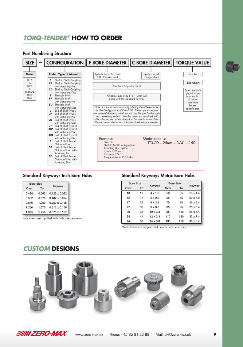
TORQ-TENDER® HOW TO ORDER
Inch bores are supplied with inch size setscrews.
Metric bores are supplied with metric size setscrews.
CUSTOM DESIGNS
Standard Keyways Inch Bore Hubs Standard Keyways Metric Bore Hubs
Bore SizeKeyway
Over To
0.438 0.562 0.125 x 0.062
0.562 0.875 0.187 x 0.094
0.875 1.250 0.250 x 0.125
1.250 1.375 0.312 x 0.156
1.375 1.750 0.375 x 0.187
Bore SizeKeyway
Bore SizeKeyway
Over To Over To
10 12 4 x 1.8 58 65 18 x 4.4
12 17 5 x 2.3 65 75 20 x 4.9
17 22 6 x 2.8 75 85 22 x 5.4
22 30 8 x 3.3 85 95 25 x 5.4
30 38 10 x 3.3 95 110 28 x 6.4
38 44 12 x 3.3 110 130 32 x 7.4
44 50 14 x 3.8 130 150 36 x 8.4
Part Numbering Structure
–SIZE
TT1XTT2TT2XTT3
TT3TANTT3XTT4X
CONFIGURATION TORQUE VALUE
C Shaft to Shaft Coupling CP Shaft to Shaft Coupling
with Actuating Pin CD Shaft to Shaft Coupling
with Actuating Disc B Through Shaft BP Through Shaft
with Actuating Pin BD Through Shaft
with Actuating Disc J End of Shaft Type J JP End of Shaft Type J
with Actuating Pin JD End of Shaft Type J
with Actuating Disc JF End of Shaft Type JF JFP End of Shaft Type JF
with Actuating Pin JFD End of Shaft Type JF
with Actuating Disc S End of Shaft Mount
Outboard load SP End of Shaft Mount
Outboard load with Actuating Pin
SD End of Shaft Mount Outboard load with Actuating Disc
in - lbs.
F BORE DIAMETER
Specify for C, CP, and CD otherwise omit
C BORE DIAMETER
Specify for all configurations
See Bore Capacity Chart
Select the inch pound value from the list of values available for the
specific size
See Chart.
Code Code Type of Mount
All bores over 0.438” or 10mm will come with the standard keyway
Note: It is important to correctly identify the different bores for the Configurations CP and CD. These options require
an external device to interface with the Torque Tender such as a proximity switch. How the bores are specified will
affect the location of the Actuation Pin and Actuation Disc. Please contact the factory if further clarification is needed.
Example: Size TT3 Shaft to Shaft Configuration Actuating Disc option F bore is 25mm C bore is 3/4” Torque value is 150 in-lbs.
Model code is: TT3-CD – 25mm – 3/4” – 150
9
TORQ-TENDER® HOW TO ORDER
Inch bores are supplied with inch size setscrews.
Metric bores are supplied with metric size setscrews.
CUSTOM DESIGNS
Standard Keyways Inch Bore Hubs Standard Keyways Metric Bore Hubs
Bore SizeKeyway
Over To
0.438 0.562 0.125 x 0.062
0.562 0.875 0.187 x 0.094
0.875 1.250 0.250 x 0.125
1.250 1.375 0.312 x 0.156
1.375 1.750 0.375 x 0.187
Bore SizeKeyway
Bore SizeKeyway
Over To Over To
10 12 4 x 1.8 58 65 18 x 4.4
12 17 5 x 2.3 65 75 20 x 4.9
17 22 6 x 2.8 75 85 22 x 5.4
22 30 8 x 3.3 85 95 25 x 5.4
30 38 10 x 3.3 95 110 28 x 6.4
38 44 12 x 3.3 110 130 32 x 7.4
44 50 14 x 3.8 130 150 36 x 8.4
Part Numbering Structure
–SIZE
TT1XTT2TT2XTT3
TT3TANTT3XTT4X
CONFIGURATION TORQUE VALUE
C Shaft to Shaft Coupling CP Shaft to Shaft Coupling
with Actuating Pin CD Shaft to Shaft Coupling
with Actuating Disc B Through Shaft BP Through Shaft
with Actuating Pin BD Through Shaft
with Actuating Disc J End of Shaft Type J JP End of Shaft Type J
with Actuating Pin JD End of Shaft Type J
with Actuating Disc JF End of Shaft Type JF JFP End of Shaft Type JF
with Actuating Pin JFD End of Shaft Type JF
with Actuating Disc S End of Shaft Mount
Outboard load SP End of Shaft Mount
Outboard load with Actuating Pin
SD End of Shaft Mount Outboard load with Actuating Disc
in - lbs.
F BORE DIAMETER
Specify for C, CP, and CD otherwise omit
C BORE DIAMETER
Specify for all configurations
See Bore Capacity Chart
Select the inch pound value from the list of values available for the
specific size
See Chart.
Code Code Type of Mount
All bores over 0.438” or 10mm will come with the standard keyway
Note: It is important to correctly identify the different bores for the Configurations CP and CD. These options require
an external device to interface with the Torque Tender such as a proximity switch. How the bores are specified will
affect the location of the Actuation Pin and Actuation Disc. Please contact the factory if further clarification is needed.
Example: Size TT3 Shaft to Shaft Configuration Actuating Disc option F bore is 25mm C bore is 3/4” Torque value is 150 in-lbs.
Model code is: TT3-CD – 25mm – 3/4” – 150
www.zero-max.dk Phone: +45 86 81 22 88 Mail: [email protected] 9
10 www.zero-max.com Phone 800.533.1731 763.546.4300 Fax 763.546.8260
TORQ-TENDER® H-TLC TORQUE LIMITERS
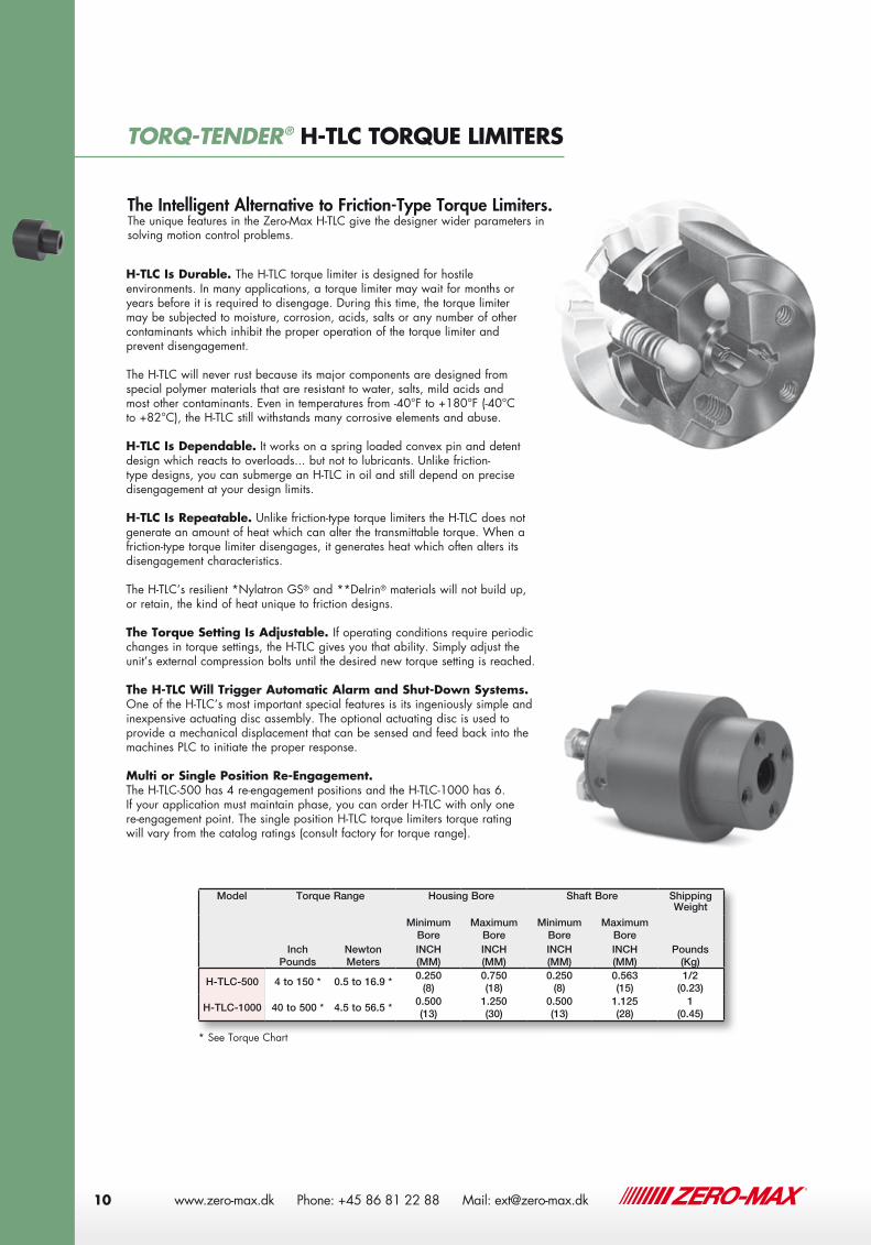
H-TLC Is Durable. The H-TLC torque limiter is designed for hostile environments. In many applications, a torque limiter may wait for months or years before it is required to disengage. During this time, the torque limiter may be subjected to moisture, corrosion, acids, salts or any number of other contaminants which inhibit the proper operation of the torque limiter and prevent disengagement.
The H-TLC will never rust because its major components are designed from special polymer materials that are resistant to water, salts, mild acids and most other contaminants. Even in temperatures from -40°F to +180°F (-40°C to +82°C), the H-TLC still withstands many corrosive elements and abuse.
H-TLC Is Dependable. It works on a spring loaded convex pin and detent design which reacts to overloads... but not to lubricants. Unlike friction-type designs, you can submerge an H-TLC in oil and still depend on precise disengagement at your design limits.
H-TLC Is Repeatable. Unlike friction-type torque limiters the H-TLC does not generate an amount of heat which can alter the transmittable torque. When a friction-type torque limiter disengages, it generates heat which often alters its disengagement characteristics.
The H-TLC’s resilient *Nylatron GS® and **Delrin® materials will not build up, or retain, the kind of heat unique to friction designs.
The Torque Setting Is Adjustable. If operating conditions require periodic changes in torque settings, the H-TLC gives you that ability. Simply adjust the unit’s external compression bolts until the desired new torque setting is reached.
The H-TLC Will Trigger Automatic Alarm and Shut-Down Systems. One of the H-TLC’s most important special features is its ingeniously simple and inexpensive actuating disc assembly. The optional actuating disc is used to provide a mechanical displacement that can be sensed and feed back into the machines PLC to initiate the proper response.
Multi or Single Position Re-Engagement. The H-TLC-500 has 4 re-engagement positions and the H-TLC-1000 has 6. If your application must maintain phase, you can order H-TLC with only one re-engagement point. The single position H-TLC torque limiters torque rating will vary from the catalog ratings (consult factory for torque range).
The Intelligent Alternative to Friction-Type Torque Limiters.The unique features in the Zero-Max H-TLC give the designer wider parameters in solving motion control problems.
Model Torque Range Housing Bore Shaft Bore Shipping Weight
Inch Pounds
Newton Meters
Minimum Bore
Maximum Bore
Minimum Bore
Maximum Bore
Pounds (Kg)
INCH (MM)
INCH (MM)
INCH (MM)
INCH (MM)
H-TLC-500 4 to 150 * 0.5 to 16.9 *0.250
(8)0.750 (18)
0.250 (8)
0.563 (15)
1/2 (0.23)
H-TLC-1000 40 to 500 * 4.5 to 56.5 *0.500 (13)
1.250 (30)
0.500 (13)
1.125 (28)
1 (0.45)
* See Torque Chart
Note: *Nylatron GS® is a registered trademark of Polymer Corp. **Delrin® is a registered trademark of EI Dupont Company
TORQ-TENDER® H-TLC TORQUE LIMITERS
www.zero-max.dk Phone: +45 86 81 22 88 Mail: [email protected]

TORQ-TENDER® H-TLC TORQUE LIMITERS
11
H-TLC Dimensions
Models 500 1000
AINCH (MM)
2.00 (50.8)
3.20 (81.3)
BINCH (MM)
1.49 (37.8)
2.37 (60.2)
DINCH (MM)
1.625 (41.3)
2.230 (56.6)
EINCH (MM)
0.855 (21.7)
1.210 (30.7)
GINCH (MM)
1.49 (37.8)
2.22 (56.4)
HINCH (MM)
0.250 (6.3)
0.315 (8)
H1INCH (MM)
1.250 (31.7)
1.625 (41.3)
IINCH (MM)
0.563 (14.3)
0.520 (13.2)
JINCH (MM)
1.187 (30.1)
1.81 (58.4)
KINCH (MM)
2.50 (63.5)
3.45 (87.6)
LINCH (MM)
0.750 (19)
1.12 (15.9)
MINCH (MM)
0.375 (9.5)
0.400 (10.2)
QINCH (MM)
1.125 (28.6)
1.687 (42.8)
R INCH1/4-20
x 1/2 DP5/16-18 x 3/4 DP
XINCH (MM)
2.50 (63.5)
4.040 (102.6)
ZINCH (MM)
2.275 (57.8)
3.270 (83.1)
Z1INCH (MM)
2.125 (54)
3.110 (79)
X B
K
G A Q
Z1ENGAGED
ZDISENGAGED
SLEEVE BEARING
C BORE
B A
H H1
J
K
L I
Q
R
B A
F BOREC BORE
K
I J L
G
H1 M H
E D
O KEYWAYN KEYWAY
X B
K
G A Q
Z1ENGAGED
ZDISENGAGED
SLEEVE BEARING
C BORE
B A
H H1
J
K
L I
Q
R
X B
K
G A Q
Z1ENGAGED
ZDISENGAGED
SLEEVE BEARING
C BORE
B A
H H1
J
K
L I
Q
R
B A
F BOREC BORE
K
I J L
G
H1 M H
E D
O KEYWAYN KEYWAY
Sprocket Not Included
H-TLC Type C
H-TLC Type B
H-TLC Type CD and BD (with Actuating Disc)
B A
F BOREC BORE
K
I J L
G
H1 M H
E D
O KEYWAYN KEYWAY
Part Numbering Structure
–SIZE
H-TLC-500H-TLC-1000
CONFIGURATION TORQUE VALUE
C Shaft to Shaft Mount CD Shaft to Shaft Mount with Actuating Disc B Through Shaft Mount BD Through Shaft Mount with Actuating Disc
Code
F BORE DIAMETER
Specify for C and CD otherwise omit
C BORE DIAMETER
Specify for all configurations
See Bore Capacity Chart
Code Code Type of Mount
All bores over 0.438” or 10mm will come with the standard keyway
Note: It is important to correctly identify the different bores for the Configuration CD. These options require
an external device to interface with the H-TLC such as a proximity switch. How the bores are specified will affect
the location of the Actuation Disc. Please contact the factory if further clarification is needed.
Example: Size H-TLC Shaft to Shaft Configuration Actuating Disc option F bore is 25mm C bore is 3/4” Torque value is 300 to 500 in-lbs.
Model code is:H-TLC-1000-CD 25mm 3/4” Gold
Series Code Torque Range
500 Series
Blue 4 to 60 In-lbs. 0.5 to 6.8 Nm
Red 40 to 125 In-lbs. 4.5 to 14.1 Nm
Gold 100 to 150 In-lbs. 11.3 to 16.9 Nm
1000 Series
Blue 40 to 150 In-lbs. 4.5 to 16.9 Nm
Red140 to 350 In-lbs. 15.8 to 39.5 Nm
Gold 300 to 500 In-lbs. 33.9 to 56.5 Nm
www.zero-max.dk Phone: +45 86 81 22 88 Mail: [email protected] 11

Haarup Tvaervej 1, DK-8600 Silkeborg, DenmarkPhone: +45 86 81 22 88 Fax: +45 86 81 53 88
www.zero-max.dk Email: [email protected]