overview of led lighting
TRANSCRIPT

Created by Bernie Weir
High Brightness LED Driver Solutions for General Lighting
2
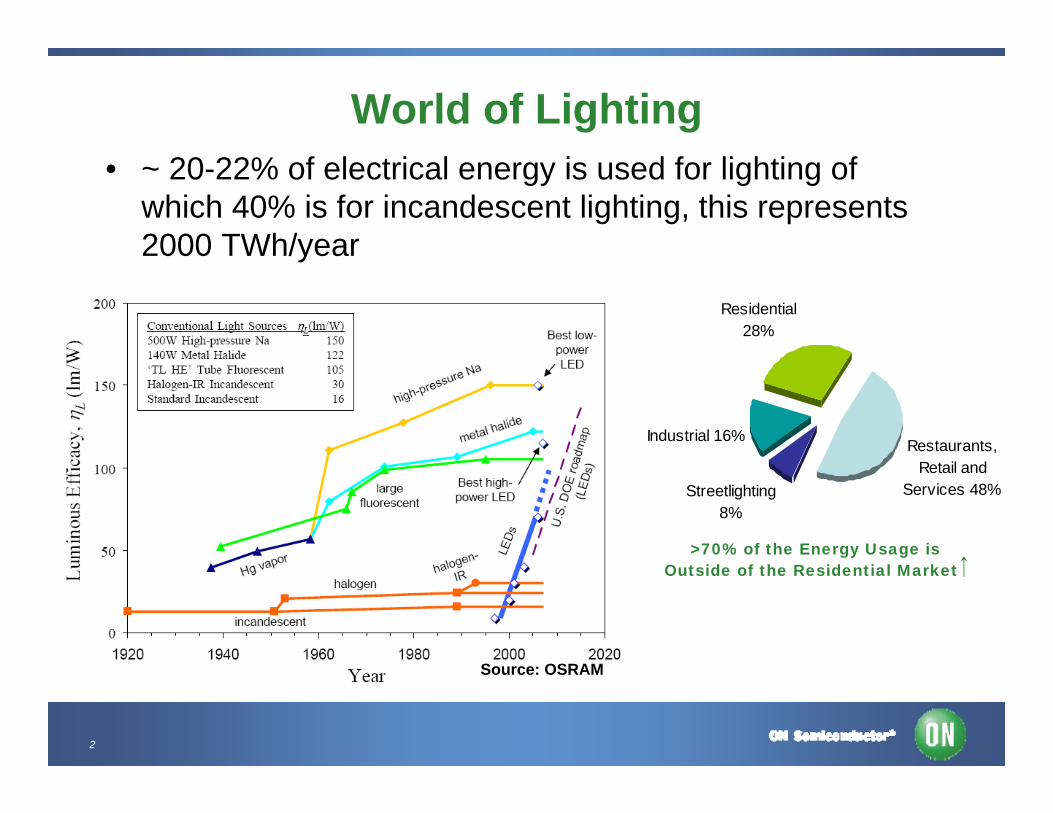
Source: OSRAM
World of Lighting• ~ 20-22% of electrical energy is used for lighting of
which 40% is for incandescent lighting, this represents 2000 TWh/year
Restaurants, Retail and
Services 48%
Industrial 16%
Residential 28%
Streetlighting 8%
>70% of the Energy Usage is Outside of the Residential Market
3
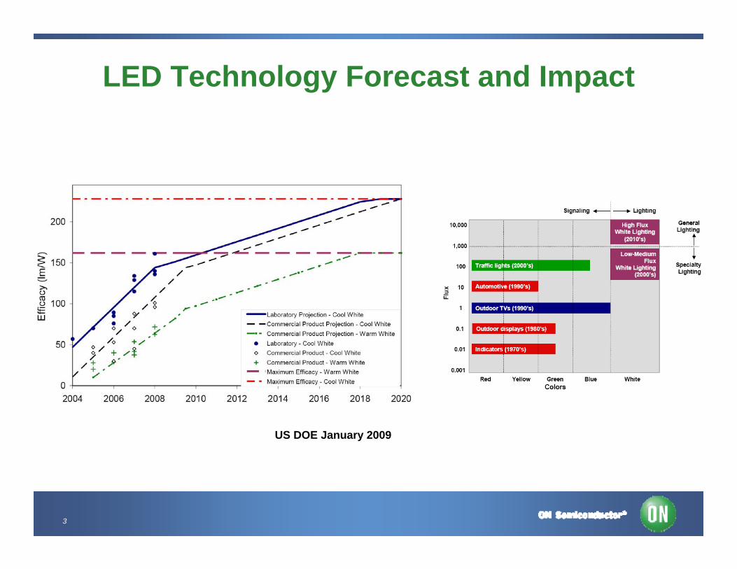
LED Technology Forecast and Impact
US DOE January 2009
4
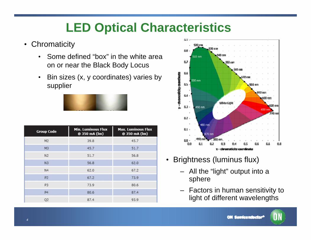
LED Optical Characteristics• Chromaticity
• Some defined “box” in the white area on or near the Black Body Locus
• Bin sizes (x, y coordinates) varies by supplier
• Brightness (luminus flux)– All the “light” output into a
sphere– Factors in human sensitivity to
light of different wavelengths
5
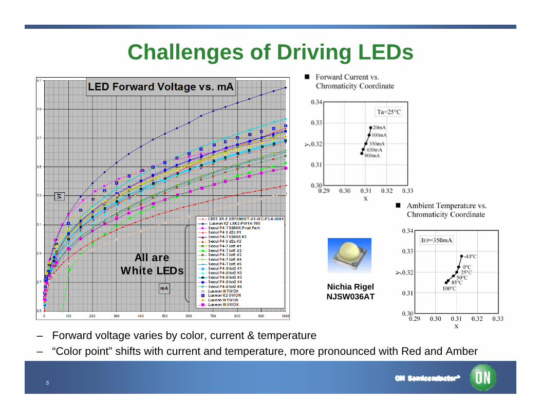
Challenges of Driving LEDs
– Forward voltage varies by color, current & temperature– “Color point” shifts with current and temperature, more pronounced with Red and Amber
Nichia RigelNJSW036AT
All areWhite LEDs
6
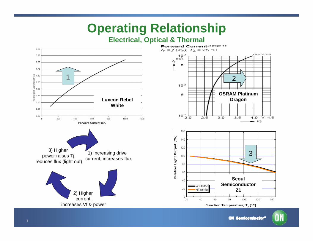
Operating RelationshipElectrical, Optical & Thermal
Luxeon Rebel White
OSRAM PlatinumDragon
Seoul Semiconductor
Z1
1) Increasing drive current, increases flux
2) Higher current,
increases Vf & power
3) Higher power raises Tj,
reduces flux (light out)
1 2
3
7
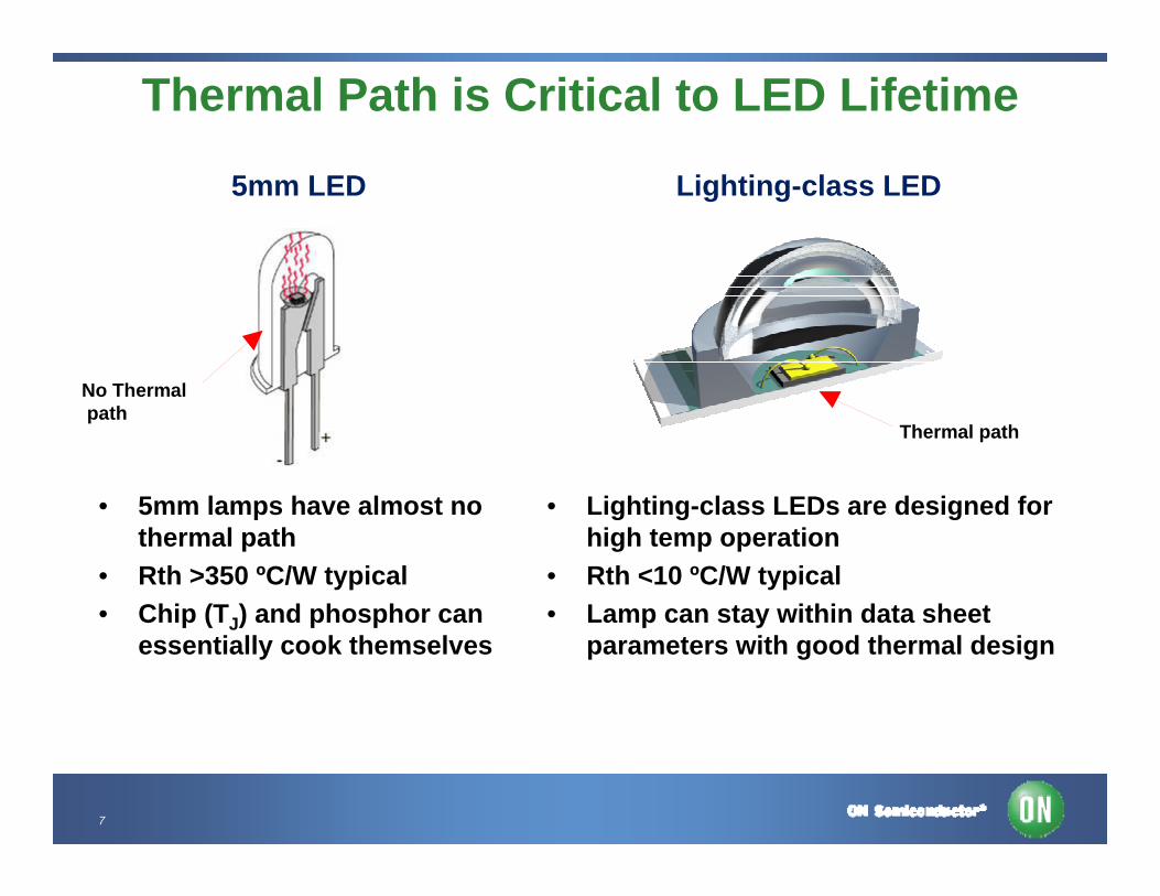
Thermal Path is Critical to LED Lifetime
• 5mm lamps have almost no thermal path
• Rth >350 ºC/W typical• Chip (TJ) and phosphor can
essentially cook themselves
• Lighting-class LEDs are designed for high temp operation
• Rth <10 ºC/W typical• Lamp can stay within data sheet
parameters with good thermal design
Thermal path
Lighting-class LED5mm LED
No Thermalpath
8
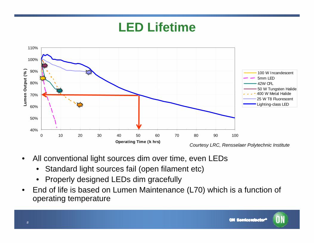
LED Lifetime
40%
50%
60%
70%
80%
90%
100%
110%
0 10 20 30 40 50 60 70 80 90 100
Operating Time (k hrs)
Lum
en O
utp
ut
(%)
100 W Incandescent5mm LED42W CFL50 W Tungsten Halide400 W Metal Halide25 W T8 FluorescentLighting-class LED
• All conventional light sources dim over time, even LEDs• Standard light sources fail (open filament etc)• Properly designed LEDs dim gracefully
• End of life is based on Lumen Maintenance (L70) which is a function of operating temperature
Courtesy LRC, Rensselaer Polytechnic Institute
9
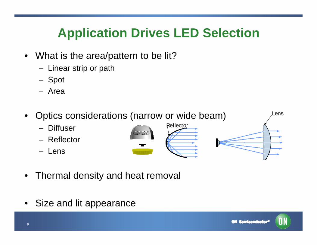
Application Drives LED Selection• What is the area/pattern to be lit?
– Linear strip or path– Spot– Area
• Optics considerations (narrow or wide beam)– Diffuser– Reflector– Lens
• Thermal density and heat removal
• Size and lit appearance
Reflector
Lens
10
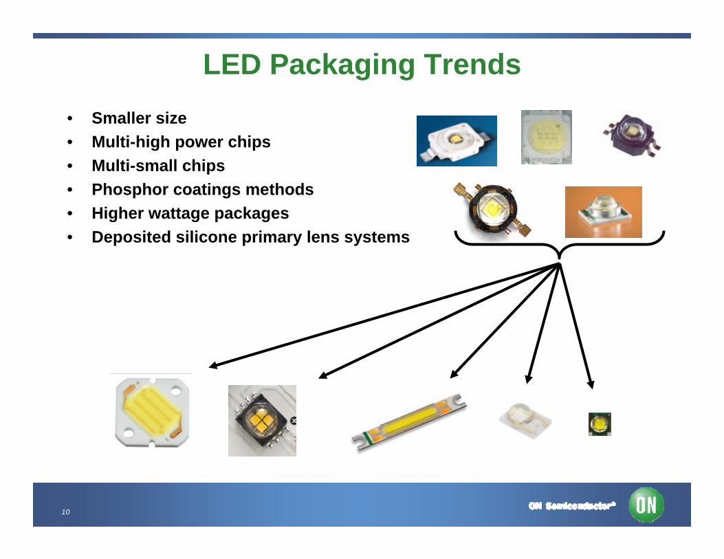
LED Packaging Trends• Smaller size• Multi-high power chips• Multi-small chips• Phosphor coatings methods • Higher wattage packages• Deposited silicone primary lens systems
11
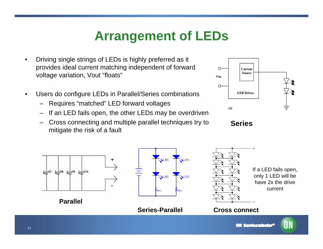
Arrangement of LEDs• Driving single strings of LEDs is highly preferred as it
provides ideal current matching independent of forward voltage variation, Vout “floats”
• Users do configure LEDs in Parallel/Series combinations – Requires “matched” LED forward voltages– If an LED fails open, the other LEDs may be overdriven– Cross connecting and multiple parallel techniques try to
mitigate the risk of a fault
Parallel
If a LED fails open, only 1 LED will be have 2x the drive
current
Series-Parallel Cross connect
Series
12
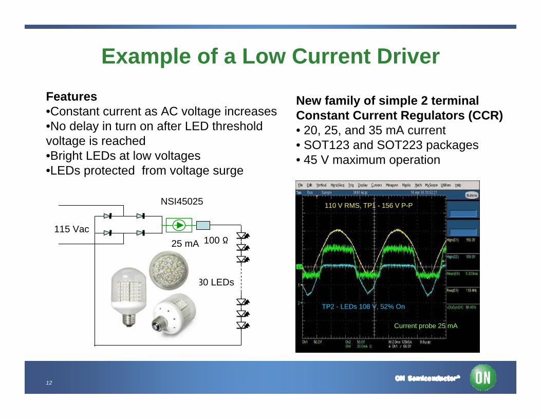
Example of a Low Current Driver
115 Vac25 mA 100 Ω
30 LEDs
110 V RMS, TP1 - 156 V P-P
TP2 - LEDs 108 V, 52% On
Current probe 25 mA
Features•Constant current as AC voltage increases•No delay in turn on after LED threshold voltage is reached•Bright LEDs at low voltages•LEDs protected from voltage surge
New family of simple 2 terminal Constant Current Regulators (CCR)• 20, 25, and 35 mA current• SOT123 and SOT223 packages• 45 V maximum operation
NSI45025
13
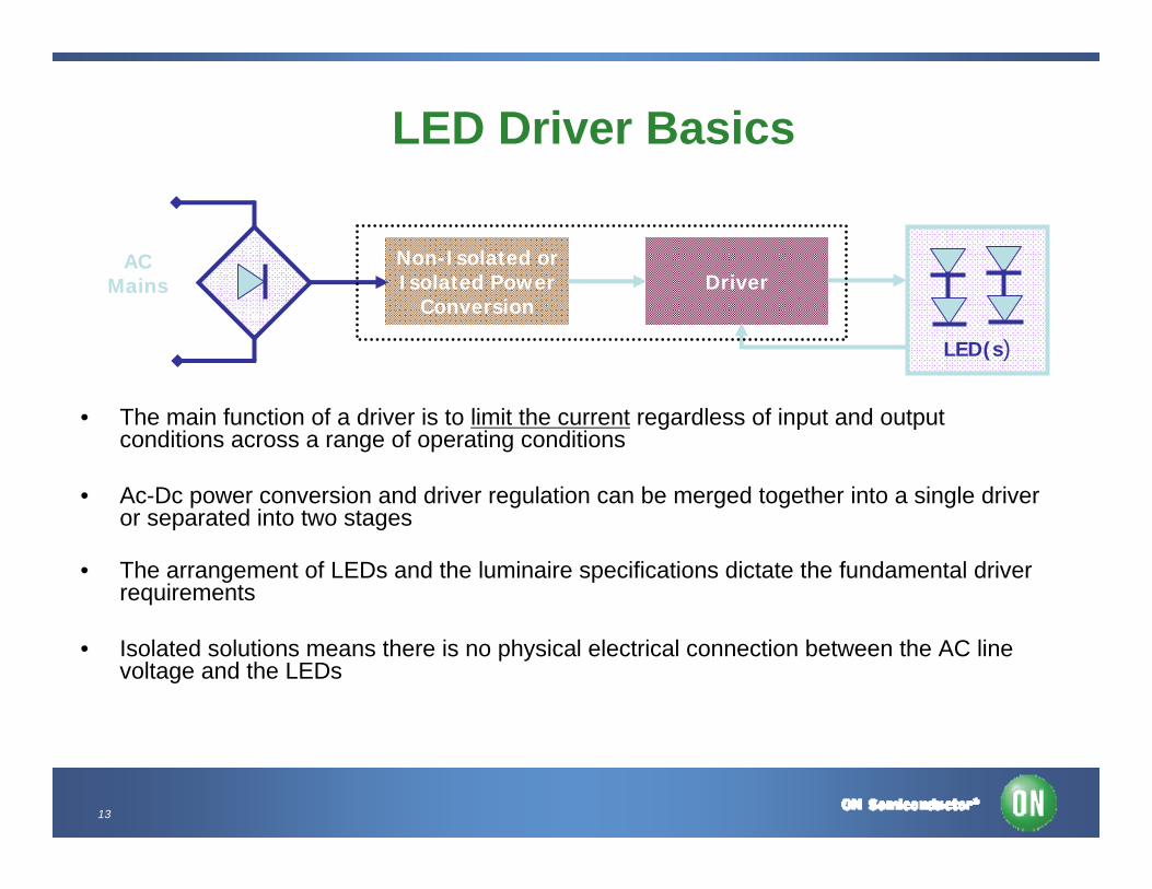
LED Driver Basics
• The main function of a driver is to limit the current regardless of input and output conditions across a range of operating conditions
• Ac-Dc power conversion and driver regulation can be merged together into a single driver or separated into two stages
• The arrangement of LEDs and the luminaire specifications dictate the fundamental driver requirements
• Isolated solutions means there is no physical electrical connection between the AC line voltage and the LEDs
Non-Isolated orIsolated Power
ConversionDriver
LED(s)
ACMains
14
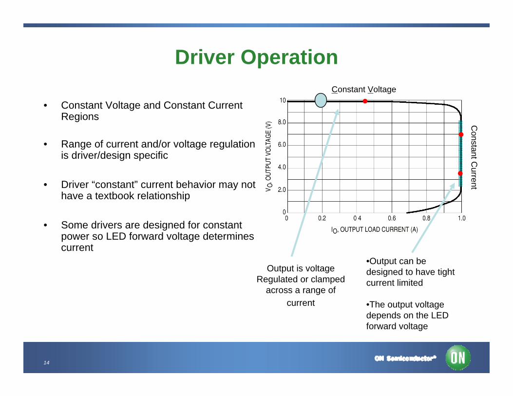
Driver Operation
• Constant Voltage and Constant Current Regions
• Range of current and/or voltage regulation is driver/design specific
• Driver “constant” current behavior may not have a textbook relationship
• Some drivers are designed for constant power so LED forward voltage determines current
•Output can be designed to have tight current limited
•The output voltage depends on the LED forward voltage
Output is voltageRegulated or clamped
across a range of current
Constant Voltage
Constant C
urrent
15
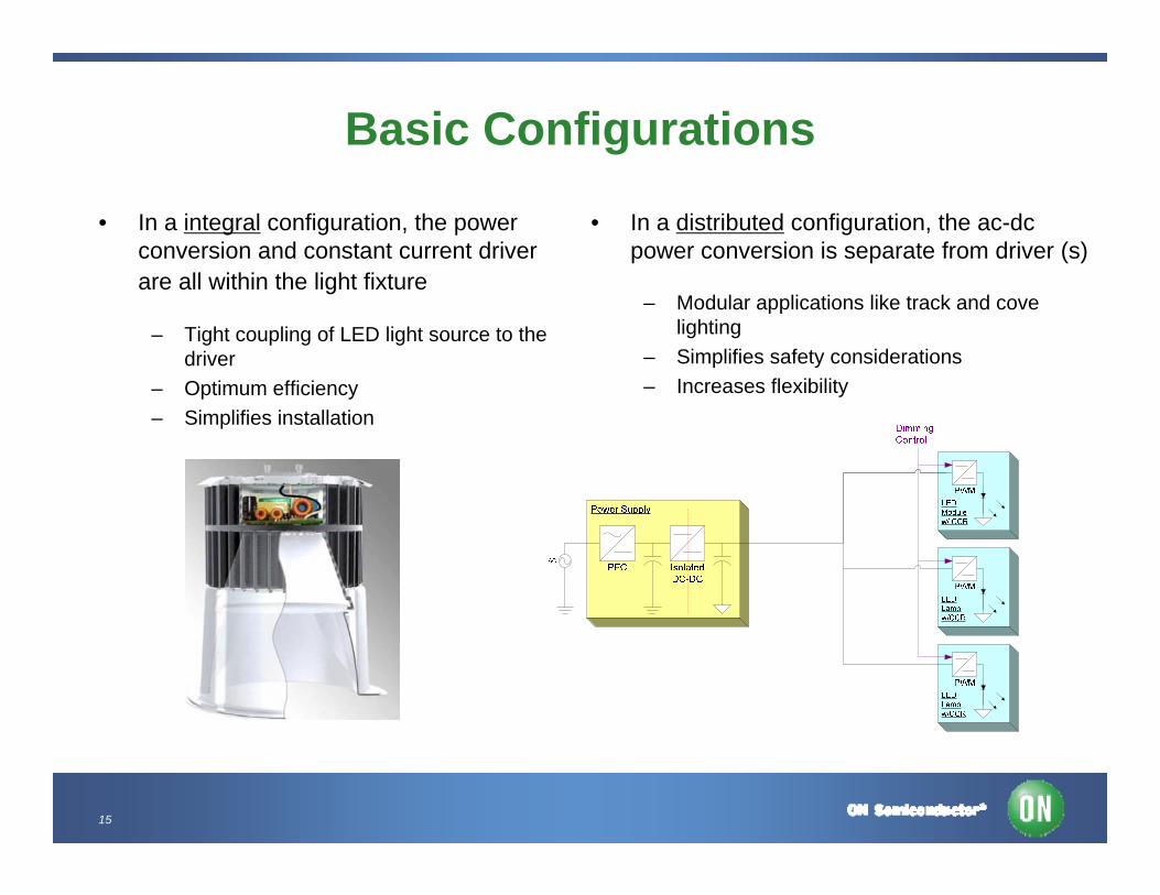
Basic Configurations
• In a integral configuration, the power conversion and constant current driver are all within the light fixture
– Tight coupling of LED light source to the driver
– Optimum efficiency– Simplifies installation
• In a distributed configuration, the ac-dc power conversion is separate from driver (s)
– Modular applications like track and cove lighting
– Simplifies safety considerations– Increases flexibility

16
Offline LED Applications by Power LevelBased on Today’s LED Performance
• Low Power– 1-12 W
• Medium Power– 8-40 W
• High Power– >40 W
• Under-cabinet lighting• Desk Lamps• Accent• Appliances• A lamp Bulb Replacement
• Down Lighting• Spot Light (PAR38) Equivalent• Decorative Light Fixtures• Bollards• Ceiling Fans• Freezer and Refrigerator Lights• High Efficiency LED Supplies (ballasts) (24 V/ 48 V)
• Area Lighting– Street Lights– Fluorescent Lights– HID Replacement
• High Efficiency LED Supplies (ballasts) (24 V/ 48 V)

17
Factors to Consider• Output Power
– Range of LED forward voltage– Current – target, maximum– LED arrangement
• Power Source– 115 Vac, Universal (US/EU),
Industrial – 208/277 Vac or other– Low Voltage Lighting (landscape,
track etc)– Solar / Battery
• Functional Requirements– Dimming – PWM, 0 - 10 V, Triac,
Wireless, DALI, Proprietary, Other– Analog, Digital, or multi-level
dimming– Lighting Control – occupancy,
motion, timer
• Additional Requirements– Efficiency– Power Factor– Size – Cost– Fault handling (short circuit, open
circuit, overload, over temperature– Standards – Safety (UL,CSA,VDE)– Energy Star– Reliability
• Other Considerations– Mechanical connections– Installation– Repair / Replacement– Lifecycle– Logistics
18
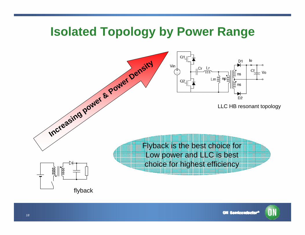
Isolated Topology by Power Range
Increasing power & Power D
ensity
flyback
LLC HB resonant topology
Flyback is the best choice forLow power and LLC is bestchoice for highest efficiency
19
Offline LED Specific Standards• ENERGYSTAR™ SSL Specification (Version 1.1 -2/2009)
– Luminaire based limits, product specific requirements including power factor– No “off state” power requirement rules out standard wall plug adapters, exception are
devices with smart controls, standby < 0.5 W in those cases Electromagnetic & RFI per FCC 47 CFR Part 15/18
• IEC 61347-2-13 (5/2006) - Requirements for DC or AC supplied electronic control gear for LED Modules include:
– Maximum SELV operating output voltage <= 25V rms (35.3 Vdc)– “Proper” /Safe operation under various fault conditions:
• No LEDs testing and 2x the rated LEDs or modules• Output short circuited
– No smoke emission or flammability under malfunction
• ANSI C82.xxx LED Driver specification in development
• Safety – UL, CSA etc - UL1310 (Class 2) / UL 60950 / UL1012 – See appendix for more information
20
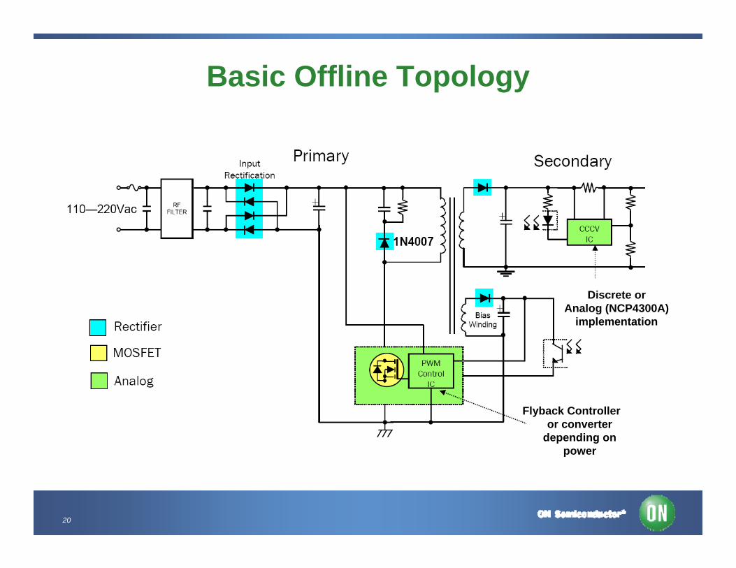
Basic Offline Topology
Flyback Controlleror converter
depending on power
Discrete orAnalog (NCP4300A)
implementation
21
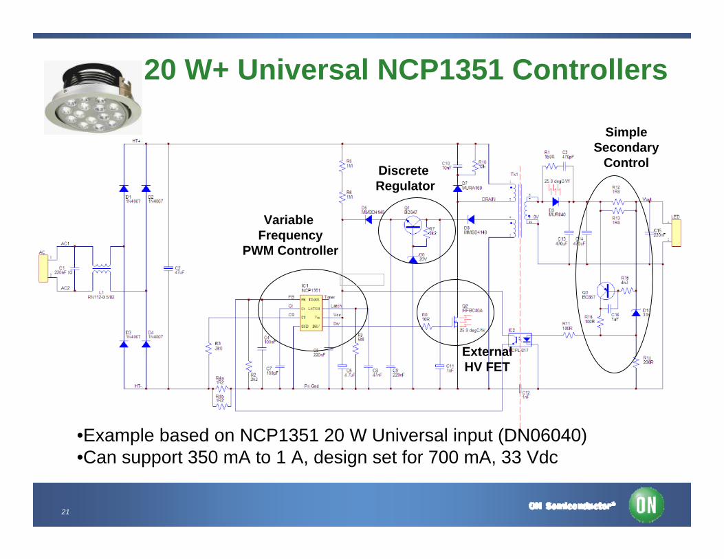
20 W+ Universal NCP1351 Controllers
•Example based on NCP1351 20 W Universal input (DN06040)•Can support 350 mA to 1 A, design set for 700 mA, 33 Vdc
SimpleSecondary
Control
Variable Frequency
PWM Controller
ExternalHV FET
Discrete Regulator

22
NCP1351 LED Demo Board PerformanceEfficiency across Vf and Line (Iout = 700 mA nom)
0%
10%
20%
30%
40%
50%
60%
70%
80%
90%
0 5 10 15 20 25 30
LED Voltage (Vdc)
Effic
ienc
y (%
)
115 Vac230 Vac125 x 37 x 35 mm
23
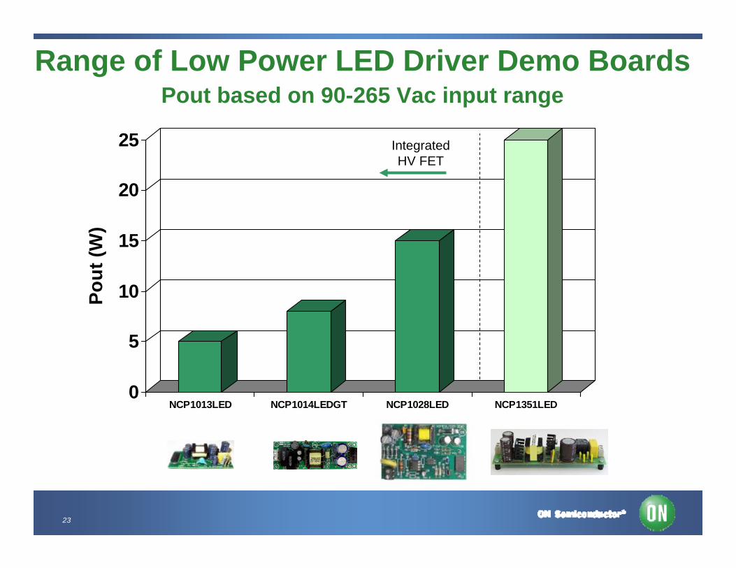
Range of Low Power LED Driver Demo BoardsPout based on 90-265 Vac input range
0
5
10
15
20
25
Pout
(W)
NCP1013LED NCP1014LEDGT NCP1028LED NCP1351LED
IntegratedHV FET
24
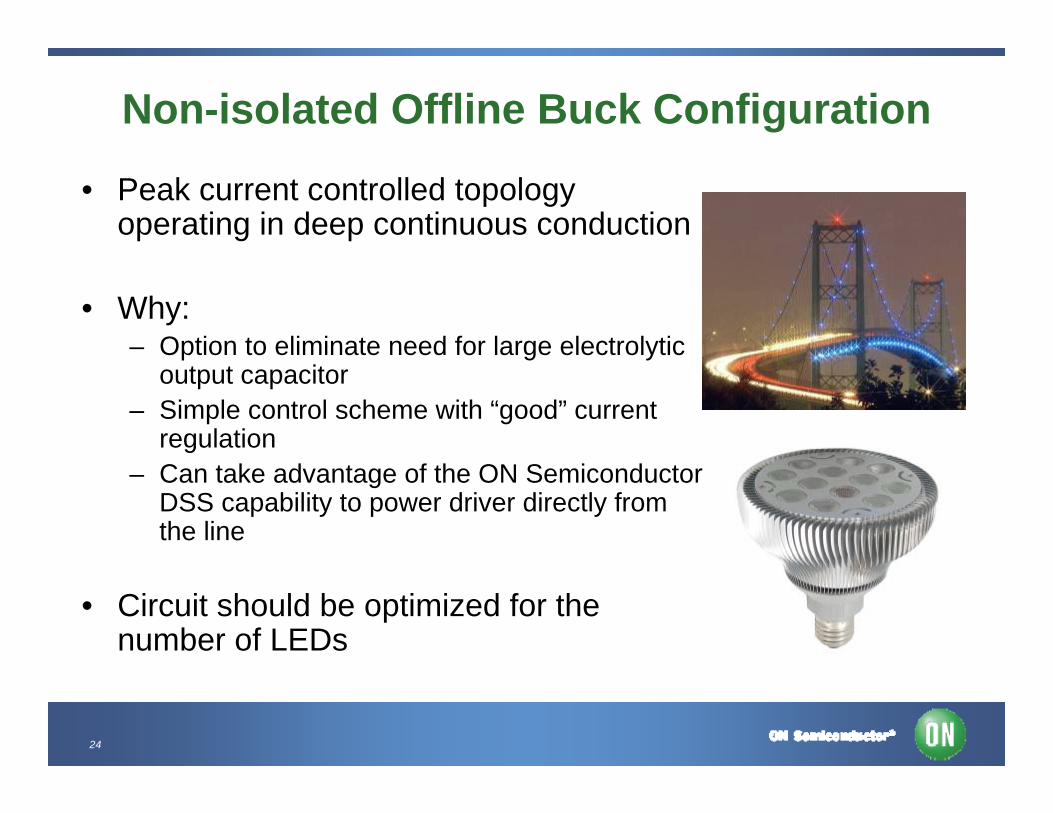
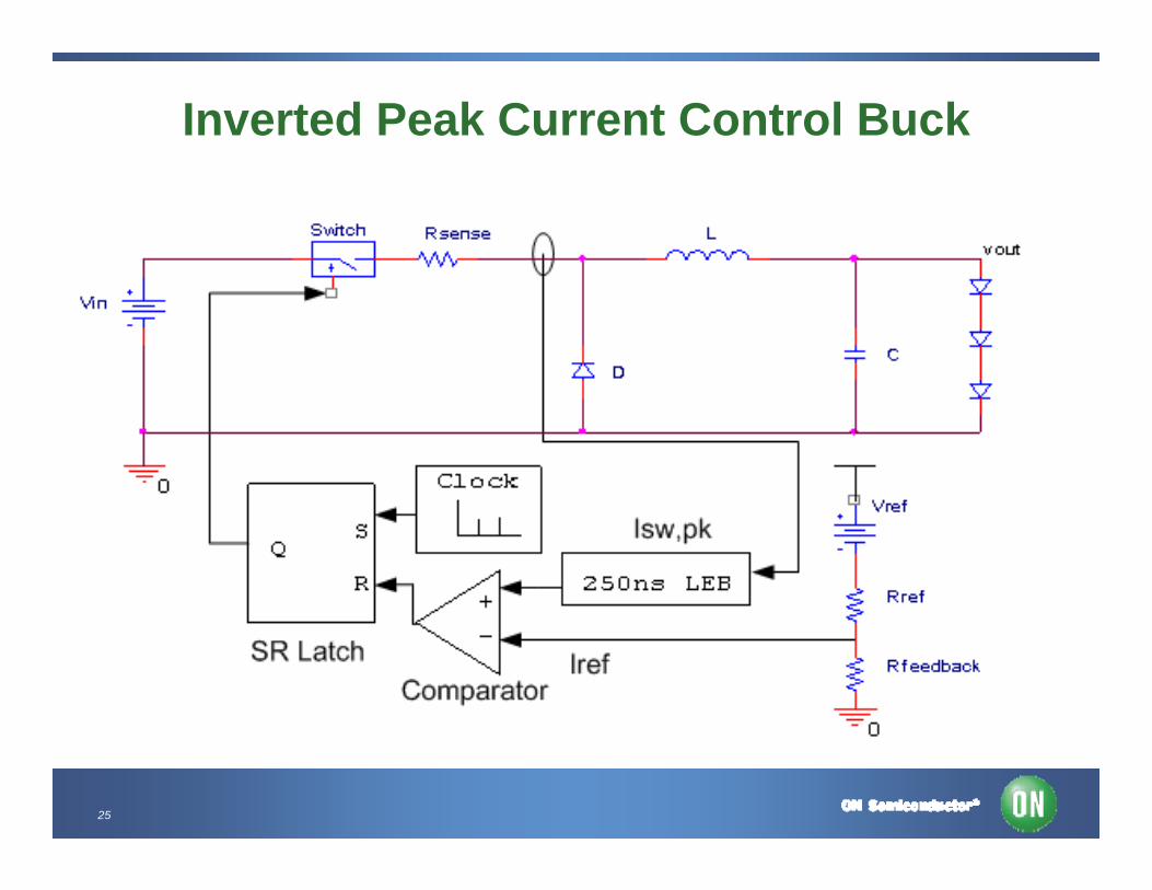
Non-isolated Offline Buck Configuration
• Peak current controlled topology operating in deep continuous conduction
• Why:– Option to eliminate need for large electrolytic
output capacitor– Simple control scheme with “good” current
regulation– Can take advantage of the ON Semiconductor
DSS capability to power driver directly from the line
• Circuit should be optimized for the number of LEDs
25
Inverted Peak Current Control Buck
26
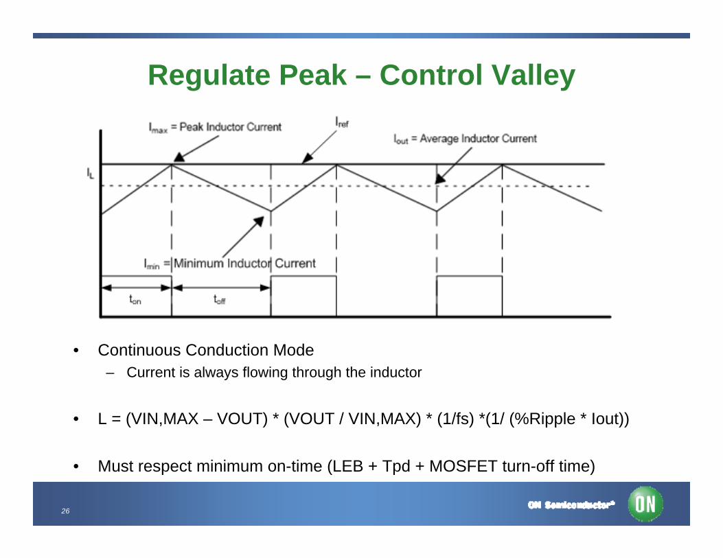
Regulate Peak – Control Valley
• Continuous Conduction Mode – Current is always flowing through the inductor
• L = (VIN,MAX – VOUT) * (VOUT / VIN,MAX) * (1/fs) *(1/ (%Ripple * Iout))
• Must respect minimum on-time (LEB + Tpd + MOSFET turn-off time)
27
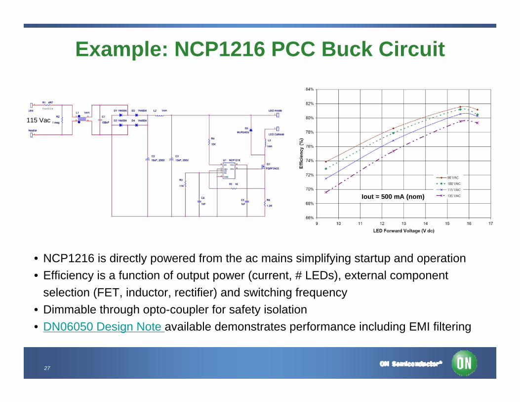
Example: NCP1216 PCC Buck Circuit
• NCP1216 is directly powered from the ac mains simplifying startup and operation• Efficiency is a function of output power (current, # LEDs), external component
selection (FET, inductor, rectifier) and switching frequency• Dimmable through opto-coupler for safety isolation• DN06050 Design Note available demonstrates performance including EMI filtering
Iout = 500 mA (nom)
115 Vac
28
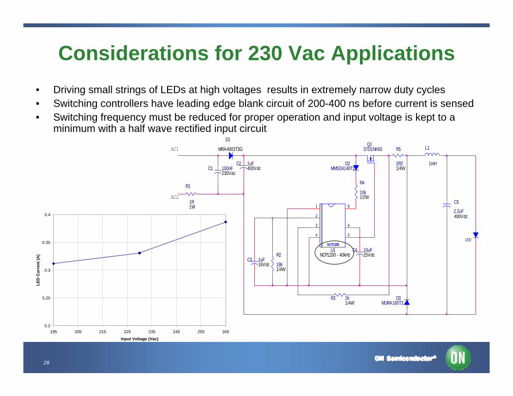
Considerations for 230 Vac Applications• Driving small strings of LEDs at high voltages results in extremely narrow duty cycles• Switching controllers have leading edge blank circuit of 200-400 ns before current is sensed• Switching frequency must be reduced for proper operation and input voltage is kept to a
minimum with a half wave rectified input circuit
100nFC1C2 1uF
C5
2.2uF
C3 1uF
C4 10uF
D1
D3MURA160T3
D2MMSD4148T1
R1
1R
R2
18k
LED
R4
10k
R3 2k
Q1STD1NK60 R5
2R2
L1
1mH
AC2
AC1
NCP1200U1
1
2
3
4 5
6
8
1/4W230Vac
400Vdc
16Vdc
MRA4003T3G
25Vdc
1/2W
1/4W
1W
1/4W
400Vdc
NCP1200 - 40kHz
0.2
0.25
0.3
0.35
0.4
195 205 215 225 235 245 255 265
Input Voltage (Vac)
LED
Cur
rent
(A)
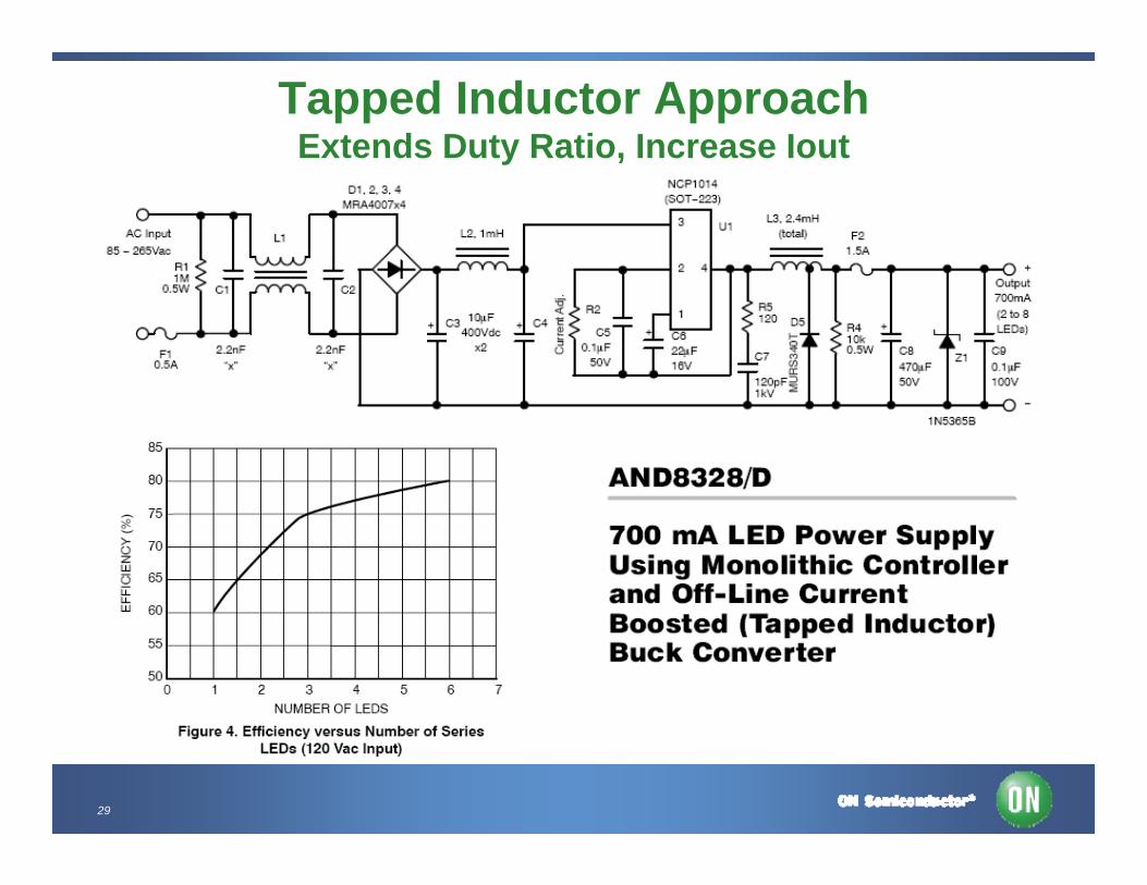
29
Tapped Inductor ApproachExtends Duty Ratio, Increase Iout
30
Power Factor Requirements for Offline LED Drivers
• IEC (EU) requirements dictate THD performance for Lighting (over 25 W), other international standards apply depending on the region
• US DOE ENERGY STAR™ includes mandatory PFC for Solid State Lighting regardless of the power level. This is a voluntary standard and applies to a specific set of products such as down lights, under cabinet lights and desk lamps for example
– >0.7 for residential applications– >0.9 for commercial applications
• While not absolutely mandated in the for lighting in all countries, it may be required based on the application:– Utilities drive major commercial uses to have high PF at the facility level– Moreover when utilities owns/service the streetlight it is in their interest to have
good power factor, typically > 0.95+
31
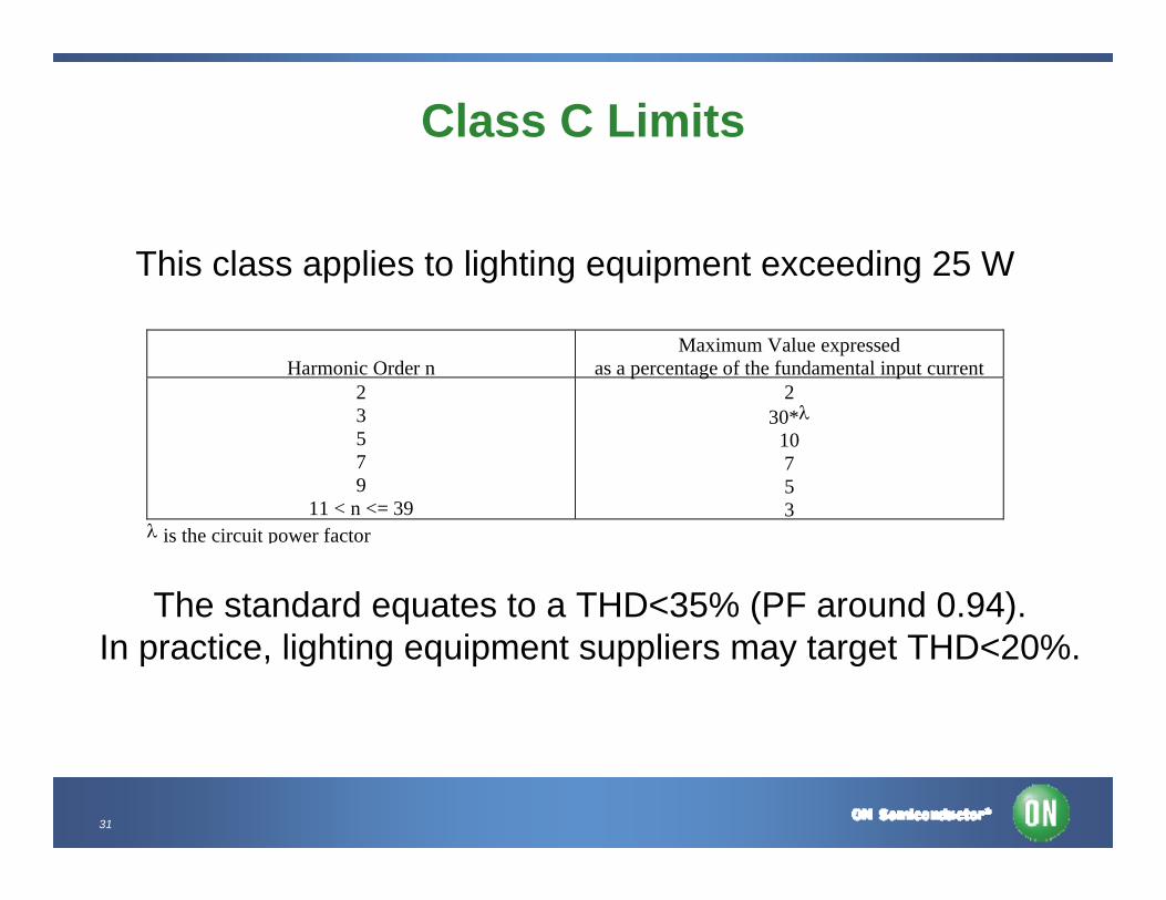
Class C Limits
Harmonic Order nMaximum Value expressed
as a percentage of the fundamental input current23579
11 < n <= 39
230*λ
10753
λ is the circuit power factor
This class applies to lighting equipment exceeding 25 W
The standard equates to a THD<35% (PF around 0.94).In practice, lighting equipment suppliers may target THD<20%.
32
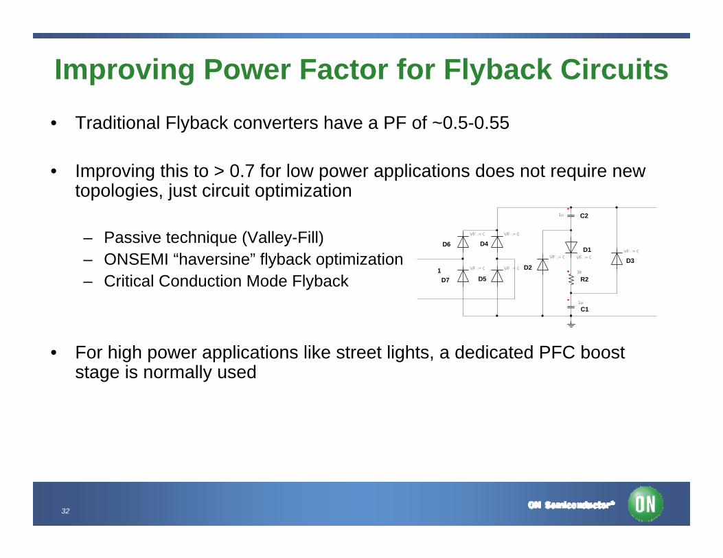
Improving Power Factor for Flyback Circuits • Traditional Flyback converters have a PF of ~0.5-0.55
• Improving this to > 0.7 for low power applications does not require new topologies, just circuit optimization
– Passive technique (Valley-Fill)– ONSEMI “haversine” flyback optimization– Critical Conduction Mode Flyback
• For high power applications like street lights, a dedicated PFC boost stage is normally used
D7 D5
D6 D4
D2
D1D3
R2
C2
C1
1 VF := 0
VF := 0VF := 0
VF := 0
VF := 0 VF := 0VF := 0
1u
1u
1k
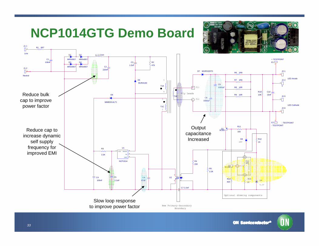
33
NCP1014GTG Demo BoardR1 4R7
D1
MRA4007
D2
MRA4007D3
MRA4007
D4
MRA4007
J2-5
LED Cathode
1
R14820
R121K
R247K
R15
1K
T1C
E2- TESTPOINT
1
R6 1R8
C1100nF
C2220nF
L1 2.7mH
C4100nF
C5
2.2uF
Q1BC857
T1A
R11
100
Optional dimming components
T1B
5.1V
D8
C7 2.2nF
+C81000uF
+ C91000uF
J1-1
Line
1
24V
J1-2
Neutral
1
Q2BC846
R9 10R
R8 10R
3
2
C647uF D9
D5MURA160
R4200
U1
NCP1014
VCC1
FB2
DRAIN 3
GND4
1
4
Off
boar
d
C31.5nF
R3
3.3K
FL2
FL1
R52.2K
U21
234
Fly Leads
R7 1R8
8mm Primary-Secondary Boundary
J2-1
1
1
J2-6
- TESTPOINT
1
D7 MURS320T3
D6
MMBD914LT1
R1010K
C1010nF
E1+ TESTPOINT
1
R1310K
J2-2LED Anode
1
Slow loop responseto improve power factor
Reduce bulkcap to improvepower factor
Reduce cap toincrease dynamic
self supply frequency for improved EMI
Output capacitance Increased
34
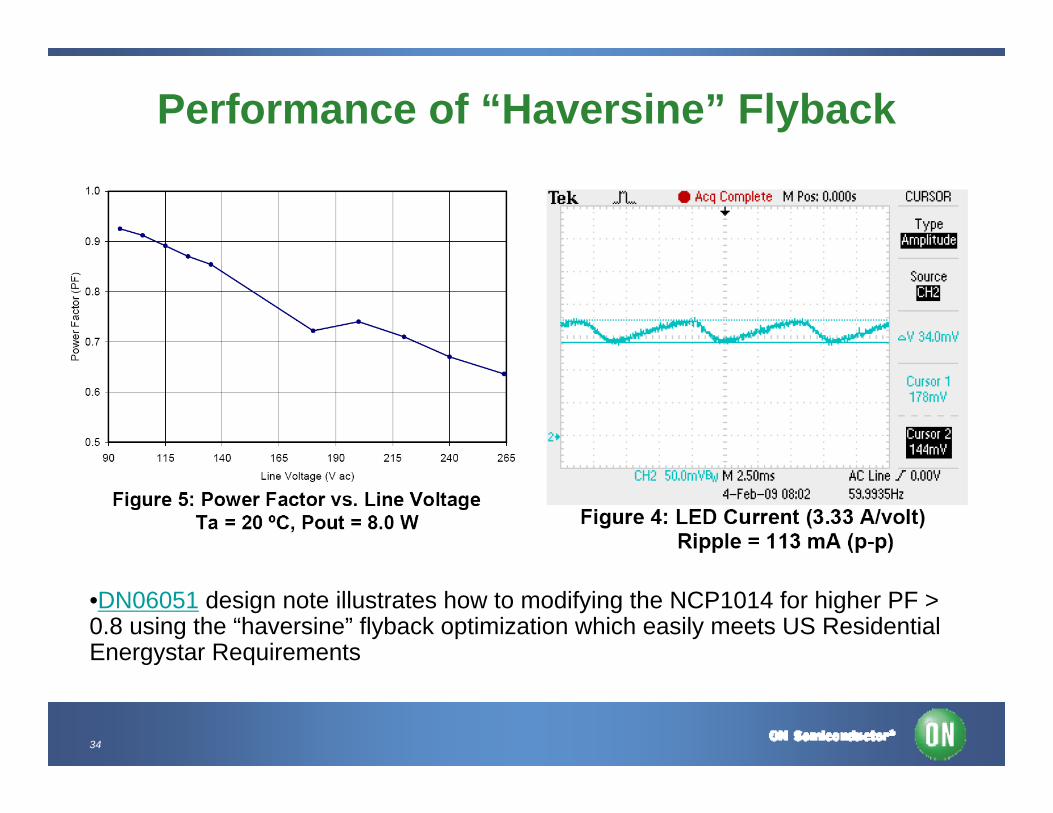
Performance of “Haversine” Flyback
•DN06051 design note illustrates how to modifying the NCP1014 for higher PF > 0.8 using the “haversine” flyback optimization which easily meets US Residential Energystar Requirements
35
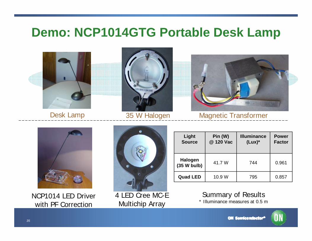
Demo: NCP1014GTG Portable Desk Lamp
Desk Lamp Magnetic Transformer
4 LED Cree MC-E Multichip Array
35 W Halogen
NCP1014 LED Driverwith PF Correction
795
744
Illuminance(Lux)*
0.96141.7 WHalogen(35 W bulb)
0.857 10.9 WQuad LED
PowerFactor
Pin (W)@ 120 Vac
Light Source
Summary of Results* Illuminance measures at 0.5 m
36
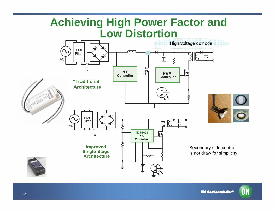
Achieving High Power Factor and Low Distortion
Secondary side controlis not draw for simplicity
High voltage dc node
NCP1652PFC
Controller
37
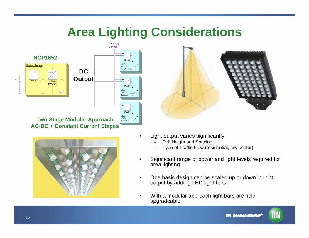
Area Lighting Considerations
• Light output varies significantly– Poll Height and Spacing– Type of Traffic Flow (residential, city center)
• Significant range of power and light levels required for area lighting
• One basic design can be scaled up or down in light output by adding LED light bars
• With a modular approach light bars are field upgradeable
LEDModulew/ CCR
PWM
DimmingControl
LEDLampw/CCR
PWM
LEDLampw/CCR
PWM
Power Supply
PFC IsolatedDC-DC
AC
Two Stage Modular ApproachAC-DC + Constant Current Stages
NCP1652
DCOutput
38
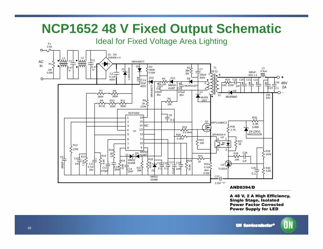
NCP1652 48 V Fixed Output SchematicIdeal for Fixed Voltage Area Lighting
R16
100, 1/2W
1
3 2
4
+
_
NCP1652 90 Watt LED Supply 48V, 2A Out, 90-265VAC Input
ACIn
48V2A
F12.5A
C1 C2L1
R1T1
3.3uH
12345
678 9
10111213141516
L2
L3
D1 - D41N5406 x 4
0.47"X"
0.47"X"1M
0.5W0.1uF400V
C3
D5
MRA4007T
1.5K
E440
AZ1R2560K0.5W
C422uF400V
D6
D7 D8
Z2
Z3
NCP1652
U1
U2
U3
Q1
2K 100
100
R3
R4
R5R8
R7 R6
R9 R10 R11
R12
R13 R14
R15
R17
R18 R19R20
R21
R22
R23
R24
R25
R26
R27
R28R29
R30
C5 C6
C7
C8
C9 C10
C11C12 C13
C14
C15 C16 C17 C18
C19 C20 C21 C22
C23
C24
C26
C25TL431A
10K
3.3 ohm
10
0.1 0.1
24K 1uF
102K
5.6K
2.7K
1K
0.1
100,63V
680uF,63V x 3
MMSZ5248B
MMSZ5245B
D9 MMSD4148T
MURS120T
MURS160T
1/2W
C27
2.2nF "Y"
36K3W 100nF
400V
SPP11N80C3
100uF35v
470uF35V
0.1u
F
76.8
K
49.9
K
39K10nF
100K
33nF
2.2K
470pF
7.32
K
8.6K
1nF
+
4.7uF25V
0.10ohm0.5W
680p
F
365K 365K
365K332K30.1K
Notes:
1. Crossed schematic lines are not connected.2. Heavy lines indicate power traces/planes.3. Z2/D9 is for optional OVP (not used).4. L1 is Coilcraft BU10-1012R2B or equivalent.5. L2 is Coilcraft P3221-AL or equivalent.6. L3 is Coilcraft RFB0807-3R3L or equivalent.7. Q1 and Q2 will require small heatsinks.
SFH615A-4
1
2
5
61nF
0.11nF
0 ohm
NC
0.1
(6:1)
D10
MR
A400
7T
D11
MMSD4148T
MUR860
R31
3.3K1/4W
Z4 (24V)MMSZ5252B
27K
8
11
39
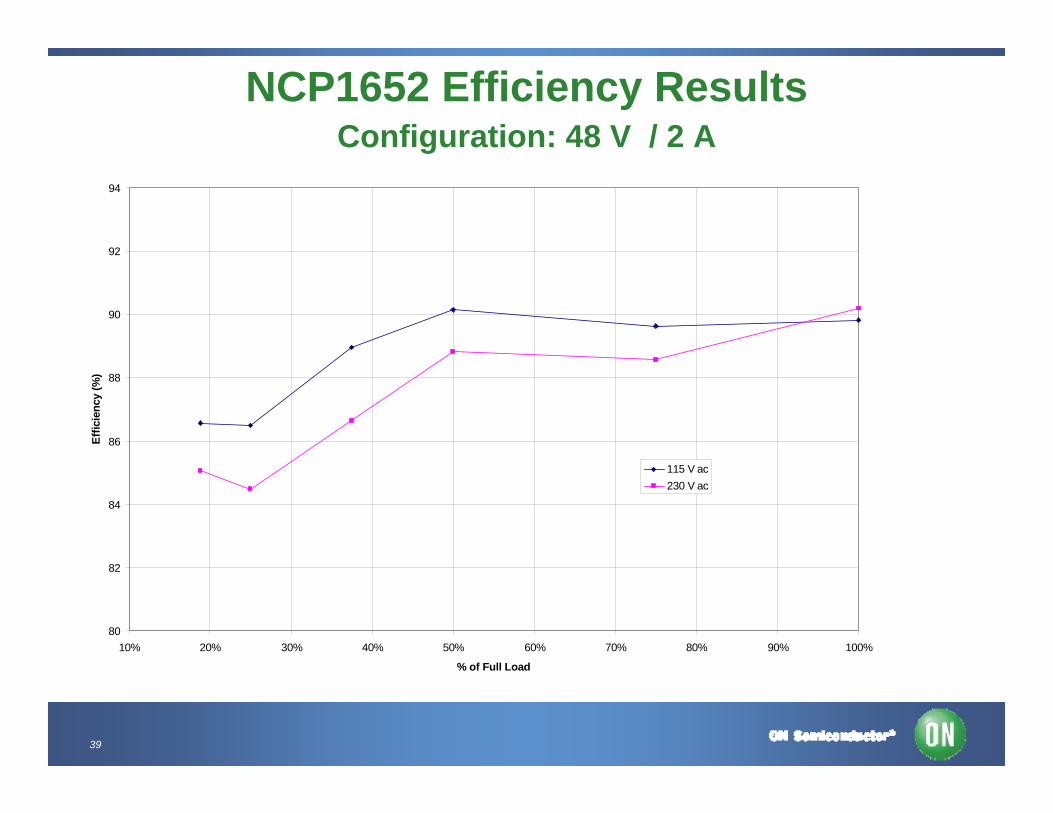
NCP1652 Efficiency ResultsConfiguration: 48 V / 2 A
80
82
84
86
88
90
92
94
10% 20% 30% 40% 50% 60% 70% 80% 90% 100%
% of Full Load
Effic
ienc
y (%
)
115 V ac230 V ac
40
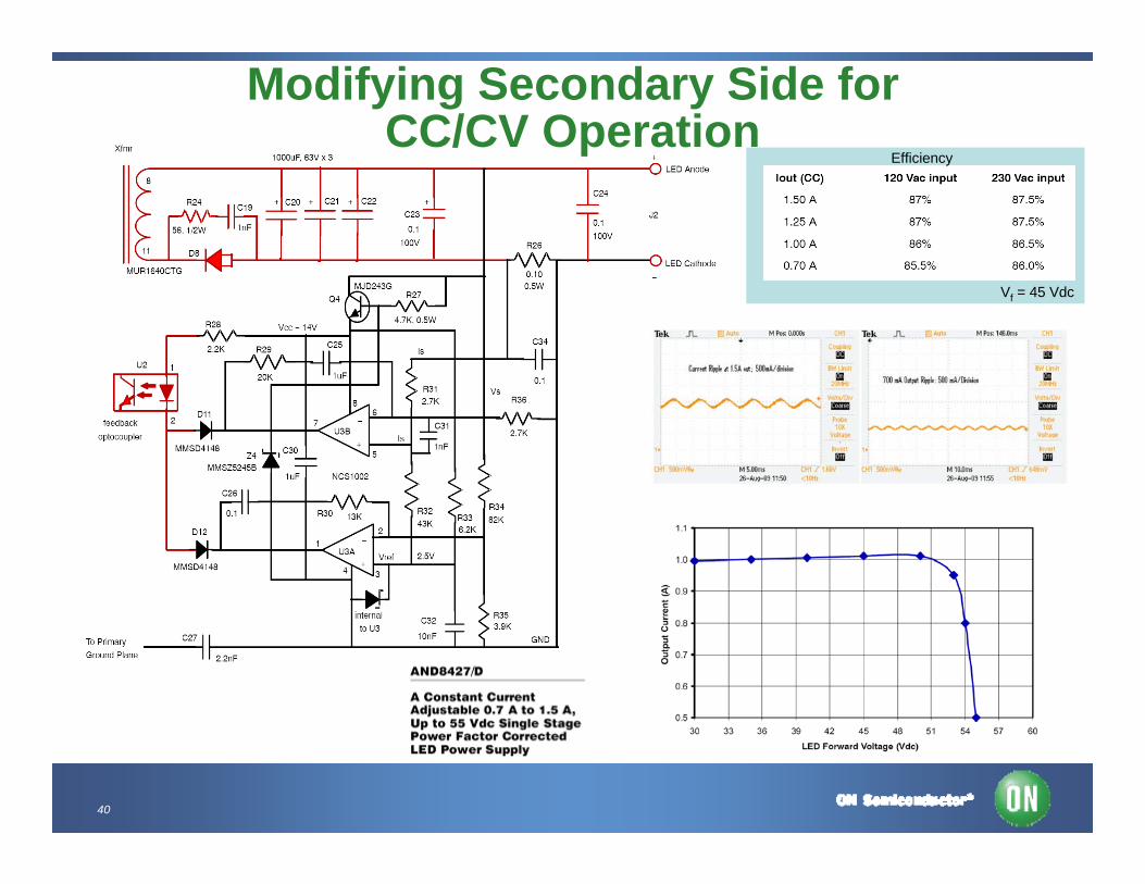
Modifying Secondary Side for CC/CV Operation
Vf = 45 Vdc
Efficiency
41
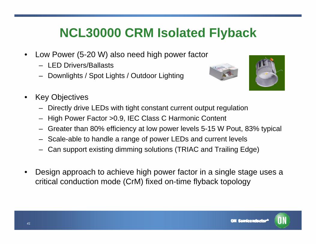
NCL30000 CRM Isolated Flyback• Low Power (5-20 W) also need high power factor
– LED Drivers/Ballasts– Downlights / Spot Lights / Outdoor Lighting
• Key Objectives– Directly drive LEDs with tight constant current output regulation– High Power Factor >0.9, IEC Class C Harmonic Content– Greater than 80% efficiency at low power levels 5-15 W Pout, 83% typical– Scale-able to handle a range of power LEDs and current levels– Can support existing dimming solutions (TRIAC and Trailing Edge)
• Design approach to achieve high power factor in a single stage uses a critical conduction mode (CrM) fixed on-time flyback topology
42
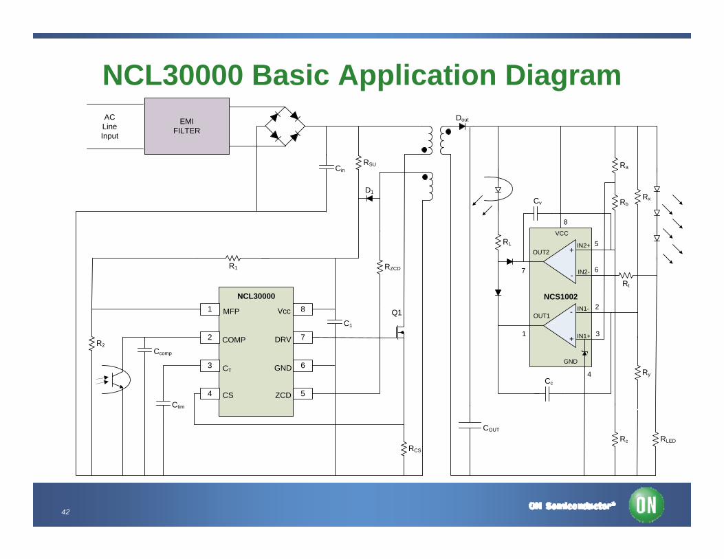
NCL30000 Basic Application Diagram
Q1
EMI FILTER
1
2
3
4
8
7
6
5
Cin
RCS
D1
C1
Ccomp
Ctim
Ry
RLED
RZCD
RL
R2
R1
RSU
MFP
COMP
Vcc
DRV
GND
ZCD
CT
CS
AC Line Input
Dout
COUT
Rc
Rt
Ra
RbRx
GND
4
3
2
1
7
8
5
6
IN1+
NCS1002IN1-
IN2-
IN2+
OUT1
OUT2
VCC
NCL30000
+
-
+
-
Cc
Cv
43
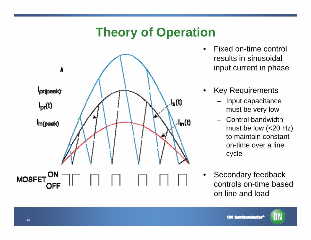
Theory of Operation• Fixed on-time control
results in sinusoidal input current in phase
• Key Requirements– Input capacitance
must be very low– Control bandwidth
must be low (<20 Hz) to maintain constant on-time over a line cycle
• Secondary feedback controls on-time based on line and load
44
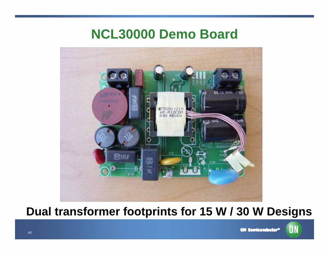
NCL30000 Demo Requirements • Intended to supply 350 mA and drive a wide range of LEDs (4-15) LED
driver applications. Component selections to support 700 mA or higher output current
• Reference design is targeting <20 W with this transformer, board can also support larger transformer for higher power
• Scalable solution for different power levels– 115 Vac Version - 90-130 Vac– 230 Vac Version 180-265 Vac– 90 – 305 Vac – Extended universal included 277 Vac - no Triac control
• For Triac Dimming, on time has to be adjusted for a specific number of LEDs to achieve best dimming performance. Default is 12 LEDs
• Robust Protection– Open LED, Shorted Output, Overload
45
NCL30000 Demo Board
Dual transformer footprints for 15 W / 30 W Designs
46
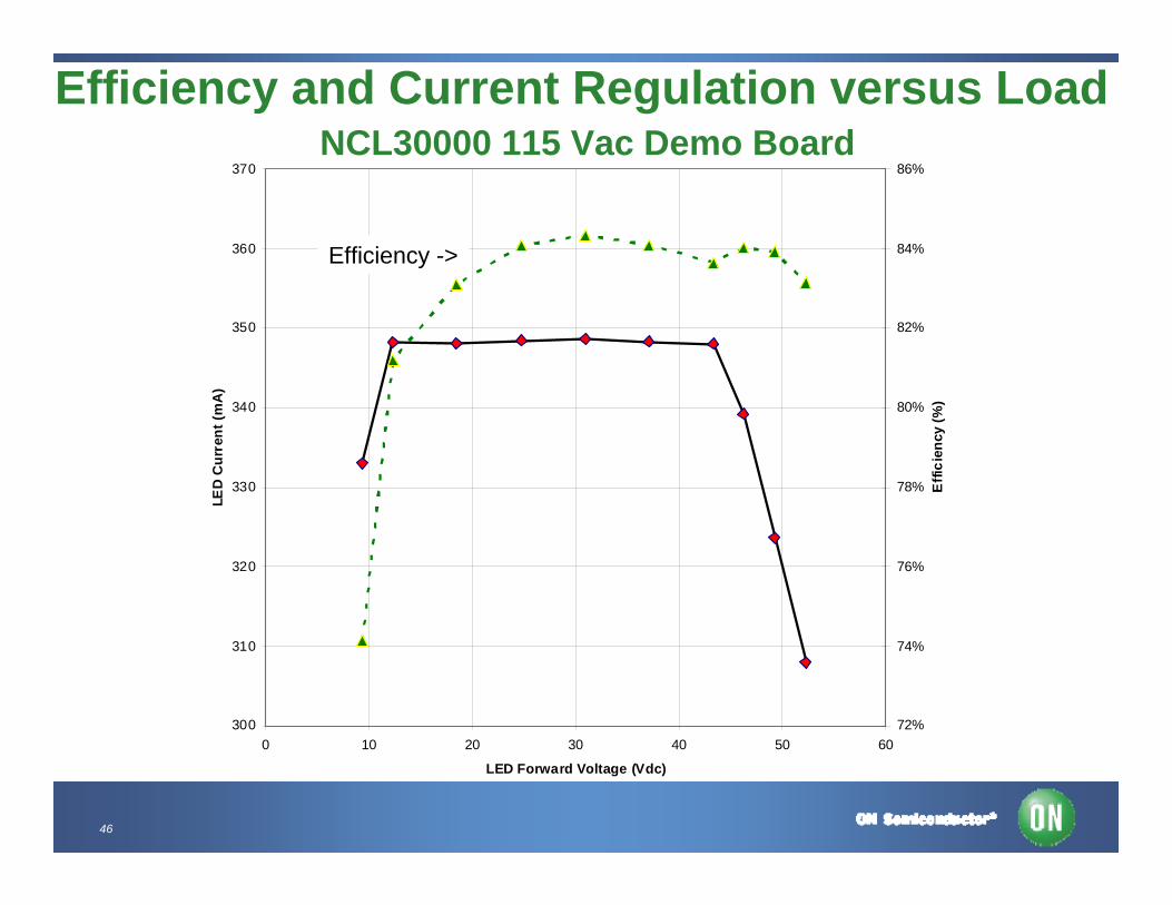
Efficiency and Current Regulation versus LoadNCL30000 115 Vac Demo Board
300
310
320
330
340
350
360
370
0 10 20 30 40 50 60
LED Forward Voltage (Vdc)
LED
Cur
rent
(mA
)
72%
74%
76%
78%
80%
82%
84%
86%
Effi
cien
cy (%
)
Efficiency ->

47
4
5
6
7
8
9
10
11
12
13
14
90 95 100 105 110 115 120 125 130 135
Input Voltage (Vac)
Inpu
t Cur
rent
TH
D (%
)
0.9
0.91
0.92
0.93
0.94
0.95
0.96
0.97
0.98
0.99
1
Pow
er F
acto
r (PF
)
THDPower Factor
Power Factor and Harmonic DistortionNCL30000 115 Vac Demo Board
48
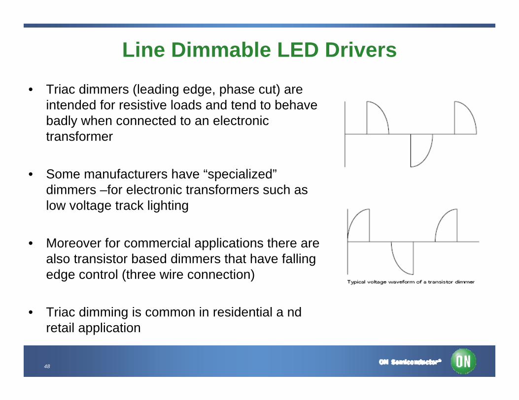
Line Dimmable LED Drivers
• Triac dimmers (leading edge, phase cut) are intended for resistive loads and tend to behave badly when connected to an electronic transformer
• Some manufacturers have “specialized”dimmers –for electronic transformers such as low voltage track lighting
• Moreover for commercial applications there are also transistor based dimmers that have falling edge control (three wire connection)
• Triac dimming is common in residential a ndretail application
49
Matching LED Driver to Dimmer
•A typical switch mode power supply feedback system will attempt to maintain constant output over a wide range of input voltage by increasing duty cycle or in this case on time
•For line dimming, LED current should reduce proportionately to reduction of the RMS input voltage
•The maximum on time is set to limit the power at the nominal LED string power
•During dimming, the controller will not be able to increase on time, so natural dimming of the LED occurs in a predictable manner
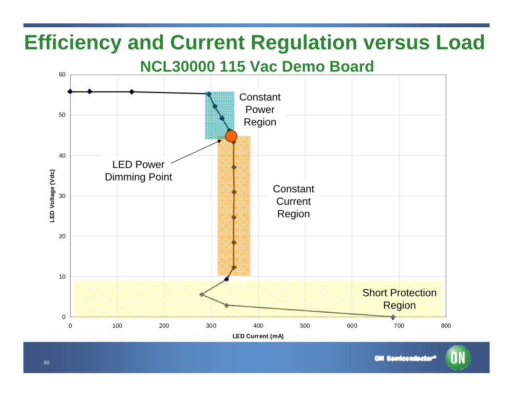
50
Efficiency and Current Regulation versus LoadNCL30000 115 Vac Demo Board
0
10
20
30
40
50
60
0 100 200 300 400 500 600 700 800
LED Current (mA)
LED
Vol
tage
(Vdc
)
ConstantCurrentRegion
ConstantPowerRegion
LED PowerDimming Point
Short ProtectionRegion

51
NCL30000 350 mA Isolated Flyback 115 Vac / 12 LED / Triac Dimming Version
0
50
100
150
200
250
300
350
400
20 30 40 50 60 70 80 90 100 110 120 130 140
Input Voltage (Vac)
LED
Cur
rent
(mA
)
10%
20%
30%
40%
50%
60%
70%
80%
90%
Effic
ienc
y
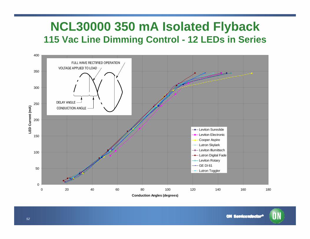
52
NCL30000 350 mA Isolated Flyback115 Vac Line Dimming Control - 12 LEDs in Series
0
50
100
150
200
250
300
350
400
0 20 40 60 80 100 120 140 160 180
Conduction Angles (degrees)
LED
Cur
rent
(mA
)
Leviton SureslideLeviton ElectronicCooper AspireLutron SkylarkLeviton IllumittechLutron Digital FadeLeviton RotaryGE DI 61Lutron Toggler
53
Comments on Triac and Transistor Dimming• As illustrated, dimming range is highly dependent on the
characteristics of the wall dimmer
• Triac dimmers were originally designed for incandescent lamps and presented a much higher load (4-5x higher) than a LED replacement down-light
• Unfortunately each manufacturer has different dimmer characteristics
• As LED lighting enters the mainstream we would expect dimmer manufacturers to start optimizing their products to LEDs
54
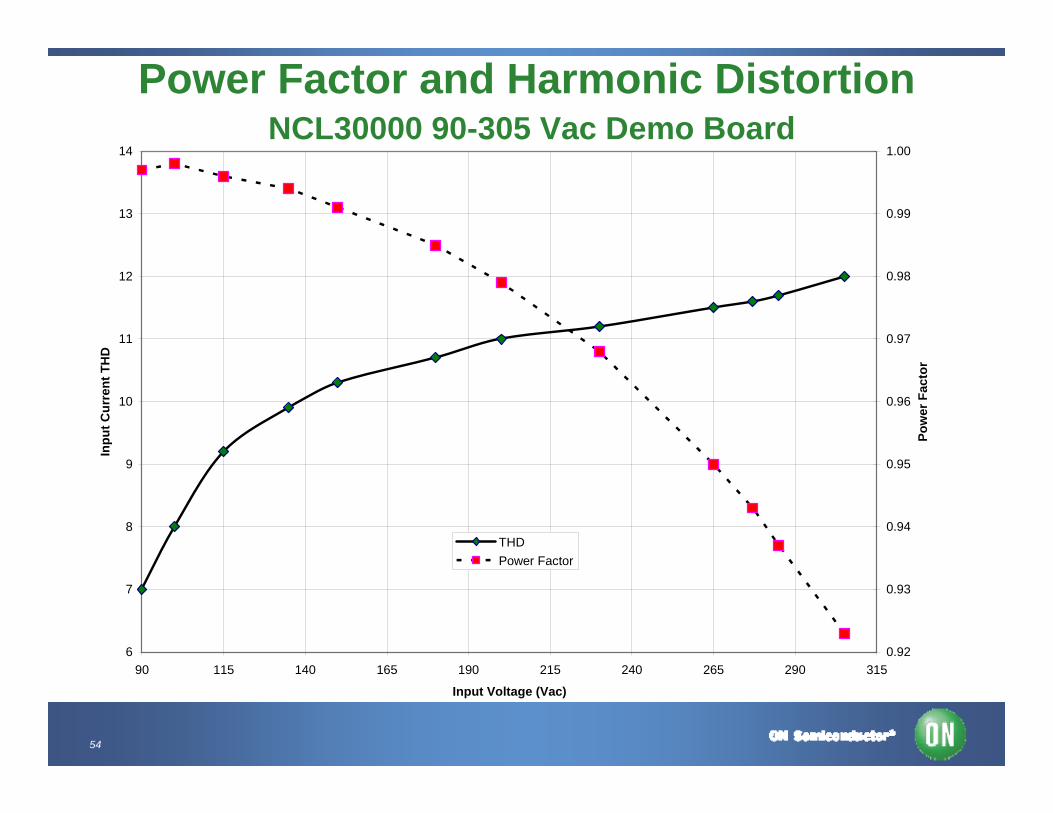
6
7
8
9
10
11
12
13
14
90 115 140 165 190 215 240 265 290 315
Input Voltage (Vac)
Inpu
t Cur
rent
TH
D
0.92
0.93
0.94
0.95
0.96
0.97
0.98
0.99
1.00
Pow
er F
acto
r
THDPower Factor
Power Factor and Harmonic DistortionNCL30000 90-305 Vac Demo Board
55
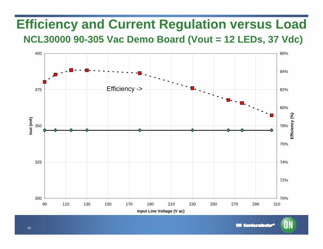
300
325
350
375
400
90 110 130 150 170 190 210 230 250 270 290 310
Input Line Voltage (V ac)
Iout
(mA
)
70%
72%
74%
76%
78%
80%
82%
84%
86%
Effic
ienc
y (%
)
Efficiency and Current Regulation versus LoadNCL30000 90-305 Vac Demo Board (Vout = 12 LEDs, 37 Vdc)
Efficiency ->
56
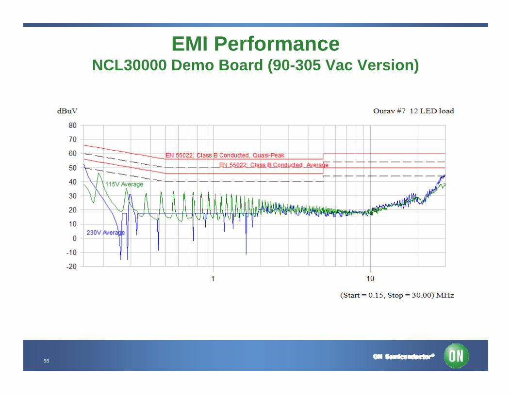
EMI PerformanceNCL30000 Demo Board (90-305 Vac Version)
57
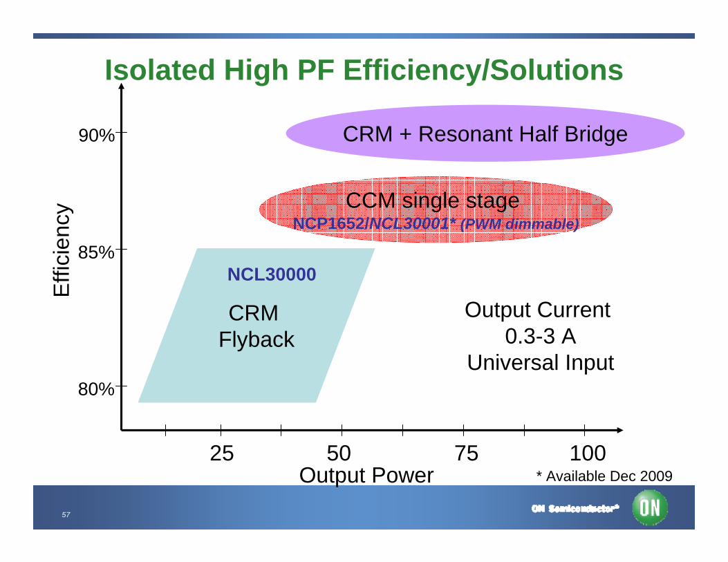
Isolated High PF Efficiency/Solutions
CRM + Resonant Half Bridge
CCM single stage NCP1652/NCL30001* (PWM dimmable)
85%
80%
90%
25 50 75 100Output Power
Effi
cien
cy
CRM Flyback
Output Current 0.3-3 A
Universal Input
NCL30000
* Available Dec 2009
58
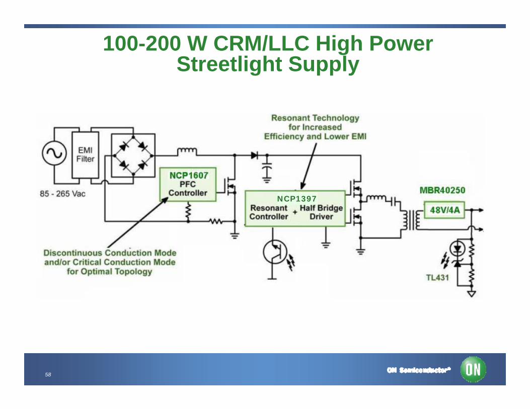
100-200 W CRM/LLC High Power Streetlight Supply
NCP1397
59
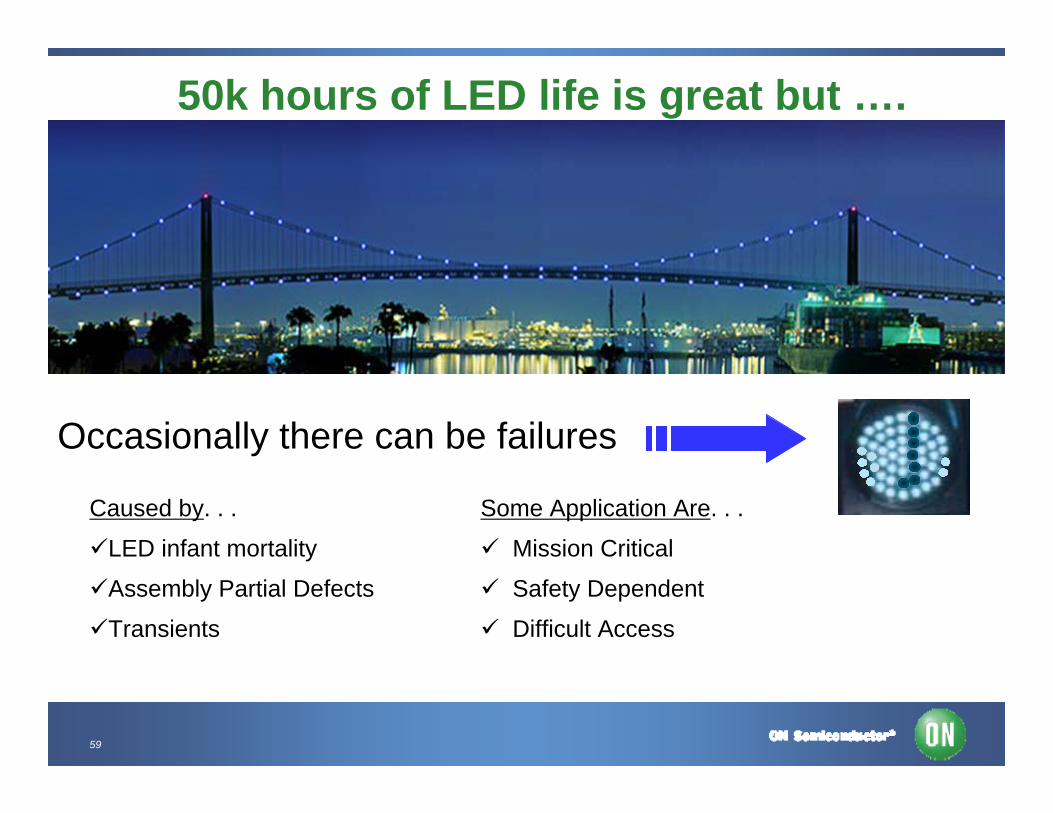
50k hours of LED life is great but ….
Occasionally there can be failures
Caused by. . .
LED infant mortality
Assembly Partial Defects
Transients
Some Application Are. . .
Mission Critical
Safety Dependent
Difficult Access
60
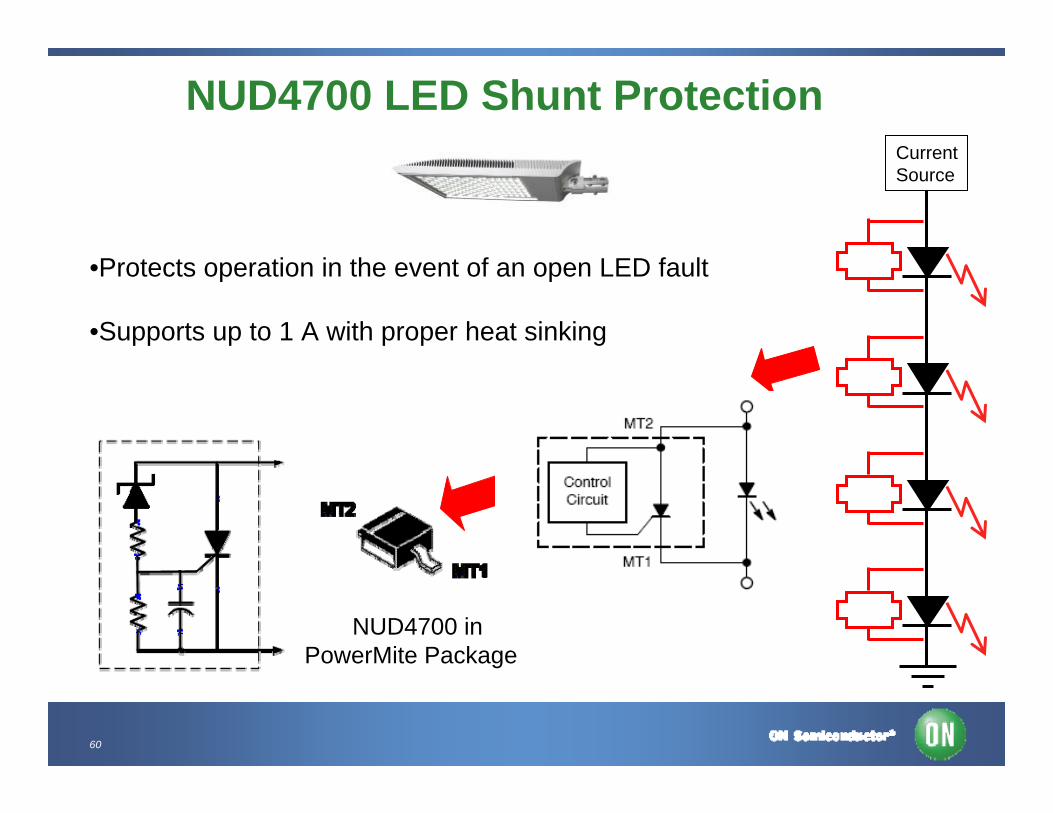
NUD4700 LED Shunt Protection
•Protects operation in the event of an open LED fault
•Supports up to 1 A with proper heat sinking
CurrentSource
NUD4700 inPowerMite Package
61
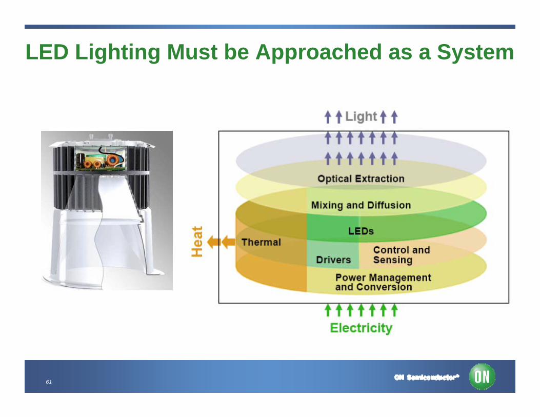
LED Lighting Must be Approached as a System
62
Conclusion• Offline LED power solutions continue to evolve in a rapid
manner as new LEDs are introduced
• Variety of offline solutions depending on power level, features, and performance
• ON Semiconductor has a complete portfolio of PFC and PWM controllers and converters to address range of LED power applications
• Visit the ON Semiconductor website to see what new reference designs are being introduced optimized for specific AC line powered LED applications

63
For More Information
• View the extensive portfolio of power management products from ON Semiconductor at www.onsemi.com
• View reference designs, design notes, and other material supporting the design of highly efficient power supplies at www.onsemi.com/powersupplies