overview of nasa glenn seal project · overview of nasa glenn seal project dr ... an update j....
TRANSCRIPT

OVERVIEW OF NASA GLENN SEAL PROJECT
Bruce M. Steinetz, Patrick Dunlap, and Margaret Proctor National Aeronautics and Space Administration
Glenn Research Center Cleveland, Ohio
Irebert Delgado
U.S. Army Research Laboratory Glenn Research Center
Cleveland, Ohio
Josh Finkbeiner National Aeronautics and Space Administration
Glenn Research Center Cleveland, Ohio
Jeff DeMange
University of Toledo Toledo, Ohio
Christopher C. Daniels
University of Akron Akron, Ohio
Shawn Taylor
University of Toledo Toledo, Ohio
Jay Oswald
J&J Technical Solutions, Inc. Cleveland, Ohio
Overview ofNASA Glenn Seal Project
Dr. Bruce M. SteinetzSeal Team of Mechanical Components Branch
Materials and Structures DivisionNASA Glenn Research Center
NASA Glenn hosted the Seals/Secondary Air System Workshop on November 8-9, 2005. At this workshop NASA and our industry and university partners shared their respective seal technology developments. We use these workshops as a technical forum to exchange recent advancements and “lessons-learned” in advancing seal technology and solving problems of common interest. As in the past we are publishing the presentations from this workshop in two volumes. Volume I will be publicly available and individual papers will be made available on-line through the web page address listed at the end of this presentation. Volume II will be restricted under International Traffic and Arms Regulations (I.T.A.R.). And Export Administration Regulations (E.A.R.)
NASA/CP—2006-214383/VOL1 45
https://ntrs.nasa.gov/search.jsp?R=20070003000 2018-07-03T22:15:26+00:00Z

NASA Glenn Research CenterSeal Team
Workshop AgendaTuesday, Nov. 8, Morning
Registration 8:00 a.m.–8:30 a.m.
Introductions 8:30-8:50 Introduction Dr. Bruce Steinetz, R. Hendricks/NASA GRCWelcome Dr. Rich Christiansen, Deputy Director/NASA GRC
Dr. Ted Keith, R&T Director, NASA GRC
Program Overviews and Requirements 8:50-10:20Overview of NASA’s Exploration Initiative Dr. Timothy Tyburski for Mr. Harry Cikanek/NASA GRCOverview of NASA’s Propulsion 21Project Ms. Mary Jo Long Davis/ NASA GRCOverview of NASA Glenn Seal Project Dr. Bruce Steinetz et al/NASA GRCOverview Comments Mr. Robert C. Hendricks/NASA GRC
Break 10:20 -10:35
Turbine Seal Development Session I 10:35-12:15Commercial Airplane Aero Seal Needs Mr. Chris Jasklowski/BoeingApplying Brush Seals To Steam Turbines Mr. Norm Turnquist, R. Chupp/GE Global Research CenterAdvanced Seal Rig Experiments & Analysis Mr. Roger Paolillo/Pratt and WhitneyComparison of Labyrinth, Annular, Brush, and Finger Seal Mr. Irebert Delgado/U.S. Army Res. Lab, M. Proctor/NASA GRC
Power Loss and Leakage CharacteristicsHigh Misalignment Carbon Seals: Progress Report Mr. Dennis Shaughnessy, L. Dobek/Pratt & Whitney
Lunch: OAI Sun Room 12:20-1:20
The first day of presentations included overviews of current NASA programs. Dr. Tyburski reviewed the goals and objectives of NASA’s new Exploration Initiative targeting both robotic and manned missions to the Moon, Mars and beyond. Ms. Mary Jo Long-Davis of the Ultra-Efficient-Engine Technology (UEET) project office, reviewed project plans and objectives of the Propulsion 21 project. Propulsion 21 is developing advanced turbine engine technologies aimed at reducing fuel burn, emissions, and noise using a consortium of Ohio organizations.
Dr. Steinetz presented an overview of NASA seal developments for both NASA’s aeronautic and space projects. Mr. Hendricks presented a call-to-action for the community to address the sobering fact that the world is consuming greater oil resources than it is discovering. Though improved sealing technology can play a role in reducing fuel burn by improving engine efficiency, there is a need to start addressing alternate energy sources to help ward-off a future energy crisis.
Mr. Jasklowski of Boeing presented current pylon/nacelle to engine seal challenges and needs. Dr. Chupp presented an overview of recent successes that GE Energy Systems has had in applying advanced seals including brush and abradable seals to steam turbines. Mr. Paollilo presented an overview of several novel labyrinth seal geometries being evaluated both analytically and experimentally. Mr. Delgado compared labyrinth, annular, brush, and finger seal power loss and leakage characteristics. Mr. Shaughnessy of P&W presented an overview of the work P&W and Stein Seal are doing to develop high misalignment carbon seals for a geared fan application.
NASA/CP—2006-214383/VOL1 46
NASA Glenn Research CenterSeal Team
Workshop AgendaTuesday, Nov. 8, Afternoon
Turbine Seal Development Session II: 1:20-2:40 Active Control
Advanced Thermal HPT Clearance Control and Mr. Wojciech Sak/General Electric Aircraft EnginesHPT Blade Cooling for Leap 56
Test Rig for Active Turbine Blade Tip Clearance Mr. Shawn Taylor/Univ of Toledo, B. Steinetz/NASA GRCControl Concepts: An Update J. Oswald/J&J Technical Sol., J. Decastro/QSS, K. Melcher/NASA
Microwave Blade Tip Sensor Development: An Update Mr. Jon Geisheimer/Radatech Inc. System-Level Design of a Shape Memory Alloy Actuator for Mr. Jon Decastro/QSS, K. Melcher, R. Noebe/NASA GRC
Active Clearance Control in the High-Pressure Turbine
Break 2:40-3:00
Turbine Seal Development Session III 3:00-5:00Further Development of Compliant Foil Seals <withdrawn> Dr. Hooshang Heshmat/Mohawk Innovative Tech.Rotating Brush Seal Design for an Advanced Engine Mr. Gary Holloway, S. Krawiecki/ Diversitech
J. Mehta/TK EngineeringPressure Actuated Leaf Seals for Improved Mr. Clayton Grondahl/CMG Tech, LLC
Turbine Shaft SealingBrush Seals: Feedback from the Field Mr. Chuck Trabert, T. O'Meara, J. Short/PerkinElmerProgress Review of the Finger Seal Development Activities Dr. Jack Braun, H. Pierson, D. Deng, H. Li/Univ. of AkronImproved Sealing Performance through Precise Assembly Mr. Robert Lee/Axiam
Adjourn
Group Dinner: Kristofer’s Restaurant 6:15-?
Turbine engine studies have shown that reducing high pressure turbine (HPT) blade tip clearances will reduce fuel burn, lower emissions, retain exhaust gas temperature margin and increase range. Mr. Sak presented an overview of GE’s approach for a fast acting thermal active clearance control system. Mr. Taylor presented an overview of the new Active Clearance Control Test rig aimed at demonstrating advanced ACC kinematic systems, actuators, control methods, and sensors. Mr. Taylor presented recent leakage and clearance control data collected using the test rig. Mr. Geisheimer of Radatech presented an overview of their microwave blade tip sensor development efforts. Microwave tip sensors show promise of operation in the extreme gas temperatures present in the HPT location. Mr. DeCastro presented a design of a shape memory alloy (SMA) actuator for active clearance control in the high-pressure turbine. Shape memory alloy actuators are being considered to reduce system weight of future ACC systems.
Mr. Holloway presented the design of a rotating carbon fiber brush seal being developed for future bearing compartments for either co- or counter-rotating intershaft locations. Mr Grondahl presented an overview of a new pressure actuated leaf seal. This concept employs pressure actuation to cause metal laminates to flex radially toward the shaft at operating pressures but spring away for start-up and shut-down to minimize the chances of seal-to-rotor rub. Mr. Trabert of Perkin Elmer presented leakage data of brush seals both before and after 3000 hrs of engine operation. The brush seals showed very similar leakage performance after these extended periods of use. Dr. Braun presented investigations into a non-contacting finger seal under development by NASA GRC and University of Akron. Mr. Lee presented unique equipment that is used for precision alignment of rotors and seals. Precision alignment allows tighter sealing, reduced oil leakage, and helps reduce balance weight addition through preferred part orientation during assembly.
NASA/CP—2006-214383/VOL1 47
NASA Glenn Research CenterSeal Team
Workshop AgendaWednesday, Nov. 9 Morning
Registration at OAI 8:00-8:30
Space Systems Development 8:30-10:10Future Space Vehicle Docking/Berthing Mechanism and Mr. James Lewis (or designee)/NASA Johnson Space Center
Seal Needs: An UpdateFalcon/Common Aero Vehicle Program Objectives Mr. Brian Zuchoswski, D. Johnson/ Lockheed-Martin
And Seal ChallengesOverview of NASA’s In-Situ Resource Utilization Project Mr. Kurt Sacksteder, Diane Linne/ NASA GRC
And Seal Challenges
Break 10:10-10:25
Structural Seal Development Session I 10:25-12:00An Update on High Temperature Structural Seal Mr. Patrick Dunlap, B. Steinetz/NASA GRC,
Development at NASA GRC J. Demange/U. of ToledoHigh Temperature Testing of the X-37 Flaperon Seals Mr. Jeff Demange/U. of Toledo, P. Dunlap/NASA GRCHigh Temperature Gaskets and Sealants for Dr. Jay Singh, Tara Shpargel, QSS Group/NASA GRC
Re-entry and Hypersonic EnvironmentsHigh Temperature Metallic Seal Development: An Update Dr. Amit Datta, Advanced Components and Materials
Mr. Greg More Parker Co.
Lunch OAI Sun Room 12:00-1:00
NASA is developing a standardized system for docking and berthing for future exploration system vehicles such as the Crew Exploration Vehicle. Mr. Lewis leads the Advanced Docking and Berthing project at NASA JSC but due to another time commitment asked Dr. Steinetz to present the goals and objectives of this project. DARPA and the Air Force (with support from NASA) are developing a hypersonic payload delivery system that can reach Mach 10 conditions. Mr. Zuchowski presented an overview of project goals and identified extensive vehicle seal challenges. Mr. Sacksteder presented an overview of NASA’s plans to develop In-Situ Resource Utilization techniques to enable future astronauts to harvest resources from either the Moon (e.g. ice) and Mars (e.g. CO2) to allow astronauts to live off the land to extend mission duration.
Mr. Dunlap presented an overview of the structural seal development activities underway for hypersonic systems (e.g. both propulsion systems and vehicles), re-entry vehicles (e.g. X-vehicles and CEV), and future docking and berthing systems. Mr. DeMange presented control surface (e.g. hinge-line) seal development efforts underway at GRC for future re-entry vehicles –such as the X-37. Dr. Singh reviewed materials development for Shuttle repair strategies. These include both high temperature materials for leading edge crack repair and high temperature gaskets. Mr. More of Parker presented recent progress in developing higher temperature metal seals (e.g. E- or other) that incorporate single-crystal blade alloy finger preloaders capable of 1600+°F operation.
NASA/CP—2006-214383/VOL1 48

NASA Glenn Research CenterSeal Team
Workshop AgendaWednesday, Nov. 9, Afternoon
Structural Seal Development Session II 1:00-2:30Investigations of Shuttle Main Landing Gear Mr. Josh Finkbeiner, et al/NASA GRC
Door Environmental SealsElastomeric Seal Development for the Advanced Dr. Chris Daniels/U. of Akron, P. Dunlap, B. Steinetz/NASA GRC
Docking / Berthing SystemSpace Environments Effects on Materials and Dr. Sharon Miller, Dr. Bruce Banks/NASA GRC
GRC's Test CapabilitiesMetallic Seal Development for Adv. Docking/Berthing System Mr. Jay Oswald/J&J Tech. Sol., C. Daniels/U. of Akron
P. Dunlap, B. Steinetz/NASA GRC
General Interest 2:30-3:00Mapping Technological Opportunities Mr. Dana Clarke/Applied Innovation Alliance, LLC
- Evolving a Labyrinth Seal -
Tour of NASA Seal Test Facilities 3:15-4:15
Adjourn
In preparation for Shuttle Return to Flight, NASA JSC requested that NASA GRC assist in performing tests with the Shuttle Main Landing Gear Door seals. Mr. Finkbeiner presented compression and flow results for Shuttle main landing gear door seals. Tests performed and observations made aided in reducing seal compressions loads assisting JSC and KSC in closing the Shuttle main landing gear doors for flight.
Dr. Daniels and Mr. Oswald presented test results for elastomeric and metal seals being considered for future advanced docking and berthing systems that JSC is developing for future space vehicle docking and berthing needs. Dr. Banks presented an overview of space environments potentially damaging effects on materials and summarized GRC’s atomic and ultra violet (UV) test capabilities being used to evaluate material candidates for the Docking and Berthing project.
Mr. Clark presented techniques his company uses- inspired by the theory of inventive problem solving (TRIZ) - to map technological opportunities by identifying how a technology (e.g. seals) evolve over time.
NASA/CP—2006-214383/VOL1 49

NASA Glenn Research CenterSeal Team
NASA Glenn Seal Team
Seal Team Leader: Bruce SteinetzMechanical Components Branch/RXM
Turbine Seal DevelopmentDevelop non-contacting, low-leakage turbine sealsMargaret Proctor: Principal Investigator/POCIrebert Delgado, Dave Fleming, Joe Flowers
Structural Seal DevelopmentDevelop resilient, long-life, structural seals for extreme environmentsPat Dunlap: Principal InvestigatorJeff DeMange, Josh Finkbeiner, Jay Oswald, Malcolm Robbie, Art Erker, Joe Assion
Exploration System SealsAdvanced Docking/Berthing, CEV, Aerocapture, Fuel Cell Seals,Pat Dunlap; Chris Daniels: Co-Principal InvestigatorsJay Oswald, Josh Finkbeiner, Art Erker, Joe Assion
Turbine Clearance ManagementDevelop novel approaches for blade-tip clearance control.Shawn Taylor: Principal InvestigatorJim Smialek (RX), Malcolm Robbie, Art Erker
The Seal Team is divided into four primary areas. The principal investigators and supporting researchers for each of the areas are shown in the slide. These areas include turbine seal development, structural seal development, clearance management, and seals for NASA’s Exploration Systems Initiative. The first area focuses on high temperature, high speed shaft seals for turbine engine secondary air system flow management. The structural seal area focuses on high temperature, resilient structural seals required to accommodate large structural distortions for both space- and aero-applications.
Our goal in the clearance management project is to develop advanced approaches and technologies for minimizing blade-tip clearances and leakage. We are planning on applying either rub-avoidance or regeneration clearance control concepts (including smart structures and materials) to promote higher turbine engine efficiency and longer service lives.
We are also contributing seal expertise in a range of emerging areas for NASA’s Exploration Initiative. These include seal developments and studies for the advanced docking and berthing, crew exploration vehicle (CEV), aerocapture, and fuel cell projects.
NASA/CP—2006-214383/VOL1 50

Turbine Engines: Seal Challenges and Projects Supported
NASA/CP—2006-214383/VOL1 51

NASA Glenn Research CenterSeal Team
Turbine Shaft Seals: Challenges and Goals
• Challenges:– Minimize leakage to enable: reduced fuel consumption and emissions
– High temperatures: up to 1500°F
– High speeds up to 1500 fps
– Moderate pressure 250 psi
– Operate with little or no wear for long life 3-10,000 hrs
– Minimize heat generation
• GRC non-contacting seal project goal:– Develop non-contacting seal designs and design methods to enable low-
leakage and virtually zero wear:
» Demonstrate hydrodynamic and/or hydrostatic lift geometries.
» Demonstrate under engine simulated operating conditions
» Transfer technology to private sector
Designers of future turbine engine seals face ever increasing challenges (Steinetz and Hendricks, 1998) including high temperature, high speed operation, the need to operate for long lives with little or no wear while minimizing heat generation. One of NASA GRC’s turbine engine seal goals is to develop non-contacting seal designs that incorporate hydrostatic and/or hydrodynamic lift geometries. Seals under development will be fabricated and tested in NASA GRC’s high temperature, high speed seal rig to assess their performance under engine simulated conditions.
NASA/CP—2006-214383/VOL1 52

NASA Glenn Research CenterSeal Team
NASA GRC Non-Contacting Finger Seal Design
Basic Features• Downstream: Lift pads on
downstream fingers allows tracking of rotor motion
• Upstream: Fingers block flow between downstream fingers and move with downstream fingers. Clearance between fingers and rotor prevent wear.
Additional FeaturesHerringbone pattern on rotor enables pressure build-up underneath seal pads for additional lift-off during disk rotation – if required.Laser etching processing technique shows feasibility of applying herringbone lift-geometry on test rotor.
PerformanceSmall pad-to-shaft clearances promotes low leakage.Non-contacting operation promotes long-life
SEAL DAM
View of Low Pressure Lift Pad
CIRCUFERENTIALGROOVE
Front View
PH
US Patent No.: 6,811,154
Conventional finger seals like brush seals attain low leakage by operating in running contact with the rotor (Proctor, et al, 2002). The drawbacks of contacting seals include wear over time, heat generation, and power loss.
NASA Glenn has developed several concepts for a non-contacting finger seal. In one of these concepts the rear (low-pressure, downstream) fingers have lift pads (see see lower right figure) and the upstream (high pressure side) fingers are pad-less, and are designed to block the flow through the slots of the downstream fingers. The pressure-balance on the downstream-finger lift-pads cause them to lift. The front fingers are designed to ride slightly above the rotor preventing wear. Pressure acts to hold the upstream fingers against the downstream fingers. It is anticipated that the upstream/downstream fingers will move radially as a system in response to shaft transients. Though a small pin-hole leakage path exists between the inner diameter of the upstream fingers, the rotor, and the downstream fingers, this small pin-hole doesn’t cause a large flow penalty especially considering the anticipated non-contacting benefits of the overall approach.
A non-contacting finger seal based on the GRC patent (US Patent No.: 6,811,154 ) has been fabricated (see upper right figure) and will be tested in GRC’s turbine seal test rig. The seal will be tested against a rotor that has a herringbone lift geometry that is fashioned onto the rotor surface using a laser etching process. (see laser etch sample in lower middle photo).
NASA/CP—2006-214383/VOL1 53

NASA Glenn Research CenterSeal Team
Non-Contacting Finger Seal Investigations: University of Akron
Radial Displacement
Seal Dynamics & 2-D Solid Modeling
Fluid-Structure Interaction
Visualization
ROTOR SURFACE
FS MASS
FLUIDSTIFFNESS
FLUIDDAMPING
FINGERSTIFFNESS
y
x
Rotor
Seal
Dr. J. Braun and his team at the University of Akron are performing analyses and tests of this GRC concept through a cooperative agreement (Braun et al, 2003). University researchers developed an equivalent spring-mass-damper system to assess lift characteristics under dynamic excitation. Fluid stiffness and damping properties were obtained utilizing CFD-ACE+ (3-D Navier-Stokes code) and a perturbation approach. These stiffness and damping properties were input into the dynamic model expediting the solution for design purposes. Dr. Braun an expert in advanced visualization techniques has investigated the finger seal lift-off using unique lighting and measurement techniques during seal operation at ambient temperature using the Univ of Akron’s test rig. These measurements are providing useful insights into seal operation for design evolution.
More details can be found in Braun et al, 2006 in this Seal Workshop Proceedings. After feasibility tests are complete at the University, seals will be tested under high speed and high temperature conditions at NASA GRC.
NASA/CP—2006-214383/VOL1 54

Turbine Clearance Management
NASA/CP—2006-214383/VOL1 55
NASA Glenn Research CenterSeal Team
Motivation for Tip Clearance Control + Challenges
SOA Thermal Clearance Control
Active Clearance Control
Cruise(new engine)
Cruise(worn engine)
15-20 mil
30-50 mil ~5 mil
~5 mil
0-10 mil ~5 milblade
shroudTakeoff
(new engine)blade
shroud
The Problem:Clearances between the shroud and blade
tips vary over the operation and life of an engine. Wear and thermal erosion increases blade tip clearance.
Benefits of Clearance Control:• Increased engine efficiency & reduced SFC
(0.8-1% SFC)• Reduced NOx & CO emissions• Delayed rise in exhaust gas temperature
(EGT)
ACC System Challenges:
Temperature: Gas path - >2500°FCooling air - >1200°FCase - 600°F (w/ soak back)
Load/Response: Actuators must react ~2000 lbf move ~0.05” in 10 sec
Accuracy: Current Systems - 0.015-0.020-inGoal – <0.005-in
Size/Weight: Small, lightweight ACC systems requiredGoal current thermal systems (<100 lbs).
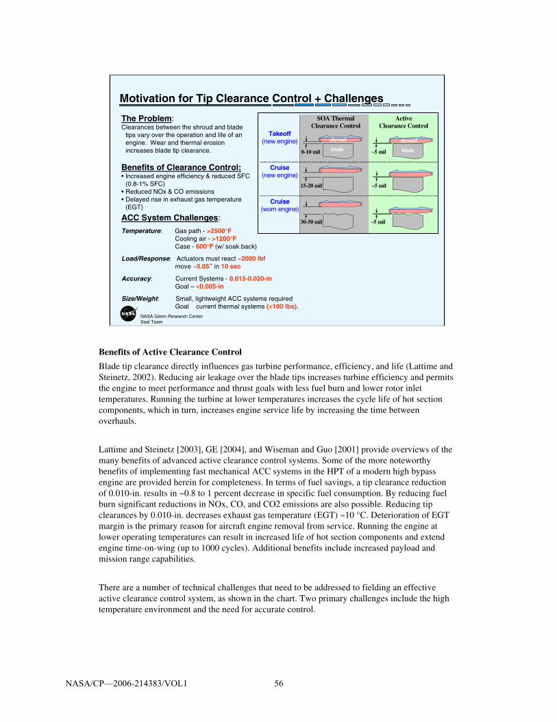
Benefits of Active Clearance Control
Blade tip clearance directly influences gas turbine performance, efficiency, and life (Lattime and Steinetz, 2002). Reducing air leakage over the blade tips increases turbine efficiency and permits the engine to meet performance and thrust goals with less fuel burn and lower rotor inlet temperatures. Running the turbine at lower temperatures increases the cycle life of hot section components, which in turn, increases engine service life by increasing the time between overhauls.
Lattime and Steinetz [2003], GE [2004], and Wiseman and Guo [2001] provide overviews of the many benefits of advanced active clearance control systems. Some of the more noteworthy benefits of implementing fast mechanical ACC systems in the HPT of a modern high bypass engine are provided herein for completeness. In terms of fuel savings, a tip clearance reduction of 0.010-in. results in ~0.8 to 1 percent decrease in specific fuel consumption. By reducing fuel burn significant reductions in NOx, CO, and CO2 emissions are also possible. Reducing tip clearances by 0.010-in. decreases exhaust gas temperature (EGT) ~10 °C. Deterioration of EGT margin is the primary reason for aircraft engine removal from service. Running the engine at lower operating temperatures can result in increased life of hot section components and extend engine time-on-wing (up to 1000 cycles). Additional benefits include increased payload and mission range capabilities.
There are a number of technical challenges that need to be addressed to fielding an effective active clearance control system, as shown in the chart. Two primary challenges include the high temperature environment and the need for accurate control.
NASA/CP—2006-214383/VOL1 56
NASA Glenn Research CenterSeal Team
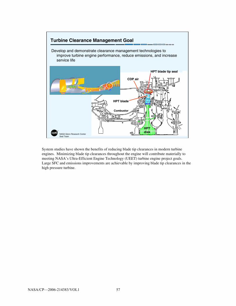
Turbine Clearance Management Goal
Develop and demonstrate clearance management technologies to improve turbine engine performance, reduce emissions, and increase service life
HPT blade
HPT disk
CDP air
HPT blade tip seal
Combustor
System studies have shown the benefits of reducing blade tip clearances in modern turbine engines. Minimizing blade tip clearances throughout the engine will contribute materially to meeting NASA’s Ultra-Efficient Engine Technology (UEET) turbine engine project goals.Large SFC and emissions improvements are achievable by improving blade tip clearances in the high pressure turbine.
NASA/CP—2006-214383/VOL1 57

NASA Glenn Research CenterSeal Team
Active Clearance Control Concept & Evaluation Test Rig
Purpose:• Evaluate ACC kinematic system +
actuator response and accuracy under appropriate thermal (to 1200°F) and pressure (to 120 psi) conditions.
• Evaluate clearance sensor response and accuracy
– Capacitance– Microwave
• Measure ACC system seal performance (leakage and wear) and identify mitigation strategies.
Heat Inputs:+ Radiant+ Air Supply
Chamber
Seal carrier assembly
ActuatorsGen 1: Stepper motorsGen 2: Servo-hydraulic
AdvancedClearance Sensors
NASA GRC is developing a unique Active Clearance Control (ACC) concept and evaluation test rig. The primary purpose of the test rig is to evaluate ACC kinematic systems, actuator concept response and accuracy under appropriate thermal (to 1200+F) and pressure (up to 120 psig) conditions. Other factors that will be investigated include:
•Actuator stroke, rate, accuracy, and repeatability
•System concentricity and synchronicity
•Component wear
•Secondary seal leakage
•Clearance sensor response and accuracy
The results of this testing will be used to further develop/refine the current system design as well as other advanced actuator concepts. More details regarding this test rig can be found in Taylor, et al 2006 (in this Seal Workshop Proceedings), Steinetz et al, 2005, and Lattime et al, 2003.
NASA/CP—2006-214383/VOL1 58

Exploration Systems:Seals Challenges and Projects Supported
NASA/CP—2006-214383/VOL1 59

NASA Glenn Research CenterSeal Team
Advanced Docking/Berthing System
What is the Advanced Docking and Berthing System (ADBS)?
System under development by JSC to:
• Provide gender-neutral (androgynous) interface permitting docking/berthing between any two space vehicles
• Reduce impact loads between two mating space craft. (e.g. Low Impact Docking System: LIDS)
• Become new Agency standard for docking/berthing systems.
Docking/BerthingSystem
ADBS
Interface Seal
In preparation for the Exploration Initiative, NASA has identified the need for a standard docking and berthing system to allow easy docking between space faring vehicles and platforms orbiting either Earth (e.g. the Space Station) the Moon or Mars. NASA Johnson is developing an advanced docking and berthing system (ADBS) that has several important features:
+ The system will be androgynous or gender-neutral permitting docking and berthing between any two space vehicles, giving NASA and the astronauts maximum mission planning flexibility.
+ Using a soft capture system, minimal loads will be imparted between systems minimizing potential for damage.
For additional information regarding the ADBS project and system, see James Lewis’presentation in this Workshop Proceedings.
NASA/CP—2006-214383/VOL1 60
NASA Glenn Research CenterSeal Team
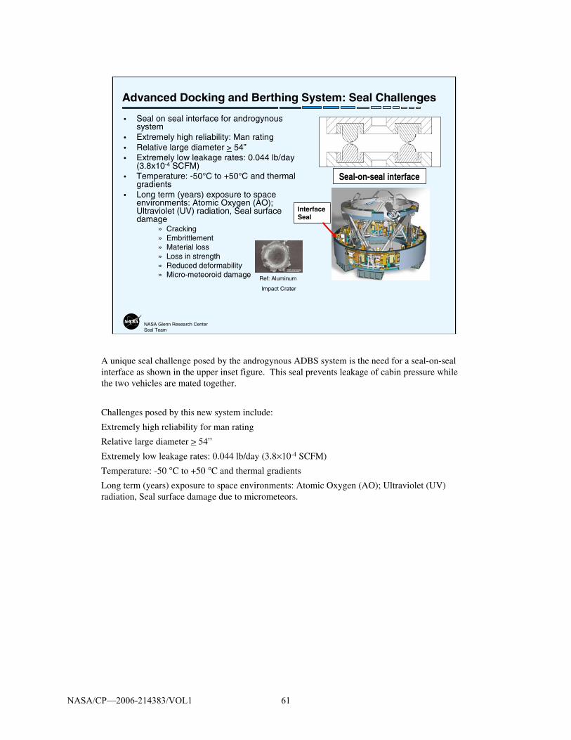
Advanced Docking and Berthing System: Seal Challenges
• Seal on seal interface for androgynous system
• Extremely high reliability: Man rating• Relative large diameter > 54”• Extremely low leakage rates: 0.044 lb/day
(3.8x10⁻⁴ SCFM)• Temperature: -50°C to +50°C and thermal
gradients• Long term (years) exposure to space
environments: Atomic Oxygen (AO); Ultraviolet (UV) radiation, Seal surface damage
» Cracking» Embrittlement» Material loss» Loss in strength» Reduced deformability» Micro-meteoroid damage Ref: Aluminum
Impact Crater
Seal-on-seal interface
Interface Seal
A unique seal challenge posed by the androgynous ADBS system is the need for a seal-on-seal interface as shown in the upper inset figure. This seal prevents leakage of cabin pressure while the two vehicles are mated together.
Challenges posed by this new system include:
Extremely high reliability for man rating
Relative large diameter > 54”
Extremely low leakage rates: 0.044 lb/day (3.8×10⁻⁴ SCFM)
Temperature: -50 °C to +50 °C and thermal gradients
Long term (years) exposure to space environments: Atomic Oxygen (AO); Ultraviolet (UV) radiation, Seal surface damage due to micrometeors.
NASA/CP—2006-214383/VOL1 61

NASA Glenn Research CenterSeal Team
NASA GRC’s Support of ADBS Project
• Goal: Provide JSC with a seal-on-seal system that meets all performance requirements.
• Approach– Identify candidate elastomeric and metallic
seals via NASA and vendor concepts.– Perform coupon-level and small-scale
environmental exposure and flow tests of candidate seals.
– Down-select between competing concepts and materials based on requirements.
– Perform full-scale flow tests (incl. variable gap, offset, hot and cold, seal-on-seal)
» Assess loads: compression, separation
– Support JSC through flight qualification for CEV and other applications
Seal-on-seal interface
Seal Location
NASA Johnson requested the GRC Seal Team to assist in assessing and developing candidate seal technology for the ADBS system, shown in an artist’s rendering of the Crew Exploration Vehicle.
The following elements are planned during the development project:
+ Perform coupon-level and small-scale environmental exposure and flow tests of candidate sub-scale seals
+ Down-select between competing concepts and materials based on requirements
+ Perform full-scale flow tests. Using a new test rig under design, candidate full-scale seals will be subjected to both nominal and off-nominal conditions (e.g. variable gap and offset conditions). The seal’s ability to seal under both warm and cold conditions will also be assessed while tested in a seal-on-seal condition.
+ Assess loads: compression, separation
+ Support JSC through flight qualification for CEV and other applications
NASA/CP—2006-214383/VOL1 62

NASA Glenn Research CenterSeal Team
Astronaut Space Suit & Air lock: Seal Challenges
• Extremely high reliability: Man rated
• Multiple suit locations to enhance astronaut mobility and effectiveness
• Extremely low leakage rates.– Apollo astronaut experience: after first EVA
neck and wrist joint leaks amounted to 0.15 psi/min decay – too high for future missions.
• Long term (years) exposure to space environments: Dust, Ultraviolet (UV) radiation,
» Seal leakage» Seal/joint damage» Dust ingestion:
• Breathing hazard• Shortens mission
During the Apollo program, astronauts found that the suits exhibited several limitations. Dust was able to compromise the seals in the joints causing pressure loss of up to 0.15 psi/minute. This is too high for future Exploration Initiative missions in which astronauts will be expected to perform longer, more frequent missions outside of the landing vehicle.
NASA is now defining programs to develop advanced technologies for future space suits, air locks and quick-disconnect umbilicals. Development of robust seals that overcome the dust issues is essential to meeting future mission requirements.
NASA/CP—2006-214383/VOL1 63

NASA Glenn Research CenterSeal Team
In-Situ Resource Utilization (ISRU) + Seal Challenges
• Benefits of ISRU: In-situ production of mission critical consumables (propellants, life support consumables, and fuel cell reactants) significantly reduces delivered mass to surface.
• Extraction and refinement of nearly any valuable resource from lunar regolith requires thermal and chemical or electrochemical processes in reusable enclosed reactors.
Seal Challenges:• Long term (years) exposure to space
environments: Ultraviolet (UV) radiation, Micrometeroid damage
• Dust: abrasive and electrostatically charged• Temperatures: Cryogenic (propellants) thru
high temperatures for regolith processing• Low leakage rates to maximize product yield• Extremely high reliability
Applications• Resource processing• Mission consumable production
(Life Support & Propellant)• Surface cryogenic fluid &
propellant storage & distribution• Chemical reagent storage &
distribution• Gas storage & distribution• Water & earth storable fluid
storage & distribution
NASA is evaluating In-Situ Resource Utilization (ISRU) technologies that would help allow astronauts to “live-off-the-land.” for either Lunar or Martian missions. These technologies would help increase mission success for a manned mission to Mars that would entail a 6 month transit time and a 500 day stay.
Some of the technologies under consideration, include production of mission critical consumables including:
+ propellants (e.g. harvesting the Martian atmosphere carbon-monoxide to make methane fuel)
+ life support consumables, (e.g. harvesting Lunar ice believed to be at the poles) + fuel cell reactants
Achieving these ambitious goals however requires solving several important seal challenges, as shown in the chart. For additional information about NASA’s ISRU project, please see Sackstedder 2006, in this Workshop Proceedings.
NASA/CP—2006-214383/VOL1 64

Re-Entry and Hypersonic Vehicle: Seal Challenges and Projects Supported
NASA/CP—2006-214383/VOL1 65

NASA Glenn Research CenterSeal Team
NASA GRC Structural Seal Development Goals:
Develop hot (2000-2500+°F), flexible, dynamic structural seals for ram/scramjet propulsion systems (TBCC, RBCC)
Develop reusable re-entry vehicle control surface seals to prevent ingestion of hot (6000 °F) boundary layer flow
Develop TPS and interface system (e.g. landing system) seals for future the Exploration Initiative.
High temperature seals critical for mission success
Ram/Scramjet Engines
ControlSurface Seals
X-37; X-38 CRV
Re-Entry Vehicles
TPS and Interface System seals
NASA is currently funding research on advanced technologies that could greatly increase the reusability, safety, and performance of future hypersonic vehicles. Research work is being performed on both high specific-impulse ram/scramjet engines and advanced re-entry vehicles.
NASA GRC is developing advanced structural seals for both propulsion and vehicle needs by applying advanced design concepts made from emerging high temperature ceramic materials and testing them in advanced test rigs that are under development. See Dunlap 2006, et al, and DeMange 2006, et al in this Seal Workshop Proceedings and Dunlap 2003, et al and DeMange 2003, et al for further details.
NASA/CP—2006-214383/VOL1 66

NASA Glenn Research CenterSeal Team
Seal Challenges and Design Requirements
• Control surface seals:– Limit hot gas flow and heat transfer to underlying low-temperature structures– Withstand temperatures of 1800-2200+F:– Stay resilient for multiple load/heating cycles– Limit loads against sealing surfaces– Resist scrubbing damage
• Propulsion system seals:– Withstand temperatures of 2000-2500+ °F
and high heat fluxes with minimal cooling Limit leakage of hot gases and unburned propellant into backside cavities
– Survive in chemically hostile environment (e.g., oxidation, hydrogen embrittlement)
– Seal distorted sidewalls and remain resilient for multiple heating cycles
– Survive hot scrubbing with acceptable change in flow rates
Permanent set
Baseline control surface seal design
Seals must withstand extreme
heat fluxes
NASA GRC is developing high temperature seals and preloading techniques to help meet the challenges posed by future re-entry and hypersonic vehicle control-surfaces. These seals must limit hot gas ingestion and leakage through sealed gaps to prevent damage of low-temperature structures (including actuators) downstream of the seal. Gas temperatures that reach the seal can be as >2200 °F. The seals must be able to withstand these extreme temperatures and remain resilient, or “springy”, for multiple heating cycles. The upper image on this chart shows what happens to a baseline Shuttle thermal barrier/seal incorporating an knitted Inconcel X750 spring tube after exposure to 1900 °F temperatures in a compressed state. The seals took on a permanent set. This can be a problem if the seal does not stay in contact with the opposing sealing surface and allows hot gases to pass over the seal and into regions where low-temperature materials reside.
Oswald et al 2005, performed finite element analyses on various spring tube designs defining desirable knit parameters to minimize stress while still supporting the necessary loads. Taylor et al 2005, identified the benefits of Rene’41 material over conventional Inconel X-750. Substituting specially heat treated Rene’41 wires raised the operating temperature 250 °F to approximately 1750 °F. The Seal Team is also working on preloading techniques with higher temperature capability and on seal designs that will be more resistant to wear than the conventional seals shown.
Ram/scramjet propulsion system seals must withstand similar punishing temperatures while using minimum cooling. The seals must limit leakage of hot gases and unburned propellant into backside cavities. They must exhibit good resiliency and flexibility to maintain sealing contact with adjacent walls. And must exhibit acceptable change in flow rate with cycling. The seals must meet all of these requirements while resisting the extreme heat fluxes shown in this NASA GRC hydrogen rocket test chamber.
NASA/CP—2006-214383/VOL1 67

NASA Glenn Research CenterSeal Team
FALCON Hypersonic Vehicle Seal Development
• Objective: Develop high temperature seals for control surfaces and access doors on future hypersonic vehicles
• Requirements– Temperature: Extreme– Life: Reusable– Mission duration: Less than 2 hrs
• Approach– Identify and develop high
temperature seals and preload devices
– Perform critical function performance tests at GRC
– Perform arc jet tests on leading concepts at JSC
• Partner organizations: DARPA, Lockheed Martin
Model of GRC seal arc jet test fixture
Falcon vehicle Control surface seals
Leading edge seals
Acreage TPS seals
NASA Glenn is working to develop high temperature seal technology and test techniques for future hypersonic vehicles under DARPA (Defense Advanced Research Project Agency) sponsorship. Vehicle thermal protection system (TPS) seals are required for control surfaces, leading edges and acreage TPS locations. Seals are required to operate under extreme temperatures of hypersonic flight (2000+°F), survive flight times of approximately 2 hrs, and be reusable.
Glenn is developing advanced concepts made of high temperature refractory and ceramic materials, assessing their performance using both GRC’s state-of-the-art high temperature seal test rigs and a new arc jet test fixture. Using this new fixture (being fabricated), control surface seals can be tested under hypersonic heating conditions (Finkbeiner et al 2004). The seals are scrubbed against a ceramic-matrix composite (carbon/silicon carbide) control surface, as the flap is articulated during arc jet exposure simulating flight.
NASA/CP—2006-214383/VOL1 68

NASA Glenn Research CenterSeal Team
Example Structural Seals Being Investigated
Ceramic Wafer Seal• High temperature operation: 2500+˚F• Low Leakage• Flexibility: Relative sliding of adjacent
wafers conforms to wall distortions• Ceramic material lighter weight than
metal system• Tandem seals permit central cavity
purge (cooling)
Braided Rope Seal• High temperature operation: 2400+°F• Flexible: seals & conforms to complex
geometries• Hybrid design (ceramic core/superalloy
wire sheath) resists abrasion• Tandem seals permit central cavity purge
(cooling)
NASA GRC’s work on high temperature structural seal development began in the late 1980’s during the National Aero-Space Plane (NASP) project. GRC led the in-house propulsion system seal development program and oversaw industry efforts for propulsion system and airframe seal development for this vehicle.
Two promising concepts identified during that program included the ceramic wafer seal (Steinetz, 1991) and the braided rope seal (Steinetz and Adams, 1998) shown here. By design, both of these seals are flexible, lightweight, and can operate to very high temperatures. The ceramic wafer seal’s high temperature (2200 °F) performance was demonstrated in GRC’s scrub and flow fixtures (Dunlap et al, 2004). Dunlap et al (2005) investigated wafer size, shape, and dimensional tolerance on seal leakage performance using a design-of-experiments approach. Demange et al (2003) evaluated a variety of braided rope seal configurations with engineered cores to provide greater flexibility than early NASP seal designs.
NASA/CP—2006-214383/VOL1 69

NASA Glenn Research CenterSeal Team
Hot Compression/Scrub Seal Test Rig: Overview
Load frame
Laser extensometer
3000 °F furnace
Seal
Seal holder
Wafer seals
Seal holder
Inconel or Shuttle tile rub surfaces
NASA GRC has installed state-of-the-art test capabilities for evaluating seal performance at temperatures up to 3000 °F (1650 °C). This one-of-a-kind equipment is being used to evaluate existing and new seal designs by simulating the temperatures, loads, and scrubbing conditions that the seals will have to endure during service. The compression test rig (upper left photo) is being used to assess seal load vs. linear compression, preload, & stiffness at temperature. The scrub test rig (middle photo) is being used to assess seal wear rates and frictional loads for various test conditions at temperature. Both sets of fixtures are made of silicon carbide permitting high temperature operation in air.
The test rig includes: an MTS servo-hydraulic load frame, an ATS high temperature air furnace, and a Beta LaserMike non-contact laser extensometer, and the special purpose seal holder hardware. Unique features of the load frame include dual load cells (with multi-ranging capabilities) for accurate measurement of load application, dual servo-valves to permit precise testing at multiple stroke rates (up to 8 in./s.), and a non-contact laser extensometer system to accurately measure displacements.
NASA/CP—2006-214383/VOL1 70

Space Shuttle Main Landing Gear DoorSeal Assessments
NASA/CP—2006-214383/VOL1 71

NASA Glenn Research CenterSeal Team
Shuttle Main Landing Gear Door Seal Tests: STS114
• Issues:– Environmental seals prevented main landing gear (MLG) doors on Discovery from
closing completely: must be fully closed for flight without steps in outer mold line (OML)– Seal performance (leakage, loads) vs. amount of compression not well-characterized
• Objective:– Determine optimal compression on seals to minimize leakage without putting excessive
loads on doors• NASA Johnson Space Center requested testing of MLG environmental seals at
GRC– Room temperature compression tests– Flow tests
Seal cross-sectionSeal
In preparing Shuttle Discovery for the Return-to-Flight mission, engineers at NASA Kennedy Space Center (KSC) and NASA Johnson Space Center (JSC) uncovered a problem in which the environmental seals around the perimeter of the main landing gear doors were preventing the doors from closing completely. This condition is unacceptable for flight because the outer mold line must be smooth during a mission. Raised areas and steps in that surface (such as can be caused by a door that is not fully closed) disrupt the flow of hot reentry gases over the surface and can lead to excessive heating in localized areas.
When this problem was identified, engineers at NASA JSC asked the Seals Team at GRC to help them solve this problem by performing room temperature compression and flow tests on the seals to characterize their performance and determine an optimal compression on the seals to minimize leakage without putting excessive loads on the doors.
NASA/CP—2006-214383/VOL1 72

NASA Glenn Research CenterSeal Team
Shuttle MLG Door Seal Tests – Key Findings
• Loads for seal with excess RTV were more than 2X those for seal with clean bond line.
• GRC also determined preload conditions for acceptable leakage flow.
0
10
20
30
40
50
0 10 20 30 40 50 60 70
% Compression
Lo
ad p
er in
ch o
f se
al (
lbf/
in) RTV Fillet
Clean Bond Line
With RTV fillet
Without RTV fillet
Through discussions with JSC and KSC, it was learned that the RTV used to bond the seals to the MLG doors can often squeeze out under the seal bulb during installation. In these cases the RTV can form a “fillet” below the bulb as opposed to a clean bond line. KSC and JSC thought that this fillet could be playing a role in why the MLG doors would not close.
GRC performed a series of compression tests on both bulb configurations and discovered that peak loads for seals with an RTV fillet below their bulbs were more than twice as high as those for seals with a clean bond line. Finkbeiner et al, 2005 documents the results of these studies.
NASA/CP—2006-214383/VOL1 73
NASA Glenn Research CenterSeal Team
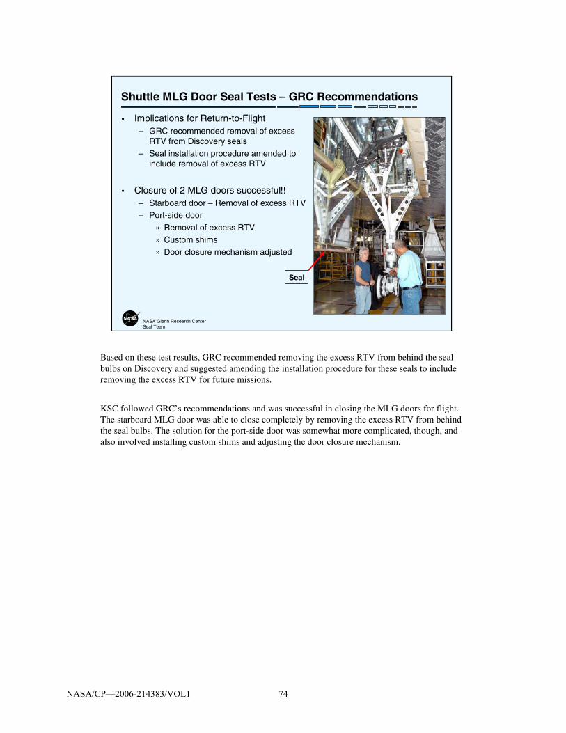
Shuttle MLG Door Seal Tests – GRC Recommendations
• Implications for Return-to-Flight– GRC recommended removal of excess
RTV from Discovery seals
– Seal installation procedure amended to include removal of excess RTV
• Closure of 2 MLG doors successful!!– Starboard door – Removal of excess RTV
– Port-side door
» Removal of excess RTV
» Custom shims
» Door closure mechanism adjusted
Seal
Based on these test results, GRC recommended removing the excess RTV from behind the seal bulbs on Discovery and suggested amending the installation procedure for these seals to include removing the excess RTV for future missions.
KSC followed GRC’s recommendations and was successful in closing the MLG doors for flight. The starboard MLG door was able to close completely by removing the excess RTV from behind the seal bulbs. The solution for the port-side door was somewhat more complicated, though, and also involved installing custom shims and adjusting the door closure mechanism.
NASA/CP—2006-214383/VOL1 74

NASA Glenn Research CenterSeal Team
• Seals technology recognized as critical in meeting next generation aero-and space propulsion, power and space vehicle system goals
• Performance • Efficiency • Life/Reusability• Safety• Cost
• NASA Glenn’s RolePartnered with key government and contractor organizations to
• Develop advanced seal technology • Provide technical consultation
for the Nation’s key aero- and space advanced technology development programs.
Summary
NASA Glenn is currently performing seal research supporting both advanced turbine engine development and advanced space vehicle/propulsion system development. Studies have shown that decreasing parasitic leakage through applying advanced seals will increase turbine engine performance and decrease operating costs.
Studies have also shown that higher temperature, long life seals are critical in meeting next generation space vehicle and propulsion system goals in the areas of performance, reusability, safety, and cost.
NASA Glenn is developing seal technology and providing technical consultation for the Agency’s key aero- and space technology development programs.
NASA/CP—2006-214383/VOL1 75

NASA Glenn Research CenterSeal Team
NASA Seals Web Sites
• Turbine Seal Development– http:/www.grc.nasa.gov/WWW/TurbineSeal/TurbineSeal.html
» NASA Technical Papers
» Workshop Proceedings
• Structural Seal Development– http://www/grc.nasa.gov/WWW/structuralseal/
» NASA Technical Papers
» Discussion
» Seal Patents
– http://www/lerc.nasa.gov/WWW/TU/InventYr/1996Inv_Yr.htm
The Seal Team maintains three web pages to disseminate publicly available information in the areas of turbine engine and structural seal development. Please visit these web sites to obtain past workshop proceedings and copies of NASA technical papers and patents.
NASA/CP—2006-214383/VOL1 76

NASA Glenn Research CenterSeal Team
References
• Braun, M.J., Choy, F.K., Pierson, H.M., 2003, “Structural and Dynamic Considerations Towards the Design of Padded Finger Seals”, AIAA-2003-4698 presented at the AIAA/ASME/SAE/ASEE conference, July, Huntsville, AL.
• DeMange, J.J., Dunlap, P.H., Steinetz, B.M., 2003,“Advanced Control Surface Seal Development for Future Space Vehicles,” Presentation and Paper at 2003 JANNAF Conference, Dec. 1-5, Colorado Springs, CO. (NASA TM in progress).
• Dunlap, Jr., P.H., Finkbeiner, J.R., Steinetz, B.M., DeMange, J.J., 2005," Design Study of Wafer Seals for Future Hypersonic Vehicles,” AIAA-2005-4153, presented at the 41st AIAA/ASME/SAE/ASEE Joint Propulsion Conference, Tucson, AZ, July 10-13.
• Dunlap, P.H., Steinetz, B.M., and DeMange, J.J.: 2004, "Further Investigations of Hypersonic Engine Seals." NASA TM-2004-213188, AIAA-2004-3887, August 2004. Presented at the 2004 AIAA/ASME/SAE/ASEE Joint Propulsion Conference, July, Ft. Lauderdale, FL.
• Dunlap, P.H., Steinetz, B.M., DeMange, J.J., 2003, “High Temperature Propulsion System Structural Seals for Future Space Launch Vehicles,” Presentation and Paper at 2003 JANNAF Conference, Dec. 1-5, Colorado Springs, CO. (NASA TM-2004-212907).
• Finkbeiner, J.R., Dunlap, Jr., P.H., DeMange, J.J., Steinetz, B.M., 2005, "Investigations of Shuttle Main Landing Gear Door Environmental Seals," AIAA-2005-4155, presented at the 41st AIAA/ASME/SAE/ASEE Joint Propulsion Conference, Tucson, AZ, July 10-13.
• Finkbeiner, J.R., Dunlap, P.H., Steinetz, B.M., Robbie, M., Baker, F., and Erker, A., 2004, “On the Development of a Unique Arc Jet Test Apparatus for Control Surface Seal Evaluations.” NASA TM-2004-213204, AIAA-2004-3891, August 2004. Presented at the 2004 AIAA/ASME/SAE/ASEE Joint Propulsion Conference, July, Ft. Lauderdale, FL.
• General Electric Aircraft Engines, 2004, “HPT Clearance Control (Intelligent Engine Systems)—Phase I—Final Report” NASA Contract NAS3–01135, April.
• Lattime, S.B., Steinetz, Bruce M., Robbie, M., 2003, “Test Rig for Evaluating Active Turbine Blade Tip Clearance Control Concepts,” NASA TM-2003-212533, also AIAA-2003-4700, presented at the AIAA/ASME/SAE/ASEE conference, July, Huntsville, AL.
• Lattime, S.B., Steinetz, B.M. 2002 “Turbine Engine Clearance Control Systems: Current Practices and Future Directions, “ NASA TM-2002-211794, AIAA 2002-3790.
• Oswald, J. J., Mullen, R.L., Dunlap, Jr., P.H., Steinetz, B. M., 2005, “Modeling on Canted coil Springs and Knitted Spring Tubes as High Temperature Seal Preload Devices,” AIAA-2005-4156, presented at the 41st AIAA/ASME/SAE/ASEE Joint Propulsion Conference, Tucson, AZ, July 10-13.
NASA/CP—2006-214383/VOL1 77
NASA Glenn Research CenterSeal Team
References (Cont’d)• Proctor, M.P; Kumar, A.; Delgado, I.R.; 2002, “High-Speed, High Temperature, Finger Seal Test Results,” NASA TM-
2002-211589, AIAA-2002-3793.• Proctor, M.P., Steinetz, B.M. Non Contacting Finger Seal, U.S. Patent 6,811,154, Issued 11/02/04, (LEW 17,129-1).• Steinetz, B.M., Lattime, S.B., Taylor, S., DeCastro, J.A., Oswald, J., Melcher, K.A., 2005, “Evaluation of an Active Clearance
Control System Concept,” NASA TM-2005-213856, AIAA-2005-3989. Presented at the 2005 AIAA/ASME/SAE/ASEE Joint Propulsion Conference, Tucson, AZ.
• Steinetz, B.M., Hendricks, R.C., and Munson, J.H., 1998, “Advanced Seal Technology Role in Meeting Next Generation Turbine Engine Goals,” NASA TM-1998-206961.
• Steinetz, Bruce M.; Adams, Michael L.: 1998, “Effects of Compression, Staging and Braid Angle on Braided Rope Seal Performance”, J. of Propulsion and Power, Vol. 14, No. 6, also AIAA-97-2872, 1997 AIAA Joint Propulsion Conference, Seattle, Washington, July 7-9, 1997, NASA TM-107504, July 1997.
• Steinetz, B.M.: 1991, “High Temperature Performance Evaluation of a Hypersonic Engine Ceramic Wafer Seal,” NASA TM-103737.
• Taylor, S.C., DeMange, J.J., Dunlap, Jr., P.H., Steinetz, B.M., 2005, "Further Investigations of High Temperature Knitted Spring Tubes for Advanced Control Surface Seal Applications," AIAA-2005-4154, presented at the 41st AIAA/ASME/SAE/ASEE Joint Propulsion Conference, Tucson, AZ, July 10-13.
• Wiseman, M.W., Guo, T.,2001,“An Investigation of Life Extending Control Techniques for Gas Turbine Engines,” Proceedings of the American Control Conference, IEEE Service Center, Piscataway, NJ, IEEE Catalog No. 01CH37148, vol. 5, pp. 3706–3707.
NASA/CP—2006-214383/VOL1 78