overview of nmc to ibm host setup of nmc to ibm host setup introduction.. 2 overview of sna...
TRANSCRIPT

/
Overview of NMC to IBM host setupINTRODUCTION.. 2
OVERVIEW OF SNA ARCmTECTURE 2
NODETYPESANDLV TYPESTIlEYSUPPORT: 4SNA STACKOUlLINE 5SUMMARYOFCOMMUNICATIONSINSNA NETWORKANDLV6.2 PROTOCOL 8
DECNET OVERVIEW 9
DEC SNA PRODUCT ARCHITECTURE. 9
NMC CONNECTIONS TO THE SNA WORLD 11
NMC CONNECTIONTOTYPE5.0 NODES(370,43xx COMPUTERS) 11NMC CONNECTIONTOTYPE2.1 NODES(AS/400 COMPUTERS) 13NOTEONTHEDIRECTINTERFACETOETIlERNETDEVICEDRIVERS 13A NOTEABOUTFORESTCOMPUTER5740 14
Author: Nasser AbbasiDate: 06/28/95
--- ---

NMC/CI link to PU5.0 and PU2.1 ffiM nodes
IntroductionThe objective of this report is to give a general outline of SNA in the hope this might help betterunderstand the way the NMC communicates with ffiM customer computers (both ffiM mainframe andffiM midrange computers).
Overview of SNA architectureAn SNA network consists of SUBAREA's connected to each other via a communication link:
Subarea 1 Subarea2
Communication link
There are 2 kinds of subareas: A Host subarea and a communication controller subarea.
A Subarea contain in it a subarea nodes and peripheral nodes. There are 2 types of subarea nodes: A Hostsubarea node and a Communication controller subarea node. A peripheral nodes include clustercontrollers, workstations, printers and so on. A subarea can not contain 2 different kinds of Subareanodes, it is either is a Host subarea node or a communication controller subarea node, but a subarea cancontain a subarea node and a peripheral node. The following diagram shows a typical SNA network:
A Host subarea node that contain a Physical Unit of type 5.0 ( PU5.0) together with a software calledSSCP (system service control point) are refereed to as type 5.0 node. the SSCP software manages theactivation or termination of sessions between different SNA connections and manages network resourcesand can only reside on a Host subarea node.
2
SubArea 1
Channell Attached
I HOST subarea node I I Peripheral node I
Data Channel
SubArea 2
I Communication controller Subarea node ISDLC Unk I
Peripheralnode I

NMC/CI link to PU5.0 and PU2.1 ffiM nodes
A communication controller subarea node that contains a PU4.0 device is called a type 4.0 node.
A peripheral node that contains a PU2.0 device is called type 2.0 node.
A peripheral node that contains a PU2.1 device together with its own SSCP software is called type 2.1node.
PU5.0 is products such as ACFNTAM, 4300, 308x, 9370, 3090.
PU4.0 is products such as NCP, 3720,3705,3725,3745.
PU2.1 is products such as system/36,system/38,ffiMIPC,TPF,AS/400.
PU2.0 is products such as 3174,3274,3276,ffiMIPC,3770..
There is also a PU1.0 for products such as 3271,6670,3767.
Node type 2.1 together with LU6.2 are the main components of ffiM new network architecture calledAPPN (advanced program to program Network).
So a typical SNA network drawn in terms of node types would look like this:
Type 5.0node 8
[ SSCP ]
SDLC type 2.0 node
Type 4.0 node
DLC
type 2.1 node PU2.1
SSCP
Communications in SNA network occurs between what is called NAU's (Network Addressable Units).
3
-- -

NMC/CI link to PU5.0 and PU2.I ffiM nodes
SNA recognizes three types ofNAU's:
. Logical Unit (LU). An LU can be looked at as the port to the network through which an end user(such as a program) can enter the network. SNA only sees the LU, any end user can use the LUto communicate with another end user on a different LU. (Think of an LU as sort of a socket ifyou well, but they are not the same).
. Physical Units (PU).
. SSCP (System Service Control point).
Different Physical units (PU) support different LU types. There are 8 LU types (classified in terms of thecapability they provide to the end user). More powerful node types (such as 5.0 and 4.0) support moretypes of LU's.
Node types and LUtypes they support:1. Type 2.0: supports LU2,LU3,LU6.2,LUI
2. Type 2.1: supports LUI ,LU2,LU3,LU6.2 and direct link connection to other 2.1 nodes.
3. type 4.0: no support for LU NAU's. type 4.0 nodes perform routing and control of flow.
4. type 5.0: support all LU's.
The following diagram shows a typical SNA network showing how the LU fits in the overall picture:
Subarea 1
Type 5.0 node
PU5.0
SSCP
subarea 2session conversation
peripheral node
Type 4.0 node
8SDLC
In the above diagram, the LU residing in the peripheral node is called the secondary LU, and the LUresiding in the type 5.0 node is called the primary LU. The diagram shows that LU's residing on type 2.0units can only communicate with LU's residing on type 5.0 node.
type 2.1 nodes were created by ffiM to allow end users on peripheral nodes to communicate with other endusers on other peripheral nodes without the need to have a PU5.0 nodes in the network.The following diagram shows how this is done (this is a typical SNA network for APPN layout).
4
--- - -

. ....---
NMC/CI link to PU5.0 and PU2.1 ffiM nodes
end user program
end user program
SNA stack outline
The SNA stack can be looked at as broken into 2 functional groups, the Network Addressable Unit and thePath Control network function, as shown in this picture:
"-
"-
"-
"-
//
//'-.'-.'-.'-../
././
./
Network Addressable Unit and Boundary Function
Path Control Network Function
Functions of each layer in the stack:Phvsicallaver: Physical medium over which signal travel.Data link laver: Implements the protocol to insure accurate and orderly exchange of information between2 or more DTE's (Data Terminal Equipment). The type of devices that use the physical line dictate thelink protocol to use, so there is hardware dependencies of a device for a specific data link protocol. Thereare 2 main categories of link protocols, non-SNA link protocols and SNA link protocols.Non-SNA link protocols are:1. SIS (Start/Stop Asynchronous protocol), used for ffiM 3767, IBM 3101, WTTY type device. SIS link
protocol is not supported by VTAM.2. BSC (Binary Synchronous Communication) which is older and being rapidly replaced by SDLC
(Synchronous Data Link Control).3. X.25. This allows the application to transmit data over public telephone circuits, data is broken up in
packets, X.25 headers added and the packet send over the public telephone network. (DECnet alsosupports X.25 data link protocols).
SNA main link protocol is the SDLC. This is more efficient for data transmission and recovery. SDLCframe is shown later on.Path Control Laver:Selects the next link on the path towards the destination. Routing decision is madehere.
5
- - - -
Transaction Services Layer
Presentation services layer
Data Flow Control Layer
Transmission Control Layer
Path Control Layer
Data Unk Control Layer
Physical Control Layer

NMC/CI link to PU5.0 and PU2.1 IBM nodes
Transmission control laver: This layer is responsible for maintaining the session. Routes message frompath control to the correct destination inside the data flow control layer. This layer also builds the RHbefore sending the message to the path control layer.Data flow control laver: Concerned with management of message protocol. Such as correlating responseswith requests, managing sequence numbers, controlling which side can send and when, to do this the dataflow control layer sends data flow control messages to the other data flow control layer in the othercomputer.Presentation services layer: Interpretation of data to the user is done here, for example the DECimplementation of APPC/LU6.2 (the product than runs on VMS) will perform EBCDIC to ASCII and viseversa translation at this level when communicating with IBM computers.Transaction services laver: The end user applications CICS transactions or VAX/YMS applications.
As we will see below, The DEC APPC/LU6.2 Software that runs on the VAX implements the NAU andBoundary Function part(Presentation, Data Flow Control, Transmission Flow Control) , while the DECSNA GATEWAY implements the path control network functions. This is because each LU type will havedifferent implementation of the NAU/Boundary function layer, while the common software (the PathControl Network function) is shared among all LU types and resides on the SNA GATEWAY.
The following diagram shows the SNA message unit structure at each layer of the SNA stack:
6

NMC/CI link to PU5.0 and PU2.1 ffiM nodes
ReqlResponse
Unit (RU)
End User Data or
SNA command Data
RrquesVResponse unit (RU)- - - - - - - - - - --- - - -- - -- - --- - -- - - - - - - - - - - - - - - - - - - - - - - - - -----
\\\\
)/
//
/
Pefromed by LU software
(example, on VAX performed
By APPCILU6.2 access routine
Basic Information Unit (BIU)
- - - - -- - - --- - - - - - - - - - - -- - - - - ------
FIDtypel OAFIDA
Req/Response
ReqlRespseHeader (RH) Unit (RU)
DR CDI
ER EDI
PI CEBI
nd User Data or
Transmission Header (TH)
NA command Data
-------------------- - - - - - - - - - - - - - - - - - - - - - - - - - -
Basic Link Unit (BLU)- - - - - - - - - - - - - --- - -- - - -- - - - - - - - - - - - -- - - - - - - - - - -- -- - ---
The SDLC frame size breaks down like this:
8 bits 8 bits 8 bits variable 16 bits 8 bits
7
ransaction
=>resentation
service
Layer
Data Flow
Control
Layer
ransmission
Control
Layer
Path
Control
Layer
Data Unk
Control
Layer
PhysicalControl
Layer
ReqlResponse
ReqlRespseHeader (RH) Unit (RU)
RH Type OF! CDI
DataType ER EDInd User Data or
SOl BCI PI CEBI SNAcommand DataECI
(LH) HeqtHesponseink Trailer (LT)SDLC Unk Header TransmissionHeader (TH) Req/RespseHeader (RH) Unit (RU)
Flag Station :Ontrc FID type OAF OAF Sequence RH Type DR CDI FramAddress Field number DataType ER EDI
nd User Data or Chec lag
SOl BCI PI CEBI SNAcommand Data SequenceECI
Flag station address Control field Variable length information rame check lag
(Path Information Unit)

NMC/CI link to PU5.0 and PU2.1 ffiM nodes
Acronvms descriotion:the flag in the LH always has value of HEX 7E, this indicates the start of a new SDLC frame.Station address: For broadcast message (all stations) SDLC uses HEX FF. for no station, it uses 00, else aspecific station address is used.FID: Format Identification Field, this field specifies the type of PU, depending of the PU type, the THlength can vary in size from 10 bytes to 26 bytes. So the TH header has 5 different formats depending onthe FID value.OAF: Originating address field.OAF: Destination address field.SOl: Sense Data Indicator.BCI: Begin Chain Indicator.COI: Change Direction Indicator.CEBI: Conditional End Bracket Indicator.OR: Definite Request/Response Indicator.ECI: End Chain Indicator.
EDI: Enciphered Data Indicator.ER: Exception Request/Response Indicator.PI: Pacing Indicator. Pacing is the ffiM SNA method of flow control; it allows the network to regulatebuffer usage per individual session.
Summary of communications in SNAnetwork and LU6.2protocolSNA is considered a hierarchical (or star) type of network (peripheral nodes connect to a controller whichconnects to a host node). With the addition of PU2.1 type node that allows peer to peer communications(since a host is not needed any more), ffiM is moving SNA to become a peer-to-peer type of network (lesscentralized). LU6.2 and PU2.1 nodes are the main components for this new SNA architecture calledAPPN.
Communications in SNA between end user is accomplished via LU's. A session is started between 2 LU'swith the help of SSCP. An LU resides in an SNA node. different SNA nodes can support different LUcapabilities. LU6.2 is the most flexible LU type. Traffic flows between 2 LU6.2 type LU's over a session.
Communication between 2 end users who are using LU6.2 type of LU requires first the establishment of asession, once a session is created between the 2 LU's, then traffic can start. Data flow in an LU6.2 sessiononce a conversation is started. A conversation can start and finish while the session remain for futurereuse. Many conversation can occur over one session. LU6.2 data flow is full-duplex type of protocol,Traffic can flow in either direction over the same session during a conversation.
The following diagram shows an LU6.2 conversation in progress:
SESSION
8

NMC/CI link to PU5.0 and PU2.1 IBM nodes
DECnet OverviewDECnet is a symmetric peer-to-peer based architecture, i.e. nodes in DECnet can communicate with othernodes without having to go though a centralized node (such as with SNA). each node in DECnet has itsown unique DECnet address that is made of an area address and node address within that area. nodes inthe network are connected by lines over which circuits operate, see below:
! NODE]
logical linkNODE
process
..circuit_
Une
A line is the physical connection between 2 nodes (can be Ethernet, FDDI, microwave, etcoo).A circuit isthe logical connection between the nodes, it is the logical data path over which traffic travel between thenodes. I/O between nodes occur over circuits.
A logical link is a link between 2 processes running over 2 DECnet nodes. A logical link connects 2processes for the purpose of exchanging data. (a logical link can be established between 2 processes overthe same node as well.)
DEC SNA product architectureI outline briefly DEC SNA architecture as that will help show how the SNA gateway fit in the big picture.
DEC SNA architecture is made up of 5 layers. The layers are:
These five layers are not all implemented in the same node as the end user. DEC defines 2 distinctdistributions, one is called the gateway access model (which is how NMC connects to the SNNGateway)and the other called the server mode. In the gateway access model, the Functional and SNA interfacelayers are located in the same node as the user, while the other 3 layers are located in the gateway node.The interface between the SNA interface layer and the common network layer in this case is DECproprietary protocol and is called GAP ( gateway access protocol).
9
. Functional layer. SNA interface layer. Common network layer
. Data link layer. Physical layer

NMC/CI link to PU5.0 and PU2.1 ffiM nodes
In the Server model, all 5 layers are located in the gateway, and the user access the gateway using many ofthe already available methods, for example DECnet task-to-task.
The following diagram outlines DEC SNA product architecture
user programI 3270terminalemulator FUNCTIONAL LAYER
SNA INTERFACE LAYER
Execute on VMS
In Gateway Access Model
Standard Common Net Interface
GatewayAccess Server (GAS)
COMMON NETWORK LAYER
Common Sessin control and Path Control
Standard data link interface Execute on Gateway
DATA LINK LAYER
SDLC I X.25 I etc..
Standard Driver InterfacePhysical Layer
RS232 I V.35 I X.21
To SNA Network (3725 front end)
The GAS component above supports GAP. GAS receives messages from SNA network session and sendsthem to the correct DECnet logical link. It also does the reverse, takes messages from DECnet logicallinks and send them to the correct ffiM SNA session. GAS keeps the correlation between an SNA sessionand a DECnet logical link, this correlation starts at connection time.
It is important to note that connection to the ffiM applications always initiated from the DECnet side (Idon't know if DEC has any new products that would allow ffiM applications to start the connection toVAXlVMS applications).
10

NMC/CI link to PU5.0 and PU2.1 mM nodes
NMC connections to the SNA worldSince NMC runs on DEC computers and the customer dispatch software runs on mM computers, NMCuses the following 2 methods to connect to the customer computers depending on if the customer uses type5.0 nodes or type 2.1 nodes.1. NMC connects to mM host (PU5.0) using DEC SNA gateway (PU2.0) using LU6.2 LU type.2. NMC connects to mM midrange computer (AS/400) using PC SNA gateway (PU2.1) over Ethernet
link.
The following describes in more details each connection.
NMC connection to type 5.0 nodes (370,43xx computers)NMC usesDECSNAgateway-STto communicatewithPU5.0mM host.NMCsoftwarecomponent(SNA_CI) program communicate with the CICS transaction running on the host over LU6.2 LU types.The DEC SNA gateway looks like a DECnet node to VAX running the NMC software, while it looks likea PU2.0 to the SSCP software running on the mM host.
The following diagram shows how the messages flow between the user program (on VMS) and thegateway in a typical communication session with mM computer. This diagram show how a connection isstarted, it shows the BIND arriving from mM (BIND is the data that the mM LU uses to specify the typeof session characteristics it will be using during this session such as max. buffer size for messages overthis session), then it shows the data is exchanged between the 2 LU's and then an UNBIND arrives to endthe session. Time flows from top to bottom. i.e. the activities at the top of the diagram happen before theactivities at the bottom of the diagram.
NTROL-INIT
_ ProgramLU
GAP protocl message -. SNA session protocol PLU
Gateway.
VAXNMS IBM computer
11
connect "-7 INIT-SELF
SSCP.......-
I
/ BIND-data
BIND J/ cor
L
BIND-accepted
Data
Data
Data
Data
-7
L1UNBIND
ABORT- .-
NMC/CI link to PU5.0 and PU2.1 ffiM nodes
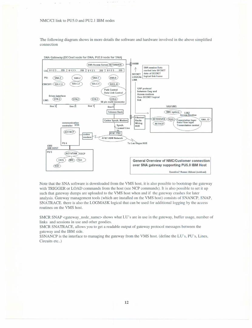
The following diagram shows in more details the software and hardware involved in the above simplifiedconnection
SNA Gateway (DECnet node for DNA. PU2.0 node for SNA)
(SMAAccessServe~~
Lu:1 0123...255 II0123...255 II0123...255 II0123...255 I
~~~c§:> ~ GD~D
H4oo0
pU: 0~RClIIT:~D~C3:)
tI
SMAsession Datacarried Inlo DECNEr
DECNEr data of DECNErLOGICAL logical link frameLINK
Dr~aceLINE: ~
GAP prolocolbetween Gwy andAccess routinesOver DECNEr logicallink
000.!!!!!.!!OSTPU5
~ CsYiW50 pin m~nector
line 1
communicationcontroller 3725
as HUB
General Overview of NMC/Customer connection
over SNA gateway supporting PU5.0 IBM Host
Questins7 Nasser Abbasi (nabbaSl'
Note that the SNA software is downloaded from the VMS host, it is also possible to bootstrap the gatewaywith TRIGGER or LOAD commands from the host (see NCP commands). It is also possible to set it upsuch that gateway dumps are uploaded to the VMS host when and if the gateway crashes for lateranalysis. Gateway management tools (which are installed on the VMS host) consists of SNANCP, SNAP,SNAmACE. there is also the LOGMASK logical that can be used for additional logging by the accessroutines on the VMS host.
$MCR SNAP <gateway_node_name> shows what LU's are in use in the gateway, buffer usage, number oflinks and sessions in use and other goodies.$MCR SNAmACE, allows you to get a readable output of gateway protocol messages between thegateway and the ffiM side.$SNANCP is the interface to managing the gateway from the VMS host. (define the LU's, PU's, Lines,Circuits etc..)
12

NMC/CI link to PU5.0 and PU2.1 IBM nodes
NMCconnection to type 2.1 nodes (AS/400 computers)NMC uses PC SNA gateway to communicate with PU2.1 IBM AS/400.The PC SNA gateway looks like a PU2.1 to the SSCP software running on the AS/400.
NMC CI program uses ECIR.EXE to communicate over ethemet to the PC SNA gateway. ECIR.EXE uses$QIO to interface with the ethemet driver. ECIR.EXE read the fileOMNCCONFIG:ECIR_CONFIG.DAT to find out the ethemet device name to obtain a channel on thelocal node, then once a channel is assigned, ECIR.EXE uses $QIO to send write and read ethemet packetsfrom that channel on the ethemet device, ECIR.EXE send ethemet packets received from the remotePC/SNA gateway to the correct CI program based on the CI ID number (via VMS mailbox).
Note on the Direct Interface to Ethernet device drivers
VMS comes with a number of I/O drivers. $QIO system service calls are used to interface to the driversthough the use of the PI though P6 paramters on the $QIO calls).
The NMC connection to the PC SNA gateway is done by direct ethemet I/O over ethemet using the VMSethemet driver. The format of ethemet packet is like this:
6 bytes 6 bytes 2 bytes 2 bytes variable variable 4 bytes
Destinatinethemet address I SourceEthernetaddess I protocoltype ID I Lengthof user data
the minimum size of ethemet packet must be 64 bytes, padding is used to make the header, data and CRC64 bytes if needed.
For the purpose of this discussion that is all we need to know about DECnet. (actually that is about all Iknow about DECnet stuff).
13

NMC/CI link to PU5.0 and PU2.1 ffiM nodes
The following diagram shows in more details the software and hardware involved in this connection
PU2.1Ethernet
IIII Ethernet traffic NMC software
PC SNA Gateway
VAXNMS
AS/400IBMcomputer I PU2.1
A note about Forest Computer 5740I did some looking around to find a way to replace the many PC SNA boxes that we have with just onebox that will allow the CI's to talk to ffiM midrange computers, with the goal of having a better way,easier to maintain method, of establishing this link without using the many PC SNA boxes. Found acompany in Michigan called Forest Computer, (Please see attached information sheets they faxed me) thatbuilds a box that allows VMS based applications to connect to ffiM midrange computers (AS/400).
The VMS applications (in our case the CI's) communicate with this box using DECnet task-to-taskcommunication (a server on the 5740 box is a DECnet object). The box in turn communicates with ffiMmidrange computers using APPC/LU6.2 protocol over SDLC line.
Either side can start the conversation, multiple clients can talk to the same server (on the 5740).
Since the 5740 box uses DECnet task-to-task to talk to the VAX side, there would have to be code written(new CI interface) to communicate with this box. More information is needed to investigate this more.
Talking to their sale person, he mentioned that pricing starts about $30,000 per box, for about 12 sessionsper box. support for 36 concurrent sessions is more $$.
The sale person I talked to is Russ Ferance at 517-349-4700.
14