overview of process intensification - costello of process intensification october 19, 2010 rocky c....
TRANSCRIPT

This area to be used for Company Logo First slide only
© 2010 R.C. Costello & Assoc., Inc.
Overview of Process Intensification
October 19, 2010Rocky C. Costello, P.E.
http://www.rccostello.con310-792-5870
COSTELLO

2
What is Process Intensification (PI)?
Technologies and Strategies that reduce the physical size of operating
units thereby enabling cost reductions
(capital, operating, maintenance)
© 2010 R.C. Costello & Assoc., Inc.

3
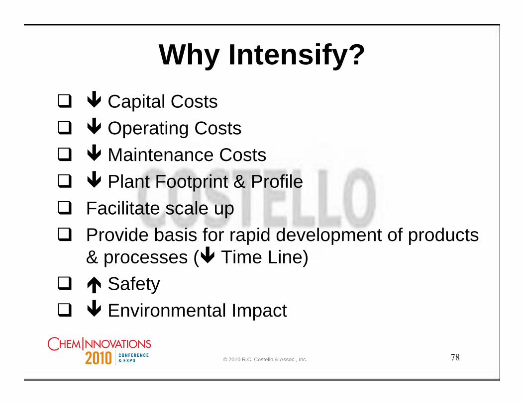
Why Intensify?Capital CostsOperating CostsMaintenance CostsPlant Footprint & Profile
Facilitate scale upProvide basis for rapid development of products & processes ( Time Line)
SafetyEnvironmental Impact
© 2010 R.C. Costello & Assoc., Inc.
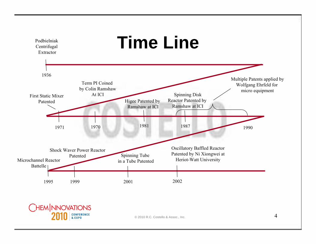
4
Time LinePodbielniakCentrifugal
Extractor
1936
1970
Term PI Coined by Colin Ramshaw
At ICI
1981
Higee Patented by Ramshaw at ICI
1987
Spinning DiskReactor Patented by
Ramshaw at ICI
2001
Spinning Tube in a Tube Patented
1999
Shock Waver Power ReactorPatented
1990
Multiple Patents applied byWolfgang Ehrfeld for
micro equipment
Oscillatory Baffled ReactorPatented by Ni Xiongwei at
Heriot-Watt University
2002
1971
First Static MixerPatented
1995
Microchannel ReactorBattelle
© 2010 R.C. Costello & Assoc., Inc.
5
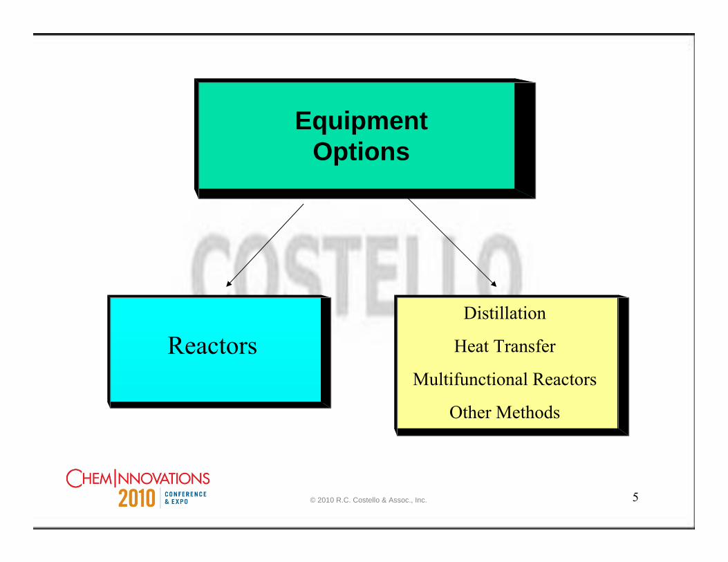
Equipment Options
ReactorsDistillation
Heat Transfer
Multifunctional Reactors
Other Methods
© 2010 R.C. Costello & Assoc., Inc.
6
Reactors
© 2010 R.C. Costello & Assoc., Inc.
7
Traditionally, How Were Reactors Selected?
“Sometimes the choice of equipment was due to expediency and was jelled by tradition; or it may have been an inventor’s individual preference, uninhibited by much knowledge of scientific principles.”
Source: Reaction Kinetics for Chemical Engineers, Chapter 10, Industrial Reactors, By Stanley M. Walas
© 2010 R.C. Costello & Assoc., Inc.
8
Today’s Reactor Choice?
Situation Driven (The Chemistry)
Need Selected(Improve product quality)(Reduce installed cost)(Reduce purification steps)
© 2010 R.C. Costello & Assoc., Inc.

9
Reactors Classified by Size
• Micro - Millimeters
• Meso - Centimeters
• Macro - Meters
Focus - reactors with moving parts
© 2010 R.C. Costello & Assoc., Inc.

10
Micro Reactors• Used in laboratories with most being little stirred tank units
• Can be set up in arrays with 100 reactors operating in parallel to test 10 different temperatures on one side of the array versus 10 different molar ratios on the other side of the array for reaction optimization
• May or may not scale up
© 2010 R.C. Costello & Assoc., Inc.

11
Meso Reactors
• The most commonly used size
• Typically scalable with in the meso scale range
• Wide range of options
© 2010 R.C. Costello & Assoc., Inc.

12
Macro Reactors
•None operational to my knowledge
© 2010 R.C. Costello & Assoc., Inc.

13
Ehrfeld Modular MicroReaction System
© 2010 R.C. Costello & Assoc., Inc.

14
Ehrfeld Modular MicroReactionSystem
•More than 40 different modules•Flexible assembly concept•Easy process control & automation•Easy Scale-up•Pressure 0 to 100 bar (other ranges on request)•Temperature -100 to 200 °C (others ranges on request)•Materials
•Stainless Steel 304L & 316L•Hastelloy C-276•Glass•other materials on request
© 2010 R.C. Costello & Assoc., Inc.

15
Typical Modules Include:
•Mixers•Heat Exchangers•Reactors•Filters•Sensors
Ehrfeld Modular MicroReactionSystem
© 2010 R.C. Costello & Assoc., Inc.

16
Kreido STT™
© 2010 R.C. Costello & Assoc., Inc.
17
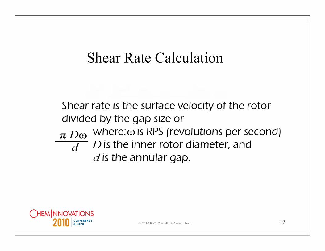
Shear Rate Calculation
© 2010 R.C. Costello & Assoc., Inc.

18© 2010 R.C. Costello & Assoc., Inc.
19
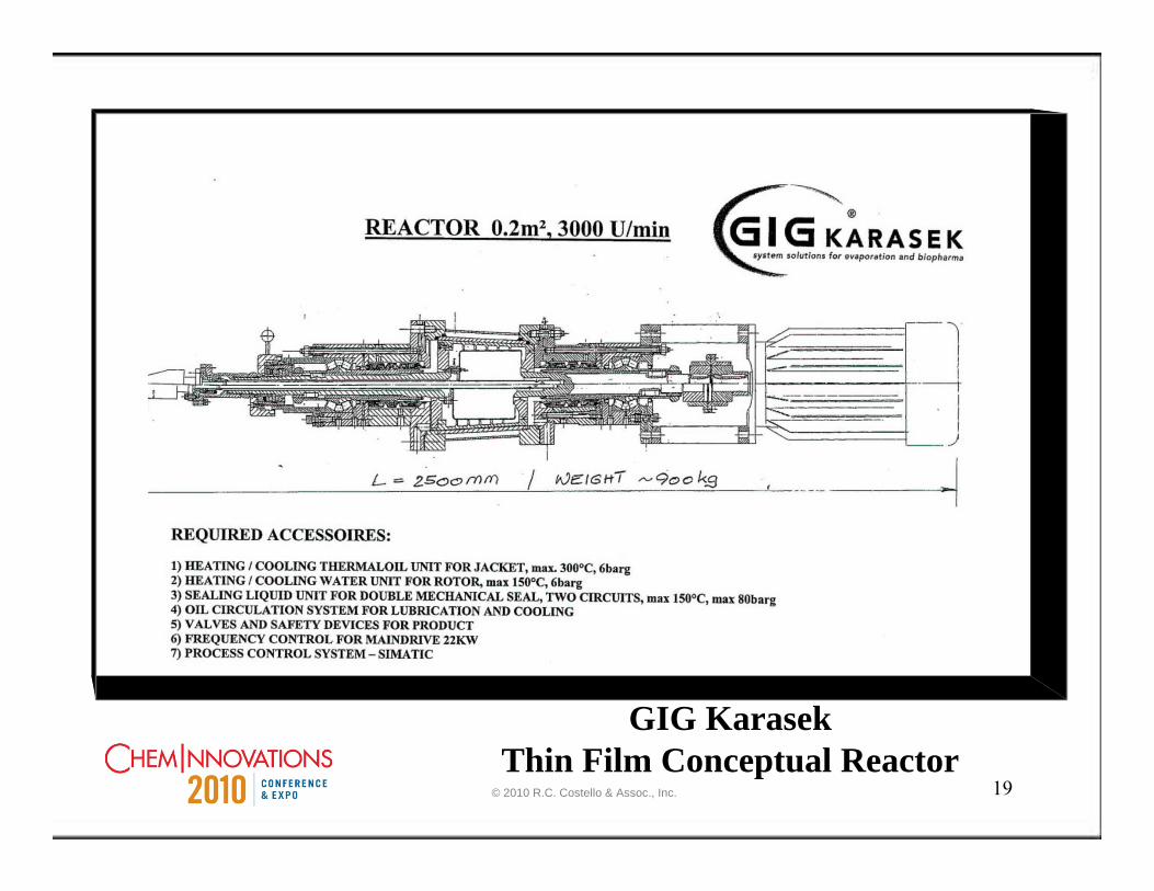
GIG KarasekThin Film Conceptual Reactor
© 2010 R.C. Costello & Assoc., Inc.

20
Features of the GIG KaraseckConceptual Thin Film Reactor
Variable speedVariable gapCooling on the rotorCooling on the statorMechanical SealsExperience with thin film evaporators
© 2010 R.C. Costello & Assoc., Inc.

21
Protensive Spinning Disk
TemperatureControlledWall
© 2010 R.C. Costello & Assoc., Inc.

22
IKA Dispax
© 2010 R.C. Costello & Assoc., Inc.
23
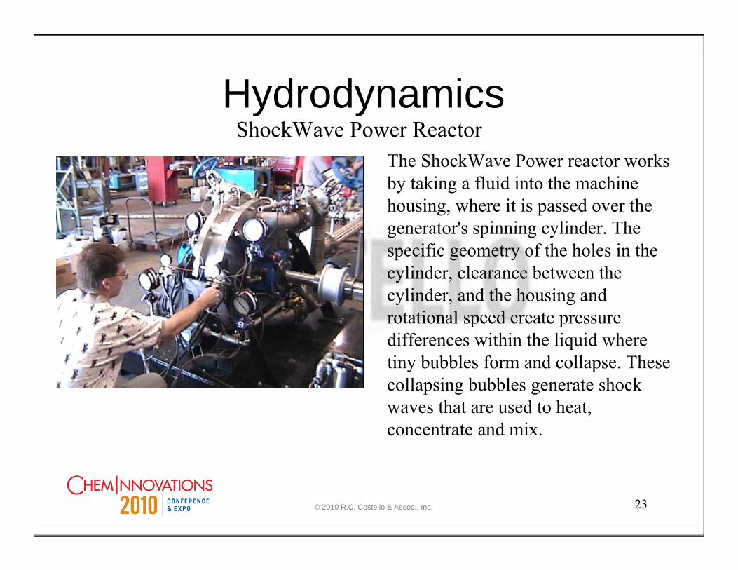
HydrodynamicsShockWave Power Reactor
The ShockWave Power reactor works by taking a fluid into the machine housing, where it is passed over the generator's spinning cylinder. The specific geometry of the holes in the cylinder, clearance between the cylinder, and the housing and rotational speed create pressure differences within the liquid where tiny bubbles form and collapse. These collapsing bubbles generate shock waves that are used to heat, concentrate and mix.
© 2010 R.C. Costello & Assoc., Inc.

24
HydrodynamicsShockWave Power Reactor
Mixing capabilities of the SPRat slow speeds.
Mixing at higher speeds
© 2010 R.C. Costello & Assoc., Inc.

25
Continuous Oscillatory Baffled Reactor (COBR)
© 2010 R.C. Costello & Assoc., Inc.

26
Continuous Oscillatory Baffled Reactor (COBR)
The basis of the technology is a tubular reactor with the presence of annular-baffles. The figure shows the mixing mechanism in a baffled cell . If a liquid is pushed up through the tube, eddies will be created around the baffles, enabling significant radial motion Likewise on a down stroke, eddies will be created on the opposite side and the intensity of eddy generation and cessation can precisely be controlled thus very effective mixing is created
© 2010 R.C. Costello & Assoc., Inc.

27
Continuous Oscillatory Baffled Reactor (COBR)
•Fewer side reactions
•Less losses through unnecessary changeovers and clean out
•Less out-of-spec product
© 2010 R.C. Costello & Assoc., Inc.
28
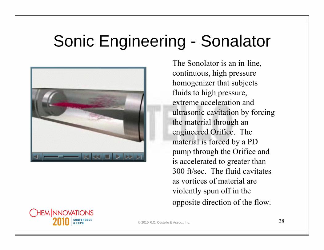
Sonic Engineering - SonalatorThe Sonolator is an in-line, continuous, high pressure homogenizer that subjects fluids to high pressure, extreme acceleration and ultrasonic cavitation by forcing the material through an engineered Orifice. The material is forced by a PD pump through the Orifice and is accelerated to greater than 300 ft/sec. The fluid cavitatesas vortices of material are violently spun off in the opposite direction of the flow.
© 2010 R.C. Costello & Assoc., Inc.

Jacketed Static Mixer
© 2010 R.C. Costello & Assoc., Inc.
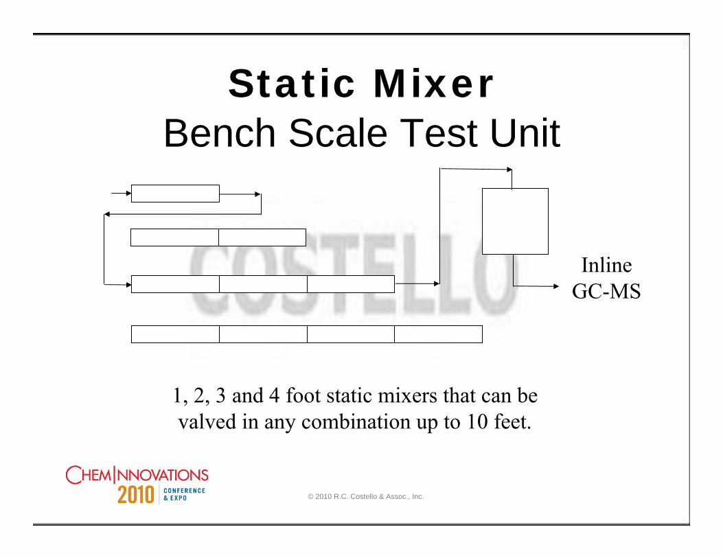
Static MixerBench Scale Test Unit
1, 2, 3 and 4 foot static mixers that can be valved in any combination up to 10 feet.
InlineGC-MS
© 2010 R.C. Costello & Assoc., Inc.
31
Jacketed Static Reactor
Low costEnhances Reaction RatesPerforms better than plug flow reactorJacketed for heat removalScales up
© 2010 R.C. Costello & Assoc., Inc.
32
Two or more distinct fluid streams moving in the same capillary at low Reynolds number . . . do not develop turbulence at the interface between them, or at the interface with the capillary walls. The only mechanism for mixing the components of such a stream is diffusion across the interface.
Chemical & Engineering News, July 5, 1999; Science, July 2, 1999
Microchannel Reactors
© 2010 R.C. Costello & Assoc., Inc.
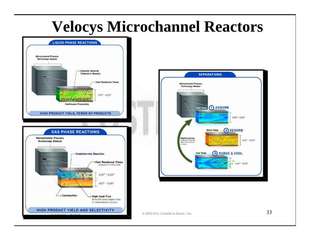
33
Velocys Microchannel Reactors
© 2010 R.C. Costello & Assoc., Inc.

34
Velocys Features↑ product yield & energy efficiency by improving heat & mass transfer performance ↓ capital costsEnhance catalyst productivityCost-effective debottlenecking & expansion Substantially reduce pollutant emissions Create new products by enabling optimal processing conditions not possible with conventional hardware
© 2010 R.C. Costello & Assoc., Inc.

35
Chart Energy & ChemicalsA macrochannel reactor and/ or heat
exchanger
http://www.chart-ind.com/app_ec_reactortech.cfm
© 2010 R.C. Costello & Assoc., Inc.

36
Reaction System SizingKinetic Rate Expression
1st order reversible2nd order reversible1st order irreversible2nd order irreversible
Reactor Equation
BatchCSTRPlug Flow
© 2010 R.C. Costello & Assoc., Inc.

37
Reactor EquationsBatch
CSTR
Plug Flow
Static Mixer – None
SPR Reactor – None
Microchannel Reactor –None
© 2010 R.C. Costello & Assoc., Inc.

38
Where Are We RegardingReactor Design & Scale Up?
Information voidBench Scale testing is crucial
Reduction in residence time compared to CSTR or plug flow reactor
Sometimes side reactions are minimizedRarely side reactions are amplified
What can we expect?
© 2010 R.C. Costello & Assoc., Inc.

39
Distillation
© 2010 R.C. Costello & Assoc., Inc.

40
LiquidFeed
VaporFeed
Vapor Outlet
LiquidOutletDrive
Shaft
RotatingElement
Higee Internal SchematicHigee - High Gravity Rotating Contactor
© 2010 R.C. Costello & Assoc., Inc.
41
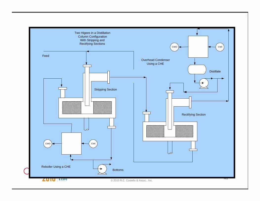
CWO CWI
CWO CWI
Feed
Distillate
Bottoms
Two Higees in a DistillationColumn Configuration
With Stripping andRectifying Sections
Stripping Section
Rectifying Section
Reboiler Using a CHE
Overhead CondenserUsing a CHE
© 2010 R.C. Costello & Assoc., Inc.
42
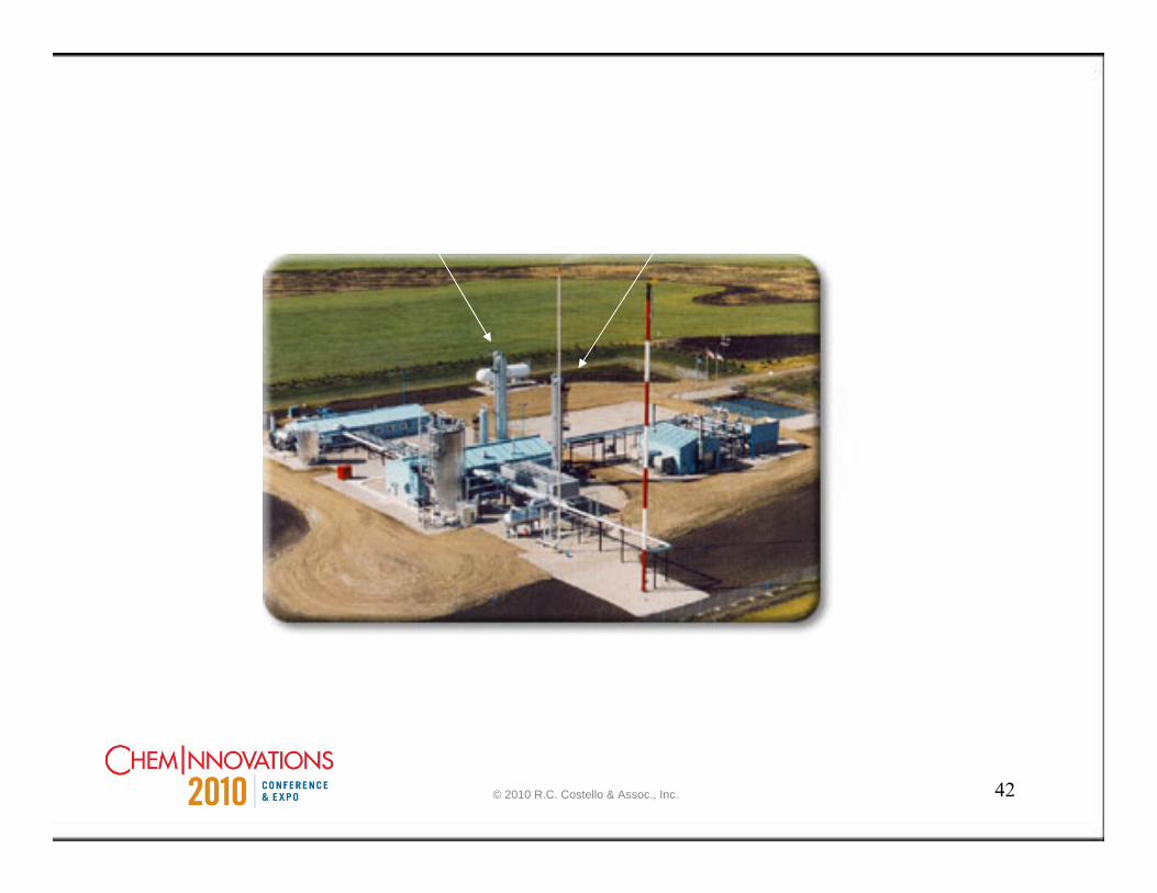
Amine Unit with Two Columns
© 2010 R.C. Costello & Assoc., Inc.

43
Before PI
© 2010 R.C. Costello & Assoc., Inc.

44
After PI
© 2010 R.C. Costello & Assoc., Inc.
45
Divided Wall Column•One divided-wall column can replace two or more conventional columns.
•The divided-wall column offers capital, energy and plot area savings compared to the conventional column configurations.
•The divided-wall column is applicable to some ternary separations where the mid boiling component is desired in high purity along with high purity lighter and heavier boiling products.
•It is estimated over 35 columns are in service.
•Used commercially so far in niche applications in fine chemicals, petrochemical, gas separation and refining industries
© 2010 R.C. Costello & Assoc., Inc.

46
Divided Wall Column
© 2010 R.C. Costello & Assoc., Inc.

47
Divided Wall Column
Over HeadProduct
Reflux
Vapor FromReboiler
Montz Dividing-Wall-Pak
Reflux Splitter
Side Product
BottomProduct
Montz-Pak
Montz-Pak
Montz Dividing-Wall-Pak
© 2010 R.C. Costello & Assoc., Inc.

48
Divided Wall Column
© 2010 R.C. Costello & Assoc., Inc.

49
Divided Wall Column
© 2010 R.C. Costello & Assoc., Inc.

50
Divided Wall ColumnReflux Splitter
© 2010 R.C. Costello & Assoc., Inc.

The iPod for distillationThe iPod for distillation
Diameter 0.5-6 mHeight 5-100 mWeight 1-100 ton
Modular systemMicrosieve stacksBox system
Today’s Distillation fluXXion HEC:High Efficiency Contactor
100 times smaller
© 2010 R.C. Costello & Assoc., Inc.
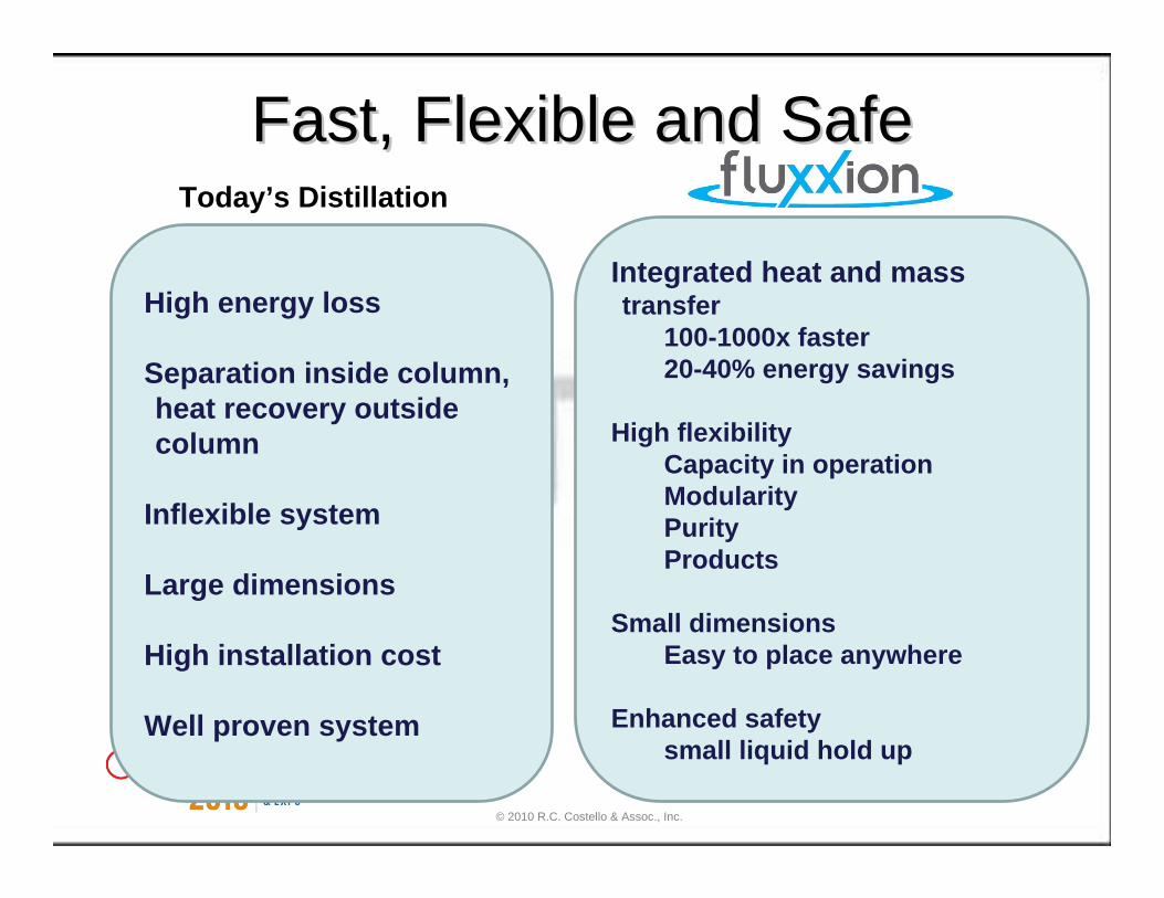
Fast, Flexible and SafeFast, Flexible and SafeToday’s Distillation
High energy loss
Separation inside column, heat recovery outside column
Inflexible system
Large dimensions
High installation cost
Well proven system
Integrated heat and mass transfer
100-1000x faster20-40% energy savings
High flexibilityCapacity in operationModularityPurityProducts
Small dimensionsEasy to place anywhere
Enhanced safetysmall liquid hold up
© 2010 R.C. Costello & Assoc., Inc.

Small, Flexible, SafeSmall, Flexible, Safe
5353
• Stable operation (large pressure differential)• No moving parts• Individual module/stack temperature control possible• High pressure operation possible (put module in autoclave!)
• Hazardous materials & pathways• capacity & purity flexibility• volume/height restricted situations• low gas volume stripping
© 2010 R.C. Costello & Assoc., Inc.

Page Page 5454
Proven ScienceProven Science
5 billion identical pores
0,45 micron diameter
1 micron membrane thickness
UNIQUE MICROSIEVE TECHNOLOGY
15 cm diameter
0,7 mm thick
High volume production
© 2010 R.C. Costello & Assoc., Inc.

PROOF:PROOF: ultra short HTUultra short HTUOLOLStripping MTBE from water by nitrogen at Stripping MTBE from water by nitrogen at ambient conditions was used as a test system for ambient conditions was used as a test system for performance evaluation purposes. Inlet performance evaluation purposes. Inlet concentration of MTBE , different flow rates for concentration of MTBE , different flow rates for liquid and gas were varied in a wide range. The liquid and gas were varied in a wide range. The best efficiency was achieved in all cases at best efficiency was achieved in all cases at lowest liquid flow rate, and tended to decrease lowest liquid flow rate, and tended to decrease progressively with increasing liquid flow rate, i.e. progressively with increasing liquid flow rate, i.e. decreasing residence time. Gas flow rate decreasing residence time. Gas flow rate exhibited practically no effect on separation, exhibited practically no effect on separation, indicating that this system also can be considered indicating that this system also can be considered as fully controlled by liquid side mass transfer as fully controlled by liquid side mass transfer resistance. Since the value of the overall liquid resistance. Since the value of the overall liquid side based volumetric mass transfer coefficient side based volumetric mass transfer coefficient was almost constant, the overall height of liquid was almost constant, the overall height of liquid side transfer unit (side transfer unit (HTUoLHTUoL) increased nearly ) increased nearly proportionally and ranged 0.5proportionally and ranged 0.5--4 cm (!). The 4 cm (!). The corresponding heights equivalent to a theoretical corresponding heights equivalent to a theoretical plate (HETP values) were plate (HETP values) were 2 to 10 cm2 to 10 cm (!). These (!). These numbers indicate a high mass transfer efficiency, numbers indicate a high mass transfer efficiency, an order of magnitude above that experienced an order of magnitude above that experienced with common types and sizes of corrugated sheet with common types and sizes of corrugated sheet structured packing in similar applications.structured packing in similar applications.
© 2010 R.C. Costello & Assoc., Inc.

56
Energy Reduction Alternatives in the Fuel
Ethanol IndustryUse of Multieffect columns to replace the distillation columnsCan reduce the energy costs by
$.05/ gallon
© 2010 R.C. Costello & Assoc., Inc.

57
Multi Effect Distillation
© 2010 R.C. Costello & Assoc., Inc.

58
Heat Transfer
© 2010 R.C. Costello & Assoc., Inc.

59
KlarexTechnology
Self CleaningHeat Exchanger
© 2010 R.C. Costello & Assoc., Inc.

60
Modified Reboiler
© 2010 R.C. Costello & Assoc., Inc.
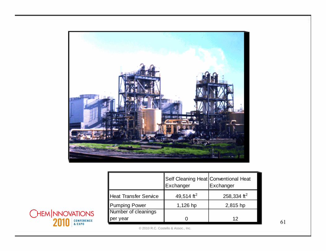
61
Self Cleaning Heat Exchanger
Conventional Heat Exchanger
Heat Transfer Service 49,514 ft2 258,334 ft2
Pumping Power 1,126 hp 2,815 hpNumber of cleanings per year 0 12
© 2010 R.C. Costello & Assoc., Inc.

62
Alfa Laval Compact Heat Exchangers
Cube Shaped Compact Heat Exchangers (CHEs) with high square foot areas per cubic
foot volume© 2010 R.C. Costello & Assoc., Inc.

63
Cut Away Views
© 2010 R.C. Costello & Assoc., Inc.
64
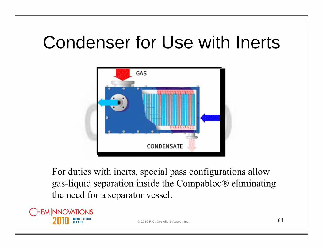
Condenser for Use with Inerts
For duties with inerts, special pass configurations allow gas-liquid separation inside the Compabloc® eliminating the need for a separator vessel.
© 2010 R.C. Costello & Assoc., Inc.

65
Multifunctional Reactors
• In House Technologies• Commercially Available© 2010 R.C. Costello & Assoc., Inc.

66
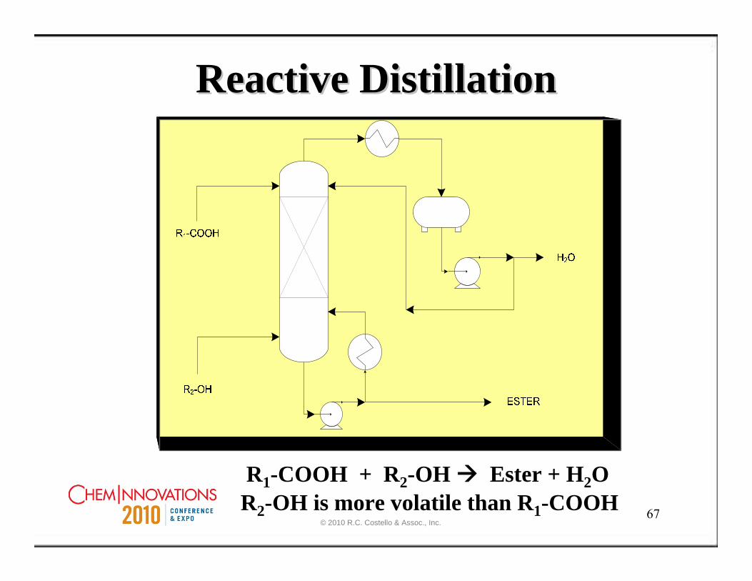
Reactive DistillationReactive Distillation
© 2010 R.C. Costello & Assoc., Inc.
67
R1-COOH + R2-OH Ester + H2OR2-OH is more volatile than R1-COOH
Reactive DistillationReactive Distillation
© 2010 R.C. Costello & Assoc., Inc.
68
Reactive DistillationColumn Internals
•Random packing
•Trays with high weirs
•Structured packing
© 2010 R.C. Costello & Assoc., Inc.
69
Reactive DistillationCatalysts
•On Trays Sewn into Pillows
•Coating on Random Packing
•Coating Structured Packing
© 2010 R.C. Costello & Assoc., Inc.

70
Other Methods
© 2010 R.C. Costello & Assoc., Inc.

71
TFE Extraction Technology
FF F
FCCH
H
1,1,1,2 TETRAFLUORO ETHANE
MW 102BP -26.5 °C (-15.7°F)DENSITY 1.2 @ 5 bar, 20 °C
( 72.5 psia/ 68 °F)SUPERCRITICAL POINT 42 bar/98 °C
( 608 psia/ 208.4 °F)
© 2010 R.C. Costello & Assoc., Inc.

72
ODORLESS & COLORLESS LIQUIDS
LIQUIFY AT 5 BAR PRESSURE, AT AMBIENT TEMPERATURE
RECYCLABLE
LEAVE NO RESIDUES
CHEMICALLY INERT
Advantages of 1,1,1,2 –Tetrafluoroethane & its Mixtures
NON FLAMMABLE
NON CORROSIVE
NON TOXIC
NEUTRAL pH
ENVIRONMENTALLY FRIENDLY
APPROVED FOR USE IN FOOD PROCESSING & FDA FOR MDIs
© 2010 R.C. Costello & Assoc., Inc.
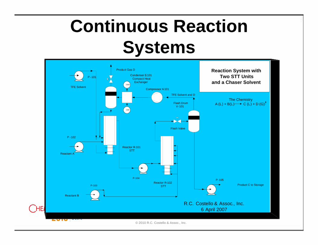
Continuous Reaction Systems
Condenser E-101Compact Heat
Exchanger
Reactor R-101STT
Reactant A
TFE Solvent
Reaction System with Two STT Units
and a Chaser Solvent
R.C. Costello & Assoc., Inc. 6 April 2007
Product C to Storage
P -101
P -102
P-103
P-104P- 105
Flash DrumV-101
Reactor R-102STT
Reactant B
CWO
CWI
TFE Solvent and D
Compressor K-101
The ChemistryA (L) + B(L) C (L) + D (G)
Product Gas D
Flash Valve
© 2010 R.C. Costello & Assoc., Inc.
Continuous Reaction SystemsWith Nanoparticle Catalysts
•A nanoparticle (or nanopowder or nanocluster or nanocrystal) is a microscopic particle with at least one dimension less than 100 nm.
•Filtration doesn’t work for separation of nanoparticles from fluids. Bag filters are effective down to 0.5 microns. (1 micron = 1000 nm)
•Surface area of the material dominates the properties in lieu of the bulk properties. Think of a nanoparticle as a molecule.
•Surface area per mg of material is enormous and since catalysis is a surface phenomenon then nanoparticles are ideal
© 2010 R.C. Costello & Assoc., Inc.

Continuous Reaction System With Nanoparticle Catalyst
© 2010 R.C. Costello & Assoc., Inc.
76
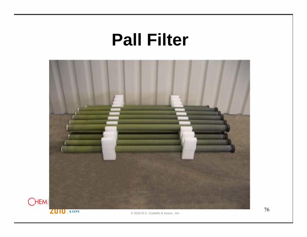
Pall Filter
© 2010 R.C. Costello & Assoc., Inc.

77
Pall Filter•Two-step flue gas cleaning processes consisting of a particle filter with a subsequent low-dust SCR (Selective Catalytic Reduction) catalyst unit or of a high dust SCR catalyst unit
•The catalytic filter is a hot gas filter equipped with catalytic filter elements and designed for a catalyst operating temperature of 300°C. The catalytic filter elements are catalytically activated ceramic hot gas filter elements consisting of SiC, which provide a highly efficient particle separation by means of a fine filtering outer membrane.
•The catalytic activation of the elements is accomplished by impregnation of the 10 mm thick porous filter element wall with a SCR catalyst with the composition TiO2-V2O5-WO3.
© 2010 R.C. Costello & Assoc., Inc.
78
Why Intensify?Capital CostsOperating CostsMaintenance CostsPlant Footprint & Profile
Facilitate scale upProvide basis for rapid development of products & processes ( Time Line)
SafetyEnvironmental Impact
© 2010 R.C. Costello & Assoc., Inc.

What Processes Are Candidates for PI?
• New chemistries.• Existing old plants where the number of
unit ops can be reduced. If your considering a rebuild where a distillation step can be eliminated.
• Existing plants with a severe downtime issue.
• Market requires Improving purity of your product.
© 2010 R.C. Costello & Assoc., Inc.

80
Before vs. After PI
Source: Chemical Engineering Progress (CEP) Magazine, January 2000.Before
After
© 2010 R.C. Costello & Assoc., Inc.