overview of the resourcesat-1 (irs-p6) - usgs · overview of the resourcesat-1 (irs-p6) gyanesh...
TRANSCRIPT

U.S. Department of the Interior
U.S. Geological Survey
Overview of the Resourcesat-1 (IRS-P6)Overview of the Resourcesat-1 (IRS-P6)
Gyanesh Chander, SAICContract employee under U.S. Geological Survey contract 03CRCN0001
2
OutlineOutline
BackgroundOrbit and PayloadSensor OverviewRSR Profiles comparisonData ProductsConversion to RadianceReferences
3
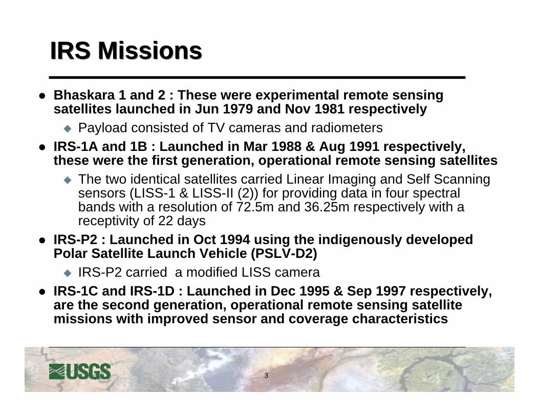
IRS MissionsIRS MissionsBhaskara 1 and 2 : These were experimental remote sensing satellites launched in Jun 1979 and Nov 1981 respectively
Payload consisted of TV cameras and radiometersIRS-1A and 1B : Launched in Mar 1988 & Aug 1991 respectively, these were the first generation, operational remote sensing satellites
The two identical satellites carried Linear Imaging and Self Scanning sensors (LISS-1 & LISS-II (2)) for providing data in four spectral bands with a resolution of 72.5m and 36.25m respectively with a receptivity of 22 days
IRS-P2 : Launched in Oct 1994 using the indigenously developed Polar Satellite Launch Vehicle (PSLV-D2)
IRS-P2 carried a modified LISS cameraIRS-1C and IRS-1D : Launched in Dec 1995 & Sep 1997 respectively, are the second generation, operational remote sensing satellite missions with improved sensor and coverage characteristics

4
IRS MissionsIRS Missions
IRS-P3 : Launched in Apr 1996 by the PSLV-D3The payload consists of two imaging sensors & one non-imaging sensorThe Wide Field Sensor (WiFS) sensor is providing data with a spatial resolution of 188m in three spectral bands, in the VNIR regions, with a swath of 810 KmThe other two sensors on-board are a Modular Opto-electronic Scanner (MOS) and an X-ray astronomy payloadWiFS and MOS data products are being disseminated to users
OCEANSAT-1 (IRS-P4) : Launched in May 1999The payload consists of an Ocean Color Monitor (OCM) operating in eight spectral in the VNIR region and a Multi-frequency Scanning Microwave Radiometer (MSMR), operating in four frequencies namely 6.60, 10.61, 18 and 21 GHzThese sensors are providing data for measuring the physical and biological parameters of oceans

5
Resourcesat-1 (IRS P6)Resourcesat-1 (IRS P6)The RESOURCSAT-1 satellite was launched in to the polar sun-synchronous orbit (altitude of 817 km) by PSLV-C5 launch vehicle on October 17, 2003 with a design life of 5 yearsRESOURCSAT-1 is also called IRS-P6
Most advanced Remote Sensing Satellite built by ISROTenth satellite of ISRO in IRS seriesOther ISRO operational satellites are IRS 1-C, IRS 1-D, IRS P-2, IRS P-3
6
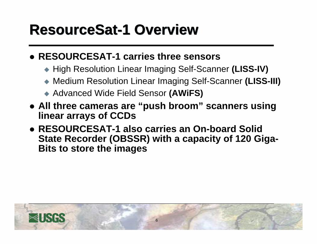
ResourceSat-1 OverviewResourceSat-1 Overview
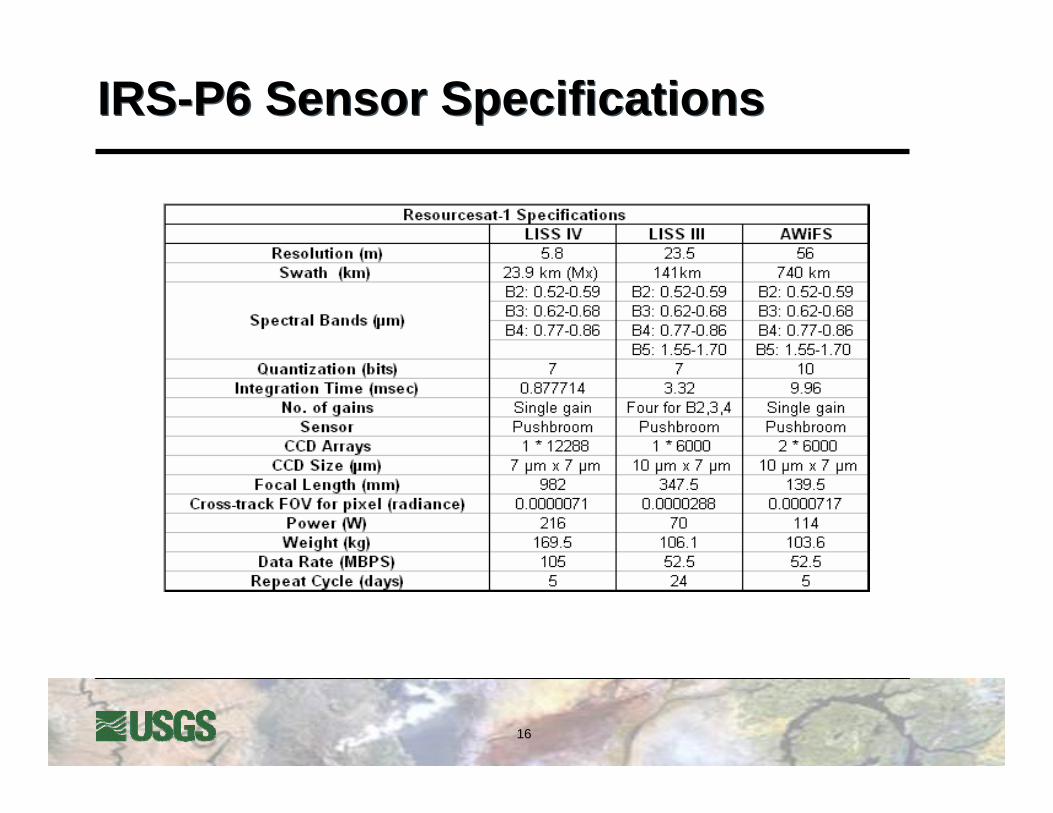
RESOURCESAT-1 carries three sensorsHigh Resolution Linear Imaging Self-Scanner (LISS-IV)Medium Resolution Linear Imaging Self-Scanner (LISS-III)Advanced Wide Field Sensor (AWiFS)
All three cameras are “push broom” scanners using linear arrays of CCDsRESOURCESAT-1 also carries an On-board Solid State Recorder (OBSSR) with a capacity of 120 Giga-Bits to store the images


8
Advanced Wide Field Sensor (AWiFS)Advanced Wide Field Sensor (AWiFS)The AWiFS with twin cameras is a moderate-resolution sensor offering a GSD of 56m at nadirQuantization: 10 bitsCombined ground swath is 740km with five day repeat cycleOperates in four spectral bands – three VNIR one SWIR
VITAL FACTS:• Instrument: Pushbroom• Bands (4): 0.52-0.59, 0.62-0.68, 0.77-0.86, 1.55-1.70 µm• Spatial Resolution: 56 m (near nadir), 70 m (near edge)• Radiometric Resolution: 10 bit• Swath: 740 km• Repeat Time: 5 days• Design Life: 5 years
9
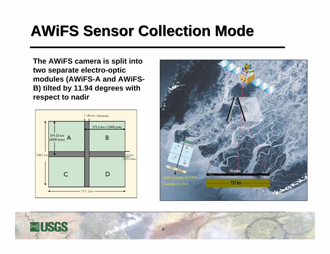
AWiFS Sensor Collection ModeAWiFS Sensor Collection Mode
The AWiFS camera is split into two separate electro-optic modules (AWiFS-A and AWiFS-B) tilted by 11.94 degrees with respect to nadir
10
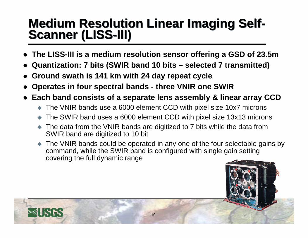
Medium Resolution Linear Imaging Self-Scanner (LISS-III)Medium Resolution Linear Imaging Self-Scanner (LISS-III)The LISS-III is a medium resolution sensor offering a GSD of 23.5m Quantization: 7 bits (SWIR band 10 bits – selected 7 transmitted)Ground swath is 141 km with 24 day repeat cycleOperates in four spectral bands - three VNIR one SWIREach band consists of a separate lens assembly & linear array CCD
The VNIR bands use a 6000 element CCD with pixel size 10x7 micronsThe SWIR band uses a 6000 element CCD with pixel size 13x13 micronsThe data from the VNIR bands are digitized to 7 bits while the data from SWIR band are digitized to 10 bitThe VNIR bands could be operated in any one of the four selectable gains by command, while the SWIR band is configured with single gain setting covering the full dynamic range

11
LISS-III In-flight CalibrationLISS-III In-flight Calibration
The In-flight calibration of the LISS-III camera is carried out using four LEDs per CCD in VNIR bands and 6 LEDs for the SWIR bandLEDs are operated in pulsed modePulse duration during which these LEDs are ON is varied in specific steps
Each LED has a cylindrical lens to distribute the light intensity onto the CCDEach calibration cycle consists of 2048 lines providing six non zero intensity levelsEach intensity level is generated sequentially by LED-1 ON, LED-2 ON and LED-1 and 2 ON
12
High Resolution Linear Imaging Self-Scanner (LISS-IV)High Resolution Linear Imaging Self-Scanner (LISS-IV)
The LISS-IV is the highest-resolution sensor offering a GSD of 5.8m at nadirQuantization: 10 bits (selected 7 bits transmitted)Ground swath is 23 or 70 km with 5 days repeat cycle
Steerable upto +/- 26o across track to obtain stereoscopic imageryOperates in three spectral VNIR bands
A single telescope & lens assembly is used for all bandsBand 3 (red) is placed closest to nadir, while band 2 looks ahead and band 4 looks behind the satellite velocity vector
The 12000 pixel CCD array for each band is separated into odd & even pixel, arranged in two rows with a distance of 35 microns (5 scan lines) between them
13
LISS-IV Quantization 7 bitsLISS-IV Quantization 7 bitsThe image data is digitized to 10 bits onboard the satellite butonly 7 bits are transferred from satellite to ground
There is a fixed gain setting used to produce the original 10-bit signalThere is no dynamic decision-making on the part of the onboard data handling system
The selection of which 7 bits to transfer from the 10-bit signal is performed by the satellite operator during collection taskingThe ground operators select which 7 bits are extracted by specifying one of four 'gain' settings 0-6, 1-7, 2-8, or 3-9
Sensor metadata provided with the image product indicates what ‘gain’setting (i.e., bit selection) was used for the scene
The product are delivered as 8-bitThe ground processing system applies a 7-bit LUT for radiometric calibration of the 7 bit data, then they insert a zero bit at the least significant bitThis pushes the DN range from 0-127 to 2-254The end-user still end up getting DNs of 1 and 255, however, because of cubic convolution resampling
14
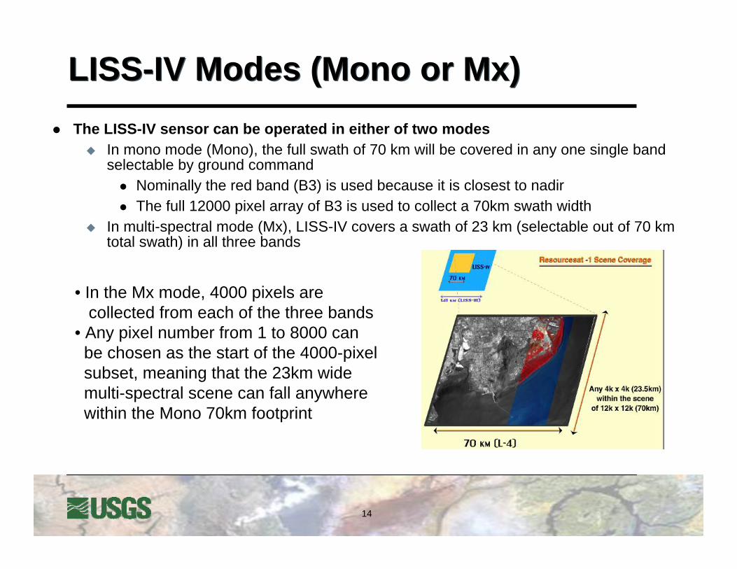
LISS-IV Modes (Mono or Mx)LISS-IV Modes (Mono or Mx)The LISS-IV sensor can be operated in either of two modes
In mono mode (Mono), the full swath of 70 km will be covered in any one single band selectable by ground command
Nominally the red band (B3) is used because it is closest to nadirThe full 12000 pixel array of B3 is used to collect a 70km swath width
In multi-spectral mode (Mx), LISS-IV covers a swath of 23 km (selectable out of 70 km total swath) in all three bands
• In the Mx mode, 4000 pixels are collected from each of the three bands
• Any pixel number from 1 to 8000 can be chosen as the start of the 4000-pixel subset, meaning that the 23km wide multi-spectral scene can fall anywhere within the Mono 70km footprint

15
LISS-IV In-flight CalibrationLISS-IV In-flight Calibration
Pre-launch light transfer characteristics (LTC) of the overall Payload system are generated in the lab
Performance parameters like spectral response, dark current, dynamic range, temperature and linearity are measuredLTC data is used for radiometric corrections of the image data
However, to monitor the long term performance of the detector and processing electronics, an in-flight calibration scheme is implemented using LEDs
Eight LEDs are positioned in front of the CCD (without obstructing the light path during imaging)These LEDs are driven with a constant current and the integration time is varied to get 16 exposure levels, covering the dynamic range in a sequential manner (This sequence repeats in a cyclic form)
16
IRS-P6 Sensor SpecificationsIRS-P6 Sensor Specifications
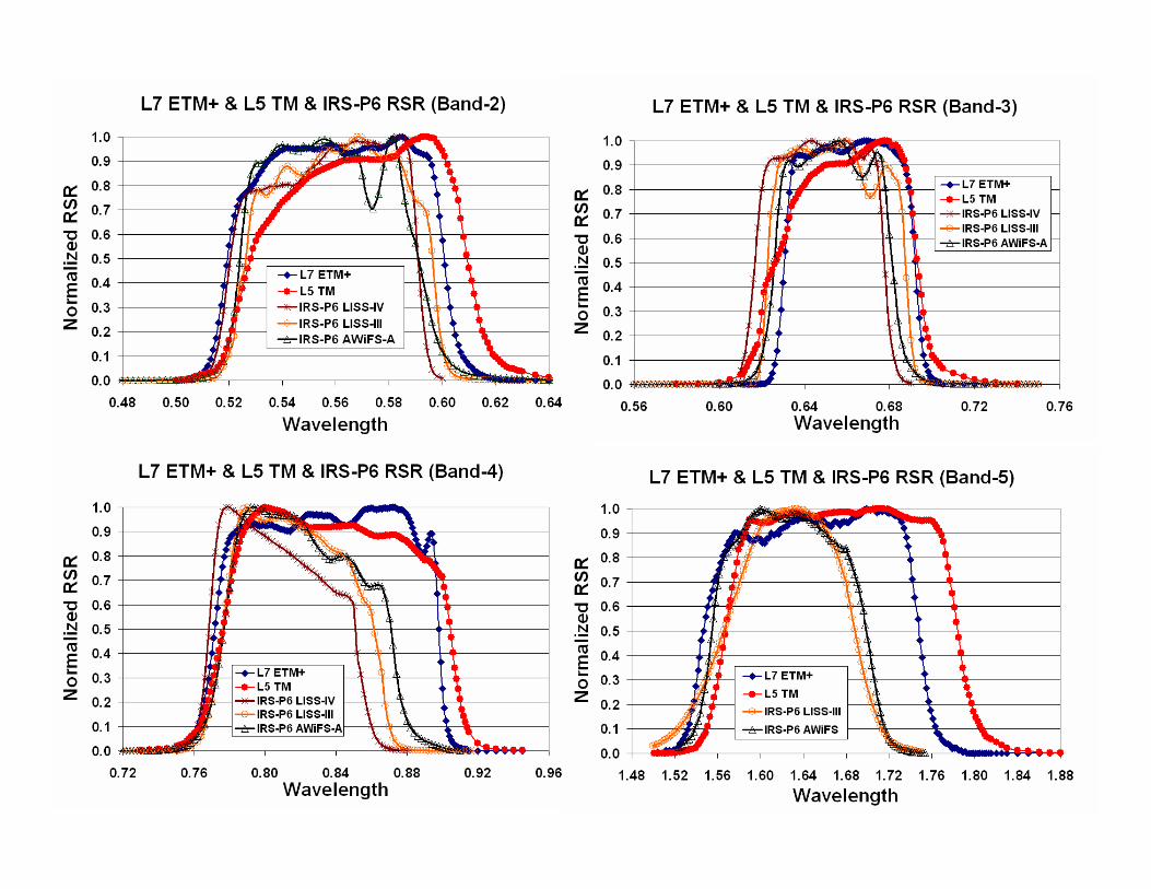
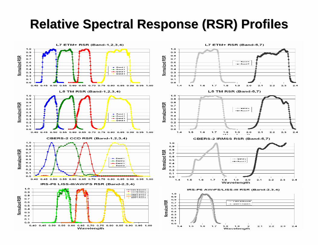
Relative Spectral Response (RSR) ProfilesRelative Spectral Response (RSR) Profiles

19
Data ProductsData Products
Space Imaging (now GeoEye) was granted a license to receive & distribute AWiFS imagery from their ground station in Oklahoma (Jan. 2005)
20
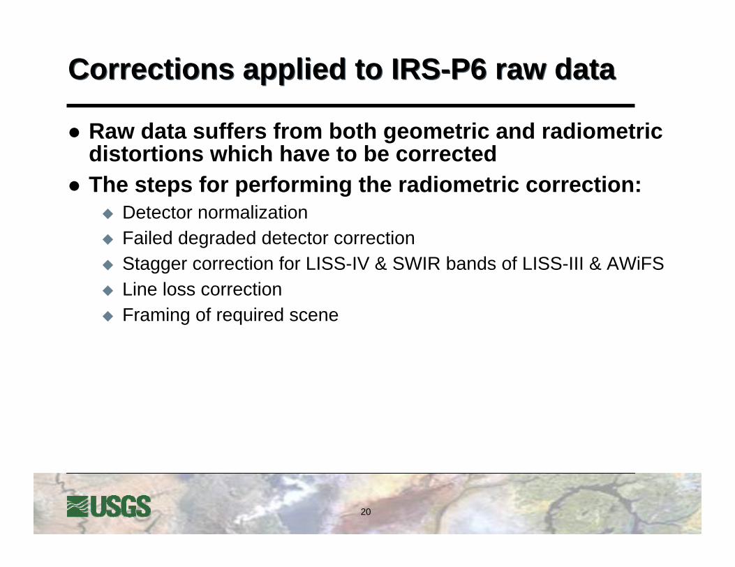
Corrections applied to IRS-P6 raw dataCorrections applied to IRS-P6 raw data
Raw data suffers from both geometric and radiometric distortions which have to be correctedThe steps for performing the radiometric correction:
Detector normalizationFailed degraded detector correctionStagger correction for LISS-IV & SWIR bands of LISS-III & AWiFSLine loss correctionFraming of required scene
21
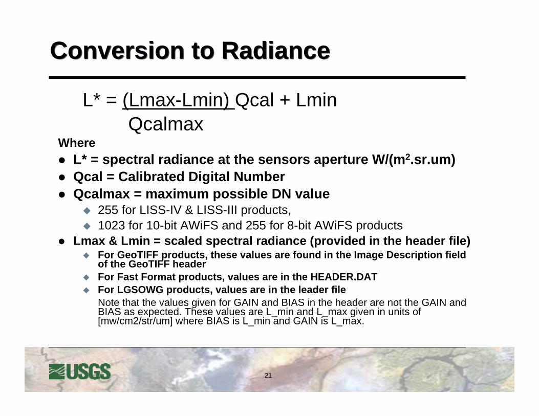
Conversion to RadianceConversion to Radiance
L* = (Lmax-Lmin) Qcal + LminQcalmax
WhereL* = spectral radiance at the sensors aperture W/(m2.sr.um)Qcal = Calibrated Digital NumberQcalmax = maximum possible DN value
255 for LISS-IV & LISS-III products, 1023 for 10-bit AWiFS and 255 for 8-bit AWiFS products
Lmax & Lmin = scaled spectral radiance (provided in the header file)For GeoTIFF products, these values are found in the Image Description field of the GeoTIFF headerFor Fast Format products, values are in the HEADER.DAT For LGSOWG products, values are in the leader fileNote that the values given for GAIN and BIAS in the header are not the GAIN and BIAS as expected. These values are L_min and L_max given in units of [mw/cm2/str/um] where BIAS is L_min and GAIN is L_max.
22
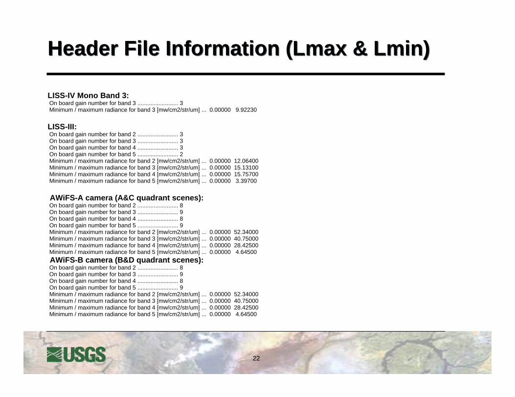
Header File Information (Lmax & Lmin)Header File Information (Lmax & Lmin)
LISS-IV Mono Band 3:On board gain number for band 3 ......................... 3Minimum / maximum radiance for band 3 [mw/cm2/str/um] ... 0.00000 9.92230
LISS-III:On board gain number for band 2 ......................... 3On board gain number for band 3 ......................... 3On board gain number for band 4 ......................... 3On board gain number for band 5 ......................... 2Minimum / maximum radiance for band 2 [mw/cm2/str/um] ... 0.00000 12.06400Minimum / maximum radiance for band 3 [mw/cm2/str/um] ... 0.00000 15.13100Minimum / maximum radiance for band 4 [mw/cm2/str/um] ... 0.00000 15.75700Minimum / maximum radiance for band 5 [mw/cm2/str/um] ... 0.00000 3.39700
AWiFS-A camera (A&C quadrant scenes):On board gain number for band 2 ......................... 8On board gain number for band 3 ......................... 9On board gain number for band 4 ......................... 8On board gain number for band 5 ......................... 9Minimum / maximum radiance for band 2 [mw/cm2/str/um] ... 0.00000 52.34000Minimum / maximum radiance for band 3 [mw/cm2/str/um] ... 0.00000 40.75000Minimum / maximum radiance for band 4 [mw/cm2/str/um] ... 0.00000 28.42500Minimum / maximum radiance for band 5 [mw/cm2/str/um] ... 0.00000 4.64500AWiFS-B camera (B&D quadrant scenes):On board gain number for band 2 ......................... 8On board gain number for band 3 ......................... 9On board gain number for band 4 ......................... 8On board gain number for band 5 ......................... 9Minimum / maximum radiance for band 2 [mw/cm2/str/um] ... 0.00000 52.34000Minimum / maximum radiance for band 3 [mw/cm2/str/um] ... 0.00000 40.75000Minimum / maximum radiance for band 4 [mw/cm2/str/um] ... 0.00000 28.42500Minimum / maximum radiance for band 5 [mw/cm2/str/um] ... 0.00000 4.64500
23
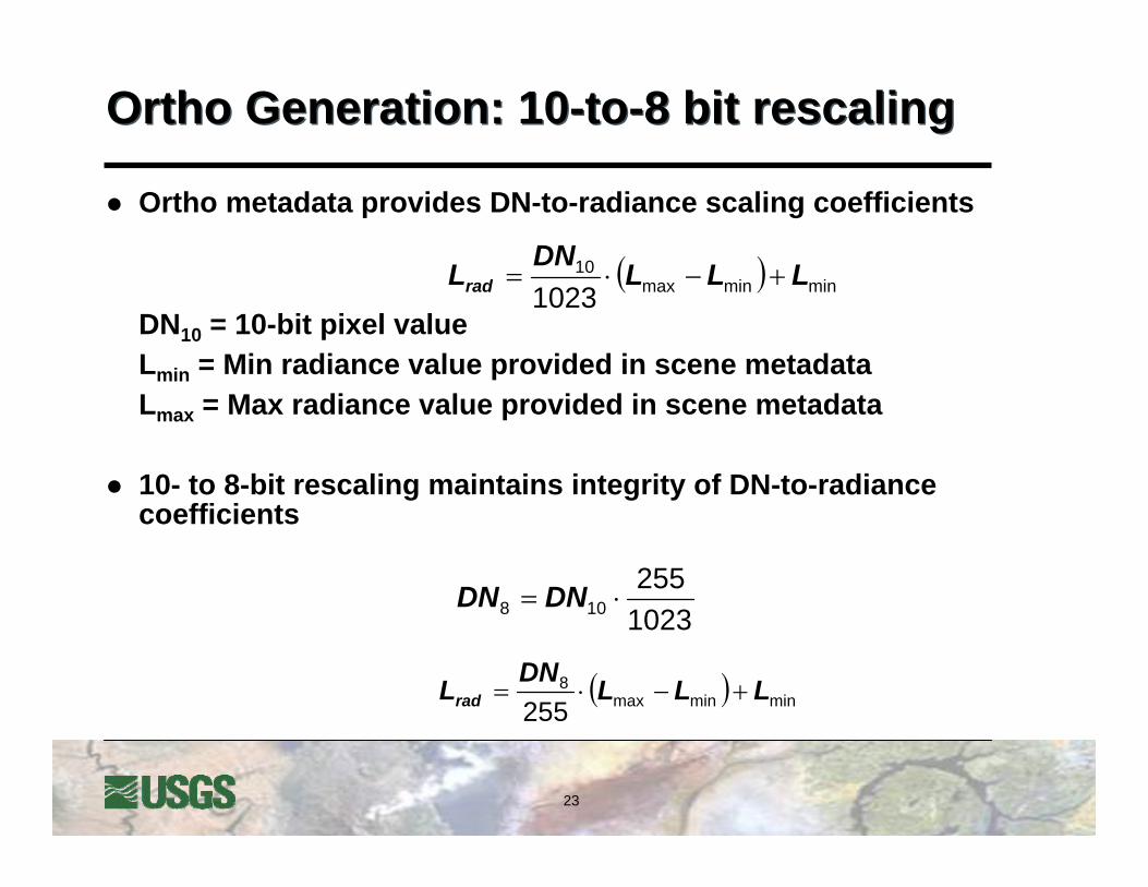
Ortho Generation: 10-to-8 bit rescalingOrtho Generation: 10-to-8 bit rescaling
Ortho metadata provides DN-to-radiance scaling coefficients
DN10 = 10-bit pixel valueLmin = Min radiance value provided in scene metadataLmax = Max radiance value provided in scene metadata
10- to 8-bit rescaling maintains integrity of DN-to-radiance coefficients
( ) minminmax10
1023LLLDNLrad +−⋅=
1023255
108 ⋅= DNDN
( ) minminmax8
255LLLDNLrad +−⋅=
24
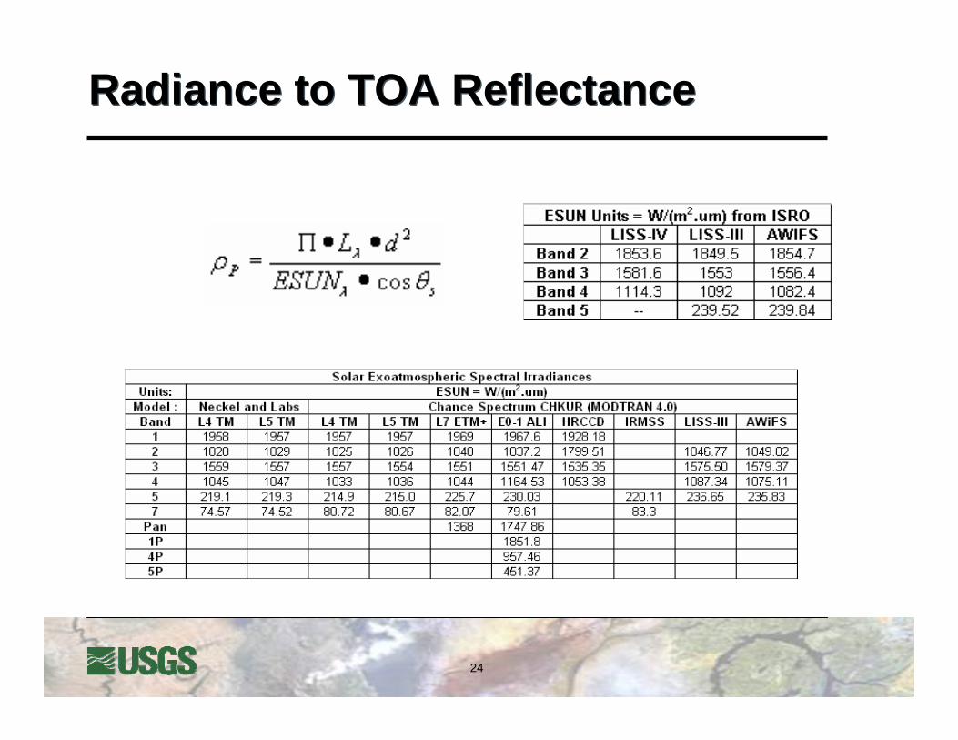
Radiance to TOA Reflectance Radiance to TOA Reflectance

25
Resourcesat-1 IGSsResourcesat-1 IGSs
There is a new IRS-P6 ground station coming up in UAE

26
IRS-IC and ID IGSIRS-IC and ID IGS
27
ReferencesReferencesWorld Wide Web (WWW)
http://www.isro.org/http://www.nrsa.gov.in/index.html/ http://www.spaceimaging.com/products/
DocumentsIRS-P6 Data User’s HandbookIRS-1D Data User’s HandbookIRS Program: An Overview