overview of thermal desorption technology
TRANSCRIPT
Approved for public release; distribution is unlimited.
Contract ReportCR 98.008-ENV
NAVAL FACILITIES ENGINEERING SERVICE CENTERPort Hueneme, California 93043-4370
OVERVIEW OF THERMALDESORPTION TECHNOLOGY
An Investigation Conducted by
Foster Wheeler Environmental Corporation
and
Battelle Corporation
June1998
Printed on recycled paper
ii
This report is a work prepared for the United States Government by Battelle and Foster WheelerEnvironmental Corporation. In no event shall either the United States Government, Battelle, or
Foster Wheeler Environmental Corporation have any responsibility or liability for anyconsequences of any use, misuse, inability to use, or reliance on the information containedherein, nor does either warrant or otherwise represent in any way the accuracy, adequacy,
efficacy, or applicability of the contents hereof.
The vendors and products, including the equipment, system components, and other materialsidentified in this report, are primarily for information purposes only. Although Battelle and
Foster Wheeler Environmental Corporation may have used some of these vendors and productsin the past, mention in this report does not constitute a recommendation for using these vendors
or products.
iii
CONTENTS
Section 1.0: INTRODUCTION................................................................................................... 1
Section 2.0: DEFINITION OF THERMAL DESORPTION...................................................... 2
2.1 Technological Description of Thermal Desorption............................................................... 22.2 Regulatory Perspective of Thermal Desorption.................................................................. 3
Section 3.0: APPLICABILITY OF THERMAL DESORPTION SYSTEMS............................ 6
Section 4.0: OVERVIEW OF VARIOUS TYPES OF THERMAL DESORPTIONSYSTEMS............................................................................................................. 10
4.1 Continuous-Feed Systems — Direct Contact ................................................................... 104.2 Continuous-Feed Systems — Indirect Contact ................................................................. 134.3 Batch-Feed Systems — Heated Oven ................................................................................ 154.4 Batch-Feed Systems — HAVE System........................................................................... 164.5 Batch-Feed Systems — In Situ Systems: Thermal Blanket and Thermal Well................ 184.6 Batch-Feed Systems — In Situ Systems: Enhanced Soil Vapor Extraction ....................... 19
Section 5.0: DESIGN AND PERFORMANCE CHARACTERISTICS .................................. 20
Section 6.0: COST INFORMATION........................................................................................ 23
6.1 Thermal Desorption Cost Information ................................................................................ 236.2 Thermal Desorption Cost Compared to Costs for Alternative Technologies ................... 25
Section 7.0: SUMMARY .......................................................................................................... 26
Section 8.0: REFERENCES...................................................................................................... 27
FIGURES
Figure 1. Generic Thermal Desorption Process ............................................................................. 2Figure 2. Thermal Desorption Technology Selection Decision Tree ............................................ 8Figure 3. First Generation—Direct-Contact Thermal Desorption Process.................................. 11Figure 4. Second Generation—Direct-Contact Thermal Desorption Process ............................. 12Figure 5. Third Generation—Direct-Contact Thermal Desorption Process ................................ 13Figure 6. Indirect-Contact Rotary Dryer Thermal Desorption Process ....................................... 14Figure 7. Typical Indirect-Contact Thermal Screw Thermal Desorption Process....................... 15Figure 8. Batch-Feed Thermal Desorption System—Indirect-Contact Heated Oven.................. 16Figure 9. Batch-Feed Thermal Desorption System—Direct-Contact HAVE System ................. 17

iv
TABLES
Table 1. Effectiveness of Thermal Desorption on General Contaminant Groupsfor Soil,Sludge, Sediments, and Filter Cakes................................................................ 6
Table 2. Typical Cost Information from Recent Literature ...................................................... 24Table 3. Cost Comparison Data for Different Project Sizes ..................................................... 24Table 4. Thermal Desorption Compared to Alternative Technologies ..................................... 25
v
ACRONYMS AND ABBREVIATIONS
BADCAT Bay Area Defense Conversion Action TeamBCDP base-catalyzed decomposition processBTEX benzene, toluene, ethylbenzene, and xylenes
CEM continuous emissions monitoringCERCLA Comprehensive Environmental Response, Compensation, and LiabilityActCY cubic yards
EPA (U.S.) Environmental Protection Agency
FRP fiberglass-reinforced plasticFWENC Foster Wheeler Environmental Corporation
HAVE hot-air vapor extractionHCl hydrochloric acidHTTD high-temperature thermal desorption
LPG liquified petroleum gasLTEV low-temperature enhanced volatilizationLTTD low-temperature thermal desorption
NFESC Naval Facilities Engineering Service Center
PAH polycyclic aromatic hydrocarbonPCB polychlorinated biphenyl
RCRA Resource Conservation and Recovery ActRFP request for proposalsRITS Remediation Innovative Technology SeminarRPM Remediation Project Manager
SVE soil vapor extractionSVOC semivolatile organic compound
TD thermal desorption/desorberTPH total petroleum hydrocarbonTR technical report
VOC volatile organic compound
1
Section 1.0: INTRODUCTION
During mid-July and mid-August 1997, the Naval Facilities Engineering Service Center(NFESC) conducted a series of 1-day environmental technology seminars for personnel fromNaval installations.
The program was entitled the “Remediation Innovative Technology Seminar” (RITS),and its purpose was to provide various Navy and Naval contractor personnel with an overviewand description of the current status of several remedial technologies. One of the technologiesdescribed was thermal desorption. Information was compiled from a practical and appliedstandpoint, to familiarize Remediation Project Managers (RPMs) and other field personnel withthe thermal desorption technology. The scope of the program did not include coverage ofthermal treatment theory and detailed design parameters.
Presentation materials for this segment of the RITS were developed by Foster WheelerEnvironmental Corporation (FWENC) through a subcontract with Battelle Memorial Institute,the prime contractor to NFESC. FWENC staff conducted the thermal desorption segment at theRITS.
This paper is intended to be a concise, narrative discussion of the salient points of thethermal desorption presentation. Further details are contained in the hard copy of the presenta-tion slides, distributed to each of the attendees in the form of the RITS course manual. Addi-tional copies of the manual are available through NFESC. An application guide for the thermaldesorption technology is being developed and will include further information on implementingthis technology. This document will be available from NFESC at Port Hueneme, California.
2
Section 2.0: DEFINITION OF THERMAL DESORPTION
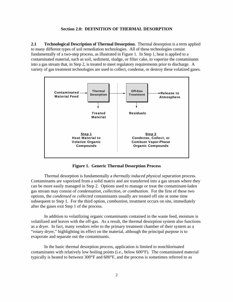
2.1 Technological Description of Thermal Desorption. Thermal desorption is a term appliedto many different types of soil remediation technologies. All of these technologies consistfundamentally of a two-step process, as illustrated in Figure 1. In Step 1, heat is applied to acontaminated material, such as soil, sediment, sludge, or filter cake, to vaporize the contaminantsinto a gas stream that, in Step 2, is treated to meet regulatory requirements prior to discharge. Avariety of gas treatment technologies are used to collect, condense, or destroy these volatized gases.
Residuals
ContaminatedMaterial Feed
Release toAtmosphere
Step 1Heat Material toVolatize Organic
Compounds
Step 2Condense, Collect, orCombust Vapor-PhaseOrganic Compounds
TreatedMaterial
ThermalDesorption
Off-GasTreatment
Figure 1. Generic Thermal Desorption Process
Thermal desorption is fundamentally a thermally induced physical separation process.Contaminants are vaporized from a solid matrix and are transferred into a gas stream where theycan be more easily managed in Step 2. Options used to manage or treat the contaminant-ladengas stream may consist of condensation, collection, or combustion. For the first of these twooptions, the condensed or collected contaminants usually are treated off site at some timesubsequent to Step 1. For the third option, combustion, treatment occurs on site, immediatelyafter the gases exit Step 1 of the process.
In addition to volatilizing organic contaminants contained in the waste feed, moisture isvolatilized and leaves with the off-gas. As a result, the thermal desorption system also functionsas a dryer. In fact, many vendors refer to the primary treatment chamber of their system as a“rotary dryer,” highlighting its effect on the material, although the principal purpose is toevaporate and separate out the contaminants.
In the basic thermal desorption process, application is limited to nonchlorinatedcontaminants with relatively low boiling points (i.e., below 600°F). The contaminated materialtypically is heated to between 300°F and 600°F, and the process is sometimes referred to as
3
“low-temperature thermal desorption” (LTTD). Thermal desorption was eventually applied tocontaminants having boiling points higher than 600°F. As a result, these systems have evolvedso they are able to heat materials to temperatures in the range of 600°F to 1,200°F. In this case,the system is sometimes called “high-temperature thermal desorption” (HTTD). In either case,the treated material essentially retains its physical properties, although they may be modifiedsomewhat when heated to higher temperatures. Thermal desorption technologies have not onlybeen modified to treat high-boiling-point contaminants, but are also capable of treating a varietyof chlorinated compounds.
Although these temperature ranges are typical for LTTD and HTTD systems (based onvendor information and past projects), there does not seem to be any clearly defined distinctionbetween LTTD and HTTD with regard to operating temperature. In fact, use of this terminologyis not consistent in industry, with many HTTD systems referred to as LTTD systems.Sometimes the name given to the process or technology varies. On a project in New York State,the remedial technology selected in the Record of Decision and used in the remedial design was“low-temperature enhanced volatilization” (LTEV), which was essentially a thermal desorptionprocess under a different name. As a consequence of these inconsistencies, the terms LTTD andHTTD will not be used further in this document.
2.2 Regulatory Perspective of Thermal Desorption. Although there is no “official” U.S.Environmental Protection Agency (EPA) definition of thermal desorption, one can be developedfrom several documents that have been either published by the EPA or derived from EPA-sponsored workshops on the technology.
According to the EPA Engineering Bulletin: Thermal Desorption Treatment (EPA/540/2-91/008, May 1991):
Thermal desorption is an ex situ means to physically separate volatile and somesemivolatile contaminants from soil, sediments, sludges, and filter cakes....Thermal desorption is applicable to organic wastes and generally is not used fortreating metals and other inorganics. Depending on the specific thermaldesorption vendor selected, the technology heats contaminated media between200–1,000ºF, driving off water and volatile contaminants. Off-gases may beburned in an afterburner, condensed to reduce the volume to be disposed, orcaptured by carbon adsorption beds.
On June 3 and 4, 1991, Science Applications International Corporation in Cincinnati,Ohio conducted an EPA workshop on thermal desorption. The workshop was attended byrepresentatives from the EPA, remediation contractors, academic institutions, and industry. Thedefinition that emerged from that workshop was as follows:
Thermal desorption is an ex situ process that uses either direct or indirect heatexchange to vaporize and/or volatize contaminants from soil or sludge....Thermal desorption systems are physical separation processes and are notdesigned to provide high levels of organic destruction.... Thermal desorption is
4
not incineration, because the decomposition of organic materials is not the desiredresult, although some decomposition may occur (SAIC, 1991).
Therefore, the EPA currently defines thermal desorption as a physical separation process,not as a form of incineration. However, some states may define certain types of thermaldesorption systems as incinerators and require compliance with Resource Conservation andRecovery Act (RCRA) regulations. This illustrates the controversy surrounding some types ofthermal desorption systems. By defining the technology as thermal desorption, permittingrequirements are not as severe and public opposition usually is significantly lower.Consequently, more contaminated sites are being remediated. If the technology is classified asincineration, permitting becomes more difficult, operation becomes more expensive, and localpublic opposition becomes more of an obstacle. The result is that projects are delayed andsometimes even canceled, resulting in delays in cleaning up those sites. In summary, thedefinition of thermal desorption is currently controversial and continues to evolve.
On one hand, an attempt is being made in the industry to distinguish thermal desorptionfrom incineration. Regulatory authorities, contractors, and vendors recognize that by doing sothey can, in many cases, avoid the public controversy and delays that inevitably arise concerningincineration projects. They also understand that, in many instances where thermal treatment isthe preferred remedial technology, incineration, as fully defined in the regulations, isunnecessary and is excessively expensive. Many of the remediation problems faced by the Navyinvolve benzene, toluene, ethylbenzene, and xylenes (BTEX) or total petroleum hydrocarbon(TPH)-contaminated soils. These problems are easily and successfully treated using proventhermal desorption technologies. High-temperature incineration would be more costly andusually is not needed, based on the physical and chemical characteristics of these contaminants.
On the other hand, some regulators feel the distinction between thermal desorption andincineration is unclear and enables shrewd contractors and vendors to avoid complying withincineration requirements in cases where they should be imposed. They are concerned that thepotential for harm being caused to the public or the environment may be increased. As a result,the definition of thermal desorption is subject to interpretation and is applied inconsistently fromproject to project and state to state. The enforcement of RCRA regulations (which governincineration performance), and sometimes Comprehensive Environmental Response,Compensation, and Liability Act (CERCLA) regulations (which govern site remediationactivities), is largely delegated to the particular state agency where a project is located. Note thatthe definition’s own language states that “Volatiles in the off-gas may be burned in anafterburner,” which some technical people and state regulatory officials construe as incineration.Examples exist of the very same thermal equipment being used in an incineration application onone project and in a thermal desorption application on another project, with the only differencebeing the operating conditions used.
While thermal desorption is a proven technology recognized by the EPA for more than 10years, the more recent use of higher thermal desorption operating temperatures has contributed toblurring the distinction between thermal desorption and incineration. The higher operatingtemperature implies that the separation process (of contaminants from the contaminated media)occurs at a more elevated temperature. Because of this, and because of physical equipment and

5
material limitations, higher operating temperatures usually involve direct-contact modes of heattransfer (usually in a rotary dryer) and combustion of the off-gases in an afterburner. Theresulting system looks very similar to an incinerator. Thus, the distinction between thermaldesorption at high operating temperatures and incineration is very narrow.
Regardless of the nomenclature employed to describe the technology, RPMs must cometo agreement with concerned regulators (normally the state environmental agency) early in aproject to establish which regulations will apply when thermal treatment of any kind is to beused.
6
Section 3.0: APPLICABILITY OF THERMAL DESORPTION SYSTEMS
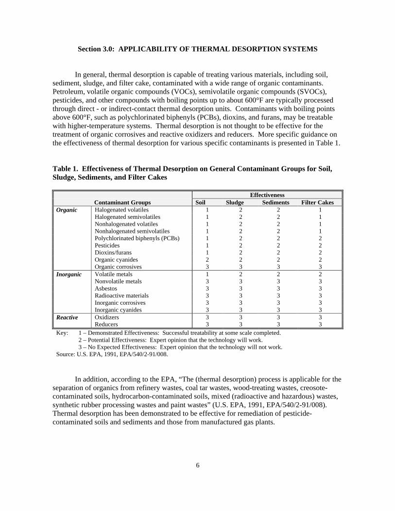
In general, thermal desorption is capable of treating various materials, including soil,sediment, sludge, and filter cake, contaminated with a wide range of organic contaminants.Petroleum, volatile organic compounds (VOCs), semivolatile organic compounds (SVOCs),pesticides, and other compounds with boiling points up to about 600°F are typically processedthrough direct - or indirect-contact thermal desorption units. Contaminants with boiling pointsabove 600°F, such as polychlorinated biphenyls (PCBs), dioxins, and furans, may be treatablewith higher-temperature systems. Thermal desorption is not thought to be effective for thetreatment of organic corrosives and reactive oxidizers and reducers. More specific guidance onthe effectiveness of thermal desorption for various specific contaminants is presented in Table 1.
Table 1. Effectiveness of Thermal Desorption on General Contaminant Groups for Soil,Sludge, Sediments, and Filter Cakes
EffectivenessContaminant Groups Soil Sludge Sediments Filter Cakes
Organic Halogenated volatiles 1 2 2 1Halogenated semivolatiles 1 2 2 1Nonhalogenated volatiles 1 2 2 1Nonhalogenated semivolatiles 1 2 2 1Polychlorinated biphenyls (PCBs) 1 2 2 2Pesticides 1 2 2 2Dioxins/furans 1 2 2 2Organic cyanides 2 2 2 2Organic corrosives 3 3 3 3
Inorganic Volatile metals 1 2 2 2Nonvolatile metals 3 3 3 3Asbestos 3 3 3 3Radioactive materials 3 3 3 3Inorganic corrosives 3 3 3 3Inorganic cyanides 3 3 3 3
Reactive Oxidizers 3 3 3 3Reducers 3 3 3 3
Key: 1 – Demonstrated Effectiveness: Successful treatability at some scale completed.2 – Potential Effectiveness: Expert opinion that the technology will work.3 – No Expected Effectiveness: Expert opinion that the technology will not work.
Source: U.S. EPA, 1991, EPA/540/2-91/008.
In addition, according to the EPA, “The (thermal desorption) process is applicable for theseparation of organics from refinery wastes, coal tar wastes, wood-treating wastes, creosote-contaminated soils, hydrocarbon-contaminated soils, mixed (radioactive and hazardous) wastes,synthetic rubber processing wastes and paint wastes” (U.S. EPA, 1991, EPA/540/2-91/008).Thermal desorption has been demonstrated to be effective for remediation of pesticide-contaminated soils and sediments and those from manufactured gas plants.
7
Thermal desorption is not effective or intended for the treatment of inorganic wastes suchas metals, although those with relatively low boiling points, such as mercury or lead, may bevaporized at higher operating temperatures. If inorganics such as these are present in the wastefeed in significant quantities, it would be useful to know what quantities of these inorganics maybe vaporized into the off-gas stream and therefore have to be managed in the ensuing off-gastreatment stage of the thermal desorption unit. Organics having higher boiling points, and theportion of the lower-boiling-point inorganics that do not vaporize in the primary stage, may needto be dealt with in terms of allowable total concentration limits or leachability values in thetreated residue. In some cases, stabilization of the residue may become necessary.
Various residuals are always generated as part of the thermal desorption process,regardless of the type. Some of these are nonhazardous whereas others are most certainlyhazardous, including the concentrated, condensed liquid form of the contaminants following thefirst step of the thermal desorption process, for certain types of thermal desorption systems.Other typical residuals from thermal desorption systems are the treated off-gas, spent carbon,condensed water, wastewater (treated or untreated), treated materials, noncontact combustiongases, particulates, filters, and catalysts.
In trying to determine the applicability of thermal desorption to a particular site, the RPMmust consider the nature of the contaminated media. Media that may tend to inhibit heat transferby fouling or plugging may not be candidates for thermal desorption designs that may beadversely affected. Materials contaminated with heavy tars or high-viscosity fluids may fall intothis category.
Contaminated media having large clumped masses or sizable boulders may not bedirectly treatable, due to possible nonuniform or inadequate heat transfer or potential jamming offeed and treated material conveyors. Pretreatment screening and/or size reduction would berequired. For many types of thermal desorption systems, the approximate maximum particlefeed size is about 2 inches, because larger particles may not allow the center area to be heatedsufficiently to volatilize organic contaminants. In addition, large clumped masses or boulderscould cause difficulties with conveyors, augers, drag chains, or other mechanical components.
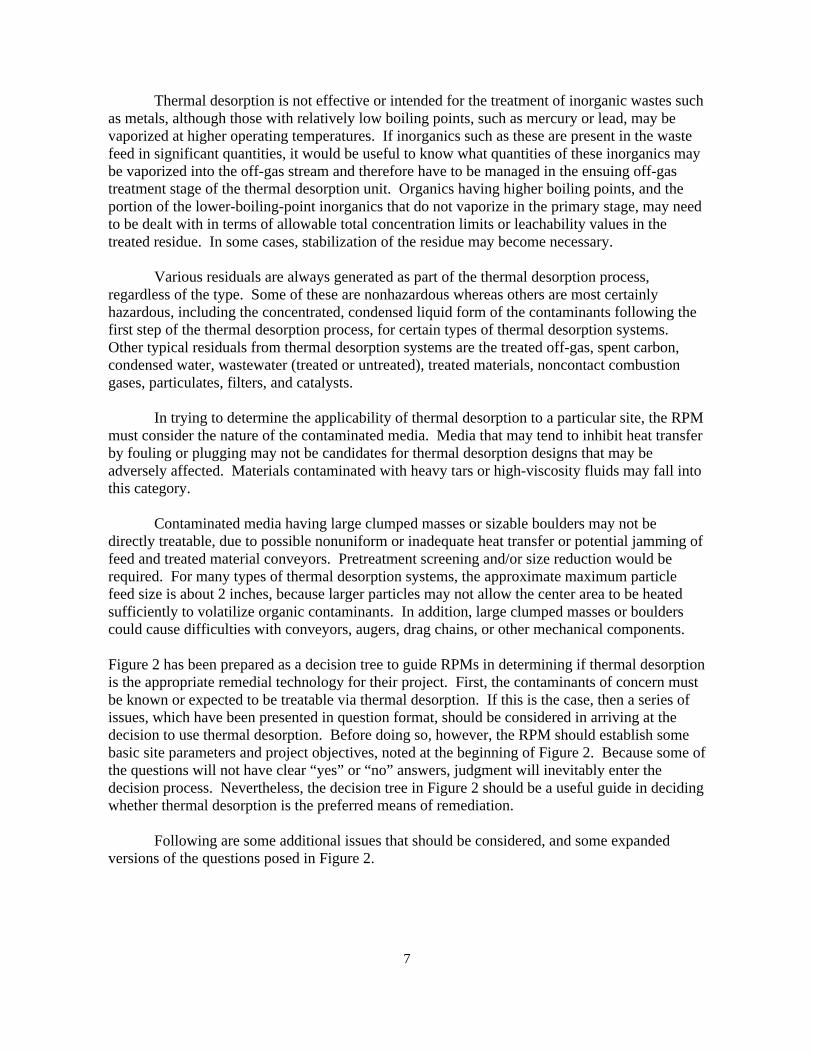
Figure 2 has been prepared as a decision tree to guide RPMs in determining if thermal desorptionis the appropriate remedial technology for their project. First, the contaminants of concern mustbe known or expected to be treatable via thermal desorption. If this is the case, then a series ofissues, which have been presented in question format, should be considered in arriving at thedecision to use thermal desorption. Before doing so, however, the RPM should establish somebasic site parameters and project objectives, noted at the beginning of Figure 2. Because some ofthe questions will not have clear “yes” or “no” answers, judgment will inevitably enter thedecision process. Nevertheless, the decision tree in Figure 2 should be a useful guide in decidingwhether thermal desorption is the preferred means of remediation.
Following are some additional issues that should be considered, and some expandedversions of the questions posed in Figure 2.
8
Figure 2. Thermal Desorption (TD) Technology Selection Decision Tree
9
• Are the concentrations of any inorganics or residual organics low enough that the treatedmaterials can be disposed of readily by backfill, or perhaps with a low-priced subsequenttreatment step such as stabilization?
• Is there a time constraint? If yes, a large-scale thermal desorption unit could be used(although perhaps not cost-effectively) to quickly conduct a project, because relatively hightreatment rates are achievable compared to other potentially useful technologies.
• Is public acceptance of a thermal treatment process a concern, and is the local public likely totolerate the deployment of a thermal desorption unit to the project site?
• Are appropriate utilities available at the site (gas/liquefied petroleum gas [LPG]/fuel oil,electricity, water, etc.) in adequate supply?
• Is sufficient space available at the project for the thermal desorption system, a waste feedpreparation area, a treated residue staging area, and a water treatment system (if applicable)?
• Will the cognizant regulatory agencies accept thermal desorption as a viable means ofremediation, as differentiated from incineration?
• Does the cost of thermal desorption, based on typical rates for comparable size projects, seemacceptable?
• The 5,000-cubic-yard (CY) volume decision point for focusing on the use of in situ thermaldesorption technologies, the HAVE system, and off-site options is a typical value. The actualvolume of contaminated material at which these options are more economical is site-specific anddepends on many factors, such as local labor costs, proximity of the project to off-site disposalfacilities, regulatory agency acceptance of thermal desorption versus incineration, and so on. Insome instances, the volume decision point may be as high as 10,000 CY.
10
Section 4.0: OVERVIEW OF VARIOUS TYPES OFTHERMAL DESORPTION SYSTEMS
Today, a variety of thermal desorption systems are used as part of numerous governmentand private remediation projects. As stated earlier, all thermal desorption technologies consist oftwo steps: (1) heating the contaminated material to volatize the organic contaminants, and (2)treating the exhaust gas stream to prevent emissions of the volatized contaminants to theatmosphere. The systems are differentiated from each other by the methods used to transfer heat tothe contaminated materials, and by the gas treatment system used to treat the off-gases. Heat can beapplied directly by radiation from a combustion flame and/or by convection from direct contact withthe combustion gases. Systems employing this type of heat transfer are referred to as direct-contactor direct-fired thermal desorption systems. Heat can also be applied indirectly by transferring theheat from the source (e.g., combustion or hot oil) through a physical barrier that separates the heatsource from the contaminated materials, such as a steel wall. Systems employing this type of heattransfer are referred to as indirect-contact or indirect-fired thermal desorption systems.
Thermal desorption systems can be further divided into two broad categories: continuous-feed and batch-feed types. Continuous-feed systems are ex situ processes, meaning that thecontaminated material must be excavated from its original location, followed by some degree ofmaterial handling, and then fed to the treatment unit. Continuous-feed thermal desorptionsystems can use direct-contact (direct-fired) equipment or indirect-contact (indirect-fired)equipment, as described previously. The following are representative types of continuous-feedthermal desorption technologies:
• Direct-contact thermal desorption—rotary dryer• Indirect-contact thermal desorption—rotary dryer and thermal screw conveyor.
Batch-feed systems can be either ex situ or in situ, the latter meaning that the material istreated in place, without the need for and expense of excavating or dredging it before treatment.As with all thermal desorption systems, the off-gases from in situ systems must be treated priorto discharge to the atmosphere. The following are representative types of batch-feed thermaldesorption technologies:
• Ex situ—heated oven and hot-air vapor extraction (HAVE)• In situ—thermal blanket, thermal well, “enhanced” soil vapor extraction.
4.1 Continuous-Feed Systems — Direct Contact. Direct-contact thermal desorptionsystems have been developed in at least three stages over the years. Throughputs of as high as160 tons/hr have been demonstrated.
The first-generation direct-contact thermal desorption systems employ, as principal processelements, a rotary dryer, a fabric filter baghouse, and an afterburner, in that sequence. Thesesystems are very economical to purchase and operate, but are limited in that they are useful only

11
for low-boiling-point (below about 500°F to 600°F), nonchlorinated contaminants. The material isgenerally treated to 300°F to 400°F. Figure 3 illustrates a typical system process
AtmosphereFeed <450o F
Treated Material(300o - 400oF)
FOR LOW-BOILING-POINT, NONCHLORINATED CONTAMINANTS
RotaryDryer
Fabric Filter(Baghouse)
Afterburner(1,400 - 1,800oF
Figure 3. First Generation—Direct-Contact Thermal Desorption Process
schematic. Due to the location of the baghouse, the system is not capable of handling high-boiling-point organics as the high-molecular-weight compounds will condense and increase the pressuredrop across the bags.
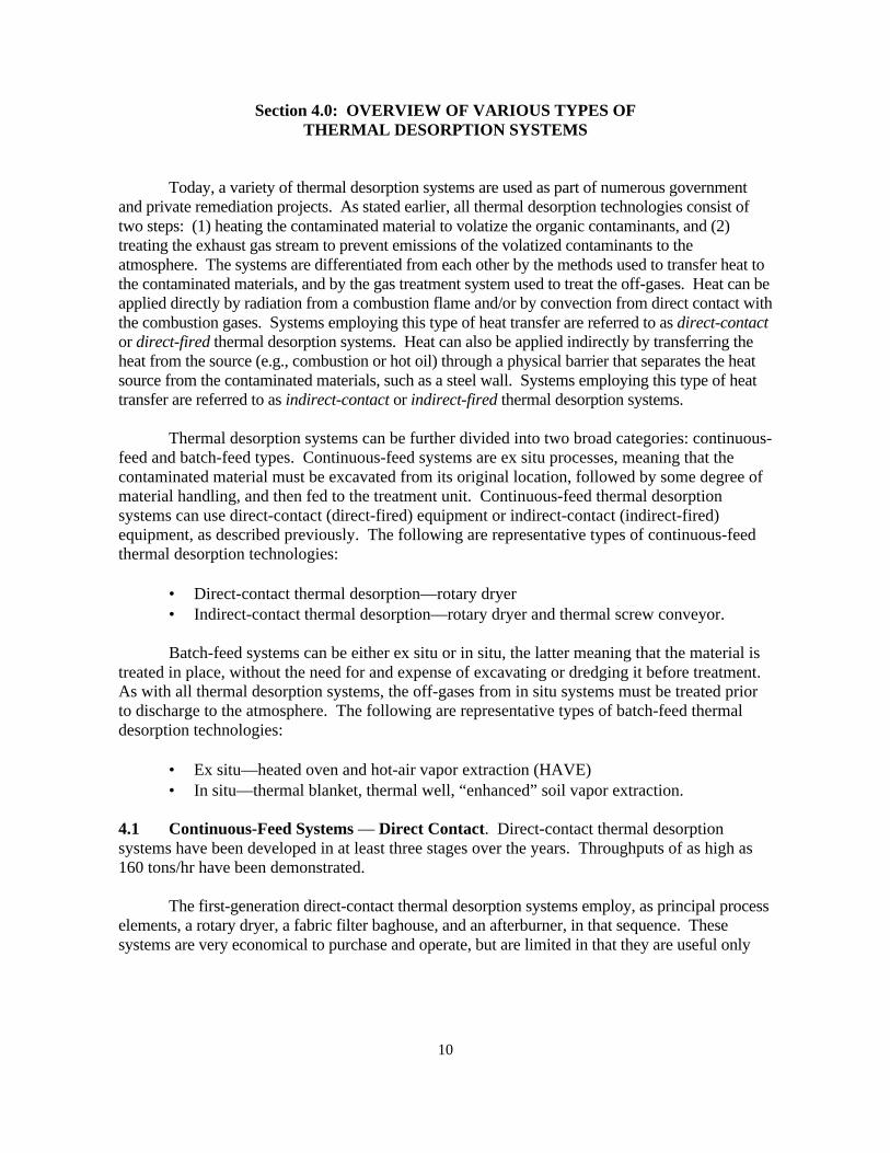
The second generation of direct-contact thermal desorption systems was developed forhigher-boiling-point, nonchlorinated contaminants (above 600°F). These systems usuallyemploy a rotary dryer, an afterburner, a gas cooler, and a baghouse as the principal processelements, in that sequence. This system can treat high-boiling-point organics because the dryercan heat the contaminated materials to higher temperatures, which results in higher off-gastemperatures, without damaging the baghouse. Positioning the baghouse at the end of thetreatment train enables it to remove particulates in the off-gas while maintaining temperatures inthe gas stream in the 450 to 500°F range. In addition, vaporized organics are destroyed in theafterburner, so the potential for condensation of high-molecular-weight organics in the baghouseis eliminated. These thermal desorption systems are normally capable of heating the treatedresidue to a range of about 500°F to 1,200°F. Figure 4 illustrates a typical system processschematic. These systems are now capable of treating materials contaminated with heavier oils,but are still limited to nonchlorinated compounds because they have no means of controlling thehydrochloric acid emissions resulting from the combustion of chlorinated compounds.
12
AtmosphereSoilFeed
<450o F
Treated Soil(500o - 1,200oF)
FOR HIGHER-BOILING-POINT, NONCHLORINATED CONTAMINANTS
RotaryDryer
Afterburner(1,400o - 1,800oF)
GasCooler
Fabric Filter(Baghouse)
Figure 4. Second Generation—Direct-Contact Thermal Desorption Process
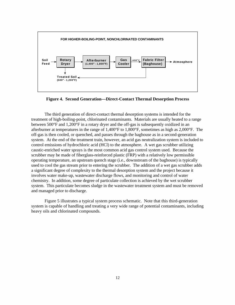
The third generation of direct-contact thermal desorption systems is intended for thetreatment of high-boiling-point, chlorinated contaminants. Materials are usually heated to a rangebetween 500°F and 1,200°F in a rotary dryer and the off-gas is subsequently oxidized in anafterburner at temperatures in the range of 1,400°F to 1,800°F, sometimes as high as 2,000°F. Theoff-gas is then cooled, or quenched, and passes through the baghouse as in a second-generationsystem. At the end of the treatment train, however, an acid gas neutralization system is included tocontrol emissions of hydrochloric acid (HCl) to the atmosphere. A wet gas scrubber utilizingcaustic-enriched water sprays is the most common acid gas control system used. Because thescrubber may be made of fiberglass-reinforced plastic (FRP) with a relatively low permissibleoperating temperature, an upstream quench stage (i.e., downstream of the baghouse) is typicallyused to cool the gas stream prior to entering the scrubber. The addition of a wet gas scrubber addsa significant degree of complexity to the thermal desorption system and the project because itinvolves water make-up, wastewater discharge flows, and monitoring and control of waterchemistry. In addition, some degree of particulate collection is achieved by the wet scrubbersystem. This particulate becomes sludge in the wastewater treatment system and must be removedand managed prior to discharge.
Figure 5 illustrates a typical system process schematic. Note that this third-generationsystem is capable of handling and treating a very wide range of potential contaminants, includingheavy oils and chlorinated compounds.
13
AtmosphereFeed
<450o F
Treated Material(500 - 1,200oF)
Wastewater Treatment
and Discharge
FOR HIGH-BOILING-POINT, CHLORINATED CONTAMINANTS
RotaryDryer
Afterburner(1,400 - 1,800oF)
GasCooler
Fabric Filter(Baghouse)
WetScrubber
Figure 5. Third Generation—Direct-Contact Thermal Desorption Process
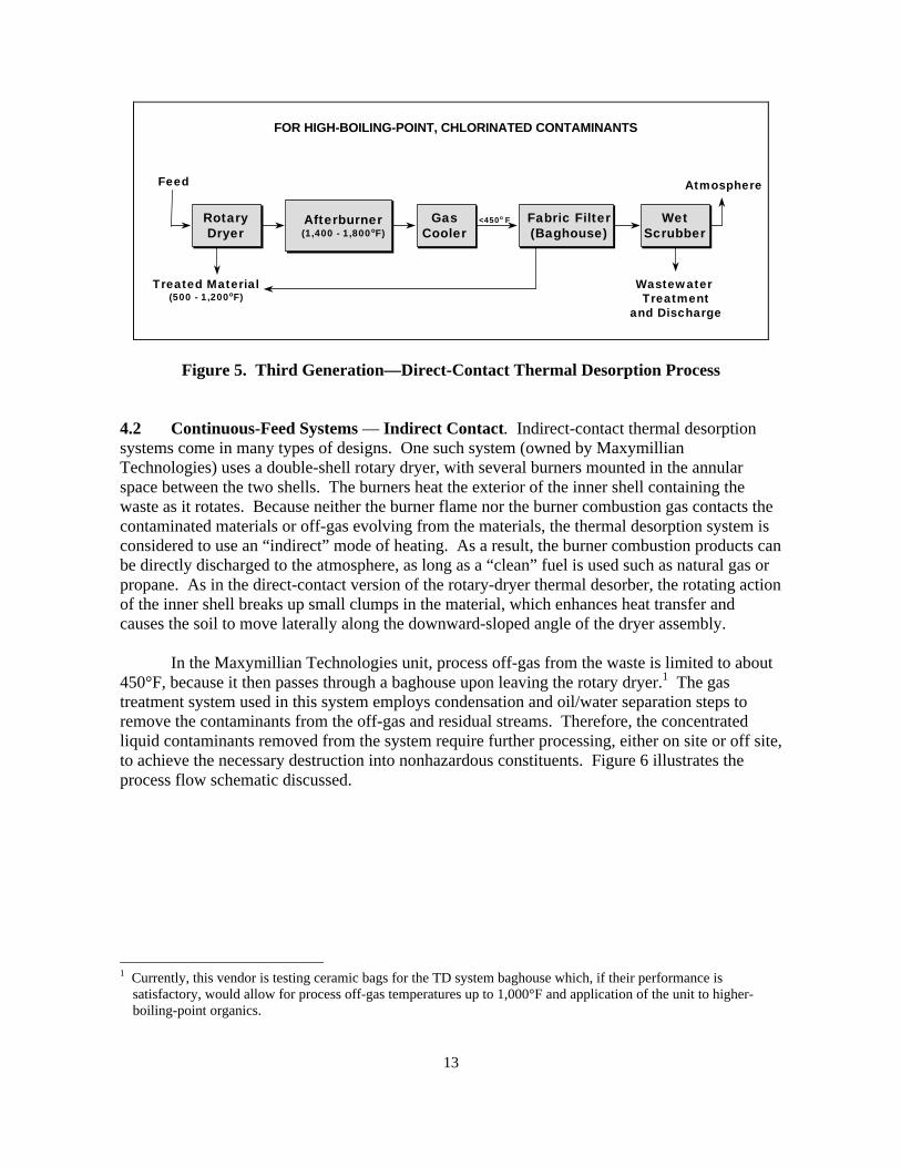
4.2 Continuous-Feed Systems — Indirect Contact. Indirect-contact thermal desorptionsystems come in many types of designs. One such system (owned by MaxymillianTechnologies) uses a double-shell rotary dryer, with several burners mounted in the annularspace between the two shells. The burners heat the exterior of the inner shell containing thewaste as it rotates. Because neither the burner flame nor the burner combustion gas contacts thecontaminated materials or off-gas evolving from the materials, the thermal desorption system isconsidered to use an “indirect” mode of heating. As a result, the burner combustion products canbe directly discharged to the atmosphere, as long as a “clean” fuel is used such as natural gas orpropane. As in the direct-contact version of the rotary-dryer thermal desorber, the rotating actionof the inner shell breaks up small clumps in the material, which enhances heat transfer andcauses the soil to move laterally along the downward-sloped angle of the dryer assembly.
In the Maxymillian Technologies unit, process off-gas from the waste is limited to about450°F, because it then passes through a baghouse upon leaving the rotary dryer.1 The gastreatment system used in this system employs condensation and oil/water separation steps toremove the contaminants from the off-gas and residual streams. Therefore, the concentratedliquid contaminants removed from the system require further processing, either on site or off site,to achieve the necessary destruction into nonhazardous constituents. Figure 6 illustrates theprocess flow schematic discussed.
1 Currently, this vendor is testing ceramic bags for the TD system baghouse which, if their performance is
satisfactory, would allow for process off-gas temperatures up to 1,000°F and application of the unit to higher-boiling-point organics.
14
Indirectly HeatedDesorber
Noncontact FurnaceExhaust
Baghouse Condenser
Oil/WaterSeparation
CarbonPreheat
HEPAFilter
Vapor-PhaseCarbon
FuelTreated
Soil
SoilFeed
WastewaterTreatment and
Discharge
Atmosphere
Organic Residueto Treatment(on or off site)
<450°F
Adapted from MaxymillianTechnologies, Pittsfield, MA
Figure 6. Indirect-Contact Rotary Dryer Thermal Desorption Process
This thermal desorption system seems to exemplify what EPA intended when thermaldesorption was conceived. In the first stage, contaminants are desorbed; i.e., they are separatedfrom the material at a relatively low temperature. In the second stage they are condensed into aconcentrated liquid form, suitable for transport off site to a fixed-base “traditional” treatment ordisposal facility, such as a commercial incinerator. The contaminants are not destroyed viathermal oxidation in this type of thermal desorption; instead they are separated from the bulkmaterial for subsequent processing elsewhere. This type of thermal desorption process reducesthe volume of contaminants that require further treatment.
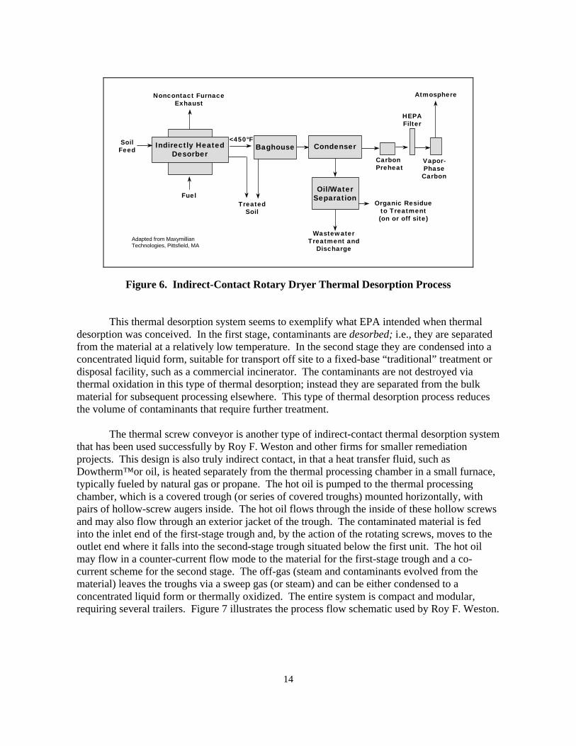
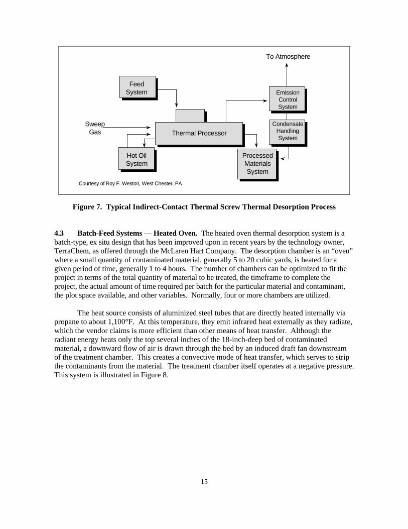
The thermal screw conveyor is another type of indirect-contact thermal desorption systemthat has been used successfully by Roy F. Weston and other firms for smaller remediationprojects. This design is also truly indirect contact, in that a heat transfer fluid, such asDowtherm™or oil, is heated separately from the thermal processing chamber in a small furnace,typically fueled by natural gas or propane. The hot oil is pumped to the thermal processingchamber, which is a covered trough (or series of covered troughs) mounted horizontally, withpairs of hollow-screw augers inside. The hot oil flows through the inside of these hollow screwsand may also flow through an exterior jacket of the trough. The contaminated material is fedinto the inlet end of the first-stage trough and, by the action of the rotating screws, moves to theoutlet end where it falls into the second-stage trough situated below the first unit. The hot oilmay flow in a counter-current flow mode to the material for the first-stage trough and a co-current scheme for the second stage. The off-gas (steam and contaminants evolved from thematerial) leaves the troughs via a sweep gas (or steam) and can be either condensed to aconcentrated liquid form or thermally oxidized. The entire system is compact and modular,requiring several trailers. Figure 7 illustrates the process flow schematic used by Roy F. Weston.
15
Courtesy of Roy F. Weston, West Chester, PA
SweepGas
To Atmosphere
FeedSystem
Thermal Processor
Hot OilSystem
ProcessedMaterialsSystem
CondensateHandlingSystem
EmissionControlSystem
Figure 7. Typical Indirect-Contact Thermal Screw Thermal Desorption Process
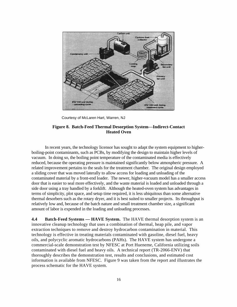
4.3 Batch-Feed Systems — Heated Oven. The heated oven thermal desorption system is abatch-type, ex situ design that has been improved upon in recent years by the technology owner,TerraChem, as offered through the McLaren Hart Company. The desorption chamber is an “oven”where a small quantity of contaminated material, generally 5 to 20 cubic yards, is heated for agiven period of time, generally 1 to 4 hours. The number of chambers can be optimized to fit theproject in terms of the total quantity of material to be treated, the timeframe to complete theproject, the actual amount of time required per batch for the particular material and contaminant,the plot space available, and other variables. Normally, four or more chambers are utilized.
The heat source consists of aluminized steel tubes that are directly heated internally viapropane to about 1,100°F. At this temperature, they emit infrared heat externally as they radiate,which the vendor claims is more efficient than other means of heat transfer. Although theradiant energy heats only the top several inches of the 18-inch-deep bed of contaminatedmaterial, a downward flow of air is drawn through the bed by an induced draft fan downstreamof the treatment chamber. This creates a convective mode of heat transfer, which serves to stripthe contaminants from the material. The treatment chamber itself operates at a negative pressure.This system is illustrated in Figure 8.
16
Courtesy of McLaren Hart, Warren, NJ
Figure 8. Batch-Feed Thermal Desorption System—Indirect-ContactHeated Oven
In recent years, the technology licensor has sought to adapt the system equipment to higher-boiling-point contaminants, such as PCBs, by modifying the design to maintain higher levels ofvacuum. In doing so, the boiling point temperature of the contaminated media is effectivelyreduced, because the operating pressure is maintained significantly below atmospheric pressure. Arelated improvement pertains to the seals for the treatment chamber. The original design employeda sliding cover that was moved laterally to allow access for loading and unloading of thecontaminated material by a front-end loader. The newer, higher-vacuum model has a smaller accessdoor that is easier to seal more effectively, and the waste material is loaded and unloaded through aside door using a tray handled by a forklift. Although the heated-oven system has advantages interms of simplicity, plot space, and setup time required, it is less ubiquitous than some alternativethermal desorbers such as the rotary dryer, and it is best suited to smaller projects. Its throughput isrelatively low and, because of the batch nature and small treatment chamber size, a significantamount of labor is expended in the loading and unloading processes.
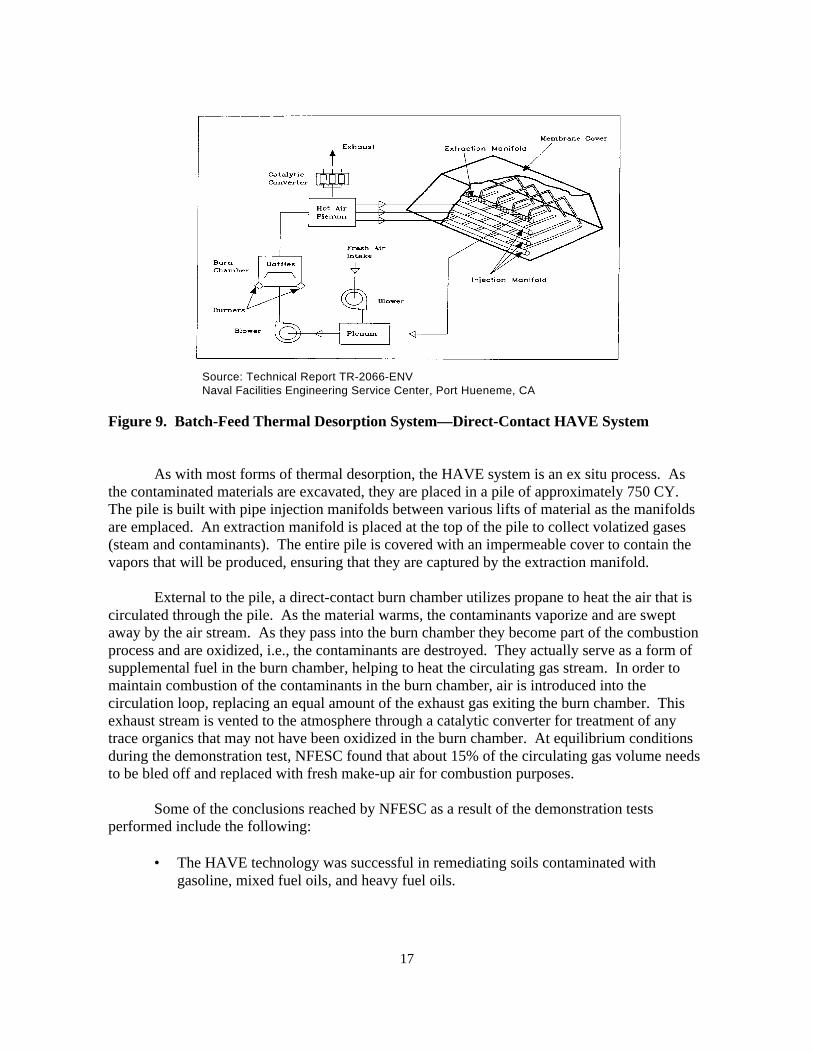
4.4 Batch-Feed Systems — HAVE System. The HAVE thermal desorption system is aninnovative cleanup technology that uses a combination of thermal, heap pile, and vaporextraction techniques to remove and destroy hydrocarbon contamination in material. Thistechnology is effective in treating materials contaminated with gasoline, diesel fuel, heavyoils, and polycyclic aromatic hydrocarbons (PAHs). The HAVE system has undergone acommercial-scale demonstration test by NFESC at Port Hueneme, California utilizing soilscontaminated with diesel fuel and heavy oils. A technical report (TR-2066-ENV) thatthoroughly describes the demonstration test, results and conclusions, and estimated costinformation is available from NFESC. Figure 9 was taken from the report and illustrates theprocess schematic for the HAVE system.
17
Source: Technical Report TR-2066-ENVNaval Facilities Engineering Service Center, Port Hueneme, CA
Figure 9. Batch-Feed Thermal Desorption System—Direct-Contact HAVE System
As with most forms of thermal desorption, the HAVE system is an ex situ process. Asthe contaminated materials are excavated, they are placed in a pile of approximately 750 CY.The pile is built with pipe injection manifolds between various lifts of material as the manifoldsare emplaced. An extraction manifold is placed at the top of the pile to collect volatized gases(steam and contaminants). The entire pile is covered with an impermeable cover to contain thevapors that will be produced, ensuring that they are captured by the extraction manifold.
External to the pile, a direct-contact burn chamber utilizes propane to heat the air that iscirculated through the pile. As the material warms, the contaminants vaporize and are sweptaway by the air stream. As they pass into the burn chamber they become part of the combustionprocess and are oxidized, i.e., the contaminants are destroyed. They actually serve as a form ofsupplemental fuel in the burn chamber, helping to heat the circulating gas stream. In order tomaintain combustion of the contaminants in the burn chamber, air is introduced into thecirculation loop, replacing an equal amount of the exhaust gas exiting the burn chamber. Thisexhaust stream is vented to the atmosphere through a catalytic converter for treatment of anytrace organics that may not have been oxidized in the burn chamber. At equilibrium conditionsduring the demonstration test, NFESC found that about 15% of the circulating gas volume needsto be bled off and replaced with fresh make-up air for combustion purposes.
Some of the conclusions reached by NFESC as a result of the demonstration testsperformed include the following:
• The HAVE technology was successful in remediating soils contaminated withgasoline, mixed fuel oils, and heavy fuel oils.
18
• The HAVE system performed well with soils containing less than 14% moisture and lessthan 20% clay.
• Materials can be heated to average temperatures in the range of 150oF for gasolinecontamination and up to approximately 450oF for heavier fuels and oils.
• The “optimum” size pile was estimated to be approximately 750 CY. A pile this size,containing less than 20% clay, moisture of 12% or less, and TPH concentrations up to5,000 ppm, can be remediated over a period of approximately 18 days. Higherconcentrations require longer treatment times.
Based on the above, it is estimated that the HAVE technology will be applicable toproject sizes ranging from a few hundred cubic yards up to approximately 5,000 CY.
4.5 Batch-Feed Systems — In Situ Systems: Thermal Blanket and Thermal Well. Thethermal blanket and thermal well types of thermal desorption technology are in situ thermaltreatment technologies. At the present time they are proprietary technologies of TerrathermEnvironmental Services, an affiliate of Shell Oil Company. They represent one of the few in situforms of thermal desorption technology that has been demonstrated to work effectively on acommercial scale.
The thermal blanket system utilizes modularized electric heating “blankets” about 8 ft x 20ft that are placed on top of the contaminated ground surface. The blankets can be heated to1,000°C (1,832°F) and, by thermal conduction from direct contact with the contaminated material,are able to vaporize most contaminants down to about 3 ft deep. The blanket module is coveredwith an impermeable membrane having a vacuum-exhaust port. Several modules can be usedsimultaneously by connecting the exhaust ports to a common manifold leading to an induced-draftblower system. As the contaminants are volatized from the materials, they are drawn out of thematerial by the induced-draft blower. Once the contaminants are in the vapor stream, they areoxidized at high temperature in a thermal oxidizer near the treatment area. The gas stream is thencooled to protect the downstream induced-draft blower and passed through a carbon bed thatcollects any trace levels of organics not oxidized prior to release to the atmosphere.
The thermal well system involves an arrangement of electrical immersion heating elementsplaced deep in the ground at about 7 to 10 ft apart. The wells are intended to remediatecontaminated material from about 3 ft below grade to at least the water-table elevation, ifnecessary. The heating elements are raised to more than 1,000°C and, thereby, heat thesurrounding material. Similar to the thermal blanket system, heat transfer for the thermal wellsystem is via conduction only. The wells are installed with an outer perforated sleeve or screen.The top outlets of all of the wells used in a particular application are connected to a commonmanifold. Similarly to the blanket modules, vacuum is drawn on the manifold so that as thecontaminants are desorbed from the material, they are evacuated through the well sleeve/manifoldnetwork and destroyed.
The Terratherm literature states that, in many applications, both the thermal blanket andthe thermal well systems can be used sequentially to allow for remediation coverage from the
19
ground surface down to at least the water-table level. The literature also states that thermal welltechnology is effective in remediating material below the water table, as long as a barrier isinstalled to prevent water infiltration to the well field area. If water flow were not restricted,system performance and efficiency would be reduced by the need to evaporate significantvolumes of groundwater locally.
Terratherm has successfully demonstrated their thermal blanket and thermal welltechnologies at a PCB-contaminated site in upstate New York. As this paper is being written,they are about to conduct another demonstration for the Navy as part of the Mare Island projectfor PCB remediation under the Bay Area Defense Conversion Action Team (BADCAT) Programin California. Information from this effort will be forthcoming from NFESC after completion.
These technologies are interesting because they avoid the need to excavate contaminatedmaterial, thereby eliminating material handling concerns along with the cost of the excavationitself. The thermal blanket and thermal well technologies can be thought of as thermallyenhanced soil vapor extraction (SVE). Therefore, as with SVE, the geotechnical characteristics(such as permeability) of the ground to be treated must be amenable for these techologies to befeasible. They are also more quiet and less obtrusive than many other thermal desorptiontechnologies. At the present time, however, their treatment costs are higher than costs for moreestablished technologies (refer to Section 6.0). Their costs may become more competitive In thefuture as the technologies develop and become more popular.
4.6 Batch-Feed Systems — In Situ Systems: Enhanced Soil Vapor Extraction. EnhancedSVE utilizes a series of wells installed in the contaminated areas. One series of wells is used toinject hot air or steam into the ground to heat the materials and contaminants. The rest of the wellshave a vacuum applied to them to extract the volatized contaminants from the materials. The gasesextracted from the wells can be treated in the same manner as with other thermal desorptiontechnologies, i.e., through condensation, collection on activated carbon, or combustion.
Three basic factors control the effectiveness of enhanced SVE: (1) the physical and chemicalproperties of the contaminants to be removed, (2) the “in-place” air permeability of the materialsto be treated, and (3) the homogeneity of the materials. Because this technology is wellestablished and documented in various reports and design documents, it will not be addressed inany more detail here.
20
Section 5.0: DESIGN AND PERFORMANCE CHARACTERISTICS
The design and performance of a particular type of thermal desorption unit can usually bepredicted reliably, as long as the nature of the contaminated media to be processed can bedefined and is somewhat consistent. Most of the technologies have been in use for several years,often as outgrowths of other types of industry, so that equipment design parameters are wellestablished. For example, one can readily determine the expected throughput for a rotary dryerbased on the qualities and consistency of the waste to be fed. The waste feed preparation stageof the remediation process, therefore, is vitally important in predicting and ensuring the successof the subsequent thermal treatment step.
Because soils and sediments are inherently variable in their physical and chemicalcharacteristics, the ability to accurately describe these characteristics is critical. Some of theimportant properties of the waste material, and the reasons for considering the properties, are asfollows:
• Particle Size Distribution. This is one of several indicators of potential carryover offines in rotary dryer systems, which can be problematic. The breakpoint between coarse-grained material and fine-grained material is generally defined by the percentage ofparticles greater or smaller than a No. 200 sieve (0.075 mm). Fine material consisting ofsilts and clays is likely to become “carried over” in a rotary-dryer system, meaning that itwill exit the dryer entrained in the gas stream instead of with the treated residue, which ispreferred. The undesirable carryover can overload the downstream gas-handling andtreatment equipment, causing pressure profile and buildup problems, and possiblyexceeding the ability of the baghouse or cyclone and conveyor equipment to recover itand rejoin the fines with the treated residue. In addition to particle size distribution,several other design or operating characteristics of the thermal desorption systeminfluence particle carryover.
• Composition (Degree of Sand, Clay, Silt, Rock, etc.). For heat transfer andmechanical handling considerations, it is useful to review information on composition. Ingeneral, coarse, unconsolidated materials, such as sands and fine gravels, are more readilytreated by thermal desorption, because they tend not to agglomerate into larger particles.Hence, more of the surface area of the particles is exposed to the heating medium.Agglomerated particles are somewhat self-insulating, which may interfere with thoroughheat and mass transfer, and hence, desorption of the contaminants. A similar, undesirablephenomenon would occur with the processing of large rocks (in addition to material-handling difficulties for conveyors and augers). Consequently, the maximum particle size istypically limited to 2 inches for materials fed to rotary-dryer systems. Clays may cause poorthermal desorption performance because they tend to increase agglomeration and caking andthereby inhibit heat and mass transfer.
• Bulk Density. This property is of interest for ex situ processes, as a conversionbetween tons and CY. For vendors to determine operating costs, the actual weight of thematerial to be treated is more important than the volume, in order to develop heat and massbalance relationships. However, volume tends to be used as a basis for payment because it
21
can be accurately measured in place by survey, without consideration of whether a weighscale was calibrated properly or sufficiently, and without the need to subtract the weight offeed material that may have been reprocessed and hence crossed the feed scale twice.
• Permeability. Knowledge of this property is particularly important for thoseprocesses (such as the HAVE system) involving the induction of vaporized contaminantsthrough the material.
• Plasticity. This property indicates the degree of material deformation withoutshearing. Plastic materials, such as clays, can clump and form larger particles with lowsurface area to volume ratios, possibly resulting in inadequate desorption in the interiorcore. They can also foul heat transfer surfaces, such as the exterior of a hot oil screwauger, decreasing thermal efficiency. Plastic materials may present material handlingproblems both before and during thermal desorption processing due to sticking andpossibly jamming effects.
• In-Place Homogeneity. This characteristic is important for in situ thermaldesorption treatments, such as the thermal well and thermal blanket designs. Ideally, thesubsurface should be quite homogeneous, so that the underground vapor flow, heattransfer, and remediation are uniform. Large boulders, bedrock irregularities, sandlenses, or impermeable layers (such as clay) might adversely affect the consistency of thetreatment process.
• Moisture Content. The degree of moisture can adversely affect operating costs becausemoisture is evaporated in the treatment process, requiring fuel. Moreover, the added volumeof water vapor in the process off-gas can result in a lower waste throughput, because thewater vapor must be handled by the downstream treatment equipment along with thebalance of the off-gas and the desorbed contaminants. The lower processing throughput isattributable to (1) higher gas flows, resulting in greater pressure drops through the thermaldesorption system; and (2) thermal input limitations (i.e., because some of the heating inputis used to vaporize the water in the waste feed, it may become necessary to reduce the feedrate so that the waste which is fed can be heated adequately to achieve satisfactorydesorption). For most rotary thermal desorption systems, up to approximately 20% (byweight) moisture content can be present in the feed with no significant effect on operationalcost and/or throughput. Beyond 20% moisture content, it may be desirable to investigatewhether the moisture content could be lowered more economically in the waste feedpreparation process rather than in the thermal treatment process itself.
On the other hand, it should also be pointed out that some thermal desorption systemsperform more effectively with a certain minimum amount of moisture in the feedmaterial. The HAVE system is one such example. This may be due to the enhanced heattransfer and thermal desorption of the contaminants resulting from the stripping action ofthe vaporized water (i.e., by steam). Additionally, some minimum amount of moisture isdesirable in the waste feed to mitigate dusting problems during material-handlingoperations.
22
In conclusion, between 10 and 20% (by weight) moisture content in the waste feed wouldbe optimal in general.
• Heat Content. Some thermal desorption units are designed with a maximum thermalrelease that they can accommodate, including that from the waste feed material. Forcontaminated materials of low concentration; however, this is not usually a concern becausea relatively small heat release in the thermal desorber is derived from the waste, and nearlyall heat is obtained from combustion of the auxiliary fuel.
• Contaminant Type, Concentration, and Distribution. With this information,material excavation plans can be determined to allow for blending and some degree of“normalizing” of the waste to achieve a more consistent feed to the thermal desorber,enabling it to operate more predictably.
• Halogen Content. Consideration must be given relative to allowable emission levelsto determine whether acid gas neutralization equipment, such as a scrubber, will berequired. One also needs to carefully consider the materials used for construction tominimize corrosion problems when the waste contains halogenated compounds.
• Metals Concentrations. Although it is difficult to predict the amount of metals thatwill be retained in the treated material versus how much will be carried over into the gasstream (perhaps eventually accumulating in the scrubber water), other regulatory issuesmay arise. For example, if the total or leachable concentrations exceed regulatory limits,backfilling may not be an option unless further treatment is performed.
• Alkali Salt Content. This property is used to anticipate whether fusing or “slagging”of the treated residue in rotary-dryer systems is likely, which could present materialhandling and other problems. It is also used to predict potential slagging problems in theafterburner, when utilized.
Considering all of the various thermal desorption technologies described above, oneshould recognize that performance varies by the type of unit, the site characteristics, and theparticular contaminants. In general, however, all units can meet regulatory criteria althoughdifficulty may arise in determining which regulatory criteria apply. Batch-type thermaldesorption systems generally require more processing time and hence are more suited to smallerprojects. Direct-contact units generally are more efficient and are able to provide significantlylower (typically nondetectable) residual concentrations of contaminants.
More detailed information on typical relative design and performance characteristics forthe various thermal desorption systems discussed is included in the Thermal DesorptionApplication Guide available from NFESC (TR-2090-ENV).
23
Section 6.0: COST INFORMATION
Just as the performance of different thermal desorbers varies by type, site characteristics,and the particular contaminants, so does the cost. Some thermal desorbers are more efficient interms of operating costs (i.e., utility costs), maintenance requirements, and required staffinglevels.
6.1 Thermal Desorption Cost Information. The capital cost of different thermal desorbers canalso be significantly different from unit to unit. In addition, differences in accounting practices fromvendor to vendor (i.e., depreciation techniques, whether the equipment still has any book value to theowner firm, etc.), will impact the capital cost recovery element of the overall treatment cost for agiven thermal desorber.
The degree to which a thermal desorption system is appropriately sized, in terms of itsthroughput for a particular project size, affects treatment cost. For example, a unit that is too smallfor a project having a large amount of material to be treated will be operated at the site for anextraordinarily long period of time. Although the capital cost recovery element may be low forthis unit because it was purchased cheaply, the extended schedule will cause the overall projectcost to be excessive, as the ongoing, time-dependent costs of staffing, trailers, etc., will continue tomount. On the other hand, the deployment of an thermal desorption unit that is too large in termsof capacity for a small-quantity project will be financially inefficient because there is not enoughwaste volume to provide a profit margin to offset the greater capital cost recovery charges.Vendors who have units that are too big will not bid on a small project because they know theycannot be competitive, and vice versa.
It is important that the distinction between the “unit treatment cost” for thermaldesorption and the total project cost, in terms of the overall cost divided by the number of tons orcubic yards of material treated, be fully understood. Often, values cited from the literature oreven provided by vendor representatives themselves can be misleading in that they representonly the unit treatment cost. The recipient of the information may incorrectly believe that it isthe full cost for which he/she could expect to remediate a site of a certain tonnage or yardage.
In addition to the unit treatment cost itself, the thermal desorption total project cost caninclude the following:
• Project planning• Project work plans and submittals• Regulatory issues and permitting• Site layout, preparation, mobilization and demobilization• System startup and performance testing• Contaminated material excavation, material handling, and backfilling• Sampling and analysis (contaminated material, air, and water)• Site restoration.
24
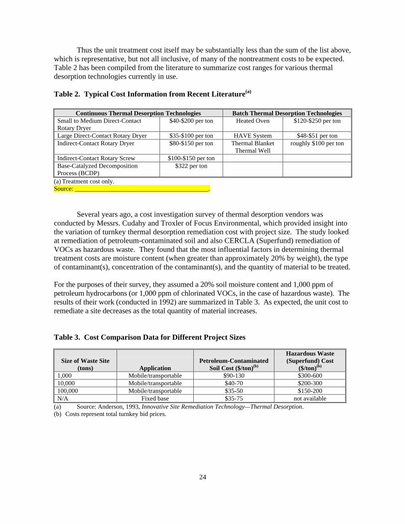
Thus the unit treatment cost itself may be substantially less than the sum of the list above,which is representative, but not all inclusive, of many of the nontreatment costs to be expected.Table 2 has been compiled from the literature to summarize cost ranges for various thermaldesorption technologies currently in use.
Table 2. Typical Cost Information from Recent Literature(a)
Continuous Thermal Desorption Technologies Batch Thermal Desorption TechnologiesSmall to Medium Direct-ContactRotary Dryer
$40-$200 per ton Heated Oven $120-$250 per ton
Large Direct-Contact Rotary Dryer $35-$100 per ton HAVE System $48-$51 per tonIndirect-Contact Rotary Dryer $80-$150 per ton Thermal Blanket
Thermal Wellroughly $100 per ton
Indirect-Contact Rotary Screw $100-$150 per tonBase-Catalyzed DecompositionProcess (BCDP)
$322 per ton
(a) Treatment cost only.Source: __________________________________________.
Several years ago, a cost investigation survey of thermal desorption vendors wasconducted by Messrs. Cudahy and Troxler of Focus Environmental, which provided insight intothe variation of turnkey thermal desorption remediation cost with project size. The study lookedat remediation of petroleum-contaminated soil and also CERCLA (Superfund) remediation ofVOCs as hazardous waste. They found that the most influential factors in determining thermaltreatment costs are moisture content (when greater than approximately 20% by weight), the typeof contaminant(s), concentration of the contaminant(s), and the quantity of material to be treated.
For the purposes of their survey, they assumed a 20% soil moisture content and 1,000 ppm ofpetroleum hydrocarbons (or 1,000 ppm of chlorinated VOCs, in the case of hazardous waste). Theresults of their work (conducted in 1992) are summarized in Table 3. As expected, the unit cost toremediate a site decreases as the total quantity of material increases.
Table 3. Cost Comparison Data for Different Project Sizes
Size of Waste Site(tons) Application
Petroleum-ContaminatedSoil Cost ($/ton)(b)
Hazardous Waste(Superfund) Cost
($/ton)(b)
1,000 Mobile/transportable $90-130 $300-60010,000 Mobile/transportable $40-70 $200-300100,000 Mobile/transportable $35-50 $150-200N/A Fixed base $35-75 not available
(a) Source: Anderson, 1993, Innovative Site Remediation Technology—Thermal Desorption.(b) Costs represent total turnkey bid prices.
25
Also, the costs to remediate hazardous waste, such as at a Superfund site, are much higher than asimple cleanup of petroleum-contaminated soil. As a point of comparative reference, Cudahy andTroxler included pricing for the case of off-site treatment at a fixed-base thermal facility as analternative to bringing a mobile thermal desorption system to the project site.
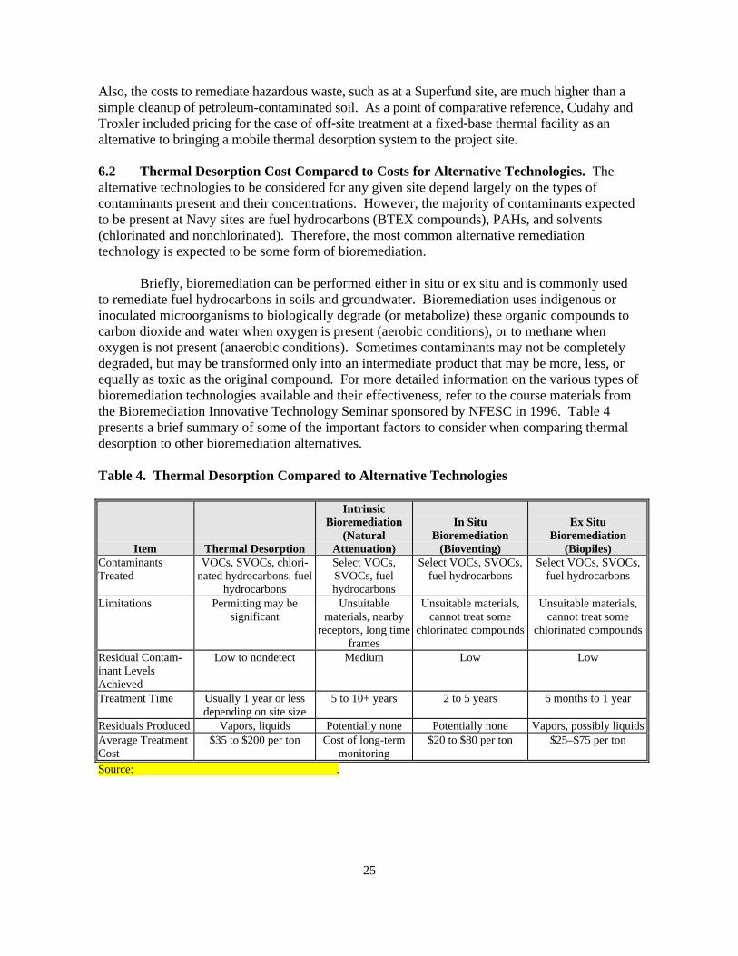
6.2 Thermal Desorption Cost Compared to Costs for Alternative Technologies. Thealternative technologies to be considered for any given site depend largely on the types ofcontaminants present and their concentrations. However, the majority of contaminants expectedto be present at Navy sites are fuel hydrocarbons (BTEX compounds), PAHs, and solvents(chlorinated and nonchlorinated). Therefore, the most common alternative remediationtechnology is expected to be some form of bioremediation.
Briefly, bioremediation can be performed either in situ or ex situ and is commonly usedto remediate fuel hydrocarbons in soils and groundwater. Bioremediation uses indigenous orinoculated microorganisms to biologically degrade (or metabolize) these organic compounds tocarbon dioxide and water when oxygen is present (aerobic conditions), or to methane whenoxygen is not present (anaerobic conditions). Sometimes contaminants may not be completelydegraded, but may be transformed only into an intermediate product that may be more, less, orequally as toxic as the original compound. For more detailed information on the various types ofbioremediation technologies available and their effectiveness, refer to the course materials fromthe Bioremediation Innovative Technology Seminar sponsored by NFESC in 1996. Table 4presents a brief summary of some of the important factors to consider when comparing thermaldesorption to other bioremediation alternatives.
Table 4. Thermal Desorption Compared to Alternative Technologies
Item Thermal Desorption
IntrinsicBioremediation
(NaturalAttenuation)
In SituBioremediation
(Bioventing)
Ex SituBioremediation
(Biopiles)ContaminantsTreated
VOCs, SVOCs, chlori-nated hydrocarbons, fuel
hydrocarbons
Select VOCs,SVOCs, fuelhydrocarbons
Select VOCs, SVOCs,fuel hydrocarbons
Select VOCs, SVOCs,fuel hydrocarbons
Limitations Permitting may besignificant
Unsuitablematerials, nearby
receptors, long timeframes
Unsuitable materials,cannot treat some
chlorinated compounds
Unsuitable materials,cannot treat some
chlorinated compounds
Residual Contam-inant LevelsAchieved
Low to nondetect Medium Low Low
Treatment Time Usually 1 year or lessdepending on site size
5 to 10+ years 2 to 5 years 6 months to 1 year
Residuals Produced Vapors, liquids Potentially none Potentially none Vapors, possibly liquidsAverage TreatmentCost
$35 to $200 per ton Cost of long-termmonitoring
$20 to $80 per ton $25–$75 per ton
Source: __________________________________.
26
Section 7.0: SUMMARY
There are a variety of thermal desorption systems available to suit almost any project.Among them are systems employing rotary dryers (both direct- and indirect-contact), thermalscrew conveyors, heated ovens, and HAVE. In situ systems employing termal blankets andthermal wells are also available. Once the site and the contaminants have been characterized, theappropriate remediation approach and technology can be selected. Whether thermal desorptionor some other technology is used will depend on site-specific criteria, such as the type ofcontamination, the site characteristics, regulatory agency acceptance, and the quantity ofcontaminated materials.
Once the determination has been made that thermal treatment is the appropriate remedy for asite, and the regulatory agencies have agreed that thermal desorption is acceptable, thecompetitive marketplace will determine the correct size, type, cost, and other considerations.Technical specifications for thermal treatment project solicitations are usually performanceoriented rather than providing all of the detailed design information necessary to conduct thework. They generally describe the nature of the problem (how many cubic yards or tons ofmaterial to be treated, the contaminants of concern, other chemical and physical characteristics,etc.), the treatment standards to be achieved, and the timeframe allowed. The marketplace willthen determine the most competitive technology for each site.
From this, experienced vendors/contractors will assess whether they have the correct equipmentto do the work and if they are resourceful enough to perform the work efficiently. The details oftheir approach and technology will be described in their technical and cost proposals. Thesolicitor’s task is then to determine which offeror provides the best value for his/her projectoverall, in terms of a balance between cost, technical approach, schedule, qualifications of keypersonnel, and past experience of the offeror’s firm. Note that the expression “best value” hasbeen used intentionally because selection of the lowest price bidder is not always the bestalternative.
For more information on how these technologies are designed and on their costs, applicability tovarious projects, and how to implement them, please refer to the Thermal DesorptionApplication Guide, available from NFESC (TR-2090-ENV).
Thermal desorption can be performed at both low and high temperatures. In general, low-temperature thermal desorption involves heating the contaminated material to between 300°Fand 600°F, whereas high-temperature thermal desorption processes heat the contaminatedmaterial to between 600°F and 1,200°F.
27
Section 8.0: REFERENCES
Air and Waste Management Association and the Hazardous Waste Action Coalition. 1993.“Innovative Thermal Treatment Technologies—Uses and Applications for Site Remediation.Thermal I: Thermally Enhanced Volatilization.” Live satellite seminar, February 18, 1993 (onvideotape). Distributed by the Air and Waste Management Association.
Anderson, W.C. (Ed.). 1993. Innovative Site Remediation Technology—Thermal Desorption.American Academy of Environmental Engineers.
Committee to Develop On-Site Innovative Technologies. [no date]. Thermal Desorption,Treatment Technology. Western Governors’ Association, Mixed Radioactive/Hazardous WasteWorking Group.
Pal, D., A. P. Mathews, S. Fann, P. Price, E. Lory, and L. Karr. 1996. D/NETDP TechnologyDemonstration Application Analysis Report for Ex-Situ Hot Air Vapor Extraction System. TR-2066-ENV. Report prepared for the Naval Facilities Engineering Service Center, Port Hueneme,CA.
SAIC , see Science Applications International Corporation.
Science Applications International Corporation (SAIC). 1991. Summary of Thermal DesorptionGuide Review Meeting, Cincinnati, OH, June 3-4.
U.S. Environmental Protection Agency. 1991. Engineering Bulletin: Thermal DesorptionTreatment. EPA/540/2-91/008. Superfund. May.
U.S. Environmental Protection Agency. 1994. Draft Guidance for Implementing ThermalDesorption Remedies at Superfund Sites. Memorandum from John J. Smith, Chief Design andConstruction Management Branch. July.
U.S. Environmental Protection Agency. 1994. Vendor Information System for InnovativeTreatment Technologies (VISITT Database), Version 4.0. Office of Solid Waste and EmergencyResponse, Washington, DC.
U.S. Environmental Protection Agency. 1995. Tech Trends: Thermal Desorption at Gas Plants.EPA-542-N-95-003. June, issue no. 20.
U.S. Environmental Protection Agency. 1996. Technology Fact Sheet: A Citizen’s Guide toThermal Desorption. EPA 542-F-96-005. Technology Innovation Office. April.