owner s manual - amazon s3€¦ · explosive material and static electricity aaw y from the...
TRANSCRIPT

OWNER’S MANUAL
GOLF CAR SERIESVERSION: 20112001
COLOR OPTIONS......................................................................................................................................................... 1
VEHICLE FEATURES.................................................................................................................................................. 2
SAFETY INFORMATION ............................................................................................................................................ 4
HDK DECLARATION................................................................................................................................................... 6
IMPORTANT DECALS................................................................................................................................................. 7
Vehicles Serial Number .............................................................................................................................................. 7
Steering Wheel Decals ................................................................................................................................................ 7
CHARGER DECALS..................................................................................................................................................... 8
PRE-OPERATIONS....................................................................................................................................................... 9
OPERATING INSTRUCTION ................................................................................................................................... 11
Brake and Accelerator.............................................................................................................................................. 11
Key switch and indicators ............................................................................................................................................ 13
Dash Board .................................................................................................................................................................... 14
Speedometer .................................................................................................................................................................. 15
Light and Horn Control ............................................................................................................................................... 16
ON BOARD CHARGER.............................................................................................................................................. 17
Charger’s calibration.................................................................................................................................................... 18
How to program a charger without calibration box.................................................................................................. 19
BATTERIES.................................................................................................................................................................. 21
TIRES............................................................................................................................................................................. 22
VEHICLE MODIFICATIONS.................................................................................................................................... 23
Controller................................................................................................................................................................... 23
Motor and Rear Axle ................................................................................................................................................ 23
Headlights .................................................................................................................................................................. 23
TIRES............................................................................................................................................................................. 24
Golf cart accessories option...................................................................................................................................... 24
VEHICLES MAINTENANCE .................................................................................................................................... 25
Tools ........................................................................................................................................................................... 25
Chassis Maintenance .................................................................................................................................................... 27
Electric components maintenance ............................................................................................................................... 29
VEHICLE STORAGE.................................................................................................................................................. 31
SPECIFICATION......................................................................................................................................................... 32
TABLES OF CONTENTS

HDK HAS CUSTOMCOLORS AVAILABLE UPON REQUEST.
SPECIAL COLORS MAY REQUIRE ADDITIONAL COST.
1COLOR OPTIONS
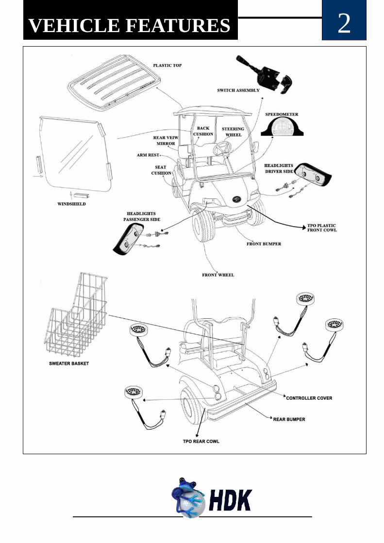
VEHICLE FEATURES 2

3VEHICLE FEATURES
EVERY HDK GOLF CART HASTHE
HOT DIP GALVANIZED CHASSIS.THIS ASSURES YOU “NO RUST
FOR 15 YEARS”.
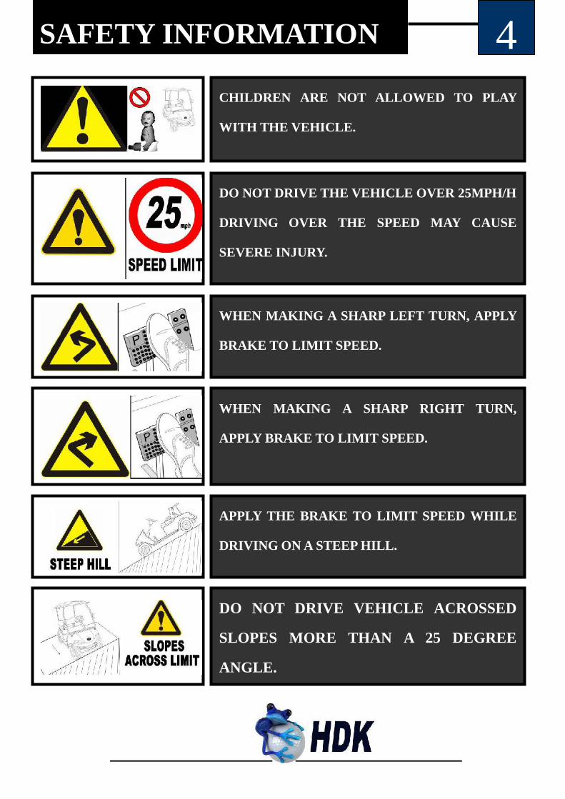
4SAFETY INFORMATION
CHILDREN ARE NOT ALLOWED TO PLAY
WITH THE VEHICLE.
DO NOT DRIVE THE VEHICLE OVER 25MPH/H
DRIVING OVER THE SPEED MAY CAUSE
SEVERE INJURY.
WHEN MAKING A SHARP LEFT TURN, APPLY
BRAKE TO LIMIT SPEED.
WHEN MAKING A SHARP RIGHT TURN,
APPLY BRAKE TO LIMIT SPEED.
APPLY THE BRAKE TO LIMIT SPEED WHILE
DRIVING ON A STEEP HILL.
DO NOT DRIVE VEHICLE ACROSSED
SLOPES MORE THAN A 25 DEGREE
ANGLE.

SAFETY INFORMATION 5
WASH HANDS AFTER HANDLING ANY
BATTERIES.
BATTERY POSTS, TERMINALS AND RELATED
ACCESSORIES CONTAIN LEAD AND LEAD
COMPOUNDS. THESE CHEMICALS ARE KNOWN
FOR CAUSING CANCER AND REPRODUCTIVE
INJURIES.
THE BATTERY WILL GENERATE HYDROGEN GAS
DURING THE CHARING PROCESS. KEEP SMOKE,
EXPLOSIVE MATERIAL AND STATIC
ELECTRICITY AWAY FROM THE BATTERY.
USE AN INSOLATED WRENCH TO OPERATE ON
THE BATTERY IN CASE THE BATTERY SHORT
CIRCUITS. SHORT CIRCUITS GENERATE BIG
CURRENTS THAT WILL CAUSE INJURY.
Grand Safety informationThe owner’s manual contains important safety information. The following decals shouldbe noticed and followed to prevent future injuries.
Indicates the regarding situations- is very important.
Indicates the regarding situations, may causedeath or serious injury.
Indicates the regarding situations- may cause minorinjury or other loss.

6HDK DECLARATION
HDK Vehicles USA, LLC mainly deals with five types of the electric vehicles.
Such as the electric golf car, shuttle bus, utility cart, engineer and
transportation cart, and special electric cars. Among which is the DEL3022G
series of electric golf cars. Our golf car is environmentally friendly and suitable
for use on the course, hotels and other business places. All the key components
are imported from well-known companies. The car has been designed to take
on a new fashion look for electric carts and provides stable performance,
flexible control, and comfortable driving. Our golf car is used as people movers
or utility cars in vacation villages, villa areas, resort hotels, private residential
areas, tourist scenic spots or any other place where this type of golf car is
allowed. The warranty papers are to standardize the after-sale service for
export vehicles, settle the claims efficiently, and improve our after-sale service.
HDK Electric Vehicles has been dedicated in electric vehicles
manufacturing since 2006. Our customers come from all over the world. HDK
Vehicles USA, LLC promises any customer who buys an HDK vehicle, HDK
technicians will be always be ready to fix any problems that may arise. We
provide splendid quality of after sale service.
For more warranty information please read the limited warranty
paperwork that customers receive with a purchase of an HDK vehicle.
For more warranty information please see limited warranty papers, that
customers receive while purchase HDK vehicles.

7IMPORTANT DECALS
Vehicles manufactured by HDK Electric Vehicles,all have vehicle serial numbers on the left side ofthe chassis frame. The first four numbers are themanufacturing year of the vehicle. The other fivenumbers are the vehicle’s serial number given byHDK. All the vehicles are recorded. After thevehicles are sold out of the factory, HDKCorporation will track the vehicles by using thevehicle’s serial number as identity. Serialnumbers are the insurance warranty of HDKCorporation. Customers should aware of theimportance of the vehicle’s serial numbers.
, DO NOT REMOVE while using the vehicles
or in routine maintenance.
Manufacturing yearVehicle’s
serial number
①. Steering wheel②. HDK decal③. Vehicle operatinginstructions decal
①
②
③
*Vehicle’s serial number
*Steering wheel decals
③
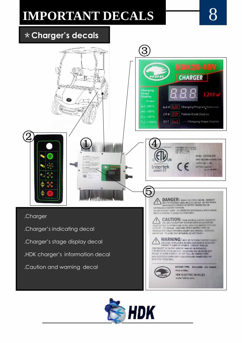
①.Charger
②.Charger’s indicating decal
③.Charger’s stage display decal
④.HDK charger’s information decal
⑤.Caution and warning decal
①②
③
①
④
⑤
IMPORTANT DECALS 8*Charger’s decals

9PRE-OPERATIONS
Before using the vehicle, the batteries should be
fully charged. Estimated charging time should be
more than 10 hours.①
②
③
①
④
Check the brake pedal. When stepped on it
should be flexible and feel firm. When released, it
should return to its original position with
flexibility.
Check the accelerator pedal. When stepped on
and released it should return to its original
position with full flexibility.
Check the signal lights. The brake lights and
turning lights should be in proper working
condition.
Check the tires’ pressure. It should be inflated
until the pressure is around 20~23PSL
(138kpa~159kpa)
Check the reverse beeper. When the direction
selecting switch is set at “REV”, it should beep
consistently.
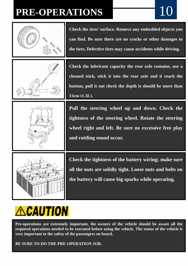
PRE-OPERATIONS 10Check the tires’ surface. Remove any embedded objects you
can find. Be sure there are no cracks or other damages to
the tires. Defective tires may cause accidents while driving.
Check the lubricant capacity the rear axle contains, use a
cleaned stick, stick it into the rear axle and it reach the
bottom, pull it out check the depth is should be more than
13cm (1.3L).
Pull the steering wheel up and down. Check the
tightness of the steering wheel. Rotate the steering
wheel right and left. Be sure no excessive free play
and rattling sound occur.
Check the tightness of the battery wiring; make sure
all the nuts are solidly tight. Loose nuts and bolts on
the battery will cause big sparks while operating.
Pre-operations are extremely important, the owners of the vehicle should be aware all therequired operations needed to be executed before using the vehicle. The status of the vehicle isvery important to the safety of the passengers on board.
BE SURE TO DO THE PRE-OPERATION JOB.

*Brake and Accelerator
① ②
③
※MECHANICAL
OPERATING INSTRUCTION 11
①Use the accelerator pedal to control the vehicle’s speed.
②Use the brake pedal to decrease velocity.
③Use the parking pedal to keep car stationary.
①
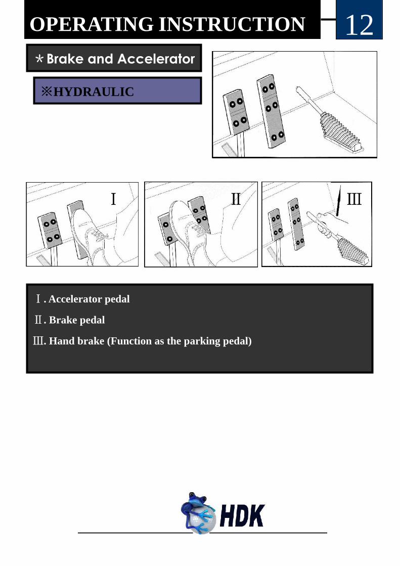
Ⅰ. Accelerator pedal
Ⅱ. Brake pedal
Ⅲ. Hand brake (Function as the parking pedal)
OPERATING INSTRUCTION
Ⅰ Ⅱ Ⅲ
※HYDRAULIC
12*Brake and Accelerator
④ ⑤
⑥
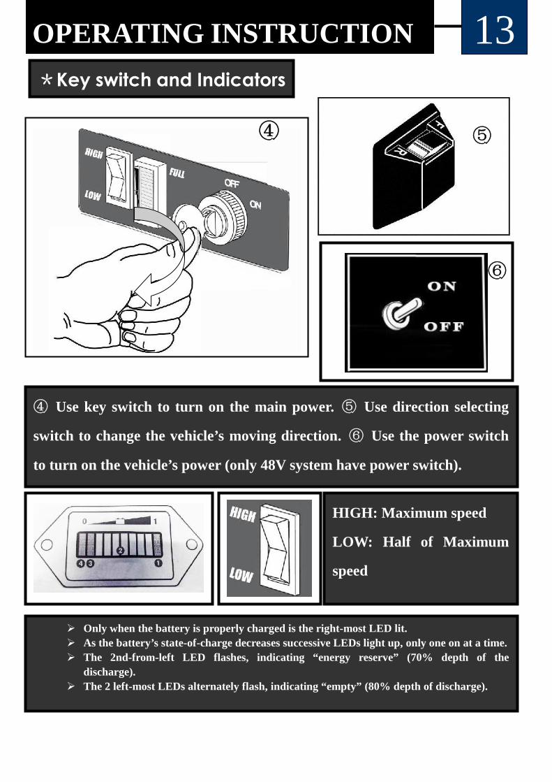
④ Use key switch to turn on the main power. ⑤ Use direction selecting
switch to change the vehicle’s moving direction. ⑥ Use the power switch
to turn on the vehicle’s power (only 48V system have power switch).
*Key switch and Indicators
OPERATING INSTRUCTION 13
Only when the battery is properly charged is the right-most LED lit. As the battery’s state-of-charge decreases successive LEDs light up, only one on at a time. The 2nd-from-left LED flashes, indicating “energy reserve” (70% depth of the
discharge). The 2 left-most LEDs alternately flash, indicating “empty” (80% depth of discharge).
HIGH: Maximum speed
LOW: Half of Maximum
speed
14OPERATING INSTRUCTION
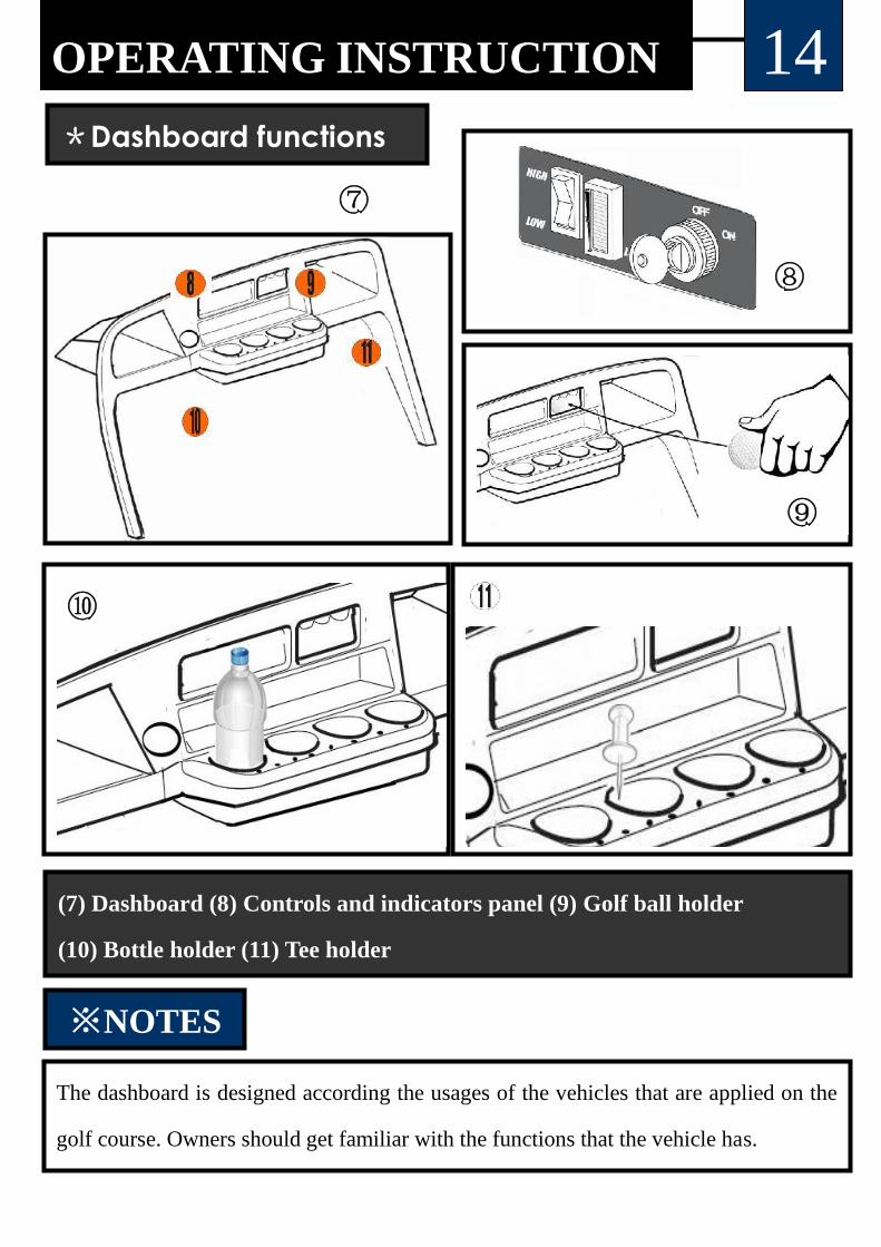
(7) Dashboard (8) Controls and indicators panel (9) Golf ball holder
(10) Bottle holder (11) Tee holder
⑦
⑧
⑨
⑩
※NOTES
The dashboard is designed according the usages of the vehicles that are applied on the
golf course. Owners should get familiar with the functions that the vehicle has.
*Dashboard functions
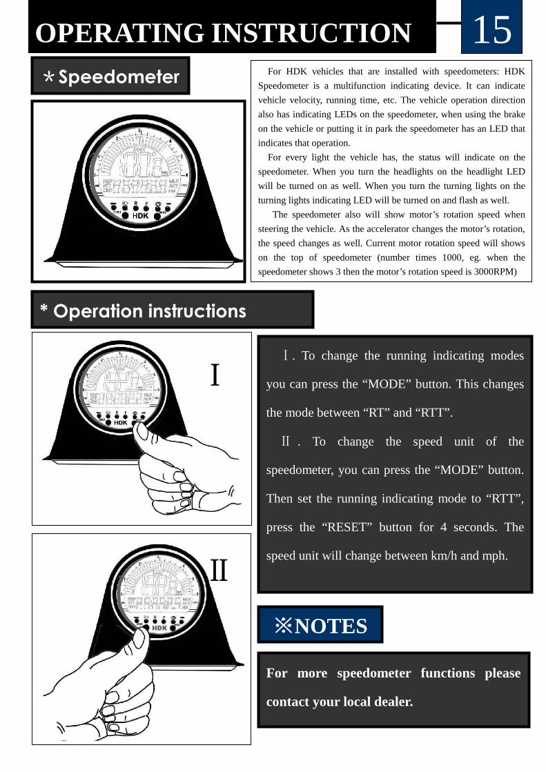
OPERATING INSTRUCTION 15*Speedometer For HDK vehicles that are installed with speedometers: HDK
Speedometer is a multifunction indicating device. It can indicate
vehicle velocity, running time, etc. The vehicle operation direction
also has indicating LEDs on the speedometer, when using the brake
on the vehicle or putting it in park the speedometer has an LED that
indicates that operation.
For every light the vehicle has, the status will indicate on the
speedometer. When you turn the headlights on the headlight LED
will be turned on as well. When you turn the turning lights on the
turning lights indicating LED will be turned on and flash as well.
The speedometer also will show motor’s rotation speed when
steering the vehicle. As the accelerator changes the motor’s rotation,
the speed changes as well. Current motor rotation speed will shows
on the top of speedometer (number times 1000, eg. when the
speedometer shows 3 then the motor’s rotation speed is 3000RPM)
Ⅰ. To change the running indicating modes
you can press the “MODE” button. This changes
the mode between “RT” and “RTT”.
Ⅱ . To change the speed unit of the
speedometer, you can press the “MODE” button.
Then set the running indicating mode to “RTT”,
press the “RESET” button for 4 seconds. The
speed unit will change between km/h and mph.
Ⅰ
*
Ⅱ
* Operation instructions
※NOTES
For more speedometer functions please
contact your local dealer.

16OPERATING INSTRUCTION*Lights and Horn control
Ⅰ. Turn on the right turning lights Ⅱ. Turn on the left turning lights
Ⅲ. Horn button Ⅳ. Turn on the headlights
Ⅰ
Ⅱ
Ⅲ Ⅳ
Switch assembly
Grand information of operation
Always use the vehicle in a responsible manner and maintain the vehicle in safeoperating condition.Always read and observe all warnings and operation instruction labels affixed to thevehicle.Always follow all safety rules established in the area where the vehicle is beingoperated.Always reduce speed to compensate for poor terrain or conditions.Always apply service brake to control speed on steep grades.Always maintain adequate distance between vehicles.Always reduce speed in wet areas.Always use extreme caution when approaching sharp or blind turns.Always use extreme caution when driving over loose terrain.Always use extreme caution in areas where pedestrians are present.
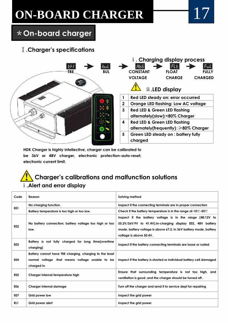
1 Red LED steady on: error occurred2 Orange LED flashing: Low AC voltage3 Red LED & Green LED flashing
alternately(slow):<80% Charger4 Red LED & Green LED flashing
alternately(frequently):≥80% Charger5 Green LED steady on : battery fully
charged
Code Reason Solving method
E01No charging function. Inspect if the connecting terminals are in proper connection
Battery temperature is too high or too low. Check if the battery temperature is in the range of-10℃-50℃
E02No battery connection; battery voltage too high or too
low.
Inspect if the battery voltage is in the range (48:12V to
55.2V/36V:9V to 41.4V).In-charging display E02, 48V battery
mode, battery voltage is above 67.2; In 36V battery mode, battery
voltage is above 50.4V.
E03Battery is not fully charged for long time(overtime
charging)Inspect if the battery connecting terminals are loose or rusted
E04
Battery cannot have TRE charging, charging to the least
normal voltage .that means voltage unable to be
charged in.
Inspect if the battery is shorted or individual battery cell damaged
E05 Charger internal temperature highEnsure that surrounding temperature is not too high, and
ventilation is good ,and the charger should be turned off .
E06 Charger internal damage Turn off the charger and send it to service dept for repairing
E07 Grid power low Inspect the grid power
RL1 Grid power alert Inspect the grid power
ⅰ.Charging display process
TRE BUL CONSTANTVOLTAGE
FLOATCHARGE
FULLYCHARGED
Ⅰ.Charger’s specifications
ⅱ.LED display
ⅰ.Alert and error displayCharger’s calibrations and malfunction solutions
HDK Charger is highly intellective, charger can be calibrated tobe 36V or 48V charger, electronic protection-auto-reset,electronic current limit.
ON-BOARD CHARGER 17*On-board charger

18ON-BOARD CHARGER*On-board chargerⅱ. Charger’s calibration
BEFORE CHARGING, HDK ONBOARD CHARGER HAS TO BE STRICTLYCALIBRATED TO CORRECT CODEWHICH IS DESIGNED FOR SPECIFICBATTERY
48V 36V BATTERY 48V 36V BATTERY
b01 b51 Trojan flooded b15 b65 Trojan T875
b02 b52 Trojan T105 flooded b16 b66 Us 2000 flooded
b03 b53 Discover 80-150AH AGM b17 b67 US2200 flooded
b04 b54 Discover AGM b18 b68 Us 250hc flooded
b05 b55 US battery flooded b19 b69 6TB-170AGM
b06 b56 Trojan 30XHS b20 b70 Generic 140-200Ah AGM
b08 b58 Trojan J305 b21 b71 Generic 200-250 Ah AGM
b09 b59 Generic 200-255 Ah flooded b22 b72 Generic 250-335 Ah AGM
b11 b61 Trojan 1275 b26 b76 Generic 140-200Ah flooded
b13 b63 Trojan T605 b27 b77 Generic 250-335Ah flooded
b14 b64 12TB-115AGM b28 b78 Generic 400Ah flooded
PROGRAM CODE CONTRAST TABLE
Operation illustration
Ⅰ. Inspection of the charger acquiescent charging category
Entering display charge category mode:
ⅰ. Disconnect AC input wires.
ⅱ. Disconnect between the charger output and battery.
ⅲ. A. When AC input is connected the display will show the program revision. After around 5 seconds later, it will show the
charger output voltage and complete the self-inspection process.
B. Display continues to show b01 10 seconds, exit the acquiescent charging mode, display shows E02.ⅳ. Disconnect AC in put wires. If there is need to change the charging category setting, the positive (Red)/negative (Black)
terminals of the output wires should be connected to the battery positive (Red)/negative (Black) terminals. After connecting
the grid power, the charger can start charging the battery code.
ⅴ. Turn on the power of the calibration box ,press button “+ “to increase code number , press “-“ to decrease the code
number ;until to the right code of the battery .
Press “SAVE” button to save the setting, the code display will flash after save the setting.
①
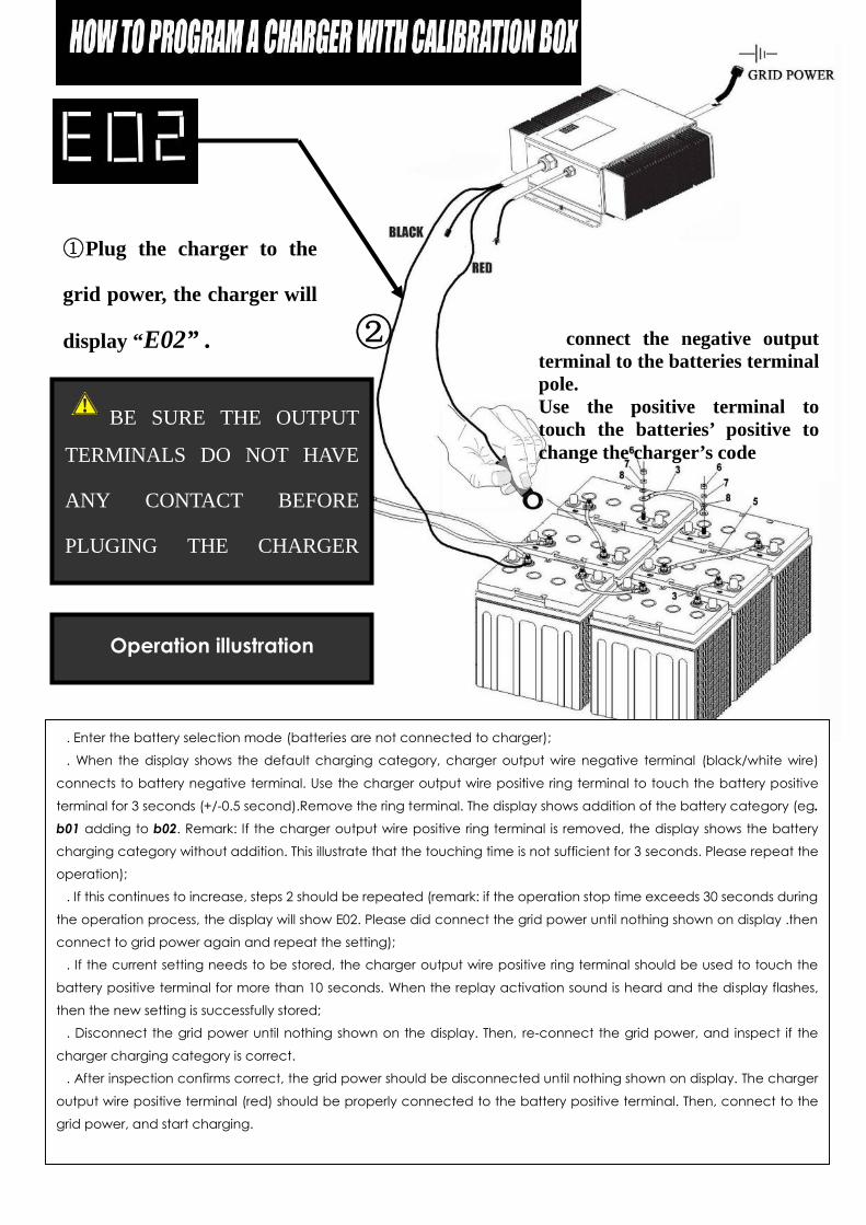
Ⅰ. Enter the battery selection mode (batteries are not connected to charger);
Ⅱ. When the display shows the default charging category, charger output wire negative terminal (black/white wire)
connects to battery negative terminal. Use the charger output wire positive ring terminal to touch the battery positive
terminal for 3 seconds (+/-0.5 second).Remove the ring terminal. The display shows addition of the battery category (eg.b01 adding to b02. Remark: If the charger output wire positive ring terminal is removed, the display shows the battery
charging category without addition. This illustrate that the touching time is not sufficient for 3 seconds. Please repeat the
operation);
Ⅲ. If this continues to increase, steps 2 should be repeated (remark: if the operation stop time exceeds 30 seconds during
the operation process, the display will show E02. Please did connect the grid power until nothing shown on display .then
connect to grid power again and repeat the setting);
Ⅳ. If the current setting needs to be stored, the charger output wire positive ring terminal should be used to touch the
battery positive terminal for more than 10 seconds. When the replay activation sound is heard and the display flashes,
then the new setting is successfully stored;
Ⅴ. Disconnect the grid power until nothing shown on the display. Then, re-connect the grid power, and inspect if the
charger charging category is correct.
Ⅵ. After inspection confirms correct, the grid power should be disconnected until nothing shown on display. The charger
output wire positive terminal (red) should be properly connected to the battery positive terminal. Then, connect to the
grid power, and start charging.
①②
Operation illustration
①Plug the charger to the
grid power, the charger will
display “E02” . ② connect the negative outputterminal to the batteries terminalpole.Use the positive terminal totouch the batteries’ positive tochange the charger’s code
BE SURE THE OUTPUT
TERMINALS DO NOT HAVE
ANY CONTACT BEFORE
PLUGING THE CHARGER
GRID

20ON-BOARD CHARGER
ONLY PROFESSIONAL PERSONS ARE ALLOWED TO CONDUCT THE ADJUSTING OR REPAIRS ON
CHARGER. ANYONE WHO HAS NO EXPERIENCE ON ELECTRONIC COMPONENTS MAINTENANCE IS NOT
ALLOWED TO OPERATE ON THE CHARGER. UNREQUIED OPERATIONS ON THE CHARGER MAY CAUSE
ELECTRIC SHOCK, AND MAY LEAD TO DEATH
USE THE CHARGER ONLY WITH AN ALGORITHM SELECTED THAT IS APPROPRIATE TO THE SPECIFIC
BATTERY TYPE. OTHER USAGE MAY CAUSE PERSONAL INJURY AND DAMAGE. LEAD ACID BATTERIES
MAY GENERATE EXPLOSIVE HYDROGEN GAS DURING NORMAL OPERATION. KEEP SPARKS, FLAMES,
AND SMOKING MATERIALS AWAY FROM BATTERIES.
PROVIDE ADEQUATE VENTLIATION DURING CHARGING. NEVER CHARGE A FROZEN BATTERY.
BATTERIES’ CAPS SHOULD BE REMOVED WHILE CHARGING.
RISK OF THE ELECTRIC SHOCK: CONNECT CHARGER POWER CORD TO AN OUTLET THAT HAS
BEEN PROPERLY ISTALLED AND GROUNDED IN ACCORDANCE WITH ALL LOCAL CODES AND
ORDINANCES. A GROUND OUTLET IS REQUIRED TO REDUCE RISKOF THE ELECTRIC SHOCK. DO NOT
USE GROUND ADAPTERS OR MODIFY PLUG.. DO NOT TOUCH UNINSULATED PORTION OF THE OUTPUT
CONNECTOR OR UNINSULATED BATTERY TERIMALS.
CHILDREN SHOULD BE SUPERVISED TO ENSURE THAT THEY DO NOT PLAY WITH THE APPLIANCE
DO NOT OPEN UP THE CHARGER. ANY ATTEMPTIONS TO TRY TO REPAIR THE DEFECT CHARGER
SHOULD UNDER THE GUIDANCE OF DEALER OR MANUFACTURER’S TECHNICIAN.
※NOTES
HDK on-board charger is specially designed for HDK vehicles. The charger’s workingvoltage range from 85V~265V, working frequency range from 45HZ ~65HZ. Customersfrom all over the world can use HDK on-board without any changes.HDK on-board charger can be operated in the temperature -30℃~+50℃(-22℉~122℉), whichallows HDK on-board charger to be used in most circumstances.

Trojan flooded Trojan T875
Trojan T105 flooded Us 2000 flooded
Discover 80-150AH
AGM
US2200 flooded
Discover AGM Us 250hc flooded
US battery flooded 6TB-170AGM
Trojan 30XHS Generic 140-200Ah
AGM
Trojan J305 Generic 200-250 Ah
AGM
Generic 200-255 Ah
flooded
Generic 250-335 Ah
AGM
Trojan 1275 Generic 140-200Ah
flooded
Trojan T605 Generic 250-335Ah
flooded
12TB-115AGM Generic 400Ah
flooded
21BATTERIES
*HDK vehicle batteries connection
Batteries loaded on HDK vehicles, according to differentconfigurations, customers who purchase HDK vehicles canchoose different batteries (figure② are the batteriesavailable).The batteries are connected in series circuitpattern:System Battery QTY(PCS) Single battery voltage(V)
36V 6 648V 6 848V 8 6
Batteries HDK vehicles can apply
①
②
ⅰ. The exterior of the battery, the connection wires and bolts should be kept clean and dry. If there is electrolyte outside the battery, please clean with
dry cotton cloth first, then wash with water and finally wipe up. (While cleaning, do not allow any cleaning solution, or water to get inside the battery,
to avoid leakage and increasing self-discharge, always use baking soda and water only to clean batteries)
ⅱ. The connection of the battery should always be kept in good condition. please check if any battery cable terminal or nut has become loose
periodically in order to prevent any sparkle or damage to terminals.
ⅲ. Do not place any object on the battery and do not connect the positive pole to the negative pole .this may cause a short circuit, damage to the
battery or injury to your body.
ⅳ. The battery should be recharged fully when not in use. Any delay on the re-charging will cause negative effect on the battery.
ⅴ. The evaporation and electrolyzing of the water will cause the density of electrolyte of the battery increased and the liquid surface decrease,
especially in hot weather. Therefore, check the distilled water or the attenuated sulfuric acid for lead-acid battery with density of 1.40 to adjust the
electrolyte to meet the density of the 1.28, the surface should be flat with highest level then continue to charge 0.5-1 hour in order to make the internal
uniform .
ⅵ. Any impurities are not allowed to enter the battery. Keep the apparatus clean for adding water to avoid the impurities to be fallen into the battery.
ⅶ. When driving, the driver shall be always be aware of the drop level the battery power from the batteries’ capacity indicator. the driver shall
estimate the distance needed to be taken, and recharge the battery at a proper time in case that the car cannot get back to the recharging station in
time for recharging . ⅷ. If the golf car is going to be kept unused for a period of time, the battery shall be fully charged before put away. After that,
the battery fully recharged every month, until the charger turn off automatically
ⅸ. During charging, the car shall be parked in a well-ventilated area with the fill caps open. Keep car far away from any frame and sparks and avoid
any explosion or fire that could cause physical injury or damage to the property.
ⅹ. Once charged the cap should be kept tightly covered.

①
②
③
①
②
③
④While fastening the wheel nuts, one should always
keep itin a cross-sequence. To attach the perfect tightsituation.
Front hub brake drum Dust cover Dust cover seal Tire wheel fasten nut
For different circumstances the vehicle being used, different tire treads are
optional, the standard tires HDK vehicles have are turf tires.
FIGURE ① STANDARD TREADFIGURE ② PREMIUM TREADFIGURE ③ EXTRA TRACTION
CROSS-SEQUENCE
1. Clean both tire beads to remove dirt or other object.
2. Where the tire beads seat, clean the wheel rim with a wire brush.
3. Apply plenty of tire mounting lubricant (soap and solution) to both
beads and rim flanges.
4. Install the tire on the rim from the valve stem side. If there is no tire
machine available, use a rubber mallet and tire iron.
5. Remove the valve core and position tire so that both beads are on
the rim flange narrow bead seats.
6. Quickly remove the air nozzle and install the valve core.
7. Adjust the tire, keep the air pressure between 3.5-4.0MP, immerse
the tire into water to make sure there are no leaks.
Tubeless tire cautions
FOR ATTACHING THE MAXIUM PEFORMANCE THE TIRES
SHOULD ALWAYS BE CHOOSEN ACCORDING TO THE CIRCUSTANCES
THE VEHICLE MOSTLY BEEN USED.
TIRES 22*Vehicle Tires’ tread
1.
23VEHICLE MODIFICATIONS
*VEHICLE PREFORMANCE REMODIFICATION
Ⅰ. Controller adjustment
For attaching different speed performance or regenerative brake effect; The ramp climbing abilityor low speed cruising pattern performance re-modification all can be done by changing thecontroller’s parameter setting.
Ask dealer or manufacturer for specific information about remodify the controller parameters.
The motor and rear axle’s performance are fixed when the customer buys it from dealer. The ratedpower and torque capability are limited due to the vehicle’s configuration.
For attaching different torque and power performances, customers can choose different motors orrear axles as options to remodify the vehicle configurations.MOTOR OPTIONS; 3kw/4kw/5kwREAR AXLE OPTIONS (SORTED BY RATIOS) : 10.25:1 / 12.49:1REAR AXLE OPTIONS (SORTED BY RATIOS ) : 10.25:1 / 12.49:1
Ⅱ. Motor and rear axle
ONLY TRAINED PERSONS ARE ALLOWED TO REMODIFY CONTROLLER PARAMETERS SETTINGS. ANY
INPROPER SETTING CHANGES MAY CAUSE SEVERE DAMAGES TO THE VEHICLE OR JEOPARDISE
PASSENGERS SAFTY.
ONLY PERSONS WHO HAVE EXPERIENCE WITH REAR AXLE AND MOTOR MAINTENANCES ARE
ALLOWED TO CONDUCT MODIFICATIONS.
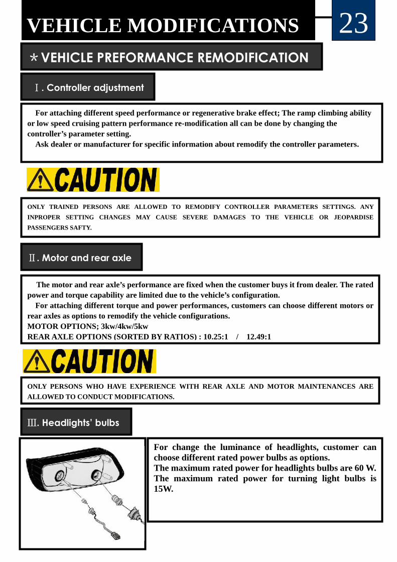
Ⅲ. Headlights’ bulbs
For change the luminance of headlights, customer canchoose different rated power bulbs as options.The maximum rated power for headlights bulbs are 60 W.The maximum rated power for turning light bulbs is15W.
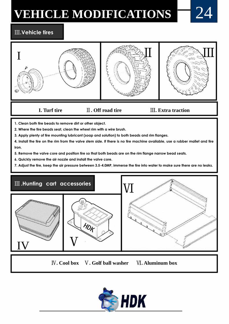
24Ⅲ.Vehicle tires
1. Clean both tire beads to remove dirt or other object.2. Where the tire beads seat, clean the wheel rim with a wire brush.3. Apply plenty of tire mounting lubricant (soap and solution) to both beads and rim flanges.4. Install the tire on the rim from the valve stem side. If there is no tire machine available, use a rubber mallet and tireiron.5. Remove the valve core and position tire so that both beads are on the rim flange narrow bead seats.6. Quickly remove the air nozzle and install the valve core.7. Adjust the tire, keep the air pressure between 3.5-4.0MP, immerse the tire into water to make sure there are no leaks.
Ⅰ Ⅱ Ⅲ
I. Turf tire Ⅱ. Off road tire Ⅲ. Extra traction
Ⅲ .Hunting cart accessories
option
Ⅳ
Ⅴ
Ⅵ
Ⅳ. Cool box Ⅴ. Golf ball washer Ⅵ. Aluminum box
VEHICLE MODIFICATIONS
I
IV

25VEHICLE MAINTENANCE
①
⑤
① Wrenches ② Retaining ring pliers ③ Battery fluid injection tool faucet
④ Tire air inflating tool ⑤ Hydrometer ⑥ Lubricant can
⑦ Charger’s calibration box ⑧ Multimeter ⑨ Tape measure ⑩ Jack
Ⅰ.Tools
①
② ③
④
⑤
⑥ ⑦
⑩
⑧ ⑨
※NOTES
All the maintenance tools are available from hardware stores.
.
VEHICLE MAINTENANCE 26Ⅱ.Vehicle maintenance
Always:• Maintain the vehicle in accordance with the manufacturer’s periodic service schedule.• Ensure that repairs are performed by those that are trained and qualified to do so.• Follow the manufacturer’s maintenance procedures for the vehicle. Be sure to disablethe vehicle before performing any maintenance. Disabling includes removing the keyfrom the key switch and removal of a battery wire.• Insulate any tools used within the battery area in order to prevent sparks or batteryexplosion caused by shorting the battery terminals or associated wiring. Remove thebatteries or cover exposed terminals with an insulating material.• Check the polarity of each battery terminal and be sure to rewire the batteries correctly.• Use specified replacement parts. Never use replacement parts of lesser quality.• Use recommended tools.• Determine that tools and procedures not specifically recommended by the manufacturerwill not compromise the safety of personnel nor jeopardize the safe operation of thevehicle.• Support the vehicle using wheel chocks and jack stands. Never get under a vehicle thatis supported by a jack. Lift the vehicle in accordance with the manufacturer’sinstructions.• Maintain the vehicle in an area away from exposed flame or persons who are smoking.• Be aware that a vehicle that is not performing as designed is a potential hazard andmust not be operated.• Test drive the vehicle after any repairs or maintenance. All tests must be conducted in asafe area that is free of both vehicular and pedestrian traffic.• Replace damaged or missing warning, caution or information labels.• Keep complete records of the maintenance history of the vehicle.The manufacturer cannot anticipate all situations, therefore people attempting tomaintain or repair the vehicle must have the skill and experience to recognize and protectthemselves from potential situations that could result in severe personal injury or deathand damage to the vehicle. Use extreme caution and, if unsure as to the potential forinjury, refer the repair or maintenance to a qualified mechanic.
27ⅰ. Chassis maintenance
VEHICLE MAINTENANCE
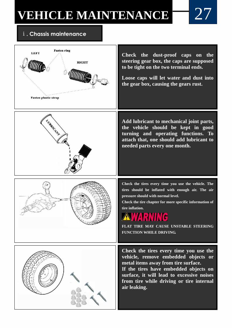
Check the dust-proof caps on thesteering gear box, the caps are supposedto be tight on the two terminal ends.
Loose caps will let water and dust intothe gear box, causing the gears rust.
Add lubricant to mechanical joint parts,the vehicle should be kept in goodturning and operating functions. Toattach that, one should add lubricant toneeded parts every one month.
Check the tires every time you use the vehicle. The
tires should be inflated with enough air. The air
pressure should with normal level.
Check the tire chapter for more specific information of
tire inflation.
FLAT TIRE MAY CAUSE UNSTABLE STEERING
FUNCTION WHILE DRIVING.
Check the tires every time you use thevehicle, remove embedded objects ormetal items away from tire surface.If the tires have embedded objects onsurface, it will lead to excessive noisesfrom tire while driving or tire internalair leaking.

28VEHICLE MAINTENANCECheck the lubricant capacity of rear axle.Low lubricant capacity may cause damagesto the rear axle cams or cause excessivenoises.
Maintenance period: change the lubricantof rear axle every 6 months.
Clear the brake shoes surface, all the brakeshoes shed dust and should be cleaned outin periodic time. Shed dust may causemechanical malfunctions of brake.Use a compressed air to blow the dust out.
Maintenance period: one time per month.
Check the brake shoes worn out conditions,if it is extremely worn out (1/3 left), thenthe brake shoes need to be replaced with anew one.
DO NOT DRIVE THE VEHICLE WITHPOOR BRAKE.
Check the bearings inside of front hub, thehubs should have enough lubricated grease.
Maintenance period: one per 6 month.
29ⅱ.Electric components maintenance
VEHICLE MAINTENANCE
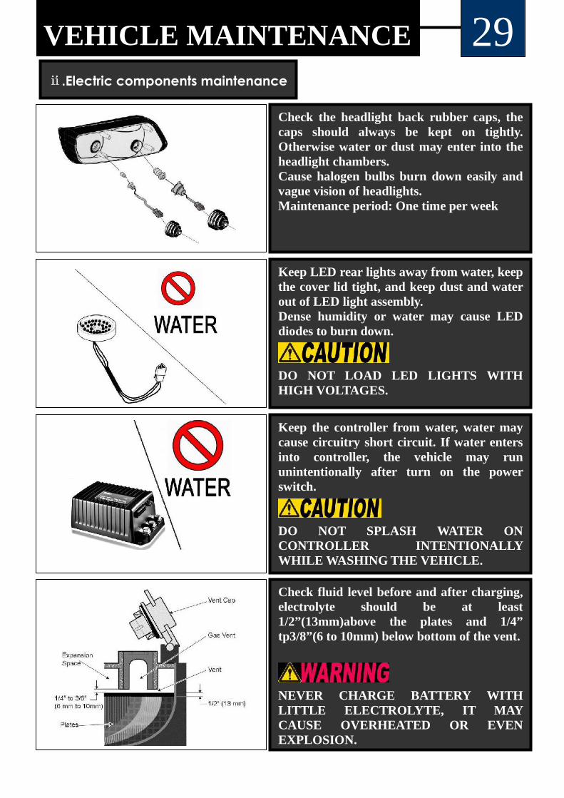
Check the headlight back rubber caps, thecaps should always be kept on tightly.Otherwise water or dust may enter into theheadlight chambers.Cause halogen bulbs burn down easily andvague vision of headlights.Maintenance period: One time per week
Keep the controller from water, water maycause circuitry short circuit. If water entersinto controller, the vehicle may rununintentionally after turn on the powerswitch.
DO NOT SPLASH WATER ONCONTROLLER INTENTIONALLYWHILE WASHING THE VEHICLE.
Keep LED rear lights away from water, keepthe cover lid tight, and keep dust and waterout of LED light assembly.Dense humidity or water may cause LEDdiodes to burn down.
DO NOT LOAD LED LIGHTS WITHHIGH VOLTAGES.
Check fluid level before and after charging,electrolyte should be at least1/2”(13mm)above the plates and 1/4”tp3/8”(6 to 10mm) below bottom of the vent.
NEVER CHARGE BATTERY WITHLITTLE ELECTROLYTE, IT MAYCAUSE OVERHEATED OR EVENEXPLOSION.

30VEHICLE MAINTENANCE
Use a hydrometer to check the specific gravity of the
battery fluid in each cell.
Fluid density ranges from different values in different
period of battery using
Maintenance period: One time per month.
Never use an injection faucet to inject distilledwater into the battery when the batterydoesn’t have enough capacity of battery fluid.
Maintenance period: One time per month
Always remember to takeprecautions while conductingany operations on batteries orhandling batteries.
Wear gloves to protect personfrom acid corrosion.
Wear glass to protect personfrom acid splash.
Always remember to washhands after handling batteryor touch battery’s cap andbattery terminals

31VEHICLE STORAGE
If the vehicle is put away for storage for long time, certain things need to be
done to prevent vehicle from malfunctions or other loss.
Please always follow the methods shown below.
Ⅰ. Keep vehicle in dry and ventilated place, keep it from rain.
Ⅱ.Remember to charge the batteries fully before put away vehicle.
Ⅲ.Disassemble the connection cables between batteries and controller.
Ⅰ
Ⅱ
Ⅲ
I

Parameters and specs are approximate only and may vary
Parameter
Type
DEL 2022D Series Electric Hunting Cart
DEL 2022D DEL 2022D2Z DEL2042D DEL 2042D2Z
Passenger capacities 2 4 4 6
Dimension (mm) (L×W×H)2350×1260×
1830
2610×1260×
1830
3100×1260×
1830
3360×1260×
1830
Range (based on flat road ata speed of 20 km/h) (km/h)
80 75 65 60
Maximum speed (gear ratioof 12.49:1)km/h
40 38 35 35
Maximum grade ability 30% 28% 25% 22%
Minimum turning diameter(m)
3.1 3.1 4.3 4.3
Brake distance (V=20km/h) ≤3.5m ≤3.8m ≤4.0m ≤4.0
Minimum distance fromfloor(mm)
150 150 150 150
Noise (db)63 63 63 63
32SPECIFICATION

33SPECIFICATION
Approximate only and may vary
Max slope accessing angle Max ramp angle

NOTE

NOTE

NOTE

NOTE

HDK Vehicles USA, LLC.
2112 First Street
Rosenberg TEXAS 77471
Tel: 281-342-1040 Fax: 281-342-6432
Email:
Website: www.hdkusa.com