owner s manual - klima-vertrieb · a few words about your new air conditioning unit electrical data...
TRANSCRIPT

Recreational Vehicle Air Conditioner
OWNER’S MANUAL
Model: GRH085DA-K3NA1A
Thank you for choosing our product.
If you have lost the Owner’s Manual, please contact the local agent or visit www.gree.com or sent email to [email protected] for electronic version.
For proper operation, please read and keep this manual carefully.

CONTENTS
A FEW WORDS ABOUT YOUR NEW AIR CONDITIONING UNIT .......................................1
ELECTRICAL DATA ..............................................................................................................1
OPERATION OF WIRELESS REMOTE CONTROLLER ......................................................7
CONTROL PANEL ..............................................................................................................14
CONTROL PANEL(WIFI).....................................................................................................15
NORMAL MAINTENANCE PROCEDURES .......................................................................23
ELECTRIC DIAGRAM ...........................................................................................................2
ELECTRIC DIAGRAM(WIFI) .................................................................................................3
INSTALLATION INSTRUCTION..........................................................................................16
STEP 3-ELECTRICAL WIRING ..................................................................................................20
STEP 4-COMPLETING THE INSTALLATION .................................................................................21
STEP 2-INSTALLING THE CEILING ASSEMBLY .............................................................................19
STEP 1-SELECTING AN INSTALLATION LOCATION & INSTALLING THE ROOF TOP AIR CONDITIONER ......16
TROUBLESHOOTING GUIDE ............................................................................................22
PACKING LIST ......................................................................................................................4
SPECIFICATIONS .................................................................................................................5
PARTS NAME........................................................................................................................6
●
●
●●
This appliance is not intended for use by persons (including children) with reduced physical, sensory or mental capabilities, or lack of experience and knowledge,unless they have been given supervision or instruction concerning use of theappliance by a person responsible for their safety. Children should be supervisedto ensure that they do not play with the appliance.This appliance can be used by children aged from 8 years and above and persons
Children shall not play with the appliance.Cleaning and user maintenance shall not be made by children without supervision.
with reduced physical, sensory or mental capabilities or lack of experience and knowledge if they have been given supervision or instruction concerning use of the appliance in a safe way and understand the hazards involved.

INSTALLATION PRECAUTIONWARNING:
● Observe all governing codes and ordinances.● Do not use damaged or non-standard power cord.● Be caution during installation and maintenance. Prohibit inco
Suggested working temperature range: +4 ~ 46℃. Outdoor unit may stop operation
rrect operation to prevent electric shock, casualty and other accidents.
due to various kinds of protection within working temperature range.
Selection of Installation Location
Working temperature range
Basic requirementInstalling the unit in the following places may cause malfunction. If it is unavoidable, please consult the local dealer:
volatile objects spread in the air.2. The place with high-frequency devices (such as welding machine, medical equipment).3. The place near coast area.4. The place with oil or fumes in the air.5. The place with sulfureted gas.6. Other places with special circumstances.Requirement of air conditioner1. Air inlet should be far away from obstacles and do not put any objects near air outlet. Otherwise, it will affect the radiation of heat-removal pipe.
not affect neighborood.
4.The appliance shall not be installed in the laundry.
Requirements Forelectric ConnectionSafety precaution1. Must follow the electric safety regulations when installing the unit.
3. For appliances with type Y attachment,the instructions shall contain the substance of the following.If the supply cord is damaged,it must be replaced by
4. Properly connect the live wire, neutral wire and grounding wire of power socket.. Be sure to cut off the power supply before proceeding any work related to electricity and safety.5
with specialized grounding device by a professional. Please make sure it is always grounded effectively, otherwise it may cause electric shock.8. The yellow-green wire or green wire in air conditioner is grounding wire, which can't be used for other purposes.9. The grounding resistance should comply with national electric safety regulations.10. The appliance shall be installed in accordance with national wiring regulations
avoid a hazard.
A FEW WORDS ABOUT YOUR NEWAIR CONDITIONING UNIT
ELECTRICAL DATA
1. All wiring must be complied with local and national electrical codes. All wiring must be installed by qualified electricians. If you have any questions about the following instructions, contact a qualified electrician.
2. Check the available power supply and resolve any wiring problems BEFORE installingand operating this unit.
3. This air conditioner is designed to operate from a 220-240V AC, 50Hz, 1 Phase power supply.
4. The wiring diagrams are located on the cover of the control box. The assembly unit wire diagrams are located on the ceiling panel.
- 1 -
Thank you for choosing the Recreational Vehicle Air Conditioner. This manual will supply you with all the information for installation, operation and maintenance.Take a few minutes to discover how to get the most in cooling comfort and economic operationfrom your new air conditioner.
Please keep this manual well for future reference.

Ceiling Assembly
ELECTRIC DIAGRAM
Roof Top Air Conditioner
- 2 -
Notice: Use Copper Conductors Only.
M1
STEPPINGMOTOR
M2
STEPPINGMOTOR
AP2
LEDBOARD
OUTD
OOR
UNIT
RT1ROOMSENSORAP1
DISPLAY
DISP1
SW1 SW2 CN1
DISP2
DISP3
BOARD
YEGN(GN)
BU(WH)
BN
L
N
POWERPE
L
N
BU
YEGN
BN(BK)
TERMINALBLOCK
CAP. YE
BU
BU
R
S
INDOOR UNIT
OUTROOMSENSOR
YAW4 N
VALVE4-WAY
4YV
MOTOR
DISP1
N1 COMP
PE
OUT_FAN
AC-L1
PE
BUBN
YEGN
DISP2 AP1
YEGNPE
ELECTRIC BOX
PE
YEGN
M3
PEYEGN
OUT_FAN1
MOTORIN_FAN
PEYEGN
IN_FAN
M1
OUTTUBE SENSOR
CN5
RT1
TUBESENSOR
RT2
CN4
OUT_FAN
MAIN BOARD
RT3
M2
(20K) (15K)(20K)(WH) (BK)
VT VT
K1
MOTOROUT_FAN
C
RD
COMP
YEGN
PECOMP.
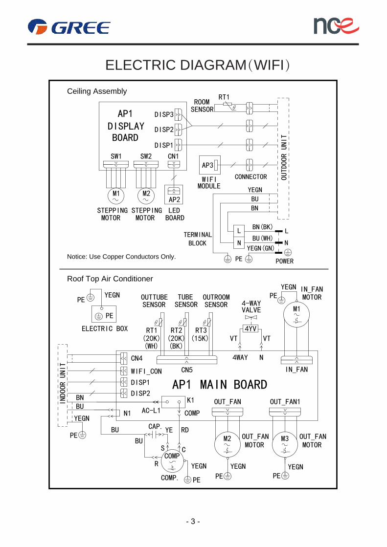
ELECTRIC DIAGRAM(WIFI)
Roof Top Air Conditioner
- 3 -
Notice: Use Copper Conductors Only.
Ceiling Assembly
M1
STEPPINGMOTOR
M2
STEPPINGMOTOR
AP2
LEDBOARD
OUTD
OOR
UNIT
RT1ROOMSENSORAP1
DISPLAY
DISP1
SW1 SW2 CN1
DISP2
DISP3
BOARD
YEGN(GN)
BU(WH)
BN
L
N
POWERPE
L
N
BU
YEGN
BN(BK)TERMINALBLOCK
CONNECTOR
AP3
WIFI MODULE
CAP. YE
BU
BU
R
S
INDOOR U
NIT
OUTROOMSENSOR
YAW4 N
VALVE4-WAY
4YV
MOTOR
DISP1
N1 COMP
PE
OUT_FAN
AC-L1
PE
BUBN
YEGN
DISP2AP1
YEGNPE
ELECTRIC BOX
PE
YEGN
M3
PEYEGN
OUT_FAN1
MOTORIN_FAN
PEYEGN
IN_FAN
M1
OUTTUBE SENSOR
CN5
RT1
TUBESENSOR
RT2
CN4
OUT_FAN
MAIN BOARD
RT3
M2
(20K) (15K)(20K)(WH) (BK)
VT VT
K1
MOTOROUT_FAN
WIFI_CON
C
RD
COMP
YEGN
PECOMP.
- 4 -
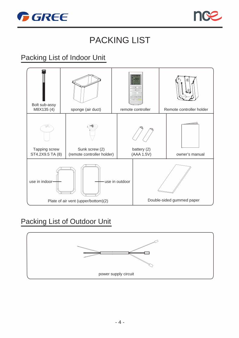
PACKING LIST
Packing List of Outdoor Unit
Packing List of Indoor Unit
Bolt sub-assysponge (air duct) Remote controller holder
Plate of air vent (upper/bottom)(2) Double-sided gummed paper
M8X135 (4)
Tapping screwST4.2X9.5 TA (8)
Sunk screw (2)(remote controller holder)
battery (2)
use in indoor use in outdoor
(AAA 1.5V)
remote controller
LED
TIMER ON
LIGHT
owner’s manual
power supply circuit
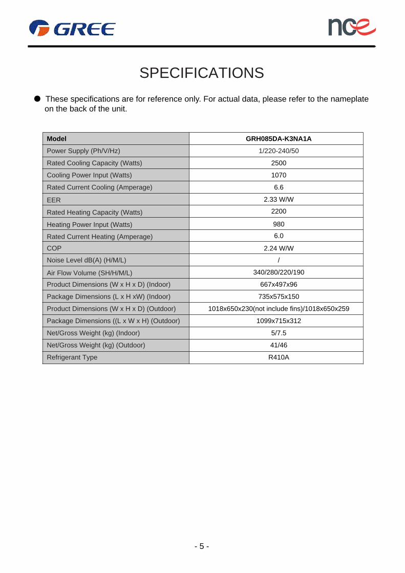
SPECIFICATIONS
- 5 -
● These specifications are for reference only. For actual data, please refer to the nameplate on the back of the unit.
Power Supply (Ph/V/Hz)
Rated Cooling Capacity (Watts)
Cooling Power Input (Watts)
Rated Current Cooling (Amperage)
EER
COP
Rated Current Heating (Amperage)
Heating Power Input (Watts)
Rated Heating Capacity (Watts)
Model GRH085DA-K3NA1A
1/220-240/50
2500
1070
2200
980
6.0
2.24 W/W
6.6
2.33 W/W
Noise Level dB(A) (H/M/L)
Air Flow Volume (SH/H/M/L)
Product Dimensions (W x H x D) (Indoor)
Package Dimensions (L x H xW) (Indoor)
Product Dimensions (W x H x D) (Outdoor)
Package Dimensions ((L x W x H) (Outdoor)
Net/Gross Weight (kg) (Indoor)
Net/Gross Weight (kg) (Outdoor)
Refrigerant Type
340/280/220/190
667x497x96
735x575x150
1018x650x230(not include fins)/1018x650x259
1099x715x312
5/7.5
41/46
R410A
/
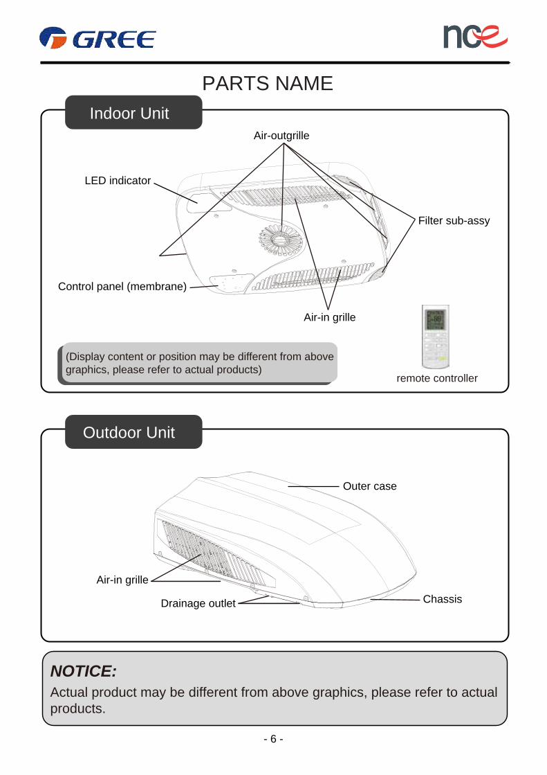
PARTS NAME
LED indicator
Air-in grille
Air-outgrille
Filter sub-assy
Outer case
Chassis
Air-in grille
Drainage outlet
Control panel (membrane)
(Display content or position may be different from above graphics, please refer to actual products)
Indoor Unit
Outdoor Unit
remote controller
Actual product may be different from above graphics, please refer to actual products.
NOTICE:
- 6 -
LED
TIMER ON
LIGHT
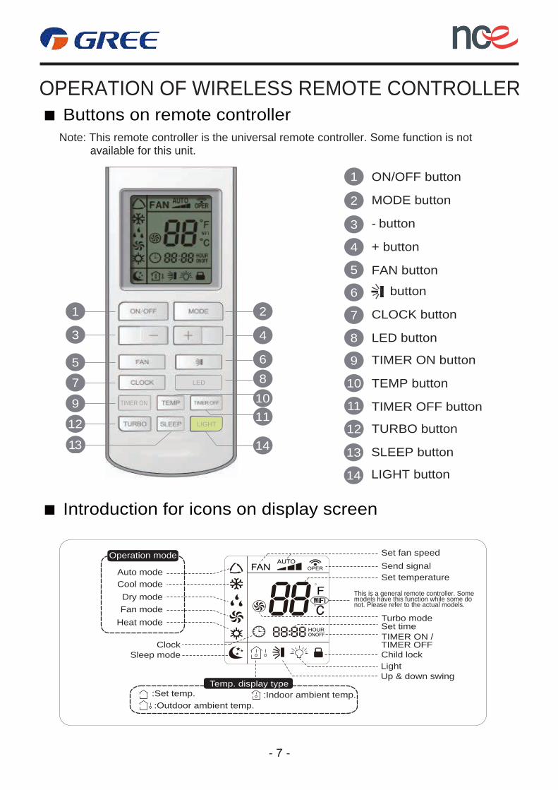
OPERATION OF WIRELESS REMOTE CONTROLLER Buttons on remote controller
Introduction for icons on display screen
- 7 -
Note: This remote controller is the universal remote controller. Some function is not available for this unit.
1
2
3
4
5
6
7
8
9
10
11
12
ON/OFF button
MODE button
- button
+ button
FAN button
LED button
TIMER ON button
TEMP button
TIMER OFF button
TURBO button
13 SLEEP button
14 LIGHT button
CLOCK button
button
1
3
5
7
9
12
2
4
68
1110
1413
Turbo mode
Send signalSet temperature
Set timeTIMER ON /TIMER OFFChild lock
Up & down swing
Set fan speed
Light
Temp. display type:Set temp.:Outdoor ambient temp.
:Indoor ambient temp.
Sleep modeClock
Heat modeFan modeDry mode
Cool modeAuto mode
Operation mode
LED
TIMER ON
LIGHT
This is a general remote controller. Some models have this function while some do not. Please refer to the actual models.
- 8 -
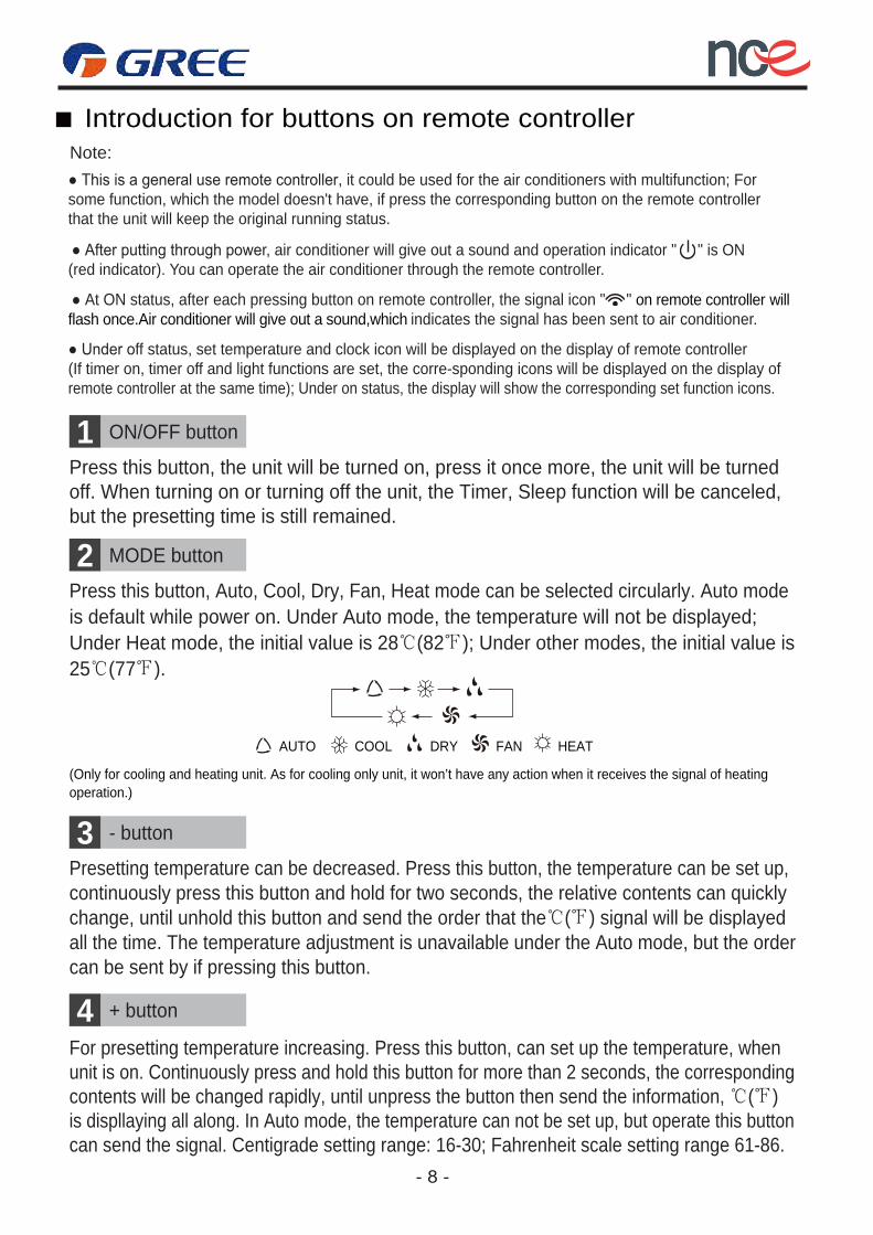
ON/OFF button1Press this button, the unit will be turned on, press it once more, the unit will be turnedoff. When turning on or turning off the unit, the Timer, Sleep function will be canceled,but the presetting time is still remained.
MODE button2Press this button, Auto, Cool, Dry, Fan, Heat mode can be selected circularly. Auto mode
- button3Presetting temperature can be decreased. Press this button, the temperature can be set up,
+ button4For presetting temperature increasing. Press this button, can set up the temperature, whenunit is on. Continuously press and hold this button for more than 2 seconds, the correspondingcontents will be changed rapidly, until unpress the button then send the information, ℃(℉)is displlaying all along. In Auto mode, the temperature can not be set up, but operate this buttoncan send the signal. Centigrade setting range: 16-30; Fahrenheit scale setting range 61-86.
continuously press this button and hold for two seconds, the relative contents can quicklychange, until unhold this button and send the order that the℃(℉) signal will be displayedall the time. The temperature adjustment is unavailable under the Auto mode, but the ordercan be sent by if pressing this button.
is default while power on. Under Auto mode, the temperature will not be displayed;Under Heat mode, the initial value is 28℃(82℉); Under other modes, the initial value is25℃(77℉).
AUTO COOL DRY FAN HEAT
(Only for cooling and heating unit. As for cooling only unit, it won’t have any action when it receives the signal of heating operation.)
● This is a general use remote controller, it could be used for the air conditioners with multifunction; For some function, which the model doesn't have, if press the corresponding button on the remote controller that the unit will keep the original running status.
● After putting through power, air conditioner will give out a sound and operation indicator " " is ON (red indicator). You can operate the air conditioner through the remote controller.
● At ON status, after each pressing button on remote controller, the signal icon " " on remote controller will flash once.Air conditioner will give out a sound,which indicates the signal has been sent to air conditioner.
● Under off status, set temperature and clock icon will be displayed on the display of remote controller (If timer on, timer off and light functions are set, the corre-sponding icons will be displayed on the display of remote controller at the same time); Under on status, the display will show the corresponding set function icons.
Introduction for buttons on remote controllerNote:
- 9 -
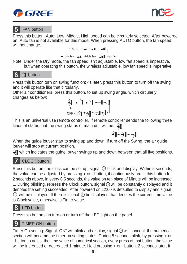
FAN button5Press this button, Auto, Low, Middle, High speed can be circularly selected. After powered
6
Other air conditioners, press this button, to set up swing angle, which circularly
Press this button turn on swing function; 4s later, press this button to turn off the swingand it will operate like that circularly.
changes as below:
This is an universal use remote controller. If remote controller sends the following three kinds of status that the swing status of main unit will be:
When the guide louver start to swing up and down, if turn off the Swing, the air guidelouver will stop at current position.
which indicates the guide louver swings up and down between that all five positions.
on, Auto fan is not available for this mode. When pressing AUTO button, the fan speedwill not change.
Note: Under the Dry mode, the fan speed isn't adjustable, low fan speed is imperative,but when operating this button, the wireless adjustable, low fan speed is imperative.
button
7Press this button, the clock can be set up, signal blink and display. Within 5 seconds,the value can be adjusted by pressing + or - button, if continuously press this button for 2 seconds above, in every 0.5 seconds, the value on ten place of Minute will be increased1. During blinking, repress the Clock button, signal will be constantly displayed and itdenotes the setting succeeded. After powered on,12:00 is defaulted to display and signal
is Clock value, otherwise is Timer value.will be displayed. If there is signal be displayed that denotes the current time value
Middle fanLow fan
AUTO
High fan
OFF
CLOCK button
8Press this button can turn on or turn off the LED light on the panel.
LED button
9Timer On setting: Signal “ON” will blink and display, signal will conceal, the numericalsection will become the timer on setting status. During 5 seconds blink, by pressing + or
will be increased or decreased 1 minute. Hold pressing + or - button, 2 seconds later, it- button to adjust the time value of numerical section, every press of that button, the value
TIMER ON button

- 10 -
TEMP button10Press this button, could select displaying the indoor setting temperature or indoor
TIMER OFF button11Once press this key to enter into TIMER OFF setup, in which case the TIMER OFF
TURBO button12In Cool or Heat mode, press this button can turn on or turn off the Turbo function.
SLEEP button13Press this button, Sleep On and Sleep Off can be selected. After powered on, SleepOff is defaulted. After the unit is turned off, the Sleep function is canceled. After Sleepfunction set up, the signal of Sleep will display.In this mode, the time of timer can beadjusted. Under Fan and Auto modes, this function is not available.
After turned on the Turbo function, its signal will be displayed. When switching themode or changing fan speed, this function will be canceled automatically.
icon will blink. The method of setting is the same as for TIMER ON.
ambient temperature. When the indoor unit firstly power on it will display the settingtemperature, if the temperature's displaying status is changed from other status to
control signal that will return to display the setting temperature. if the users haven'tset up the temperature displaying status, that will display the setting temperature.(This function is applicable to partial of models)After powered on, the setting temperature displaying is defaulted, (according to cust-omers requirements to display, if there is no requirement that will default to display
Press this button, (When displaying ), will display presetting temperature; (whendisplaying ) will display indoor ambient temperature, current displaying statuswill not be changed. If current displays indoor ambient temperature, if received theother remote control signal, it will display presetting temperature, 5s later, will backto display the ambient temperature.(This function is applicable to partial ofmodels)
the presetting temperature and there is no icon displayed on wireless remote control).
" ", displays the ambient temperature, 5s later or within 5s, it receives other remote
button, the timer setting succeeds. The Timer On has been set up, repress the timer On button, the Timer On will be canceled. Before setting the Timer, please adjust the Clock to the current actual time.
in the one place of minute, then the one place is constant, ten numbers change in thetens place of minute at 2.5 seconds speed and carry. During 5s blink, press the Timer
quickly change, the way of change is: During the initial 2.5 seconds, ten numbers change
- 11 -
Introduction for special function
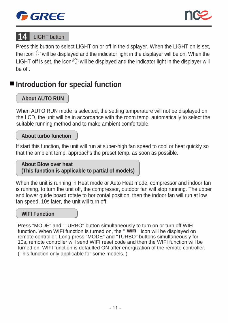
14Press this button to select LIGHT on or off in the displayer. When the LIGHT on is set,the icon will be displayed and the indicator light in the displayer will be on. When theLIGHT off is set, the icon will be displayed and the indicator light in the displayer willbe off.
LIGHT button
About AUTO RUN
When AUTO RUN mode is selected, the setting temperature will not be displayed on
About turbo function
WIFI Function
If start this function, the unit will run at super-high fan speed to cool or heat quickly so
About Blow over heat(This function is applicable to partial of models)
When the unit is running in Heat mode or Auto Heat mode, compressor and indoor fan is running, to turn the unit off, the compressor, outdoor fan will stop running. The upperand lower guide board rotate to horizontal position, then the indoor fan will run at lowfan speed, 10s later, the unit will turn off.
that the ambient temp. approachs the preset temp. as soon as possible.
the LCD, the unit will be in accordance with the room temp. automatically to select thesuitable running method and to make ambient comfortable.
Press "MODE" and "TURBO" button simultaneously to turn on or turn off WIFI function. When WIFI function is turned on, the " " icon will be displayed on remote controller; Long press "MODE" and "TURBO" buttons simultaneously for 10s, remote controller will send WIFI reset code and then the WIFI function will be turned on. WIFI function is defaulted ON after energization of the remote controller.(This function only applicable for some models. )
LED
TIMER ON
LED
TIMER ON
LIGHT
- 12 -
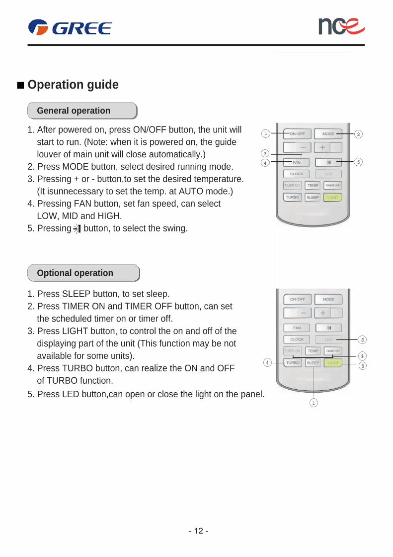
General operation
1. After powered on, press ON/OFF button, the unit will
Optional operation
1. Press SLEEP button, to set sleep.2. Press TIMER ON and TIMER OFF button, can set
3. Press LIGHT button, to control the on and off of the
4. Press TURBO button, can realize the ON and OFF
5. Press LED button,can open or close the light on the panel.
start to run. (Note: when it is powered on, the guide
2. Press MODE button, select desired running mode.3. Pressing + or - button,to set the desired temperature.
4. Pressing FAN button, set fan speed, can select
5. Pressing button, to select the swing.
louver of main unit will close automatically.)
(It isunnecessary to set the temp. at AUTO mode.)
LOW, MID and HIGH.
the scheduled timer on or timer off.
displaying part of the unit (This function may be notavailable for some units).
of TURBO function.
Operation guide
LIGHT
- 13 -
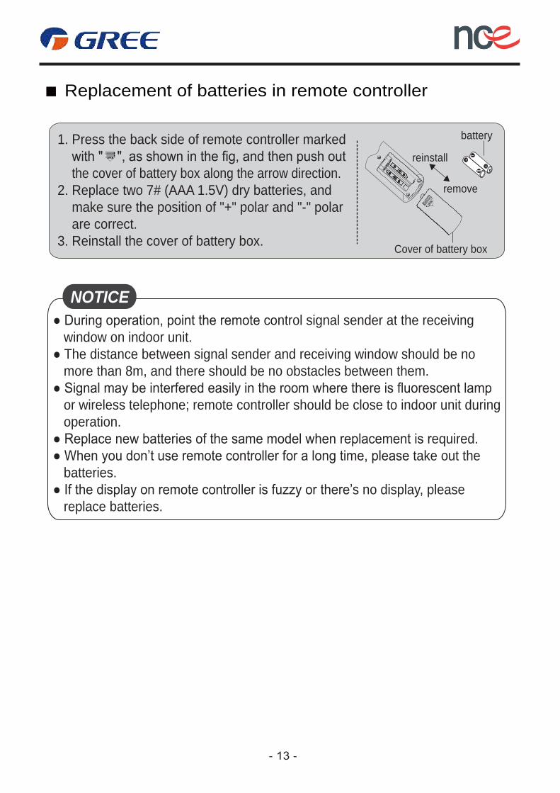
1. Press the back side of remote controller marked
the cover of battery box along the arrow direction.2. Replace two 7# (AAA 1.5V) dry batteries, and make sure the position of "+" polar and "-" polar are correct.3. Reinstall the cover of battery box.
battery
Cover of battery box
remove
reinstall
● During operation, point the remote control signal sender at the receiving window on indoor unit.● The distance between signal sender and receiving window should be no more than 8m, and there should be no obstacles between them.
or wireless telephone; remote controller should be close to indoor unit during operation.● Replace new batteries of the same model when replacement is required.● When you don’t use remote controller for a long time, please take out the batteries.● If the display on remote controller is fuzzy or there’s no display, please replace batteries.
NOTICE
Replacement of batteries in remote controller
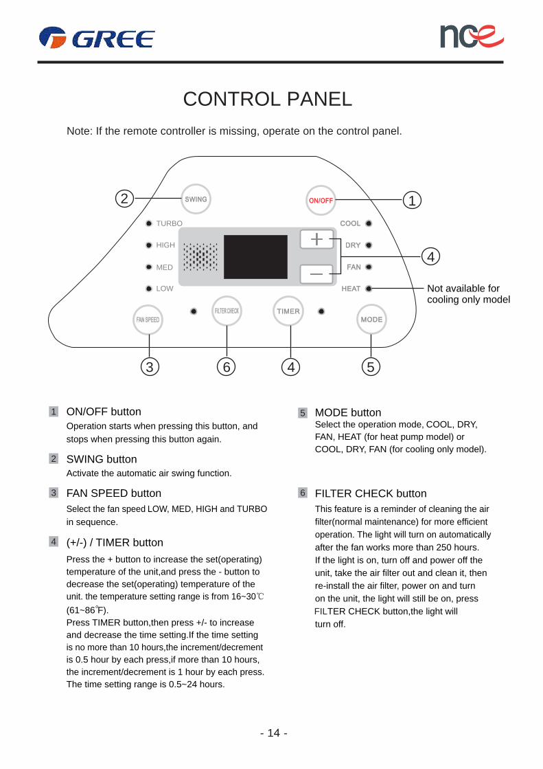
CONTROL PANEL Note: If the remote controller is missing, operate on the control panel.
1 ON/OFF buttonOperation starts when pressing this button, and stops when pressing this button again.
2 SWING button Activate the automatic air swing function.
3 FAN SPEED button Select the fan speed LOW, MED, HIGH and TURBO in sequence.
6 FILTER CHECK button This feature is a reminder of cleaning the air filter(normal maintenance) for more efficient operation. The light will turn on automaticallyafter the fan works more than 250 hours.If the light is on, turn off and power off the unit, take the air filter out and clean it, thenre-install the air filter, power on and turnon the unit, the light will still be on, pressFILTER CHECK button,the light will turn off.
4 (+/-) / TIMER button Press the + button to increase the set(operating)temperature of the unit,and press the - button todecrease the set(operating) temperature of the unit. the temperature setting range is from 16~30℃
Press TIMER button,then press +/- to increase and decrease the time setting.If the time setting is no more than 10 hours,the increment/decrement is 0.5 hour by each press,if more than 10 hours,the increment/decrement is 1 hour by each press.The time setting range is 0.5~24 hours.
o(61~86 F).
- 14 -
5 MODE button Select the operation mode, COOL, DRY, FAN, HEAT (for heat pump model) or COOL, DRY, FAN (for cooling only model).
3 46
2 1
4
5
Not available forcooling only model
TURBO
HIGH
MED
LOW
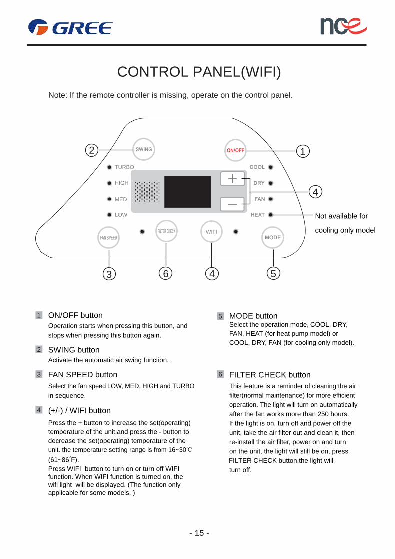
CONTROL PANEL(WIFI) Note: If the remote controller is missing, operate on the control panel.
Not available for
cooling only model
1 ON/OFF buttonOperation starts when pressing this button, and stops when pressing this button again.
2 SWING button Activate the automatic air swing function.
3 FAN SPEED button Select the fan speed LOW, MED, HIGH and TURBO in sequence.
6 FILTER CHECK button This feature is a reminder of cleaning the air filter(normal maintenance) for more efficient operation. The light will turn on automaticallyafter the fan works more than 250 hours.If the light is on, turn off and power off the unit, take the air filter out and clean it, thenre-install the air filter, power on and turnon the unit, the light will still be on, pressFILTER CHECK button,the light will turn off.
4 (+/-) / WIFI button Press the + button to increase the set(operating)temperature of the unit,and press the - button todecrease the set(operating) temperature of the unit. the temperature setting range is from 16~30℃
Press WIFI button to turn on or turn off WIFI function. When WIFI function is turned on, thewifi light will be displayed. (The function onlyapplicable for some models. )
o(61~86 F).
- 15 -
5 MODE button Select the operation mode, COOL, DRY, FAN, HEAT (for heat pump model) or COOL, DRY, FAN (for cooling only model).
TURBO
HIGH
MED
LOW
WIFI
2 1
3 46 5
4
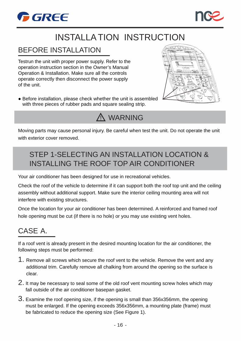
INSTALLA TION INSTRUCTIONBEFORE INSTALLATIONTestrun the unit with proper power supply. Refer to the operation instruction section in the Owner’s Manual Operation & Installation. Make sure all the controls operate correctly then disconnect the power supply of the unit.
WARNING!
Moving parts may cause personal injury. Be careful when test the unit. Do not operate the unit with exterior cover removed.
STEP 1-SELECTING AN INSTALLATION LOCATION & INSTALLING THE ROOF TOP AIR CONDITIONER
Your air conditioner has been designed for use in recreational vehicles.
Check the roof of the vehicle to determine if it can support both the roof top unit and the ceiling assembly without additional support. Make sure the interior ceiling mounting area will not interfere with existing structures.
Once the location for your air conditioner has been determined. A reinforced and framed roof hole opening must be cut (if there is no hole) or you may use existing vent holes.
CASE A.If a roof vent is already present in the desired mounting location for the air conditioner, the following steps must be performed:
1. Remove all screws which secure the roof vent to the vehicle. Remove the vent and any additional trim. Carefully remove all chalking from around the opening so the surface is clear.
2. It may be necessary to seal some of the old roof vent mounting screw holes which mayfall outside of the air conditioner basepan gasket.
3. Examine the roof opening size, if the opening is small than 356x356mm, the opening must be enlarged. If the opening exceeds 356x356mm, a mounting plate (frame) must be fabricated to reduce the opening size (See Figure 1).
- 16 -
● Before installation, please check whether the unit is assembledwith three pieces of rubber pads and square sealing strip.
356
356
19
25Figure 1
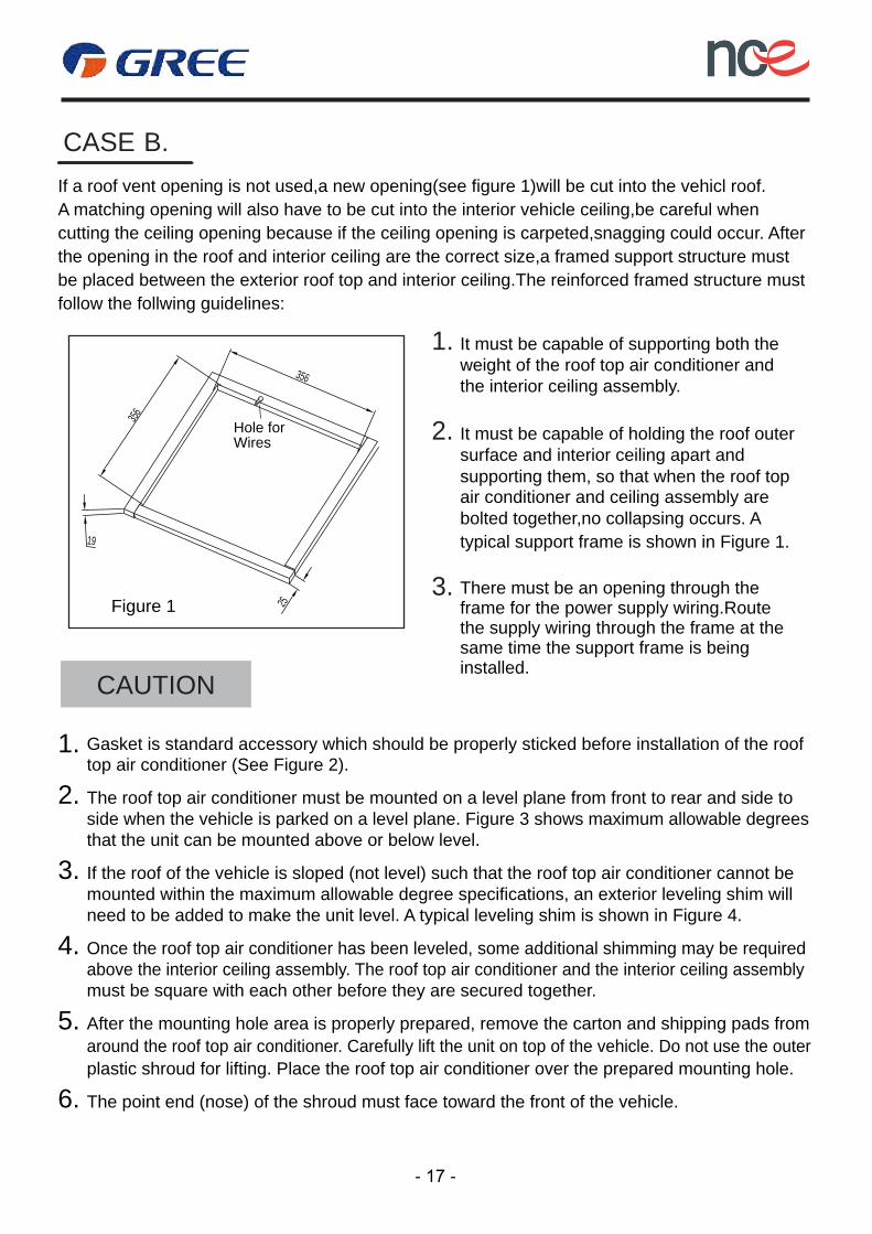
If a roof vent opening is not used,a new opening(see figure 1)will be cut into the vehicl roof.A matching opening will also have to be cut into the interior vehicle ceiling,be careful when cutting the ceiling opening because if the ceiling opening is carpeted,snagging could occur. After the opening in the roof and interior ceiling are the correct size,a framed support structure must be placed between the exterior roof top and interior ceiling.The reinforced framed structure must follow the follwing guidelines:
1. It must be capable of supporting both the weight of the roof top air conditioner and the interior ceiling assembly.
3. There must be an opening through theframe for the power supply wiring.Routethe supply wiring through the frame at thesame time the support frame is beinginstalled.
2. It must be capable of holding the roof outer surface and interior ceiling apart and supporting them, so that when the roof topair conditioner and ceiling assembly are bolted together,no collapsing occurs. A typical support frame is shown in Figure 1.
CAUTION
2. The roof top air conditioner must be mounted on a level plane from front to rear and side to side when the vehicle is parked on a level plane. Figure 3 shows maximum allowable degrees that the unit can be mounted above or below level.
3. If the roof of the vehicle is sloped (not level) such that the roof top air conditioner cannot bemounted within the maximum allowable degree specifications, an exterior leveling shim will need to be added to make the unit level. A typical leveling shim is shown in Figure 4.
4. Once the roof top air conditioner has been leveled, some additional shimming may be required above the interior ceiling assembly. The roof top air conditioner and the interior ceiling assembly must be square with each other before they are secured together.
5. After the mounting hole area is properly prepared, remove the carton and shipping pads from around the roof top air conditioner. Carefully lift the unit on top of the vehicle. Do not use the outerplastic shroud for lifting. Place the roof top air conditioner over the prepared mounting hole.
6. The point end (nose) of the shroud must face toward the front of the vehicle.
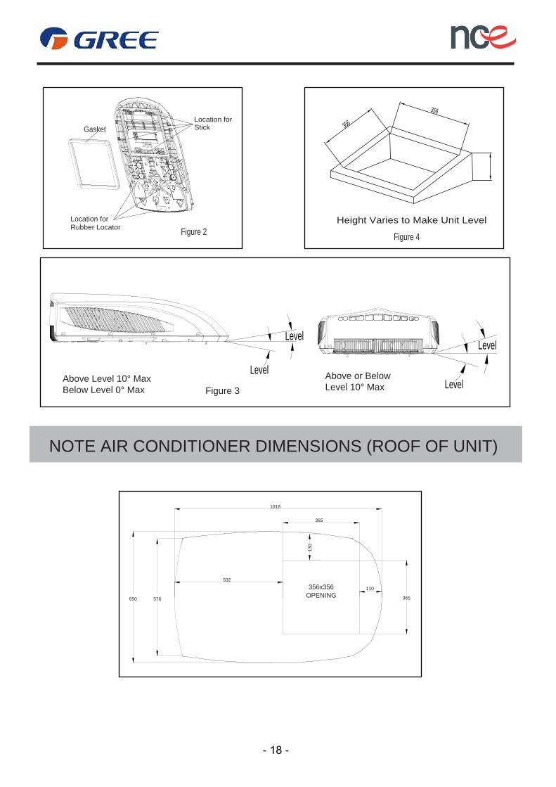
1. Gasket is standard accessory which should be properly sticked before installation of the roof top air conditioner (See Figure 2).
Hole forWires
CASE B.
- 17 -
356
356
NOTE AIR CONDITIONER DIMENSIONS (ROOF OF UNIT)
Above or Below Level 10° Max
Level
Above Level 10° Max Below Level 0° Max Figure 3 Level
Height Varies to Make Unit Level
Figure 4
1018
356x356OPENING
GasketLocation for
Location for Rubber Locator
Stick
- 18 -
Figure 2
Level
Level
365
130
532
650 576
110
365
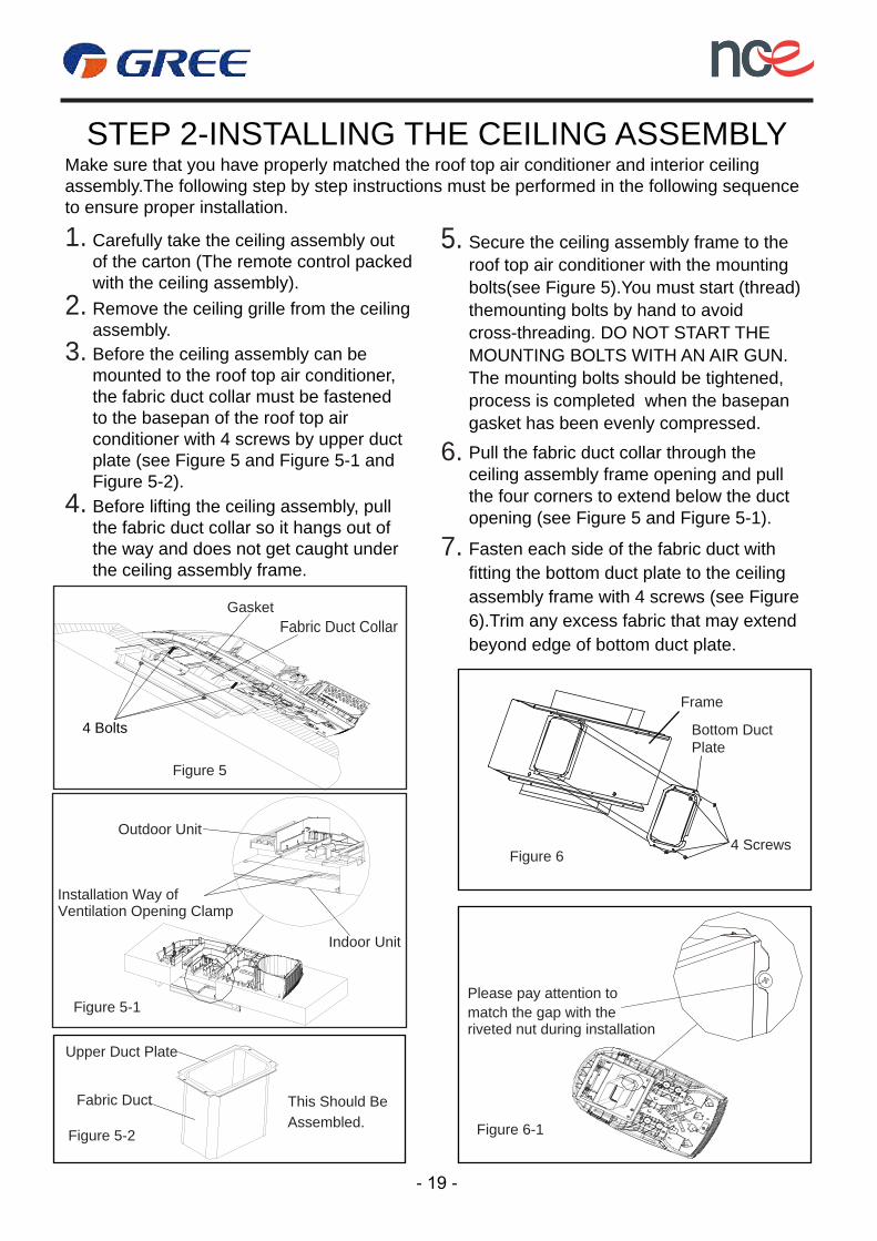
STEP 2-INSTALLING THE CEILING ASSEMBLYMake sure that you have properly matched the roof top air conditioner and interior ceiling assembly.The following step by step instructions must be performed in the following sequenceto ensure proper installation.
2. Remove the ceiling grille from the ceilingassembly.
4. Before lifting the ceiling assembly, pullthe fabric duct collar so it hangs out ofthe way and does not get caught underthe ceiling assembly frame.
1. Carefully take the ceiling assembly out
with the ceiling assembly).of the carton (The remote control packed
3.mounted to the roof top air conditioner,
plate (see Figure 5 and Figure 5-1 and Figure 5-2).
Before the ceiling assembly can be
to the basepan of the roof top airthe fabric duct collar must be fastened
conditioner with 4 screws by upper duct
5. Secure the ceiling assembly frame to the
gasket has been evenly compressed.
roof top air conditioner with the mountingbolts(see Figure 5).You must start (thread)themounting bolts by hand to avoidcross-threading. DO NOT START THE MOUNTING BOLTS WITH AN AIR GUN.The mounting bolts should be tightened,process is completed when the basepan
6.
opening (see Figure 5 and Figure 5-1).
Pull the fabric duct collar through the
the four corners to extend below the ductceiling assembly frame opening and pull
7.
6).Trim any excess fabric that may extend beyond edge of bottom duct plate.
Fasten each side of the fabric duct withfitting the bottom duct plate to the ceiling assembly frame with 4 screws (see Figure
4 ScrewsFigure 6
Frame
Bottom Duct Plate
Figure 6-1
Please pay attention tomatch the gap with theriveted nut during installation
Upper Duct Plate
Fabric Duct
Figure 5-2
Figure 5-1
This Should BeAssembled.
Installation Way ofVentilation Opening Clamp
Indoor Unit
Outdoor Unit
4 Bolts
Figure 5
GasketFabric Duct Collar
- 19 -
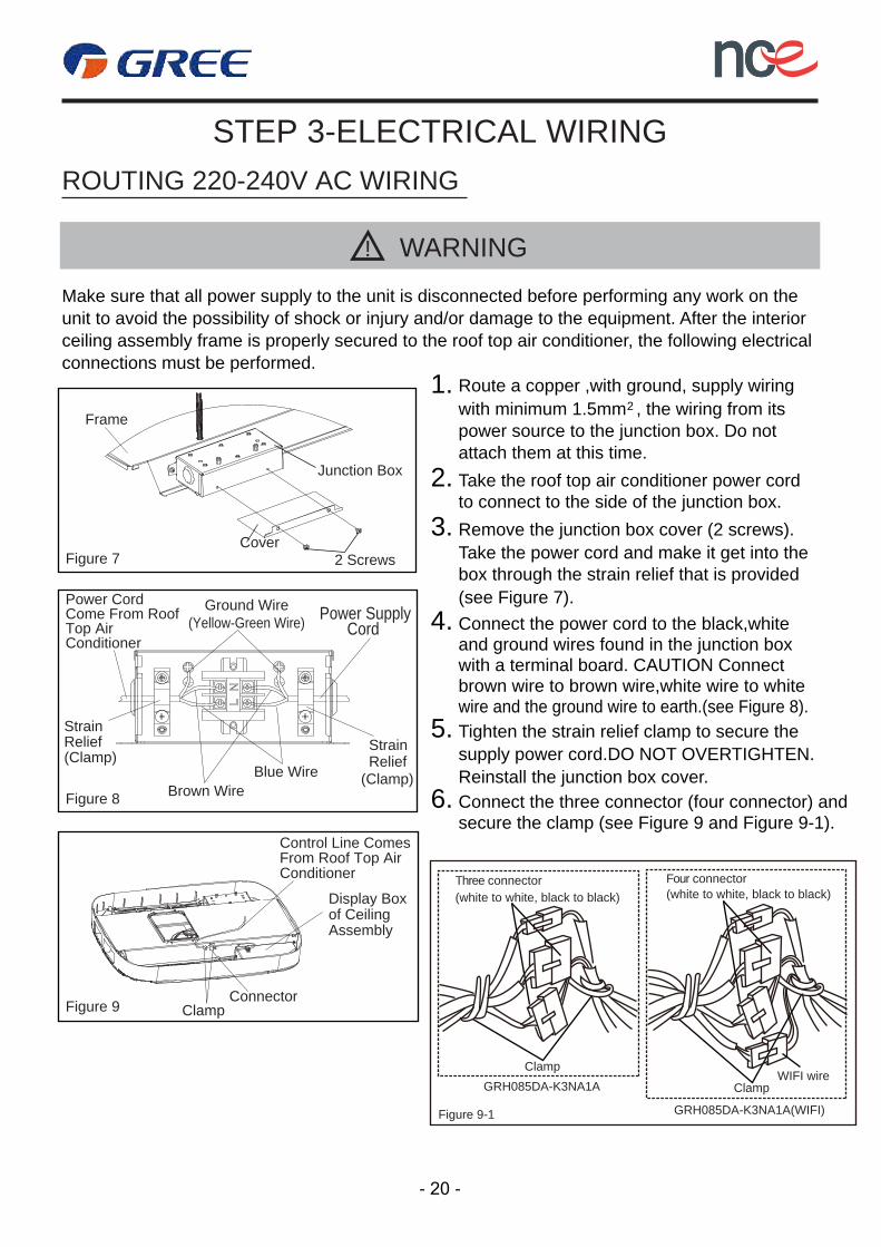
STEP 3-ELECTRICAL WIRINGROUTING 220-240V AC WIRING
! WARNING
Make sure that all power supply to the unit is disconnected before performing any work on the unit to avoid the possibility of shock or injury and/or damage to the equipment. After the interiorceiling assembly frame is properly secured to the roof top air conditioner, the following electricalconnections must be performed.
Figure 7 2 Screws
Come From Roof Power Cord Ground Wire
(Yellow-Green Wire) Top Air Power Supply
Cord Conditioner
StrainRelief (Clamp)
StrainRelief
(Clamp)Brown Wire
Blue Wire
Figure 8
Control Line Comes From Roof Top Air Conditioner
Display Box of Ceiling Assembly
ConnectorClampFigure 9
2. Take the roof top air conditioner power cordto connect to the side of the junction box.
3. Remove the junction box cover (2 screws).Take the power cord and make it get into the box through the strain relief that is provided(see Figure 7).
4. Connect the power cord to the black,white and ground wires found in the junction box with a terminal board. CAUTION Connect brown wire to brown wire,white wire to white wire and the ground wire to earth.(see Figure 8).
5. Tighten the strain relief clamp to secure the supply power cord.DO NOT OVERTIGHTEN.Reinstall the junction box cover.
Frame
Junction Box
Cover
6. Connect the three connector (four connector) andsecure the clamp (see Figure 9 and Figure 9-1).
- 20 -
1. Route a copper ,with ground, supply wiring with minimum 1.5mm , the wiring from its power source to the junction box. Do notattach them at this time.
2
Clamp
Three connector(white to white, black to black)
Figure 9-1
GRH085DA-K3NA1A
GRH085DA-K3NA1A(WIFI)
ClampWIFI wire
Four connector(white to white, black to black)
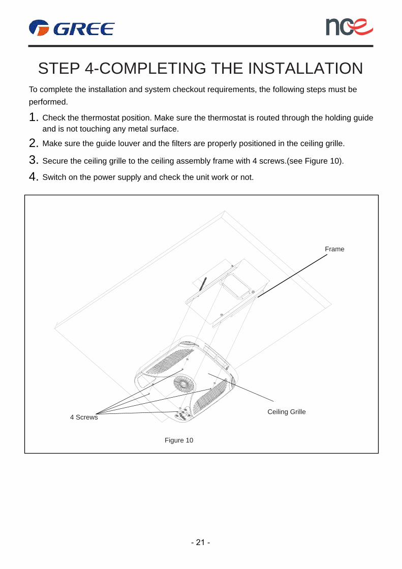
Make sure the guide louver and the filters are properly positioned in the ceiling grille. 2.Secure the ceiling grille to the ceiling assembly frame with 4 screws.(see Figure 10).3.Switch on the power supply and check the unit work or not. 4.
Check the thermostat position. Make sure the thermostat is routed through the holding guideand is not touching any metal surface.
1.
STEP 4-COMPLETING THE INSTALLATIONTo complete the installation and system checkout requirements, the following steps must beperformed.
Frame
Ceiling Grille4 Screws
Figure 10
- 21 -
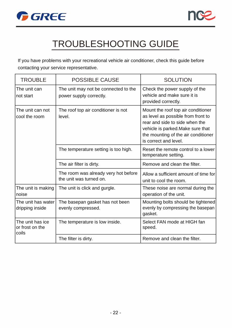
TROUBLESHOOTING GUIDEIf you have problems with your recreational vehicle air conditioner, check this guide beforecontacting your service representative.
TROUBLE SOLUTIONPOSSIBLE CAUSEThe unit can not start
The unit may not be connected to the power supply correctly.
Check the power supply of the vehicle and make sure it is provided correctly.
The unit can not cool the room
The roof top air conditioner is notlevel.
The temperature setting is too high.
The air filter is dirty.
Mount the roof top air conditioneras level as possible from front torear and side to side when the vehicle is parked.Make sure thatthe mounting of the air conditioner is correct and level.
Reset the remote control to a lowertemperature setting.
Remove and clean the filter.
Allow a sufficient amount of time forunit to cool the room.
Mounting bolts should be tightenedevenly by compressing the basepangasket.
The filter is dirty. Remove and clean the filter.
The unit is making
The room was already very hot before
The unit is click and gurgle.
The basepan gasket has not beenevenly compressed.
The temperature is low inside.
the unit was turned on.
noiseThe unit has waterdripping inside
The unit has iceor frost on the coils
Select FAN mode at HIGH fan
These noise are normal during theoperation of the unit.
speed.
- 22 -

NORMAL MAINTENANCE PROCEDURES
ACTIVETY FREQUENCY
Twice a year.Remove the cover and wash the condenser coil
Clean the filter(More frequent cleaning may be necessary light on.depending on the air quality)
When the air conditioner FILTER CHECK
HOW TO REMOVE THE AIR FILTER
Remove the air filters by pulling them as illustrated below.
HOW TO CLEAN THE AIR FILTER
WARNING!
FAILURE TO FOLLOWING INSTRUCTIONS COULD RESULT IN SERIOUS PERSONAL INJURY
2. Be careful when you maintain the refrigeration system, which has the high internal pressure.
3. Do not block the filter and the indoor air inlet badly to prevent water leakage.
1. Don’t touch the capacitor terminals without the electric discharge, the capacitor still may havethe high voltage even though the power supply is turned off.
Wash away dust from the air filters with clean water or vacuum the filter with an electric household vacuum cleaner.
- 23 -