owner s manual - d1qkyo3pi1c9bx.cloudfront.net odyssey home gym note: due to continuing product...
TRANSCRIPT
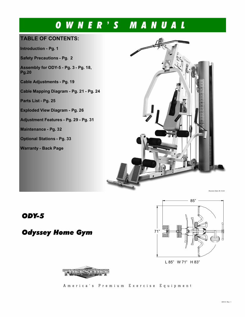
ODY-5
Odyssey Home Gym
ODY-5 Rev. 1
L 85” W 71” H 83”
O W N E R ’ S M A N U A LTABLE OF CONTENTS:
Introduction - Pg. 1
Safety Precautions - Pg. 2
Assembly for ODY-5 - Pg. 3 - Pg. 18,Pg.20
Cable Adjustments - Pg. 19
Cable Mapping Diagram - Pg. 21 - Pg. 24
Parts List - Pg. 25
Exploded View Diagram - Pg. 26
Adjustment Features - Pg. 29 - Pg. 31
Maintenance - Pg. 32
Optional Stations - Pg. 33
Warranty - Back Page
Revision Date 05- 10-00
A m e r i c a ’ s P r e m i u m E x e r c i s e E q u i p m e n t
71”
85”

About the Odyssey 5 Home Gym (ODY-5)
Congratulations on your new purchase of the Odyssey 5 HomeGym (ODY-5). This gym is capable of a variety of differentexercises, as well as, smooth and user-friendly adjustmentfeatures. In addition, this gym has been designed to meet theneeds and performance requirements for a suitable home exercise machine. We hope you are completely satisfied with this product and wish you many years of enjoyment.
Tuff Stuff Equipment
This Tuffstuff product has been built to precise quality standards and has been carefully packaged to ensure that damage will not occur during shipment. The Home Lifetime Warranty and signatureindicating final inspection has been conducted by our line foreman, is an expression of our confidence in the completeness, thematerials, and workmanship of this product.
Warranty
SEE A COPY OF WARRANTY ON BACK PAGE.
Registration Card
To avoid unnecessary delays in warranty service and to insure that a permanent record of your purchase is on file with our factory, be sure to complete the warranty registration card and send it to Task Industries today.
A Note provides information necessary to properlycomplete a procedure or information which will make the procedure easier to understand.
A Caution provides a special procedure or specialsteps which must be taken while completing theprocedure where the Caution is found. Not following a Caution can result in damage to the equipment.
A Warning provides a special procedure or specialsteps which must be taken while completing theprocedure where the Warning is found . Not following a Warning can result in personal injury.
Assembly Notes
1. Read and follow each step of this Assembly Instruction Manual in sequence. Do not skip ahead, as it will result in an improperassembly or in having to disassemble parts later.
2. During the assembly of this unit you will be instructed to leave some Hex Head Cap Screws loosely fastened. Naturally, they will be fully fastened later in the assembly process. This is done to prevent any difficulty with alignment of some parts during this assembly.
Loosely Fasten provides a instruction to looselyfasten (ex: hand tighten) a hardware assembly only. This instruction is intended for the alignment ofhardware components during the assembly process.
Fully Fasten provides a instruction to fully fasten (ex: completely tighten) a hardware assembly.
Hardware Measurement Diagram
1
About the IconsThe icons displayed in this Owner’s Manual are used to facilitate the correct assembly and safe use of this Product, as-well-as to prevent injury to yourself or anyone else.
LOOSELY FASTEN
F U L L Y F A S T E N
Introduction
This will notify you of lifting heavy components. It is advisable to lift with your legs, not with your back, to avoid a possible back injury.
WARNING
ODY-5 Odyssey Home Gym
Note: Due to continuing product improvements, specifications and designs are subject to changewithout notice.
Even though we have prepared this manual with extreme care, neither the publisher nor the author can accept responsibility for any errors in, or omission from, the information given.
Prior to the Assembly of the ODY-5
1. We advise you to consult your local Tuff Stuff retailer if youshould have a question or problem regarding the properassembly of this Odyssey 5 Home Gym (ODY-5).
2. Consider the complete surface area of the ODY-5. Use theoverhead view on the front page for designing your layout before assembling. Once the ODY-5 has been fully assembled it will be heavy and difficult to move, therefore you should assemble the ODY-5 in the area where it is to be used upon completion.
3. It is recommended that another person assist you with theassembly this unit.
4. Neatly organize and identify all parts according to the Parts List on page 25 and the Exploded View Diagram on page 24.
Tool Requirements1. One 9/16” combination wrench2. One 3/4” combination wrench3. One 7/8” combination wrench4. Two 7/16” combination wrenches5. One 1/2” combination wrench6. One ratchet7. One 9/16” socket8. One 3/4” socket9. One rubber mallet
10. External retaining-ring pliers 11. Windex or household glass cleaner12. One can silicone spray/ teflon spray lubricant13. Multi-purpose grease14. Measuring tape15. Masking tape16. Utility knife
Specifications
1. Maximum Wt. Capacity - 200 Lbs. Fixed2. Total Machine Weight - 475 Lbs.3. Footprint (LWH) - See Front Cover

SafetyFirst
Regardless of how enthusiastic you may be about getting onyour equipment and exercising, take the time to ensure that your safety is not jeopardized. A moment’s lack of attention can result in an accident, as can failure to observe certain simple safetyprecautions.
1. Read, study and understand the Owner’s Manual and all the warning labels on this product. Furthermore, it isrecommended to familiarize yourself and others with theproper operation and workout recommendations for this Tuff Stuff product prior to use. Some of this information can beobtained in this Owner’s Manual, as well as from your localTuff Stuff retailer.
2. It is imperative that you retain this Owner’s Manual and be sure all warning labels are legible and intact. ReplacementOwner’s Manuals and labels are available from your local Tuff Stuff retailer.
3. Consult with your physician before beginning any exerciseprogram.
4. Use proper discretion when children are present.
5. Frayed or worn cables can be dangerous and may causeinjury. Periodically check these cables for any indication ofwear.
6. Keep hands, limbs, loose clothing and long hair well out of the
way of moving parts.
7. Do not attempt to lift more weight than you can control safely.
8. Inspect the Odyssey Home Gym for any sign of wear on parts, hardware becoming loose or cracks on welds. If a problem is found do not use or allow the machine to be used until defective part is repaired or replaced.
9. Pay special attention to the Push Pull Pins (#53 and #54)located on Press Bar Selector Housing (#17), Front Upright (#3) and Leg Extension Bench Frame (#11). See Fig.1. Be sure they are fully engaged into the selectorized holes. Referto Fig. 2 for further illustration of this warning.
Safety Precautions
Fig. 1 Illustration above depicts the location of the Push Pull Pins1/2” Special (#53) and Push Pull Pin 1/2” (#54) on this unit.
Push Pull Pin1/2” Special (#82)
Push Pull Pin1/2” (#62)
ODY-5 Odyssey Home Gym 2
Push Pull Pin1/2” Special (#82)
Fig. 2 Warning: Check that all Push Pull Pins 1/2” (#53, #54) are fully engaged into the selectorized holes.
Push Pull PinFully Engaged
Push-Pull Pin 1/2” Special (#53)
Push-Pull Pin 1/2”Special (#53)
Push-Pull Pin 1/2” (#54)

FIG. 4 Next, attach three Nylon Pulleys 4 1/2 Rd (#64-Labeled L,W,M) to the pulley brackets on the Base Frame (#2) and secure them into place using three Hex Head Cap Screws 3/8-16 X 1 3/4 (#93), six Flat Washers SAE 3/8” (#71) and three Nylon Insert Jam Lock Nuts 3/8-16 (#82).
FIG. 3 On a flat surface, lay the Base Frame (#2) down and insert two Plastic End Caps 2” Sq. (#66) into the tube-ends of the Base Frame (#2),as labeled above. Next, attach two Nylon Pulleys 4 1/2 Rd (#64-LabeledU, S) to the Base Frame (#2) and secure them into place using two Hex Head Cap Screws 3/8-16 X 2 (#99), four Flat Washers SAE 3/8” (#71) and two Nylon Insert Jam Lock Nuts 3/8-16 (#82).
Note:The black boxed letters pointing to the pulleys are usedthroughout this manual as reference to the Cable MappingDiagram on pages 21-24. These black boxed letters will beprimarily used for locating certain pulleys during the cable routing process beginning with Fig. 31.
FIG. 5 Next, locate the Low Row Stabilizer (#14) and insert it into the receptacle on the Base Frame (#2). Secure it into place using one Hex Head Cap Screw 3/8-16 X 3 (#90), two Flat Washers SAE 3/8” (#71) and one Nylon Insert Jam Nut 3/8-16 (#82). Next, insert two Plastic Insert Caps 1” Rd. (#98) into the tube-ends of the Low Row Stabilizer (#14), as labeled above.
Loosely Fasten: Do not completely fasten this hardwareassembly at this time, as it will be completely fastened later in Fig.
10 on the next page.
FIG. 6 Next, attach the Low Row Foot Support (#15) to the Low Row Stabilizer (#14) and secure it into place using one Foot Roll Tube1X16 (#31). Using the supplied Hex Key 3/16 (#108), secure the FootRoll Tube 1X16 (#31) into place using one Set Screw 3/8-16 X 1/2 (#47),as shown in caption above. Be sure the Foot Roll Tube 1X16 (#31) is flush on each end after inserted into the Low Row Foot Support (#15).Next, insert two Plastic Insert Caps 1” Rd. (#98) into the tube-ends of the Foot Roll Tube 1X16 (#31).
LOOSELY FASTEN
3 ODY-5 Odyssey Home Gym

FIG. 8 Next, attach the Front Upright (#3) to the Base Frame (#2), in the position as shown above, and secure it into place using one Hex Head Cap Screw 3/8-16 X 2 3/4 (#91), two Flat Washers SAE 3/8” (#71) and one Nylon Insert Jam Lock Nut 3/8-16 (#82). Next, insert one Plastic Insert Cap 2” Sq. (#66) into the tube-end of the Front Upright (#3).
Loosely Fasten: Do not completely fasten this hardwareassembly at this time, as it will be completely fastened later in the
assembly process.
FIG. 7 Next, insert two Plastic End Caps 2” Sq. w/Groove (#65) onto each tube-end of the Rear Upright (#4), as shown above. Next, attach the Rear Upright (#4) to the Base Frame (#2) and secure it into place, as shown in caption above, using one Support Plate 1/4 X 2 X 5 (#32), twoHex Head Cap Screws 3/8-16 X 3 1/4 (#89), four Flat Washers SAE3/8” (#71) and two Nylon Insert Lock Nuts 3/8-16 (#81).
Loosely Fasten: Do not completely fasten this hardwareassembly at this time, as it will be completely fastened later in the
assembly process.
FIG. 9 Next, attach a Nylon Pulley 4 1/2 Rd. (#64- Labeled D) to the pulley plate located on the Front Upright (#3) and secure it into place using one Cable Retainer Bracket L-Shaped (#28), one Hex Head Cap Screw 3/8-16 X 1 3/4 (#93), two Flat Washers SAE 3/8” (#71) and one Nylon Insert Jam Lock Nut 3/8-16 (#82). Refer to the Exploded ViewDiagram on page 26 for further illustration of this assembly.
Note: Be sure to position the Cable Retainer Bracket L-Shaped(#28) as shown in caption above.
Next, attach two Nylon Pulleys 4 1/2 Rd. (#64-Labeled F,R) into the pulley brackets located on the Front Upright (#3) and secure them into place using two Hex Head Cap Screws 3/8-16 X 2 1/2 (#92), four Flat Washers SAE 3/8” (#71) and two Nylon Insert Jam Lock Nuts 3/8-16 (#82).
Owner’s Manual: Assembly Instructions
LOOSELY FASTEN
LOOSELY FASTEN
FIG. 10 Next, locate the Leg Extension Bench Frame (#11) and secure it to the Front Upright (#3), as shown above, using one Hex HeadCap Screw 3/8-16 X 2 3/4 (#91), two Flat Washers SAE 3/8” (#71) and one Nylon Insert Jam Lock Nut 3/8-16 (#82). Locate the Stabilizer14” (#29) and insert one Plastic End Cap 2” Sq. w/Groove (#65) into the tube-end. Secure the other end of the Leg Extension Bench Frame(#11) to the Base Frame (#2) and the Stabilizer 14” (#29) using one Hex Head Cap Screws 3/8-16 X 5 (#86), two Flat Washers SAE 3/8” (#71) and one Nylon Insert Lock Nut 3/8-16 (#81). Next, secure the other end of the Stabilizer 14” (#29) to the Base Frame (#2) using one Hex Head Cap Screw 3/8-16 X 3 (#90), two Flat Washers SAE 3/8” (#71) and one Nylon Insert Lock Nut 3/8-16 (#81). Next, insert one Plastic Insert Cap 2” Sq. (#66) into the tube-end of the Leg Extension Bench Frame (#11).
Loosely Fasten: Do not completely fasten this hardwareassembly at this time, as it will be completely fastened later in the
assembly process.LOOSELY FASTEN
ODY-5 Odyssey Home Gym 4

FIG. 11 Next, attach the Leg Extension Arm (#12), in the position as shown, to the Leg Extension Bench Frame (#11) and secure it into place using one Leg Extension Axle 1/2 X 2 1/2 (#9). Next, secure theLeg Extension Axle 1/2 X 2 1/2 (#9) into place using two Set Screws 1/4-20 X 3/8 (#48), as shown in caption above. Use the supplied Hex Key Long 1/8 (#109) for fastening these Set Screws 1/4-20 X 3/8 (#48). Next,insert one Plastic Insert Cap 1 1/2 Sq. (#67) into the tube-end of the LegExtension Arm (#12).
Note: It is recommended to grease the Leg Extension Axle 1/2 X 2 1/2 (#9) with multi-purpose grease prior to assembling.
FIG. 12 Attach the Top Pulley Assembly (#5), in the position asshown, to the Front Upright (#3) and secure it into place using two Hex Head Cap Screws 3/8-16 X 4 1/4 (#88), four Flat Washers SAE 3/8” (#71) and two Nylon Insert Lock Nuts 3/8-16 (#81).
Loosely Fasten: Do not completely fasten this hardwareassembly at this time, as it will be completely fastened later in the
assembly process.LOOSELY FASTEN
FIG. 14 Next, attach two Nylon Pulleys 4 1/2 Rd. (#64-Labeled A,B) into the pulley brackets located on the Top Pulley Assembly (#5) and secure them into place using two Hex Head Cap Screws 3/8-16 X 2 1/2 (#92), four Flat Washers SAE 3/8” (#71) and two Nylon Insert Jam Lock Nuts 3/8-16 (#82). Next, attach four Nylon Pulleys 4 1/2 Rd. (#64-Labeled P,G,N,H) into the pulley brackets located on the Top PulleyAssembly (#5) and secure them into place using two Hex Head Cap Screws 3/8-16 X 2 3/4 (#91), four Flat Washers SAE 3/8” (#71) and two Nylon Insert Jam Lock Nuts 3/8-16 (#82).
FIG. 13 Next, attach the Top Pulley Assembly (#5) to the RearUpright (#4) and secure it into place using two Hex Head Cap Screws3/8-16 X 3 1/4 (#89), four Flat Washers SAE 3/8” (#71) and two Nylon Insert Lock Nut 3/8-16 (#81). Next, insert one Plastic Insert Cap 2” Sq. (#66) into the tube-end on the Rear Upright (#4).
Fully Fasten: Proceed to align and fully fasten this hardware as-sembly and all the previous assemblies that were left loosely fas-tened.
FULLY FASTEN
5 ODY-5 Odyssey Home Gym

FIG. 15 Next, attach Lat Bar Holder 2 X 3 (#19), in the position as shown above, to the Top Pulley Assembly (#5) and secure it into place using one Hex Head Cap Screw 3/8-16 X 2 3/4 (#91), two Flat Washers SAE 3/8” (#71) and one Nylon Insert Jam Lock Nut 3/8-16 (#82).
FIG. 17 Next, insert the Press Bar (#1) up into the Press BarSelector Housing (#17) and support in into place using the push-pull pin (#53-Not Shown). Next, using a rubber mallet, insert the Pivot Axle 1 X 8 1/8 (#18) into the Press Bar Selector Housing (#17) and through the Press Bar (#1). Refer to Fig. 67 on page 27 for further clarification of this assembly.
Note: It is recommended to grease the Pivot Axle 1 X 8 1/8 (#18)with multi-purpose grease prior to assembling.
FIG. 16 Attach the Press Bar Selector Housing (#17) to the TopPulley Assembly (#5), as shown above. Using a rubber mallet, insertthe Pivot Axle 1 X 8 1/8 (#18) through the holes in the Press Bar Selector Housing (#17) and through the receptacle on the Top Pulley Housing (#5) until it is flush with both sides. Refer to Fig. 67 on page 27for further clarification of this assembly.
Note: It is recommended to grease the Pivot Axle 1 X 8 1/8 (#18) with multi-purpose grease prior to assembling. Also, the fourPlastic Insert Caps 2” Sq. (#66) located in the tube-ends ofthe Press Bar Selector Housing (#17) have been pre-assembledby the factory.
FIG. 18 Next, secure the Press Bar Selector Housing (#17) to the Pivot Axle 1 X 8 1/8 (#18) using two Set Screws 3/8-16 X 1/2 (#47), as shown above. Then, secure into place the Press Bar (#1) to the PivotAxle 1 X 8 1/8 (#18) using two Set Screws 3/8-16 X 1/2 (#47). Use the Supplied Hex Key 3/16 (#108) for securing all four Set Screws 3/8-16 X 1/2 (#108) into the threaded sockets on the Press Bar Selector Housing (#17). Next, apply four 1” Rd. Silver Mylar Decals (#111–Not shown) overthe ends of the Pivot Axles 1 X 8 1/8 (#18). These decals are used to hide and protect the ends of axles.
ODY-5 Odyssey Home Gym 6
Owner’s Manual: Assembly Instructions

FIG. 21 Secure the Left Pec Dec Arm (#7) into place using one Hex Head Cap Screw 3/8-16 X 1 (#95), one Split Washer 3/8” (#76) and one Fender Washer 3/8 X 1 1/2 (#72). Repeat the same procedure for the Right Pec Dec Arm (#6). Refer to the Exploded View Diagram on page 26 for further illustration of this assembly.
FIG. 19 Next, attach two Nylon Pulleys 4 1/2 Rd. (#64-Labeled C,E) to the pulley bracket located on the Press Bar Selector Housing (#17) andsecure them into place using one Hex Head Cap Screw 3/8-16 X 2 3/4 (#91), two Flat Washers SAE 3/8” (#71) and one Nylon Insert Jam Lock Nut 3/8-16 (#82).
FIG. 20 Next, insert the Left Pec Dec Arm (#7), in the position as shown above, into the receptacle on the Front Upright (#3). Repeat the same procedure for the Right Pec Dec Arm (#6). Refer to Fig. 72 on page 28 or the Exploded View Diagram on page 26 for further illustration of this assembly.
Note: It is recommended to grease both axles on the Left andRight Pec Dec Arms (#7,#6) with multi-purpose grease prior to assembling.
FIG. 22 Locate the two Pec Dec Swivel Handles (#8) and organize them on a flat surface, as shown above.
Note: Parts (#47, #50 and #59) have been pre-assembled on the Pec Dec Swivel Handles (#8) by the factory.
7 ODY-5 Odyssey Home Gym

FIG. 24 Next, secure the Pec Dec Swivel Handles (#8) using two Re-taining Snap Rings (#75). If possible, use special snap ring pliers for this job, as shown above. If the tool is not available, carefully work each Re-taining Snap Ring (#75) into the groove, then push up alternately with a screw driver working the Retaining Snap Ring (#75) into the groove.Refer to Fig. 72 on page 28 for further illustration of this assembly.
Note: Be careful not to distort the Retaining Snap Rings (#75) or bend them.
FIG. 26 Insert the two Guide Rods 3/4 X 72 (#21) into the receptacles on the Base Frame (#2), as shown above. Next, insert two RubberDonuts 3/4 X 2 1/2 (#60) onto each Guide Rod 3/4 X 72 (#21).
Note: Lubricate the Guide Rods 3/4 X 72 (#21) with a silcone or teflon lubricant at this time.
FIG. 23 Next, using a rubber mallet, insert a Pec Dec Swivel Handle (#8), in the position as shown above, into the Left Pec Dec Arm (#7). Be sure that the Pec Dec Swivel Handle (#8) has been completely inserted through the receptacle on the Left Pec Dec Arm (#7). Repeat the same procedure for the Right Pec Dec Arm (#6). Refer to Fig. 72 on page 28 for further illustration of this assembly.
FIG. 25 Picture of Retaining Snap Ring (#75) inserting into Pec Dec Swivel Handle (#8).
ODY-5 Odyssey Home Gym 8
Owner’s Manual: Assembly Instructions

FIG. 28 Now slide the Top Plate/Selector Bar (#24) over the GuideRods 3/4 X 72 (#21) allowing it to come to rest on the completed weight stack.
Note: Be sure the label (FRONT SIDE) located on the Top Plate/Selector Bar (#24) is facing toward you before you slide the TopPlate/Selector Bar (#24) over the Guide Rods 3/4 X 72 (#21).
Warning: Do not lift more than you can control safely. Inaddition, do not lift using only your back. It is recommended that when you are lifting, bend your knees and lift slowly with your back straight. Be sure that the weight is distributed over your knees or legs when lifting. Also, it is advisable to wear a well fitted lifting belt during heavy lifting.
FIG. 27 Carefully begin sliding the Weight Plates over the GuideRods 3/4 X 72 (#21), one or two at a time as your skill permits.
Updated: The Weight Stack has been replaced by the Weight Stack illustrated on Fig. 73. Refer to Fig. 73 on page 28 to com-plete this assembly.
Warning: Do not lift more than you can control safely. Inaddition, do not lift using only your back. It is recommended that when you are lifting, bend your knees and lift slowly with your back straight. Be sure that the weight is distributedover your knees or legs when lifting. Also, it is advisable to wear a well fitted lifting belt during heavy lifting.
FIG. 29 Maneuver the two Guide Rods 3/4 X 72 (#21) into the holes on the bottom side of the Guide Rod Retainer Housing (#20). Next,mount the Guide Rod Retainer Housing (#20) along with the two captive Guide Rods 3/4 X 72 (#21) to the side of the Top Pulley Assembly (#5).Secure this assembly using two Hex Head Cap Screws 3/8-16 X 2 3/4 (#91), four Flat Washer SAE 3/8” (#71) and two Nylon Insert Jam Lock Nuts 3/8-16 (#82).
Loosely Fasten: Do not completely fasten this hardwareassembly at this time, as it will be completely fastened later in the
assembly process.
FIG. 30 First, locate the Adjustable Pulley Bracket (#36) and insert one Nylon Pulley 4 1/2 Rd. (#64-Labeled I). Secure the Nylon Pulley 4 1/2 Rd. (#64-Labeled I) into place using one Hex Head Cap Screws 3/8-16 X 1 3/4 (#93), two Flat Washers SAE 3/8” (#71) and one Nylon Insert Jam Lock Nut 3/8-16 (#82). Next, thread one Regular Hex Nut 1/2-13(#80) and insert one Flat Washer SAE 1/2” (#70) over the bolt on the Adjustable Pulley Bracket (#36), as shown above at the left. Second,locate the two Adjustable Stoppers (#33) and thread one Regular Hex Nut 1/2-13 (#80) and insert one Flat Washer SAE 1/2” (#70) over each bolts, as shown above at the middle and right.
LOOSELY FASTEN
9 ODY-5 Odyssey Home Gym
Update: The Weight Stack pictured in this manual differ in shape and appearance to the supplied with this unit.
UPDATED
WARNING
Update: The Weight Stack pictured in this manual differ in shape and appearance to the supplied with this unit.
WARNING

FIG. 32 Next, thread a Adjustable Stopper (#33) into the threaded socket located on the Top Pulley Housing (#5), as shown in left picture above. Next, insert another Adjustable Stopper (#33) into the receptacle located on the Front Upright (#3) and secure it into place using one Flat Washer SAE 1/2" (#70) and one Regular Nut 1/2-13 (#80), as shown in right picture above.
Loosely Fasten: Do not completely fasten this hardware assembly at this time, as it will be completely fastened later in the assembly
process.
FIG. 31 Attach the Adjustable Pulley Bracket (#36) through the hole on the Top Pulley Assembly (#5) and secure it into place at the top using one Flat Washer SAE 1/2” (#70) and one Nylon Insert Lock Nut 1/2-13 (#79).
Loosely Fasten: Do not completely fasten this hardwareassembly at this time, as it will be completely fastened later in the
assembly process.LOOSELY FASTEN
LOOSELY FASTEN
FIG. 33 Locate the two Closed-End Double Pulley Brackets (#26)and attach four Nylon Pulleys 4 1/2 Rd. (#64-Labeled I,V,Q,T). Securethem into place using four Hex Head Cap Screws 3/8-16 X 1 3/4 (#93), eight Flat Washers SAE 3/8” (#71) and four Nylon Insert Jam Lock Nuts 3/8-16 (#82). Next, locate the two Adjustable Double Pulley Plates(#27), as shown above at the right, and attach two Nylon Pulleys 4 1/2 Rd. (#64-Labeled O,X). Secure the pulleys into place using two HexHead Cap Screws 3/8-16 X 1 3/4 (#93), four Flat Washers SAE 3/8” (#71) and two Nylon Insert Jam Lock Nuts 3/8-16 (#82).
FIG. 34 Begin routing the Lat Cable (#37). First, remove the Nylon Pulley 4 1/2 Rd. (#64- Labeled B). Then, route the end of the Lat Cable (#37) up and over the Nylon Pulley 4 1/2 Rd. (#68- Labeled A), then through the tube of the Top Pulley Assembly (#5). Then, pull the LatCable (#37) down where the Nylon Pulley 4 1/2 Rd. (#64- Labeled B) was once attached. Next, using the same hardware, re-attach the NylonPulley 4 1/2 Rd. (#64- Labeled B) with the Lat Cable (#37) to the TopPulley Assembly (#5). Be sure the Lat Cable (#37) is routed properly into the groove on the Nylon Pulley 4 1/2 Rd. (#64- Labeled B).
Note: Refer to the Cable Mapping Diagram on page 21 for further detailed illustration of the Lat Cable (#37) routing.
ODY-5 Odyssey Home Gym 10
Owner’s Manual: Assembly Instructions

FIG. 37 Next, continue to route the Lat Cable (#37) over the Nylon Pulley 4 1/2 Rd. (#64-Labeled G) then across and down over the Nylon Pulley 4 1/2 Rd. (#64-Labeled H).
Note: Refer to the Cable Mapping Diagram on page 21 for further detailed illustration of the Lat Cable (#37) routing.
FIG. 38 Locate the Closed-End Double Pulley Bracket (#26) and continue to route the Lat Cable (#37) down and under the Nylon Pulley 4 1/2 Rd. (#64-Labeled I), then up and over the Nylon Pulley 4 1/2 Rd. (#64-Labeled J).
Note: Refer to the Cable Mapping Diagram on page 21 for further detailed illustration of the Lat Cable (#37) routing.
FIG. 35 Next, continue to route the Lat Cable (#37) down and over the Nylon Pulley 4 1/2 Rd. (#64-Labeled C), then across the bottom and over of the Nylon Pulley 4 1/2 Rd. (#64-Labeled D).
Note: Refer to the Cable Mapping Diagram on page 21 for further detailed illustration of the Lat Cable (#37) routing.
FIG. 36 Next, continue to route the Lat Cable (#37) down and over the Nylon Pulley 4 1/2 Rd. (#64-Labeled E), then through the FrontUpright (#3) and under the Nylon Pulley 4 1/2 Rd. (#64-Labeled F).
Note: Refer to the Cable Mapping Diagram on page 21 for further detailed illustration of the Lat Cable (#37) routing.
11 ODY-5 Odyssey Home Gym
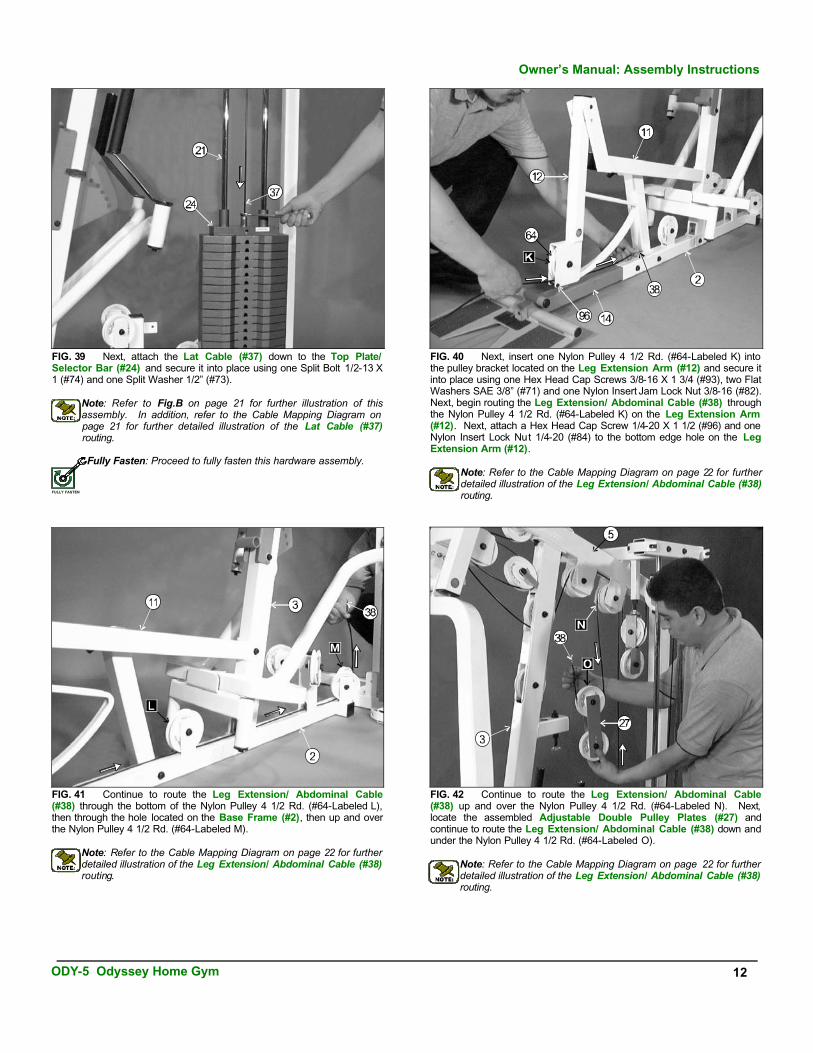
FIG. 42 Continue to route the Leg Extension/ Abdominal Cable(#38) up and over the Nylon Pulley 4 1/2 Rd. (#64-Labeled N). Next,locate the assembled Adjustable Double Pulley Plates (#27) andcontinue to route the Leg Extension/ Abdominal Cable (#38) down and under the Nylon Pulley 4 1/2 Rd. (#64-Labeled O).
Note: Refer to the Cable Mapping Diagram on page 22 for further detailed illustration of the Leg Extension/ Abdominal Cable (#38)routing.
FIG. 39 Next, attach the Lat Cable (#37) down to the Top Plate/Selector Bar (#24) and secure it into place using one Split Bolt 1/2-13 X 1 (#74) and one Split Washer 1/2” (#73).
Note: Refer to Fig.B on page 21 for further illustration of thisassembly. In addition, refer to the Cable Mapping Diagram on page 21 for further detailed illustration of the Lat Cable (#37)routing.
Fully Fasten: Proceed to fully fasten this hardware assembly.
FIG. 40 Next, insert one Nylon Pulley 4 1/2 Rd. (#64-Labeled K) into the pulley bracket located on the Leg Extension Arm (#12) and secure it into place using one Hex Head Cap Screws 3/8-16 X 1 3/4 (#93), two Flat Washers SAE 3/8” (#71) and one Nylon Insert Jam Lock Nut 3/8-16 (#82). Next, begin routing the Leg Extension/ Abdominal Cable (#38) throughthe Nylon Pulley 4 1/2 Rd. (#64-Labeled K) on the Leg Extension Arm (#12). Next, attach a Hex Head Cap Screw 1/4-20 X 1 1/2 (#96) and one Nylon Insert Lock Nut 1/4-20 (#84) to the bottom edge hole on the LegExtension Arm (#12).
Note: Refer to the Cable Mapping Diagram on page 22 for furtherdetailed illustration of the Leg Extension/ Abdominal Cable (#38) routing.
FIG. 41 Continue to route the Leg Extension/ Abdominal Cable(#38) through the bottom of the Nylon Pulley 4 1/2 Rd. (#64-Labeled L), then through the hole located on the Base Frame (#2), then up and over the Nylon Pulley 4 1/2 Rd. (#64-Labeled M).
Note: Refer to the Cable Mapping Diagram on page 22 for further detailed illustration of the Leg Extension/ Abdominal Cable (#38)routing.
FULLY FASTEN
ODY-5 Odyssey Home Gym 12
Owner’s Manual: Assembly Instructions

FIG. 46 Next, attach the Pec Dec Cable (#39) to the Left Pec Dec Arm (#7) and secure it into place using one Strap Bracket #20 (#102),one Hex Head Cap Screw 3/8-16 X 1 3/4 (#93), one Nylon Spacer 3/8 X 3/8 (#104), two Flat Washers SAE 3/8” (#71) and one Nylon Insert Lock Nut 3/8-16 (#81). Refer to Fig. A on page 23 for further clarification of this hardware assembly.
Note: Make sure to attach the Strap Bracket #20 (#102) with its slotted groove facing toward the Pec Dec Arm's cam to allow the Pec Dec Cable (#39) to be flush with the Pec Dec Arm's cam.
FIG. 43 Continue to route the Leg Extension/ Abdominal Cable(#38) up and over the Nylon Pulley 4 1/2 Rd. (#64-Labeled P). Next,locate the Closed-End Double Pulley Bracket (#26) and continue to route the Leg Extension/ Abdominal Cable (#38) down and under the Nylon Pulley 4 1/2 Rd. (#64-Labeled Q), as shown above.
Note: Refer to the Cable Mapping Diagram on page 22 for further detailed illustration of the Leg Extension/ Abdominal Cable (#38)routing.
FIG. 45 Next, attach the Abdominal Strap (#44), one Nylon Ball 1 3/4 X 5/16 (#103) and a Strap Bracket #20 (#102) to the Leg Extension/Abdominal Cable (#38) and secure them it into place using one Shoulder Bolt 3/8 X 3/4 (#101) and one Nylon Insert Lock Nut 5/16-18 (#83). Usethe supplied Hex Key Long 1/8” (#109) to secure the Shoulder Bolt 3/8 X 3/4 (#101) into place. Refer to Fig. A on page 22 for further clarification of this hardware assembly.
FIG. 44 Continue to route the Leg Extension/ Abdominal Cable(#38) through the hole located on the Front Upright (#3), then up andover the Nylon Pulley 4 1/2 Rd. (#64-Labeled R).
Note: Refer to the Cable Mapping Diagram on page 22 for further detailed illustration of the Leg Extension/ Abdominal Cable (#38) routing.
13 ODY-5 Odyssey Home Gym
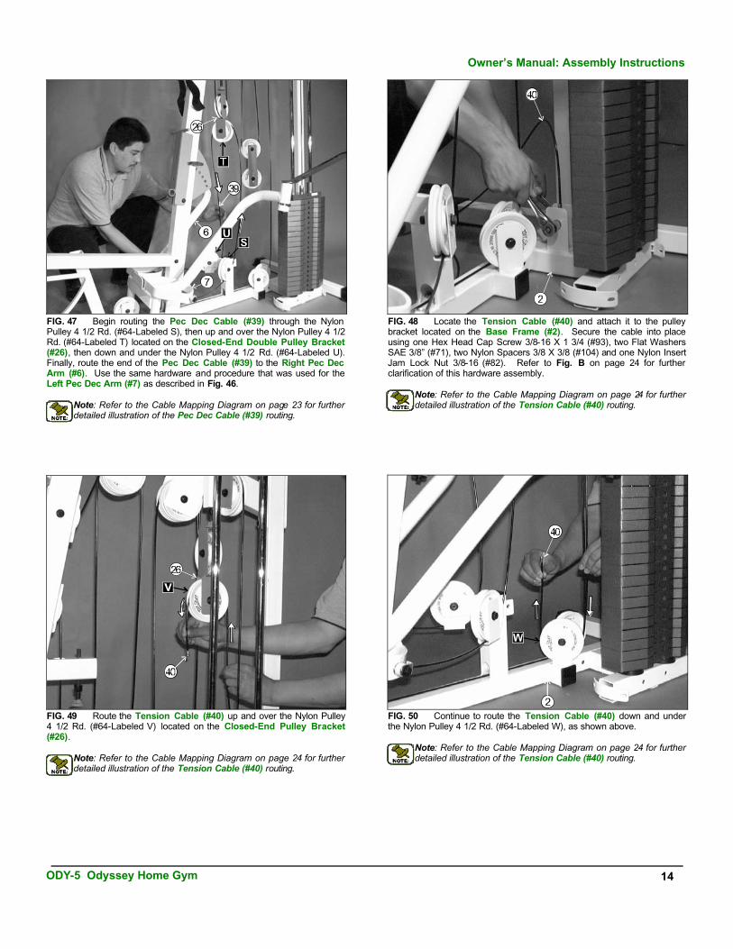
FIG. 47 Begin routing the Pec Dec Cable (#39) through the Nylon Pulley 4 1/2 Rd. (#64-Labeled S), then up and over the Nylon Pulley 4 1/2 Rd. (#64-Labeled T) located on the Closed-End Double Pulley Bracket (#26), then down and under the Nylon Pulley 4 1/2 Rd. (#64-Labeled U). Finally, route the end of the Pec Dec Cable (#39) to the Right Pec Dec Arm (#6). Use the same hardware and procedure that was used for theLeft Pec Dec Arm (#7) as described in Fig. 46.
Note: Refer to the Cable Mapping Diagram on page 23 for further detailed illustration of the Pec Dec Cable (#39) routing.
FIG. 48 Locate the Tension Cable (#40) and attach it to the pulley bracket located on the Base Frame (#2). Secure the cable into place using one Hex Head Cap Screw 3/8-16 X 1 3/4 (#93), two Flat Washers SAE 3/8” (#71), two Nylon Spacers 3/8 X 3/8 (#104) and one Nylon Insert Jam Lock Nut 3/8-16 (#82). Refer to Fig. B on page 24 for further clarification of this hardware assembly.
Note: Refer to the Cable Mapping Diagram on page 24 for further detailed illustration of the Tension Cable (#40) routing.
FIG. 49 Route the Tension Cable (#40) up and over the Nylon Pulley 4 1/2 Rd. (#64-Labeled V) located on the Closed-End Pulley Bracket(#26).
Note: Refer to the Cable Mapping Diagram on page 24 for further detailed illustration of the Tension Cable (#40) routing.
FIG. 50 Continue to route the Tension Cable (#40) down and under the Nylon Pulley 4 1/2 Rd. (#64-Labeled W), as shown above.
Note: Refer to the Cable Mapping Diagram on page 24 for further detailed illustration of the Tension Cable (#40) routing.
ODY-5 Odyssey Home Gym 14
Owner’s Manual: Assembly Instructions
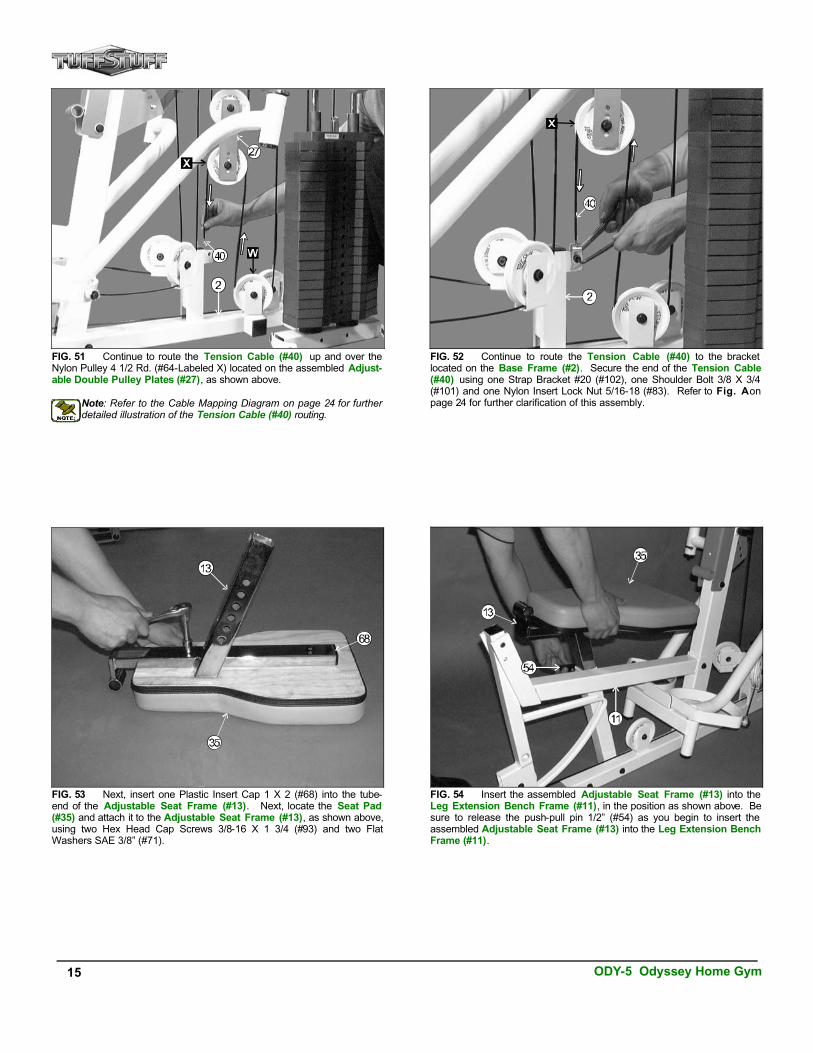
FIG. 51 Continue to route the Tension Cable (#40) up and over the Nylon Pulley 4 1/2 Rd. (#64-Labeled X) located on the assembled Adjust-able Double Pulley Plates (#27), as shown above.
Note: Refer to the Cable Mapping Diagram on page 24 for further detailed illustration of the Tension Cable (#40) routing.
FIG. 52 Continue to route the Tension Cable (#40) to the bracket located on the Base Frame (#2). Secure the end of the Tension Cable(#40) using one Strap Bracket #20 (#102), one Shoulder Bolt 3/8 X 3/4 (#101) and one Nylon Insert Lock Nut 5/16-18 (#83). Refer to Fig. A on page 24 for further clarification of this assembly.
FIG. 53 Next, insert one Plastic Insert Cap 1 X 2 (#68) into the tube-end of the Adjustable Seat Frame (#13). Next, locate the Seat Pad (#35) and attach it to the Adjustable Seat Frame (#13), as shown above, using two Hex Head Cap Screws 3/8-16 X 1 3/4 (#93) and two FlatWashers SAE 3/8” (#71).
FIG. 54 Insert the assembled Adjustable Seat Frame (#13) into the Leg Extension Bench Frame (#11), in the position as shown above. Besure to release the push-pull pin 1/2” (#54) as you begin to insert the assembled Adjustable Seat Frame (#13) into the Leg Extension Bench Frame (#11).
15 ODY-5 Odyssey Home Gym

FIG. 57 Next, attach one Foam Foot Roll 7 X 4 X 1 (#62) to each end of the three tubes as shown above. Refer to the Exploded View Diagram on page 26 for further clarification of this assembly.
FIG. 58 Next, insert one Foot Roll Plastic End Cap 1” (#69) to each end of the three tubes as shown above. Refer to the Exploded ViewDiagram on page 26 for further clarification of this assembly.
FIG. 55 Next, insert one Foot Roll Tube 1 X 16 (#31) into thereceptacle located on the end of the Adjustable Seat Frame (#13).Then, insert one Foot Roll Tube 1 X 16 (#31) into the receptacle locatedon the Leg Extension Arm (#12). Next, insert one Foot Roll Tube 1 X 27 (#30) into the receptacle of the Adjustable Back Pad Bracket (#10),as shown above. Be sure all the tubes are centered at the receptacles from end-to-end.
FIG. 56 Secure, both, the Foot Roll Tube 1 X 16 (#31) on the AdjustableSeat Frame (#13) and the Foot Roll Tube 1 X 27 (#30) on the AdjustableBack Pad Bracket (#10) into place using two Set Screws 1/4-20 X 1/4 (#49), as shown above. Use the supplied Hex Key Long 1/8” (#109) to properly secure the Set Screws 1/4-20 X 1/4 (#49) into place. Refer to Fig. 69 on page 27 for further illustration on securing the Foot Roll Tube 1 X 27 (#30).
ODY-5 Odyssey Home Gym 16
Owner’s Manual: Assembly Instructions
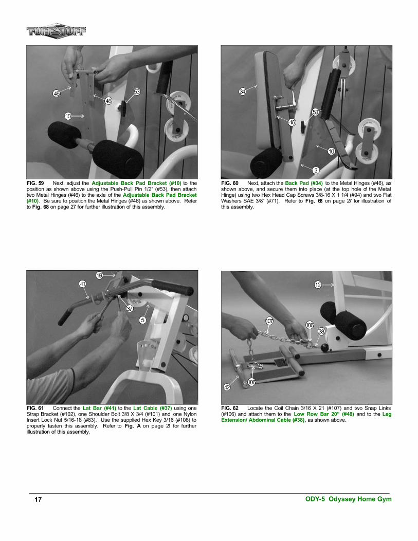
FIG. 59 Next, adjust the Adjustable Back Pad Bracket (#10) to theposition as shown above using the Push-Pull Pin 1/2” (#53), then attach two Metal Hinges (#46) to the axle of the Adjustable Back Pad Bracket (#10). Be sure to position the Metal Hinges (#46) as shown above. Referto Fig. 68 on page 27 for further illustration of this assembly.
FIG. 60 Next, attach the Back Pad (#34) to the Metal Hinges (#46), as shown above, and secure them into place (at the top hole of the Metal Hinge) using two Hex Head Cap Screws 3/8-16 X 1 1/4 (#94) and two Flat Washers SAE 3/8” (#71). Refer to Fig. 68 on page 27 for illustration ofthis assembly.
FIG. 61 Connect the Lat Bar (#41) to the Lat Cable (#37) using one Strap Bracket (#102), one Shoulder Bolt 3/8 X 3/4 (#101) and one Nylon Insert Lock Nut 5/16-18 (#83). Use the supplied Hex Key 3/16 (#108) toproperly fasten this assembly. Refer to Fig. A on page 21 for further illustration of this assembly.
FIG. 62 Locate the Coil Chain 3/16 X 21 (#107) and two Snap Links (#106) and attach them to the Low Row Bar 20” (#48) and to the LegExtension/ Abdominal Cable (#38), as shown above.
17 ODY-5 Odyssey Home Gym

FIG. 63 In replacement of the Low Row Bar 20” (#42), locate the Coil Chain 3/16 X 21 (#107) and two Snap Links (#106) and attach them to the Leather Ankle Strap (#43), as shown above.
FIG. 64 To attach the Standard Decal Weight Numbers (#100) to the Weight Stack. we recommend using a piece of masking tape as a guide to vertically center the Standard Decal Weight Numbers (#100), as shown above. Begin with 10 at the Top Plate/ Selector Bar (#24), 15 next, and so on.
Updated: The Decal Weight Numbers have been replaced by the Decal Weight Numbers illustrated on Fig. 73. Refer to Fig. 73 on page 28 to complete this assembly.
ODY-5 Odyssey Home Gym 18
Owner’s Manual: Assembly Instructions
Update: The Decal Weight Numbers pictured in this manual differ in shape and appearance to the supplied with this unit.
UPDATED
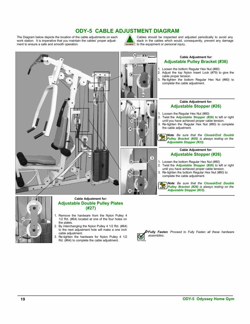
ODY-5 CABLE ADJUSTMENT DIAGRAM
Fully Fasten: Proceed to Fully Fasten all these hardwareassemblies.
FULLY FASTEN
Cable Adjustment for:
Adjustable Pulley Bracket (#36)
1. Loosen the bottom Regular Hex Nut (#80)2. Adjust the top Nylon Insert Lock (#79) to give the
cable proper tension.3. Re-tighten the bottom Regular Hex Nut (#80) to
complete the cable adjustment.
Cable Adjustment for:
Adjustable Stopper (#26)
1. Loosen the Regular Hex Nut (#80)2. Twist the Adjustable Stopper (#26) to left or right
until you have achieved proper cable tension.3. Re-tighten the Regular Hex Nut (#80) to complete
the cable adjustment.
Note: Be sure that the Closed-End DoublePulley Bracket (#26) is always resting on the Adjustable Stopper (#33).
Cable Adjustment for:
Adjustable Stopper (#26)
1. Loosen the bottom Regular Hex Nut (#80)2. Twist the Adjustable Stopper (#26) to left or right
until you have achieved proper cable tension.3. Re-tighten the bottom Regular Hex Nut (#80) to
complete the cable adjustment.
Note: Be sure that the Closed-End DoublePulley Bracket (#26) is always resting on the Adjustable Stopper (#33).
Cable Adjustment for:
Adjustable Double Pulley Plates (#27)
1. Remove the hardware from the Nylon Pulley 41/2 Rd. (#64) located at one of the four holes on the plates.
2. By interchanging the Nylon Pulley 4 1/2 Rd. (#64) to the next adjustment hole will make a one inch cable adjustment.
3. Re-tighten the hardware for Nylon Pulley 4 1/2Rd. (#64) to complete the cable adjustment.
The Diagram below depicts the location of the cable adjustments on each work station. It is imperative that you maintain the cables’ proper adjust-ment to ensure a safe and smooth operation.
Cables should be inspected and adjusted periodically to avoid any slack in the cables which would, consequently, prevent any damageto the equipment or personal injury.
19 ODY-5 Odyssey Home Gym
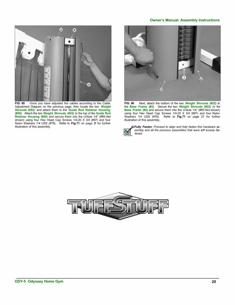
FIG. 65 Once you have adjusted the cables according to the Cable Adjustment Diagram on the previous page, then locate the two WeightShrouds (#22) and attach them to the Guide Rod Retainer Housing (#20). Attach the two Weight Shrouds (#22) to the top of the Guide Rod Retainer Housing (#20) and secure them into the U-Nuts 1/4” (#85-Notshown) using four Hex Head Cap Screws 1/4-20 X 3/4 (#97) and four Nylon Washers 1/4 USS (#78). Refer to Fig.71 on page 27 for further illustration of this assembly.
FIG. 66 Next, attach the bottom of the two Weight Shrouds (#22) to the Base Frame (#2). Secure the two Weight Shrouds (#22) to theBase Frame (#2) and secure them into the U-Nuts 1/4” (#85-Not shown)using four Hex Head Cap Screws 1/4-20 X 3/4 (#97) and four Nylon Washers 1/4 USS (#78). Refer to Fig.71 on page 27 for furtherillustration of this assembly.
Fully Fasten: Proceed to align and fully fasten this hardware as-sembly and all the previous assemblies that were left loosely fas-tened.
FULLY FASTEN
Owner’s Manual: Assembly Instructions
ODY-5 Odyssey Home Gym 20

CA
BL
E M
AP
PIN
G D
IAG
RA
M F
OR
:
Lat
Cab
le (
#37)
FIG
. A
FIG
. B
21 ODY-5 Odyssey Home Gym
SPL
ITB
OL
T TH
RE
AD
ED
SOC
KE
T
CA
BL
EE
ND
SPL
ITW
ASH
ER

CA
BL
E M
AP
PIN
G D
IAG
RA
M F
OR
:
Leg
Exten
sion
/ Ab
do
min
al Cab
le (#38)
FIG
. B
FIG
. A
ODY-5 Odyssey Home Gym 22

CA
BL
E M
AP
PIN
G D
IAG
RA
M F
OR
:P
ec D
ec C
able
(#3
9)
FIG
. A
23 ODY-5 Odyssey Home Gym

CA
BL
E M
AP
PIN
G D
IAG
RA
M F
OR
:
Ten
sion
Cab
le (#40)
FIG
. B
FIG
. A
ODY-5 Odyssey Home Gym 24

25 ODY-5 Odyssey Home Gym
ODYSSEY-5 PARTS LIST
Item No. Description Part No. Qty Item No. Description Part No. Qty
1 PRESS BAR UP321 1 58 RUBBER GRIP 1 1/4 X 5 1/4 BNH0807 42 BASE FRAME ODY5-02-00 1 59 RUBBER GRIP 1 X 9 BNH0808 23 FRONT UPRIGHT ODY5-03-00 1 60 RUBBER DONUT 3/4 X 2 1/2 BNH0062 24 REAR UPRIGHT ODY5-04-00 1 61 ANTI-SKID TAPE 4 X 7 3/4 BNH0492 45 TOP PULLEY ASSEMBLY ODY5-05-00 1 62 FOAM FOOT ROLL 7 X 4 X 1 BNH0043 66 RIGHT PEC DEC ARM UP322 1 63 SELECTOR PIN W/COIL UP466 17 LEFT PEC DEC ARM UP323 1 64 NYLON PULLEY 4 1/2 RD BNH0556 248 PEC DEC SWIVEL HANDLE UP324 2 65 PLASTIC END CAP 2" SQ W/GROOVE BNH0050 39 LEG EXTENSION AXLE 1/2 X 2 1/2 UP373 1 66 PLASTIC INSERT CAP 2" SQ BNH0012 12
10 ADJUSTABLE BACK PAD BRACKET UP554 1 67 PLASTIC INSERT CAP 1 1/2 SQ BNH0009 111 LEG EXTENSION BENCH FRAME UP555 1 68 PLASTIC INSERT CAP 1 X 2 BNH0005 112 LEG EXTENSION ARM UP325 1 69 FOOT ROLL PLASTIC END CAP 1" BNH0397 613 ADJUSTABLE SEAT FRAME UP171 1 70 FLAT WASHER SAE 1/2" BNH0238 514 LOW ROW STABILIZER ODY5-14-00 1 71 FLAT WASHER SAE 3/8" BNH0239 8615 LOW ROW FOOT SUPPORT ODY5-15-00 1 72 FENDER WASHER 3/8 X 1 1/2 BNH0195 216 DECAL- EXERCISE CHART BNH0888 1 73 SPLIT WASHER 1/2" ZINC BNH0572 117 PRESS BAR SELECTOR HOUSING UP326 1 74 SPLIT BOLT 1/2-13 X 1 BNH0479 118 PIVOT AXLE 1 X 8 1/8 UP152 2 75 RETAINING SNAP RING BNH0419 219 LAT BAR HOLDER 2 X 3 UP327 1 76 SPLIT WASHER 3/8" BNH0658 220 GUIDE ROD RETAINER HOUSING UP328 1 77 NYLON WASHER 3/8 USS BNH0248 421 GUIDE ROD 3/4 X 72 UP124 2 78 NYLON WASHER 1/4 USS BNH0889 822 WEIGHT SHROUD UP332 2 79 NYLON INSERT LOCK NUT 1/2-13 BNH0212 123 10 LB WEIGHT PLATE BNH0904 9 80 REGULAR HEX NUT 1/2-13 BNH0201 424 TOP PLATE/ SELECTOR BAR BNH0876 1 81 NYLON INSERT LOCK NUT 3/8-16 BNH0214 1025 "L" LOCKING PIN BNH0045 1 82 NYLON INSERT JAM LOCK NUT 3/8-16 BNH0365 2826 CLOSED-END DOUBLE PULLEY BRKT UP329 2 83 NYLON INSERT LOCK NUT 5/16-18 BNH0215 327 ADJUSTABLE DOUBLE PULLEY PLATE UP092 2 84 NYLON INSERT LOCK NUT 1/4-20 BNH0213 128 CABLE RETAINER BRACKET L-SHAPED UP014 1 85 U NUT 1/4" BNH0708 829 STABILIZER 14" ODY5-29-00 1 86 HEX HEAD CAP SCREW 3/8-16 X 5 BNH0286 130 FOOT ROLL TUBE 1 X 27 ODY5-30-00 1 87 HEX HEAD CAP SCREW 3/8-16 X 4 1/2 BNH0284 131 FOOT ROLL TUBE 1 X 16 UP053 3 88 HEX HEAD CAP SCREW 3/8-16 X 4 1/4 BNH0317 232 SUPPORT PLATE 1/4 X 2 X 5 UP139 1 89 HEX HEAD CAP SCREW 3/8-16 X 3 1/4 BNH0312 533 ADJUSTABLE STOPPER UP331 2 90 HEX HEAD CAP SCREW 3/8-16 X 3 BNH0282 134 BACK PAD UP128 1 91 HEX HEAD CAP SCREW 3/8-16 X 2 3/4 BNH0278 835 SEAT PAD UP173 1 92 HEX HEAD CAP SCREW 3/8-16 X 2 1/2 BNH0276 536 ADJUSTABLE PULLEY BRACKET UP368 1 93 HEX HEAD CAP SCREW 3/8-16 X 1 3/4 BNH0274 1837 LAT CABLE UP341 1 94 HEX HEAD CAP SCREW 3/8-16 X 1 1/4 BNH0273 338 LEG EXTENSION / ABDOMINAL CABLE ODY5-38-00 1 95 HEX HEAD CAP SCREW 3/8-16 X 1 BNH0275 239 PEC DEC CABLE UP342 1 96 HEX HEAD CAP SCREW 1/4-20 X 1 1/2 BNH0272 140 TENSION CABLE ODY5-40-00 1 97 HEX HEAD CAP SCREW 1/4-20 X 3/4 BNH0890 841 LAT BAR 48" BNH0295 1 98 PLASTIC INSERT CAP 1" RD. BNH0002 442 LOW ROW BAR 20" BNH0294 1 99 HEX HEAD CAP SCREW 3/8-16 X 2 BNH0279 243 LEATHER ANKLE STRAP 20000-ALAS 1 100 STANDARD DECAL WEIGHT NUMBERS BNH0928 144 ABDOMINAL STRAP BNH0821 1 101 SHOULDER BOLT 3/8 X 3/4 BNH0718 345 EDGE PROTECTOR 72 1/4" BNH0587 4 102 STRAP BRACKET #20 BNH0562 546 METAL HINGE BNH0046 2 103 NYLON BALL 1 3/4 X 5/16 BNH0392 347 SET SCREW 3/8-16 X 1/2 BNH0474 7 104 NYLON SPACER 3/8 X 3/8 BNH0392 448 SET SCREW 1/4-20 X 3/8 BNH0772 2 105 HARD GRIP .875 X 8 BNH0523 449 SET SCREW 1/4-20 X 1/4 BNH0790 2 106 SNAP LINK BNH0065 350 NYLON BUSHING 1 X 1 1/2 BNH0531 4 107 COIL CHAIN 3/16 X 21 BNH0017 151 BRONZE BUSHING 1 X 1 1/4 BNH0527 8 108 HEX KEY 3/16 BNH0371 152 BRONZE BUSHING 1/2 X 5/8 BNH0528 2 109 HEX KEY LONG 1/8" BNH0767 153 PUSH-PULL PIN 1/2" (SPECIAL) BNH0520 2 110 PLASTIC INSERT CAP 1 1/4" RD BNH0573 454 PUSH-PULL PIN 1/2" BNH0542 1 111 1" RD SILVER MYLAR DECAL BNH0015 455 RUBBER STOPPER 1 X 1 3/4 X 3 BNH0791 2 112 RUBBER BUMPER 3/8 X 1 1/2 BNH0514 156 RUBBER STOPPER 1/8 X 2 X 4 BNH0688 1 113 15 LB WEIGHT PLATE BNH0926 557 RUBBER STOPPER 1/8 X 1 1/2 X 5 BNH0688 1 114 5 LB WEIGHT PLATE BNH0927 5
COLOR CHARTGRAY= SUB-ASSEMBLY PARTSBLACK= HARDWARE

Tu
ff Stu
f f
Tuff S
tuff
Tu
ff Stu
f f
OD
Y-5 E
XP
LO
DE
D V
IEW
DIA
GR
AM
ODY-5 Odyssey Home Gym 26
FIG
. AT
HE
2 PUL
LE
YS
INC
LU
DE
SAM
E
BO
LT
S, WA
SHE
RS,
AN
D N
UT
S.
FIG
. BT
HE
2 PUL
LE
YS
INC
LU
DE
SAM
E
BO
LT
S, WA
SHE
RS,
AN
D N
UT
S.
NY
LO
N W
AS
HE
RS
GO
INSID
E.
SE
E F
IG. B
SE
EF
IG. B

FIG. 67 FIG. 68
FIG. 69 FIG. 70 FIG. 71
27 ODY-5 Odyssey Home Gym
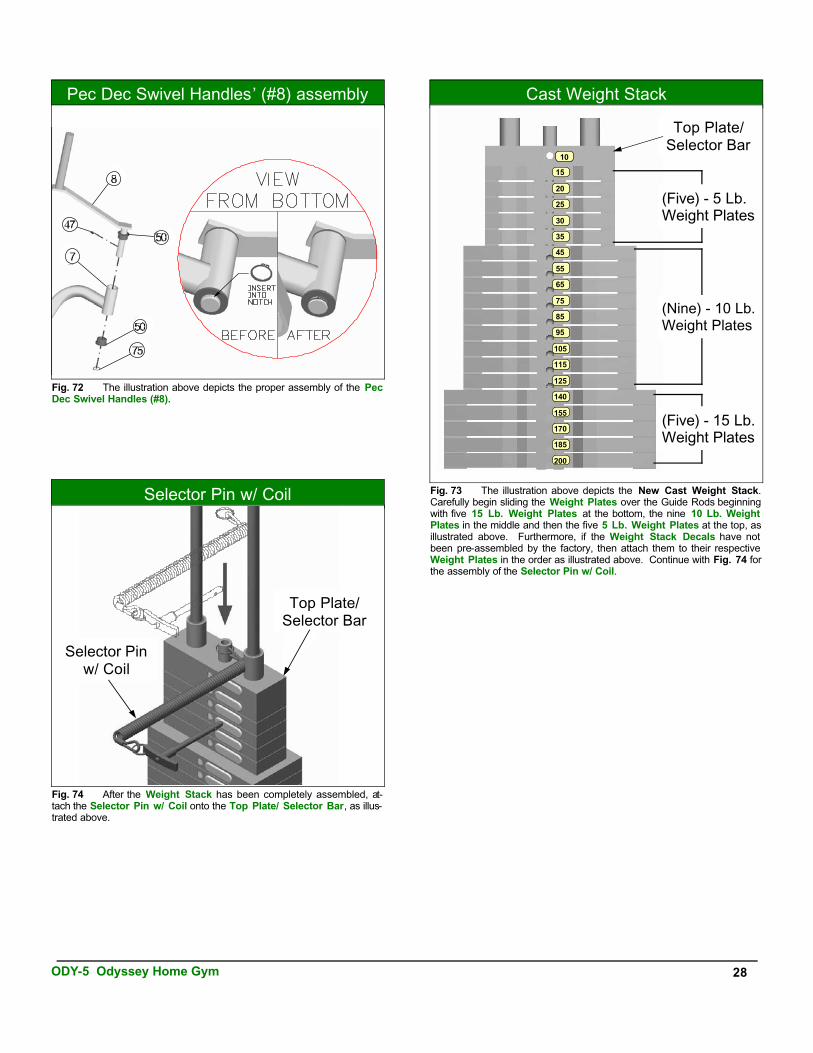
Cast Weight Stack
(Five) - 5 Lb.Weight Plates
(Nine) - 10 Lb.Weight Plates
(Five) - 15 Lb.Weight Plates
Top Plate/ Selector Bar
Fig. 73 The illustration above depicts the New Cast Weight Stack.Carefully begin sliding the Weight Plates over the Guide Rods beginning with five 15 Lb. Weight Plates at the bottom, the nine 10 Lb. Weight Plates in the middle and then the five 5 Lb. Weight Plates at the top, as illustrated above. Furthermore, if the Weight Stack Decals have not been pre-assembled by the factory, then attach them to their respective Weight Plates in the order as illustrated above. Continue with Fig. 74 for the assembly of the Selector Pin w/ Coil.
Selector Pin w/ Coil
Fig. 74 After the Weight Stack has been completely assembled, at-tach the Selector Pin w/ Coil onto the Top Plate/ Selector Bar, as illus-trated above.
Top Plate/ Selector Bar
Selector Pin w/ Coil
Pec Dec Swivel Handles’ (#8) assembly
AP-250S Cast Weight Stack
Fig. 72 The illustration above depicts the proper assembly of the PecDec Swivel Handles (#8).
ODY-5 Odyssey Home Gym 28
10
15
20
25
30
35
45
55
65
75
85
95
105
115
125
140
155
170
185
200
Adjustment Features
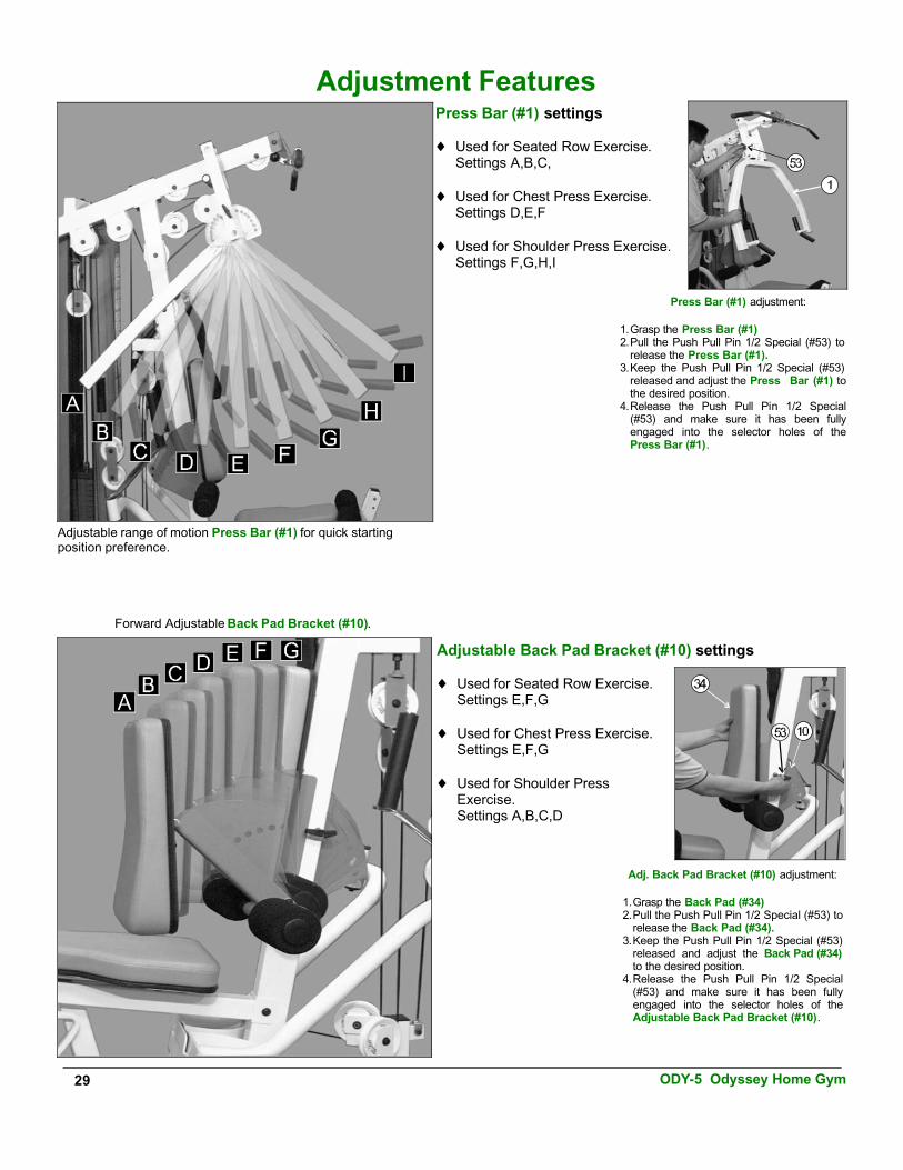
Adjustable range of motion Press Bar (#1) for quick starting position preference.
Press Bar (#1) settings
♦ Used for Seated Row Exercise.Settings A,B,C,
♦ Used for Chest Press Exercise.Settings D,E,F
♦ Used for Shoulder Press Exercise.Settings F,G,H,I
Adjustable Back Pad Bracket (#10) settings
♦ Used for Seated Row Exercise.Settings E,F,G
♦ Used for Chest Press Exercise.Settings E,F,G
♦ Used for Shoulder Press Exercise.Settings A,B,C,D
Adj. Back Pad Bracket (#10) adjustment:
1.Grasp the Back Pad (#34)2.Pull the Push Pull Pin 1/2 Special (#53) to
release the Back Pad (#34).3.Keep the Push Pull Pin 1/2 Special (#53)
released and adjust the Back Pad (#34)to the desired position.
4.Release the Push Pull Pin 1/2 Special(#53) and make sure it has been fullyengaged into the selector holes of theAdjustable Back Pad Bracket (#10).
Forward Adjustable Back Pad Bracket (#10).
Press Bar (#1) adjustment:
1.Grasp the Press Bar (#1)2.Pull the Push Pull Pin 1/2 Special (#53) to
release the Press Bar (#1).3.Keep the Push Pull Pin 1/2 Special (#53)
released and adjust the Press Bar (#1) to the desired position.
4.Release the Push Pull Pin 1/2 Special(#53) and make sure it has been fullyengaged into the selector holes of thePress Bar (#1).
29 ODY-5 Odyssey Home Gym

Weight Selection
1. Grasp the Weight Selector Pin (#63).2. Insert the Weight Selector Pin (#63) into desired Weight Plate. The
Decal Weight Number (#100) on the selected Weight Plate (#23) willshow the amount of weight selected. The Top / Plate Selector Bar (#24) must be resting on the top of the Weight Stack.
3. Make sure the Weight Selector Pin (#63) has been fully inserted into the Weight Plate receptacle.
Seat Pad (#35) adjustment:
1. Grasp the Seat Pad (#35)2. Pull the Push Pull Pin 1/2 (#54) to release the Adjustable Seat
Frame (#13).3. Keep the Push Pull Pin 1/2 (#54) released and adjust the Seat Pad
(#35) to the desired position.4. Release the Push Pull Pin 1/2 (#54) and make sure it has been fully
engaged into the selector holes of the Leg Extension Bench Frame(#11).
Adjustment Features
Locking the Leg Extension Arm (#12)
1. Locate the L-Locking Pin (#25).2. Insert the L-Locking Pin (#25) through the Leg Extension Bench
Frame (#11) and the Leg Extension Arm (#12), as shown above.
Leg Extension Arm Unlock Used on Exercises:♦ Leg Extension
♦ Leg Curl Leg Extension Arm Lock Used on Exercises:♦ Low Row
♦ Standing Arm Curl
♦ Inner / Outer Thigh
Positioning the Low Row Foot Support (#15)
1. Picture above at the left shows the Low Row Foot Support (#15)positioned and ready for standing. It is IMPORTANT that when in this position, you must stand completely on the Low Row Foot Support (#15) and not off. This is done to prevent the unit from tipping during this workout exercise.
2. Picture above at the right shows the Low Row Foot Support (#15) positioned and ready for the seated rowing exercise.
Note: Do not drop the Low Row Foot Support (#15) or leave it in the position as pictured above at the right. Always lower LowRow Foot Support (#15) when not is use.
Update: The Weight Stacks pictured in this manual differ in shape and appearance to the supplied with this unit.
ODY-5 Odyssey Home Gym 30

Adjustment FeaturesThe picture to the left shows the Pec Dec Arms (#6,#7) and the PecDec Swivel Handles (#8) adjusted to the inside of the unit to allow thePress Bar (#1) to move freely during the Deated Rowing Exercise.
Safety: The Left Pec Dec Arm (#7) and the Right Pec DecArm (#6) must be adjusted to the position pictured at the left to avoid the chance of injuring during the Seated Rowing Exer-cise.
The picture to the right shows the Press Bar (#1) adjusted to rear of the unit to allow the Left Pec Dec Arms (#6,#7) and the Pec Dec Swivel Handles (#8) to move freely during the Pec DecExercise.
Safety: The Press Bar (#1) must be adjusted to theposition pictured at the right to avoid the chance ofinjuring during the Pec Dec Exercise.
31 ODY-5 Odyssey Home Gym

8. Check that the Push Pull Pins 1/2 Special (#53) and thePush Pull Pin 1/2 (#54) nuts are fully fastened (See Fig.75). In addition, be sure the springs in the Push Pull Pins 1/2 (#53, #54) are operating freely.
9. Check welds to be free of cracks.
10. Failure to perform routine maintenance could result inpersonal injury and/or equipment damage.
M aintenance Information
1. Lubrication of all moving parts is essential to the longevity and optimal performance of your Odyssey Home Gym.Initial lubrication of some parts of your gym have beendone at the factory, but the weight stack guide rods must be lubricated at the time of assembly. We recommend a clear aerosol, silicone or teflon spray.
Note: Do not use oil based lubricants as they will attract dust,dirt and grime, and will eventually gum up and erode bushings and sealed bearings.
2. All pulleys and bushings should be checked regularly forsigns of wear.
3. Check and adjust cable tension periodically as it willmaintain proper anatomical function.
4. Periodically check all moving parts, upholstery and grips for signs of wear or damage. If there is a problem orreplacement part is necessary, STOP USING THEEQUIPMENT and immediately contact your local Tuff Stuff retailer or call our Customer Service Department. Replaceparts using only genuine Tuff Stuff parts.
5. As needed, upholstery may be cleaned with a mildsolution of soap and water. Regular use of a vinyltreatment will add to the life and appearance of yourupholstery.
6. All chrome plated surfaces should be cleaned regularly to prolong the life and luster of the finish. Wipe machinedown with a damp cloth and dry thoroughly each day. Atleast once a week your chrome equipment should bepolished with a commercial grade or automotive typechrome polish.
7. When checking the bolts and nuts, be sure they are allfully fastened. If there is a bolt or nut that continuously loosens obtain a replacement through your local Tuff Stuff retailer or call our Customer Service Department.
Fig. 75 Warning: Be sure the Push Pull Pin nuts are fully fastened. Fasten if necessary.
Push PullPin Hex Nut
Push PullPin Hex Nut
Maintenance
ODY-5 Odyssey Home Gym 32

Optional Stations
ODY-5LP Leg PressL 86” W 94” H 83”
ODY-5TO Inner / Outer ThighL 86” W 101” H 83”
ODY-5AB Ab / BackL 85” W 86” H 83”
33 ODY-5 Odyssey Home Gym
85”
86”
85”
101”
86”
94”

ODY-5 Odyssey Home Gym 34
N o t e s

DO NOT DISC ARD THIS MANUAL
TASK INDUSTRIES, INC.1325 E. Franklin Ave., Pomona, CA 91766
Ph: 909-629-1600 Fax: 909-629-4967 E-mail: [email protected] Net: www.tuffstuff.net
H OM E L I F ET IM E W ARRANTY
TuffStuff products are warranted to the retail purchaser to be free from defects in materials and workmanship. TuffStuff exclusive Home Lifetime Warranty coverage extends for the life of the product while owned by the original retail purchaser, and used only in a home or residential setting unless otherwise noted in the owner’s manual.
This warranty does not cover: 1. TuffStuff products sold for and used in a commercial or institutional setting. 2. Any damage, failure or loss caused by accident, misuse, neglect, abuse, improper assembly, improper
maintenance, or failure to follow instructions or warnings in the owner’s manual and warning labels posted on the machine.
3. Use of products in a manner for which they were not designed. 4. Original product that is altered, or the use of replacement parts and components of another manufac-
turer other than TuffStuff.
Limitations: The foregoing shall constitute the sole remedy of the purchaser and the sole liability of TuffStuff with regard to warranty, whether express or implied by operation of law or otherwise, including but not limited to any implied warranties of merchantability or fitness. TuffStuff shall in no event be liable for incidental or consequential losses, damages or expenses in connection with exercise products. TuffStuff’s liability hereunder is expressly limited to the repairs or replacements of warranted defective parts.
Procedures: Warranty service will be performed at TuffStuff’s facility in Pomona, California. TuffStuff will have the option of either repair or replacement at no charge for any defective product. Purchaser is responsible for installation of repaired or replaced parts and all transportation and insurance costs on returned or replaced equipment to and from TuffStuff’s facility in Pomona.
This warranty gives you specific legal rights and you may also have other rights, which may vary from state to state. Effective July 1, 2004.
This warranty is the final, complete and exclusive agreement of the parties with respect to the quality or performance of the equipment and no action for breach of this written warranty or any implied warranty shall be commenced more than one (1) year after the accrual of the cause of action. No modification of this warranty or waiver of its terms shall be binding on either party unless approved in writing by an authorized representative of the party. Contact TuffStuff at 1325 E. Franklin Avenue, Pomona, California 91766, before returning any defective equipment.
Note: Retain your sales receipt and be sure to mail in the warranty registration card to insure that a permanent record of your purchase is on file with the factory and to avoid unnecessary delays in warranty service.