owner’s manual external furnace model: 1660efe · 853017b-3902h owner’s manual external furnace...
TRANSCRIPT

853017B-3902H
Owner’s ManualExternal Furnace Model: 1660EFE
United States Stove Company 227 Industrial Park Road • South
Pittsburg, TN 37380 • www.usstove.com
SAFETY NOTICE:If this furnace is not properly installed, a house fire may result! For your safety, follow these installation instructions.
Contact local building or fire officials about restrictions and installation requirements in your area. This furnace must be installed by a qualified technician. Keep these instructions for future reference.
Report No: 0215WH084S 0215WH084E
Safety Tested to UL 391 (R2014)
U.S. ENVIRONMENTAL PROTECTION AGENCY Certified to comply with the 2017 particulate emission standards. Not approved for sale
after May 15, 2020
CALIFORNIA PROPOSITION 65 WARNING:This product can expose you to chemicals including carbon monoxide, which is known to the State of California to cause cancer, birth defects and/or other
reproductive harm. For more information, go to www.P65warnings.ca.gov
Ce produit peut vous exposer à des produits chimiques, y compris le monoxyde de carbone, qui est connu dans l'État de Californie pour causer le cancer, des malformations congénitales et / ou d'autres problèmes de reproduction. Pour plus d'informations, visitez www.P65warnings.ca.gov

-2-
This manual describes the installation and operation of the United States Stove, 1660EFE wood heater. This heater meets the 2016 U.S. Environmental Protection Agency’s emission limits for wood heaters sold after May 15, 2017. Under specific EPA test conditions this heater has been shown to deliver heat at a rate of 27,766 to 66,768 BTU/hr. This heater achieved a particulate emissions rate of 0.586 lbs/mmBTU when tested to method CSA B415.1-10 (*and an overall efficiency of 50.2%.) The maximum overall heat output of this heater was tested to be 73,849 BTU/hr.
This wood heater has a manufacturer-set minimum low burn rate that must not be altered. It is against federal regulations to alter this setting or otherwise operate this wood heater in a manner inconsistent with operating instructions in this manual.
The operation of this wood heater in a manner inconsistent with the owner’s manual will void your warranty and is also against federal regulations.
This heater is designed to burn natural wood only. Higher efficiencies and lower emissions generally result when burning air dried seasoned hardwoods, as compared to softwoods or to green or freshly cut hardwoods.
This wood heater needs periodic inspection and repair for proper operation. It is against federal regulations to operate this wood heater in a manner inconsistent with operating instructions in this manual.
Combustible: WoodFlue Pipe Diameter: 6” (153cm)Flue Pipe Type: (Standard Single Wall or Double Wall): Black or Blued Steel 2100°F (650°C) Class “A” or UL103HTMinimum Chimney Height: 12’Maximum Log Length: 28”Electrical: 120V, 60Hz 8 AMPSDimensionsCombustion Chamber:Width x Depth: 17.4” X 28.3”
Volume:Cubic Feet: 6.27 cubic feet
Door Opening: Width x Height: 12.641” X 12.641”
SpecificationsCONGRATULATIONS!
You’ve purchased a heater from North America’s oldest manufacturer of wood burning products.By heating with wood you’re helping to CONSERVE ENERGY!
Wood is our only Renewable Energy Resource. Please do your part to preserve our wood supply. Plant at least one tree each year. Future generations will thank you.
0215WH084E
Note: Register your product on line at www.usstove.com. Save your receipt with your records for any claims.

-3-
INTRODUCTIONThank You for your purchase of a U.S. Stove External
Furnace. Your decision to buy our furnace was undoubtedly reached after much careful thought and consideration. We are very proud you chose this furnace and trust you will receive the comfort and economy that others realize when heating with a U.S. Stove product.Your dealer is important in your experience with
the furnace not only with the purchase, but for recommendations for professional installation for your home. The qualified professional installer has been expertly trained in solid-fuel furnace installation to assure the safety and comfort for your family while saving you money. Trust your experienced installer. They are specialist in this field.
IMPORTANTBefore installing and using your furnace, please read
the following pages thoroughly and carefully. If you follow the instructions, your furnace will give you safe and more dependable service for years to come.• Check your local codes. This installation must
comply with their rulings.• This is an outdoor hot air furnace and must NOT be
installed inside the home or a building.• This furnace must be connected to a 110 volt
Ground Fault Circuit Interrupter (GFCI) outlet suitable for outdoor use.
• A back-up generator, 2,000 watts minimum, is recommended in case of a power failure.
• Always have a properly functioning smoke or ionization detector and a CO detector installed in your home.
• To prevent injury or damage, do not allow anyone who is unfamiliar with the furnace to operate it.
• Spend adequate time with your furnace to become well acquainted with the different settings and how each will affect its burning patterns. It is impossible to state just how each setting will affect your furnace because of the variations in each installation.
DISCLAIMER NOTICEThe BTU ranges and heating capacity specifications
are provided as a guide and in no way guarantee the output or capacity of this unit. The actual BTU output depends on the type of fuel being burned and its conditions, the thermostat setting, the draft adjustment and the chimney to which the unit is attached. The actual area that this unit will heat depends on factors such as the conditions of the building, heat loss, type of construction, amount of insulation, type of air movement, the location of the unit and more importantly the duct work and return air facility.Warning: Do not alter this appliance in any way other
than specified in these instructions. Doing so may void your warranty.
GENERAL INFORMATIONYour furnace comes ready for installation. Unpack
your furnace and insure that there is no shipping damage. If damage exist, please contact your dealer immediately. Review the items included with your furnace located inside the firebox.1 - 10” Starter Collar1 - 14” Starter Collar for Cold Air Return8 - #10 x 3/4 Screws w/ Sealing Washer1 - Literature PackageThis furnace must be installed as a Stand-Alone Central
Furnace in the US only. The outdoor furnace may be operated with the supplied wall thermostat or a 24 volt thermostat that you supply yourself. The furnace must be placed outdoors on a level noncombustible base, preferably a 4’ x 8’ concrete pad, as close to the home as clearances to combustibles will allow. If locating the furnace more than 10 feet away from the home, a minimum of 12 feet of Class “A” UL103 HT 2100 All Fuel 6 inch chimney pipe is required - Do not place the furnace more than 40 feet away from the home. Maintain all clearances stated in this manual. Class “A” UL103 HT 2100 All Fuel 6” Chimney Pipe is recommended for optimum performance and can be purchased from your local dealer. A Chimney Base Plate (not included)should be installed over the flue outlet and sealed to maintain weather resistance. A 2” clearance to combustibles must be maintained from the pipe. We suggest using either Simpson Dura-Vent or Metal Fab chimney products for your installation. If you choose to use single wall stainless, the flue temperatures will be reduced which promotes the formation of creosote, possibly creating a fire hazard. If you use single wall stainless pipe, the minimum clearance to combustibles is 20”. Attach the appropriate chimney pipe lengths to the chosen chimney base plate and finish with a rain cap. Secure the chimney with guy wires to each of the four anchors point on the furnace. Your furnace requires it’s own chimney system and can not share a flue with another appliance. Once you have selected a location for the furnace and connected your furnace to a chimney and a 110 volt GFCI outlet, you will need to commence an initial firing. DO NOT connect the furnace to your duct work at this time. Your new furnace has a protective coating of oil and paint on the surface which could produce smoke or odors during the initial firing and will burn off. Build a small fire - DO NOT fill the firebox to it’s full capacity for the initial burn. This initial firing allows the metals and castings to cure. After completing the firing and allowing it to cool, you are ready to finish the installation. Refer to the remainder of this manual for detailed instructions.

-4-
Unit Dimensions
5.09
51.37
BLOWER SPEED SELECTOR SWITCH
B
D-RINGS FOR GUY WIRE ATTACHMENT
17.66
LIMIT SWITCH ACCESS
14.92
28.43
43.35
28.00
6.00
14.35 Cold Air Return
Hot Water Coil Access (Optional)
10.00 Hot Air Outlet
A
67.86
49.00
33.93
28.77
9.38

-5-
WOOD SUPPLYSome important rules for preparing good firewood are: Cut, split and stack the wood in the early spring and let
it stand in the sun and wind all summer. Whether you purchase your wood or cut it yourself, spring is the best time to buy or cut your wood to insure it is good and dry come winter. If you live in a damper climate, it will take longer for the wood to season. By far the most important characteristic of any firewood is its moisture content. Firewood with a moisture content higher than twenty percent will burn, but it will be hard to light and keep burning, will make a lot of smoke and will produce less efficient fires with lower sustained BTU output. Plus much of its energy content will be wasted right up the chimney. Firewood should be between 15 and 25 percent moisture to burn properly and to get that dry it must be split and stacked in the open for at least a full summer. All wood burns, but wood that’s cut green (between 50 and more than 100 percent moisture content) burns with more difficulty, because the water in the wood must be boiled off before the actual wood fiber can burn. Air-dried (“seasoned”) wood is generally between 20-30 percent. Kiln-dried firewood generally contains less than 20 percent moisture. Green wood can produce more creosote--a black sooty liquid which deposits and hardens on the inside of your chimney and can ignite, causing a chimney fire. When you stack your wood, you should stack it in an open location where the summer sun can warm it and breezes can help remove moisture. Be sure to cover the top of the wood pile to keep the rain out. It is important that you do not stack unseasoned wood in an unventilated area for it will not dry properly. You shouldn’t allow your firewood to lay on the ground for more than a couple days before stacking , or it will start to mold and rot quickly. Once your wood is seasoned, store it in a dry location before burning.
CLEARANCESSides of furnace, 12”; Rear of furnace, 15” (allow approximately 20” for the return box); Front of furnace, 36”;
Point of Zero Clearance from the Duct: 3 ft. This unit must be installed on a non combustible masonry or concrete surface.
FLUE PIPE INSTALLATIONClearances to combustible materials will vary with the type of flue
connection used. Be sure to maintain the specified clearances for your type of installation.TYPE OF FLUE REQUIREDCONNECTION CLEARANCE
Class A UL103 HT All-Fuel or Equivalent....2”
Double Wall, Stainless Steel or ....6”Double Wall, Black Pipe w/Stainless Steel Inner wall
24 Gauge or Heavier .................20”Single Wall Stainless Steel or Black PipeThe above clearances to combustibles must be maintained.
CHIMNEY REQUIREMENTSA Class “A” UL103 HT 2100 All Fuel 6” Chimney Pipe and Base
Plate should be used for the installation (not included). Do not connect this unit to a chimney or flue serving another appliance. Place the base plate over the flue outlet of the furnace and drill eight(8) pilot holes into the cabinet top. Do not connect this unit to a chimney or flue serving another appliance. Apply a generous amount of high temperature sealant to the bottom of the base plate, and around the flue outlet. Position the base plate over the flue and secure with the eight (8) screws provided. Then attach the flue pipe sections. A minimum chimney height of 6 feet is required not including the rain cap. In order to determine proper chimney height above the roof, measure from the side of the chimney horizontally. As you move up the chimney, the length increases. Once this measurement reaches 10 feet, this is the base height of the chimney. The chimney must be 2 feet taller than the base height. If the chimney is closer than 10 feet from the peak of the roof, the chimney must be 2 feet taller than the peak of the roof. The 2 feet measurement does not include the rain cap. Once correct chimney height is achieved, check the chimney draft. It should not exceed 0.06 inches of water column. Then secure with three screws at each joint and attach guy wires down to the rings located around the top of the furnace cabinet.
22”
12”
20”15”
COMBUSTIBLE WALL
CO
MBU
STIB
LE W
ALL
FLUE
(TOP VIEW)
MINIMUM CLEARANCES TO A COMBUSTIBLE
WALL
CAUTION:DO NOT store
combustible orflammable materials or
liquids near thefurnace.

-6-
NO DUCT WORK INSTALLATIONCold air return must be installed in all installations, even those without an air duct system. If you do not, the
furnace will not be able to heat the home. A filter should be installed in the cold air return. Furnace filters should be checked and cleaned/replaced regularly. When there is no duct system to connect the furnace to, keep the following in mind:1. You must separate the hot air duct from the cold air return. Ideally, locate each at opposite ends of the
home. This method will work well in homes that are built on concrete slabs and should create a good air flow. If you do not, air will not flow evenly through the home.
2. In homes with a basement, you may run the hot air duct to the basement and pull the cold air return from the main floor. This will create the perfect air flow since hot air rises.
CENTRAL DUCT CONNECTIONWhen connecting to a central duct system,
avoid 90 degree elbows as this will reduce air flow delivery. A duct run in excess of 40 feet is NOT RECOMMENDED. The air flow and heat output will be greatly decreased.Run 10” insulated hot air duct from the
outdoor furnace through a wall or window of the structure. Then attach a flexible hot air duct to the existing duct work. Connect the duct with a 45 degree elbow or at an angle so the hot air from the outdoor furnace is delivered downstream. This will insure proper air flow into the system. Avoid delivering hot air through an air conditioning coil as this will cause an obstruction reducing heat output. The following illustrations may be used as examples for your installation.
IMPORTANCE OF PROPER DRAFTDraft is the force which moves air from the appliance up through the chimney. The amount of draft in your
chimney depends on the length of the chimney, local geography, nearby obstructions and other factors. Too much draft may cause excessive temperatures in the appliance. Inadequate draft may cause backpuffing into the room and ‘plugging’ of the chimney. Inadequate draft will cause the appliance to leak smoke into the room through appliance and chimney connector joints. An uncontrollable burn or excessive temperature indicates excessive draft. Take into account the chimney’s location to insure it is not too close to neighbors or in a valley which may cause unhealthy or nuisance conditions.
CONNECTING HOT AIR DUCT TO FURNACEWe strongly recommend that the hot air duct work be installed by a home heating specialist. If doing the
installation yourself, before you decide which installation will best suit your needs, consult a qualified heating technician and follow his recommendations as to the safest and most efficient method of installation. The warm-air supply-duct system shall be constructed of metal in accordance with NFPA 90B, 2-1.1. The plenums installed to the furnace be constructed of metal in accordance with NFPA 90B, 2-1.3. Outside the house you must use 10 inch galvanized pipe, wrapped with weather proof, UV resistant insulation. The 14 inch return may be galvanized pipe and attached to the home so as to not pressurize the home. NEVER reduce the 10” hot air or the 14” return air as this will result in restricted air flow and cause the furnace to not operate properly. NEVER draw cold outside air into the blower housing. By doing so, the furnace’s heat chamber will not reach the necessary temperature to heat the home. The duct work should be designed so the external static pressure does not exceed 0.2 inches water column while developing air velocities of 600 to 1,000 feet per minute in the main trunk duct and 400 to 600 feet per minute at the registers. The heat outlet should never be less than ten inches (10”) round or 79 square inches. This furnace must be installed with a cold air return system. The system must be a minimum of fourteen inches
(14”) to readily transfer the cold air from the home back to the furnace. If desired, a cold air filter box may be constructed with a minimum opening of 225 square inches. The warm-air supply outlet of the outdoor furnace must not be connected to the cold-air-return inlet of an existing central furnace because the possibility exist of components of the existing furnace overheating and may cause the central furnace to operate other than intended.
Types Of Installation

-7-
FUEL DOOR LATCHWith two 1/4-20 x 3/4 hex bolts each, attach the door latches to
the door latch mounting brackets on the left side of the door frames as illustrated. The slots in the brackets and latches are for door seal adjustment. Make the proper adjustments, then tighten the nuts. The door’s gasket should be snug against the door frame on the furnace.
(1) Feed Door Latch(2) 1/4-20 x 3/4 Hex Bolt(2) 1/4-20 Kep Nut
FRONT
SMOKE CURTAIN
SMOKE CURTAINCLIP
NUT
BOLT
1/4-20 NUTSMOKE CURTAIN CLIP
1/4-20 x 1-1/4CARRIAGE BOLT
SMOKE CURTAIN
SMOKE CURTAINUsing two 1/4-20 x 1-1/4” Carriage bolts, the smoke curtain clips and two nuts, attach the smoke curtain in place
above the Fuel Feed Door as shown below. After installation, the smoke curtain should swing freely back into the furnace.(1) Smoke Curtain(2) Smoke Curtain Clips(2) 1/4-20 x 1-1/4 Carriage Bolt(2) 1/4-20 Kep Nut
Furnace Assembly Instructions

-8-
1. To replace the Honeywell Limit Control (A): Unplug from power supply
The control may be removable thru the access panel on item “B”. However it may be easier to remove item “B” entirely for better access. Remove item “B” by means of the eight(8) screws. If silicone, use a utility knife to score the silicone along the edges of the part. Take off the cover of the control (A), remove the three wires, and continue to remove the control by means of the two screws retaining it. Use the wiring diagram in the rear of this manual to re-connect the new control. Reattach item “B” and re-silicone all the seams with weather resistant silicone.2. To remove the return air box (D): Unplug from power
supply.If siliconed, use a utility knife to score the silicone along the
edges of the part. Remove item “B” as described above. Then remove the four(4) screws down each side and the four(4) across the top of the return air box. Pull the box back away from the unit enough that you can reach in to remove the snap-in plug (C) from the top of the box. The power supply cord will need to be feed back thru the plug in the bottom of the air box for complete removal. When re-attaching, make sure that the three plugs in the top of the Fan Center (G) are properly plugged in. Do not forget to put the snap-in plug (C) back in place. Re-silicone all the seams with weather resistant silicone.3. To remove the Distribution Blower (E): Unplug from
power supply.Remove items”B” and “D” as described above. Unplug
the blower from the top of the Fan Center (G). Remove the four(4) screws retaining the blower.4. To remove the Blower Motor: Unplug from power supply.Perform number 3 above. Before removing the motor from
the housing, measure two things:1. The distance from the edge of the motor to the edge
of the motor bracket. Record (d1) _________________2. The distance of the shaft remaining outside the coupling
on the blower wheel. Record (d2) __________________These two measurements dictate the position of the blower
inside the housing and is critical in determining motor longevity. Repositioning of the blower motor, bracket, and wheel in respect to one another should keep as close to the factory position as possible.Remove the three(3) screws (I) from the blower housing.
Then loosen the bolt (J) on the motor shaft. Next, loosen or remove the bolt (K) in the motor bracket to remove the motor. 5. To remove the Blower Capacitor (F): Unplug from
power supply.This may be accomplished by working thru the 12 inch
diameter return duct hole in the Return Box. Otherwise, you must remove items”B” and “D” as described above. Unplug the blower from the top of the Fan Center (G). Using pliers with rubber coated handles, unplug the two connections on the capacitor. Remove the two screws and cap bracket.
Distribution Blower & ACC.
A
C
B
D
C
F
E
HG
J
I
d1
d2
K
All electrical connections should be done by a qualified electrician.
-9-
GENERAL FURNACE OPERATIONAfter installation of the furnace is complete, it is ready for operation. The Honeywell Limit Control, in conjunction
with a wall thermostat, operates the distribution blower and the actuated draft on the front of the furnace. The limit control is located on the rear of the furnace in the upper right corner and is accessible by removing the two screws in the cover plate. DO NOT operate your furnace with this plate removed! The control can be adjusted to your desired blower On/Off times. The factory settings are 100/150/200. The wall thermostat setting operates the ON time of the actuated draft. If the temperature is below the setting on the wall thermostat, the actuated draft will come open. (Recommended setting at 5 to 10 degrees higher than other heating thermostats.) The first two set points on the limit control operates the distribution blower. When the furnace plenum reaches the second set point on the limit control, the distribution blower will come on. If the temperature falls to the first set point, the distribution blower will shut-off. The distribution blower is a three speed blower and can be manually adjusted by means of the three position switch located behind the sliding access panel on the cold air return box. When the furnace reaches the third set point on the limit control, the actuated damper will close, reducing the air setting down to the minimum setting. The the actuated draft will open back up if the temperature falls below the setting on the wall thermostat.
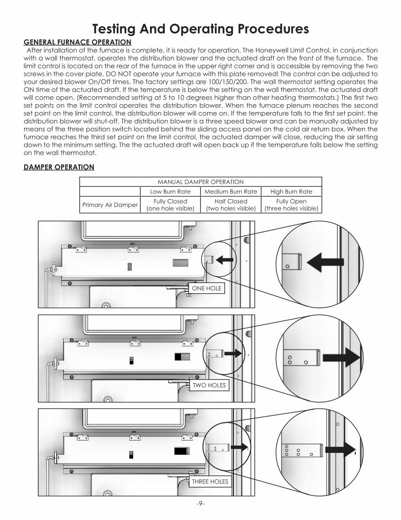
DAMPER OPERATION
Testing And Operating Procedures
MANUAL DAMPER OPERATIONLow Burn Rate Medium Burn Rate High Burn Rate
Primary Air Damper Fully Closed (one hole visible)
Half Closed (two holes visible)
Fully Open (three holes visible)
ONE HOLE
TWO HOLES
THREE HOLES

-10-
TESTING1. Check the actuated draft by turning the room thermostat up high enough so that the motorized draft opens.
Then lower the thermostat setting to ensure it closes off.2. Use a sheet of newspaper to test your draft by placing it inside the furnace and lighting it.
STARTING A WOOD FIREDO NOT BURN:1. Garbage;2. Lawn clippings or yard waste;3. Materials containing rubber, including tires;4. Materials containing plastic;5. Waste petroleum products, paints or paint thinners,
or asphalt products;6. Materials containing asbestos;7. Construction or demolition debris;8. Railroad ties or pressure-treated wood;
9. Manure or animal remains;10. Salt water drift wood or other previously salt water
saturated materials;11. Unseasoned wood; or12. Paper products, cardboard, plywood, or
particleboard. The prohibition against burning these materials does not prohibit the use of fire starters made from paper, cardboard, saw dust, wax and similar substances for the purpose of starting a fire in an affected wood heater.
Burning these materials may result in release of toxic fumes or render the heater ineffective and cause smoke. Dead wood lying on the forest floor should be considered wet, and requires full seasoning time. Standing dead wood can usually be considered to be about 2/3 seasoned. Splitting and stacking wood before it is stored accelerates drying time. Storing wood on an elevated surface from the ground and under a cover or covered area from rain or snow also accelerates drying time. A good indicator if wood is ready to burn is to check the piece ends. If there are cracks radiating in all directions from the center then the wood should be dry enough to burn. If your wood sizzles in the fire, even though the surface is dry, it may not be fully cured, and should be seasoned longerDo not burn manufactured logs made of wax impregnated sawdust or logs with any chemical additives.
Manufactured logs made of 100% compressed sawdust can be burned, but be careful burning too much of these logs at the same time. Start with one manufactured log and see how the stove reacts. You can increase the number of logs burned at a time to making sure the temperature never rises higher than 475 °F (246 °C) on a magnetic thermometer for installation on single wall stove pipes or 900 °F (482 °C) on a probe thermometer for installation on double wall stove pipe. The thermometer should be placed about 18” (457 mm) above the stove. Higher temperatures can lead to overheat and damage your stove.

-11-
CAUTION: Do not operate the furnace with out power connected to the unit. If there is a loss of electrical power the damper needs to be closed to the minimum burn rate and DO NOT add any more fuel to the fire
until power is restored.
DANGER: Risk of Fire or explosion, never use gasoline, never use gasoline, gasoline-type lantern fuel, kerosene, charcoal lighter fluid, or similar liquids to start or “freshen up” a fire in the furnace. Keep all such liquids well away from the furnace while it is in use.1. Open the fuel load door and light fire using kindling and several sheets of newspaper, then close the furnace
door. The furnace door should remain closed for 5 to 10 minutes in order to establish the fire. If the fire has established, you are ready to load the furnace.
CAUTION: To prevent flame and smoke spillage, the slide baffle must be pulled out and the fuel door must be cracked for ten seconds before being fully opened.Do not over fire your furnace! After you have become familiar with its operating, you should know how much
wood to use.2. Load the furnace, close the load door.3. The actuated draft cycles (opened & closed) on demand from the wall thermostat. Setting the U.S. Stove
thermostat four degrees higher than your existing thermostat is recommended. In operation, the power draft will remain open until the U.S. Stove thermostat temperature setting is reached. Then it will close to reduce combustion air. If the furnace looses power, the draft will automatically close. The desired burn rate for the unit can be adjusted with the slide damper for when the thermostat is calling for heat, but when the thermostat is not calling for heat the actuated draft will close the unit down to the minimum air setting.
CAUTION: To avoid excessive temperatures, do not operate with fuel door or ash pan open.
OPERATING NOTESThis wood heater has a manufacturer-set minimum low burn rate that must not be altered. It is against federal
regulations to alter this setting or otherwise operate this wood heater in a manner inconsistent with operating instructions in this manual.
VISIBLE SMOKEThe amount of visible smoke being produced can be an effective method of determining how efficiently the
combustion process is taking place at the given settings. Visible smoke consist of unburned fuel and moisture leaving your stove. Learn to adjust the air settings of your specific unit to produce the smallest amount of visible smoke. Wood that has not been seasoned properly and has a high wood moisture content will produce excess visible smoke and burn poorly. Use the included moisture meter to insure your wood has a 20% or less moisture content.

-12-
EFFICIENCYEfficiencies can be based on either the lower heating value (LHV) or the higher heating value (HHV) of the fuel.
The lower heating value is when water leaves the combustion process as a vapor, in the case of wood stoves the moisture in the wood being burned leaves the stove as a vapor. The higher heating value is when water leaves the combustion process completely condensed. In the case of wood stoves this would assume the exhaust gases are room temperature when leaving the system, and therefore calculations using this heating value consider the heat going up the chimney as lost energy. Therefore, efficiency calculated using the lower heating value of wood will be higher than efficiency calculated using the higher heating value. In the United States all wood stove efficiencies should be calculated using the higher heating value.The best way to achieve optimum efficiencies is to learn the burn characteristic of you appliance and burn well-
seasoned wood. Higher burn rates are not always the best heating burn rates; after a good fire is established a lower burn rate may be a better option for efficient heating. A lower burn rate slows the fl ow of usable heat out of the home through the chimney, and it also consumes less wood.• Do not operate with the fuel loading or ash removal doors open.• Do not operate with flue draft exceeding .06 in water column.• Do not store fuel or other combustible material within marked installation clearances.• Inspect and clean your flues and chimney regularly.• CAUTION: Hot Surfaces - Keep children away. Do not touch during operation. Maximum draft marked on
nameplate.• Equip your home with fire extinguishers and smoke detectors appropriately located.• Wood should be placed directly onto the brick of the furnace. Do not use additional grates and/or irons.• Do not allow ashes to build up higher than 2” above the brick.• Never allow the ashes in the ash pan to touch the grate section. REMOVE ASHES FREQUENTLY!• Be extremely careful when removing furnace ash pan; it can get very hot.• With new steel, there is a small amount of oil or dirt on the metal. You may smell an odor. This is normal during
the first operation. You may want to build a small fire in the furnace to “burn off” this dirt and oil before installing the duct work.
• The furnace is designed to burn air dried wood at a predetermined firing rate. Over firing could result in damage to the heat exchanger and cause dangerous operation. Over firing occurs when the ash door is left open during operation or a highly volatile fuel, i.e. large amounts of small kindling, is used. If any portion of the connector pipe glows orange or red, you are in an over-firing situation. Close all dampers.
• When tending the firebox always pull the baffle slide rod out prior to opening load door. Open load door slowly to avoid a “flash back”. After closing load door, push the baffle slide rod to the rear.
• In event of chimney fire, shut all draft controls and call your fire department immediately. Alert everyone in the house. If the fire is still burning vigorously, throw baking soda into firebox or discharge a fire extinguisher into the firebox. After chimney fire is over, completely inspect system for damage before further use.
• NEVER throw water on the fire or at the furnace, as rapidly expanding steam could result in a severe scalding.
• Slow fires: It is not recommended burning the furnace any more than necessary early in the fall and late spring, as you cannot keep the firebox hot enough (without overheating your home) to burn gases. Slow fires can cause excessive creosote build-up in smoke pipe, chimney and firebox.
• Inspect air filters regularly. The air filter should be changed at least every 30 days.• Check the fit on the load door. It must fit tightly. If it does not, check for deterioration or wear of the ceramic
rope seal. Replace defective seals.• In the event of a power failure, the furnace will not distribute heat to the home. We recommend the use of a
back-up generator, 2,000 watts minimum, for continued use until regular power is restored• Inspect flue pipes, flue pipe joints and flue pipe seals regularly to ensure that smoke and flue gases are not
drawn into, and circulated by, the air-circulation system.• CAUTION: clean out of the heat exchanger, flue pipe, chimney, and draft inducer if used, is especially
important at the end of the heating season to minimize corrosion during the summer months, caused by accumulated ash.
NOTE: For further information on using your furnace safely, obtain a copy of the National Fire Protection Association publication “Using Coal and Wood Stoves Safely.” NFPA NO. NW-8-1974. The address of the NFPA is 470 Atlantic Ave., Boston, Massachusetts 02210.
THIS IS A WOOD FURNACE AND SHOULD NOT BE ALTERED IN ANY WAY! DOING SO WILL VOID YOUR WARRANTY!

-13-
CREOSOTE - FORMATION AND NEED FOR REMOVALWhen wood is burned slowly, it produces tar and other organic vapors, which combine with expelled moisture
to form creosote. The creosote vapors condense in the relatively cool chimney flue of a slow-burning fire. As a result, creosote residue accumulates on the flue lining. When ignited, this creosote makes an extremely hot fire. The chimney should be inspected at least twice monthly during the heating season to determine if a creosote build-up has occurred. If creosote has accumulated, it should be removed to reduce the risk of a chimney fire.
OVER FIRINGAttempts to achieve heat output rates that exceed heater design specifications can result in permanent
damage to the heater. Whenever ashes get 3 to 4 inches deep in your firebox or ash pan, and when the fire has burned down and cooled, remove excess ashes. Leave an ash bed approximately 1 inch deep on the firebox bottom to help maintain a hot charcoal bed.
ASH REMOVAL AND DISPOSALAshes should be placed in a metal container with a tight-fitting lid. The closed container of ashes should be
placed on a noncombustible floor or on the ground, away from all combustible materials, pending final disposal. The ashes should be retained in the closed container until all cinders have thoroughly cooled.
SMOKE AND CO MONITORSBurning wood naturally produces smoke and carbon monoxide(CO) emissions. CO is a poisonous gas when
exposed to elevated concentrations for extended periods of time. While the modern combustion systems in heaters drastically reduce the amount of CO emitted out the chimney, exposure to the gases in closed or confined areas can be dangerous. Make sure your stove gaskets and chimney joints are in good working order and sealing properly to ensure unintended exposure. It is recommended that you use both smoke and CO monitors in areas having the potential to generate CO.
GASKETSIt is recommended that you change the door gasket (which makes your stove door air tight) once a year, in
order to insure good control over the combustion, maximum efficiency and security. To change the door gasket, simply remove the damaged one. Carefully clean the available gasket groove, apply a high temperature silicone sold for this purpose, and install the new gasket. You may light up your stove again approximately 24 hours after having completed this operation. This unit’s doors use a 3/8” diameter rope gasket.
OPERATIONAL TIPS• Get the appliance hot and establish a good coal bed before adjusting to a low burn rate(this may take 30
minutes or more depending on your wood)• Use smaller pieces of wood during start-up and a high burn rate to increase the stove temperature • Burn small, intense fires instead of large, slow burning fires when possible • Learn your appliance’s operating characteristics to obtain optimum performance.• Be considerate of the environment and only burn dry wood• Burning unseasoned wet wood only hurts your stoves efficiency and leads to accelerated creosote buildup
in your chimney.

-14-
Domestic Hot Water Coil Kit - Optional
DOMESTIC HOT WATER COIL
REAR WALL OF FIREBOX
TURN INSIDE NUTS UP TO END OF THREADS
1. NUT2. WASHER3. GASKET
2
3
45
6
ACCESS PANEL
1
This Furnace will accept the installation of a Domestic Hot Water Coil Kit. The U.S. Stove kit is a 1124 Water Coil and it may be purchased from your local dealer.1. Remove the access panel on the rear of the
furnace enclosure.2. With a utility knife, cut away a section of the
insulation directly behind the access panel.3. Remove the cover plate from the rear of the
furnace firebox.4. Place one nut on each end of the water coil
and thread each nut up to the end of the threads on the coil.
5. Insert the coil through the holes from the inside of the firebox. Install a gasket, washer and nut onto each end of the water coil. Tighten the nuts down securely to insure an air tight seal.
The installation is now ready to be plumbed to your existing hot water system. Choose one of the three methods described in the Hot Water Coil instructions.6. Remove knockouts from the access panel and
re-attach to the furnace enclosure.Have a qualified plumber connect your domestic
hot water pipe to the coil with the appropriate fittings.

-15-
Trouble Shooting And Problem SolvingProblem Solution
1. Smoke puffs from furnace
• Check chimney draft. Check for blocked chimney or flue pipe. Use mirror to check chimney clearance.
• Check ash pit — if it is too full, empty. • Make sure all of chimney mortar connections are airtight.• Check ash drawer. Make sure it’s airtight.• Check chimney for possible down-draft caused by taller surrounding trees or
objects. Correct with proper chimney vent cap.• Check the possibility of a cold chimney forcing cool gases backward.
Remedied by properly insulating chimney with non-combustible liner — non-combustible insulation.
• Fuel may be too green.• Make sure no other fuel burning devices are connected to the chimney
impairing the draft.• Check chimney draft, it should be .06 inches of water column. This service is
provided by a certified chimney sweep.
2. Inadequate heat being delivered to your home
• Check home insulation — is it adequate?• Check hook-up to furnace — is it installed correctly?• Cool air inlet may be inadequate.• Your wood fuel may be too low grade. Hardwoods are recommended.• Make sure your hot air duct (and other duct work) is airtight.• Is air to the blower available?
3. Excess smoke or flames coming out door when refueling
• Wait 15 seconds and open door SLOWLY — then refuel.• Check length of flue pipe to chimney.• Make sure chimney cap is not too close to the top of the chimney.• Check chimney draft — make sure chimney flue pipe is clean and chimney is of
adequate height.• Make sure you’re not suffocating the fire with excessive amounts of unburned
wood.• Slide baffle should be pulled out prior to load door opening.
4. Distribution blower vibrating • Tighten blower wheel to motor shaft.• Check for bad fan bearings.
5. Distribution blower continues to run or will not run
• Check fan limit or heat sensor and cable.• Check to see that blower is properly wired. (See Wiring and Assembly
Instructions).• Check fuse box or power source.• Check power supply.
6. Motorized draft stays open or will not close
• Check wiring.• Check thermostat or thermostat wire for short.• Make sure temperature is calling for heat.
7. Odor from first fire• The odor from new steel should disappear in a few hours.• If the odor remains, call you dealer immediately. A bad weld can cause a fume
leak.
8. Excessive Creosote
• Check the grade of wood you are burning. • Make sure your unit is serviced by its own proper chimney.• Check length of flue pipe and its connections.• Make sure you are burning the smallest, hottest fire to adequately heat your
home.• Also see Solutions to Problem number 1.
9. If the fire goes out or does not hold over night
• Poor Draft.• Incorrect damper settings.• More combustion air needed.• Ashes, if allowed to accumulate in the ash pit, will not allow passage of the
required air for combustion. Keep ash pit clean.• This furnace is not to be used with an automatic stoker unless so certified.

-16-
U.S. Wiring Diagram
SERVO MOTOR
1600CFMDISTRIBUTION
BLOWER

-17-
Parts List
In order to maintain warranty, components must be replaced using original manufacturers parts purchased through your dealer or directly from the appliance manufacturer. Use of third party components will void the warranty.
Door Insulation88271 1
Damper Assembly610651 1
Feed Door (Blank)40499 1
Damper Plate28212 1
Ac Laminated Pull Solenoid80753 1
Handle, Door (Drilled)891885 1
Inner Shield28191 1
Latch, E5 Cam W/Cup891865 1
Door Latch (C000022)23786 1
3/8” Rope Gasket88033 4 ft
Linkage Rod892848 1
Actuator Shield28211 1
Bottom Intake28195 1
Ashpan Weldment610498 1
Door Assembly610650 1
Port Support610899 1

-18-
Parts List
In order to maintain warranty, components must be replaced using original manufacturers parts purchased through your dealer or directly from the appliance manufacturer. Use of third party components will void the warranty.
Ash Door40818 1
Handle, Separable891884 1
Cover, Water Coil892796 1
5/8” Rope Gasket88066 3 ft
Assembly, Fan Center69651 1
Transition892797 1
Assembly, Ash Door610496 1
Handle Assembly891098 1
Blower Bottom892800 1
Door Latch86626 1
Handle, Spring (Lg-Nickel)891135 1
Bracket, Alignment25719 2
Mtg Brkt, Blower Box892794 2
Electrical Access Door25739 1
Handle, Cabinet Top891591 1
Harness, 3 Circuit Plug80586 1

-19-
Parts List
In order to maintain warranty, components must be replaced using original manufacturers parts purchased through your dealer or directly from the appliance manufacturer. Use of third party components will void the warranty.
Harness, 2 Circuit Receptacle80585 1
Electrical Box Cover25742 1
Blower g10-8 Direct Drive (DD)D2040115 1
Harness, 6 Circuit Receptacle80583 1
Electrical Box Body25743 1
Power Supply Cord80232 1
Blower Wrapper892799 1
80692Switch, 3-Position 1
Strain Relief80154 1
Blower Top892798 1
Harness, 3 Circuit Receptacle80584 1
Transformer, Fan Center80130 1
Cast Grate40605 1
Cable Chase892809 1
Fiber Board892760 2
Harness, 2 Circuit Plug80587 1

-20-
Parts List
In order to maintain warranty, components must be replaced using original manufacturers parts purchased through your dealer or directly from the appliance manufacturer. Use of third party components will void the warranty.
Motor 1/2 HP 4 SPD DDD2020008 1
Left Tube Carrier 28318 1
Gasket, Water Coil CoverC97999 1
Probe Access Panel25733 1
Tube (Ø7/32), Secondary Air86877 6
Mount, Flue Outlet28196 1
Half Firebrick891414A 14
1/8 Dia X 1-1/2 Cotter Pin83874 6
Inner Top28197 1
Firebrick (4-1/2 X 9) Pumice89066A 26
Limit Control80145 1
Cabinet Top610611 1
Panel, Insulation Top/Frnt88150 1
Inside Cover Plate24220 1
Panel, Insulation Top/Bk88152 1
Panel, Insulation Top/Mid88151 1

-21-
Parts List
In order to maintain warranty, components must be replaced using original manufacturers parts purchased through your dealer or directly from the appliance manufacturer. Use of third party components will void the warranty.
Stub Collar892853 1
Right Tube Carrier 28318 1
Rear Panel610612 1
Top Filler892806 1
D-Ring W/Clip83912 4
Hood, Front892804 1
CapacitorD2010040 1
Firebrick Layout
Harness, Receptacle80752 1
Stub Collar, 10”891868 1
Channel Liner28537 2
KAO Wool88275 1

-22-
Notes

-23-
It is recommended that your heating system is serviced regularly and that the appropriate Service Interval Record is completed.
SERVICE PROVIDERBefore completing the appropriate Service Record below, please ensure you have carried out the service
as described in the manufacturer’s instructions. Always use the manufacturer's specified spare part when replacement is necessary.
Service Record
Service 01 Date: _____________________Engineer Name: ________________________________License No.: ____________________________________Company: _____________________________________Telephone No.: _________________________________Stove Inspected: Chimney Swept:Items Replaced: ________________________________
Service 03 Date: _____________________Engineer Name: ________________________________License No.: ____________________________________Company: _____________________________________Telephone No.: _________________________________Stove Inspected: Chimney Swept:Items Replaced: ________________________________
Service 05 Date: _____________________Engineer Name: ________________________________License No.: ____________________________________Company: _____________________________________Telephone No.: _________________________________Stove Inspected: Chimney Swept:Items Replaced: ________________________________
Service 07 Date: _____________________Engineer Name: ________________________________License No.: ____________________________________Company: _____________________________________Telephone No.: _________________________________Stove Inspected: Chimney Swept:Items Replaced: ________________________________
Service 02 Date: _____________________Engineer Name: ________________________________License No.: ____________________________________Company: _____________________________________Telephone No.: _________________________________Stove Inspected: Chimney Swept:Items Replaced: ________________________________
Service 04 Date: _____________________Engineer Name: ________________________________License No.: ____________________________________Company: _____________________________________Telephone No.: _________________________________Stove Inspected: Chimney Swept:Items Replaced: ________________________________
Service 06 Date: _____________________Engineer Name: ________________________________License No.: ____________________________________Company: _____________________________________Telephone No.: _________________________________Stove Inspected: Chimney Swept:Items Replaced: ________________________________
Service 08 Date: _____________________Engineer Name: ________________________________License No.: ____________________________________Company: _____________________________________Telephone No.: _________________________________Stove Inspected: Chimney Swept:Items Replaced: ________________________________

How To Order Repair Parts
United States Stove Company227 Industrial Park RoadSouth Pittsburg, TN 37380
(800)-750-2723
This manual will help you obtain efficient, dependable service from the furnace, and enable you to order repair parts correctly.
Keep this manual in a safe place for future reference.
When placing an order or for warranty claims, please provide the following information found on the Certification Plate located inside the cabinet door.
Part Number ___________________________________________________________
Part Description ________________________________________________________
Model Number _________________________________________________________
Serial Number __________________________________________________________