owners guide to the dual plug ignition … 1 - owner's guide to the dual plug ignition system...
TRANSCRIPT
OWNERS GUIDE TO THE DUAL PLUG IGNITION SYSTEM
byTOM CUTTER
FORWARD
This guide would not have come about without the impetus and encouragement of manypeople, but the greatest creative force has been supplied by one man who will not realizea penny of profit from his endeavors in the field of Dual Plug Ignition for the BMWmotorcycles. Therefore, it only seems fitting to dedicate this book to Orlando Obediah(Oak) Okleshen, former Technical Editor of the BMW NEWS.
Also a special note of thanks goes to Udo Gietl for his years of patience and wisdom,given generously and freely, and for his special insight into things mechanical.
Tom CutterMay 8, 1981105 W. Hamilton AvenueEnglewood, N.J. 07631
Foreword to the 2003 Reprint
This document is a reprint of the original booklet which was published in 1981.My original intent for that booklet was to help riders understand the associatedproblems and procedures for dual plugging etc.Much of the information is now OBSOLETE and in some places INCORRECT.Nonetheless I understand that there are people who still want a copy for historicalpurposes.Readers are permitted to make one copy of this document for their personal use and alsoto distribute it FREE to anyone else who wants it. No reselling it. No republishing itwithout prior permission, please.
Tom CutterMay 2003
Reprint produced by William Slodysko and Ken Monro with permission from Tom Cutter.Cover artwork is a reproduction of the original by Richard Dalton

- 1 -
OWNER'S GUIDE TO THE DUAL PLUG IGNITION SYSTEM
CONGRATULATIONS on your decision to convert your BMW motorcycle to the DualPlug Ignition System (DPIS). This conversion will enhance your enjoyment of yourBMW by allowing you to use Regular-Grade fuel, reducing maintenance, andincreasing the resale value of your motorcycle.
This guide is intended as an "Owner's Manual" for the System, to assist you inmaintaining and fine-tuning the System to your needs and riding style. It is notintended to be a technical treatise on the subject, since this material is availablefrom other sources, including the manufacturers of the various components used inthe System. A valuable reference source on the System as applied to the BMWmotorcycle is the BMW NEWS, the monthly newsletter of the BMW MotorcycleOwners of America.
The System is discussed in an easy-to-read format in the November and December,1980, and May, 1981 issues of this publication. Reprints of these articles, andmembership information can be obtained from BMW NEWS, 2902 Eastwood, IowaCity, Iowa 52240. It is highly recommended that you obtain and read these articles inconjunction with this guide, to familiarize yourself with the basic function of theSystem, as well as to indicate some of the variations possible with the System.
This guide will deal with the System as described in the above-mentioned articles,although much of the information contained herein is applicable to many of thevariant systems now being offered.
- 2 -
This document is a reprint of the original 1981 booklet. Some information may be obsolete or incorrect.
For your convenience, a space is included in the back of this guide to record tuningsettings and results of variations as they affect performance or fuel economy. Thiswill assist you in obtaining the optimum results for your riding style and machine.
Wish you the best of luck and enjoyment with the System:
Tom Cutter
- 3 -
TABLE OF CONTENTS
INTRODUCTION ..................................................................................................... 1
DETONATION AND THE DUAL PLUG IGNITION SYSTEM ........................................ 4
DESCRIPTION OF THE DUAL PLUG IGNITION SYSTEM.......................................... 9
PREPARING CYCLINDER HEADS FOR DUAL PLUG IGNITION............................... 11
SPARK PLUG CROSS-REFERENCE CHARTS......................................................... 13
SERVICING THE DUAL PLUG IGNITION SYSTEM.................................................. 17A.) INSTALLING SPARK PLUGS .................................................................. 17B.) INSTALLING AND SETTING IGNITION POINTS...................................... 18C.) SETTING IGNITION TIMING FOR THE DPIS .......................................... 22D.) IGNITION COILS AND WIRES ............................................................... 25E.) IGNITION AMPLIFIER ........................................................................... 25F.) CARBURETOR ADJUSTMENT............................................................... 27G.) CARBURETOR JETTING....................................................................... 38
RECORD-KEEPING SECTION ............................................................................... 40
- 4 -
This document is a reprint of the original 1981 booklet. Some information may be obsolete or incorrect.
DETONATION AND THE DUAL PLUG IGNITION SYSTEM
An internal combustion engine creates usable power by the combustion (burning) of fuelto create gas pressure. By trapping this pressure and allowing it to work upon the piston,this energy is converted from heat into motion which is fed to the wheel via the powertrain (Crankshaft, transmission and driveshaft).
The stock BMW engine is limited in its ability to burn the fuel in a controlled andprogressive fashion, as is any internal combustion engine. As the fuel mixture burns, theremaining unburnt mixture is subjected to rapidly increasing temperature and resultantpressure. Since an increase in pressure in a closed container will cause a parallel increasein temperature, and vice-versa, a chain reaction develops wherein the fuel mixture wouldspontaneously self-ignite if it is not first consumed by the orderly flame started at thespark plug. In the BMW motorcycle engine, the spark plug is not centrally located in thecombustion chamber, so the flame front must travel a relatively long distance to consumethe fuel in the remotest reaches of the chamber. If the speed of this flame travel is tooslow, the rising temperature and pressure in the cylinder head will cause the mixture toself-ignite in an explosive fashion. This condition is known as "detonation", and iscommonly called "ping", or "knock". These names are derived from the sound thatemanates from the engine, similar to the sound of two metal objects being struck together.
In the most extreme cases, detonation can lead to severe engine damage from shock andoverheating. In less severe cases, loss of performance and fuel economy will occur becausethe energy released by the burning fuel is not controlled to work upon the piston, and islost as heat.
- 5 -To prevent detonation from occurring, oil companies add ingredients to gasoline toretard the progress of the chain reaction of increasing temperature and pressure.Fuels are tested in specially-designed test engines to measure their resistance todetonation. By making a quantative comparison of the test fuel against astandardized fuel called iso-octane, the detonation resistance of the fuel can beexpressed as an octane rating. The octane rating of currently-available automotivefuels ranges from 85 to 96 PON (Pump Octane Number). By U.S. law, this numberwill be displayed on the pump when the fuel is offered for sale.
For various reasons, high-octane fuel is being phased out of existence in the U.S.This situation has created a serious problem for owners of BMW motorcyclesproduced between 1970 and 1979, since these models were designed to be operatedon a steady diet of 94 octane (PON) premium-grade fuel. In an effort to attractperformance-oriented buyers, BMW opted to use high compression ratios whichrequired high-octane fuel. Now, however, the owners of these high-compressionmotorcycles are faced with the dilemma of not being able to find ready sources ofhigh-octane fuel, especially when travelling. This problem has led many BMW ownersto seek alternatives to high-octane fuel for their motorcycles.
Over the last decade, there have been many alternatives offered to the BMW owner toovercome the octane problem. Some of these solutions are; compression reduction,octane boosters and fuel additives, fuel mixing, and, most recently, the Dual PlugIgnition System. Each of these alternatives is discussed below.
- 6 -
This document is a reprint of the original 1981 booklet. Some information may be obsolete or incorrect.
BMW has suggested compression ratio reduction as a solution to the octaneproblem for many years. This is done by adding thick shims at the cylinder base toincrease the volume of the combustion chamber and reduce the compression ratio.Since these shims resemble, and serve secondarily as, gaskets, they are commonlyreferred to as "low-octane gaskets". This solution was readily available to BMWsince the company builds many low-compression engines for military, police andother applications in different markets. There are many machines in the U.S. thathave been converted in this manner, and if you own a machine that was purchasedsecondhand, it is possible that it was converted by the previous owner. There aredrawbacks to this solution, however, the greatest of which is a loss of power andfuel economy which can range from mild to severe depending on tuning factors andriding style. Also, lower compression engines tend to exhaust at highertemperatures, which lends to increased operating temperatures and reducedefficiency. This combination of effects can lead to rapid carbon buildup in thecombustion chamber, which will raise the effective compression ratio and hinderheat transfer, leading to detonation problems after extended operation. For thisreason, many low-compression conversions were unsuccessful from the standpointof octane requirement reduction.

- 7 -
Another commonly-used solution to the octane problem is the mixing of additives or"octane boosters" to the fuel to raise the detonation resistance of the fuel. Due to thehigh cost of these substances, coupled with the inconvenience and risk inherent incarrying them while touring, their practical application is limited. While thesesubstances will raise the octane of the fuel mixture if mixed correctly, there havebeen reports of carburetor float saturation and fuel leakage associated with their usein the BMW motorcycle.
It is possible to mix leaded regular-grade fuel with the now-available unleadedpremium grades to obtain a mixture whose octane level will be in the vicinity of 92.5PON. For those BMW's which will run well on this octane level, this is a practicalalternative, if the rider is willing to contend with the inconvenience of the mixingchores. Since no modification is required on the machine, the economy factor isfavorable as well. This process will not work, however, in some conditions, such ashigh ambient temperatures, high loads, or excessive carbon buildup in the engine.The R60/5 and R60/6 models will seldom run well on this mix, due to the camshaftgrind used on these models, which raises the effective compression ratio and willaggravate the detonation problem.
The Dual Plug Ignition System has its historical roots in aircraft and racingapplications, where its ability to control detonation and boost power output havebeen well proven.
- 8 -
This document is a reprint of the original 1981 booklet. Some information may be obsolete or incorrect.
These benefits can also be applied to street riding, now that high-octane fuel isbecoming scarce. The System will also offer other benefits, including improved fueleconomy, cleaner running with less carbon deposits in the engine, and a modestperformance boost. Fuels with octane ratings as low as 87 can be used, even in theR60 models, without detonation. If the system is used for performance reasons, it willpermit the use of compression ratios and camshaft grinds that would be otherwiseimpractical for street use. It is important to note, however, that the System will notcure or cover up other engine maladies, which should be corrected before themodification is performed, or while it is in progress.
There are many vendors offering the System in various forms at this time, and pricesand equipment offered can vary tremendously, so the prospective buyer shouldcarefully analyze his needs, and choose accordingly. Shortcuts in the basicconversion will almost certainly result in the loss of some (or all) of the potentialbenefits of the System.
This guide will address the use of the System primarily for detonation control, andsecondarily for improving fuel economy and performance. Only 1970-1979 BMWmodels are covered, since these are the models most frequently converted. The nextchapter will describe the components of the System, and indicate some of the basicfunctions of each component.
- 9 -
DESCRIPTION OF THE DUAL PLUG IGNITION SYSTEM
As its name suggests, the primary function of the Dual Plug Ignition System is toprovide and fire a second spark plug in each combustion chamber. To accomplishthis objective, two basic jobs are required. The first is to prepare the cylinderhead to accept the additional spark plug, and the second is to modify the ignitionsystem to deliver adequate spark to fire the added plug. Since these two jobsrequire some disassembly and modification work, they provide an excellentopportunity to improve upon existing parts to realize the maximum benefit fromthe conversion. Due to the nature of the work involved, it is recommended toleave it to a person who has a solid understanding of engine operation and repairtechniques. The machining required to install the additional spark plug should betrusted to a shop that has experience with this modification, since even a smallerror could ruin the cylinder head. The modification of the ignition system isrelatively straight-forward, but it should be done in a professional and workman-like manner to insure reliability.
The System consists of two additional spark plugs located in the "bottom" ofthe cylinder head, opposite the existing spark plugs, two high-energy,dual-output ignition coils with racing-type copper-core spark wires, and anignition amplifier which is triggered by the stock points. In addition to thesecomponents, it is necessary to re-adjust ignition timing and carburetor
- 10 -
This document is a reprint of the original 1981 booklet. Some information may be obsolete or incorrect.
settings to accommodate the change. Some experimentation with these settings willhelp you to tailor the System to your needs. Initial settings are included in laterchapters. Keep detailed notes on all changes and settings for maximum results.
The following chapters will cover installation and maintenance procedures for eachcomponent of the System. It is suggested to use a BMW Repair Manual inconjunction with this guide. If you are hesitant to attempt this modification yourself,this guide should be used by the person who you appoint to perform the modificationfor you.
"The only reason some people get lost in thoughtis because it's unfamiliar territory" ---Paul Fixx
- 11 -
PREPARING CYLINDER HEADS FOR DUAL PLUG IGNITION
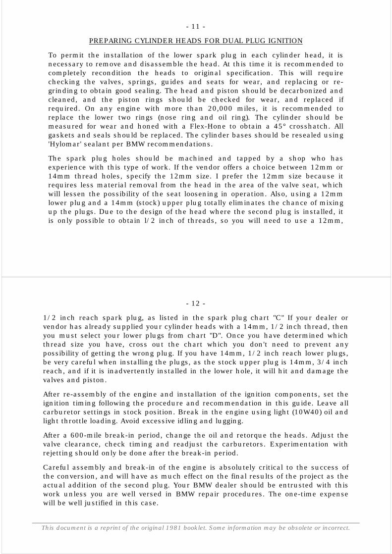
To permit the installation of the lower spark plug in each cylinder head, it isnecessary to remove and disassemble the head. At this time it is recommended tocompletely recondition the heads to original specification. This will requirechecking the valves, springs, guides and seats for wear, and replacing or re-grinding to obtain good sealing. The head and piston should be decarbonized andcleaned, and the piston rings should be checked for wear, and replaced ifrequired. On any engine with more than 20,000 miles, it is recommended toreplace the lower two rings (nose ring and oil ring). The cylinder should bemeasured for wear and honed with a Flex-Hone to obtain a 45° crosshatch. Allgaskets and seals should be replaced. The cylinder bases should be resealed using'Hylomar' sealant per BMW recommendations.
The spark plug holes should be machined and tapped by a shop who hasexperience with this type of work. If the vendor offers a choice between 12mm or14mm thread holes, specify the 12mm size. I prefer the 12mm size because itrequires less material removal from the head in the area of the valve seat, whichwill lessen the possibility of the seat loosening in operation. Also, using a 12mmlower plug and a 14mm (stock) upper plug totally eliminates the chance of mixingup the plugs. Due to the design of the head where the second plug is installed, itis only possible to obtain l/2 inch of threads, so you will need to use a 12mm,
- 12 -
This document is a reprint of the original 1981 booklet. Some information may be obsolete or incorrect.
1/2 inch reach spark plug, as listed in the spark plug chart "C" If your dealer orvendor has already supplied your cylinder heads with a 14mm, 1/2 inch thread, thenyou must select your lower plugs from chart "D". Once you have determined whichthread size you have, cross out the chart which you don't need to prevent anypossibility of getting the wrong plug. If you have 14mm, 1/2 inch reach lower plugs,be very careful when installing the plugs, as the stock upper plug is 14mm, 3/4 inchreach, and if it is inadvertently installed in the lower hole, it will hit and damage thevalves and piston.
After re-assembly of the engine and installation of the ignition components, set theignition timing following the procedure and recommendation in this guide. Leave allcarburetor settings in stock position. Break in the engine using light (10W40) oil andlight throttle loading. Avoid excessive idling and lugging.
After a 600-mile break-in period, change the oil and retorque the heads. Adjust thevalve clearance, check timing and readjust the carburetors. Experimentation withrejetting should only be done after the break-in period.
Careful assembly and break-in of the engine is absolutely critical to the success ofthe conversion, and will have as much effect on the final results of the project as theactual addition of the second plug. Your BMW dealer should be entrusted with thiswork unless you are well versed in BMW repair procedures. The one-time expensewill be well justified in this case.
- 13 -
SPARK PLUG CROSS REFERENCE CHARTS
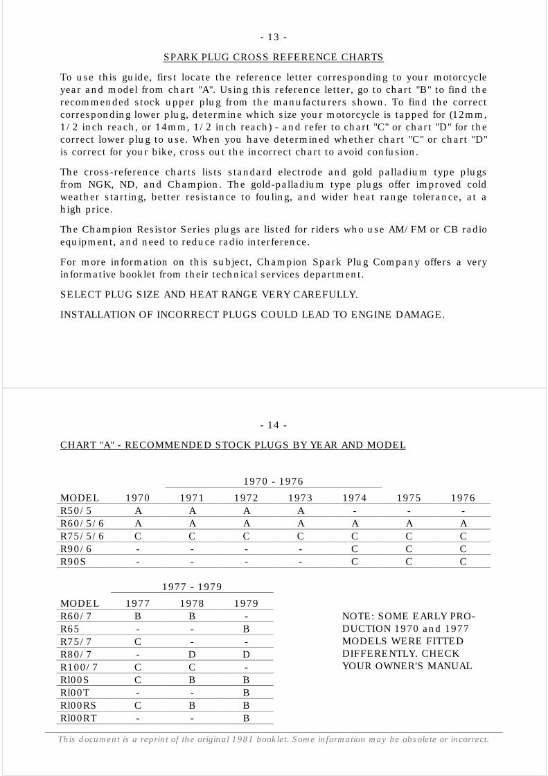
To use this guide, first locate the reference letter corresponding to your motorcycleyear and model from chart "A". Using this reference letter, go to chart "B" to find therecommended stock upper plug from the manufacturers shown. To find the correctcorresponding lower plug, determine which size your motorcycle is tapped for (12mm,1/2 inch reach, or 14mm, 1/2 inch reach) - and refer to chart "C" or chart "D" for thecorrect lower plug to use. When you have determined whether chart "C" or chart "D"is correct for your bike, cross out the incorrect chart to avoid confusion.
The cross-reference charts lists standard electrode and gold palladium type plugsfrom NGK, ND, and Champion. The gold-palladium type plugs offer improved coldweather starting, better resistance to fouling, and wider heat range tolerance, at ahigh price.
The Champion Resistor Series plugs are listed for riders who use AM/FM or CB radioequipment, and need to reduce radio interference.
For more information on this subject, Champion Spark Plug Company offers a veryinformative booklet from their technical services department.
SELECT PLUG SIZE AND HEAT RANGE VERY CAREFULLY.
INSTALLATION OF INCORRECT PLUGS COULD LEAD TO ENGINE DAMAGE.
- 14 -
This document is a reprint of the original 1981 booklet. Some information may be obsolete or incorrect.
CHART "A" - RECOMMENDED STOCK PLUGS BY YEAR AND MODEL
1970 - 1976MODEL 1970 1971 1972 1973 1974 1975 1976R50/5 A A A A - - -R60/5/6 A A A A A A AR75/5/6 C C C C C C CR90/6 - - - - C C CR90S - - - - C C C
1977 - 1979MODEL 1977 1978 1979R60/7 B B -R65 - - BR75/7 C - -R80/7 - D DR100/7 C C -Rl00S C B BRl00T - - BRl00RS C B BRl00RT - - B
NOTE: SOME EARLY PRO-DUCTION 1970 and 1977MODELS WERE FITTEDDIFFERENTLY. CHECKYOUR OWNER'S MANUAL
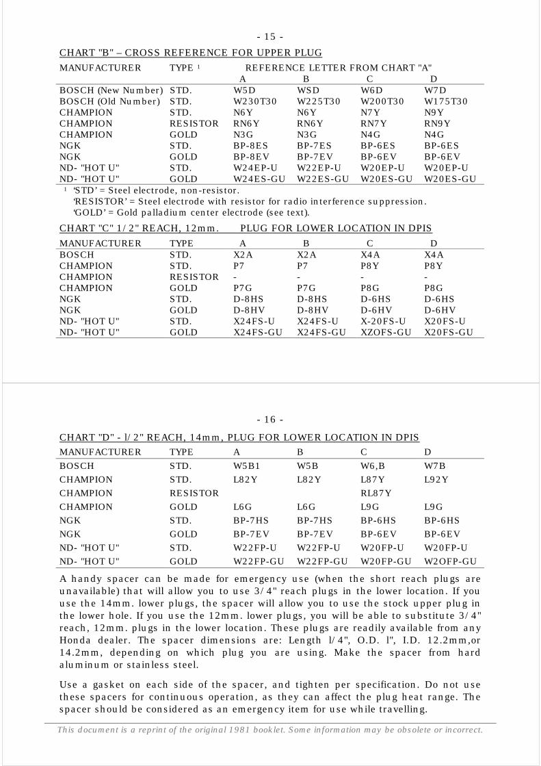
- 15 -CHART "B" – CROSS REFERENCE FOR UPPER PLUGMANUFACTURER TYPE 1 REFERENCE LETTER FROM CHART "A"
A B C DBOSCH (New Number) STD. W5D WSD W6D W7DBOSCH (Old Number) STD. W230T30 W225T30 W200T30 W175T30CHAMPION STD. N6Y N6Y N7Y N9YCHAMPION RESISTOR RN6Y RN6Y RN7Y RN9YCHAMPION GOLD N3G N3G N4G N4GNGK STD. BP-8ES BP-7ES BP-6ES BP-6ESNGK GOLD BP-8EV BP-7EV BP-6EV BP-6EVND- "HOT U" STD. W24EP-U W22EP-U W20EP-U W20EP-UND- "HOT U" GOLD W24ES-GU W22ES-GU W20ES-GU W20ES-GU
1 ‘STD’ = Steel electrode, non-resistor.‘RESISTOR’ = Steel electrode with resistor for radio interference suppression.‘GOLD’ = Gold palladium center electrode (see text).
CHART "C" 1/2" REACH, 12mm. PLUG FOR LOWER LOCATION IN DPISMANUFACTURER TYPE A B C DBOSCH STD. X2A X2A X4A X4ACHAMPION STD. P7 P7 P8Y P8YCHAMPION RESISTOR - - - -CHAMPION GOLD P7G P7G P8G P8GNGK STD. D-8HS D-8HS D-6HS D-6HSNGK GOLD D-8HV D-8HV D-6HV D-6HVND- "HOT U" STD. X24FS-U X24FS-U X-20FS-U X20FS-UND- "HOT U" GOLD X24FS-GU X24FS-GU XZOFS-GU X20FS-GU
- 16 -
This document is a reprint of the original 1981 booklet. Some information may be obsolete or incorrect.
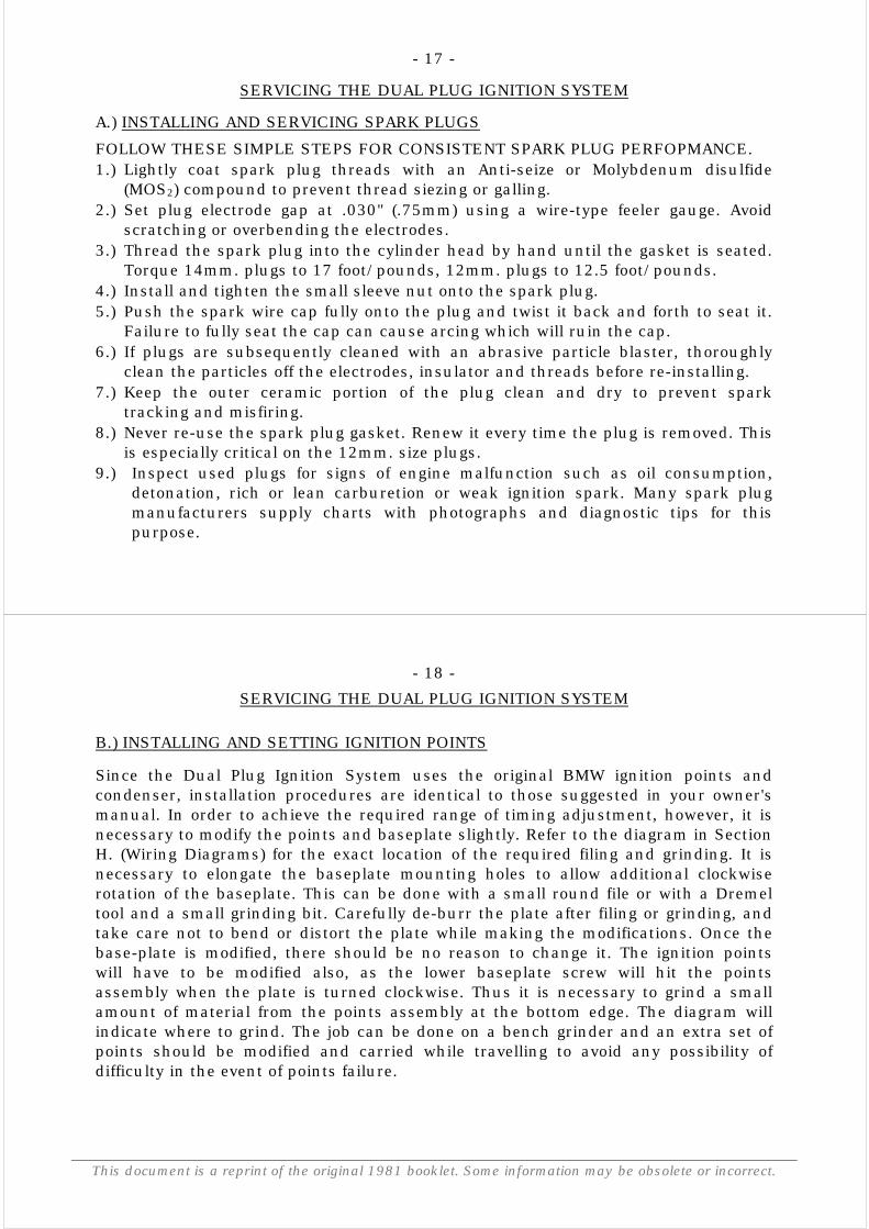
CHART "D" - l/2" REACH, 14mm, PLUG FOR LOWER LOCATION IN DPISMANUFACTURER TYPE A B C DBOSCH STD. W5B1 W5B W6,B W7BCHAMPION STD. L82Y L82Y L87Y L92YCHAMPION RESISTOR RL87YCHAMPION GOLD L6G L6G L9G L9GNGK STD. BP-7HS BP-7HS BP-6HS BP-6HSNGK GOLD BP-7EV BP-7EV BP-6EV BP-6EVND- "HOT U" STD. W22FP-U W22FP-U W20FP-U W20FP-UND- "HOT U" GOLD W22FP-GU W22FP-GU W20FP-GU W2OFP-GU
A handy spacer can be made for emergency use (when the short reach plugs areunavailable) that will allow you to use 3/4" reach plugs in the lower location. If youuse the 14mm. lower plugs, the spacer will allow you to use the stock upper plug inthe lower hole. If you use the 12mm. lower plugs, you will be able to substitute 3/4"reach, 12mm. plugs in the lower location. These plugs are readily available from anyHonda dealer. The spacer dimensions are: Length l/4", O.D. l", I.D. 12.2mm,or14.2mm, depending on which plug you are using. Make the spacer from hardaluminum or stainless steel.
Use a gasket on each side of the spacer, and tighten per specification. Do not usethese spacers for continuous operation, as they can affect the plug heat range. Thespacer should be considered as an emergency item for use while travelling.
- 17 -
SERVICING THE DUAL PLUG IGNITION SYSTEM
A.) INSTALLING AND SERVICING SPARK PLUGS
FOLLOW THESE SIMPLE STEPS FOR CONSISTENT SPARK PLUG PERFOPMANCE.1.) Lightly coat spark plug threads with an Anti-seize or Molybdenum disulfide
(MOS2) compound to prevent thread siezing or galling.2.) Set plug electrode gap at .030" (.75mm) using a wire-type feeler gauge. Avoid
scratching or overbending the electrodes.3.) Thread the spark plug into the cylinder head by hand until the gasket is seated.
Torque 14mm. plugs to 17 foot/pounds, 12mm. plugs to 12.5 foot/pounds.4.) Install and tighten the small sleeve nut onto the spark plug.5.) Push the spark wire cap fully onto the plug and twist it back and forth to seat it.
Failure to fully seat the cap can cause arcing which will ruin the cap.6.) If plugs are subsequently cleaned with an abrasive particle blaster, thoroughly
clean the particles off the electrodes, insulator and threads before re-installing.7.) Keep the outer ceramic portion of the plug clean and dry to prevent spark
tracking and misfiring.8.) Never re-use the spark plug gasket. Renew it every time the plug is removed. This
is especially critical on the 12mm. size plugs.9.) Inspect used plugs for signs of engine malfunction such as oil consumption,
detonation, rich or lean carburetion or weak ignition spark. Many spark plugmanufacturers supply charts with photographs and diagnostic tips for thispurpose.
- 18 -
This document is a reprint of the original 1981 booklet. Some information may be obsolete or incorrect.
SERVICING THE DUAL PLUG IGNITION SYSTEM
B.) INSTALLING AND SETTING IGNITION POINTS
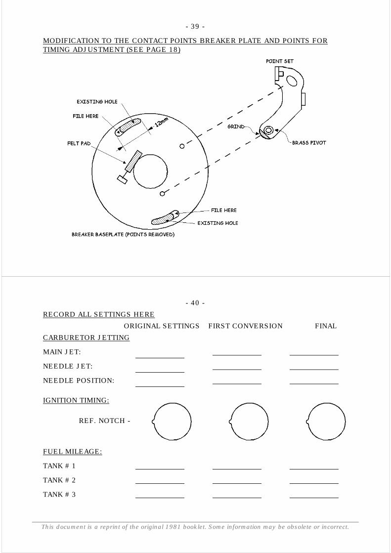
Since the Dual Plug Ignition System uses the original BMW ignition points andcondenser, installation procedures are identical to those suggested in your owner'smanual. In order to achieve the required range of timing adjustment, however, it isnecessary to modify the points and baseplate slightly. Refer to the diagram in SectionH. (Wiring Diagrams) for the exact location of the required filing and grinding. It isnecessary to elongate the baseplate mounting holes to allow additional clockwiserotation of the baseplate. This can be done with a small round file or with a Dremeltool and a small grinding bit. Carefully de-burr the plate after filing or grinding, andtake care not to bend or distort the plate while making the modifications. Once thebase-plate is modified, there should be no reason to change it. The ignition pointswill have to be modified also, as the lower baseplate screw will hit the pointsassembly when the plate is turned clockwise. Thus it is necessary to grind a smallamount of material from the points assembly at the bottom edge. The diagram willindicate where to grind. The job can be done on a bench grinder and an extra set ofpoints should be modified and carried while travelling to avoid any possibility ofdifficulty in the event of points failure.
- 19 -
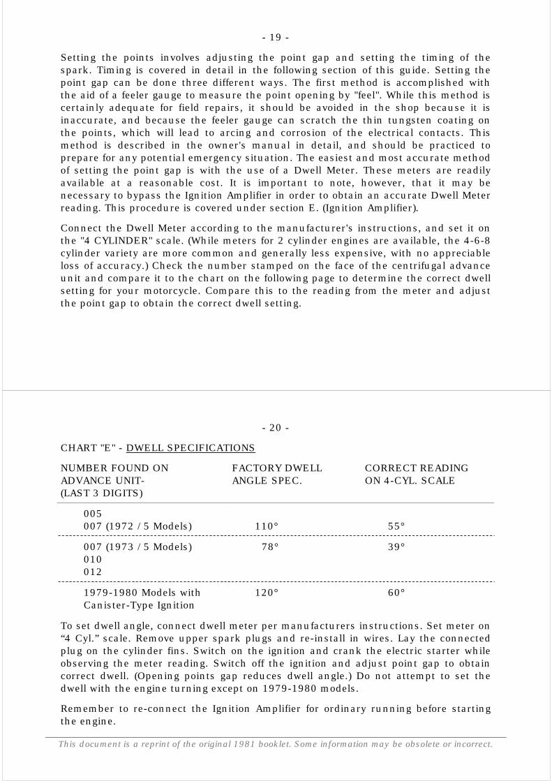
Setting the points involves adjusting the point gap and setting the timing of thespark. Timing is covered in detail in the following section of this guide. Setting thepoint gap can be done three different ways. The first method is accomplished withthe aid of a feeler gauge to measure the point opening by "feel". While this method iscertainly adequate for field repairs, it should be avoided in the shop because it isinaccurate, and because the feeler gauge can scratch the thin tungsten coating onthe points, which will lead to arcing and corrosion of the electrical contacts. Thismethod is described in the owner's manual in detail, and should be practiced toprepare for any potential emergency situation. The easiest and most accurate methodof setting the point gap is with the use of a Dwell Meter. These meters are readilyavailable at a reasonable cost. It is important to note, however, that it may benecessary to bypass the Ignition Amplifier in order to obtain an accurate Dwell Meterreading. This procedure is covered under section E. (Ignition Amplifier).
Connect the Dwell Meter according to the manufacturer's instructions, and set it onthe "4 CYLINDER" scale. (While meters for 2 cylinder engines are available, the 4-6-8cylinder variety are more common and generally less expensive, with no appreciableloss of accuracy.) Check the number stamped on the face of the centrifugal advanceunit and compare it to the chart on the following page to determine the correct dwellsetting for your motorcycle. Compare this to the reading from the meter and adjustthe point gap to obtain the correct dwell setting.
- 20 -
This document is a reprint of the original 1981 booklet. Some information may be obsolete or incorrect.
CHART "E" - DWELL SPECIFICATIONS
NUMBER FOUND ONADVANCE UNIT-(LAST 3 DIGITS)
FACTORY DWELLANGLE SPEC.
CORRECT READINGON 4-CYL. SCALE
005007 (1972 /5 Models) 110° 55°
007 (1973 /5 Models)010012
78° 39°
1979-1980 Models withCanister-Type Ignition
120° 60°
To set dwell angle, connect dwell meter per manufacturers instructions. Set meter on“4 Cyl.” scale. Remove upper spark plugs and re-install in wires. Lay the connectedplug on the cylinder fins. Switch on the ignition and crank the electric starter whileobserving the meter reading. Switch off the ignition and adjust point gap to obtaincorrect dwell. (Opening points gap reduces dwell angle.) Do not attempt to set thedwell with the engine turning except on 1979-1980 models.
Remember to re-connect the Ignition Amplifier for ordinary running before startingthe engine.
- 21 -The point opening can also be adjusted with a dial indicator set to measure the travelon the movable contact point. Use a solid mounting fixture and make sure that theindicator pointer is set in the direction of point travel. Rotate the engine with an allenwrench fitted in the alternator bolt, and adjust the point opening to .016" as specifiedby BMW.The above method will also show any runout in the camshaft tip, which is the causeof the "double image" seen when using a strobe timing light on the flywheel marks. Ifthe point opening is set to .016" on one side, and the other side does not open thesame amount, the runout should be corrected. To do this, remove the centrifugaladvance unit and place the dial indicator on the cam tip to find the "high spot". Usinga small plastic mallet, tap the shaft (NOT the threaded portion!) to straighten it.Proceed slowly and gently until there is .001" or less runout.When reinstalling the advance unit, locate the unit on the flat spot ground on thecam, then hold it counterclockwise gently with an adjustable wrench fitted on therectangular portion, while gently tightening the retaining nut. The nut should betorqued to 5.5 foot/pounds. Use extreme care in this entire operation, as a heavyhand can cause some very expensive damage. Once the runout is minimized at thecam tip, there is little else that can be done to correct any remaining timingvariation. maximum allowable variation is 3º, or the distance between the "S" markson the flywheel.As you can see, each of the three methods of adjusting the point gap is useful indifferent situations, so it is recommended that you become proficient at all of themethods.
- 22 -
This document is a reprint of the original 1981 booklet. Some information may be obsolete or incorrect.
SERVICING THE DUAL PLUG IGNITION SYSTEM
C.) SETTING IGNITION TIMING FOR THE DUAL PLUG IGNITION SYSTEM
Ignition timing must be set so that the spark occurs in time to allow the mixture toreach its full energy output as the piston begins its downward travel. Since the DualPlug Ignition System allows the flame propagation rate to be greatly increased, thetime required to burn the fuel mixture is reduced. For this reason, it is necessary toreadjust the ignition timing to have the spark occur later. The exact amount ofchange varies depending on bore size, ignition spark energy, fuel mixture strength,and engine temperature and RPM.
On the BMW motorcycle the ignition timing is adjusted to varying engine RPM bymeans of a centrifugal advance unit. Since 1970, BMW has changed thecharacteristics of this unit several times for various reasons, as evidenced by thechart "E" on page 20. For adjustment to suit the combustion behavior of the DualPlug Ignition System, the early unit used on 1970 and 1971 /5 models, marked "005"is not suitable and should be replaced with the latest 1978 unit marked "012" (BMWpart number 12 11 1 357 626). All of the later units are adaptable to the System,with proper adjustment.
For street use with the Dual Plug Ignition System, we need to
- 23 -
have the spark occur at 21-25° BTDC, at full advance. This setting will offer a goodcompromise for easy starting, mid-range power, and good fuel mileage. Since theBMW centrifugal advance unit has a total control range of 25° (26° on 1979 and 1980models), setting the timing (static) on the "OT" mark will give the proper full advancecurve. The larger bore engines (900 and 1000cc.) tend to prefer a slightly moreretarded setting, 2-3° ATDC. The R65 engine, having a shorter stroke, andconsequently different flame propagation characteristics, runs well when the statictiming is set at 3° BTDC.
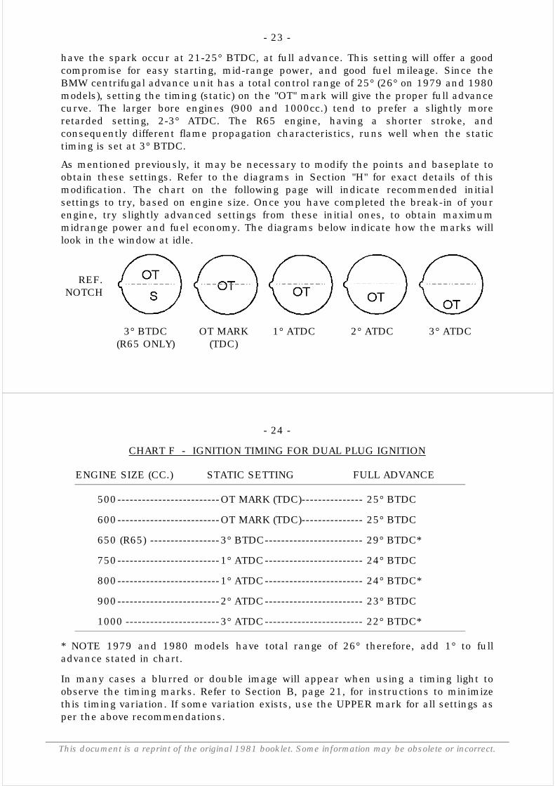
As mentioned previously, it may be necessary to modify the points and baseplate toobtain these settings. Refer to the diagrams in Section "H" for exact details of thismodification. The chart on the following page will indicate recommended initialsettings to try, based on engine size. Once you have completed the break-in of yourengine, try slightly advanced settings from these initial ones, to obtain maximummidrange power and fuel economy. The diagrams below indicate how the marks willlook in the window at idle.
REF.NOTCH
3° BTDC(R65 ONLY)
OT MARK(TDC)
1° ATDC 2° ATDC 3° ATDC
- 24 -
This document is a reprint of the original 1981 booklet. Some information may be obsolete or incorrect.
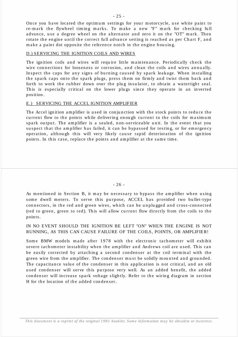
CHART F - IGNITION TIMING FOR DUAL PLUG IGNITION
ENGINE SIZE (CC.) STATIC SETTING FULL ADVANCE
500-------------------------OT MARK (TDC)--------------- 25° BTDC
600-------------------------OT MARK (TDC)--------------- 25° BTDC
650 (R65) -----------------3° BTDC------------------------ 29° BTDC*
750-------------------------1° ATDC------------------------ 24° BTDC
800-------------------------1° ATDC------------------------ 24° BTDC*
900-------------------------2° ATDC------------------------ 23° BTDC
1000 -----------------------3° ATDC------------------------ 22° BTDC*
* NOTE 1979 and 1980 models have total range of 26° therefore, add 1° to fulladvance stated in chart.
In many cases a blurred or double image will appear when using a timing light toobserve the timing marks. Refer to Section B, page 21, for instructions to minimizethis timing variation. If some variation exists, use the UPPER mark for all settings asper the above recommendations.
- 25 -Once you have located the optimum settings for your motorcycle, use white paint tore-mark the flywheel timing marks. To make a new "F" mark for checking fulladvance, use a degree wheel on the alternator and zero it on the "OT" mark. Thenrotate the engine until the correct full advance setting is reached as per Chart F, andmake a paint dot opposite the reference notch in the engine housing.
D.) SERVICING THE IGNITION COILS AND WIRES
The ignition coils and wires will require little maintenance. Periodically check thewire connections for looseness or corrosion, and clean the coils and wires annually.Inspect the caps for any signs of burning caused by spark leakage. When installingthe spark caps onto the spark plugs, press them on firmly and twist them back andforth to work the rubber down over the plug insulator, to obtain a watertight seal.This is especially critical on the lower plugs since they operate in an invertedposition.
E.) SERVICING THE ACCEL IGNITION AMPLIFIER
The Accel ignition amplifier is used in conjunction with the stock points to reduce thecurrent flow to the points while delivering enough current to the coils for maximumspark output. The amplifier is a sealed, non-serviceable unit. In the event that yoususpect that the amplifier has failed, it can be bypassed for testing, or for emergencyoperation, although this will very likely cause rapid deterioration of the ignitionpoints. In this case, replace the points and amplifier at the same time.
- 26 -
This document is a reprint of the original 1981 booklet. Some information may be obsolete or incorrect.
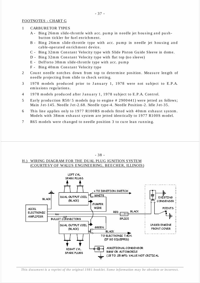
As mentioned in Section B, it may be necessary to bypass the amplifier when usingsome dwell meters. To serve this purpose, ACCEL has provided two bullet-typeconnectors, in the red and green wires, which can be unplugged and cross-connected(red to green, green to red). This will allow current flow directly from the coils to thepoints.
IN NO EVENT SHOULD THE IGNITION BE LEFT "ON" WHEN THE ENGINE IS NOTRUNNING, AS THIS CAN CAUSE FAILURE OF THE COILS, POINTS, OR AMPLIFIER!
Some BMW models made after 1978 with the electronic tachometer will exhibitsevere tachometer instability when the amplifier and Andrews coil are used. This canbe easily corrected by attaching a second condenser at the coil terminal with thegreen wire from the amplifier. The condenser must be solidly mounted and grounded.The capacitance value of the condenser in this application is not critical, and an oldused condenser will serve this purpose very well. As an added benefit, the addedcondenser will increase spark voltage slightly. Refer to the wiring diagram in sectionH for the location of the added condenser.
- 27 -
SERVICING THE DUAL PLUG IGNITION SYSTEM
F.) CARBURETOR ADJUSTMENT
Carburetor adjustment is the final step in engine tuning. All other adjustments, i.e.,valves, point gap, timing, plug gap and oil change should be done before any attemptis made to adjust the carburetors. Be sure that the carburetors are clean, i.e., free ofwater, dirt or stale fuel, and that the choke is fully off. The engine should be atnormal operating temperature, after a 5-10 minute ride, and cooling air should beprovided to the cylinders and heads by means of a fan.
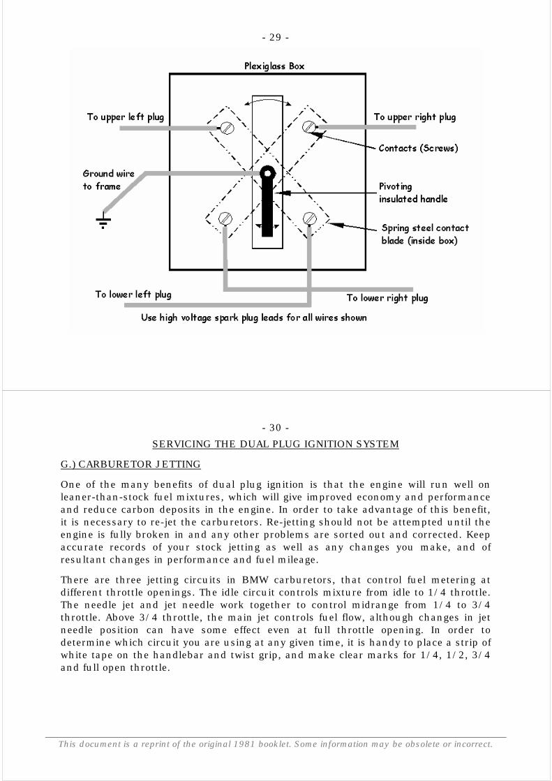
To adjust the carburetors, it is necessary to be able to shut off the spark to onecylinder at a time. Do not pull off the spark caps for this purpose, as damage couldresult to the coils and wires. Also, this method poses the hazard of possibleelectrocution to the adjustor. The spark must be grounded by means of a switchsuch as the Equalizer. This device can be homemade by following the sketch below,or an Equalizer for dual plug systems can be purchased from: ABC Enterprises, Box18016, Rochester, N.Y. 14618. Once you have a device to short out the spark, youcan proceed with the actual adjustment. Refer to your BMW owner's manual forclarification of this procedure.
Set the throttle at the idle position and shut out the right cylinder. Working on theleft carburetor, adjust the idle mixture screw to obtain the strongest running. Lowerthe idle speed with the idle speed screw and re-check the mixture adjustment.Repeat this adjustment until the left cylinder runs strongly at 450 - 550 RPM.
- 28 -
This document is a reprint of the original 1981 booklet. Some information may be obsolete or incorrect.
Now shut out the left cylinder and repeat the adjustment on the right carburetor toobtain the same idle speed. With both cylinders running, idle speed should be steadybetween 950 and 1050 RPM. By alternately shutting out each cylinder, check thatthey are running at the same speed. The idle adjustment is now set and should notbe changed. To synchronize the throttle cables, adjust the cable adjusters to provide1-2mm free play in each cable, then shut out the left cylinder. With just the rightcylinder running, lock the throttle at a steady 1500 RPM. Leave the throttle in thisposition and switch the left cylinder on, and adjust the cable to obtain 1500 RPM,and lock the adjuster nut. Switch each cylinder on and off alternately to check thatthey are both pulling the same RPM. To double check, bring the RPM up to 3500 onone cylinder and alternately check that both still pull the same speed. If there is agross difference at this RPM level, suspect a kinked cable or ruptured diaphragm asthe culprit. Correct this condition and repeat the adjustment procedure. The entireprocedure should not take more than ten minutes, to avoid possible engineoverheating.
- 29 -
- 30 -
This document is a reprint of the original 1981 booklet. Some information may be obsolete or incorrect.
SERVICING THE DUAL PLUG IGNITION SYSTEM
G.) CARBURETOR JETTING
One of the many benefits of dual plug ignition is that the engine will run well onleaner-than-stock fuel mixtures, which will give improved economy and performanceand reduce carbon deposits in the engine. In order to take advantage of this benefit,it is necessary to re-jet the carburetors. Re-jetting should not be attempted until theengine is fully broken in and any other problems are sorted out and corrected. Keepaccurate records of your stock jetting as well as any changes you make, and ofresultant changes in performance and fuel mileage.
There are three jetting circuits in BMW carburetors, that control fuel metering atdifferent throttle openings. The idle circuit controls mixture from idle to 1/4 throttle.The needle jet and jet needle work together to control midrange from 1/4 to 3/4throttle. Above 3/4 throttle, the main jet controls fuel flow, although changes in jetneedle position can have some effect even at full throttle opening. In order todetermine which circuit you are using at any given time, it is handy to place a strip ofwhite tape on the handlebar and twist grip, and make clear marks for 1/4, 1/2, 3/4and full open throttle.
- 31 -
If the mixture in a given range is correct, the motorcycle will accellerate andcruise smoothly in that range, without surging or stumbling. If it is too lean, theengine will "stumble" on accelleration, and surge while cruising. An overly richmixture will give poor throttle control, and the exhaust note will be "blubbery".Obviously these are over-simplifications of these conditions, but they will giveyou an idea which direction to pursue in jetting. Spark plug readings will giveaccurate indications for fine tuning, if done correctly and methodically. Newplugs of the correct heat range should be used, and the motorcycle must be fullywarmed-up and ridden at least two miles at steady throttle in top gear. Theengine then must be switched off, and the motorcycle coasted to a stop. Readingis done by examining the insulator at the center electrode with a magnifyingglass. A white, blistered insulator indicates a lean mixture. A sooty or dark browncolor indicates a rich condition. Tiny spots (like pepper) on a white-grey insulatorindicate detonation that may not be detectable to the ear. For normal streetriding and touring, a light tan-brown color indicates correct jetting. Since jettingis affected by air density and ambient temperature, these factors should be takeninto consideration when making jetting adjustments. Normally a richer mixture isrequired for cold weather or humid climates, so avoid jetting too lean on a warmday, because the same settings may prove too lean in cooler weather. Whenchecking jetting, proceed systematically, beginning with the idle circuit andprogressing toward the main jet circuit. You will most likely find the idle jetting tobe correct as delivered by BMW, as there is a wide range of adjustability
- 32 -
This document is a reprint of the original 1981 booklet. Some information may be obsolete or incorrect.
offered by the idle mixture screw. If the engine stumbles just off idle, try adjustingthe idle mixture screw to a richer setting. On the R50 and R60 models, this conditioncan indicate a malfunction of the accellerator pump device fitted inside the needle jetholder. This should be checked and corrected before the jetting is changed. On theR90S model with Dell'orto carburetors, the accellerator pump should be adjusted todeliver 6cc. of fuel per 20 strokes, which will give good accelleration and prevent plugfouling. Your BMW dealer will be familiar with the details of this delicate adjustment.For the Dual Plug Ignition System, the large majority of jetting changed is in the 1/4to 3/4 throttle range, where the needle jet and jet needle meter the fuel flow. Theneedle position can be changed to lean out or richen the mixture, although this is asomewhat gross adjustment. One change in needle position equals roughly four jetsizes, so this should only be used for large initial adjustments. For reference, the topor leanest setting of the needle is always referred to as the number 1 position, andthe notches are counted down from there. Start with the stock jet and lower theneedle one step. If this setting is too lean, return the needle to the stock position andreduce the jet size one step at a time until the lean limit is reached. Raise the jet sizeby one step and you should have good accelleration and economy.
- 33 -
To test the main jet circuit, it is necessary to run the motorcycle at full throttle over aflat, straight highway at least one mile in both directions. Note the indicated topspeed each way, and average them to eliminate error caused by wind. Try changingthe main jet one size at a time to obtain the highest top speed. When the jetting iscorrect, the spark plugs should be almost white, with just a trace of tan color. Thereshould be no sign of detonation present. Obviously this test involves a certainamount of hazard, and should only be attempted by an experienced rider on adeserted, safe roadway.
If you find the jetting to be too lean or too rich at all throttle settings, check the floatlevel in both carburetors. On all post-1970 BMW's, the correct float level is obtainedwhen the float needle is seated as the molding seam on the float is level with the floatbowl gasket surface. On the 32mm Bing CV carbs, this will yield 20-22mm of fuel inthe bowl. On the slide-type Bing carb, this will yield 25-26.5mm of fuel, and on theDell'orto, there should be 55cc. of fuel released from the bowl when the plug isremoved. Repeat each measurement twice to insure consistency. If full throttleleanness persists despite increases in the main jet size, check the fuel output of eachpetcock. Minimum flow rate is 300cc per minute.
Difficulty in obtaining precise idle mixture adjustment can often be traced to leakingchoke housing gaskets or chokes not fully seated. If this condition persists despitecarburetor inspection and repair, check for leaking or sticking intake or exhaustvalves. Slide-type carburetors may be difficult to adjust and jet due to wear at thethrottle slide allowing air leakage around the slide.
- 34 -
This document is a reprint of the original 1981 booklet. Some information may be obsolete or incorrect.
Replacement of the worn slides will usually yield excellent results. Carburetor jettingmust be undertaken in an orderly and methodical manner if it is to be successful.Dirty or worn carburetors and components cannot be corrected or overcome by re-jetting or adjustment. If you encounter jetting difficulty, revert back to the stocksettings and test the machine again. If the problem persists, there may be dirt ordamage to the carburetor or some other engine or ignition component.
The chart on the following pages lists the original BMW settings for all models from1970 to 1980, while there were some variations in production, most machinesimported into the United States were delivered with the settings shown here.
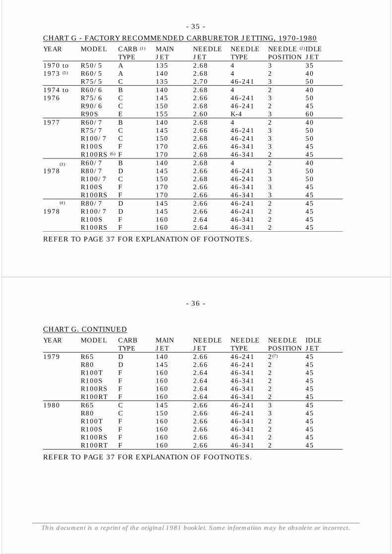
- 35 -CHART G - FACTORY RECOMMENDED CARBURETOR JETTING, 1970-1980YEAR MODEL CARB (1) MAIN NEEDLE NEEDLE NEEDLE (2) IDLE
TYPE JET JET TYPE POSITION JET1970 to R50/5 A 135 2.68 4 3 351973 (5) R60/5 A 140 2.68 4 2 40
R75/5 C 135 2.70 46-241 3 501974 to R60/6 B 140 2.68 4 2 401976 R75/6 C 145 2.66 46-241 3 50
R90/6 C 150 2.68 46-241 2 45R90S E 155 2.60 K-4 3 60
1977 R60/7 B 140 2.68 4 2 40R75/7 C 145 2.66 46-241 3 50R100/7 C 150 2.68 46-241 3 50R100S F 170 2.66 46-341 3 45R100RS (6) F 170 2.68 46-341 2 45
(3) R60/7 B 140 2.68 4 2 401978 R80/7 D 145 2.66 46-241 3 50
R100/7 C 150 2.68 46-241 3 50R100S F 170 2.66 46-341 3 45R100RS F 170 2.66 46-341 3 45
(4) R80/7 D 145 2.66 46-241 2 451978 R100/7 D 145 2.66 46-241 2 45
R100S F 160 2.64 46-341 2 45R100RS F 160 2.64 46-341 2 45
REFER TO PAGE 37 FOR EXPLANATION OF FOOTNOTES.
- 36 -
This document is a reprint of the original 1981 booklet. Some information may be obsolete or incorrect.
CHART G. CONTINUEDYEAR MODEL CARB MAIN NEEDLE NEEDLE NEEDLE IDLE
TYPE JET JET TYPE POSITION JET1979 R65 D 140 2.66 46-241 2(7) 45
R80 D 145 2.66 46-241 2 45R100T F 160 2.64 46-341 2 45R100S F 160 2.64 46-341 2 45R100RS F 160 2.64 46-341 2 45R100RT F 160 2.64 46-341 2 45
1980 R65 C 145 2.66 46-241 3 45R80 C 150 2.66 46-241 3 45R100T F 160 2.66 46-341 2 45R100S F 160 2.66 46-341 2 45R100RS F 160 2.66 46-341 2 45R100RT F 160 2.66 46-341 2 45
REFER TO PAGE 37 FOR EXPLANATION OF FOOTNOTES.
- 37 -
FOOTNOTES - CHART G
1 CARBURETOR TYPESA - Bing 26mm slide-throttle with acc. pump in needle jet housing and push-
button tickler for fuel enrichment.B - Bing 26mm slide-throttle type with acc. pump in needle jet housing and
cable-operated enrichment device.C - Bing 32mm Constant Velocity type with Slide Piston Guide Sleeve in dome.D - Bing 32mm Constant Velocity type with flat top (no sleeve)E - Dell'orto 38mm slide-throttle type with acc. pumpF - Bing 40mm Constant Velocity type
2 Count needle notches down from top to determine position. Measure length ofneedle projecting from slide to check setting.
3 1978 models produced prior to January 1, 1978 were not subject to E.P.A.emissions regulations.
4 1978 models produced after January 1, 1978 subject to E.P.A. Control.
5 Early production R50/5 models (up to engine # 2900441) were jetted as follows;Main Jet-145. Needle Jet-2.68. Needle type-4. Needle Position-2. Idle Jet-35.
6 This line applies only to 1977 R100RS models fitted with 40mm exhaust system.Models with 38mm exhaust system are jetted identically to 1977 R100S model.
7 R65 models were changed to needle position 3 to cure lean running.
- 38 -
This document is a reprint of the original 1981 booklet. Some information may be obsolete or incorrect.
H.) WIRING DIAGRAM FOR THE DUAL PLUG IGNITION SYSTEM(COURTESY OF WALUS ENGINEERING, BEECHER, ILLINOIS)
- 39 -
MODIFICATION TO THE CONTACT POINTS BREAKER PLATE AND POINTS FORTIMING ADJUSTMENT (SEE PAGE 18)
- 40 -
This document is a reprint of the original 1981 booklet. Some information may be obsolete or incorrect.
RECORD ALL SETTINGS HEREORIGINAL SETTINGS FIRST CONVERSION FINAL
CARBURETOR JETTING
MAIN JET:
NEEDLE JET:
NEEDLE POSITION:
IGNITION TIMING:
REF. NOTCH -
FUEL MILEAGE:
TANK # 1
TANK # 2
TANK # 3