owners handbook (full may 06) - boat service haarlem · owners handbook marine ... ltd distributors...
TRANSCRIPT
owners handbook
Marine Transmissions
PRM80
PRM120
PRM150
PRM260
PRM500
PRM750
PRM1000
PRM1500
PRM1750

WARRANTY REGISTRATION FORM
Gearbox Model Engine Make
Gearbox Serial Number Engine Model
Date of Commissioning Type of Application (please tick)
Owners/Operators Name Pleasure Commercial
& Address
Type of Vessel (please tick)
Canal Craft Sailing Fishing
Country Other, please specify:
Telephone No.
Signature Date
Failure to return this form may invalidate the warranty

Newage Transmissions LtdAldermans Green Industrial EstateBarlow RoadCOVENTRYCV2 2LDENGLAND
PLEASEAFFIX
POSTAGESTAMPHERE

Contents Page
Warranty Statement & General Information 2
Installation Advice 3
Nominal Power Ratings 4
Service Classification 5
Oil Type 5
Oil Capacities and Pressures 6
Oil Level Checking 6
Oil Pump Mounting 7
Operation 8
Emergency Operation (not PRM80/120) 9
Routine Maintenance 10
Optional Equipment 11
Fault Finding Chart 12-13
Overseas Distributor Network 14-16
UK Distributor Network 16
Warranty Registration Card Inside front cover
Maintenance Record Inside rear cover
WARNING: THIS SYMBOL WARNS OF POSSIBLE PERSONAL INJURY.
CAUTION: THIS SYMBOL WARNS OF ANY POSSIBLE DAMAGE TO TRANSMISSION.
Newage Transmissions operate a policy of product improvement and therefore reserve the right to change specifications without prior notification.Whilst every effort is made to ensure complete accuracy of the information in this manual no liabilities for inaccuracies or the consequences thereof can be accepted bythe manufacturer or the distributor/dealer who supplied the manual.
1
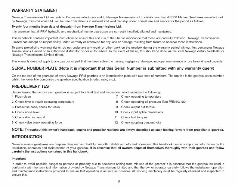
WARRANTY STATEMENT
Newage Transmissions Ltd warrants to Engine manufacturers and to Newage Transmissions Ltd distributors that all PRM Marine Gearboxes manufacturedby Newage Transmissions Ltd will be free from defects in material and workmanship under normal use and service for the period as follows,
Twenty four months from date of despatch from Newage Transmissions Ltd.
It is essential that all PRM hydraulic and mechanical marine gearboxes are correctly installed, aligned and maintained.
This handbook contains important instructions to ensure this and it is of the utmost importance that these are carefully followed. Newage TransmissionsLimited can accept no responsibility under warranty or otherwise for any loss or damage resulting from failure to observe these instructions.
To avoid prejudicing warranty rights, do not undertake any repair or other work on the gearbox during the warranty period without first contacting NewageTransmissions Limited or an authorised distributor or dealer for advice. In the event of failure, this should be done via the local Newage distributor/dealer orNewage Transmissions Limited direct.
This warranty does not apply to any gearbox or part that has been subject to misuse, negligence, damage, improper maintenance or use beyond rated capacity.
SERIAL NUMBER PLATE (Note it is important that this Serial Number is submitted with any warranty query)
On the top half of the gearcase of every Newage PRM gearbox is an identification plate with two lines of numbers. The top line is the gearbox serial number,whilst the lower line comprises the gearbox specification (model, ratio, etc.).
PRE-DELIVERY TESTBefore leaving the factory each gearbox is subject to a final test and inspection, which includes the following:1 Flush clean 7 Check operating temperature
2 Check time to reach operating temperature 8 Check operating oil pressure (Not PRM80/120)
3 Pressurise case, check for leaks 9 Check output nut torque
4 Check noise level 10 Check input spline dimensions
5 Check drag in neutral 11 Check bolt torques
6 Check valve block operating force 12 Check coupling concentricity
NOTE: Throughout this owner’s handbook, engine and propeller rotations are always described as seen looking forward from propeller to gearbox.
INTRODUCTION
Newage marine gearboxes are purpose designed and built for smooth, reliable and efficient operation. This handbook contains important information on theinstallation, operation and maintenance of your gearbox. It is essential that all owners acquaint themselves thoroughly with their gearbox and followcarefully the instructions contained in this handbook.
Important
In order to avoid possible danger to persons or property due to accidents arising from mis-use of the gearbox it is essential that the gearbox be used inconformity with the technical information provided by Newage Transmissions Limited and that the owner operator carefully follows the installation, operationand maintenance instructions provided to ensure that operation is as safe as possible. All working machinery must be regularly checked and inspected toensure this.
2

3
INSTALLATION
Engine/Gearbox Drive
Drive is transmitted to the gearbox via a flexible input coupling mounted on the engine flywheel, into the centre of which the gearbox input shaft locates.It is most vital that engine, gearbox and coupling are correctly aligned; if not, vibration, transmission noise and even failure may result. For completealignment instructions refer to the gearbox workshop manual.
Oil Cooler
All Newage gearboxes (except PRM80/120) must be fitted with an oil cooler to maintain correct working temperatures. Two 3/8 in. BSP (1/4 in. BSP onPRM150, 1/2 in. BSP on PRM1500) connections are provided on the valve block to allow a suitable cooler to be fitted; these are blanked off with ”Redcap”plugs for delivery from the factory. The gearbox oil cooler is usually mounted on the gearbox adaptor flange or the bulkhead of the boat and then connectedinto the engine cooling system. Full instructions on cooler installation are provided in the workshop manual. See caution note reference cooler pressures page 7.
Propeller Shaft Alignment
Correct alignment of the propeller shaft coupling flange and the gearbox output flange is essential, since misalignment can cause excessive vibration and stress, leading to damage and possible oil seal and bearing failure.Alignment should only be carried out with the boat afloat, the maximum permissible misalignment being 0.05mm; see workshop manual forinstructions.
Installation Angle
The transmission should normally be installed so that the maximum fore and aft angle relative to the waterline does not exceed 17° (15° on PRM80/120/150)with the vessel at rest. If installation angles greater than this are required, please consult Newage Transmissions Limited for advice.
Twin Installations (Not PRM80/120)
For efficient operation, it is usually considered preferable for the starboard (right hand) propeller to rotate clockwise and the port (left hand) propeller to rotate anti-clockwise.
Remote Control Operating System
It is strongly recommended that Newage PRM gearboxes are used with a remote control operating system, which should be connected strictly inaccordance with the manufacturer’s recommendations. Care must be taken to ensure that the cable moves the gearbox operating lever approximately2mm short of its forward or backward travel, to prevent the lever being brought ‘hard-up’ against its end stop with every gear shift. This does not apply toPRM80/120 which must be adjusted against the stop in both directions. Failure to correctly adjust the shift lever may result in premature wear to the drivetrain.Newage PRM gearboxes are provided with a positive neutral position, which greatly assists in setting up the remote control operating system.
4
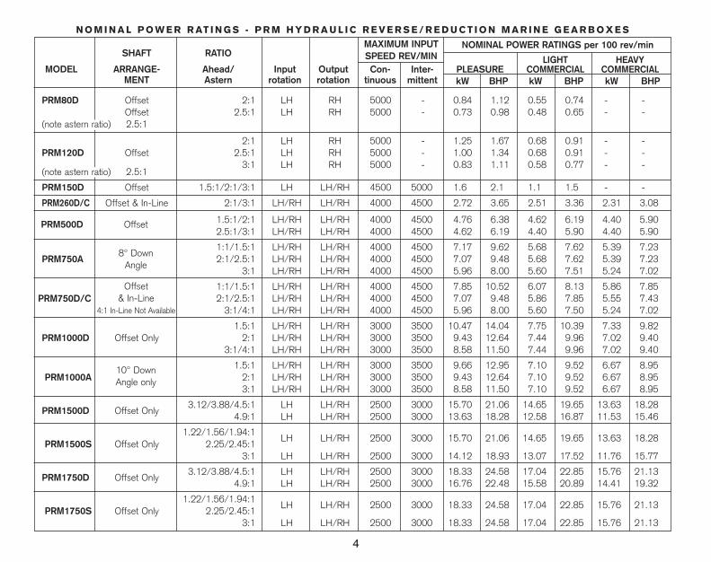
NOMINAL POWER RATINGS per 100 rev/minMAXIMUM INPUTSPEED REV/MIN
Inter-mittent
Con-tinuous
LIGHT HEAVYPLEASURE COMMERCIAL COMMERCIALkW BHP kW BHP kW BHP
Offset& In-Line
4:1 In-Line Not Available
N O M I N A L P O W E R R AT I N G S - P R M H Y D R A U L I C R E V E R S E / R E D U C T I O N M A R I N E G E A R B O X E S
SHAFT RATIO
MODEL ARRANGE- Ahead/ Input OutputMENT Astern rotation rotation
PRM80D Offset 2:1 LH RH 5000 - 0.84 1.12 0.55 0.74 - -Offset 2.5:1 LH RH 5000 - 0.73 0.98 0.48 0.65 - -
(note astern ratio) 2.5:1
2:1 LH RH 5000 - 1.25 1.67 0.68 0.91 - -PRM120D Offset 2.5:1 LH RH 5000 - 1.00 1.34 0.68 0.91 - -
3:1 LH RH 5000 - 0.83 1.11 0.58 0.77 - -(note astern ratio) 2.5:1
PRM150D Offset 1.5:1/2:1/3:1 LH LH/RH 4500 5000 1.6 2.1 1.1 1.5 - -
PRM260D/C Offset & In-Line 2:1/3:1 LH/RH LH/RH 4000 4500 2.72 3.65 2.51 3.36 2.31 3.08
1.5:1/2:1 LH/RH LH/RH 4000 4500 4.76 6.38 4.62 6.19 4.40 5.902.5:1/3:1 LH/RH LH/RH 4000 4500 4.62 6.19 4.40 5.90 4.40 5.90
1:1/1.5:1 LH/RH LH/RH 4000 4500 7.17 9.62 5.68 7.62 5.39 7.23PRM750A 2:1/2.5:1 LH/RH LH/RH 4000 4500 7.07 9.48 5.68 7.62 5.39 7.23
3:1 LH/RH LH/RH 4000 4500 5.96 8.00 5.60 7.51 5.24 7.02
1:1/1.5:1 LH/RH LH/RH 4000 4500 7.85 10.52 6.07 8.13 5.86 7.85PRM750D/C 2:1/2.5:1 LH/RH LH/RH 4000 4500 7.07 9.48 5.86 7.85 5.55 7.43
3:1/4:1 LH/RH LH/RH 4000 4500 5.96 8.00 5.60 7.50 5.24 7.02
1.5:1 LH/RH LH/RH 3000 3500 10.47 14.04 7.75 10.39 7.33 9.82PRM1000D Offset Only 2:1 LH/RH LH/RH 3000 3500 9.43 12.64 7.44 9.96 7.02 9.40
3:1/4:1 LH/RH LH/RH 3000 3500 8.58 11.50 7.44 9.96 7.02 9.40
1.5:1 LH/RH LH/RH 3000 3500 9.66 12.95 7.10 9.52 6.67 8.95PRM1000A 2:1 LH/RH LH/RH 3000 3500 9.43 12.64 7.10 9.52 6.67 8.95
3:1 LH/RH LH/RH 3000 3500 8.58 11.50 7.10 9.52 6.67 8.95
3.12/3.88/4.5:1 LH LH/RH 2500 3000 15.70 21.06 14.65 19.65 13.63 18.28PRM1500D Offset Only
4.9:1 LH LH/RH 2500 3000 13.63 18.28 12.58 16.87 11.53 15.46
1.22/1.56/1.94:1LH LH/RH 2500 3000 15.70 21.06 14.65 19.65 13.63 18.28
PRM1500S Offset Only 2.25/2.45:13:1 LH LH/RH 2500 3000 14.12 18.93 13.07 17.52 11.76 15.77
3.12/3.88/4.5:1 LH LH/RH 2500 3000 18.33 24.58 17.04 22.85 15.76 21.13PRM1750D Offset Only
4.9:1 LH LH/RH 2500 3000 16.76 22.48 15.58 20.89 14.41 19.32
1.22/1.56/1.94:1LH LH/RH 2500 3000 18.33 24.58 17.04 22.85 15.76 21.13
PRM1750S Offset Only 2.25/2.45:13:1 LH LH/RH 2500 3000 18.33 24.58 17.04 22.85 15.76 21.13
PRM500D Offset
8° DownAngle
10° DownAngle only

Note: These powers are expressed in BHP and KW per 100 rev/min engine operating speed and are measured at the engine flywheel. Ratings havebeen established to ensure the long and trouble free life of the gearbox which should not therefore, be used at powers in excess of those shown.Newage Transmissions Limited accepts no liability, whether under warranty or otherwise, in respect of transmissions which have been used at ratings higher than those listed above.
5
SERVICE CLASSIFICATION DEFINITIONS
PLEASURE: limited to planing hull pleasure craft with a maximum of 500 hours operating time per year, of which not more than 5% should be at fullengine throttle, with the balance of usage at 90% or less of full throttle. The use of PRM marine gearboxes according to this classification in any commercialboat, or in sport-fishing charter boats or long-range pleasure cruisers, is not approved.
LIGHT COMMERCIAL: planing or semi-displacement craft used in pleasure or commercial application may qualify for light commercial rating if annualusage is less than1500 hours and full throttle operation is limited, with most operating time at partial throttle.
HEAVY COMMERCIAL: all displacement and semi-displacement craft used for commercial applications should be classed as heavy commercial duty.In this type of vessel (such as trawlers, purse seiners, lobster and crab boats, tugs, ferries, offshore supply boats etc.) the gearbox is expected to work atfull governed engine speed. The power setting of the engine must be known and must be within the permitted heavy commercial rating of the gearbox.
IMPORTANT NOTE
1 It is essential that the engine, transmission model, reduction ratio and propeller size are correctly matched so that the engine can attain its rated speed appropriate to the relevant service classification without labouring.
2 It is also necessary to ensure the torsional compatibility of the complete propulsion system from engine through to propeller, since disregarding this may result in gear noise, particularly at low speed operation and may even result in damage to the engine as well as to transmission components.
Newage Transmissions Limited will provide all possible information and assistance to help find solutions to potential torsional problems, but it is theultimate responsibility of the person assembling the drive and driven equipment to ensure that they are torsionally compatible.
It is essential that only good quality engine oil, supplied by a recognised and well known manufacturer, is used in Newage PRM Marine Transmissions.Do not mix different brands, types or grades of oil.
Failure to comply with the above oil types or to seek advice from Newage Transmissions Ltd. for approval for any type of oil not listed may result in forfeitureof warranty cover since no claims under warranty will be entertained if oil of the wrong type is used.
TEMP.Below Zero
0°C to 30°C
Above 30°C 10W30 or 40W. Engine Oil.
10W30 or 15W40. Engine Oil.
10W30 or 20W. Engine Oil.
TYPE OF OIL
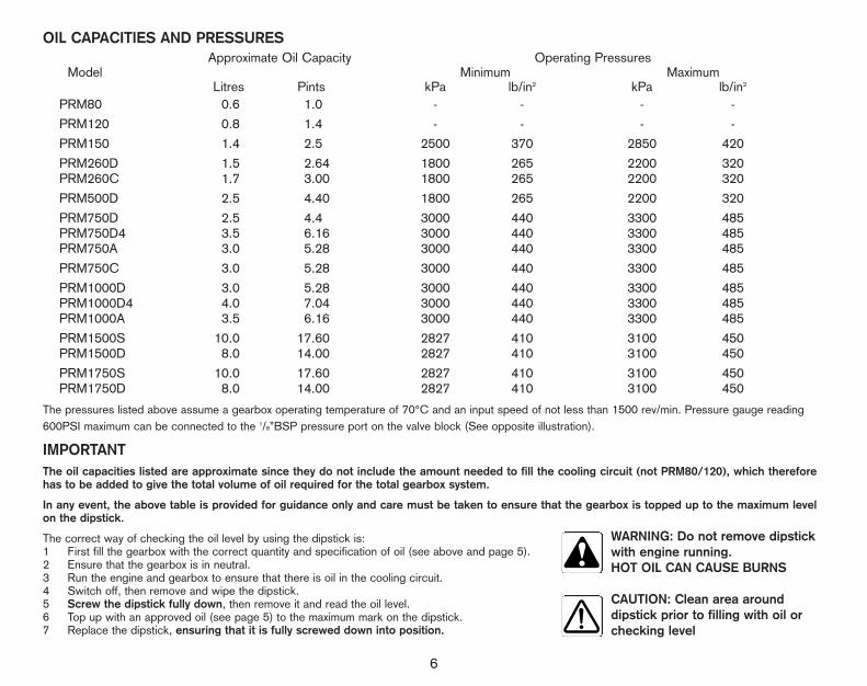
OIL CAPACITIES AND PRESSURES
The pressures listed above assume a gearbox operating temperature of 70°C and an input speed of not less than 1500 rev/min. Pressure gauge reading600PSI maximum can be connected to the 1/8”BSP pressure port on the valve block (See opposite illustration).
IMPORTANTThe oil capacities listed are approximate since they do not include the amount needed to fill the cooling circuit (not PRM80/120), which thereforehas to be added to give the total volume of oil required for the total gearbox system.
In any event, the above table is provided for guidance only and care must be taken to ensure that the gearbox is topped up to the maximum levelon the dipstick.
The correct way of checking the oil level by using the dipstick is:1 First fill the gearbox with the correct quantity and specification of oil (see above and page 5).2 Ensure that the gearbox is in neutral. 3 Run the engine and gearbox to ensure that there is oil in the cooling circuit.4 Switch off, then remove and wipe the dipstick.5 Screw the dipstick fully down, then remove it and read the oil level.6 Top up with an approved oil (see page 5) to the maximum mark on the dipstick.7 Replace the dipstick, ensuring that it is fully screwed down into position.
Approximate Oil Capacity Operating PressuresModel Minimum Maximum
Litres Pints kPa lb/in2 kPa lb/in2
PRM80 0.6 1.0 - - - -
PRM120 0.8 1.4 - - - -
PRM150 1.4 2.5 2500 370 2850 420
PRM260D 1.5 2.64 1800 265 2200 320PRM260C 1.7 3.00 1800 265 2200 320
PRM500D 2.5 4.40 1800 265 2200 320
PRM750D 2.5 4.4 3000 440 3300 485PRM750D4 3.5 6.16 3000 440 3300 485PRM750A 3.0 5.28 3000 440 3300 485
PRM750C 3.0 5.28 3000 440 3300 485
PRM1000D 3.0 5.28 3000 440 3300 485PRM1000D4 4.0 7.04 3000 440 3300 485PRM1000A 3.5 6.16 3000 440 3300 485
PRM1500S 10.0 17.60 2827 410 3100 450PRM1500D 8.0 14.00 2827 410 3100 450
PRM1750S 10.0 17.60 2827 410 3100 450PRM1750D 8.0 14.00 2827 410 3100 450
WARNING: Do not remove dipstickwith engine running.HOT OIL CAN CAUSE BURNS
CAUTION: Clean area around dipstick prior to filling with oil orchecking level
6

7
Pressure GaugeConnection
Note: using the gearbox with insufficient oil is likely to lead to low oil pressure, unsatisfactory operation, overheating and eventual failure. Equally, filling the gearboxwith too much oil may cause overheating and oil leaks; it is the owner/operators responsibility, therefore, to ensure that the oil level is correct at all times.
Dipstick LocationPRM80 1/2 in. A/F hex plug, front of case, R/H side; PRM120 18mm A/F hex plug, rear of case, R/H side; PRM150 18mm A/F hex plug, rear of case, L/H side;PRM260/500/750 18mm A/F hex plug, front of case, R/H side; PRM1000 18mm A/F hex plug, front of case, L/H side; PRM1500/1750 18mm A/F hexplug, R/H side mounting pad.
If the operating pressure is below the minimum value listed for your specific gearbox model, corrective action must be taken (see fault-finding chart)or gearbox damage may result. (Not applicable to PRM80/120.)If operating pressure is higher than the maximum listed, (other than for very short periods after start-up when the oil is still cold), qualified assistancemust be sought to correct the condition. (Not applicable to PRM80/120.)
It is important to ensure that any oil cooler used is capable of withstanding lubrication pressures in the order of 2040 kpm (300lb/in2). This may be seen on initial start-up from cold at maximum engine speed.
GENERAL
Input RotationIn their standard form, Newage PRM marine gearboxes are built for use with left hand (anti-clockwise) rotating engines, at the ratings listed on page 4. Themajority can, however, easily be adapted to accept right-hand (clockwise) rotating engines, simply by turning the oil pump through 180°. (Note: this does notapply to the PRM80/120/150/1500/1750 gearboxes, which must be used with left hand rotating engines only.)
The mounting positions of the oil pump are as follows:-
Note: Engine rotation is described as seen looking on the flywheel from behind the engine.
OIL PUMP MOUNTING(Not applicable to PRM80/120/150/1500 & 1750)
anti-clockwise engines(or clockwise on angle drive and in-line gearboxes)
clockwise engines(or anti-clockwise on angle drive and in-line gearboxes)
8
Output Rotation (does not apply to PRM80/120)
Because Newage PRM gearboxes have identical clutches, gears and bearings on both input shaft and layshaft, either a L.H. or R.H. propeller can be usedat their full speed and horse power ratings, irrespective of input rotation (see rating chart). (PRM150/1500/1750: L.H. input rotation only.)
On all offset gearboxes (except PRM150) used with the more common left hand (anti-clockwise) rotating engines, moving the gearbox operating lever backprovides right hand propeller rotation and moving it forward provides left hand propeller rotation.
If the gearbox is used with the less common right hand (clockwise) rotating engines, the operation is reversed:- moving the gearbox operating lever backprovides left hand propeller rotation and moving it forward gives right hand propeller rotation. On angle drive (PRM750A, PRM1000A) and in-line (PRM260C, PRM750C) gearboxes, the movement of the operating lever is the reverse of that described above.
On PRM150 only moving the gearbox operating lever to port provides right hand propeller rotation and moving it to starboard provides left hand propellerrotation.
IMPORTANT RIGHT HAND PROPELLER REQUIRED FOR PRM80/120
NoteEngine and propeller rotations are described as seen looking forward from propeller to gearbox. In order to achieve the best possible gear shifting, it isrecommended that a single lever control system (i.e. connected to the engine throttle as well as the gearbox) should be used.
OPERATIONFirst Time Usage
Before starting the engine remove the dipstick, fill the gearbox with one of the recommended lubricants (see table on page 5) to the maximum mark on thedipstick, then replace the dipstick by screwing it fully down for correct level.
Ensure that the gearbox is in neutral (we recommend that the optional neutral safety start switch (not available on PRM80/120) be wired into the starter circuit to avoid uncontrolled boat movement on start-up), then start the engine and run for a few minutes to allow the oil to circulate through the cooling circuit. Stop the engine, let the oil settle, then re-check the level and ‘top up’ to the maximum mark on the dipstick (see page 5).
Operating Temperature
Normal operating temperature should be between 50°C - 80°C with a maximum of 90°C (120°C for PRM80/120) permissible for very short periods only. If the gearbox consistently runs at temperatures above 80°C, carry out the checks listed in the fault-finding chart; if no fault is found, fit a larger capacity cooler.
Gear Shifting (Except PRM80/120)
Newage PRM Hydraulic marine gearboxes have been designed and tested to ensure rapid shifts from ahead to astern and vice versa at full horsepower ratings and speeds if necessary. However, since full-power shifts do place abnormal, even if short lived, loads on the gearbox and if usedindiscriminately will reduce its operating life, they should be reserved for emergency use only.
Gear Shifting PRM80/120 only.Engine must be at idle before changing direction. Pause in neutral when selecting ahead or astern. The PRM80/120 can be used with remote control operating systems which must be of the single lever type of remote control, i.e. Morse MT3 or SL3 which controls both the engine throttleand gear selection.
Trailing (Free-wheeling) the Propeller
The bearings used in Newage gearboxes have been carefully selected to ensure that prolonged trailing (free-wheeling) of the propeller will not harm thetransmission. This allows the propeller to turn freely with the engine shut down, making the gearbox particularly well suited for use in auxiliary sailboats, motor sailers, or multi-engine installations where the boat may be operated with one or more engines shut down.
9
Emergency Operation (Not applicable to PRM80/120)
Included as standard in every Newage PRM Hydraulic marine gearbox is a “get-you-home” device which, in the unlikely event of hydraulic failure, enablesthe gearbox to be locked in ‘ahead‘ allowing the boat to be brought to safety.
To operate, first switch off the engine, disconnect the operating cable and ensure that the gearbox operating lever is in the neutral position,then proceed as follows:
a PRM1501 Remove the 9 hexagonal bolts securing the rear manifold to the gearcase and taking care not to lose the small socket wrench located inside it, take off
the manifold complete with oil pump.
2 Rotate the input shaft until two socket screws in the clutch align with the two holes in the rear of the gearcase.
3 Insert the socket wrench through the two holes and tighten each screw in turn; this locks up the clutch plates, providing drive for a right-hand rotatingpropeller. (Note: left-hand rotation cannot be provided).
4 Refit the rear manifold and tighten the bolts to a torque of 30Nm .
5 Ensure that sufficient oil remains in the gearbox to avoid further damage.
b PRM2601 Remove the top cover (located alongside the valve block).
2 Select the shaft which provides the appropriate propeller rotation (see note ‘a’ on page 10) and rotate until one of the grooves on the outer edgesof the clutch end plate is uppermost.
3 Take one of the top cover securing screws and screw it tightly into the threaded hole in the clutch plate directly beneath the groove: this clamps the clutch and provides drive.
4 Check that the dipstick does not foul the head of the screw now fitted in the clutch: if it does, remove the dipstick and plug the hole with a clean cloth.
5 Ensure that sufficient oil remains in the gearbox to avoid further damage and refit the top cover, tightening the bolts to a torque of 28Nm .
c PRM500 and PRM7501 Remove the top cover (located alongside the valve block).
2 Select the shaft to provide the required propeller rotation (see note ‘a’ on page 10) and rotate until the spring clip, which holds the two clamping screws in position, is accessible.
3 Remove the spring clip and tighten the two screws: this locks up the clutch pack and provides the drive.
4 Check that the dipstick does not foul the head of either clamping screw: if it does, remove the dipstick and plug the hole with a clean cloth.
5 Ensure that sufficient oil remains in the gearbox to avoid further damage and refit the top cover, tightening the bolts to a torque of 28Nm .
d PRM1000
1 Remove the top cover (located alongside the valve block): the hexagonal key for operating the emergency device is held in a clip on the underside of this cover.
2 Select the shaft to provide the required propeller rotation (see note ’a’ below).
3 Locate the clutch end plate: this has three tapped holes, angled to provide access. Rotate the shaft until one of the holes is uppermost.
4 Insert the hexagonal key and screw the grub screw as tight as possible, rotating the clutch gear to ensure the screw locates in between the spline teeth.
5 Rotate the shaft and similarly tighten the other two grub screws.
6 Ensure that sufficient oil remains in the gearbox to avoid further damage and refit the top cover, tightening the bolts to a torque of 28Nm .

10
e PRM1500/1750
1 Remove the oil pump, held on by 6 hexagonal bolts.2 Remove shimming and bearing cup.3 Rotate the input shaft by using the pump slot to expose 4 socket headed grub screws. These need to be tightened with a 4mm hexagon key to engage the clutch.4 Repeat above operation by removing the cover, if appropriate clutch is used for ahead. This is located next to the oil pump.5 Replace bearing cup and shimming.6 Re-seal the oil pump back into place and fix on with the six bolts.7 Ensure that sufficient oil remains in the gearbox to avoid further damage.
The engine can now be run, but to minimise the possibility of further damage being caused to the gearbox, engine speed should be limited to 1/3rd full throttle.
IMPORTANT NOTESa Assuming an anti-clockwise engine, the shaft to select is:
- left hand propeller: left hand shaft (PRM260D, 500D, 750D, 1000D, 1500S/D, 1750S/D)right hand shaft (PRM260C, 750A, 750C, 1000A)
- right hand propeller: right hand shaft (PRM260D, 500D, 750D, 1000D, 1500S/D, 1750S/D)left hand shaft (PRM260C, 750A, 750C, 1000A)
(all rotations are described as seen looking forward from the propeller to the gearbox).
(only right hand propeller rotation can be provided by the PRM150 emergency device).
b When emergency drive is engaged, neither astern or neutral can be used and there is thus no means of stopping the boat using the gearbox; consequently great care must be taken when manoeuvring the boat, particularly during docking.
c After emergency drive has been used, qualified assistance must be sought to check the transmission thoroughly before it is used again.
d Never use the top cover for topping up the oil.
ROUTINE MAINTENANCEIt is recommended that all Newage gearboxes be run for 15minutes before the oil is drained and replaced.
After the first 25 hours runningRun the engine until the oil reaches a minimum temperature of 50°C, then switch off, drain the oil from the gearbox and cooling system and re-fill with one of therecommended lubricants. Operate the engine and gearbox, allowing the oil to circulate, then stop the engine and let the oil settle. Re-check the oil level by screwingthe dipstick down fully and top up if necessary to the maximum mark on the dipstick.Note: Drain plug located rear right hand side on PRM1500/1750, 1000, 750 and 150, front on 500 and 260 and in the centre of the main case of PRM80/120.
WARNING: Hot oil burns
Daily
Check the oil level and check visually for oil leaks, especially around the output shaft oil seal and at gasket sealing surfaces.
Annually
Check oil cooler hoses and connections and correct/replace as necessary. Check propeller shaft alignment and correct if necessary. Ensure that the remotecontrol operating linkage is adjusted to give the correct travel on the gearbox operating lever (see page 3). Check that all fasteners are tightened to the correcttorque (see workshop manual for this information).
Oil changes
Gearbox oil should routinely be changed annually or at intervals corresponding with engine oil changes, whichever occurs first. However, if the oil shouldbecome contaminated by water, or if the gearbox suffers major mechanical damage, the gearbox, oil cooler and hoses must be thoroughly flushed out andthe gearbox re-filled with fresh oil to the correct specification.
WARNING: Hot oil burns
OPTIONAL EQUIPMENTNeutral Safety Switch (Not available for PRM80/120)
This switch ensures the engine cannot be started unless the gearbox is in neutral; Newage Transmissions Limited strongly recommends that it should be fitted in all installations. The device is standard supply on the PRM1000.
Power Take Off - PRM500/750/1000/1500/1750
The power take off mounts directly to the rear face of the gearbox and is available factory fitted or as an assembly for retro-fitting on existing gearbox installations.
It is designed for use with hydraulic pumps to SAE J744C series “B” (and series “C” for PRM1500/1750 only) specification and is a very compact,economical and effective method of powering hydraulic equipment on vessels where the provision of an auxiliary drive from the main engine may be difficultor expensive.
Whilst gear, vane or piston hydraulic pumps can be used with these units, they must not be fitted with any adaption for driving an outrigger pulleysince the mounting provided is not designed to handle the side loads which this would entail.
The clutched PTO unit available on the PRM1000 provides pump rotation in the same direction as the engine, whereas the clutched PTO for the PRM1500/1750and the direct drive PTO offered for the PRM500 and PRM750 provides rotation opposite to the engine.
IMPORTANT NOTE - PRM1000/1500/1750 ONLY - PTO Retrofit. A soft shift valve is fitted as standard. When retro-fitting a PTO this valveMUST be changed using the replacement valve block supplied with the PTO kit.
All hydraulic circuits driven by Newage PTOs must be designed, installed and maintained in accordance with the hydraulic equipmentmanufacturer’s recommendations and be properly safeguarded against overloading.
Angle Drives - PRM750A/1000A
The angle drive assembly mounts on the front of the gearbox and provides a down angle on the output shaft of 8° on the PRM750, and of 10° on thePRM1000. It also reduces the centreline distance between the engine crankshaft and the gearbox output shaft.
Note: If an angle drive is retro-fitted, the gearbox output rotation will be reversed, it will therefore be necessary to reverse the control lever movements to give the correct output rotation for ‘ahead’ or ‘astern’ (see page 8). The oil capacity also increases (see chart, page 6) and a replacement dipstick will haveto be fitted. (See reference to pump position below).
In-line- PRM260C/750C
A factory fitted ‘step-up’ gearbox fitted to the main gearcase brings the output shaft on to the same centreline as the input shaft and reproduces the inputshaft length and spline, the adaptor flange and the mounting pads used on certain competitors in-line gearboxes. For oil pump mounting positions, operatinglever movements and output rotations (see pages 7 and 8).
Trolling Valve - PRM260,500,750,1000,1500,1750
A separate instruction leaflet is issued with each trolling valve.
11

12
FAULT FINDING CHART
Symptom Cause Reason Remedy
No drive ahead or astern No oil pressure* Damaged oil pump* Replace oil pump*Broken input coupling Replace couplingOil leaks Check for evidence and rectifyInsufficient oil Check level, top up as necessary
Propeller speed does not increase Low oil pressure to both clutches* Damaged oil pump* Replace oil pump*with engine speed,ahead and Remote control cable or linkage Remove cable and operate leverastern not allowing F-N-R lever to move by hand to check movement.
correct distance Adjust cable if necessary
Pressure relief valve spring defective* Remove valve block and replace spring*
Propeller speed does not increase Low oil pressure to one clutch* Piston rings or feeder worn* Remove appropriate clutch shaftwith engine speed in one direction and replace worn feeder or pistononly rings*
Blocked oil strainer* Remove, clean and replace if necessary*
Damaged ’O’ ring in hydraulic Check ‘O’ rings in feeder connectorscircuit* and piston; replace if necessary*
Blocked hydraulic passage in valve Remove valve block, examine and clean*block*
Damaged clutch plates Remove and examine clutch/clutch coneor clutch cones (PRM80/120) on appropriate shaft and replace if
necessary
Excessive noise from gearbox at Engine idle speed set too low Faulty adjustment Increase idling speedlow speeds
Torsional vibration Torsional incompatibility of If not cured by increasing engine idlingelements in driveline speed, refer to engine supplier
Excessive noise throughout Defective input coupling Input coupling worn or damaged Remove, examine and replace if operating range necessary
Propeller shaft misalignment Hull flexing or faulty installation Check the alignment of the propellershaft coupling; if necessary rectify by adjusting the shims under the engine mounts or the engine mounts themselves
*does not apply to PRM80/120

13
Symptom Cause Reason Remedy
Excessive noise throughout Propeller out of balance Propeller damaged or badly machined Remove the propeller and check thatoperating range the pitch, weight, diameter and
balance of all the blades are equal andrectify if necessary
Engine/gearbox misalignment Faulty installation Remove the transmission and checkthat the flywheel face is flat and that the flexible input coupling is aligned correctly
Defective bearing Bearing worn or damaged Isolate defective bearing, remove and replace
Excessive oil temperature Fault in cooling system* Defective oil cooler* Replace oil cooler*
Oil cooler too small* Fit larger capacity cooler*
Defective pressure relief valve* Remove and examine relief valve*and replace if necessary
System blocked* Check and flush out oil cooler and *hoses
Oil pipes too small* Fit larger diameter hoses*
Power too high Incorrect engine rating Re-assess engine power
Oil level needs constant Oil leaks Defective oil seal, gasket or Clean the outside of the gearcase,topping-up ’O’ ring particularly around the ends of shafts
including the output shaft. Run theengine and inspect the gearbox for leaks. Replace seals as required
Defective oil cooler or hoses* Check for traces of water in the gearbox oil or oil in the cooling water system. Replace cooler or hoses as necessary
Escape of high pressure from Defective breather causing leaks Contact distributor or factory for gearbox when dipstick is removed past oil seals advice
Difficulty in moving single lever control Control lever on valve block too stiff Defective valve or detent spring Contact distributor or factory for advice
Faulty installation Remote control operating cable Check the installation and eliminate alltight bends in the cable
*does not apply to PRM80/120
IMPORTANT: The above operations should be carried out by suitably qualified personnel and strictly in accordance with the procedures detailed in the workshop manual. Before carrying out any service work always ensure that the engine is switched off and disconnect the operating cable from the gearbox.
14
AustraliaDrivetrain Marine Pty. Ltd.3/29 Armada PlaceBanyo Queensland 4014Tel +61 (0)7 3267 8800Fax +61 (0)7 3267 8811
Belgium & LuxembourgDintra Transmissies B.V.Keizerswoert 303881 LE PuttenHolland.Tel: +31 (0)3413 53712/57308Fax:+31 (0)3413 60046
Canada Jastram Technologies Ltd467 Mountain HwyNorth Vancouver B.C.V7J 2L3Tel: +1 (0) 604 986 0714Fax: +1 (0) 604 986 0334
Channel IslandsHerm Seaway MarineCastle EmplacementSt. Peter PortGuernsey.Tel: +44 (0)1481 726829Fax: +44 (0)1481 714011
ChileDistribuidora Perkins Chilena S.A.CAv. El Colorado 641Casilla 177 Correo 2QuilicuraSantiagoTel: +56 (0)2 6972929Fax: +56 (0)2 6717037
CyprusChar. Pilakoutas Ltd.P.O. Box 211687 Larnaca RoadNicosiaTel: 00 357 2 349812/349572Fax: 00 357 2 430294
DenmarkFred Rasmussen-Odense ApsOve Gjeddes Vej 23S220 Odense SØTel: +45 (0)65 560565Fax: +45 (0)65 560570
EgyptRamco for Engineering & Marine Supply148 Semouha Garden CityAlexandriaTel: +20 (0)3 4253155Fax: +20 (0)3 4253033
FinlandMepratuote Oy.Kaviokuja 820380 TurkuTel: 00 358 2 2750111Fax: 00 358 2 2750120
FranceI.D.S.Rue des Chantiers Crucy44100 NantesTel: +33 2 40 95 95 30Fax: +33 2 40 95 95 34
GermanyDintra Transmissies B.V.Keizerswoert 303881 LE PuttenHolland.Tel: +31 (0)3413 53712/57308Fax:+31 (0)3413 60046
GibraltarH. Sheppard & Co.Ltd.MarinaWaterportTel: +350 77183/75148Fax: +350 42535
GreeceLelis Diesel Marine15 Retsina StreetPiraeusTel: +30 (0)1 4127754Fax: +30 (0)1 4110166
Hong KongAutodiesel Trading Corp.G-4 Siu Wai Industrial CentreGround Floor29-33 Wing Hong StreetCheungshawan, KowloonTel: 00 852 2380-8301,2380-8302,Fax: 00 852 2397-3716
IcelandVelasalan EHFAnanaust 1101 ReykjavikTel: +354 5805300Fax: +354 5805301
IndiaVinayak Ventures155 Defence Officers ColonyEkkatuthangalChennai 600 032Tel: 00 91 44 2336679Fax: 00 91 44 2326325
IndonesiaMarunda Utama Engineering Pte. Ltd.29 Kaki Bukit Industrial EstateSingapore 416109Tel: +65 749 6888Fax: +65 749 2198
Irish RepublicT.M. MarineBunninassa Dromod P.O.Carrick-on-ShannonCo. LeitrimTel: +353 (0)7838041Fax: +353 (0)7838550
PRM MARINE TRANSMISSIONS - OVERSEAS DISTRIBUTOR NETWORK
15
ItalyIndemar s.p.aVia Guido Rossa 4216012 Busalla (Ge)Tel +39 010 964 1927Fax +39 010 964 1920
MaltaLeonard Bugeja29 Main StreetRabatTel: +356 2454120Fax: +356 2450302
MalaysiaTano Delph (Sea) Sdn.Bhd.81-M Medan Setia 1Bukit Damansara50490 Kuala LumpurTel:+60 (0)3 2556955Fax:+60 (0)3 2556955
NetherlandsDintra Transmissies B.V.Keizerswoert 303881 LE PuttenTel: +31 (0)3413 53712, 57308Fax: +31 (0)3413 60046
Netherlands AntillesWellman Auto Supplies N.V.P.O. Box 64CuracaoTel: 00 599 94614022/4614354/4614479Fax: 00 599 9 4618146
New ZealandDrivetrain Marine Pty. Ltd.3/29 Armada PlaceBanyo Queensland 4014AustraliaTel +61 (0)7 3267 8800Fax +61 (0)7 3267 8811
NorwayHalaas Og Mohn ASOmagt. 84 Bygg 34Norsea Vestbase6502 Kristiansund N.Tel: +47 (0)7 1572853Fax: +47 (0)7 1572851
PhilippinesDrivetrain Marine Pty. Ltd.3/29 Armada PlaceBanyo Queensland 4014AustraliaTel +61 (0)7 3267 8800Fax +61 (0)7 3267 8811
PortugalMotopeRua da Vitoria 88-3P-1100-619 LisbonTel: +351 (0)21 3427195Fax: +351 (0)21 3471840
SingaporeDrivetrain Marine Pty. Ltd.3/29 Armada PlaceBanyo Queensland 4014AustraliaTel +61 (0)7 3267 8800Fax +61 (0)7 3267 8811
South AfricaPower Torque (Pty) Ltd.773-5th StreetWynberg, SandtonP.O. Box 448Bergvlei 2012Tel: +27 (0)11 786 4247/8/9Fax: +27 (0)11 4401547
SpainClamp Espana S.L.Calle Morales 10, Bajo28410 Manzanares el Real (Madrid)Tel: +34 (9)1 853 03 48Fax: +34 (9)1 853 99 11
Sri LankaBrowns Group Industries Limited481 T. B. Jayah MawathaColombo 10Tel: + 94 1 697111Fax: + 94 1 698489
SwedenCenterline Leemhuis Marinkonsult ABEriksbergsvaegen 30P.O. Box 216SE 734 25 HallstahammarTel: +46 220 150 40Fax: +46 220 168 02
SwitzerlandM. Knöpfli AGGetriebe-WerkstättenMarine GetriebeWiesackerstr. 128CH-8105 RegensdorfTel: +41 1 840 62 13Fax: +41 1 840 62 07
TaiwanVopac Enterprise Ltd.No. 41 Tien-Chung RoadHsiao KangKaohsiungTel: +886 (0)78 017140Fax: +886 (0)78 017840
TurkeyKadek1580/2 Sokak 4/AMersinliIzmirTel: +90 (0)232 4869067,4616861Fax: +90 (0)232 4353559
U.A.E.Teignbridge Propellers & Marine
Equipment Co.(R/A 8, FA 2 Jebel Ali Free Zone Area)P.O. Box 17065DubaiTel: +971 (0)4 836 061Fax: +971 (0)4 836 059
~
16
U.S.A.Atlantis Marine Gear Supply Inc.418 Boston StreetTopsfieldMassachusetts 01983Tel: +1 978 887-0001Fax: +1 978 887-5599
Darwin Industries Inc.2610 North Hwy. 169CoffeyvilleKS 67337Tel: +1 620 251 8438Fax: +1 620 251 8493
Hamilton Jet Inc.1111 NW Ballard Way Seattle WA 98107Tel: +1 206 784 8400Fax: +1 206 783 7323
Transmission Marine Inc.223 Southwest 33 CourtP.O. Box 21086 Ft. LauderdaleFL 33335-1086Tel: +1 954 467 1540Fax: +1 954 467 1525
ZimbabweGerber Industrial & Marine Centre
(Private) Ltd.29 Anthony AvenueMsasa (P.O. Box 1535)HarareTel: +263 (0)4 486747,486377Fax: +263 (0)4 486709
UK Distributors
EnglandAlbatross MarineUnit 24, Hammond CloseHammond Business CentreAttleborough Fields Industrial EstateNuneatonCV11 6RYTel: (024) 7632 9841Fax: (024) 7632 9914
A.R. PeachmentRiverside EstateBrundallNorwichNorfolkNR13 5PLTel: (01603) 714077Fax: (01603) 712211
Calcutt BoatsCalcutt Top LockStocktonRugbyCV23 8HXTel: (01926) 813757Fax: (01926) 814091
Lancing Marine51 Victoria RoadPortsladeSussexBN41 1XYTel: (01273) 410025/411765Fax: (01273) 430290
Mermaid Marine Ltd.Ferndown Industrial Estate70-72 Cobham RoadWimborne DorsetBH21 7RNTel: (01202) 891824Fax: (01202) 895882
ScotlandDDZ Marine Largs Yacht HavenIrvine RoadLargsKA30 8EZ.Tel: (01475) 686072Fax: (01475) 672887

Model Number
Serial Number
Ratio
Date of Purchase
First Operated
Distributor/Where Purchased
MAINTENANCE RECORDPRM GEARBOX
RECORD YOUR GEARBOXDETAILS HERE
Date Date Date Date Service Carried Out
Service RecordOil Changed
WARRANTY:- Newage Transmissions Ltd warrants to Engine manufacturers and to Newage Transmissions Ltd distributors that all PRM MarineGearboxes manufactured by Newage Transmissions Ltd will be free from defects in material and workmanship under normal use and service forthe period as follows, whichever occurs first, always quote Serial Number in any claim:-
1 Twenty four months from date of despatch from Newage Transmissions Ltd.
This warranty does not apply to any gearbox or part that has been subject to misuse, negligence, damage, improper maintenance or use beyondrated capacity.

NOTES

TRANSMISSIONS LIMITEDBarlow Road, Coventry CV2 2LD EnglandTelephone: +44 (0)24 7661 7141 Fax: +44 (0)24 7661 1845Email: [email protected] Website: http://www.newage-prm.co.uk
F R O M