owner's manuallexicon.com/tl_files/catalog//luxurycars/lexicon/manuals/...lexicon lexicon part...
TRANSCRIPT
CP-3Digital
SurroundProcessor
Owner's Manual
Lexicon
Lexicon Part #070-08342 Rev 1 Printed in the United States of America
Lexicon, Inc.• 3 Oak Park Bedford, MA 01730 USA Tel 781-280-0300 Fax 781-280-0490
AcknowledgementsThe CP-3 is manufactured under license from Dolby Laboratories Licensing Corporation. Additionally licensed under one or more of thefollowing patents: U.S. numbers 3,632,886, 3,746,792 and 3,959,590; Canadian numbers 1,004,603 and 1,037,877. "Dolby" and the double-D symbol are trademarks of Dolby Laboratories Licensing Corporation.
The CP-3 is manufactured under license from LucasArts Entertainment Company. "THX" and "Home THX Cinema" are trademarks ofLucasArts Entertainment Company.
"Auto-Azimuth" and the A-Z logo
are trademarks of Lexicon, Inc.
Copyright ©1991 Lexicon. Inc.All Rights Reserved.Lexicon Patent: U.S. no. 4, 862, 502; other patents pending on the CP-3.
Unpacking and Inspection
After unpacking the CP-3, save all packing materials in case you ever need to ship the unit. Thoroughly inspectthe CP-3 and packing materials for signs of damage. Remove the adhesive protective film from the CP-3 front-panel lens. Report any shipment damage to the carrier at once; report equipment malfunction to your dealer.
AUTO AZIMUTH
PrecautionsThis equipment has been tested and found to comply with the limits for a Class B digital device, pursuant to Part 15 of the FCC Rules. Theselimits are designed to provide reasonable protection against harmful interference in a residential installation. This equipment generates, usesand can radiate radio frequency energy and, if not installed and used in accordance with the instructions, may cause harmful interference toradio communications. However, there is no guarantee that interference will not occur in a particular installation. If this equipment does causeinterference to radio or television reception, which can be determined by turning the equipment off and on, the user is encouraged to try tocorrect the interference by one or more of the following measures:
Reorient or relocate the receiving antenna.Increase the separation between the equipment and the receiver.Connect the equipment into an outlet on a circuit different from that to which the receiver is connected.Consult the dealer or an experienced radio/TV technician for help.
This triangle, which appears onyour component, alerts you toimportant operating and main-tenance instructions in this ac-companying literature.
This triangle, which appears onyour component, alerts you tothe presence of uninsulated,dangerous voltage inside theenclosure... voltage that may besufficient to constitute a risk ofshock.
WARNING:TO REDUCE THE RISK OF FIRE OR
ELECTRIC SHOCK, DO NOT EXPOSETHE UNIT TO RAIN OR MOISTURE.
WARNING:DO NOT DEFEAT OR REMOVE
GROUND PIN ON THE POWER PLUG.
Safety SuggestionsRead Instructions Read all safety and operating instruc-tions before operating the unit.
Retain Instructions Keep the safety and operating instruc-tions for future reference.
Heed Warnings Adhere to all warnings on the unit and in theoperating instructions.
Follow Instructions Follow operating and use instructions.
Heat Keep the unit away from heat sources such as radia-tors, heat registers, stoves, etc., including amplifiers whichproduce heat.
Ventilation Make sure that the location or position of the unitdoes not interfere with its proper ventilation. For example, theunit should not be situated on a bed, sofa, rug, or similarsurface that may block the ventilation openings; or, placed ina cabinet which impedes the flow of air through the ventilationopenings.
Wall or Ceiling Mounting Do not mount the unit to a wall orceiling except as recommended by the manufacturer.
Power Sources Connect the unit only to a power supply ofthe type described in the operating instructions, or as markedon the unit.
Grounding or Polarization* Take precautions not to defeatthe grounding or polarization of the unit’s power cord.
*Not applicable in Canada.
Power Cord Protection Route power supply cords so thatthey are not likely to be walked on or pinched by items placedon or against them, paying particular attention to cords atplugs, convenience receptacles, and the point at which theyexit from the unit.
Nonuse Periods Unplug the power cord of the unit from theoutlet when the unit is to be left unused for a long period oftime.
Water and Moisture Do not use the unit near water — forexample, near a sink, in a wet basement, near a swimmingpool, near an open window, etc.
Object and liquid entry Do not allow objects to fall or liquidsto be spilled into the enclosure through openings.
Cleaning The unit should be cleaned only as recommendedby the manufacturer.
Servicing Do not attempt any service beyond that describedin the operating instructions. Refer all other service needs toqualified service personnel.
Damage requiring service The unit should be serviced by
qualified service personnel when:
the power supply cord or the plug has been damaged,
objects have fallen, or liquid has been spilled into theunit,
the unit has been exposed to rain,
the unit does not appear to operate normally or exhibitsa marked change in performance,
the unit has been dropped, or the enclosure damaged.
Outdoor Antenna Grounding If an outside antenna isconnected to the receiver, be sure the antenna system isgrounded so as to provide some protection against voltagesurges and built-up static charges. Section 810 of the Na-tional Electrical Code, ANSI/NFPA No. 70-1984, providesinformation with respect to proper grounding of the mast andsupporting structure, grounding of the lead-in wire to anantenna-discharge unit, size of grounding conductors, loca-tion of antenna-discharge unit, connection to groundingelectrodes, and requirements for the grounding electrode.See figure below.
Power Lines An outside antenna should be located away
from power lines.
CP-3Digital Surround
Processor Owner'sManual
CP-3 Digital Surround Processor
Contents1 Introduction to the CP-3 1
Introduction 1Using the Documentation 3System Overview 4
2 Installation and Calibration 7Controls and Indicators 7
The Front Panel • The Rear PanelThe Standard Remote • The ExpandedRemote
Connection 12Location Cosiderations • AC ConnectionsWiring Considerations • Audio/VideoConnections • Connecting the CP-3 as apreamp • Connecting the CP-3 in a tapemonitor loop • Video Connections
Calibration 18LCD Adjustment • The VideoOn-Screen Display • The Setup MenuSetting the Speaker Configuration • SettingInput Levels • Setting Output LevelsCalibrating the Listener Position • SettingRear Delay
Customization 30Locking in Settings • Custom NameCustom Modes • Modifying the mode
3 Using the CP-3 35Using the Modes 35
Presets and User Registers
Panorama 36
Ambience 38
Reverb 40
Surround 42Television • Music • Full Range • MonoLogic • Pro Logic • THX Cinema
4 Troubleshooting 49
5 Installation Documentation 52
6 Specifications 57
1
Introductionto the CP-3
CP-3 Digital Surround Processor
Introduction
1All of the operating modes of the Lexicon CP-3 Digital Surround Processorhave a common goal: to draw you, the listener, more deeply into a musicalperformance or a film. For music the CP-3 uses true stereo digital processingto recreate the original recording space or to create a new one of yourchoosing. For films it offers an extremely accurate version of Dolby® ProLogic Surround decoding with all of the enhancements of the LucasFilmHome THX® Cinema system and Lexicon's own decoding for monaural filmsoundtracks. The increase in impact of a musical performance or film whenheard with the CP-3 is incredible.
A great deal of effort went into designing an instrument which would beflexible enough to satisfy the most critical listeners and yet be simple tooperate. Essentially, the CP-3 is a signal processing computer that can becustom-programmed for any specific system. Once installed, it can beoperated by either of the two remote controls supplied with the unit. TheStandard Remote features simple, intuitive controls for most day-to-dayoperations; the Expanded Remote, which is used to customize the CP-3,allows complete control of every aspect of operation.
To recreate the experience of being at a live musical performance the CP-3draws on recent studies of concert-hall acoustics, and applies this researchto home listening rooms. Our auditory sense is quite adept at interpretingclues about our physical environment. Even with your eyes closed, it ispossible to get a good mental picture of the room or hall you are in bylistening to the ambience, or reflected sound energy, in the room. We are notaware of our auditory sense in everyday life because it confirms what oureyes identify as the environment. When we listen to recorded music,however, there are no visual clues and we rely completely on our sense ofhearing. The introduction of two-speaker stereo systems over thirty yearsago brought dramatic improvement to high fidelity music reproduction.With a carefully-designed system, and good recording, it became possibleto produce a good sonic picture of the original event. Unfortunately, ourlistening rooms do not approximate the acoustics of a good concert hall, anintimate jazz club, or a magnificent cathedral — our ears tell us where wereally are. The Lexicon CP-3 is designed to overcome this fundamentallimitation to two-speaker reproduction and bring us closer to the ultimategoal of transporting ourselves to the original musical event.
The object is to increase the sideways-moving sound in a room, thusincreasing Spatial Impression, or SI. The CP-3 increases SI by either extract-ing it from the original recording, using the Panorama or Surround modes,or by generating a new acoustic environment with Ambience or Reverb.
When a listener is in the correct spot the Panorama mode provides an almostideal recreation of the original recording space. It works by using digitalsignal processing to cancel the crosstalk between the listener’s ears, effec-tively spreading the sound from the two front loudspeakers in a wide arc infront of the listener. With the optional addition of rear speakers, Panoramacan be startling in its realism.
Introductionto the CP-3

2
Introductionto the CP-3
Lexicon
The Ambience and Reverberation modes transform the listening room intoa new acoustic space, letting you choose an environment which matchesyour music or your mood. Unlike most ambience processors, the CP-3provides full stereo processing, preserving the critical SI information in therecording and expanding upon it. The Ambience mode generates the sideand rear reflection patterns of idealized rooms and concert halls. The largerspaces add the true depth and realism of a concert hall to classical andpopular music, while the smaller spaces are ideal for jazz and rock. TheReverberation mode is similar, but places more emphasis on rich, densereverberant decay than on early reflections. It is especially good for simu-lating large, highly reverberant spaces such as churches, stadiums, andcathedrals.
The requirements for processing sound for home theater are quite differentthan those for music. Lexicon invented the technology that permits the mostaccurate reproduction of film sound in the same system that is used formusic listening, and the software-based CP-3 is optimized for each of theseunique tasks. The Music Surround mode is specifically designed to opti-mally play conventional stereo music through any system which includesside or side-located rear speakers. Additionally, the CP-3 is able to performautomatic analysis and error correction to compensate for problems in thesource material.
For films encoded with Dolby Surround, Lexicon has incorporated theLucasfilm Home THX Cinema processing into the CP-3. This utilizes apatented, completely digital Dolby Pro Logic Surround decoder, and is theonly one with automatic correction of inter-channel phase and channel-balance errors (the most common audio problems in currently availablevideo releases of films).
The CP-3 also provides modes for expanding monaural film sound tracks(Mono Logic), general TV viewing (Television) and, of course, direct two-channel stereo playback (Effects Mute ON).
3
Introductionto the CP-3
CP-3 Digital Surround Processor
Using theDocumentation
Because the CP-3 is designed to be customized for your system and yourlistening space, the information required for installation is considerablymore extensive than that required for use of the system. We have, therefore,provided separate documentation for these needs. The CP-3 is shipped withan Owner's Manual, a Quick Reference Card and a booklet titled: CP-3Theory and Design.
The Owner's Manual is designed to assist you in installing, calibrating andoperating the CP-3. It should be used in conjunction with the ExpandedRemote Control when configuring the system to perform optimally in yourenvironment. This manual was written with the underlying assumptionthat the installer is familiar with audio/video system installation.
To keep operation simple, the unit recognizes which remote control is usedto turn it on. In the Owner's Manual, references to "Standard" operationmean that the unit was turned on with the Standard remote; "Expanded"operation refers to the Expanded remote. "Normal" operation refers tomodes for using (as opposed to setting up) the CP-3.
An Installation worksheet is provided in Chapter 5 of the Owner's Manualfor documentation of the settings arrived at during the calibration proce-dure.
Once installation is satisfactorily completed, you should need only theStandard Remote and the Quick Reference Card for day-to-day operationof the system.
Whether you are performing the installation, or simply using the system,we hope that you will read the Theory and Design booklet. Understandingthe goals of CP-3 design will make sense of each step in the setup procedure,and will help you make the most of the operating features.

4
Introductionto the CP-3
Lexicon
System Overview Although the CP-3 performs very complex signal processing, a great deal ofeffort has gone into making the technology behind the effects as transparentas possible to the user. To understand the overall organization of the unit,it is helpful to define those few terms which are unique to the CP-3.
Mode A mode is a configuration that determines how the CP-3 willprocess an input signal. The CP-3 contains four basic modes: Panorama,Ambience, Reverb and Surround. Each of these basic modes has a set ofvariations which are labeled on the Expanded remote (1-15). In thismanual, these 15 variations are also referred to as modes.
Parameter Each mode has a set of parameters (controls) that uniquelycharacterize it. The settings of the parameters can be changed to createcustom User modes.
Mode Parameter values are stored/recalled in Presets and User modes.Some examples are: Delay Time, Bass Split, etc.
System parameter values are not associated with a particular mode.System parameters are not stored in User registers or Presets, nor dotheir values change when a new mode is recalled. Examples are: displaycontrast, volume, etc.
Register The CP-3 contains 45 registers, or memory locations, wheremodes are stored.
Bank The CP-3's 45 registers are organized into 3 banks, of 15.
Presets One bank of 15 registers is loaded with the modes which appearon the Expanded Remote. These modes are presets which are perma-nently initialized at the factory. Presets appear on the display with theirnames and their numbers preceded by the letter P.
User Registers Two banks of 15 registers each are designated as Userregisters. These are available for storing your own custom modes. Thefactory presets cannot be overwritten, but they can be modified andstored into User registers (or copied into registers,then modified). Whenshipped, the CP-3 has a duplicate of the presets loaded into both BankA and Bank B. The contents of User registers appear on the display withtheir names and their numbers preceded by the Letter A or B.
Press SETUP to display the Setup menu. PARAM will step a cursorthrough the Setup menu selections. Once an item is selected, pressingPARAM or will display a sub-menu for that item. With the sub-menu displayed, PARAM once again selects menu items. PARAM and adjust the settings of the selected item over its available range.Press STORE to exit any sub-menu; press SETUP to return to the Setupmenu. Press SETUP again to exit the Setup menu.
Glossary of Terms
Finding your way around
5
Introductionto the CP-3
CP-3 Digital Surround Processor
Essentially, the CP-3 can be thought of as a line level preamp with oneaudio-only and three audio/video inputs. It behaves as the master proces-sor for your system, controlling system volume, balance, source selectionsand acoustical environments.
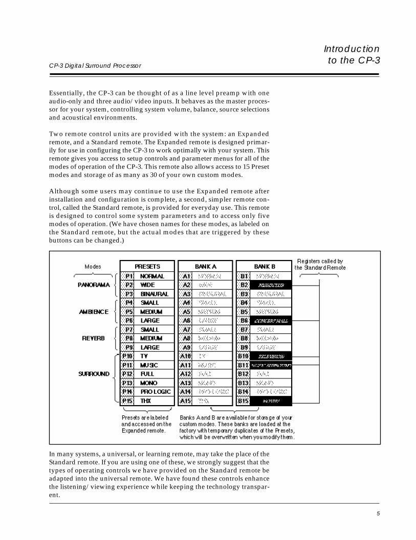
Two remote control units are provided with the system: an Expandedremote, and a Standard remote. The Expanded remote is designed primar-ily for use in configuring the CP-3 to work optimally with your system. Thisremote gives you access to setup controls and parameter menus for all of themodes of operation of the CP-3. This remote also allows access to 15 Presetmodes and storage of as many as 30 of your own custom modes.
Although some users may continue to use the Expanded remote afterinstallation and configuration is complete, a second, simpler remote con-trol, called the Standard remote, is provided for everyday use. This remoteis designed to control some system parameters and to access only fivemodes of operation. (We have chosen names for these modes, as labeled onthe Standard remote, but the actual modes that are triggered by thesebuttons can be changed.)
In many systems, a universal, or learning remote, may take the place of theStandard remote. If you are using one of these, we strongly suggest that thetypes of operating controls we have provided on the Standard remote beadapted into the universal remote. We have found these controls enhancethe listening/viewing experience while keeping the technology transpar-ent.
7
CP-3 Digital Surround Processor2
Controls andIndicators
The Front Panel
Installation andCalibration
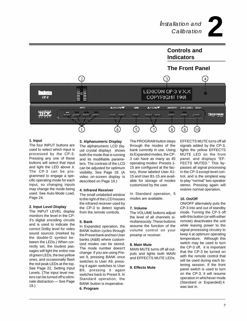
The PROGRAM button stepsthrough the modes of thebank currently in use. Usingits Expanded modes, the CP-3 can have as many as 45operating modes: Presets 1-15 are configured at the fac-tory, those labeled User A1-15 and User B1-15 are avail-able for storage of modescustomized by the user.
In Standard operation, 5modes are available.
7. VolumeThe VOLUME buttons adjustthe level of all channels si-multaneously. These buttonsassume the function of thevolume control on yourpreamp or receiver.
8. Main MuteMAIN MUTE turns off all out-puts and lights both MAINand EFFECTS MUTE LEDs.
9. Effects Mute
3. Alphanumeric DisplayThe alphanumeric LCD (liq-uid crystal display) showsboth the mode that is runningand its modifiable parame-ters. The contrast of the LCDcan be adjusted for optimumvisibility. See Page 18. (Avideo on-screen display isdescribed on Page 19.)
4. Infrared ReceiverThe small unlabeled windowto the right of the LCD housesthe infrared receiver used bythe CP-3 to detect signalsfrom the remote controls.
5. BankIn Expanded operation, theBANK button cycles throughthe Preset bank and two Userbanks (A&B) where custom-ized modes can be stored.The mode number doesn'tchange: if you are using Pre-set 9, pressing BANK onceswitches to User A9, press-ing it again switches to UserB9, pressing it againswitches back to Preset 9. InStandard operation, theBANK button is inoperative.6. Program
1. InputThe four INPUT buttons areused to select which input isprocessed by the CP-3.Pressing any one of thesebuttons will select that inputand light the LED above it.The CP-3 can be pro-grammed to engage a spe-cific operating mode for eachinput, so changing inputsmay change the mode beingused. See Auto-Mode Load,Page 24.
2. Input Level DisplayThe INPUT LEVEL displaymonitors the level in the CP-3's digital encoding circuitsand is used to indicate thecorrect Dolby level for videosound sources (marked bythe double-D symbol be-tween the LEDs.) When cor-rectly set, the loudest pas-sages will light the entire rowof green LEDs, the two yellowones, and occasionally flashthe red peak LEDs at the top.See Page 22, Setting InputLevels. (The input level me-ters can be turned off to elimi-nate distraction — See Page19.)
EFFECTS MUTE turns off allsignals added by the CP-3,lights the yellow EFFECTSMUTE LED on the frontpanel, and displays “EF-FECTS MUTED.” This by-passes all signal processingin the CP-3 except level con-trol, and is the simplest wayto play “normal” two-speakerstereo. Pressing again willrestore normal operation.
10. On/OffON/OFF alternately puts theCP-3 into and out of standbymode. Turning the CP-3 offwith this button (or with eitherremote) deactivates the unitwhile leaving power to thesignal processing circuitry tokeep it at optimum operatingtemperature. Although thisswitch may be used to turnthe CP-3 off, it is importantthat the CP-3 be turned onwith the remote control thatwill be used during each lis-tening session. If the frontpanel switch is used to turnon the CP-3, it will resumeoperation in whichever mode(Standard or Expanded) itwas last in.
8
Lexicon
The Rear Panel
Controls andIndicators
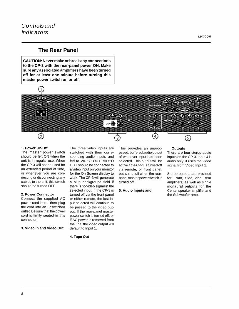
CAUTION: Never make or break any connectionsto the CP-3 with the rear-panel power ON. Makesure any associated amplifiers have been turnedoff for at least one minute before turning thismaster power switch on or off.
1. Power On/OffThe master power switchshould be left ON when theunit is in regular use. Whenthe CP-3 will not be used foran extended period of time,or whenever you are con-necting or disconnecting anycables to the unit, this switchshould be turned OFF.
2. Power ConnectorConnect the supplied ACpower cord here, then plugthe cord into an unswitchedoutlet. Be sure that the powercord is firmly seated in thisconnector.
3. Video In and Video Out
The three video inputs areswitched with their corre-sponding audio inputs andfed to VIDEO OUT. VIDEOOUT should be connected toa video input on your monitorfor the On Screen display towork. The CP-3 will generatea blue background field ifthere is no video signal in theselected input. If the CP-3 isturned off via the front panelor either remote, the last in-put selected will continue tobe passed to the video out-put. If the rear-panel masterpower switch is turned off, orif AC power is removed fromthe unit, the video output willdefault to Input 1.
4. Tape Out
This provides an unproc-essed, buffered audio outputof whatever input has beenselected. This output will beactive if the CP-3 is turned offvia remote, or front panel,but is shut off when the rear-panel master power switch isturned off.
5. Audio Inputs and
OutputsThere are four stereo audioinputs on the CP-3. Input 4 isaudio only; it uses the videosignal from Video Input 1.
Stereo outputs are providedfor Front, Side, and Rearamplifiers, as well as singlemonaural outputs for theCenter speaker amplifier andthe Subwoofer amp.
9
CP-3 Digital Surround Processor
Controls andIndicators
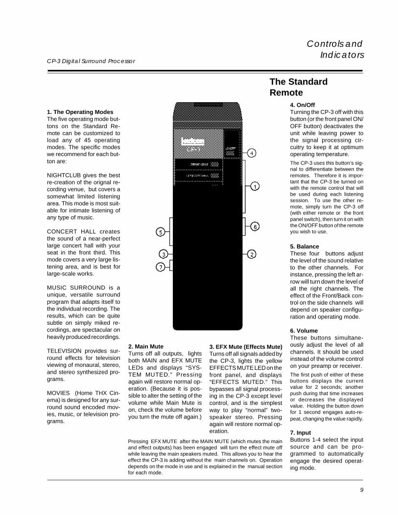
2. Main MuteTurns off all outputs, lightsboth MAIN and EFX MUTELEDs and displays “SYS-TEM MUTED.” Pressingagain will restore normal op-eration. (Because it is pos-sible to alter the setting of thevolume while Main Mute ison, check the volume beforeyou turn the mute off again.)
3. EFX Mute (Effects Mute)Turns off all signals added bythe CP-3, lights the yellowEFFECTS MUTE LED on thefront panel, and displays“EFFECTS MUTED.” Thisbypasses all signal process-ing in the CP-3 except levelcontrol, and is the simplestway to play “normal” two-speaker stereo. Pressingagain will restore normal op-eration.
The StandardRemote
1. The Operating ModesThe five operating mode but-tons on the Standard Re-mote can be customized toload any of 45 operatingmodes. The specific modeswe recommend for each but-ton are:
NIGHTCLUB gives the bestre-creation of the orignal re-cording venue, but covers asomewhat limited listeningarea. This mode is most suit-able for intimate listening ofany type of music.
CONCERT HALL createsthe sound of a near-perfectlarge concert hall with yourseat in the front third. Thismode covers a very large lis-tening area, and is best forlarge-scale works.
MUSIC SURROUND is aunique, versatile surroundprogram that adapts itself tothe individual recording. Theresults, which can be quitesubtle on simply miked re-cordings, are spectacular onheavily produced recordings.
TELEVISION provides sur-round effects for televisionviewing of monaural, stereo,and stereo synthesized pro-grams.
MOVIES (Home THX Cin-ema) is designed for any sur-round sound encoded mov-ies, music, or television pro-grams.
4. On/OffTurning the CP-3 off with thisbutton (or the front panel ON/OFF button) deactivates theunit while leaving power tothe signal processing cir-cuitry to keep it at optimumoperating temperature.
The CP-3 uses this button’s sig-nal to differentiate between theremotes. Therefore it is impor-tant that the CP-3 be turned onwith the remote control that willbe used during each listeningsession. To use the other re-mote, simply turn the CP-3 off(with either remote or the frontpanel switch), then turn it on withthe ON/OFF button of the remoteyou wish to use.
5. BalanceThese four buttons adjustthe level of the sound relativeto the other channels. Forinstance, pressing the left ar-row will turn down the level ofall the right channels. Theeffect of the Front/Back con-trol on the side channels willdepend on speaker configu-ration and operating mode.
6. VolumeThese buttons simultane-ously adjust the level of allchannels. It should be usedinstead of the volume controlon your preamp or receiver.
The first push of either of thesebuttons displays the currentvalue for 2 seconds; anotherpush during that time increasesor decreases the displayedvalue. Holding the button downfor 1 second engages auto-re-peat, changing the value rapidly.
7. InputButtons 1-4 select the inputsource and can be pro-grammed to automaticallyengage the desired operat-ing mode.
Pressing EFX MUTE after the MAIN MUTE (which mutes the mainand effect outputs) has been engaged will turn the effect mute offwhile leaving the main speakers muted. This allows you to hear theeffect the CP-3 is adding without the main channels on. Operationdepends on the mode in use and is explained in the manual sectionfor each mode.
10
Lexicon
Controls andIndicators
The ExpandedRemote
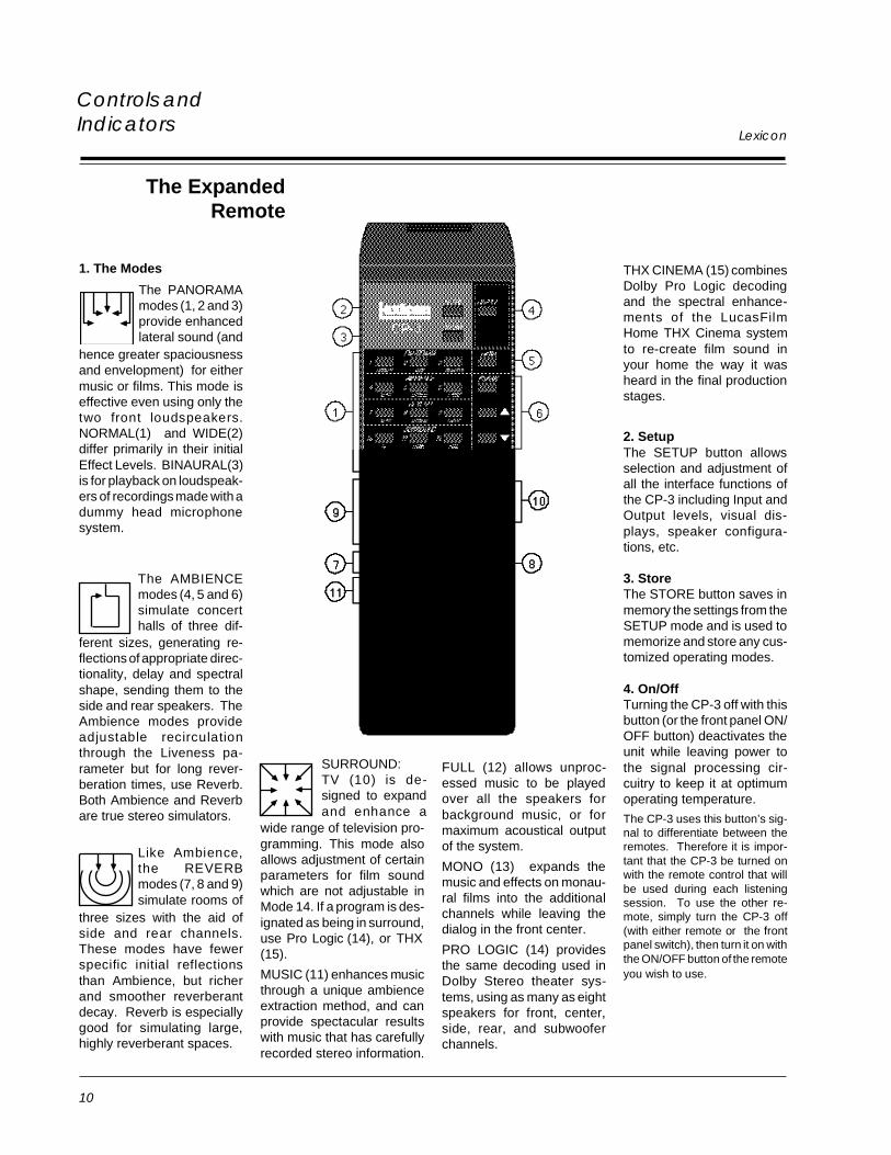
1. The Modes THX CINEMA (15) combinesDolby Pro Logic decodingand the spectral enhance-ments of the LucasFilmHome THX Cinema systemto re-create film sound inyour home the way it washeard in the final productionstages.
2. SetupThe SETUP button allowsselection and adjustment ofall the interface functions ofthe CP-3 including Input andOutput levels, visual dis-plays, speaker configura-tions, etc.
3. StoreThe STORE button saves inmemory the settings from theSETUP mode and is used tomemorize and store any cus-tomized operating modes.
4. On/OffTurning the CP-3 off with thisbutton (or the front panel ON/OFF button) deactivates theunit while leaving power tothe signal processing cir-cuitry to keep it at optimumoperating temperature.
The CP-3 uses this button’s sig-nal to differentiate between theremotes. Therefore it is impor-tant that the CP-3 be turned onwith the remote control that willbe used during each listeningsession. To use the other re-mote, simply turn the CP-3 off(with either remote or the frontpanel switch), then turn it on withthe ON/OFF button of the remoteyou wish to use.
The PANORAMAmodes (1, 2 and 3)provide enhancedlateral sound (and
hence greater spaciousnessand envelopment) for eithermusic or films. This mode iseffective even using only thetwo front loudspeakers.NORMAL(1) and WIDE(2)differ primarily in their initialEffect Levels. BINAURAL(3)is for playback on loudspeak-ers of recordings made with adummy head microphonesystem.
The AMBIENCEmodes (4, 5 and 6)simulate concerthalls of three dif-
ferent sizes, generating re-flections of appropriate direc-tionality, delay and spectralshape, sending them to theside and rear speakers. TheAmbience modes provideadjustable recirculationthrough the Liveness pa-rameter but for long rever-beration times, use Reverb.Both Ambience and Reverbare true stereo simulators.
Like Ambience,the REVERBmodes (7, 8 and 9)simulate rooms of
three sizes with the aid ofside and rear channels.These modes have fewerspecific initial reflectionsthan Ambience, but richerand smoother reverberantdecay. Reverb is especiallygood for simulating large,highly reverberant spaces.
SURROUND:TV (10) is de-signed to expandand enhance a
wide range of television pro-gramming. This mode alsoallows adjustment of certainparameters for film soundwhich are not adjustable inMode 14. If a program is des-ignated as being in surround,use Pro Logic (14), or THX(15).
MUSIC (11) enhances musicthrough a unique ambienceextraction method, and canprovide spectacular resultswith music that has carefullyrecorded stereo information.
FULL (12) allows unproc-essed music to be playedover all the speakers forbackground music, or formaximum acoustical outputof the system.
MONO (13) expands themusic and effects on monau-ral films into the additionalchannels while leaving thedialog in the front center.
PRO LOGIC (14) providesthe same decoding used inDolby Stereo theater sys-tems, using as many as eightspeakers for front, center,side, rear, and subwooferchannels.
11
CP-3 Digital Surround Processor
Controls andIndicators
5. BankThe BANK button switchesbetween the three registerbanks: the Presets and thetwo User register Banks (A &B) where customized modesmay be stored. The modenumber doesn’t change: ifyou are using Preset 9,pressing BANK onceswitches to User A9, press-ing BANK again switches toUSER B9, and pressingBANK once more selectsPreset 9.
6. ParameterThe three parameter buttonsallow selection and adjust-ment of variable parameterswithin each mode. PushingPARAM displays the pa-rameter menu with a move-able cursor for 5 seconds;pushing it again before thedisplay changes moves thecursor to the next parameter.Pressing PARAM or willdisplay and adjust the cur-rent parameter (whether ornot PARAM has beenpushed.) A single push of ei-ther of these buttons displaysthe parameter; another pushchanges the parameter byone unit. Holding PARAM or for more than 1 secondcauses the values to changerapidly in an auto-repeatmode.
7. Effects*
and adjust the level of allsignals added by the CP-3.
8. MutesMAIN MUTE turns off all out-puts and lights both MAINand EFX MUTE LEDs. Push-ing EFX MUTE while in sys-tem- mute mode turns theeffects alone back on. EFXMUTE alternately turns offand on all signals added bythe CP-3. Use it to comparethe sound with and withoutCP-3 processing, or as asimple way to play normaltwo-speaker stereo.
9. Balance*BALANCE: The four balancebuttons adjust the levels ofthe rear speakers relative tothe sides and fronts, and theleft/right balance of all speak-ers: front, sides and rear. Itshould be used instead ofthe balance control on yourpreamp or receiver.
10. Volume*
and simultaneously ad-just the level of all channels.These should be used in-stead of the volume controlon your preamp or receiver.
11. InputINPUT buttons 1-4 select theinput source and can be pro-grammed to automaticallyengage the desired operat-ing mode.
*The first push of either of thesebuttons displays the currentvalue for 2 seconds; anotherpush during that time increasesor decreases the displayedvalue. Holding the button downfor 1 second engages auto-re-peat, changing values rapidly.
Note: Unless otherwise indicated, all references to the remote control in this manualrefer to the Expanded Remote.
12
LexiconConnection
Connection
LocationConsiderations
The CP-3 is a highly specialized signal processing computer and requiresspecial care during installation to ensure optimum performance.
The CP-3 may be installed on a shelf or in a standard 19" equipment rack,using rack-mounting hardware available from Lexicon. Observe the fol-lowing precautions:
• Select a dry, well-ventilated location out of direct sunlight.
• Do not stack the CP-3 directly above heat-producing equipment such aspower amplifiers.
• Avoid placing the CP-3 near unshielded TV or FM antennas, cable TVdecoders, or other receivers. The CP-3 may interfere with some FMtuners if it is placed immediately above or below them. Some products,particularly power amplifiers, may cause hum in the CP-3 if they are inclose proximity.
• Make sure the IR receiver window (located above the On/Off switch onthe CP-3 front panel) is unobstructed. The remote control must be in line-of-sight to this receiver for proper operation. If line-of-sight is impracti-cal, an infrared remote repeater can be used. Place the sender/emitter sothat it has an unobstructed path to the CP-3’s IR receiver window. TheCP-3 may be placed in a glass-doored cabinet but smoked glass willmake the front panel Liquid Crystal Display (LCD) difficult to read andwill reduce the sensitivity of the IR receiver.
• Do not mount the CP-3 into walls or ceiling.
The CP-3 is designed to be connected to an uninterrupted AC power line inthe same manner as a VCR or aTV with a clock in it. Like all computers, theCP-3 is sensitive to voltage fluctuations. We therefore recommend the useof an AC line filter to protect against line surges, or the installation of a lineconditioner to protect against under voltage (brownouts) as well as over-voltage conditions. A lithium battery prevents loss of information stored inthe CP-3 in the event of power loss. This battery should not need replace-ment for 5-7 years. As it is not user-replaceable, please contact Lexicon oryour local dealer for service.
The CP-3 has a master power switch on the rear panel above the IECstandard AC power receptacle. This switch may be left ON continuouslywhen the unit is in regular use. When the CP-3 will not be used for anextended period of time, or whenever you are connecting or disconnectingany cables to the unit, this switch should be turned OFF.
Connect the power cable to the CP-3, then plug the power cord into a walloutlet or into an unswitched outlet on the back of your preamplifier. Be surethat the power cord is firmly seated in the connector on the rear panel of theCP-3.
AC Connections
13
CP-3 Digital Surround ProcessorConnection
Wiring Considerations
Audio/Video CablesThere is controversy over the audible effects of different types of intercon-nects. Good engineering practices have minimized the effect that cablesmight have on the inputs and outputs of the CP-3 — but feel free to evaluatedifferent interconnects in your system. If you want to do some tweaking, beconscious of the mechanical stress from repeated insertion and overly tightconnectors, and the possibly corrosive nature of some contact-enhancingfluids.
Note that the use of audio cables for video applications may cause signaldegradation, and is not recommended. For video connections, please useonly cables that are designed for video applications — these have differentimpedance characteristics than cables approved for audio applications.
Both audio and video cables should be kept as short as possible.
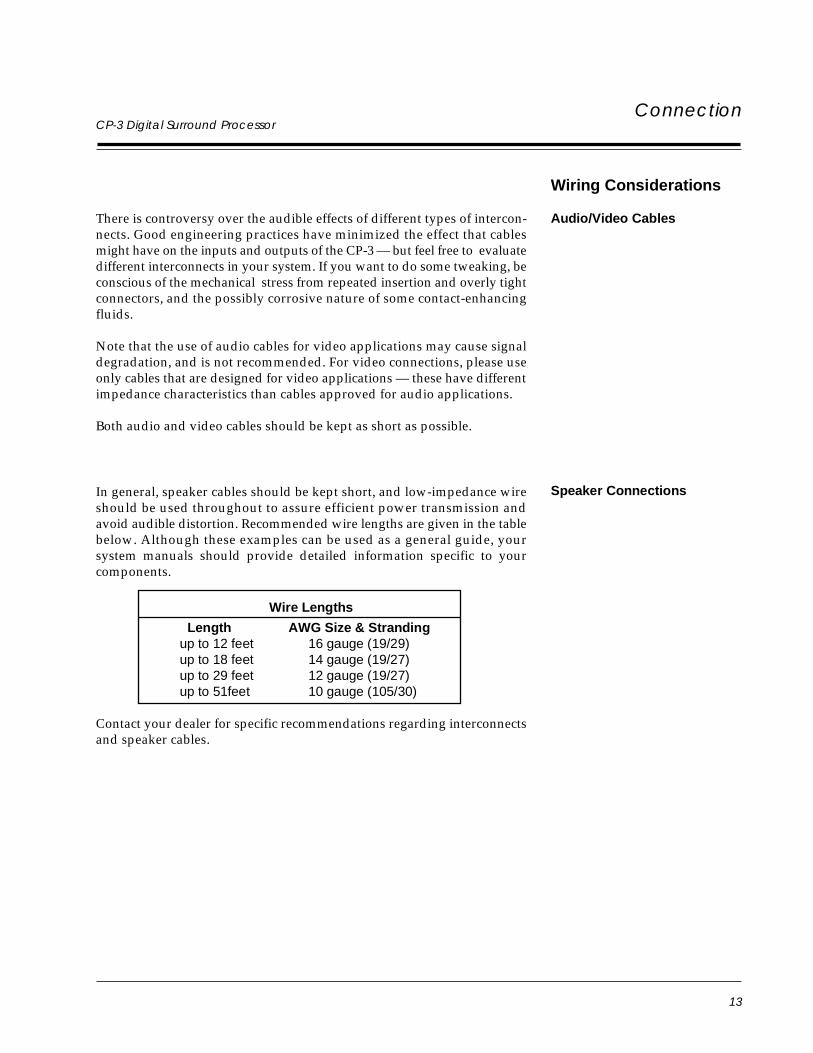
In general, speaker cables should be kept short, and low-impedance wireshould be used throughout to assure efficient power transmission andavoid audible distortion. Recommended wire lengths are given in the tablebelow. Although these examples can be used as a general guide, yoursystem manuals should provide detailed information specific to yourcomponents.
Wire Lengths
Length AWG Size & Strandingup to 12 feet 16 gauge (19/29)up to 18 feet 14 gauge (19/27)up to 29 feet 12 gauge (19/27)up to 51feet 10 gauge (105/30)
Contact your dealer for specific recommendations regarding interconnectsand speaker cables.
Speaker Connections
14
LexiconConnection
Audio/VideoConnections
Before making any connections, turn off ALL audio and video components,including individual power amplifiers. (Unplug any preamps and poweramps that don’t have power switches.)
The CP-3 is designed to function as the control center of the system, selectinginputs and controlling the volume of all speakers in the system. There areseveral ways to integrate the CP-3 into the system, but they basically fall intotwo categories: those where the CP-3 is connected directly to all of theamplifiers in the room, and those where the CP-3 is connected into a tape orsignal processor loop of a preamp or receiver.
As most systems which use the CP-3 are likely to be fairly complex, one ofthe design goals should be to make the entire system intuitive to use. If thereare no more than four line level (not a turntable) sources, it is easiest to hookthem directly to the inputs of the CP-3, and to connect all of the systemamplifiers to the CP-3 outputs. If a mono source is used (such as an olderVCR), a Y-connector should be used to connect to both left and right audioinputs on the CP-3.
Many installations will have more than four sources in the system. Apreamp, or A/V switcher, can handle the additional components — andpossibly add some additional dubbing capabilities. A preamp has theadvantage of a built-in phono amp, and many include decent tone controlsas well. The disadvantages include: a redundant gain stage, another volumecontrol that can be set incorrectly, forfeit of remote switching and loss of theCP-3 programmable input functions for the sources connected through thepreamp. An A/V Switcher may yield more dubbing flexibility, and shouldbe considered if there is no turntable in the system.
You may choose to connect the CP-3 in the tape monitor, or externalprocessor loop of a preamp, allowing you to completey bypass the CP-3.This, however, will make the system somewhat more complicated tooperate, and adds a gain stage (the preamp) that is not needed.
CAUTION: The CP-3 Tape Out output is not a tape monitor circuit.The audio input selected is always fed directly to Tape Out. If a tapedeck is connected to this output and one of the inputs, and thatinput is selected, a feedback loop will result. This can damage theamplifiers, the speakers, and your ears.
15
CP-3 Digital Surround Processor
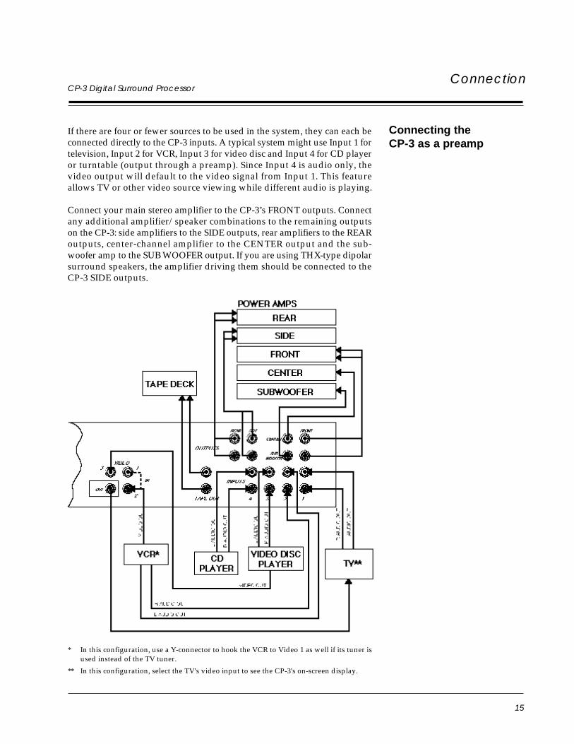
If there are four or fewer sources to be used in the system, they can each beconnected directly to the CP-3 inputs. A typical system might use Input 1 fortelevision, Input 2 for VCR, Input 3 for video disc and Input 4 for CD playeror turntable (output through a preamp). Since Input 4 is audio only, thevideo output will default to the video signal from Input 1. This featureallows TV or other video source viewing while different audio is playing.
Connect your main stereo amplifier to the CP-3’s FRONT outputs. Connectany additional amplifier/speaker combinations to the remaining outputson the CP-3: side amplifiers to the SIDE outputs, rear amplifiers to the REARoutputs, center-channel amplifier to the CENTER output and the sub-woofer amp to the SUB WOOFER output. If you are using THX-type dipolarsurround speakers, the amplifier driving them should be connected to theCP-3 SIDE outputs.
Connecting theCP-3 as a preamp
Connection
* In this configuration, use a Y-connector to hook the VCR to Video 1 as well if its tuner isused instead of the TV tuner.
** In this configuration, select the TV's video input to see the CP-3's on-screen display.
16
Lexicon
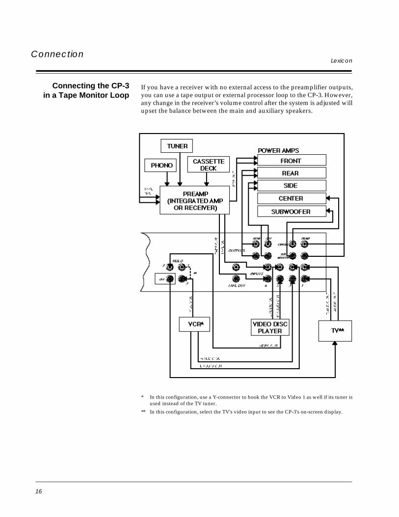
Connecting the CP-3in a Tape Monitor Loop
If you have a receiver with no external access to the preamplifier outputs,you can use a tape output or external processor loop to the CP-3. However,any change in the receiver’s volume control after the system is adjusted willupset the balance between the main and auxiliary speakers.
Connection
* In this configuration, use a Y-connector to hook the VCR to Video 1 as well if its tuner isused instead of the TV tuner.
** In this configuration, select the TV's video input to see the CP-3's on-screen display.

17
CP-3 Digital Surround Processor
Video ConnectionsThe CP-3 has three video inputs and one video output. The inputs arelabeled VIDEO IN 1, 2, and 3, and are switched along with audio inputs 1,2, and 3 via the front panel or either remote. (Audio Input 4 will use the videosignal from Video Input 1.) These inputs are designed for standard NTSCcomposite video signals such as those found at the outputs of video discplayers and VCRs.
If the CP-3 is turned off via remote or front panel, the last selected videoinput will continue to be fed to the output (the audio will be muted), so theCP-3 need not be left on, for example, for simple TV viewing. If the masterpower switch on the CP-3 rear panel is turned off, or if power is removedfrom the CP-3, the unit will default to Input 1 for audio and video, and willcontinue to pass that signal through to the output.
Connection
NOTE: The CP-3 video inputs are designed for NTSC "M" compositevideo signals. The video circuitry is capable of overlaying text on theincoming video signal; it is also capable of generating its own blue textbackground in the absence of an incoming video signal. Even though thevideo circuitry is designed for NTSC only, it can synchronize to incomingPAL and SECAM composite video signals and overlay text on the picture.In doing this, however, the text will lose sharpness, especially in SECAM.
18
Lexicon
LCD Adjustment Depending on the location of the CP-3 in your room, you may need to adjustthe front panel Liquid Crystal Display (LCD) for optimum viewing.
To adjust this display, press the SETUP key on the Expanded Remote. TheCP-3 is now in SETUP mode. Within this mode, operations are carried outusing the three PARAM buttons and STORE.
The LCD will now read:
S E T U P M E N U> I N P U T S
Press PARAM to step to the DISPLAY ADJUST menu, then press PARAM. The LCD will now read:
D I S P L A Y M E N U> O S D P O S I T I O N
Pressing PARAM twice will step to the following display:
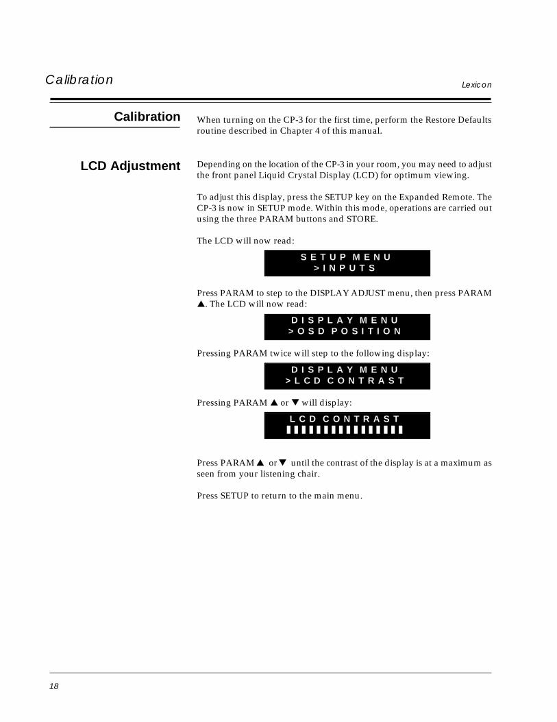
D I S P L A Y M E N U> L C D C O N T R A S T
Pressing PARAM or will display:
L C D C O N T R A S T
Press PARAM or until the contrast of the display is at a maximum asseen from your listening chair.
Press SETUP to return to the main menu.
When turning on the CP-3 for the first time, perform the Restore Defaultsroutine described in Chapter 4 of this manual.
Calibration
Calibration
19
CP-3 Digital Surround Processor
The VideoOn-Screen Display
In addition to the front-panel LCD, the CP-3 contains a character generatorfor a video overlay display on television sets. Since the On-Screen Displayis capable of showing the full menu of options available at any point,calibration of the system is faster and easier if the CP-3 video output isconnected to a video input on a television monitor.
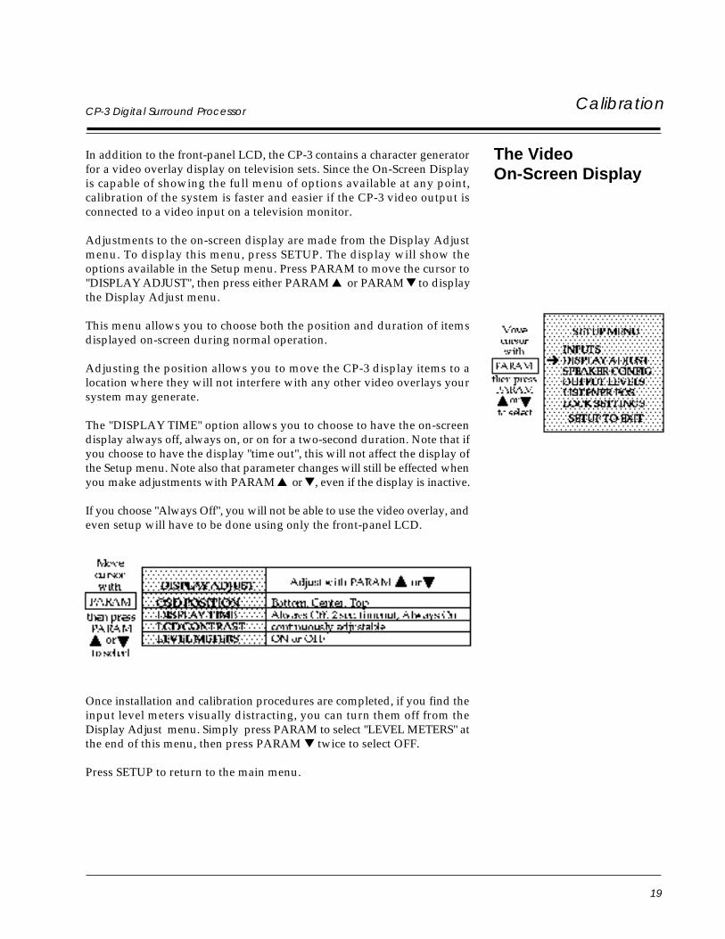
Adjustments to the on-screen display are made from the Display Adjustmenu. To display this menu, press SETUP. The display will show theoptions available in the Setup menu. Press PARAM to move the cursor to"DISPLAY ADJUST", then press either PARAM or PARAM to displaythe Display Adjust menu.
This menu allows you to choose both the position and duration of itemsdisplayed on-screen during normal operation.
Adjusting the position allows you to move the CP-3 display items to alocation where they will not interfere with any other video overlays yoursystem may generate.
The "DISPLAY TIME" option allows you to choose to have the on-screendisplay always off, always on, or on for a two-second duration. Note that ifyou choose to have the display "time out", this will not affect the display ofthe Setup menu. Note also that parameter changes will still be effected whenyou make adjustments with PARAM or , even if the display is inactive.
If you choose "Always Off", you will not be able to use the video overlay, andeven setup will have to be done using only the front-panel LCD.
Calibration
Once installation and calibration procedures are completed, if you find theinput level meters visually distracting, you can turn them off from theDisplay Adjust menu. Simply press PARAM to select "LEVEL METERS" atthe end of this menu, then press PARAM twice to select OFF.
Press SETUP to return to the main menu.
20
LexiconCalibration
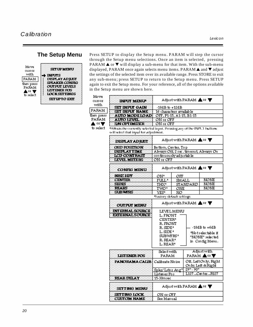
Press SETUP to display the Setup menu. PARAM will step the cursorthrough the Setup menu selections. Once an item is selected, pressingPARAM or will display a sub-menu for that item. With the sub-menudisplayed, PARAM once again selects menu items. PARAM and adjustthe settings of the selected item over its available range. Press STORE to exitany sub-menu; press SETUP to return to the Setup menu. Press SETUPagain to exit the Setup menu. For your reference, all of the options availablein the Setup menu are shown here.
The Setup Menu
21
CP-3 Digital Surround Processor Calibration
Setting the SpeakerConfiguration
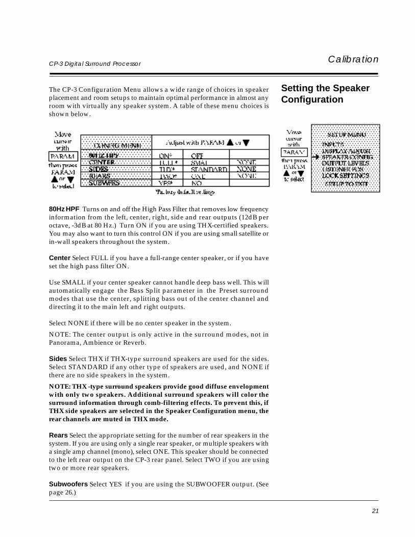
The CP-3 Configuration Menu allows a wide range of choices in speakerplacement and room setups to maintain optimal performance in almost anyroom with virtually any speaker system. A table of these menu choices isshown below.
80Hz HPF Turns on and off the High Pass Filter that removes low frequencyinformation from the left, center, right, side and rear outputs (12dB peroctave, -3dB at 80 Hz.) Turn ON if you are using THX-certified speakers.You may also want to turn this control ON if you are using small satellite orin-wall speakers throughout the system.
Center Select FULL if you have a full-range center speaker, or if you haveset the high pass filter ON.
Use SMALL if your center speaker cannot handle deep bass well. This willautomatically engage the Bass Split parameter in the Preset surroundmodes that use the center, splitting bass out of the center channel anddirecting it to the main left and right outputs.
Select NONE if there will be no center speaker in the system.
NOTE: The center output is only active in the surround modes, not inPanorama, Ambience or Reverb.
Sides Select THX if THX-type surround speakers are used for the sides.Select STANDARD if any other type of speakers are used, and NONE ifthere are no side speakers in the system.
NOTE: THX -type surround speakers provide good diffuse envelopmentwith only two speakers. Additional surround speakers will color thesurround information through comb-filtering effects. To prevent this, ifTHX side speakers are selected in the Speaker Configuration menu, therear channels are muted in THX mode.
Rears Select the appropriate setting for the number of rear speakers in thesystem. If you are using only a single rear speaker, or multiple speakers witha single amp channel (mono), select ONE. This speaker should be connectedto the left rear output on the CP-3 rear panel. Select TWO if you are usingtwo or more rear speakers.
Subwoofers Select YES if you are using the SUBWOOFER output. (Seepage 26.)
22
LexiconCalibration
SettingInput Levels
There are four inputs on the CP-3. Inputs 1, 2 and 3 switch audio and video;Input 4 switches audio only and outputs the video signal from Video Input1. Each input can be assigned an individual gain level to compensate forsources with different output levels. You can create a name that will bedisplayed on the screen whenever that input is selected and have each inputautomatically engage the proper operating mode. For example, Input 1could have an input level gain of +6dB, display "Video Disc" on the screen,and engage the Home THX Cinema mode.
To obtain maximum performance from the CP-3 (or almost any other signalprocessor) it is important that the unit be driven to its full input levelwithout overloading. Despite industry attempts at standardization, there isstill a wide disparity of output levels among different sources. For example,Compact Discs are often as much as 10-15dB higher in level than video discs.To compensate for this, each of the four inputs on the CP-3 can be assigneda different input gain, assuring optimum performance and consistentvolume, regardless of the source selected. The CP-3 can also be set tomonitor the input level and automatically optimize the input gain. The CP-3's auto-level and signal-to-noise optimization systems can be defeated forspecial situations. (The S/N Optimizer is deliberately turned off in theAmbience and Reverb modes.)
Note: When calibrating the input levels, set the system volume to -25dB orhigher to ensure optimum meter accuracy. You may engage the SystemMute if you do not want to hear the input.
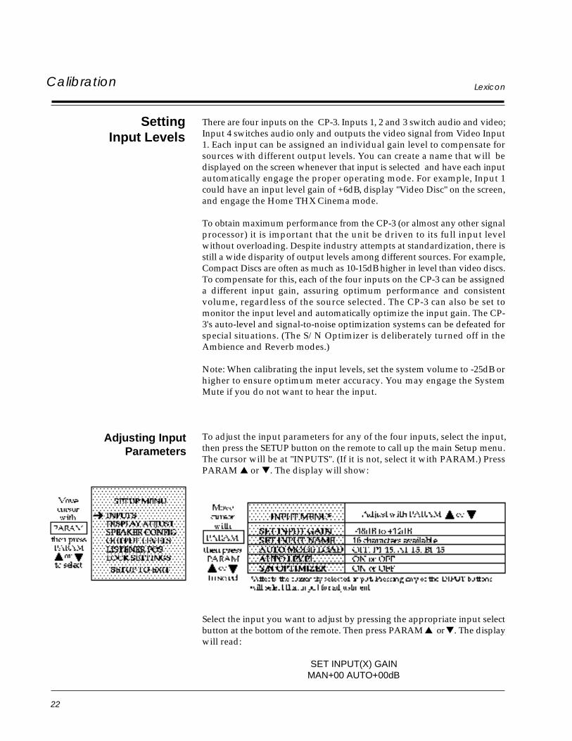
To adjust the input parameters for any of the four inputs, select the input,then press the SETUP button on the remote to call up the main Setup menu.The cursor will be at "INPUTS". (If it is not, select it with PARAM.) PressPARAM or . The display will show:
Select the input you want to adjust by pressing the appropriate input selectbutton at the bottom of the remote. Then press PARAM or . The displaywill read:
SET INPUT(X) GAINMAN+00 AUTO+00dB
Adjusting InputParameters
23
CP-3 Digital Surround Processor Calibration
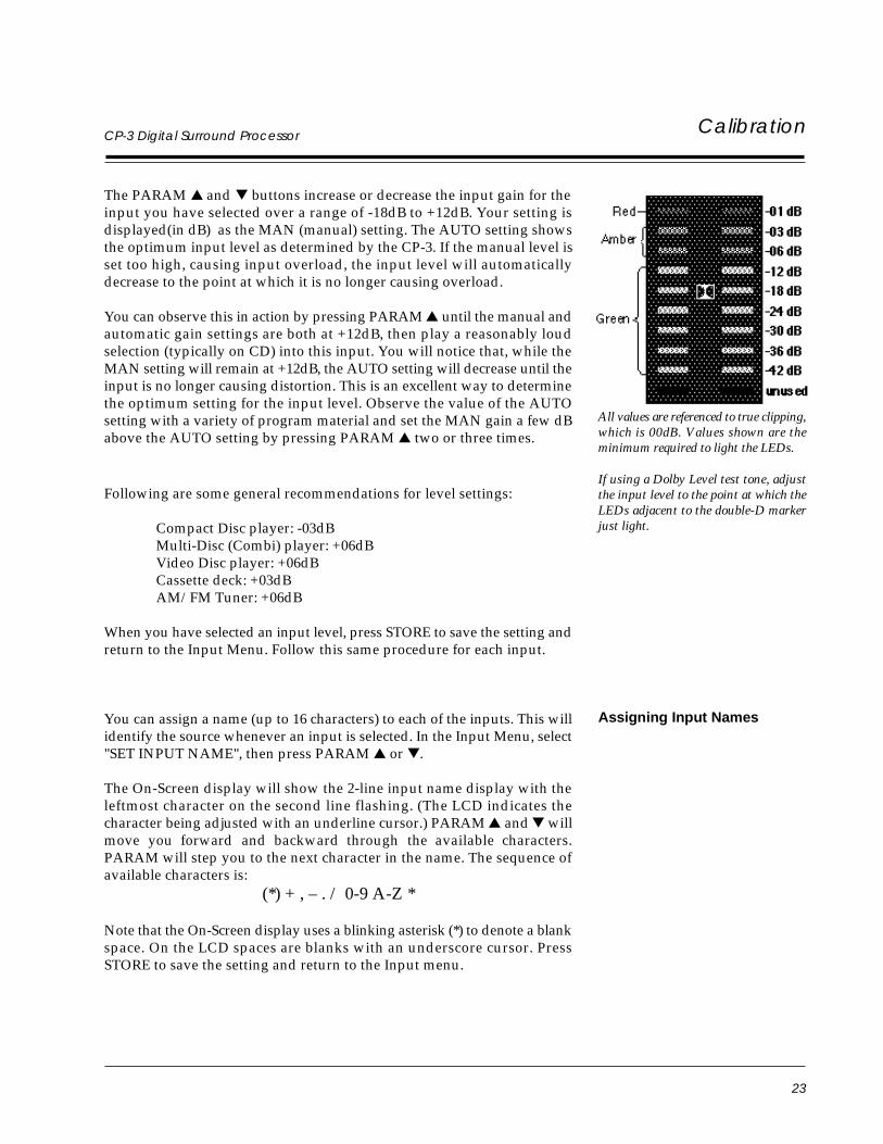
The PARAM and buttons increase or decrease the input gain for theinput you have selected over a range of -18dB to +12dB. Your setting isdisplayed(in dB) as the MAN (manual) setting. The AUTO setting showsthe optimum input level as determined by the CP-3. If the manual level isset too high, causing input overload, the input level will automaticallydecrease to the point at which it is no longer causing overload.
You can observe this in action by pressing PARAM until the manual andautomatic gain settings are both at +12dB, then play a reasonably loudselection (typically on CD) into this input. You will notice that, while theMAN setting will remain at +12dB, the AUTO setting will decrease until theinput is no longer causing distortion. This is an excellent way to determinethe optimum setting for the input level. Observe the value of the AUTOsetting with a variety of program material and set the MAN gain a few dBabove the AUTO setting by pressing PARAM two or three times.
Following are some general recommendations for level settings:
Compact Disc player: -03dBMulti-Disc (Combi) player: +06dBVideo Disc player: +06dBCassette deck: +03dBAM/FM Tuner: +06dB
When you have selected an input level, press STORE to save the setting andreturn to the Input Menu. Follow this same procedure for each input.
You can assign a name (up to 16 characters) to each of the inputs. This willidentify the source whenever an input is selected. In the Input Menu, select"SET INPUT NAME", then press PARAM or .
The On-Screen display will show the 2-line input name display with theleftmost character on the second line flashing. (The LCD indicates thecharacter being adjusted with an underline cursor.) PARAM and willmove you forward and backward through the available characters.PARAM will step you to the next character in the name. The sequence ofavailable characters is:
(*) + , – . / 0-9 A-Z *
Note that the On-Screen display uses a blinking asterisk (*) to denote a blankspace. On the LCD spaces are blanks with an underscore cursor. PressSTORE to save the setting and return to the Input menu.
All values are referenced to true clipping,which is 00dB. Values shown are theminimum required to light the LEDs.
If using a Dolby Level test tone, adjustthe input level to the point at which theLEDs adjacent to the double-D markerjust light.
Assigning Input Names
24
LexiconCalibration
Auto-Mode Load(Automatic Input Mode
Loading)
Auto-Mode Load determines which operating mode will be engaged whena specific input is selected. For example, the input for a video disc playerwould load the Home THX Cinema mode, while the input for a CD playerwould load the Music Surround mode. Any of the preset modes or any ofthe CP-3's 30 User Registers can be selected — or the current mode canremain unchanged. You can, of course, change the operating mode you arelistening to, but if AUTO MODE LOAD is ON, pressing the same inputbutton again will reload the assigned operating mode.
To set Auto-Mode Load, go to the Input menu, select "AUTO MODELOAD", then press PARAM or . The display will show which mode isautomatically loaded. If the display reads "AUTO MODE LOAD OFF",selecting this input will not change the operating mode and the CP-3 willremain in the same operating mode it was in before this particular input wasselected. To change the mode, press PARAM or to scroll through theavailable operating modes. The choices are: OFF, Presets 1-15, Bank A 1-15,Bank B 1-15. Since the Standard remote uses modes stored in User RegisterB, we recommend selecting one of these five modes for Auto-Mode Load.
The Input Auto-Level function (see discussion under Setting Input Levels)is normally ON. This can be defeated by using PARAM to move the cursorto select the "AUTO LEVEL" parameter, then pressing PARAM twice.Now, pressing PARAM will turn this function ON, pressing PARAM will turn it OFF. Press STORE to save and return to the Input menu.
In addition to controlling the input level, the CP-3 constantly monitors andadjusts the internal signal levels to maximize the signal-to-noise ratio.Theoretically, if the manual input level is set far too high, and you havemusic or a soundtrack with a very long soft section followed by, say acannon shot, this may result in a few milliseconds of input clipping.Although we have yet to find a musical selection or a film soundtrack thatdoes this (and, hopefully, the input level will not be grossly misadjusted tobegin with) we have provided a control so that you can turn this functionoff. Under normal operating situations, we recommend it be left on.
The Signal-to-Noise Optimization function is not available in the Reverband Ambience modes. In other modes it is normally ON. This function canbe defeated by using PARAM to move the cursor to select the "S/NOPTIMIZER" parameter, then pressing PARAM twice. Now, pressingPARAM will turn this function ON, pressing PARAM will turn it OFF.Press STORE to save and return to the Input menu.
Note that the S/N Optimizer is selectable for each of the four inputs.
Auto-Level
Signal-to-Noise Optimization
25
CP-3 Digital Surround Processor Calibration
SettingOutput Levels
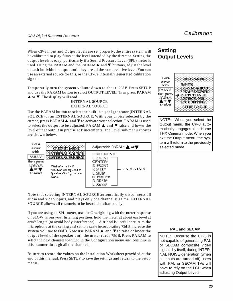
NOTE: Because the CP-3 isnot capable of generating PALor SECAM composite videosignals by itself, during INTER-NAL NOISE generation (whenall inputs are turned off) userswith PAL or SECAM TVs willhave to rely on the LCD whenadjusting Output Levels.
When CP-3 Input and Output levels are set properly, the entire system willbe calibrated to play films at the level intended by the director. Setting theoutput levels is easy, particularly if a Sound Pressure Level (SPL) meter isused. Using the PARAM and the PARAM and buttons, adjust the levelof each individual output until they are all the same relative level. You canuse an external source for this, or the CP-3's internally generated calibrationsignal.
Temporarily turn the system volume down to about -20dB. Press SETUPand use the PARAM button to select OUTPUT LEVEL. Then press PARAM or . The display will read:
INTERNAL SOURCEEXTERNAL SOURCE
Use the PARAM button to select the built-in signal generator (INTERNALSOURCE) or an EXTERNAL SOURCE. With your choice selected by thecursor, press PARAM and to activate your selection. PARAM is usedto select the output to be adjusted; PARAM and raise and lower thelevel of that output in precise 1dB increments. The Level sub-menu choicesare shown below.
Note that selecting INTERNAL SOURCE automatically disconnects allaudio and video inputs, and plays only one channel at a time. EXTERNALSOURCE allows all channels to be heard simultaneously.
If you are using an SPL meter, use the C-weighting with the meter responseon SLOW. From your listening position, hold the meter at about ear level atarm's length (to avoid body interference). A tripod is useful here. Aim themicrophone at the ceiling and set to a scale incorporating 75dB. Increase thesystem volume to 00dB. Now use PARAM and to raise or lower theoutput level of the speaker until the meter reads 75dB. Press PARAM toselect the next channel specified in the Configuration menu and continue inthis manner through all the channels.
Be sure to record the values on the Installation Worksheet provided at theend of this manual. Press SETUP to save the settings and return to the Setupmenu.
PAL and SECAM
NOTE: When you select theOutput menu, the CP-3 auto-matically engages the HomeTHX Cinema mode. When youexit the Output menu, the sys-tem will return to the previouslyselected mode.
26
LexiconCalibration
In the absence of an SPL meter, it is possible to set the output level by ear.Use the built-in signal generator in the CP-3 to adjust all volumes to be thesame as they cycle around the various speakers. Depending on timbrevariations between your speakers, this may be difficult to judge, get as closeas you can. The system should be reasonably well balanced, although notactually calibrated for precise playback level matching. With the systemvolume at 0dB, the internal noise source should be at the same level at whichfilm dialog sounds comfortable.
NOTE: If the CP-3 is connected in the tape monitor or signal processorloopof a preamp, integrated amp, or receiver, or if any of the amplifiers used inthe system have gain (volume) controls, the level settings on them will affectthe balance of the CP-3 outputs. Generally, the gain controls of these ampsshould be set at or near maximum. You should record the values of thesecontrols on the Installation Worksheet provided at the end of this manualfor later reference.
The SUBWOOFER output is created by summing the left and right inputs,then filtering out frequencies above 80Hz at a rate of 24dB per octave. Forthe tragically technical, this is a Linkwitz-Riley LPF -6dB @ 80Hz. Many ofthe better subwoofers have their own crossover (complementary low andhigh pass filters) and amp built in. With these, it is often better not to use theCP-3 SUBWOOFER output which has already been filtered. Instead, con-nect the CP-3 main (FRONT) left and right outputs to the inputs of thesubwoofer crossover. Connect the CP-3 SUBWOOFER output to the ampli-fier driving the main speakers. This has the advantage of bi-amping: all thelow bass is handled by the subwoofer; the main speakers handle only mid-bass and up (usually resulting in better-sounding main speakers). If youwant to run the main speakers full range, the sub can be wired in parallel tothe main amp using a Y-connector.
Be sure to turn the 80Hz HPF in the Speaker Config menu to OFF. Since thecenter channel will now be running full range, select SMALL center in theSpeaker Config menu. This turns on the BASS SPLIT parameter in the Presetmodes, splitting low frequencies off the center channel and feeding them tothe left and right front outputs. Remember to adjust this parameter in anyUser registers you program, as it is initially set to BYPASS. A little experi-mentation goes a long way in determining the optimum value for BASSSPLIT. Usually, a cutoff between 63Hz and 140Hz is best. Too high a cutoffwill make some male vocals sound chesty; too low a cutoff causes bass loss.
Now the center channel is rolled off and the main left and right are crossedover by the subwoofer. You do not need to be as concerned with thesurrounds because the Dolby encoder rolls off most of the bass below100Hz. Some films, however, do have substantial LF information in thesurrounds and the CP-3 music modes do not limit low frequencies at all.(Although the effects channels are typically using less than 25% of thepower used in the mains.) Unless you plan on very high sound pressurelevels and want lots of bass, most systems will not require subs on thesechannels. Obviously, the most efficient way to add subs is to utilize thecrossover in the CP-3.
Subwoofers
27
CP-3 Digital Surround Processor Calibration
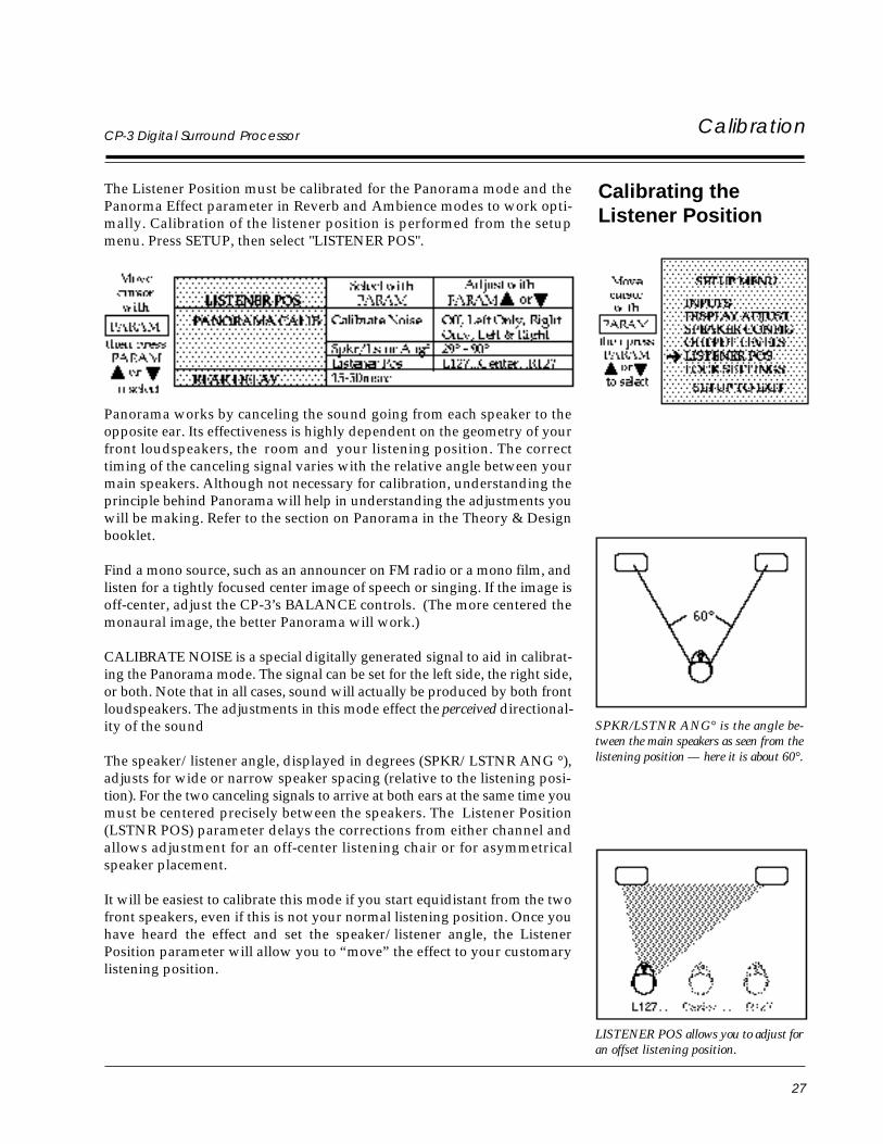
The Listener Position must be calibrated for the Panorama mode and thePanorma Effect parameter in Reverb and Ambience modes to work opti-mally. Calibration of the listener position is performed from the setupmenu. Press SETUP, then select "LISTENER POS".
Calibrating theListener Position
SPKR/LSTNR ANG° is the angle be-tween the main speakers as seen from thelistening position — here it is about 60°.
LISTENER POS allows you to adjust foran offset listening position.
Panorama works by canceling the sound going from each speaker to theopposite ear. Its effectiveness is highly dependent on the geometry of yourfront loudspeakers, the room and your listening position. The correcttiming of the canceling signal varies with the relative angle between yourmain speakers. Although not necessary for calibration, understanding theprinciple behind Panorama will help in understanding the adjustments youwill be making. Refer to the section on Panorama in the Theory & Designbooklet.
Find a mono source, such as an announcer on FM radio or a mono film, andlisten for a tightly focused center image of speech or singing. If the image isoff-center, adjust the CP-3’s BALANCE controls. (The more centered themonaural image, the better Panorama will work.)
CALIBRATE NOISE is a special digitally generated signal to aid in calibrat-ing the Panorama mode. The signal can be set for the left side, the right side,or both. Note that in all cases, sound will actually be produced by both frontloudspeakers. The adjustments in this mode effect the perceived directional-ity of the sound
The speaker/listener angle, displayed in degrees (SPKR/LSTNR ANG °),adjusts for wide or narrow speaker spacing (relative to the listening posi-tion). For the two canceling signals to arrive at both ears at the same time youmust be centered precisely between the speakers. The Listener Position(LSTNR POS) parameter delays the corrections from either channel andallows adjustment for an off-center listening chair or for asymmetricalspeaker placement.
It will be easiest to calibrate this mode if you start equidistant from the twofront speakers, even if this is not your normal listening position. Once youhave heard the effect and set the speaker/listener angle, the ListenerPosition parameter will allow you to “move” the effect to your customarylistening position.
28
LexiconCalibration
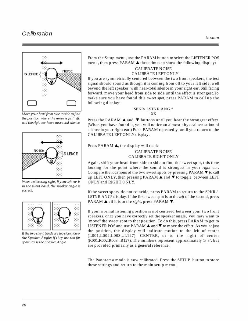
Move your head from side to side to findthe position where the noise is full left,and the right ear hears near total silence.
When calibrating right, if your left ear isin the silent band, the speaker angle iscorrect.
If the two silent bands are too close, lowerthe Speaker Angle; if they are too farapart, raise the Speaker Angle.
From the Setup menu, use the PARAM button to select the LISTENER POSmenu, then press PARAM three times to show the following display:
CALIBRATE NOISE CALIBRATE LEFT ONLY
If you are symmetrically centered between the two front speakers, the testsignal should sound as though it is coming from off to your left side, wellbeyond the left speaker, with near-total silence in your right ear. Still facingforward, move your head from side to side until the effect is strongest.Tomake sure you have found this sweet spot, press PARAM to call up thefollowing display:
SPKR/LSTNR ANG °XX
Press the PARAM and buttons until you hear the strongest effect.(When you have found it, you will notice an almost physical sensation ofsilence in your right ear.) Push PARAM repeatedly until you return to theCALIBRATE LEFT ONLY display.
Press PARAM , the display will read:
CALIBRATE NOISECALIBRATE RIGHT ONLY
Again, shift your head from side to side to find the sweet spot, this timelooking for the point where the sound is strongest in your right ear.Compare the locations of the two sweet spots by pressing PARAM to callup LEFT ONLY, then pressing PARAM and to toggle between LEFTONLY and RIGHT ONLY.
If the sweet spots do not coincide, press PARAM to return to the SPKR./LSTNR ANG° display. If the first sweet spot is to the left of the second, pressPARAM ; if it is to the right, press PARAM .
If your normal listening position is not centered between your two frontspeakers, once you have correctly set the speaker angle, you may want to"move" the sweet spot to that position. To do this, press PARAM to get toLISTENER POS and use PARAM and to move the effect. As you adjustthe position, the display will indicate motion to the left of center(L001,L002,L003...L127), CENTER, or to the right of center(R001,R002,R003...R127). The numbers represent approximately 1/3", butare provided primarily as a general reference.
The Panorama mode is now calibrated. Press the SETUP button to storethese settings and return to the main setup menu.
29
CP-3 Digital Surround ProcessorCalibration
Setting Rear Delay
Rear Delay Settings
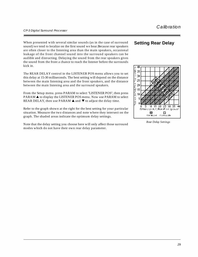
When presented with several similar sounds (as in the case of surroundsound) we tend to localize on the first sound we hear.Because rear speakersare often closer to the listening area than the main speakers, occasionalleakage of the front channel sound into the surround speakers can beaudible and distracting. Delaying the sound from the rear speakers givesthe sound from the front a chance to reach the listener before the surroundskick in.
The REAR DELAY control in the LISTENER POS menu allows you to setthis delay at 15-30 milliseconds. The best setting will depend on the distancebetween the main listening area and the front speakers, and the distancebetween the main listening area and the surround speakers.
From the Setup menu. press PARAM to select "LISTENER POS", then pressPARAM to display the LISTENER POS menu. Now use PARAM to selectREAR DELAY, then use PARAM and to adjust the delay time.
Refer to the graph shown at the right for the best setting for your particularsituation. Measure the two distances and note where they intersect on thegraph. The shaded areas indicate the optimum delay settings.
Note that the delay setting you choose here will only affect those surroundmodes which do not have their own rear delay parameter.
30
LexiconCustomization
Customization
Locking In Settings After you have calibrated and customized the CP-3, there are two additionalsteps recommended to safeguard the settings:
First, document your adjustments on the Installation Worksheet (providedat the end of this manual) if you have not already done so.
Second, consider locking the settings in so that they cannot be inadvertentlychanged. Locking the settings will allow full operation with the Standardremote, but will limit the Expanded remote’s ability to change operatingparameters. Specifically, with the Settings Lock ON, the Expanded remotewill function normally but will not be able to change values in the Setupmenu or any parameters. The PARAM button will function normally, sothe parameters can be selected, but pressing either PARAM or willsimply display the parameter value and yield a "SETTINGS ARE LOCKED"message.
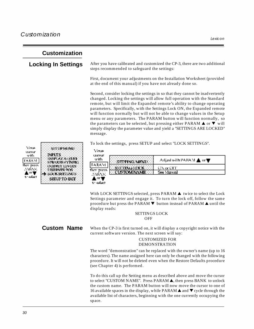
To lock the settings, press SETUP and select "LOCK SETTINGS".
With LOCK SETTINGS selected, press PARAM twice to select the LockSettings parameter and engage it. To turn the lock off, follow the sameprocedure but press the PARAM button instead of PARAM until thedisplay reads:
SETTINGS LOCK OFF
When the CP-3 is first turned on, it will display a copyright notice with thecurrent software version. The next screen will say:
CUSTOMIZED FORDEMONSTRATION
The word "demonstration" can be replaced with the owner's name (up to 16characters). The name assigned here can only be changed with the followingprocedure. It will not be deleted even when the Restore Defaults procedure(see Chapter 4) is performed.
To do this call up the Setting menu as described above and move the cursorto select "CUSTOM NAME". Press PARAM , then press BANK to unlockthe custom name. The PARAM button will now move the cursor to one of16 available spaces in the display, while PARAM and cycle through theavailable list of characters, beginning with the one currently occupying thespace.
Custom Name
31
CP-3 Digital Surround ProcessorCustomization
Custom Modes
At this point an underline character appears in the bottom row of the LCDdisplay. (On the on-screen display, one of the characters of the current namewill flash.) The cursor will move to the leftmost character of the mode name.Now push PARAM or until the character you want appears in thespace. (Holding either button for one second activates an auto-repeat modeto speed you through the list.) All letters are available, in upper case, as aredigits 0-9, a blank space and an assortment of other characters. When thefirst space in the display is correct, press PARAM, use PARAM and toset the second character and repeat until the new name is complete.
Press SETUP to exit to the main Setup menu. Press SETUP again to resumenormal operation.
Lastly, the CP-3 is designed to be operated day to day with the StandardRemote. Unless you are an incorrigible tweaker, simply put the ExpandedRemote away, with its batteries removed for safe keeping.
When the CP-3 is powered up via the Standard remote, it will automaticallyrestrict itself to the five operating modes in User Bank B that correspond tothose listed on the remote. These modes are stored in registers B2, B6, B11,B10, and B15. Since these modes are stored in User registers, it is possibleto change these modes so that a new operating mode is engaged when oneof the five mode buttons on the Standard remote is pressed. For instance,you may choose to have NIGHTCLUB load a small Ambience hall insteadof the default Panorama Wide mode — To do this, simply load the smallAmbience hall into register B2. Of course you can also adjust any of theparameters in the mode. Adjustments will be saved automatically.
Mode: loads register: default preset:
NIGHTCLUB B2 PANORAMA-WIDE
CONCERT HALL B6 AMBIENCE-LARGE HALL
MUSIC SURROUND B11 SURROUND- MUSIC LOGIC
TELEVISION B10 SURROUND-TELEVISION
MOVIES B15 SURROUND-HOME THX
32
LexiconCustomization
Chapter 3 describes the CP-3’s four basic modes and all of their variableparameters. Any changes in the parameters of a mode in the User bank willbe automatically recorded and stored for future use. The CP-3 also allowsyou to store a new version of any Preset or User mode in any User register.
In addition to the 15 Preset modes set at the factory, there are 30 Userregisters (Bank A 1-15 and Bank B 1-15) that can be used to store customizedversions of the original modes. Any of the parameters that can be accessedand changed with the Expanded remote can be used to modify the modes.Left/Right BALANCE and VOLUME settings are considered system para-meters and are not stored with each mode. EFFECT LEVEL, Front/RearBALANCE, and parameters listed in the parameter menu, will be memo-rized in this new mode if it is stored in a User register.
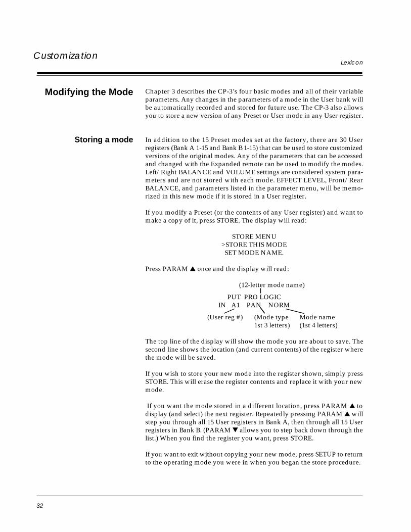
If you modify a Preset (or the contents of any User register) and want tomake a copy of it, press STORE. The display will read:
STORE MENU>STORE THIS MODESET MODE NAME.
Press PARAM once and the display will read:
(12-letter mode name)
PUT PRO LOGICIN A1 PAN NORM
(User reg #) (Mode type Mode name1st 3 letters) (1st 4 letters)
The top line of the display will show the mode you are about to save. Thesecond line shows the location (and current contents) of the register wherethe mode will be saved.
If you wish to store your new mode into the register shown, simply pressSTORE. This will erase the register contents and replace it with your newmode.
If you want the mode stored in a different location, press PARAM todisplay (and select) the next register. Repeatedly pressing PARAM willstep you through all 15 User registers in Bank A, then through all 15 Userregisters in Bank B. (PARAM allows you to step back down through thelist.) When you find the register you want, press STORE.
If you want to exit without copying your new mode, press SETUP to returnto the operating mode you were in when you began the store procedure.
Modifying the Mode
Storing a mode
33
CP-3 Digital Surround Processor Customization
To rename any mode, press the STORE button. The display reads:
STORE MENU>STORE THIS MODESET MODE NAME.
Move the cursor to select "SET MODE NAME". The PARAM button willnow move the cursor to one of twelve available spaces in the display, whilePARAM and cycle through the available list of characters, beginningwith the one currently occupying the space.
At this point an underline character appears in the bottom row of the LCDdisplay. (On the on-screen display, one of the characters of the current namewill flash.) The cursor will move to the leftmost character of the mode name.Now push PARAM or until the character you want appears in thespace. (Holding either button for one second activates an auto-repeat modeto speed you through the list.) All letters are available, in upper case, as aredigits 0-9, a blank space and an assortment of other characters. When thefirst space in the display is correct, press PARAM, use PARAM and toset the second character and repeat until the new name is complete.
Press SETUP to return to the Store menu. Use PARAM to select "STORETHIS MODE", then use PARAM and to step to the register where youwant this mode stored. Once you have selected a location, press STORE.
Note that, if you have renamed a Preset, you must store the newly-namedmode in a User register in order to have your change saved.
Renaming a mode

35
Usingthe CP-3
CP-3 Digital Surround Processor 3Using theModes
The CP-3 contains four basic operating modes: Panorama, Ambience,Reverb and Surround. Each of these modes is labeled on the Expandedremote, with its variations. Pushing one of the buttons numbered 1-15during normal operation will load that mode. Whenever the CP-3 is turnedon, it will load the mode that was running when it was turned off.
Each mode has a number of parameters that you can vary with the threePARAMETER buttons. The parameters for each mode are described later inthis section. Pressing PARAM displays the parameters available for themode you are using, with a cursor marking the currently adjustable pa-rameter. The first time you press either PARAM or , the current valueof the parameter will be displayed. After that, pressing PARAM willincrease the value of the parameter (or turn the function ON), pressingPARAM will decrease the parameter value (or turn the function OFF).This will be true even if you have set the display to time out and theparameter is no longer shown on the screen.
The CP-3 contains a total of 45 mode registers organized into three Banks of15. Each of the 15 mode buttons will load one of the factory Presets labeledon the Expanded remote, or one of the 15 User registers in Bank A or B,depending on which Bank you have chosen. The BANK button togglesbetween the Preset Bank and the two User Banks. For example, if you arerunning USER A 7, pressing BANK will switch to USER B 7, pressing BANKagain will switch to PRESET 7, pressing it again will switch back to USERA 7, and so on. The factory Preset modes are denoted by the label: PRESETin the upper left of the display, with the mode number beneath. The modetitle appears in the right half of the display, with the mode name above andthe variation below.
While running a Preset you can change any of its parameters to see how theyaffect the sound. These changes will be lost when you turn the CP-3 off orwhen you change modes, unless you explicitly store the changes. (See Page32.) Changes made in the value of parameters within a User mode,however, are stored immediately and automatically. This includes set-tings of EFFECT LEVEL and FRONT/REAR BALANCE, but not of theLEFT/RIGHT BALANCE or VOLUME controls. You do not have to per-form any specific storage routine to create a new variation in a User register;it happens whenever you change a parameter.
When the CP-3 leaves the factory each User register contains a duplicate ofthe Presets. If you maintain this arrangement, the labels on the remote willcontinue to describe the contents of both registers. You can, however, storea version of any mode in any of the User registers. For instance you can storea Reverb mode in User Register A1 even though button 1 on the expandedremote is labeled PANORAMA NORMAL.
The CP-3’s User registers can be cleared and reloaded with duplicates of thefactory Preset modes at any time. Refer to Chapter 4 Troubleshooting:Restoring Defaults.
Usingthe CP-3
Presets andUser Registers
36
Usingthe CP-3
Lexicon
Panorama Parameters
Panorama extracts the natural ambience from recorded music and moves itoutward from the speakers, producing greater width and depth of imageand a feeling of enhanced spaciousness. This mode adds no additionalsound but expands the existing stereo image. Panorama also works withDolby Stereo movies, bringing the surround track outward into the room.
Panorama works with just two loudspeakers. The front speakers are drivenentirely from the CP-3’s digital circuits. Panorama will also send a stereodifference signal (left channel minus right or vice-versa) to the side and rearloudspeakers if you have them. NORMAL (1) will provide enough expan-sion for most music, while WIDE (2) has a more pronounced effect on theimage. BINAURAL (3) has special low-frequency compensation and ismeant specifically for true binaural recordings made with a dummy head.
Panorama NORMAL is designed to work with recordings whose bassenergy is evenly distributed across the stereo image. Panorama WIDE isdesigned for recordings with centered bass (almost all pop and rock). Theonly other difference between these two modes is their initial EFFECTLEVEL. If you need more bass from Panorama NORMAL, switch to WIDEand reduce the EFFECT LEVEL. Conversely, if Panorama WIDE is too bass-heavy, switch to NORMAL and increase the EFFECT LEVEL.
The location of the front speakers and the listening position are crucial toPanorama’s effectiveness and for best results your system and the CP-3together should be set up and calibrated according to the procedure inChapter 2. The strength of the Panorama effect drops off as you move awayfrom the prime listening position, especially to the sides. Video systemswith the main loudspeakers spaced closely on either side of a TV screen willproduce a usable effect over a somewhat wider area than set-ups with alarge included angle between the speakers.
EFFECT LEVEL sets the amount of crosstalk cancellation, and thus theapparent front width. When EFFECT LEVEL is all the way down, INPUTBALANCE, LF WIDTH and the rear outputs are still active.
Panorama
37
Usingthe CP-3
CP-3 Digital Surround Processor
INPUT BALANCE compensates for the occasional source with audiblechannel imbalance. It is especially important when using Panorama formovies. If the movie sound tracks are unbalanced, the dialog will wanderaway from the center; adjusting the Input Balance corrects for this.
LF WIDTH controls the amount of low-frequency spatial correction that isapplied to the signal. A positive value of LF WIDTH means the difference(left minus right channel) signal has additional energy below 500 Hz, whilethe sum (left plus right) signal has correspondingly less. (Negative settingscan compensate for recordings with too much of this property.) LF WIDTHcan add needed spaciousness and warmth to classical recordings made withcoincident or near-coincident miking. (See the Theory and Design booklet.)
REAR LEVEL adjusts the loudness of the signals sent to the rear channels.This control should be set so that the rear is audible without calling attentionto itself.
REAR ROLLOFF sets the frequency above which the rear-channel sound isattenuated. It should be high enough to give presence and airiness to therear sound, but not so high as to place distracting instrumental overtonesor other sounds behind you. The appropriate setting will vary with theprogram material.
REAR DELAY adjusts the amount of time between the appearance of asignal in the front channels and its emergence from the rear. Generally, thecorrect delay is about 16 milliseconds but the setting depends on speakerset-up and source material. In general, the delay should not be so great thatthe rear sound becomes identifiable as a distinct source.
NOTE: If the system is configured with only side speakers, the REARLEVEL, REAR ROLLOFF and REAR DELAY settings will affect the sideoutputs. If the system has both side and rear speakers, these parameterscontrol them both.
In Panorama, MAIN MUTE mutes the front outputs; EFFECTS MUTEmutes the side and rear outputs.
The center channel is not used in the Panorama mode.
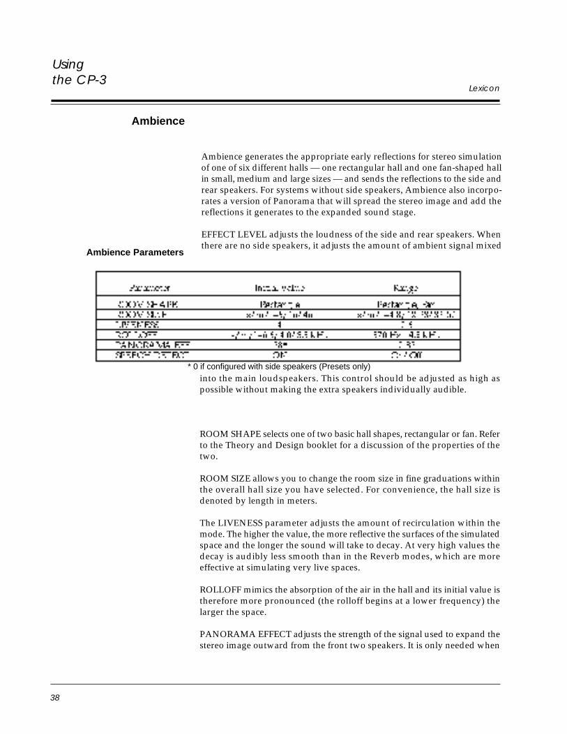
38
Usingthe CP-3
Lexicon
Ambience
Ambience generates the appropriate early reflections for stereo simulationof one of six different halls — one rectangular hall and one fan-shaped hallin small, medium and large sizes — and sends the reflections to the side andrear speakers. For systems without side speakers, Ambience also incorpo-rates a version of Panorama that will spread the stereo image and add thereflections it generates to the expanded sound stage.
EFFECT LEVEL adjusts the loudness of the side and rear speakers. Whenthere are no side speakers, it adjusts the amount of ambient signal mixed
Ambience Parameters
into the main loudspeakers. This control should be adjusted as high aspossible without making the extra speakers individually audible.
ROOM SHAPE selects one of two basic hall shapes, rectangular or fan. Referto the Theory and Design booklet for a discussion of the properties of thetwo.
ROOM SIZE allows you to change the room size in fine graduations withinthe overall hall size you have selected. For convenience, the hall size isdenoted by length in meters.
The LIVENESS parameter adjusts the amount of recirculation within themode. The higher the value, the more reflective the surfaces of the simulatedspace and the longer the sound will take to decay. At very high values thedecay is audibly less smooth than in the Reverb modes, which are moreeffective at simulating very live spaces.
ROLLOFF mimics the absorption of the air in the hall and its initial value istherefore more pronounced (the rolloff begins at a lower frequency) thelarger the space.
PANORAMA EFFECT adjusts the strength of the signal used to expand thestereo image outward from the front two speakers. It is only needed when
* 0 if configured with side speakers (Presets only)
39
Usingthe CP-3
CP-3 Digital Surround Processor
side speakers are absent. (If the system is configured without side speakers,the signal normally sent to the sides will be mixed into the front outputs.)
SPEECH DETECT The Speech Detection circuit distinguishes monauralspeech from other inputs. Essentially, this control turns down the effect tomake speech clearer. Whenever stereo signals are present, the right and leftinput channels are used independently as inputs to the ambience synthesis.If there is a strong monaural speaking voice present at the same time, thiscomponent of the input to the Ambience algorithm is reduced while thestereo component is increased.
If the input signal is pure monaural speech the input is almost entirelyattenuated. SPEECH DETECT is a real benefit to some popular music(where spoken voice, such as rap, occurs along with music), stereo televi-sion, and early stereo movies. Any stereo material which was not carefullymixed for Surround is a good candidate for playing through Ambience withSPEECH DETECT on.
In Ambience, MAIN MUTE mutes allows you to hear only the CP-3generated effects; EFFECTS MUTE allows you to hear the original, unproc-
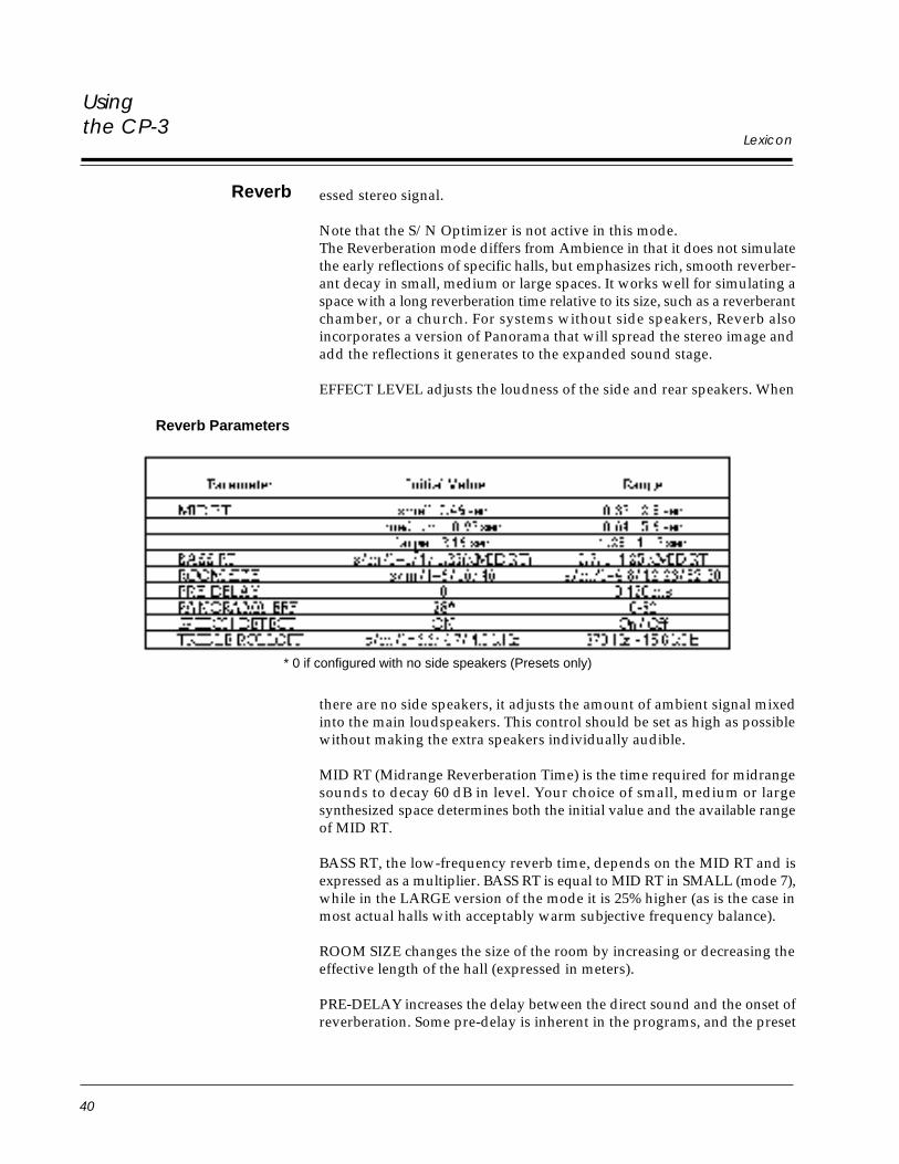
40
Usingthe CP-3
Lexicon
essed stereo signal.
Note that the S/N Optimizer is not active in this mode.The Reverberation mode differs from Ambience in that it does not simulatethe early reflections of specific halls, but emphasizes rich, smooth reverber-ant decay in small, medium or large spaces. It works well for simulating aspace with a long reverberation time relative to its size, such as a reverberantchamber, or a church. For systems without side speakers, Reverb alsoincorporates a version of Panorama that will spread the stereo image andadd the reflections it generates to the expanded sound stage.
EFFECT LEVEL adjusts the loudness of the side and rear speakers. When
Reverb
there are no side speakers, it adjusts the amount of ambient signal mixedinto the main loudspeakers. This control should be set as high as possiblewithout making the extra speakers individually audible.
MID RT (Midrange Reverberation Time) is the time required for midrangesounds to decay 60 dB in level. Your choice of small, medium or largesynthesized space determines both the initial value and the available rangeof MID RT.
BASS RT, the low-frequency reverb time, depends on the MID RT and isexpressed as a multiplier. BASS RT is equal to MID RT in SMALL (mode 7),while in the LARGE version of the mode it is 25% higher (as is the case inmost actual halls with acceptably warm subjective frequency balance).
ROOM SIZE changes the size of the room by increasing or decreasing theeffective length of the hall (expressed in meters).
PRE-DELAY increases the delay between the direct sound and the onset ofreverberation. Some pre-delay is inherent in the programs, and the preset
* 0 if configured with no side speakers (Presets only)
Reverb Parameters
41
Usingthe CP-3
CP-3 Digital Surround Processor
value of 0 is usually a good starting point. Increasing the pre-delay willmake the hall sound larger.
PANORAMA EFFECT adjusts the strength of the signal used to expand thestereo image outward from the front two speakers. Its initial value is zero,unless you have configured the CP-3 for no side loudspeakers.
SPEECH DETECT The Speech Detection circuit distinguishes monauralspeech from other inputs. Essentially, this control turns down the effect tomake speech clearer. Whenever stereo signals are present, the right and leftinput channels are used independently as inputs to the ambience synthesis.If there is a strong monaural speaking voice present at the same time, thiscomponent of the input is reduced while the stereo component is increased.
If the input signal is pure monaural speech the reverb effect is attenuated.SPEECH DETECT is a real benefit to some popular music (where spokenvoice, such as rap, occurs along with music), stereo television, and earlystereo movies.
TREBLE ROLLOFF, as in the Ambience mode, is preset to mimic airabsorption in actual spaces, being more pronounced in the larger ones.
In Reverb, MAIN MUTE mutes allows you to hear only the CP-3 generatedeffects; EFFECTS MUTE allows you to hear the original, unprocessed stereosignal.
Note that the S/N Optimizer is not active in this mode.
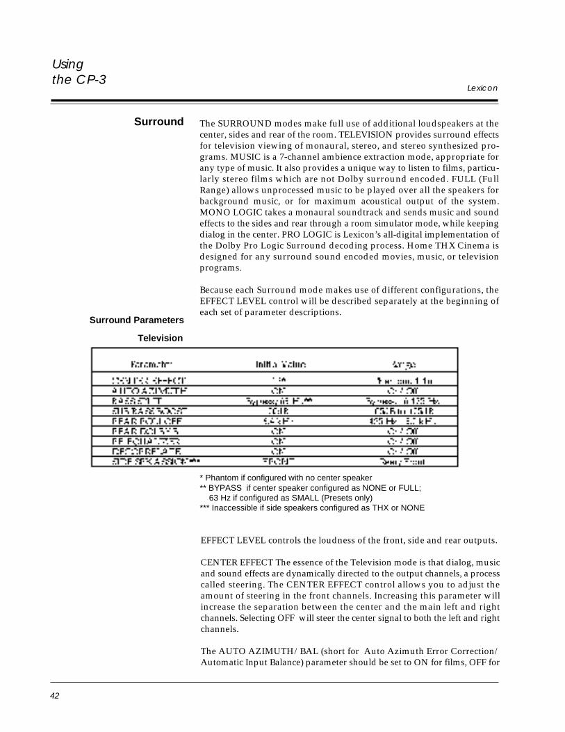
42
Usingthe CP-3
Lexicon
Surround The SURROUND modes make full use of additional loudspeakers at thecenter, sides and rear of the room. TELEVISION provides surround effectsfor television viewing of monaural, stereo, and stereo synthesized pro-grams. MUSIC is a 7-channel ambience extraction mode, appropriate forany type of music. It also provides a unique way to listen to films, particu-larly stereo films which are not Dolby surround encoded. FULL (FullRange) allows unprocessed music to be played over all the speakers forbackground music, or for maximum acoustical output of the system.MONO LOGIC takes a monaural soundtrack and sends music and soundeffects to the sides and rear through a room simulator mode, while keepingdialog in the center. PRO LOGIC is Lexicon’s all-digital implementation ofthe Dolby Pro Logic Surround decoding process. Home THX Cinema isdesigned for any surround sound encoded movies, music, or televisionprograms.
Because each Surround mode makes use of different configurations, theEFFECT LEVEL control will be described separately at the beginning ofeach set of parameter descriptions.
Television
Surround Parameters
EFFECT LEVEL controls the loudness of the front, side and rear outputs.
CENTER EFFECT The essence of the Television mode is that dialog, musicand sound effects are dynamically directed to the output channels, a processcalled steering. The CENTER EFFECT control allows you to adjust theamount of steering in the front channels. Increasing this parameter willincrease the separation between the center and the main left and rightchannels. Selecting OFF will steer the center signal to both the left and rightchannels.
The AUTO AZIMUTH/BAL (short for Auto Azimuth Error Correction/Automatic Input Balance) parameter should be set to ON for films, OFF for
* Phantom if configured with no center speaker** BYPASS if center speaker configured as NONE or FULL; 63 Hz if configured as SMALL (Presets only)*** Inaccessible if side speakers configured as THX or NONE
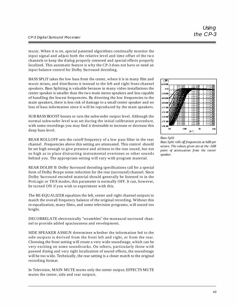
43
Usingthe CP-3
CP-3 Digital Surround Processor
music. When it is on, special patented algorithms continually monitor theinput signal and adjust both the relative level and time offset of the twochannels to keep the dialog properly centered and special effects properlylocalized. This automatic feature is why the CP-3 does not have or need aninput balance control for Dolby Surround decoding.
BASS SPLIT takes the low bass from the center, where it is in many film andmusic mixes, and distributes it instead to the left and right front-channelspeakers. Bass Splitting is valuable because in many video installations thecenter speaker is smaller than the two main stereo speakers and less capableof handling the lowest frequencies. By directing the low frequencies to themain speakers, there is less risk of damage to a small center speaker and noloss of bass information since it will be reproduced by the main speakers.
SUB BASS BOOST boosts or cuts the subwoofer output level. Although thenormal subwoofer level was set during the initial calibration procedure,with some recordings you may find it desireable to increase or decrease thisdeep bass level.
REAR ROLLOFF sets the cutoff frequency of a low pass filter in the rearchannel . Frequencies above this setting are attenuated. This control shouldbe set high enough to give presence and airiness to the rear sound, but notso high as to place distracting instrumental overtones or other soundsbehind you. The appropriate setting will vary with program material.
REAR DOLBY B Dolby Surround decoding specifications call for a specialform of Dolby B-type noise reduction for the rear (surround) channel. SinceDolby Surround encoded material should generally be listened to in theProLogic or THX modes, this parameter is normally OFF. It can, however,be turned ON if you wish to experiment with this.
The RE-EQUALIZER equalizes the left, center and right channel outputs tomatch the overall frequency balance of the original recording. Without thisre-equalization, many films, and some television programs, will sound toobright.
DECORRELATE electronically "scrambles" the monaural surround chan-nel to provide added spaciousness and envelopment.
SIDE SPEAKER ASSIGN determines whether the information fed to theside outputs is derived from the front left and right, or from the rear.Choosing the front setting will create a very wide soundstage, which can bevery exciting on some soundtracks. On others, particularly those withpanned dialog and very tight localization of sound effects, the soundstagewill be too wide. Technically, the rear setting is a closer match to the originalrecording format.
In Television, MAIN MUTE mutes only the center output; EFFECTS MUTEmutes the center, side and rear outputs.
Bass SplitBass Split rolls off frequencies at 6dB peroctave. The values given are at the -3dBpoint of attenuation from the centerspeaker.
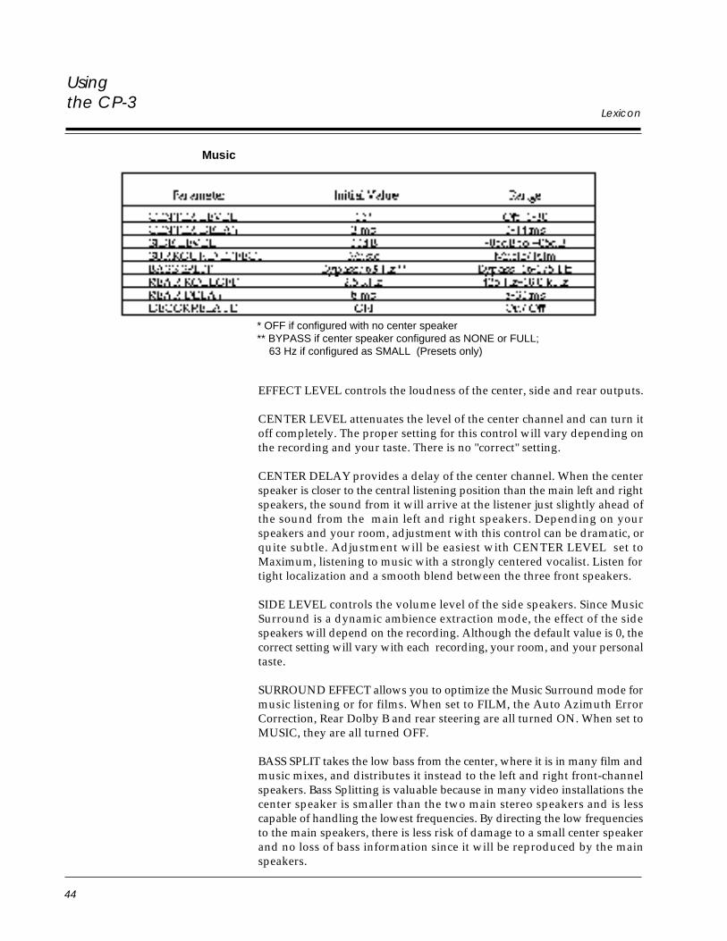
44
Usingthe CP-3
Lexicon
Music
* OFF if configured with no center speaker** BYPASS if center speaker configured as NONE or FULL; 63 Hz if configured as SMALL (Presets only)
EFFECT LEVEL controls the loudness of the center, side and rear outputs.
CENTER LEVEL attenuates the level of the center channel and can turn itoff completely. The proper setting for this control will vary depending onthe recording and your taste. There is no "correct" setting.
CENTER DELAY provides a delay of the center channel. When the centerspeaker is closer to the central listening position than the main left and rightspeakers, the sound from it will arrive at the listener just slightly ahead ofthe sound from the main left and right speakers. Depending on yourspeakers and your room, adjustment with this control can be dramatic, orquite subtle. Adjustment will be easiest with CENTER LEVEL set toMaximum, listening to music with a strongly centered vocalist. Listen fortight localization and a smooth blend between the three front speakers.
SIDE LEVEL controls the volume level of the side speakers. Since MusicSurround is a dynamic ambience extraction mode, the effect of the sidespeakers will depend on the recording. Although the default value is 0, thecorrect setting will vary with each recording, your room, and your personaltaste.
SURROUND EFFECT allows you to optimize the Music Surround mode formusic listening or for films. When set to FILM, the Auto Azimuth ErrorCorrection, Rear Dolby B and rear steering are all turned ON. When set toMUSIC, they are all turned OFF.
BASS SPLIT takes the low bass from the center, where it is in many film andmusic mixes, and distributes it instead to the left and right front-channelspeakers. Bass Splitting is valuable because in many video installations thecenter speaker is smaller than the two main stereo speakers and is lesscapable of handling the lowest frequencies. By directing the low frequenciesto the main speakers, there is less risk of damage to a small center speakerand no loss of bass information since it will be reproduced by the mainspeakers.
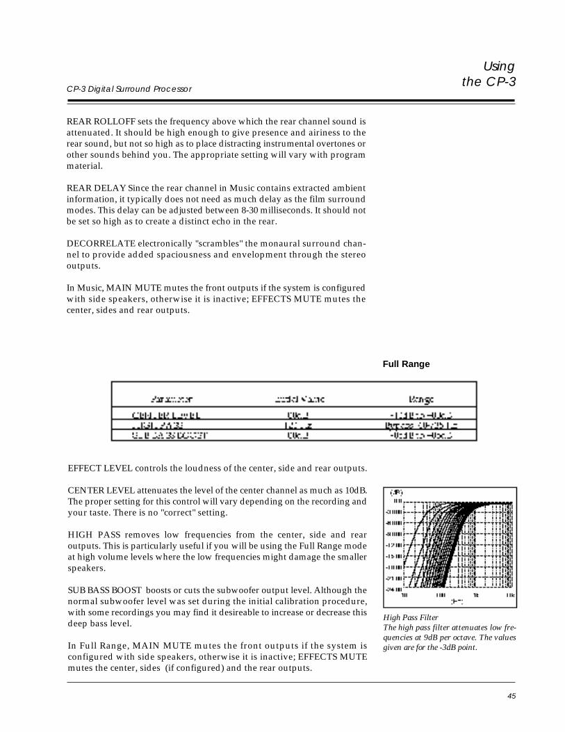
45
Usingthe CP-3
CP-3 Digital Surround Processor
REAR ROLLOFF sets the frequency above which the rear channel sound isattenuated. It should be high enough to give presence and airiness to therear sound, but not so high as to place distracting instrumental overtones orother sounds behind you. The appropriate setting will vary with programmaterial.
REAR DELAY Since the rear channel in Music contains extracted ambientinformation, it typically does not need as much delay as the film surroundmodes. This delay can be adjusted between 8-30 milliseconds. It should notbe set so high as to create a distinct echo in the rear.
DECORRELATE electronically "scrambles" the monaural surround chan-nel to provide added spaciousness and envelopment through the stereooutputs.
In Music, MAIN MUTE mutes the front outputs if the system is configuredwith side speakers, otherwise it is inactive; EFFECTS MUTE mutes thecenter, sides and rear outputs.
EFFECT LEVEL controls the loudness of the center, side and rear outputs.
CENTER LEVEL attenuates the level of the center channel as much as 10dB.The proper setting for this control will vary depending on the recording andyour taste. There is no "correct" setting.
HIGH PASS removes low frequencies from the center, side and rearoutputs. This is particularly useful if you will be using the Full Range modeat high volume levels where the low frequencies might damage the smallerspeakers.
SUB BASS BOOST boosts or cuts the subwoofer output level. Although thenormal subwoofer level was set during the initial calibration procedure,with some recordings you may find it desireable to increase or decrease thisdeep bass level.
In Full Range, MAIN MUTE mutes the front outputs if the system isconfigured with side speakers, otherwise it is inactive; EFFECTS MUTEmutes the center, sides (if configured) and the rear outputs.
High Pass FilterThe high pass filter attenuates low fre-quencies at 9dB per octave. The valuesgiven are for the -3dB point.
Full Range
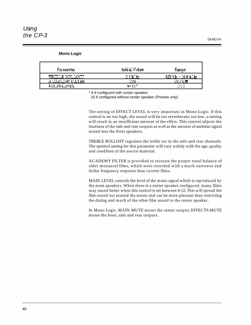
46
Usingthe CP-3
Lexicon
Mono Logic
* 6 if configured with center speaker; 15 if configured without center speaker (Presets only)
The setting of EFFECT LEVEL is very important in Mono Logic. If thiscontrol is set too high, the sound will be too reverberant; too low, a settingwill result in an insufficient amount of the effect. This control adjusts theloudness of the side and rear outputs as well as the amount of ambient signalmixed into the front speakers.
TREBLE ROLLOFF regulates the treble cut in the side and rear channels.The optimal setting for this parameter will vary widely with the age, qualityand condition of the source material.
ACADEMY FILTER is provided to recreate the proper tonal balance ofolder monaural films, which were recorded with a much narrower andduller frequency response than current films.
MAIN LEVEL controls the level of the mono signal which is reproduced bythe main speakers. When there is a center speaker configured, many filmsmay sound better when this control is set between 6-12. This will spread thefilm sound out around the screen and can be more pleasant than restrictingthe dialog and much of the other film sound to the center speaker.
In Mono Logic, MAIN MUTE mutes the center output; EFFECTS MUTEmutes the front, side and rear outputs.
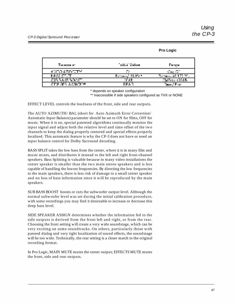
47
Usingthe CP-3
CP-3 Digital Surround Processor
Pro Logic
* depends on speaker configuration** Inaccessible if side speakers configured as THX or NONE
EFFECT LEVEL controls the loudness of the front, side and rear outputs.
The AUTO AZIMUTH/BAL (short for Auto Azimuth Error Correction/Automatic Input Balance) parameter should be set to ON for films, OFF formusic. When it is on, special patented algorithms continually monitor theinput signal and adjust both the relative level and time offset of the twochannels to keep the dialog properly centered and special effects properlylocalized. This automatic feature is why the CP-3 does not have or need aninput balance control for Dolby Surround decoding.
BASS SPLIT takes the low bass from the center, where it is in many film andmusic mixes, and distributes it instead to the left and right front-channelspeakers. Bass Splitting is valuable because in many video installations thecenter speaker is smaller than the two main stereo speakers and is lesscapable of handling the lowest frequencies. By directing the low frequenciesto the main speakers, there is less risk of damage to a small center speakerand no loss of bass information since it will be reproduced by the mainspeakers.
SUB BASS BOOST boosts or cuts the subwoofer output level. Although thenormal subwoofer level was set during the initial calibration procedure,with some recordings you may find it desireable to increase or decrease thisdeep bass level.
SIDE SPEAKER ASSIGN determines whether the information fed to theside outputs is derived from the front left and right, or from the rear.Choosing the front setting will create a very wide soundstage, which can bevery exciting on some soundtracks. On others, particularly those withpanned dialog and very tight localization of sound effects, the soundstagewill be too wide. Technically, the rear setting is a closer match to the originalrecording format.
In Pro Logic, MAIN MUTE mutes the center output; EFFECTS MUTE mutesthe front, side and rear outputs.
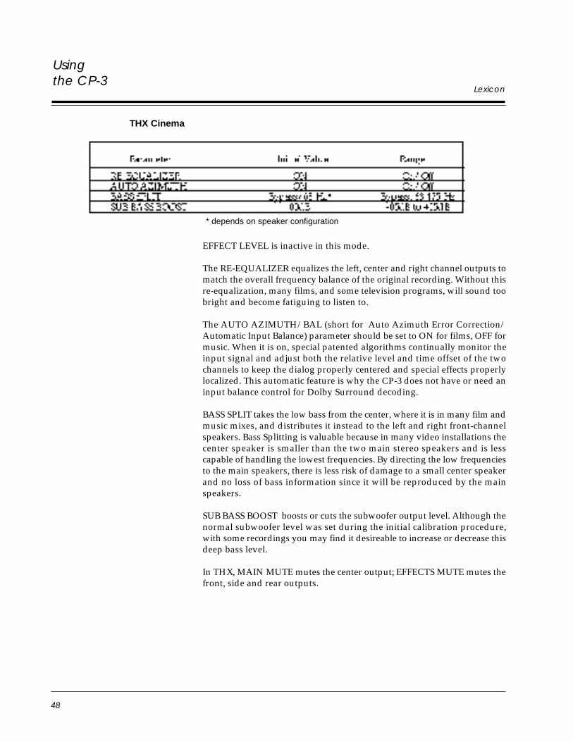
48
Usingthe CP-3
Lexicon
* depends on speaker configuration
THX Cinema
EFFECT LEVEL is inactive in this mode.
The RE-EQUALIZER equalizes the left, center and right channel outputs tomatch the overall frequency balance of the original recording. Without thisre-equalization, many films, and some television programs, will sound toobright and become fatiguing to listen to.
The AUTO AZIMUTH/BAL (short for Auto Azimuth Error Correction/Automatic Input Balance) parameter should be set to ON for films, OFF formusic. When it is on, special patented algorithms continually monitor theinput signal and adjust both the relative level and time offset of the twochannels to keep the dialog properly centered and special effects properlylocalized. This automatic feature is why the CP-3 does not have or need aninput balance control for Dolby Surround decoding.
BASS SPLIT takes the low bass from the center, where it is in many film andmusic mixes, and distributes it instead to the left and right front-channelspeakers. Bass Splitting is valuable because in many video installations thecenter speaker is smaller than the two main stereo speakers and is lesscapable of handling the lowest frequencies. By directing the low frequenciesto the main speakers, there is less risk of damage to a small center speakerand no loss of bass information since it will be reproduced by the mainspeakers.
SUB BASS BOOST boosts or cuts the subwoofer output level. Although thenormal subwoofer level was set during the initial calibration procedure,with some recordings you may find it desireable to increase or decrease thisdeep bass level.
In THX, MAIN MUTE mutes the center output; EFFECTS MUTE mutes thefront, side and rear outputs.
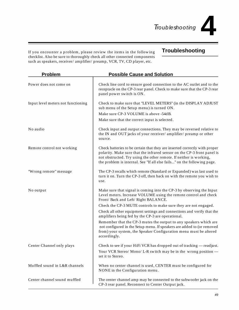
49
CP-3 Digital Surround ProcessorTroubleshooting
Troubleshooting
4Troubleshooting
If you encounter a problem, please review the items in the followingchecklist. Also be sure to thoroughly check all other connected componentssuch as speakers, receiver/amplifier/preamp, VCR, TV, CD player, etc.
Problem Possible Cause and Solution
Power does not come on Check line cord to ensure good connection to the AC outlet and to thereceptacle on the CP-3 rear panel. Check to make sure that the CP-3 rearpanel power switch is ON.
Input level meters not functioning Check to make sure that "LEVEL METERS" (in the DISPLAY ADJUSTsub menu of the Setup menu) is turned ON.
Make sure CP-3 VOLUME is above -54dB.
Make sure that the correct input is selected.
No audio Check input and output connections. They may be reversed relative tothe IN and OUT jacks of your receiver/amplifier/preamp or othersource.
Remote control not working Check batteries to be certain that they are inserted correctly with properpolarity. Make sure that the infrared sensor on the CP-3 front panel isnot obstructed. Try using the other remote. If neither is working,the problem is internal. See "If all else fails..." on the following page.
"Wrong remote" message The CP-3 recalls which remote (Standard or Expanded) was last used toturn it on. Turn the CP-3 off, then back on with the remote you wish touse.
No output Make sure that signal is coming into the CP-3 by observing the InputLevel meters. Increase VOLUME using the remote control and checkFront/Back and Left/Right BALANCE.
Check the CP-3 MUTE controls to make sure they are not engaged.
Check all other equipment settings and connections and verify that theamplifiers being fed by the CP-3 are operational.
Remember that the CP-3 mutes the output to any speakers which are not configured in the Setup menu. If speakers are added to (or removedfrom) your system, the Speaker Configuration menu must be alteredaccordingly.
Center Channel only plays Check to see if your HiFi VCR has dropped out of tracking — readjust.
Your VCR Stereo/Mono/L-R switch may be in the wrong position —set it to Stereo.
Muffled sound in L&R channels When no center channel is used, CENTER must be configured forNONE in the Configuration menu.
Center channel sound muffled The center channel amp may be connected to the subwoofer jack on theCP-3 rear panel. Reconnect to Center Output jack.
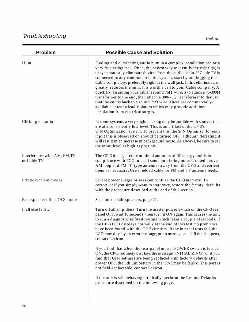
50
LexiconTroubleshooting
Problem Possible Cause and Solution
Hum Finding and eliminating audio hum in a complex installation can be avery frustrating task. Often, the easiest way to identify the culprit(s) isto systematically eliminate devices from the audio chain. If Cable TV isconnected to any component in the system, start by unplugging theCable completely, preferably right at the wall jack. If this eliminates, orgreatly reduces the hum, it is worth a call to your Cable company. Aquick fix, assuming your cable is round 75Ω wire, is to attach a 75-300Ωtransformer to the end, then attach a 300-75Ω transformer to that, sothat the end is back to a round 75Ω wire. There are commercially-available antenna lead isolators which may provide additional insulation from electrical surges.
Clicking in audio In some systems a very slight clicking may be audible with sources thatare at a consistently low level. This is an artifact of the CP-3'sS/N Optimization system. To prevent this, the S/N Optimizer for eachinput this is observed on should be turned OFF, although defeating itwill result in an increase in background noise. As always, be sure to setthe input level as high as possible.
Interference with AM, FM,TV The CP-3 does generate minimal amounts of RF energy and is inor Cable TV compliance with FCC rules. If some interfering noise is noted, move
AM loop and FM "T" type antennas away from the CP-3 and reorientthem as necessary. Use shielded cable for FM and TV antenna feeds.
Erratic recall of modes Severe power surges or sags can confuse the CP-3 memory. Tocorrect, or if you simply want to start over, restore the factory defaultswith the procedure described at the end of this section.
Rear speaker off in THX mode See note on side speakers, page 21.
If all else fails… Turn off all amplifiers. Turn the master power switch on the CP-3 rearpanel OFF, wait 10 seconds, then turn it ON again. This causes the unitto run a diagnostic self-test routine which takes a couple of seconds. Ifthe CP-3 LCD displays normally at the end of this test, no problemshave been found with the CP-3 circuitry. If the internal tests fail, theLCD may display an error message, or no message at all. If this happens,contact Lexicon.
If you find that when the rear-panel master POWER switch is turnedON, the CP-3 routinely displays the message "INITIALIZING", or if youfind that User settings are being replaced with factory defaults afterpower OFF, the lithium battery in the CP-3 may be faulty. This part isnot field-replaceable, contact Lexicon.
If the unit is still behaving erratically, perform the Restore Defaultsprocedure described on the following page.
51
CP-3 Digital Surround ProcessorTroubleshooting
Routine MaintenanceOther than occasional replacement of the batteries in the remote controlunits, the CP-3 requires minimal maintenance. Use a soft, lint-free clothslightly dampened with warm water and a mild detergent to clean theexterior surfaces of the unit.
Do not use alcohol, benzene or acetone-based cleanersor any strong commercial cleaners.
Avoid using any abrasive materials such as steel wool or metal polish. If theunit is exposed to a dusty environment, a vacuum or low-pressure blowermay be used to remove dust from the CP-3 exterior.
Restoring DefaultsIf severe power surges or sags cause problems with CP-3 memory storage,or you simply want to start with a clean slate, you can restore factory presetsinto the User registers with the following procedure.
This will erase any programs you have stored in the User registers,as well as all setup and calibration values.
Note any settings you want to re-use before proceeding.
With the Expanded Remote control, turn the CP-3 OFF. Turn the unit backON and press the SETUP button within two seconds. (Make sure you do notblock the infrared receiver on the CP-3 front panel.) Continue holding downSETUP until the display reads:
* RESTORE MODE *SETUP TO EXIT
(If you want to resume normal operation without restoring all defaults, thisis your last chance. Release SETUP and press SETUP again to resumenormal operation.)
To restore defaults, release SETUP and press STORE to clear and reloadUser registers, and to restore all factory settings of Volume, Balance,Contrast, Configuration, etc.
The display will flash an INITIALIZING message then read:
* RESTORED ALL *SETUP TO EXIT
Press SETUP to resume normal operation.
All of the adjustable parameters in the CP-3 have now been reset to thevalues assigned when it cleared final Quality Control at the factory. Usingthe values notated on the Installation Worksheet at the end of this manual,follow the initial setup procedure starting on Page 18.
If you cannot solve functional problems through these procedures, consultyour dealer or Lexicon/Customer Service Department.
DO NOT, UNDER ANY CIRCUMSTANCES, OPEN THE UNIT.DOING SO WILL VOID YOUR WARRANTY,
AND MODIFICATIONS MAY RENDER THE UNIT UNSERVICEABLE.
53
CP-3 Digital Surround Processor
InstallationDocumentation5Installation
Documentation
InstallationDocumentation
This section is provided for the documentation of values set during systemsetup and calibration. The Setup menu selections are reproduced here foryour convenience when filling out the worksheet.
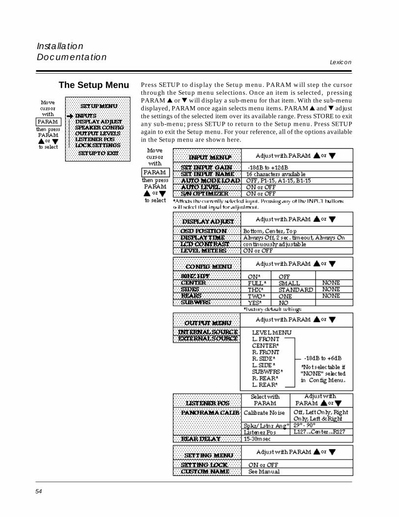
54
Lexicon
InstallationDocumentation
Press SETUP to display the Setup menu. PARAM will step the cursorthrough the Setup menu selections. Once an item is selected, pressingPARAM or will display a sub-menu for that item. With the sub-menudisplayed, PARAM once again selects menu items. PARAM and adjustthe settings of the selected item over its available range. Press STORE to exitany sub-menu; press SETUP to return to the Setup menu. Press SETUPagain to exit the Setup menu. For your reference, all of the options availablein the Setup menu are shown here.
The Setup Menu
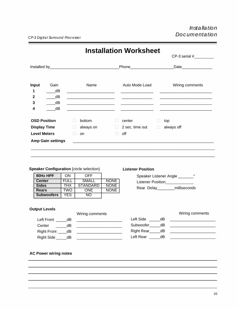
55
CP-3 Digital Surround Processor
InstallationDocumentation
Installation WorksheetCP-3 serial #_________
Installed by________________________________Phone____________________Date______________
AC Power wiring notes
Input Gain Name Auto Mode Load Wiring comments
1 ____dB ______________________ _______________ ________________________
2 ____dB ______________________ ______________ ________________________
3 ____dB ______________________ _______________ ________________________
4 ____dB ______________________ _______________ ________________________
OSD Position bottom center top
Display Time always on 2 sec. time out always off
Level Meters on off
Amp Gain settings _________________________________________________________________
_____________________________________________________________________________________
_____________________________________________________________________________________
Wiring comments
Left Side _____dB _____________________
Subwoofer_____dB _____________________
Right Rear_____dB _____________________
Left Rear _____dB _____________________
Output LevelsWiring comments
Left Front _____dB _____________________
Center _____dB _____________________
Right Front ____dB _____________________
Right Side _____dB _____________________
Listener Position
Speaker Listener Angle _______°
Listener Position_____________
Rear Delay________milliseconds
Speaker Configuration [circle selection)
80Hz HPF ON OFFCenter FULL SMALL NONESides THX STANDARD NONERears TWO ONE NONESubwoofers YES NO

57
CP-3 Digital Surround Processor Specifications6Specifications
Inputs: Audio: 4 stereo pairsMinimum Input Level: 300 mVrms for maximum output
35 mVrms for Dolby levelInput Impedance: 100 kΩ in parallel with 100pf
Video: 3 composite, NTSC M standardInput Sensitivity and Impedance: 1V p-p, 75Ω
Outputs: Audio: 8 outputs (Left, Right, Center, Subwoofer, 2 Side, 2 Rear)Maximum Output Level: 6 VrmsOutput Impedance: 500 Ω
Video: 1 composite, NTSC M standardOutput Level and Impedance: 1V p-p, 75Ω
Frequency Response: Unprocessed channels: 10 Hz - 100 kHz, +1, -3dB, Ref. 1 kHzProcessed channels: 10 Hz - 18 kHz, +1, -3dB, Ref. 1 kHz
Subwoofer: 10 Hz-80 Hz, +1, -6dB, Ref. 31.5Hz, 24dB/octave rolloff
THD: All channels: Less than .025% @1 kHz, max levelSubwoofer: Less than .025% @10-100 Hz, max level
Signal to Noise Ratio: 90dB minimum, A-weighted, Ref. 1 kHz max level
Power Requirements: 120 VAC +10% 50-60 Hz 35W100/220/240 VAC versions available3-pin IEC detachable power cord provided
Dimensions: 17.5"W x 14.5"D x 3.7"H (445 x 368 x 94mm)Brackets supplied for rack mounting: conforms to 19" standard, 2U high(3.5"H without feet)
Weight: 18 lbs. 4oz. (8.3kg)
Environment: Operating Temperature: 32° to 95°F (0° to 35°C)Storage Temperature: -22° to 167°F (-30° to 75°)Humidity: 95% maximum without condensation
Remote Controls: 2 hand-held, battery-powered remote control units providedwith each CP-3; each uses 2 AA batteries (provided):1 18-button "Standard" remote1 36-button "Expanded" remote
Specifications subject to change without notice.
Specifications

Lexicon Part #070-08342 Rev 1 Printed in the United States of America
Lexicon, Inc.3 Oak ParkBedford, MA 01730Tel 781-280-0300Fax 781-280-0490