owner’s manual - bathroom · pdf filefax: 937-497-3183 web site: ... owner’s...
TRANSCRIPT
WARNING: Improper installation, adjustment, alteration, service or mainte-nance can cause injury or property damage. Refer to this manual.For assistance or additional information, contact a qualified in-staller, service agency, or the gas supplier.
FOR YOUR SAFETYDo not store or use gasoline or other flammable vapors and liquid inthe vicinity of this or any other appliance.
FOR YOUR SAFETYIf you smell gas:
1. Open windows.2. Don’t touch electrical switches.3. Extinguish any open flame.4. Immediately call your gas supplier.
Owner’s Manual
For model N400 - a 4.5 cu. ft., 2-way or 3-way, refrigerator.For model N500 - a 5.5 cu. ft., 2-way or 3-way, refrigerator.For model N510 - a 5.5 cu. ft., 2-way or 3-way, refrigerator.
The model numbers of 3-way refrigerators include “.3”. The model numbers of 2-way mod-els do not.
NORCOLD, Inc.P.O. Box 4248Sidney, OH 45365-4248
Part No. 622266C (6-02)
English
French
Norcold Customer Support Dept.Telephone: 800-543-1219
Fax: 937-497-3183Web Site: www.norcold.com
Owner’s Manual 2
Table of Contents
Gas Absorption 3 Year Limited Warranty Policy ......................... 2Gas Absorption Warranty Information ........................................ 3Gas Absorption Warranty Questions .......................................... 3Safety Awareness ....................................................................... 4Safety Instuctions ....................................................................... 4About Your Refrigerator .............................................................. 4
Storage volume ................................................................... 4Leveling ............................................................................... 4Food compartment .............................................................. 4Flip-up shelf ........................................................................ 4Door bins ............................................................................. 5Freezer compartment .......................................................... 5Operation during travel ........................................................ 5Door latch for travel and storage ......................................... 5Temperature control system (N510 models) ..................... 5
Operating the Refrigerator Controls (N400 models) ................. 5Control Panel ...................................................................... 5Ignition - propane gas operation ........................................ 6Do a test of the gas safety valve .......................................... 6Start up - AC operation ......................................................... 6Start up - DC operation (N400.3 models) ........................... 6Shut down ........................................................................... 6
Operating the Refrigerator Controls (N500 models) ................. 6Control Panel ...................................................................... 6Ignition - propane gas operation ........................................ 7Do a test of the gas safety valve .......................................... 7Start up - AC operation ......................................................... 7Start up - DC operation (N500.3 models) ........................... 7Shut down ........................................................................... 7
Operating the Refrigerator Controls (N510 models) ................. 7Control Panel ...................................................................... 7Automatic mode operation .................................................. 8Removing the air from the propane gas supply lines ........ 8Set the controls to automatic mode operation ................... 8Set the controls to manual mode operation ....................... 9Backup operating system ................................................... 9
DC Operation Precautions (N400.3, N500.3, andN510.3 models) ................................................................ 10
DC Operation Guidelines (N400.3, N500.3, andN510.3 models) ................................................................ 10
Effects of High Altitude on Propane Gas Operation ................. 10Refrigerator Care Checklist ..................................................... 10Defrosting ................................................................................. 10
N510 Models only .............................................................. 11Cleaning .................................................................................... 11Door Sealing ............................................................................. 11Refrigerator Maintenance Checklist ......................................... 11Refrigerator Storage ................................................................. 12Refrigerator Maintenance ......................................................... 12
Gas flame appearance ..................................................... 12Remove and clean the burner orifice ............................... 12
Remove the Refrigerator .......................................................... 13Reinstall the Refrigerator ......................................................... 13Replacement Parts .................................................................. 13Wiring Pictorial (N400 models) ................................................ 14Wiring Diagram (N400 models) .............................................. 14Wiring Pictorial (N500 models) ................................................ 14Wiring Diagram (N500 models) .............................................. 14Wiring Pictorial (N510 models) ................................................ 14Wiring Diagram (N510 models) .............................................. 14Fault Codes (N510 models) .................................................... 15
Norcold • P.O. Box 4248 • Sidney, OH • USA • 45365-4248
Provided it is properly installed, properly maintained and placedunder normal service and use, Norcold, Inc. warrants itsrefrigeration equipment to be free from defects in material andworkmanship for three years with respect to the equipment’scomponent parts, and for two years with respect to the labor torepair or replace such parts, commencing from the original dateof purchase.
Limitations of warranty
1. This Warranty applies only to Norcold gas absorptionrefrigerator operating equipment. This Warranty does notextend to glassware, electric light bulbs, and replaceablefuses.
2. This warranty does not apply to parts and assemblies thathave been subjected to misuse, improper installation,improper or abnormal service, transit damage, recharging ofthe cooling system, accident, fire, improper repair, tamperingor abuse.
3. Irrespective of the nature of the warranty protection offered orclaimed, the period of warranty shall in no case extendbeyond three years for component parts and two years for thelabor to repair or replace such parts, commencing from theoriginal date of purchase of the new equipment.
4. In order to obtain the remedy of repair and replacement, therefrigerator must be brought to any Norcold Service Center forwarranty service. The end consumer is responsible for allexpenses resulting from any remote service call if therefrigerator cannot be brought into the Norcold service center.
5. It is the responsibility of the end consumer to have mainte-nance performed upon the warranted equipment one timeduring the second year or before the beginning of the thirdyear after original purchase. Such maintenance is required tomaintain this warranty in effect and failure to perform suchmaintenance will void the remainder of the warranty. Re-quired maintenance during the second year or before thethird year after purchase is cleaning and checking of thefollowing: Burner, Flue, Spiral Baffle, Roof Cap Screen, andControl Board Sequence.
LIMITATION OF REMEDY
1. THE RESPONSIBILITY OF NORCOLD UNDER THIS OR ANYWARRANTY IS LIMITED TO THE REPAIR OR REPLACEMENT(AT NORCOLD’S OPTION) OF THE DEFECTIVE PART ORASSEMBLY.
NORCOLD - Gas Absorption 3 Year LimitedWarranty Policy
Owner’s Manual 3
Gas Absorption Warranty Information
2. IN NO EVENT AND UNDER NO CIRCUMSTANCES SHALLNORCOLD BE RESPONSIBLE UNDER THIS LIMITED WAR-RANTY FOR ANY OTHER CHARGE WHATSOEVER, INCLUDINGBUT NOT LIMITED TO CHARGES OR CLAIMS FOR LABOR,LOST BUSINESS, LOST TIME, LOST PROFITS, LOSS OF USE,OR ANY KIND OF INCIDENTAL OR CONSEQUENTIAL DAM-AGES, HOWEVER DENOMINATED OR DESCRIBED. THEREMEDY UNDER THIS WARRANTY IS LIMITED TO REPLACE-MENT OR REPAIR.
3. SOME STATES DO NOT ALLOW THE EXCLUSION ORLIMITATION OF INCIDENTAL OR CONSEQUENTIAL DAMAGES,SO THE ABOVE EXCLUSION MAY NOT APPLY TO YOU.
DISCLAIMER OF OTHER WARRANTIES
THIS WARRANTY IS EXPRESSLY IN LIEU OF ALL OTHERWARRANTIES EITHER EXPRESSED OR IMPLIED. ALL OTHERWARRANTIES, EXPRESSED OR IMPLIED, INCLUDING ANYWARRANTY OF MERCHANTABILITY OR FITNESS FOR A PAR-TICULAR PURPOSE, ARE HEREBY DISCLAIMED AND EX-CLUDED.
Legal rights
This warranty gives you specific legal rights, and you may haveother legal rights, which vary from state to state.
Your refrigerator is made to provide the ultimate in coolingsatisfaction and will serve you reliably in the years to come.Norcold refrigerators are the only RV refrigerators made in theUnited States and offer a standard limited three-year warranty.Norcold also offers an additional warranty coverage plan whichextends the standard limited three-year warranty. To activateyour three-year limited warranty and to receive an invitation toparticipate in the extended warranty plan, complete and mail thewarranty registration supplied.
Help us to help you.
Write the model number and serial number below for futurereference. These numbers are on the serial plate in therefrigerator. The serial plate is located in the fresh foodcompartment on the top right hand side. Use these numberswhen receiving service or in any correspondence concerningyour refrigerator.
Model number ___________ Serial number ___________
If a problem occurs with your refrigerator, contact any of theservice centers throughout the United States and Canada. Tofind an authorized Norcold Service Center near you, pleasetelephone the Norcold Customer Support Dept. at 800-543-1219 (option-1) or visit our web site at www.norcold.com.
Norcold is committed to providing products that are in harmonywith the environment. Your Norcold refrigerator meets allenvironmental safety standards.
This warranty is the only warranty for your Norcold refrigerator.There are no other express warranties. The only uses for thisproduct are described in this manual. Part or model specifica-tions are subject to change without notice.
What does this warranty cover?This warranty covers labor and U.P.S. ground transportationcosts incurred in removing and reinstalling the refrigeratorwhen necessary to replace a defective part and any partsreplaced under warranty (including cooling units).
What is not covered by this warranty?- Travel expenses for bringing the refrigerator to an autho-
rized Norcold Service Center for warranty coverage.- Additional costs caused by the inability to bring the
refrigerator to an authorized Norcold Service Center.- Defects which are caused by transit damage, misuse,
neglect, or accident.- Manufacturing defects found at the time of purchase, parts
replaced under warranty, and associated labor, which theoriginal consumer-purchaser do not communicate toNorcold within 30 days.
- Labor, performed without need for parts replacements,which the original consumer-purchaser does not commu-nicate to Norcold within 30 days.
- Defects in glassware, electric light bulbs, or replacementfuses.
- Defects caused by improper installation, maintenance, oradjustment.
- Normal maintenance of this refrigerator as described in thismanual.
- Defects caused by the improper use of parts or parts notmanufactured or supplied by Norcold for repairs or replace-ments to the refrigerator.
Norcold will not be liable for any incidental or consequentialloss or damage, due directly or indirectly to the use of thisproduct. Some states do not allow the exclusion or limitationof incidental or consequential damages, so the above maynot apply to you.
How long does this warranty last?This warranty is effective for a period of two years from date ofpurchase or for a period of three years from date of puchase ifthe required maintenance is done.
What will Norcold do?Norcold will provide free service and replacement of defectiveparts, at no charge, at all authorized Norcold Service Centers.Norcold has the option of replacing the defective parts or theentire refrigerator. If the refrigerator is replaced, Norcold isnot responsible for replacing dealer installed options.
How do you get service?Bring the refrigerator to any authorized Norcold Service Centerand: - Show proof that the defective item is within warranty
coverage.- Show proof that required maintenance has been performed
if applicable. Required maintenance during the secondyear or before the third year after purchase is cleaning andchecking of the Burner, Flue, Spiral Baffle, Roof CapScreen, and Control Board Sequence.
If you are unable to bring the refrigerator to an authorizedNorcold Service Center:
- Send a written notice of the defect to Norcold.- Norcold will promptly advise you how to obtain warranty
service.
What rights do you have?This warranty gives you specific legal rights. You may alsohave other rights which vary from state to state.
Gas Absorption Warranty Questions
Owner’s Manual 4
About Your Refrigerator
- The refrigerator cooling system is under pressure. Donot try to repair or to recharge a defective coolingsystem. The cooling system contains sodium chro-mate. The breathing of certain chromium compoundscan cause cancer. The cooling system contents cancause severe skin and eye burns, and can ignite andburn with an intense flame. Do not bend, drop, weld,move, drill, puncture, or hit the cooling system.
- At regular intervals, make sure that the refrigerator fluethe burner, the vent areas, and the ventilation airpathway between the vents are completely free fromany flammable material or blockage. After a period ofstorage, it is especially important to check these areasfor any flammable material or blockage caused byanimals.
CAUTION:
- The rear of the refrigerator has sharp edges andcorners. To prevent cuts or abrasions when workingon the refrigerator, be careful and wear cut resistantgloves.
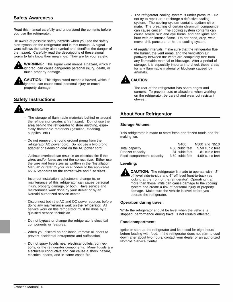
Storage Volume:
This refrigerator is made to store fresh and frozen foods and formaking ice.
N400 N500 and N510Total capacity 4.50 cubic feet 5.50 cubic feetFreezer capacity .81 cubic feet .81 cubic feetFood compartment capacity 3.69 cubic feet 4.69 cubic feet
Leveling:
CAUTION: The refrigerator is made to operate within 3°off level side-to-side and 6° off level front-to-back (aslooking at the front of the refrigerator). Operating it atmore than these limits can cause damage to the coolingsystem and create a risk of personal injury or propertydamage. Make sure the vehicle is level before youoperate the refrigerator.
Operation during travel:
While the refrigerator should be level when the vehicle isstopped, performance during travel is not usually effected.
Food compartment:
Ignite or start up the refrigerator and let it cool for eight hoursbefore loading with food. If the refrigerator does not start to cooldown after about two hours, contact your dealer or an authorizedNorcold Service Center.
WARNING:
- The storage of flammable materials behind or aroundthe refrigerator creates a fire hazard. Do not use thearea behind the refrigerator to store anything, espe-cially flammable materials (gasoline, cleaningsupplies, etc.)
- Do not remove the round ground prong from therefrigerator AC power cord. Do not use a two prongadapter or extension cord on the AC power cord.
- A circuit overload can result in an electrical fire if thewires and/or fuses are not the correct size. Either usethe wire and fuse sizes as writtten in the “InstallationManual” or refer to your local codes or the applicableRVIA Standards for the correct wire and fuse sizes.
- Incorrect installation, adjustment, change to, ormaintenance of this refrigerator can cause personalinjury, property damage, or both. Have service andmaintenance work done by your dealer or by anNorcold authorized service center.
- Disconnect both the AC and DC power sources beforedoing any maintenance work on the refrigerator. Allservice work on this refrigerator must be done by aqualified service technician.
- Do not bypass or change the refrigerator’s electricalcomponents or features.
- When you discard an appliance, remove all doors toprevent accidental entrapment and suffocation.
- Do not spray liquids near electrical outlets, connec-tions, or the refrigerator components. Many liquids areelectrically conductive and can cause a shock hazard,electrical shorts, and in some cases fire.
Safety Instructions
Read this manual carefully and understand the contents beforeyou use the refrigerator.
Be aware of possible safety hazards when you see the safetyalert symbol on the refrigerator and in this manual. A signalword follows the safety alert symbol and identifies the danger ofthe hazard. Carefully read the descriptions of these signalwords to fully know their meanings. They are for your safety.
WARNING: This signal word means a hazard, which ifignored, can cause dangerous personal injury, death, ormuch property damage.
CAUTION: This signal word means a hazard, which ifignored, can cause small personal injury or muchproperty damage.
Safety Awareness
Owner’s Manual 5
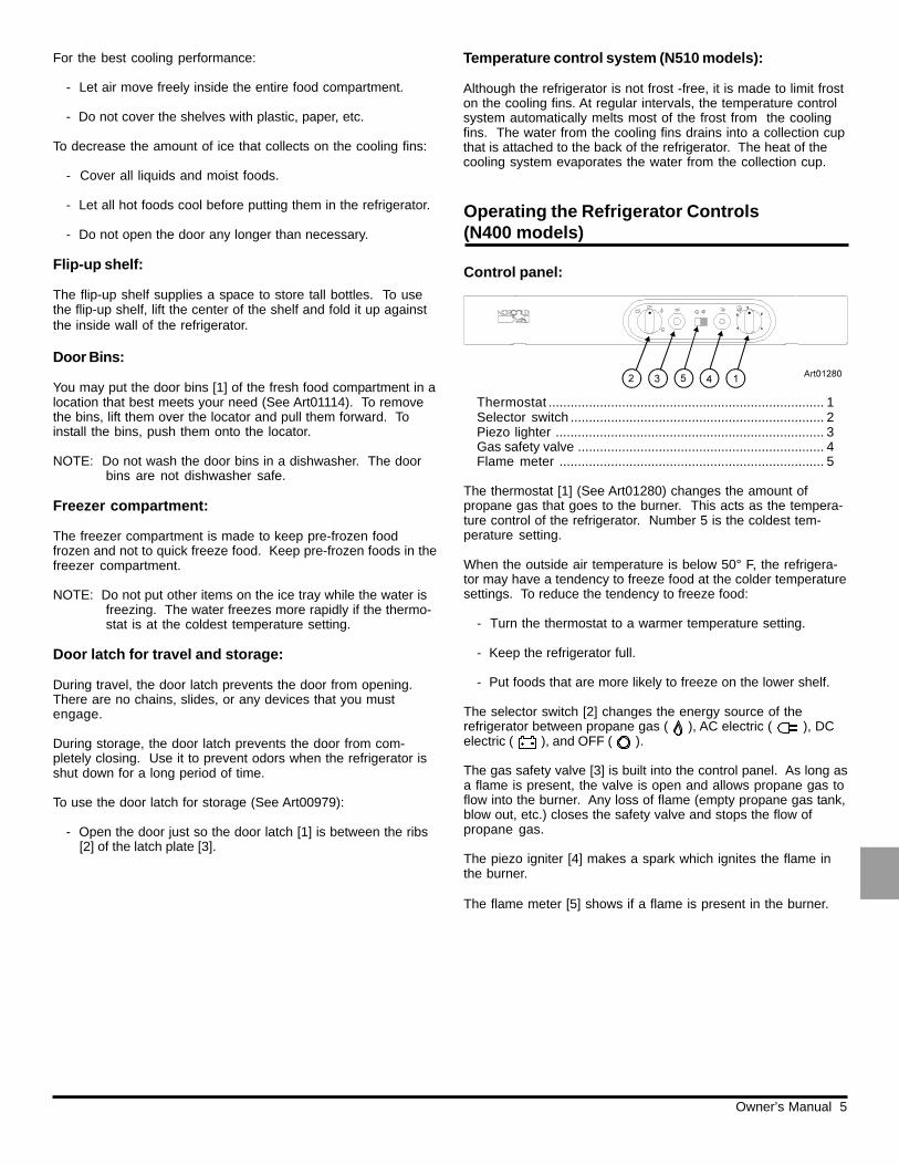
Control panel:
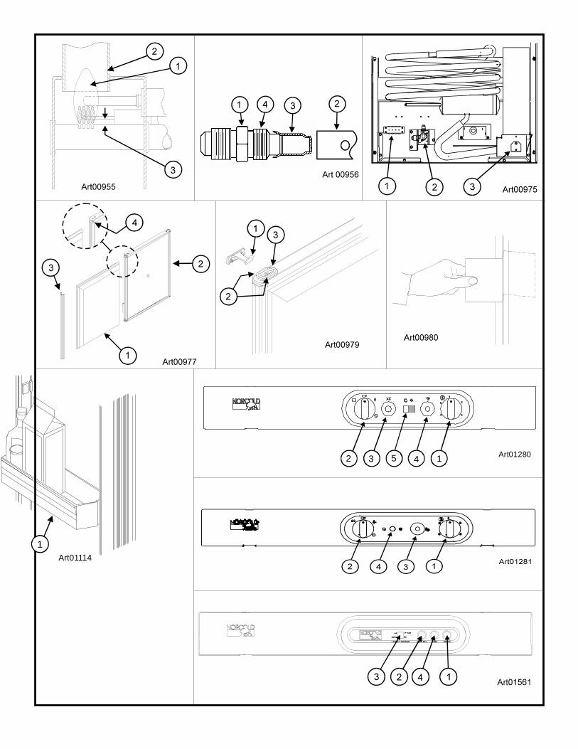
Thermostat ........................................................................... 1Selector switch ..................................................................... 2Piezo lighter ......................................................................... 3Gas safety valve ................................................................... 4Flame meter ........................................................................ 5
The thermostat [1] (See Art01280) changes the amount ofpropane gas that goes to the burner. This acts as the tempera-ture control of the refrigerator. Number 5 is the coldest tem-perature setting.
When the outside air temperature is below 50° F, the refrigera-tor may have a tendency to freeze food at the colder temperaturesettings. To reduce the tendency to freeze food:
- Turn the thermostat to a warmer temperature setting.
- Keep the refrigerator full.
- Put foods that are more likely to freeze on the lower shelf.
The selector switch [2] changes the energy source of therefrigerator between propane gas ( ), AC electric ( ), DCelectric ( ), and OFF ( ).
The gas safety valve [3] is built into the control panel. As long asa flame is present, the valve is open and allows propane gas toflow into the burner. Any loss of flame (empty propane gas tank,blow out, etc.) closes the safety valve and stops the flow ofpropane gas.
The piezo igniter [4] makes a spark which ignites the flame inthe burner.
The flame meter [5] shows if a flame is present in the burner.
Operating the Refrigerator Controls(N400 models)
For the best cooling performance:
- Let air move freely inside the entire food compartment.
- Do not cover the shelves with plastic, paper, etc.
To decrease the amount of ice that collects on the cooling fins:
- Cover all liquids and moist foods.
- Let all hot foods cool before putting them in the refrigerator.
- Do not open the door any longer than necessary.
Flip-up shelf:
The flip-up shelf supplies a space to store tall bottles. To usethe flip-up shelf, lift the center of the shelf and fold it up againstthe inside wall of the refrigerator.
Door Bins:
You may put the door bins [1] of the fresh food compartment in alocation that best meets your need (See Art01114). To removethe bins, lift them over the locator and pull them forward. Toinstall the bins, push them onto the locator.
NOTE: Do not wash the door bins in a dishwasher. The doorbins are not dishwasher safe.
Freezer compartment:
The freezer compartment is made to keep pre-frozen foodfrozen and not to quick freeze food. Keep pre-frozen foods in thefreezer compartment.
NOTE: Do not put other items on the ice tray while the water isfreezing. The water freezes more rapidly if the thermo-stat is at the coldest temperature setting.
Door latch for travel and storage:
During travel, the door latch prevents the door from opening.There are no chains, slides, or any devices that you mustengage.
During storage, the door latch prevents the door from com-pletely closing. Use it to prevent odors when the refrigerator isshut down for a long period of time.
To use the door latch for storage (See Art00979):
- Open the door just so the door latch [1] is between the ribs[2] of the latch plate [3].
Temperature control system (N510 models):
Although the refrigerator is not frost -free, it is made to limit froston the cooling fins. At regular intervals, the temperature controlsystem automatically melts most of the frost from the coolingfins. The water from the cooling fins drains into a collection cupthat is attached to the back of the refrigerator. The heat of thecooling system evaporates the water from the collection cup.
Owner’s Manual 6
Control panel:
Thermostat ........................................................................... 1Selector switch ..................................................................... 2Gas safety valve ................................................................... 3Flame indicator .................................................................... 4
The thermostat [1] (See Art01281) changes the amount ofpropane gas that goes to the burner. This acts as the tempera-ture control of the refrigerator. Number 5 is the coldest tem-perature setting.
When the outside air temperature is below 50° F, the refrigera-tor may have a tendency to freeze food at the colder temperaturesettings. To reduce the tendency to freeze food:
- Turn the thermostat to a warmer temperature setting.
- Keep the refrigerator full.
- Put foods that are more likely to freeze on the lower shelf.
The selector switch [2] changes the energy source of the
refrigerator between propane gas ( ), AC electric ( ), DCelectric ( ), and OFF ( ).
Operating the Refrigerator Controls(N500 models)
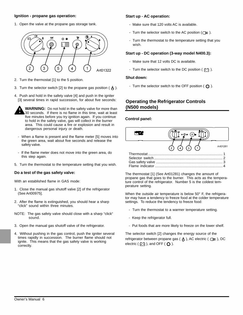
Ignition - propane gas operation:
1. Open the valve at the propane gas storage tank.
2. Turn the thermostat [1] to the 5 position.
3. Turn the selector switch [2] to the propane gas position ( ).
4. Push and hold in the safety valve [4] and push in the igniter[3] several times in rapid succession, for about five seconds:
WARNING: Do not hold in the safety valve for more than30 seconds. If there is no flame in this time, wait at leastfive minutes before you try ignition again. If you continueto hold in the safety valve, gas will collect in the burnerarea. This could cause a fire or explosion and result indangerous personal injury or death.
- When a flame is present and the flame meter [5] moves intothe green area, wait about five seconds and release thesafety valve.
- If the flame meter does not move into the green area, dothis step again.
5. Turn the thermostat to the temperature setting that you wish.
Do a test of the gas safety valve:
With an established flame in GAS mode:
1. Close the manual gas shutoff valve [2] of the refrigerator(See Art00975].
2. After the flame is extinguished, you should hear a sharp“click” sound within three minutes.
NOTE: The gas safety valve should close with a sharp “click“sound.
3. Open the manual gas shutoff valve of the refrigerator.
4. Without pushing in the gas control, push the igniter severaltimes rapidly in succession. The burner flame should notignite. This means that the gas safety valve is workingcorrectly.
Start up - AC operation:
- Make sure that 120 volts AC is available.
- Turn the selector switch to the AC position ( ).
- Turn the thermostat to the temperature setting that youwish.
Start up - DC operation (3-way model N400.3):
- Make sure that 12 volts DC is available.
- Turn the selector switch to the DC position ( ).
Shut down:
- Turn the selector switch to the OFF position ( ).
Owner’s Manual 7
The gas safety valve [3] is built into the control panel. As long asa flame is present, the valve is open and allows propane gas toflow into the burner. Any loss of flame (empty propane gas tank,blow out, etc.) closes the safety valve and stops the flow ofpropane gas.
The flame indicator [4] shows if a flame is present in the burner.
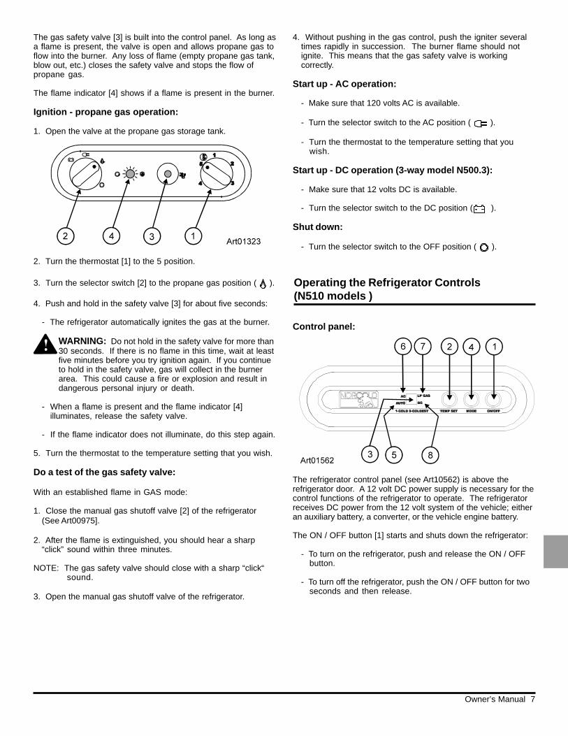
Ignition - propane gas operation:
1. Open the valve at the propane gas storage tank.
2. Turn the thermostat [1] to the 5 position.
3. Turn the selector switch [2] to the propane gas position ( ).
4. Push and hold in the safety valve [3] for about five seconds:
- The refrigerator automatically ignites the gas at the burner.
WARNING: Do not hold in the safety valve for more than30 seconds. If there is no flame in this time, wait at leastfive minutes before you try ignition again. If you continueto hold in the safety valve, gas will collect in the burnerarea. This could cause a fire or explosion and result indangerous personal injury or death.
- When a flame is present and the flame indicator [4]illuminates, release the safety valve.
- If the flame indicator does not illuminate, do this step again.
5. Turn the thermostat to the temperature setting that you wish.
Do a test of the gas safety valve:
With an established flame in GAS mode:
1. Close the manual gas shutoff valve [2] of the refrigerator(See Art00975].
2. After the flame is extinguished, you should hear a sharp“click” sound within three minutes.
NOTE: The gas safety valve should close with a sharp “click“sound.
3. Open the manual gas shutoff valve of the refrigerator.
4. Without pushing in the gas control, push the igniter severaltimes rapidly in succession. The burner flame should notignite. This means that the gas safety valve is workingcorrectly.
Start up - AC operation:
- Make sure that 120 volts AC is available.
- Turn the selector switch to the AC position ( ).
- Turn the thermostat to the temperature setting that youwish.
Start up - DC operation (3-way model N500.3):
- Make sure that 12 volts DC is available.
- Turn the selector switch to the DC position ( ).
Shut down:
- Turn the selector switch to the OFF position ( ).
Operating the Refrigerator Controls(N510 models )
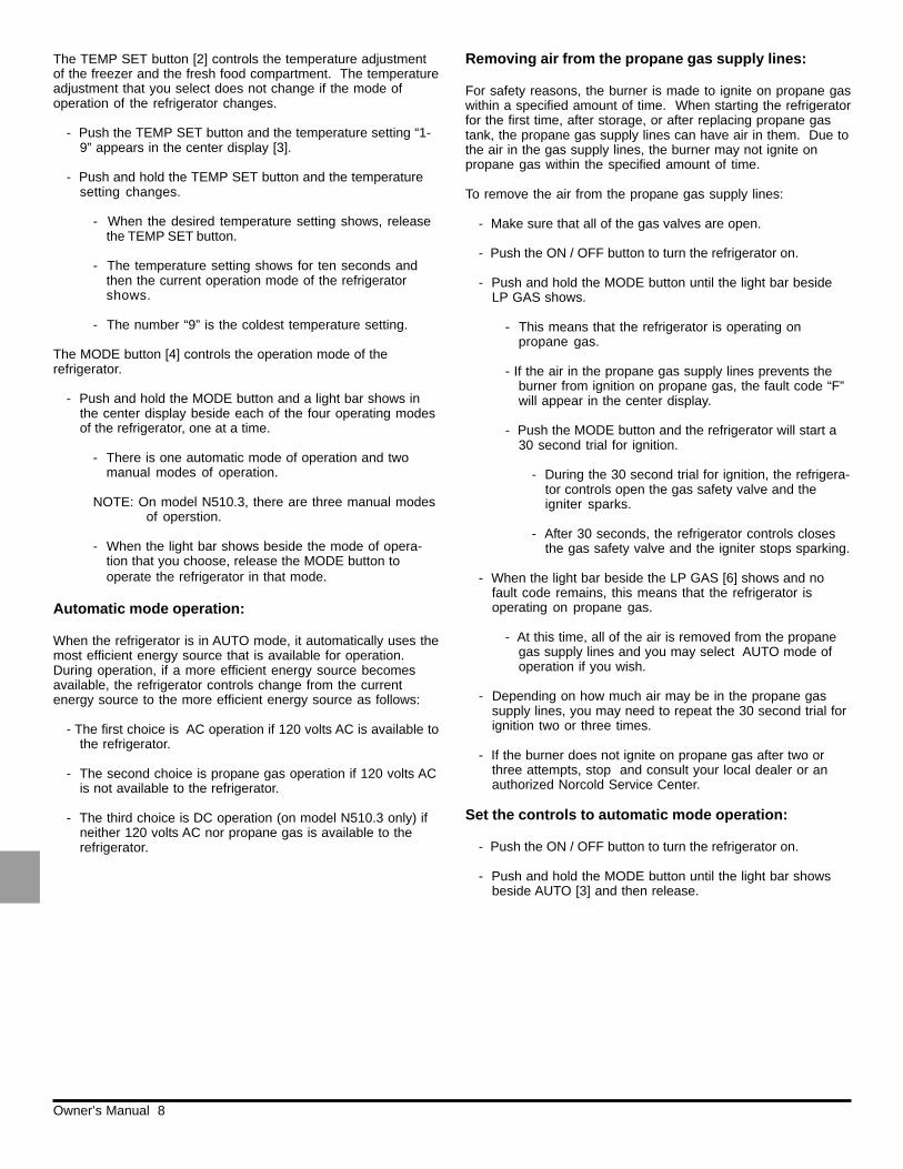
Control panel:
The refrigerator control panel (see Art10562) is above therefrigerator door. A 12 volt DC power supply is necessary for thecontrol functions of the refrigerator to operate. The refrigeratorreceives DC power from the 12 volt system of the vehicle; eitheran auxiliary battery, a converter, or the vehicle engine battery.
The ON / OFF button [1] starts and shuts down the refrigerator:
- To turn on the refrigerator, push and release the ON / OFFbutton.
- To turn off the refrigerator, push the ON / OFF button for twoseconds and then release.
Owner’s Manual 8
The TEMP SET button [2] controls the temperature adjustmentof the freezer and the fresh food compartment. The temperatureadjustment that you select does not change if the mode ofoperation of the refrigerator changes.
- Push the TEMP SET button and the temperature setting “1-9” appears in the center display [3].
- Push and hold the TEMP SET button and the temperaturesetting changes.
- When the desired temperature setting shows, releasethe TEMP SET button.
- The temperature setting shows for ten seconds andthen the current operation mode of the refrigeratorshows.
- The number “9” is the coldest temperature setting.
The MODE button [4] controls the operation mode of therefrigerator.
- Push and hold the MODE button and a light bar shows inthe center display beside each of the four operating modesof the refrigerator, one at a time.
- There is one automatic mode of operation and twomanual modes of operation.
NOTE: On model N510.3, there are three manual modesof operstion.
- When the light bar shows beside the mode of opera-tion that you choose, release the MODE button tooperate the refrigerator in that mode.
Automatic mode operation:
When the refrigerator is in AUTO mode, it automatically uses themost efficient energy source that is available for operation.During operation, if a more efficient energy source becomesavailable, the refrigerator controls change from the currentenergy source to the more efficient energy source as follows:
- The first choice is AC operation if 120 volts AC is available tothe refrigerator.
- The second choice is propane gas operation if 120 volts ACis not available to the refrigerator.
- The third choice is DC operation (on model N510.3 only) ifneither 120 volts AC nor propane gas is available to therefrigerator.
Removing air from the propane gas supply lines:
For safety reasons, the burner is made to ignite on propane gaswithin a specified amount of time. When starting the refrigeratorfor the first time, after storage, or after replacing propane gastank, the propane gas supply lines can have air in them. Due tothe air in the gas supply lines, the burner may not ignite onpropane gas within the specified amount of time.
To remove the air from the propane gas supply lines:
- Make sure that all of the gas valves are open.
- Push the ON / OFF button to turn the refrigerator on.
- Push and hold the MODE button until the light bar besideLP GAS shows.
- This means that the refrigerator is operating onpropane gas.
- If the air in the propane gas supply lines prevents theburner from ignition on propane gas, the fault code “F”will appear in the center display.
- Push the MODE button and the refrigerator will start a30 second trial for ignition.
- During the 30 second trial for ignition, the refrigera-tor controls open the gas safety valve and theigniter sparks.
- After 30 seconds, the refrigerator controls closesthe gas safety valve and the igniter stops sparking.
- When the light bar beside the LP GAS [6] shows and nofault code remains, this means that the refrigerator isoperating on propane gas.
- At this time, all of the air is removed from the propanegas supply lines and you may select AUTO mode ofoperation if you wish.
- Depending on how much air may be in the propane gassupply lines, you may need to repeat the 30 second trial forignition two or three times.
- If the burner does not ignite on propane gas after two orthree attempts, stop and consult your local dealer or anauthorized Norcold Service Center.
Set the controls to automatic mode operation:
- Push the ON / OFF button to turn the refrigerator on.
- Push and hold the MODE button until the light bar showsbeside AUTO [3] and then release.
Owner’s Manual 9
- If 120 volts AC is available to the refrigerator:
- The light bar beside AC [4] also shows in the centerdisplay.
- After ten seconds, the light bar beside AC goes off andonly the light bar beside AUTO remains.
- This means that the refrigerator is operating on ACelectric.
- If 120 volts AC is not available to the refrigerator:
- The light bar beside AC [4] also shows in the centerdisplay.
- After a few seconds, the light bar beside AC goes offand the light bar beside LP GAS [6] shows.
- After 10 seconds, the light bar beside LP GAS goes offand only the light bar beside AUTO remains.
- This means that the refrigerator is operating onpropane gas.
- On model N510 only, if neither 120 volts AC nor propanegas is available to the refrigerator:
- The fault code “F” shows in the center display.
- On model N510.3 only, if neither 120 volts AC nor propanegas is available to the refrigerator:
- The refrigerator control will automatically change to DCelectric operation.
NOTE: DC electric operation is less efficient than ACelectric and propane gas. Use DC electricoperation only to maintain the refrigeratortemperature while in transit and if the otherenergy sources are not available. Do not useDC electric to initially decrease the temperatureof the refrigerator.
If an energy source is available to the refrigerator, but is notoperating correctly:
- A fault code shows in the center display.
- The refrigerator controls try to change to a less efficientenergy source.
- If a less efficient energy source is not available:
- A fault code shows in the center display.
- Refer to the “Fault Codes” section of this manual.
Set the controls to manual mode operation:
- Push the ON / OFF button to turn the refrigerator on.
- Push and hold the MODE button until the light bar showsbeside AC [4] and then release.
- This means that the refrigerator is operating on ACelectric.
- Push and hold the MODE button until the light bar showsbeside LP GAS [6] and then release.
- This means that the refrigerator is operating onpropane gas.
- Push and hold the MODE button until the light bar showsbeside DC [8] and then release.
- This means that the refrigerator is operating on ACelectric.
If the energy source is interrupted:
- A fault code shows in the center display.
- Refer to the “Fault Codes” section of this manual.
Backup operating system:
This refrigerator has a backup operating system. The backupoperating system allows the refigerator to continue to cool if thetemperature sensor of the refrigerator should fail.
If this failure occurs:
- The refrigerator automatically changes to the backupoperating system.
- When you push the TEMP SET button, the temperaturesetting flashes in the center display for ten seconds.
- After the temperature setting flashes, the mode ofoperation appears in the center dispaly.
- The backup operating system can overfreeze or thaw thecontents of the freezer and the fresh food compartment.
- Make sure the temperatures of the freezer and the freshfood compartment are satisfactory.
NOTE: If you open the door(s) too often, the tempera-tures inside the freezer and fresh food compart-ment do not become stable. Allow the refrigera-tor to operate for about one hour after eachadjustment change before you examine thecontents. The number “9” is the coldesttemperature setting.
Owner’s Manual 10
Defrosting
Refrigerator Care Checklist
Your refrigerator will give you years of trouble free service if youdo these simple checks every three to six months:
- Keep the food compartment and the freezer clean. See“Cleaning”.
- Defrost the refrigerator as necessary. See “Defrosting”.
- Make sure the door seals correctly. See “Door Sealing“.
- Be aware of any cooling changes that are not because ofweather, loading, or gas control changes. If changes occur,contact your dealer or an authorized Norcold Service Center.
- Make sure the gas supply is propane gas only and notbutane or a butane mixture.
The cooling fins of the refrigerator operate at below freezingtemperature and will naturally form frost from humidity, which isalways present in the air. The humidity inside the refrigeratorincreases:
DC operation is intended only to maintain the temperature ofthe refrigerator and its contents when they are already cool.
The DC operation is not intended for the initial start up andcooling of the refrigerator. Always use either the AC operation orpropane gas operation to initially start up and cool the refrigera-tor. The refrigerator must be cooled and the temperature mustbe steady before you operate the refrigerator on DC.
This refrigerator is made to operate on DC power while yourvehicle is “in transit” and AC power or propane gas sources arenot available. Operate the refrigerator on DC power only whenthe vehicle engine is running.
For the refrigerator to operate correctly on DC power, the batterymust be maintained in a fully charged condition.
For the battery to be fully charged at all times during refrigeratoroperation on DC, the vehicle engine must be running and thebattery charging system must be in good operating condition.
Keep in mind the following electrical precautions for DCoperation of the refrigerator:
- Good battery condition is necessary for correct DC opera-tion.
- The capacity of the battery charging system must be morethan what is necessary for the refrigerator and other DCappliances.
- While the vehicle engine is running, make sure the voltageof the DC power supply leads at the refrigerator is morethan 11.5 VDC.
DC Operation Precautions (N400.3, N500.3,and N510.3 models)
DC Operation Guidelines (N400.3, N500.3, andN510.3 models)
- If the temperature is too warm, push and hold theTEMP SET button to raise the temperature settingby one number.
- If the temperature is too cold, push and hold theTEMP SET button to lower the temperature settingby one number.
- Have the refrigerator serviced by your dealer or an Norcoldauthorized Service Center as soon as possible.
Keep in mind the following guidelines for DC operation of therefrigerator:
- Use DC operation of the refrigerator while the vehicle is intransit.
- Do not use DC operation until the refrigerator and itscontents are completely cooled.
- Only use DC operation if the vehicle battery and batterycharging system are in good operating condition.
Effects of High Altitude on Propane GasOperation
When you operate the refrigerator on propane gas at altitudeshigher than 5500 feet above sea level:
- You may experience reduced cooling performance of therefrigerator.
- You may experience burner outages.
To avoid these possible problems, Norcold recommends thatyou operate the refrigerator on AC when at altitudes higher than5500 feet above sea level.
Owner’s Manual 11
Door Sealing
If the door does not seal correctly, excess frost will collect insidethe refrigerator. Make sure the door seals correctly:
- Close the door on a piece of paper that is about the sizeand thickness of a dollar bill (See Art00980).
- Gently pull the paper.
- You should feel a slight drag between the gasket andthe cabinet.
- Do this on all four sides of the door.
- If you do not feel a slight drag on thepaper, the door is not sealing correctly:
- Make sure the screws of the hinges are tight.
- Make sure the door gasket does not touch the doorlatch:
- If the door gasket touches the door latch,loosen the screws of the door latch.
- Raise the door latch just so it does not touchand tighten the screws of the door latch.
- Make sure the door latch holds the door closed
Refrigerator Maintenance Checklist
Read and understand the following maintenance sections ofthis manual.
NOTE: Norcold is not responsible for installation, adjustment,alteration, service, or maintenance performed byanyone other than a qualified RV dealer or anauthorized Norcold Service center.
Have a qualified RV dealer or an authorized Norcold ServiceCenter do these annual safety and maintenance checks:
- Examine the gas supply lines for leaks.
- Replace or repair if necessary.
- Make sure the propane gas pressure is 11 inches of watercolumn.
- Adjust if necessary.
- Make sure the combustion seal is complete and intact.
- Replace or repair it if necessary.
A good time to clean the refrigerator is just after you defrost it.
Clean the inside of the refrigerator as often as necessary toavoid food odors:
- Remove all food from the refrigerator.
NOTE: Do not use abrasive cleaners, chemicals, orscouring pads because they can damage theinterior of the refrigerator.
- Wash the interior with a solution of liquid dish detergentand warm water.
Cleaning
- with higher outside temperature and humidity.
- with the storage of non-sealed fresh foods or warm foods.
- with the amount of time that the door(s) are open.
- with any air leakage into the refrigerator.
It is normal for frost to collect inside the freezer. Excess frostdecreases the cooling performance of the refrigerator. Defrostthe refrigerator when frost statrs to close the spaces betweenthe cooling fins:
- Remove all food from the refrigerator.
- Shut off the refrigerator.
NOTE: Defrosting the refrigerator makes excess water insidethe refrigerator.
- Put dry towels (etc.) inside the refrigerator to absorb thewater.
- Put trays of hot water in the freezer until the frost is melted.
- Empty the drip tray.
- Remove the wet towels (etc.) and dry the interior.
- Put the drip tray and all food in the refrigerator.
- Start up the refrigerator.
N510 Models only:
Although the refrigerator is not frost -free, it is made to limit froston the cooling fins. At regular intervals, the temperature controlsystem automatically melts most of the frost from the coolingfins. The water from the cooling fins drains into a collection cupthat is attached to the back of the refrigerator. The heat of thecooling system evaporates the water from the collection cup.
Owner’s Manual 12
Refrigerator Maintenance
Gas flame appearance:
While in propane gas operation, examine the appearance of thegas flame:
- On N400 and N500 models, turn the thermostat to the 5position.
- On N510 models, push and hold temperature setting buttonuntil the “9” shows and then release.
- Open the lower intake vent.
CAUTION: The burner box cover can be hot. Weargloves to avoid burns.
- Open the burner box door [3] and look at the gas flame [1](See Art00955 and Art00975).
Refrigerator Storage
Before the refrigerator is stored for an extended (seasonal)period of time:
- Defrost and clean the interior of the refrigerator.
- Close the doors with the storage latch.
If the refrigerator is stored for an extended period of time, beforestart up:
- Make sure there are no obstructions in the vents, theventilation air pathway, the burner, the orifice, or the fluearea.
- Make sure the burner and the burner orifice are clean (SeeArt00956).
- Clean if necessary.
- Make sure the electrode spark gap [3] is 1/8 - 3/16 inch(See Art00955).
- Adjust if necessary.
- Make sure the AC voltage is 108 - 132 volts and the DCvoltage is 10.5 - 15.4 volts.
- Make sure the thermocouple tip is clean and secure.
- Make sure the area at the rear of the refrigerator is free ofany combustible materials, gasoline, and other flammablevapors and liquids.
- The flame should be:
- a darker blue color on the inside of the flame anda lighter blue color on the outside of the flame.
- a constant shape without flickering.
- Contact your dealer or Norcold authorized servicecenter if the flame is:
- yellow
- flickering or changing shape.
- Make sure the flame does not touch the inside of theflue tube [2].
- If the flame touches the inside of the flue tube, contactyour dealer or an authorized Norcold Service Center.
- Close the burner box door.
Remove and clean the burner orifice:
NOTE: Your dealer or an authorized Norcold Service Centermust do this procedure.
To remove and clean the burner orifice:
- Close the valve at the propane gas tank(s).
- Close the manual shut off valve of the refrigerator.
- Shut down the refrigerator..
- Open the lower intake vent.
CAUTION: The burner box cover can be hot. Weargloves to avoid burns.
- Remove the burner box cover by removing one screw.
WARNING: To avoid possible propane gas leaks,always use two wrenches to loosen and tighten thegas supply line at the refrigerator’s manual shut offvalve.
- Remove the flare nut from the orifice assembly [1] (SeeArt00956).
- Remove the orifice assembly from the burner [2].
WARNING: Do not try to remove the orifice [3] from theorifice adapter [4] when cleaning. Removal willdamage the orifice and seal of the orifice and cancause a propane gas leak. Leaking propane gas canignite or explode which can result in dangerouspersonal injury or death. Do not clean the orifice with apin or other objects.
Owner’s Manual 13
NOTE: Your dealer or an authorized Norcold Service Centermust do this procedure.
WARNING: Make sure the combustion seal is notbroken, is completely around the refrigerator mountingflanges, and is between the mounting flanges and thewall of the enclosure. If the combustion seal is notcomplete, exhaust fumes can be present in the livingarea of the vehicle. The breathing of exhaust fumes cancause dizziness, nausea, and in extreme cases, death.
1. Push the refrigerator completely into the enclosure.
2. Remove the door from the refrigerator.
3. Put the screws though the mounting flanges and into thewall.
4. Attach the door to the refrigerator
CAUTION: The rear of the refrigerator has sharp edgesand corners. To prevent cuts or abrasions when workingon the refrigerator, be careful and wear cut resistantgloves.
5. Open the lower intake vent and put the screws throughrefrigerator and into the floor.
WARNING: To avoid possible propane gas leaks,always use two wrenches to loosen and tighten the gassupply line at the refrigerator’s manual shut off valve.
6. Attach the gas supply line to the manual shut off valve of therefrigerator.
7. Open the valve at the propane gas tank(s).
WARNING: Do not allow the leak checking solution totouch the electrical components. Many liquids areelectrically conductive and can cause a shockhazard,electrical shorts, and in some cases fire.
8. Examine the gas supply line for leaks.
9. Connect the DC wiring to the refrigerator:
- Install the DC fuse or connect the DC wiring to the battery orthe converter.
- Connect the DC wires from the refrigerator.
10. Connect the AC power cord to the receptacle.
Replacement Parts
You may purchase replacement parts through your local RVdealer or an authorized Norcold Service Center.
Reinstall the Refrigerator
Remove the Refrigerator
NOTE: Your dealer or an authorized Norcold Service Centermust do this procedure.
CAUTION: The rear of the refrigerator has sharp edgesand corners. To prevent cuts or abrasions when workingon the refrigerator, be careful and wear cut resistantgloves.
1. Close the valve at the propane gas tank(s).
WARNING: To avoid possible propane gas leaks,always use two wrenches to loosen and tighten the gassupply line at the refrigerator’s manual shut off valve.
2. Open the lower intake vent and remove the gas supply linefrom the manual shut off valve of the refrigerator.
3. Remove the AC power cord from the receptacle.
4. Remove the DC wiring from the refrigerator:
- Remove the DC wiring from the battery or the converter ofthe vehicle.
- Put a mark on the DC wires so you can put them back in thecorrect location.
- Remove the DC wires from the refrigerator.
5. Remove the screws which fasten the refrigerator to the floor.
6. Remove the door from the refrigerator.
7. Remove the screws which fasten the refrigerator to the wall.
8. Remove the refrigerator from the opening.
9. Attach the door to the refrigerator.
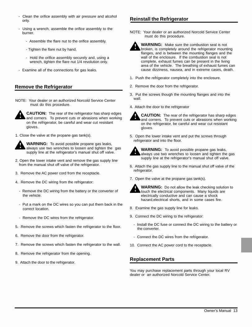
- Clean the orifice assembly with air pressure and alcoholonly.
- Using a wrench, assemble the orifice assembly to theburner.
- Assemble the flare nut to the orifice assembly.
- Tighten the flare nut by hand.
- Hold the orifice assembly securely and, using awrench, tighten the flare nut 1/4 revolution only.
- Examine all of the connections for gas leaks.
Owner’s Manual 14
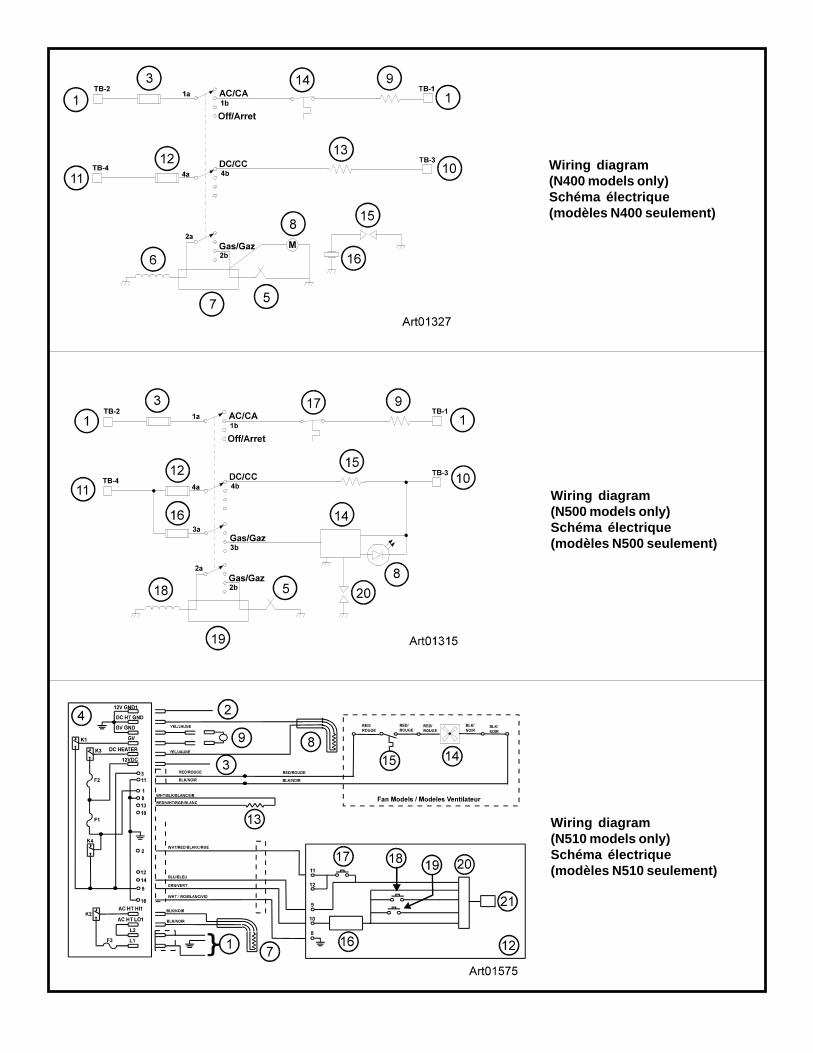
Wiring Diagram(N500 models only)
The parts of the wiring diagram are (See Art01315):
1 ............................................................................... 120 VAC3 ........................................................................... 3 Amp fuse5 ..................................................................... Thermocouple8 ................................................................... Flame indicator9 ............................................................................. AC heater10 .................................................................... -12 VDC Com11 ............................................................................. +12 VDC12 ............................................ 25 Amp fuse (model N500.3)14 ............................................................................ Relighter15 ............................................... DC heater (model N500.3)16 ......................................................................... 1 Amp fuse17 ........................................................................ Thermostat18 .................................................................Gas safety valve19 ................................................. Thermocouple interrupter20 .......................................................................... Spark gap
Wiring Pictorial(N510 models only)
The parts of the wiring pictorial are (Art01576):
1 ............................................................................... 120 VAC2 ........................................................ -12 VDC Power supply3 ....................................................... +12 VDC Power supply4 ........................................................................ Power board5 ........................................................................... 5 Amp fuse6 .............................................. 30 Amp fuse (model N510.3)7 ............................................................................. AC heater8 ................................................. DC heater (model N510.3)9 ...................................................................Gas safety valve10 ................................................................. Spark electrode11 ......................................................... Display board overlay12 .................................................................... Display board13 ......................................................... Temperature sensor14 .................................................................... Fan (optional)15 ........................................................Thermostat (optional)
Wiring Diagram(N510 models only)
The parts of the wiring diagram are (See Art01575):
1 ............................................................................... 120 VAC2 ........................................................ -12 VDC Power supply3 ....................................................... +12 VDC Power supply4 ........................................................................ Power board7 ............................................................................. AC heater8 ................................................. DC heater (model N510.3)9 ...................................................................Gas safety valve12 .................................................................... Display board13 ......................................................... Temperature sensor14 .................................................................... Fan (optional)15 ........................................................Thermostat (optional)16 ............................................................... Voltage regulator17 .................................................................ON / OFF switch18 ..................................................................... MODE switch19 .............................................................. TEMP SET switch20 ................................................................. Microprocessor21 .................................................................................... LED
Wiring Diagram(N400 models only)
The parts of the wiring diagram are (See Art01327):
1 ............................................................................... 120 VAC3 ........................................................................... 3 Amp fuse5 ..................................................................... Thermocouple6 ...................................................................Gas safety valve7 ................................................... Thermocouple interrupter8 ........................................................................ Flame meter9 ............................................................................. AC heater10 ......................................... -12 VDC Com (model N400.3)11 ...................................................+12 VDC (model N400.3)12 ............................................ 25 Amp fuse (model N400.3)13 ............................................... DC heater (model N400.3)14 ........................................................................ Thermostat15 .......................................................................... Spark gap16 ....................................................................... Piezo lighter
Wiring Pictorial(N500 models only)
The parts of the wiring pictorial are (Art01314):
1 .............................................................120VAC Power cord2 ..................................................................... Terminal block3 ........................................................................... 3 Amp fuse4 .................................................................... Selector switch5 ..................................................................... Thermocouple6 ..............................................Thermostat / gas safety valve7 ................................................... Thermocouple interrupter8 ................................................................... Flame indicator9 ............................................................................. AC heater10 ...................................................... -12 VDC Power supply11 ...................................................... +12 VDC Power supply12 ............................................ 25 Amp fuse (model N500.3)13 ................................................................. Spark electrode14 ............................................................................ Relighter15 ............................................... DC heater (model N500.3)16 ......................................................................... 1 Amp fuse
The parts of the wiring pictorial are (Art01326):
1 .............................................................120VAC Power cord2 ..................................................................... Terminal block3 ........................................................................... 3 Amp fuse4 .................................................................... Selector switch5 ..................................................................... Thermocouple6 ..............................................Thermostat / gas safety valve7 ................................................... Thermocouple interrupter8 ........................................................................ Flame meter9 ............................................................................. AC heater10 ........................... -12 VDC Power supply (model N400.3)11 ........................... +12 VDC Power supply (model N400.3)12 ............................................ 25 Amp fuse (model N400.3)13 ............................................... DC heater (model N400.3)
Wiring Pictorial(N400 models only)
Owner’s Manual 15
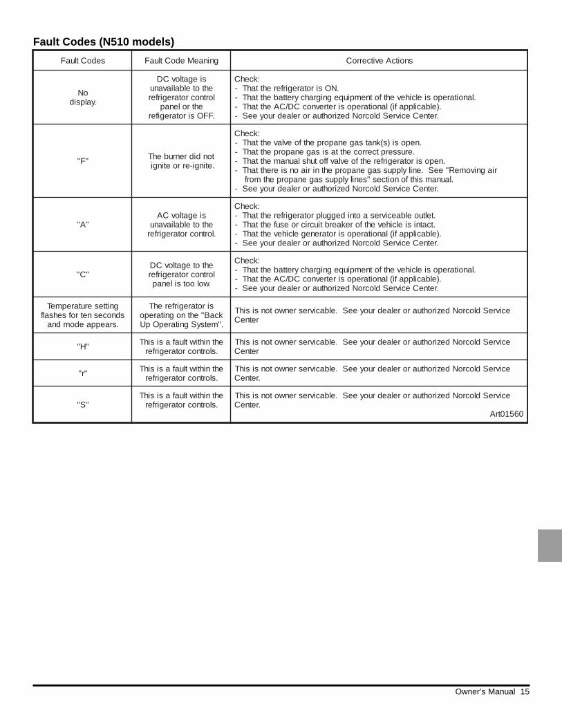
Fault Codes (N510 models)
sedoCtluaF gninaeMedoCtluaF snoitcAevitcerroC
oN.yalpsid
siegatlovCDehtotelbaliavanu
lortnocrotaregirferehtrolenap
.FFOsirotaregifer
:kcehC.NOsirotaregirferehttahT-
.lanoitareposielcihevehtfotnempiuqegnigrahcyrettabehttahT-.)elbacilppafi(lanoitareposiretrevnocCD/CAehttahT-
.retneCecivreSdlocroNdezirohtuarorelaedruoyeeS-
"F" tondidrenrubehT.etingi-erroetingi
:kcehC.neposi)s(knatsagenaporpehtfoevlavehttahT-
.erusserptcerrocehttasisagenaporpehttahT-.neposirotaregirferehtfoevlavffotuhslaunamehttahT-
riagnivomeR"eeS.enilylppussagenaporpehtniriaonsierehttahT-.launamsihtfonoitces"senilylppussagenaporpehtmorf
.retneCecivreSdlocroNdezirohtuarorelaedruoyeeS-
"A"siegatlovCA
ehtotelbaliavanu.lortnocrotaregirfer
:kcehC.teltuoelbaecivresaotnideggulprotaregirferehttahT-.tcatnisielcihevehtforekaerbtiucricroesufehttahT-
.)elbacilppafi(lanoitareposirotarenegelcihevehttahT-.retneCecivreSdlocroNdezirohtuarorelaedruoyeeS-
"C"ehtotegatlovCDlortnocrotaregirfer
.wolootsilenap
:kcehC.lanoitareposielcihevehtfotnempiuqegnigrahcyrettabehttahT-
.)elbacilppafi(lanoitareposiretrevnocCD/CAehttahT-.retneCecivreSdlocroNdezirohtuarorelaedruoyeeS-
gnitteserutarepmeTsdnocesnetrofsehsalf
.sraeppaedomdna
sirotaregirferehTkcaB"ehtnognitarepo."metsySgnitarepOpU
ecivreSdlocroNdezirohtuarorelaedruoyeeS.elbacivresrenwotonsisihTretneC
"H" ehtnihtiwtluafasisihT.slortnocrotaregirfer
ecivreSdlocroNdezirohtuarorelaedruoyeeS.elbacivresrenwotonsisihTretneC
"r" ehtnihtiwtluafasisihT.slortnocrotaregirfer
ecivreSdlocroNdezirohtuarorelaedruoyeeS.elbacivresrenwotonsisihT.retneC
"S"ehtnihtiwtluafasisihT
.slortnocrotaregirferecivreSdlocroNdezirohtuarorelaedruoyeeS.elbacivresrenwotonsisihT
.retneC06510trA
1
25
4 3
12 3 45 Art01280
Art01114
1
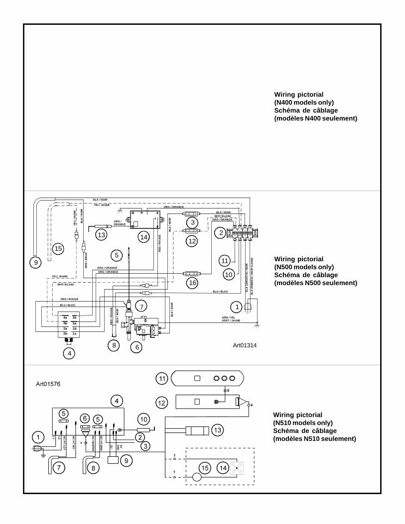
Wiring pictorial(N500 models only)Schéma de câblage(modèles N500 seulement)
9
15
13
5
7
8 64
3
1
10
11
12
16
14
Art01314
RED / ROUGE
RE
D /
RO
UG
E
BR
N /
BR
UN
4a
4b
2a
2b
3b
3a
1a1b
ORG / ORANGE
ORG /ORANGE
ORG / ORANGE
BLK / NOIR
BL
K /
NO
IRBLU / BLEU
GRN / YELVERT / JAUNE
BLU / BLEU
BLK / NOIR
YE
L/ J
AU
NE
BL
K /
NO
IR
YEL/ JAUNE
1234
5678
BLK
(SM
OO
TH
) / N
OIR
BL
K (R
IBB
ED
) / N
OIR
(CA
NN
)
BL
K /
NO
IR
RE
D /
RO
UG
E
YEL/ JAUNE
WHT/ BLANC
ORG / ORANGE
BL
K /
NO
IR
WHT/ BLANCORG / ORANGE
2
Wiring pictorial(N400 models only)Schéma de câblage(modèles N400 seulement)
Wiring pictorial(N510 models only)Schéma de câblage(modèles N510 seulement)
Wiring diagram(N400 models only)Schéma électrique(modèles N400 seulement)
Wiring diagram(N500 models only)Schéma électrique(modèles N500 seulement)
Wiring diagram(N510 models only)Schéma électrique(modèles N510 seulement)