owners manual - diversitech
TRANSCRIPT
1
OWNERS MANUAL
FOR
D-Tech Model T3500/T4500
INDUSTRIAL AIR CLEANER
CONTENTS:
SAFETY/INSPECTION…………………...……………………………………. 2
SPECIFICATIONS……………….……………………………………………... 3
INSTALLATION………………………………………………………………… 4
REPLACEMENT PARTS………………………………………………………. 5
ELECTRICAL …………………………………………….……………………. 6
TROUBLESHOOTING/NOTES:….…………………………………………... 8
WARRANTY…………………………………………………………………… 13
1200 55th AvenueMontreal, Quebec H8T 3J8
www.diversitech.ca
2
SAFETY
PLEASE READ THE FOLLOWING INSTRUCTIONS CAREFULLY BEFORE INSTALLING,
OPERATING OR SERVICING YOUR AIR CLEANER.
Follow all building and safety codes when installing this equipment. Pertaining but not limited to, the
Occupational Safety and Health Act (OSHA), National Electric Code (NEC), Uniform Building Code (UBC),
National Fire Prevention Act (NFPA) & all state and local codes.
All electrical connections should be performed by a qualified electrician.
Keep Flammable Objects away from the air cleaner and under no condition should a burning object be allowed
into the air cleaning system.
Take proper caution in placing units in buildings with radiant heaters installed. Follow the radiant heater
manufacturer’s guidelines for clearance to combustibles.
Do not mix materials collected in your Air Cleaner. Materials collected could create a hazardous environment
or a condition of operation for which the equipment was not intended. The Manufacturer is relieved of any
liability if this unit is not used according to this manual.
Do not use the Air Cleaner for an application other than for which it was intended. Consult your distributor,
Applicable Codes, or call Diversi-tech for application assistance.
Fire protection is not included. Please consult your local fire protection specialist for any required extinguishing
equipment.
Consult with your insurance underwriter about any other protection from fire damages.
The Manufacturer reserves the right to make design changes which may improve the air cleaner.
This unit is intended for use to collect ambient dust, smoke, fume and other airborne pollutants in industrial and
manufacturing Facilities . Do not use for the collection of flammable or explosive metals, dusts, fumes or other
potentially hazardous materials.
INSPECTION
Upon receiving your Diversi-tech air cleaner, please inspect for any damage incurred during shipment. Inspect
carefully, some damage may not be noticeable until the unit is installed. Notify your shipper of any damage
immediately. Claims must be filed with the shipper within 15 days. Freight damage claims are the
responsibility of the purchaser.
3
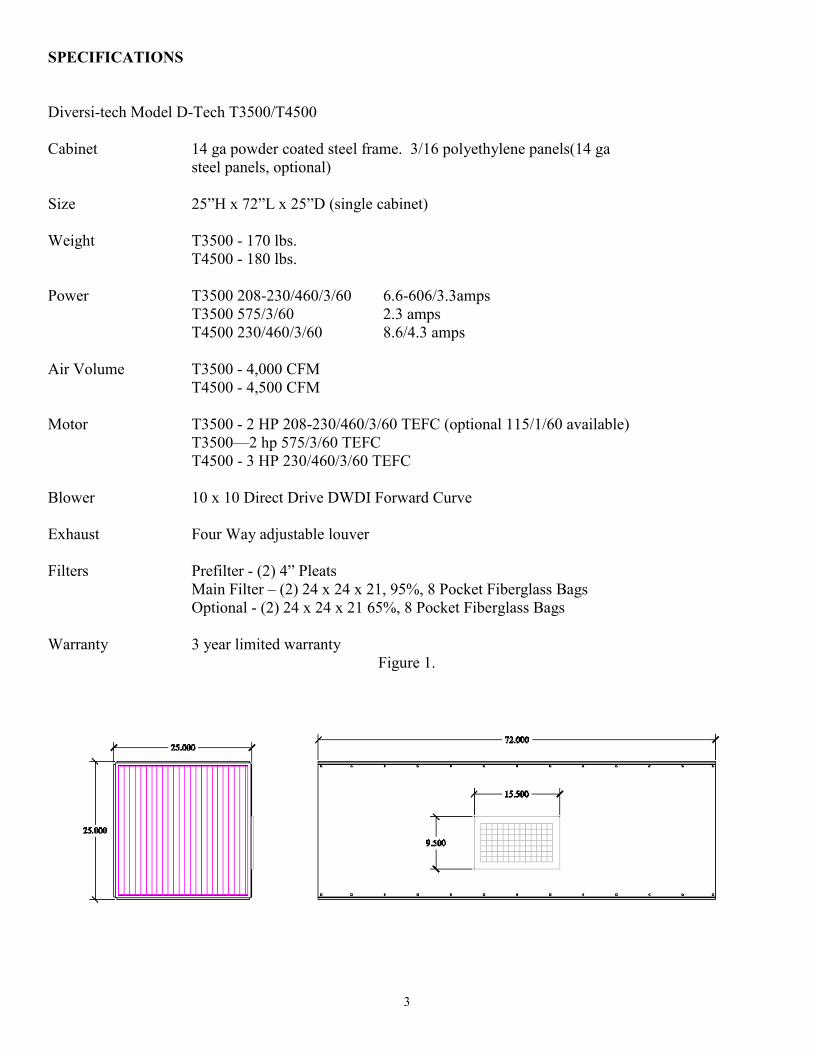
SPECIFICATIONS
Diversi-tech Model D-Tech T3500/T4500
Cabinet 14 ga powder coated steel frame. 3/16 polyethylene panels(14 ga
steel panels, optional)
Size 25”H x 72”L x 25”D (single cabinet)
Weight T3500 - 170 lbs.
T4500 - 180 lbs.
Power T3500 208-230/460/3/60 6.6-606/3.3amps
T3500 575/3/60 2.3 amps
T4500 230/460/3/60 8.6/4.3 amps
Air Volume T3500 - 4,000 CFM
T4500 - 4,500 CFM
Motor T3500 - 2 HP 208-230/460/3/60 TEFC (optional 115/1/60 available)
T3500—2 hp 575/3/60 TEFC
T4500 - 3 HP 230/460/3/60 TEFC
Blower 10 x 10 Direct Drive DWDI Forward Curve
Exhaust Four Way adjustable louver
Filters Prefilter - (2) 4” Pleats
Main Filter – (2) 24 x 24 x 21, 95%, 8 Pocket Fiberglass Bags
Optional - (2) 24 x 24 x 21 65%, 8 Pocket Fiberglass Bags
Warranty 3 year limited warranty
Figure 1.

4
INSTALLATION
The system’s weight must be taken into account when choosing the proper installation method (see
specification). Follow all applicable building and electrical codes.
There are three main ways of installing your Model 3500 air cleaner, Chain Hanging (eye bolts factory installed
as option), rod & cradle , or angle braces. Figure 2 illustrates these methods. Do not chain mount double
cabinet units, use (4) 5/8” threaded rod and cradle the collector (lower right, figure 2).
Figure 2
Mounting materials must be able to support the weight of the air cleaner plus the additional weight of the
material collected. Consult your local building code for proper installation methods and materials. Failure to
use the proper materials could result in injury or damage equipment and will void the warranty.

5
REPLACEMENT PARTS

6
3 PHASE ELECTRICAL WIRING DIAGRAM
Unit comes wired to a junction box Additional wiring will be required to get power to unit, which is not supplied with this prod-
uct.
Motor Starters, disconnect, wiring, overloads, and thermal protection are NOT provided by the Manufacturer
All Field wiring should be performed by a qualified electrician and must meet all local, NFPA and NEC codes. Failure to install
the proper electrical wiring, thermal protection, and controls will void the warranty.
After completion of the field wiring, turn the unit on to check for proper rotation. Rotation is marked on the side of the blower
housing. Backward rotation will result in a much lower air flow, louder noise, and will over amp the motor. Check the motor
nameplate before switching wires and reversing rotation, to ensure the unit is operating at or below rated amp draw.
7
Motor Mounting
Motor must be securely fastened to a rigid, flat surface to prevent vibration and minimize noise. For secure mounting use high-quality bolts of
the largest possible diameter.
Belt-drive sheaves must be in-line. Use a straight edge to check. Do not over-tighten belts.
Direct coupled installations require a careful check of shaft and coupling alignment, shaft offset and/or angular misalignment should be less
than .002”. Shim motor base as necessary. Do not depend on a flexible coupling to compensate for misalignment.
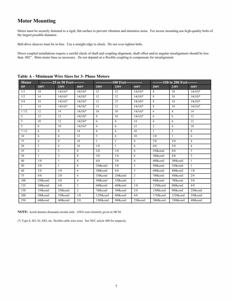
Table A - Minimum Wire Sizes for 3- Phase Motors
NOTE: kcmil denotes thousand circular mils. AWG sizes formerly given in MCM.
(*) Type S, SO, SJ, SJO, etc. flexible cable wire sizes. See NEC article 400 for ampacity.
Motor ---------25 to 50 Feet--------- -------------100 Feet------------- --------150 to 200 Feet-------- HP 200V 230V 460V 200V 230V 460V 200V 230V 460V
1/3 14 14(16)* 14(18)* 12 12 14(18)* 8 10 14(18)*
1/2 14 14(16)* 14(18)* 12 12 14(18)* 8 10 14(18)*
3/4 14 14(16)* 14(18)* 12 12 14(18)* 8 10 14(18)*
1 14 14(16)* 14(18)* 12 12 14(18)* 8 10 14(16)*
1 1/2 12 14 14(18)* 10 10 14(16)* 6 8 14
2 12 12 14(18)* 8 10 14(16)* 6 6 12
3 10 12 14(18)* 6 8 14 4 6 12
5 8 10 14(16)* 4 6 12 2 4 10
7 1/2 6 8 14 4 4 10 1 2 8
10 6 6 12 3 4 10 1/0 1 6
15 4 4 10 1 2 8 3/0 2/0 4
20 3 4 10 1/0 1 6 4/0 3/0 4
25 2 3 8 2/0 1/0 6 250kcmil 4/0 3
30 1 3 8 3/0 1/0 6 300kcmil 4/0 3
40 1/0 1 8 4/0 3/0 4 400kcmil 300kcmil 1
50 2/0 1 6 250kcmil 3/0 3 500kcmil 350kcmil 1
60 3/0 1/0 6 300kcmil 4/0 3 600kcmil 400kcmil 1/0
75 4/0 2/0 4 350kcmil 250kcmil 2 700kcmil 500kcmil 2/0
100 250kcmil 3/0 4 500kcmil 350kcmil 1 900kcmil 700kcmil 3/0
125 300kcmil 4/0 3 600kcmil 400kcmil 1/0 1250kcmil 800kcmil 4/0
150 350kcmil 250kcmil 2 700kcmil 500kcmil 2/0 1500kcmil 900kcmil 250kcmil
200 500kcmil 350kcmil 1/0 1250kcmil 800kcmil 4/0 1750kcmil 1250kcmil 350kcmil
250 600kcmil 400kcmil 2/0 1500kcmil 900kcmil 250kcmil 2000kcmil 1500kcmil 400kcmil

8
Connecting Power to MotorTo connect motor for proper voltage and rotation, refer to the connection diagram on the nameplate or inside the terminal/conduit box.
Table B - Minimum Wire Sizes for Single Phase Motors
* Type S, SO, SJ, SJO, etc. Flexible cable wire sizes. See NEC Article 400 for ampacity.
NOTE: NEC Article 310-5 --- Minimum conductor size for general wiring at 115-440VAC is No. 14AWG.Above wire sizes based on
approximate 5% voltage drop during starting; copper conductors; and 75° C type THHW,
THW, THWN, RH, RHW insulation, etc. For aluminum wire, increase two wire size steps minimum. See NEC Article 310
for ampacities of aluminum conductors.
All aspects of the installation must conform to the requirements of the NEC, including Article 430 (Motor circuits and Controllers), and
all local codes. Wherever possible, each motor should be powered from a separate circuit of adequate capacity to keep voltage
drop to a minimum during starting and running. Increase wire size where motor is located a distance from the power source. Wire size
must be adequate to minimize voltage drop during starting and running. Refer to Tables A and B for suggested wire sizes. Distances shown
are one-way between source and motor. Portable cords, if used, should be as short as possible to minimize voltage drop. Long or inade-
quately sized cords, especially on hard starting loads, can cause motor failure. All electrical connections in system must be secure to pre-
vent voltage drop and localized heating.
* Determine direction of rotation before connecting driven equipment to prevent damage.
* To prevent bearing damage, do not strike shafts with hammer or other tool.
* If the motor has been damp or wet, then have motor serviced by a qualified motor repair shop before operating.
Recommended Maintenance Remove dirt accumulations in and around vent openings, by vacuuming. Dirt accu-
mulations can cause motor overheating and a fire hazard. Enclosed motors can be cleaned with an air jet; wear eye protection.
Periodically inspect the installation. Check for dirt accumulations; unusual noises or vibration; overheating; worn or loose couplings,
sheaves and belts; high motor current; poor wiring or overheated connections; loose mounting bolts or guards; and worn motor starter con-
tacts.
Dayton ball-bearing motors without lubrication provision do not require periodic relubrication. Where motor has provision for bearing lu-
brication, lubricate as follows:
1. After stopping motor and disconnection power, thoroughly wipe the housing around both of the motor bearings, filler and drain plugs (on
TEFC) ratings, remove fan cover for access to plugs).
2. Remove filler and drain plugs and install a 1/8” pipe thread lube fitting in filler hole.
3. Using a low pressure grease gun, pump new grease into motor until it appears at the drain hole.
4. Run motor for several minutes to discharge excess grease. Shut motor OFF, replace filler and drain plugs, and reinstall fan cover.
See Table C for suggested regreasing intervals.
Motor ---25 Feet---- ---50 Feet---- ---100 Feet---- ---150 Feet---- ---200 Feet---- HP 115V 230V 115V 230V 115V 230V 115V 230V 115V 230V
1 10 14(16)* 6 12 4 10 2 8 1 6
1 1/2 8 14 6 12 3 8 1 6 1/0 6
2 8 14 4 10 2 8 1/0 6 2/0 4
3 6 12 3 8 1/0 6 2/0 4 4/0 3
5 - 10 - 6 - 4 - 2 - 1
7 1/2 - 8 - 6 - 3 - 1 - 1/0
10 - 8 - 4 - 2 - 1/0 - 2/0
WARNING
9
TROUBLESHOOTING CHART
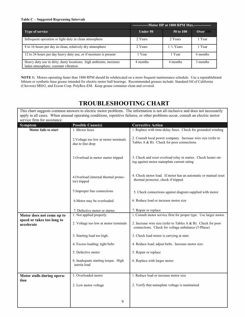
Table C – Suggested Regreasing Intervals
NOTE 1: Motors operating faster than 1800 RPM should be relubricated on a more frequent maintenance schedule. Use a reputablebrand
lithium or synthetic-base grease intended for electric motor ball bearings. Recommended greases include: Standard Oil of California
(Chevron) SRI#2, and Exxon Corp. PolyRex-EM. Keep grease container clean and covered.
-------------Motor HP at 1800 RPM Max.--------------
Type of service Under 50 50 to 100 Over 100
Infrequent operation or light duty in clean atmosphere 2 Years 2 Years 1 Year
8 to 16 hours per day in clean, relatively dry atmosphere 2 Years 1 ½ Years 1 Year
12 to 24 hours per day heavy duty use, or if moisture is present 1 Year 1 Year 6 months
Heavy duty use in dirty, dusty locations; high ambients; moisture
laden atmosphere; constant vibration 4 months 4 months 3 months
This chart suggests common answers to electric motor problems. The information is not all-inclusive and does not necessarily
apply in all cases. When unusual operating conditions, repetitive failures, or other problems occur, consult an electric motor
service firm for assistance.
Symptom Possible Cause(s) Corrective Action
Motor fails to start 1. Blown fuses
2.Voltage too low at motor terminals
due to line drop
3.Overload in motor starter tripped
4.Overload (internal thermal protec-
tor) tripped
5.Improper line connections
6.Motor may be overloaded
7. Defective motor or starter.
1. Replace with time-delay fuses. Check for grounded winding
2. Consult local power company. Increase wire size (refer to
Tables A & B). Check for poor connections
3. Check and reset overload relay in starter. Check heater rat-
ing against motor nameplate current rating
4. Check motor load. If motor has an automatic or manual reset
thermal protector, check if tripped
5. Check connections against diagram supplied with motor
6. Reduce load or increase motor size
7. Repair or replace
Motor does not come up to
speed or takes too long to
accelerate
1. Not applied properly.
2. Voltage too low at motor terminals
3. Starting load too high.
4. Excess loading; tight belts
5. Defective motor
6. Inadequate starting torque. High
inertia load
1. Consult motor service firm for proper type. Use larger motor.
2. Increase wire size (refer to Tables A & B). Check for poor
connections. Check for voltage unbalance (3-Phase)
3. Check load motor is carrying at start.
4. Reduce load; adjust belts. Increase motor size.
5. Repair or replace
6. Replace with larger motor
Motor stalls during opera-
tion
1. Overloaded motor
2. Low motor voltage
1. Reduce load or increase motor size
2. Verify that nameplate voltage is maintained

10
Motor vibrates or is
excessively noisy
1. Motor shaft misaligned
2. 3-phase motor running on single phase
3. High or unbalanced voltages
4. Worn, damaged, dirty or overloaded bear-
ings
5. Defective winding. Bent or bowed shaft
6. Loose sheave or misaligned coupling
1. Realign
2. Check for open circuit, blown fuses or unbalanced volt-
ages
3. Check wiring connections. Consult local power company
4 Replace bearings; check loading and alignment
5. Repair or replace
6. Tighten set screw(s); realign coupling
Motor overheats
while running under
load
1. Overloaded
2. Dirt blocking
3. If 3-Phase, one phase may be open
4. Unbalanced supply voltage
5. Faulty connection
6. High or low voltage
7. Defective motor
1. Reduce load; adjust belts. Increase motor size.
2. Clean motor
3. Check lines for open phase. Check voltage with motor
disconnected, one fuse may be blown.
4. Check for faulty connections. Voltage on all three lines
should be balanced within 1%. Balance single phase loads.
5. Clean, tighten, or replace
6. Check voltage at motor, should not be more than 10%
above or below rated
7. Repair or replace
NOTES:
______________________________________________________________________________________________________
______________________________________________________________________________________________________
Motor troubleshooting (cont.)
2500 Alphonse Gariepy, Montreal, QC H8T 3M2
CANADA
www.diversitech.ca
800-361-3733
11
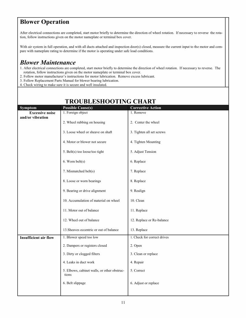
Blower Operation
After electrical connections are completed, start motor briefly to determine the direction of wheel rotation. If necessary to reverse the rota-
tion, follow instructions given on the motor nameplate or terminal box cover.
With air system in full operation, and with all ducts attached and inspection door(s) closed, measure the current input to the motor and com-
pare with nameplate rating to determine if the motor is operating under safe load conditions.
Blower Maintenance1. After electrical connections are completed, start motor briefly to determine the direction of wheel rotation. If necessary to reverse. The
rotation, follow instructions given on the motor nameplate or terminal box cover.
2. Follow motor manufacturer’s instructions for motor lubrication. Remove excess lubricant.
3. Follow Replacement Parts Manual for blower bearing lubrication.
4. Check wiring to make sure it is secure and well insulated.
TROUBLESHOOTING CHARTSymptom Possible Cause(s) Corrective Action
Excessive noise
and/or vibration
1. Foreign object
2. Wheel rubbing on housing
3. Loose wheel or sheave on shaft
4. Motor or blower not secure
5. Belt(s) too loose/too tight
6. Worn belt(s)
7. Mismatched belt(s)
8. Loose or worn bearings
9. Bearing or drive alignment
10. Accumulation of material on wheel
11. Motor out of balance
12. Wheel out of balance
13.Sheaves eccentric or out of balance
1. Remove
2. Center the wheel
3. Tighten all set screws
4. Tighten Mounting
5. Adjust Tension
6. Replace
7. Replace
8. Replace
9. Realign
10. Clean
11. Replace
12. Replace or Re-balance
13. Replace
Insufficient air flow 1. Blower speed too low
2. Dampers or registers closed
3. Dirty or clogged filters
4. Leaks in duct work
5. Elbows, cabinet walls, or other obstruc-
tions
6. Belt slippage
1. Check for correct drives
2. Open
3. Clean or replace
4. Repair
5. Correct
6. Adjust or replace
12
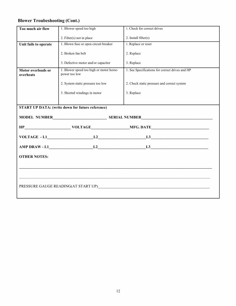
Too much air flow 1. Blower speed too high
2. Filter(s) not in place
1. Check for correct drives
2. Install filter(s)
Unit fails to operate 1. Blown fuse or open circuit breaker
2. Broken fan belt
3. Defective motor and/or capacitor
1. Replace or reset
2. Replace
3. Replace
Motor overloads or
overheats
1. Blower speed too high or motor horse-
power too low
2. System static pressure too low
3. Shorted windings in motor
1. See Specifications for correct drives and HP
2. Check static pressure and correct system
3. Replace
START UP DATA: (write down for future reference)
MODEL NUMBER____________________________ SERIAL NUMBER_____________________________________
HP________________________ VOLTAGE____________________MFG. DATE______________________________
VOLTAGE - L1________________________L2_________________________L3______________________________
AMP DRAW - L1_______________________L2_________________________L3______________________________
OTHER NOTES:
____________________________________________________________________________________________________
___________________________________________________________________________________________________
PRESSURE GAUGE READING(AT START UP)__________________________________________________________
Blower Troubeshooting (Cont.)

13
WARRANTY STATEMENT
3 Year Limited Warranty
ITEMS NOT COVERED WITHIN THIS WARRANTY ARE THE FILTERS AND DUCTWORK, WIRING AND INSTALLA-
TION NOT SUPPLIED BY DIVERSI-TECH INC.
DIVERSI-TECH INC. WARRANTS THAT ALL NEW AIR CLEANERS AND AIR FILTRATION EQUIPMENT ARE FREE
FROM DEFECTS IN MATERIAL AND WORKMANSHIP UNDER NORMAL USE AND SERVICE. DIVERSI-TECH WILL
REMEDY ANY SUCH DEFECTS IF THEY APPEAR 36 MONTHS FROM THE DATE OF PURCHASE, SUBJECT TO THE
TERMS AND CONDITIONS OF THIS LIMITED 3 YEAR WARRANTY LISTED BELOW.
1. THIS LIMITED WARRANTY IS GRANTED BY DIVERSI-TECH INC.
2. THIS WARRANTY SHALL EXTEND TO ANY OWNER WHO HAS PURCHSED THE EQUIPMENT OTHER THAN
FOR THE PURPOSE OF RESALE.
3. ALL COMPONENTS MANUFACTURED BY DIVERSI-TECH INC. ARE COVERED BY THIS WARRANTY.
4. IF WITHIN THE WARRANY PERIOD ANY DIVERSI-TECH UNIT OR COMPONENT REQUIRES SERVICE, IT
MUST BE PERFORMED BY DIVERSI-TECH OR AN AUTHORIZED DIVERSI-TECH DISTRIBUTOR. DIVERSI-TECH
WILL NOT PAY SHIPPING CHARGES OR LABOR CHARGES TO REMOVE OR REPLACE SUCH DEFECTIVE PARTS
OR COMPONENTS. IF THE PART OR COMPONENT IS FOUND BY INSPECTION TO CONTAIN SUCH DEFECTS IN
MATERIAL AND WORKMANSHIP, IT WILL BE REPAIRED OR REPLACED FREE OF CHARGE AND RETURNED
FREIGHT COLLECT.
5. IN ORDER TO OBTAIN THE BENEFITS OF THIS WARRANTY, THE OWNER MUST NOTIFY THE DISTRIBUTOR
OR DIVERSI-TECH OF THE DEFECT WITHIN 30 DAYS OF ITS DISCOVERY.
6. THIS LIMITED WARRANTY DOES NOT APPLY TO ANY PART OR COMPONENT THAT IS DAMAGED IN TRAN-
SIT OR WHEN HANDLING; HAS BEEN SUBJECT TO MISUSE, NEGLECT OR ACCIDENT; HAS NOT BEEN IN-
STALLED, OPERATED OR SERVICED ACCORDING DIVERSI-TECH’S INSTRUCTION; HAS BEEN OPERATED BE-
YOND THE FACTORY RATED CAPACITY; OR ALTERED IN ANY WAY THAT WOULD AFFECT ITS PERFORMANCE.
THERE IS NO WARRANT DUE TO NEGLECT, ALTERATION OR ORDINARY WEAR AND TEAR. DIVERSI-TECH’S
LIABILITY IS LIMITED TO REPLACEMENT OF DEFECTIVE COMPONENTS AND DOES NOT INCLUDE THE PAY-
MENT OF THE COST OF LABOR CHARGES TO REMOVE THE PART OR REPLACE SUCH PARTS OR COMPONENTS.
7. DIVERSI-TECH WILL NOT BE RESPONSIBLE FOR LOSS OF USE OF ANY PRODUCT; LOSS OF TIME, INCON-
VENIENCE, OR ANY OTHER INDIRECT, INCIDENTAL OR CONSEQUENTIAL DAMAGES WITH RESPECT TO PER-
SONAL PROPERTY, WHETHER AS A RESULT OF BREACH OF WARRANTY, NEGLECT OR OTHERWISE. SOME
STATES DO NOT ALLOW THE EXCLUSION OR LIMITATION OF INCIDENTAL OR CONSEQUENTIAL DAM-
AGES, SO THE EXCLUSION OR LIMITATION IN THE PRECEEDING SENTENCE MAY NOT APPLY TO YOU.
8. THIS WARRANTY GIVES YOU SPECIFIC RIGHTS, AND YOU MAY ALSO HAVE OTHER RIGHTS THAT VARY
FROM STATE TO STATE.
9. ANY WARRANTY WORK WILL BE PERFORMED IN A REASONABLE AMOUNT OF TIME, USUALLY WITHIN 60
DAYS AFTER THE NOTE OF DEFECT, SUBJECT TO DELAY BEYOND DIVERSI-TECH’S CONTROL.
10. ANY WARRANY BY DIVERSI-TECH OF MERCHANT ABILITY, FITNESS FOR USE OR ANY OTHER WARRANTY
(EXPRESS, IMPLIED OR STATUTORY), REPRESENTATION OR GURANTEE OTHER THAN THOSE SET FORTH
HERIN, SHALL EXPIRE AT THE EXPIRATION DATE OF THIS EXPRESS LIMITED WARRANTY. SOME STATES DO
NOT ALLOW LIMITATIONS ON HOW LONG AN IMPLIED WARRANTY LASTS, SO THE LIMITATIONS IN THE
PRECEEDING SENTENCE MAY NOT APPLY TO YOU.
11. DIVERSI-TECH RESERVES THE RIGHT TO MAKE CHANGES IN THE DESIGN AND MATERIAL OF ITS PROD-
UCTS WITHOUT INCURRING ANY OBLIGATION TO INCORPORATE SUCH CHANGES IN ITS UNITS COMPLETED
ON THE EFFECTIVE DATE OF SUCH CHANGE.
1200 55th AvenueMontreal, Quebec H8T 3J8 www.diversitech.ca
800-361-3733