owner's manual for vehicle - wedophones.comwedophones.com/manuals/bmw/2004 z4 3-0i owner's...
TRANSCRIPT
Owner's Manualfor Vehicle

Z4 2.5iZ4 3.0i
Congratulations, and thank you for choosing a BMW.
Thorough familiarity with your vehicle will provide you with enhanced control and security when you drive it. There-fore, we have one request:
Please take the time to read this Owner's Manual and familiarize yourself with the information that we have com-piled for you before starting off in your new BMW. The manual contains important data and instructions intended to assist you in obtaining maximum satisfaction from your BMW's unique array of advanced technical features. It also contains information on vehicle maintenance designed to enhance operating safety while simultaneously helping you to maintain your BMW's value throughout an extended ser-vice life. For additional information refer to the supplemen-tal manuals.
This Owner's Manual should be considered a permanent part of this vehicle. It should stay with the vehicle when sold to provide the next owner with important operating, safety and maintenance information.
We wish you an enjoyable driving experience.
BMW AG

© 2003 Bayerische Motoren WerkeAktiengesellschaftMunich, GermanyReprinting, including excerpts, only with the written consent of BMW AG, Munich. Order No. 01 41 0 157 498US English IX/03Printed in GermanyPrinted on environmentally friendly paper, bleached without chlorine, suitable for recycling.
Refe
renc
eAt
a g
lanc
eCo
ntro
lsDr
ivin
g ti
psM
obili
ty
Contents
The fastest way to find information on spe-cial topics is by using the index, refer to page 104.
Using this Owner's Manual
4 Notes7 Reporting safety defects
At a glance
10 Cockpit
Controls
16 Opening and closing27 Adjustments33 Transporting children safely 36 Driving46 Lamps48 Everything under control52 Technology for safety and driving
convenience58 Controlling the climate for pleasant
driving64 Interior conveniences
Driving tips
68 Special operating instructions
Mobility
74 Refueling75 Wheels and tires81 In the engine compartment86 Maintenance87 Laws and regulations88 Replacement procedures93 Giving and receiving assistance
Reference
100 Technical data104 Everything from A to Z
No
tes
4
Notes
About this Owner's Manual
We have made every effort to ensure that you are able to find what you need in this Owner's Manual as quickly as possible. The fastest way to find certain topics is by using the detailed index at the end. If you wish to gain an initial overview of your vehi-cle, you will find what you are looking for in the first chapter.
Should you wish to sell your BMW at some time in the future, please remember to pass the Owner's Manual on to the new owner. The manual represents an important com-ponent of the vehicle.
Additional sources of information
If you have additional questions, your BMW center will be glad to advise you.
You can find more information about BMW, for example on its technology, on the Inter-net under www.bmw.com.
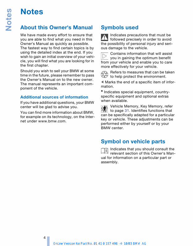
Symbols used
Indicates precautions that must be followed precisely in order to avoid
the possibility of personal injury and seri-ous damage to the vehicle.
Contains information that will assist you in gaining the optimum benefit
from your vehicle and enable you to care more effectively for your vehicle.
Refers to measures that can be taken to help protect the environment.
<
Marks the end of a specific item of infor-mation.
*
Indicates special equipment, country-specific equipment and optional extras when available.
Vehicle Memory, Key Memory, refer to page 31. Identifies functions that
can be specifically adapted for a particular key or vehicle. These adjustments can be performed either by yourself or by your BMW center.
Symbol on vehicle parts
Indicates that you should consult the relevant section of this Owner's Man-
ual for information on a particular part or assembly.
Refe
renc
eAt
a g
lanc
eCo
ntro
lsDr
ivin
g ti
psM
obili
ty
5
Your individual vehicle
On buying your BMW, you have decided in favor of a model with individualized equip-ment and features. This Owner's Manual describes all models and equipment that BMW offers within the same group.
We hope you will understand that equip-ment and features are included which you might not have chosen for your vehicle. Any differences can easily be identified since all optional accessories and special equip-ment are marked with an asterisk
*
.
If your BMW features equipment not described in this Owner's Manual, for example a car radio or telephone, supple-mentary Owner's Manuals are enclosed. We ask that you read these manuals as well.
Status of the Owner's Manual
BMW pursues a policy of continuous, ongoing development that is conceived to ensure that our vehicles continue to embody the highest quality and safety standards combined with advanced, state-of-the-art technology. For this reason, the features described in this Owner's Manual could differ from those on your vehicle. Nor can errors and omissions be entirely ruled out. You are therefore asked to appreciate that no claims can be entertained on the basis of the data, illustrations or descrip-tions in this manual.
For your own safety
Fuels
Use unleaded gasoline only. Fuels containing up to and including 10%
ethanol or other oxygenates with up to 2.8% oxygen by weight, i.e. 15% MTBE or 3% methanol plus an equivalent amount of co-solvent, will not void the applicable war-ranties respecting defects in materials or workmanship. Field experience has indi-cated significant differences in fuel quality, i.e. volatility, composition, additives, etc., among gasolines offered for sale in the United States and Canada. The use of poor quality fuels may result in driveability, start-ing and stalling problems especially under certain environmental conditions, such as high ambient temperature and high alti-tude.Should you encounter driveability prob-lems that you suspect could be related to the fuel you are using, we recommend that you respond by switching to a recognized high-quality brand.Failure to comply with these recommenda-tions may result in unscheduled mainte-nance.Follow the relevant safety rules when you are handling gasoline.
<
Maintenance and repair
Advanced technology, e.g. the use of modern materials and high-perfor-
mance electronics, requires specially adapted maintenance and repair methods. Therefore, only have corresponding work on your BMW carried out by a BMW center or a workshop that works according to BMW repair procedures with correspond-ingly trained personnel. If work is carried out improperly there is a danger of conse-quential damage and the related safety risks.
<

No
tes
6
Parts and accessories
For your own safety, use parts and accessories approved by BMW.
When you purchase accessories tested and approved by BMW and Original BMW Parts, you simultaneously acquire the assurance that they have been thoroughly tested by BMW to ensure optimum perfor-mance when installed on your vehicle. BMW warrants these parts to be free from defects in material and workmanship. BMW will not accept any liability for dam-age resulting from installation of parts and accessories not approved by BMW. BMW cannot test every product made by other manufacturers to verify if it can be used on a BMW safely and without risk to either the vehicle, its operation, or its occu-pants. Original BMW Parts, BMW Accessories and other products approved by BMW, together with professional advice on using these items, are available from all BMW retailers. Installation and operation of non-BMW approved accessories such as alarms, radios, amplifiers, radar detectors, wheels, suspension components, brake dust shields, telephones, including operation of any portable cellular phone from within the vehicle without using an externally mounted antenna, or transceiver equip-ment, e.g. C.B., walkie-talkie, ham radio or similar, may cause extensive damage to the vehicle, compromise its safety, inter-fere with the vehicle's electrical system or affect the validity of the BMW Limited War-ranty. See your BMW center for additional information. Do not use key or remote control to lock doors or trunk with anyone inside the vehi-cle. Refer to the Owner's Manual for more details.
<
Maintenance, replacement or repair of the emission control devices and
systems may be performed by any automo-tive repair establishment or individual using any certified automotive part.
<
Service and warranty
This manual is supplemented by a Service and Warranty Information Booklet for US models, Warranty and Service Guide Book-let for Canadian models.
We recommend that you read this publica-tion thoroughly.
Your BMW is covered by the following war-ranties:
>
New Vehicle Limited Warranty
>
Rust Perforation Limited Warranty
>
Federal Emissions System Defect War-ranty
>
Federal Emissions Performance War-ranty
>
California Emission Control System Limited Warranty.
Detailed information about these warran-ties is listed in the Service and Warranty Information Booklet for US models, War-ranty and Service Guide Booklet for Cana-dian models.
Refe
renc
eAt
a g
lanc
eCo
ntro
lsDr
ivin
g ti
psM
obili
ty
7
Reporting safety defects
The following only applies to vehicles owned and operated in the US.
If you believe that your vehicle has a defect which could cause a crash or could cause injury or death, you should immediately inform the National Highway Traffic Safety Administration NHTSA in addition to notifying BMW of North America, LLC, P.O. Box 1227, Westwood, New Jersey 07675-1227, telephone toll-free 1-800-831-1117.
If NHTSA receives similar complaints, it may open an investigation, and if it finds that a safety defect exists in a group of vehicles, it may order a recall and remedy campaign. However, NHTSA cannot become involved in individual problems between you, your retailer, or BMW of North America, LLC.
To contact NHTSA, you may either call the Auto Safety Hotline toll-free at 1-800-424-9393 or 366-0123 in Washington, D.C. area, or write to: NHTSA, U.S. Department of Transporta-tion, Washington, D.C. 20590. You can also obtain other information about motor vehi-cle safety from the Hotline.
At a glance
The overviews of buttons, switches anddisplays presented in this chapter will help
you find your way around your vehicle.You will also be familiarized with the con-cepts behind the operation of the features
available to you.

Co
ckp
it
10
Cockpit
Control elements
1
Parking lamps/Low beams 46
2
>
Turn signal indicators 43
>
Standing lamps 47
>
High beams 47
>
Headlamp flasher 43
>
Computer 50
3
Fog lamps 47
4
Horn
5
Washer/wiper system/Rain sensor 43
6
Hazard warning flashers
7
Central locking system 18
At a
gla
nce
Cont
rols
Driv
ing
tips
Mob
ility
Refe
renc
e
11
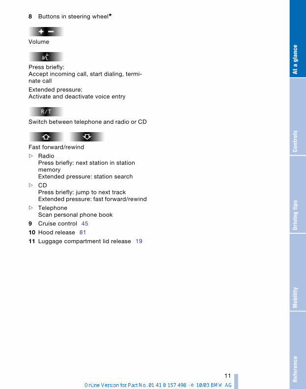
8
Buttons in steering wheel
*
Volume
Press briefly:Accept incoming call, start dialing, termi-nate call
Extended pressure:Activate and deactivate voice entry
Switch between telephone and radio or CD
Fast forward/rewind
>
RadioPress briefly: next station in station memoryExtended pressure: station search
>
CDPress briefly: jump to next trackExtended pressure: fast forward/rewind
>
TelephoneScan personal phone book
9
Cruise control 45
10
Hood release 81
11
Luggage compartment lid release 19
Co
ckp
it
12
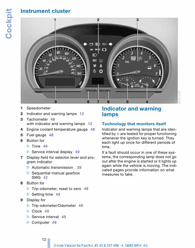
Instrument cluster
1
Speedometer
2
Indicator and warning lamps 12
3
Tachometer 48with indicator and warning lamps 12
4
Engine coolant temperature gauge 48
5
Fuel gauge 48
6
Button for
>
Time 49
> Service interval display 49
7 Display field for selector lever and pro-gram indicator
> Automatic transmission 39
> Sequential manual gearbox SMG 42
8 Button for
> Trip odometer, reset to zero 48
> Setting time 49
9 Display for
> Trip odometer/Odometer 48
> Clock 49
> Service interval 49
> Computer 49
Indicator and warning lamps
Technology that monitors itself Indicator and warning lamps that are iden-tified by + are tested for proper functioning whenever the ignition key is turned. They each light up once for different periods of time.
If a fault should occur in one of these sys-tems, the corresponding lamp does not go out after the engine is started or it lights up again while the vehicle is moving. The indi-cated pages provide information on what measures to take.
At a
gla
nce
Cont
rols
Driv
ing
tips
Mob
ility
Refe
renc
e
13
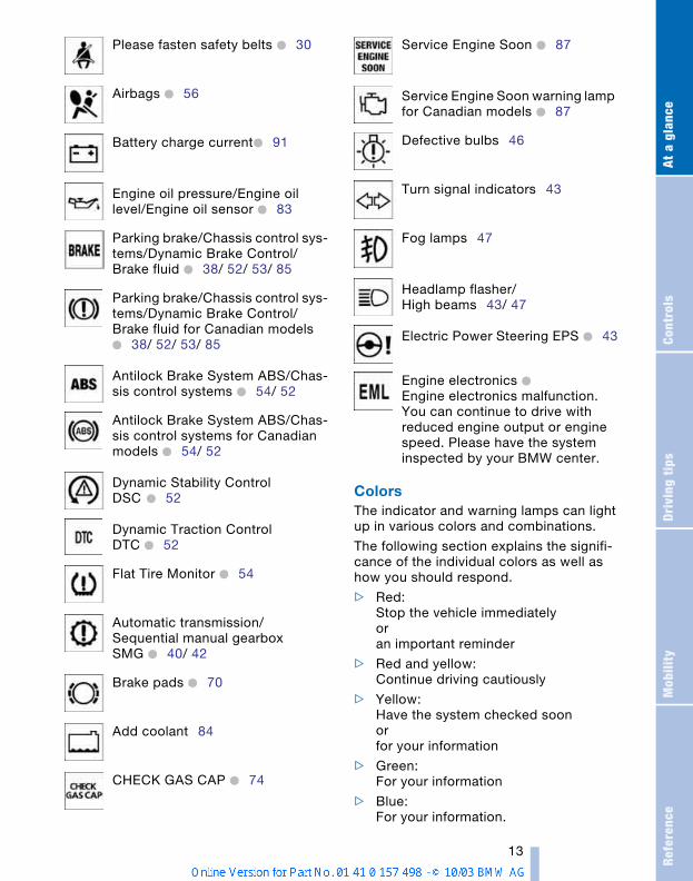
ColorsThe indicator and warning lamps can light up in various colors and combinations.
The following section explains the signifi-cance of the individual colors as well as how you should respond.
> Red: Stop the vehicle immediatelyoran important reminder
> Red and yellow:Continue driving cautiously
> Yellow:Have the system checked soonorfor your information
> Green:For your information
> Blue:For your information.
Please fasten safety belts + 30
Airbags + 56
Battery charge current+ 91
Engine oil pressure/Engine oil level/Engine oil sensor + 83
Parking brake/Chassis control sys-tems/Dynamic Brake Control/Brake fluid + 38/ 52/ 53/ 85
Parking brake/Chassis control sys-tems/Dynamic Brake Control/Brake fluid for Canadian models + 38/ 52/ 53/ 85
Antilock Brake System ABS/Chas-sis control systems + 54/ 52
Antilock Brake System ABS/Chas-sis control systems for Canadian models + 54/ 52
Dynamic Stability Control DSC + 52
Dynamic Traction Control DTC + 52
Flat Tire Monitor + 54
Automatic transmission/Sequential manual gearbox SMG + 40/ 42
Brake pads + 70
Add coolant 84
CHECK GAS CAP + 74
Service Engine Soon + 87
Service Engine Soon warning lamp for Canadian models + 87
Defective bulbs 46
Turn signal indicators 43
Fog lamps 47
Headlamp flasher/High beams 43/ 47
Electric Power Steering EPS + 43
Engine electronics + Engine electronics malfunction. You can continue to drive with reduced engine output or engine speed. Please have the system inspected by your BMW center.
ControlsThis chapter provides you with the informa-
tion you need for complete control overyour vehicle. It describes all features used
for driving and for ensuring your safety andcomfort.
Op
en
ing
an
d c
losi
ng
16
Opening and closing
Keys
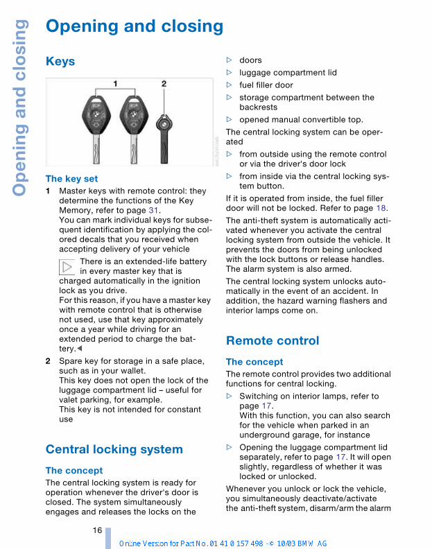
The key set1 Master keys with remote control: they
determine the functions of the Key Memory, refer to page 31.You can mark individual keys for subse-quent identification by applying the col-ored decals that you received when accepting delivery of your vehicle
There is an extended-life battery in every master key that is
charged automatically in the ignition lock as you drive.For this reason, if you have a master key with remote control that is otherwise not used, use that key approximately once a year while driving for an extended period to charge the bat-tery.<
2 Spare key for storage in a safe place, such as in your wallet.This key does not open the lock of the luggage compartment lid – useful for valet parking, for example.This key is not intended for constant use
Central locking system
The conceptThe central locking system is ready for operation whenever the driver's door is closed. The system simultaneously engages and releases the locks on the
> doors
> luggage compartment lid
> fuel filler door
> storage compartment between the backrests
> opened manual convertible top.
The central locking system can be oper-ated
> from outside using the remote control or via the driver's door lock
> from inside via the central locking sys-tem button.
If it is operated from inside, the fuel filler door will not be locked. Refer to page 18.
The anti-theft system is automatically acti-vated whenever you activate the central locking system from outside the vehicle. It prevents the doors from being unlocked with the lock buttons or release handles. The alarm system is also armed.
The central locking system unlocks auto-matically in the event of an accident. In addition, the hazard warning flashers and interior lamps come on.
Remote control
The conceptThe remote control provides two additional functions for central locking.
> Switching on interior lamps, refer to page 17.With this function, you can also search for the vehicle when parked in an underground garage, for instance
> Opening the luggage compartment lid separately, refer to page 17. It will open slightly, regardless of whether it was locked or unlocked.
Whenever you unlock or lock the vehicle, you simultaneously deactivate/activate the anti-theft system, disarm/arm the alarm
Refe
renc
eAt
a g
lanc
eCo
ntro
lsDr
ivin
g ti
psM
obili
ty
17
system and switch the interior lamps on/off.
You can have a signal set to confirm that the vehicle's locks have engaged
securely.<
Since persons or animals in the vehi-cle could lock the doors from the
inside, always take the vehicle keys with you so that the vehicle can be opened again from the outside at any time.<
If it is no longer possible to lock the vehicle via the remote control, the
battery is discharged. Use this key while driving for an extended period in order to recharge the battery.In the event of a system malfunction, please contact your BMW center. You can also obtain replacement keys there.<
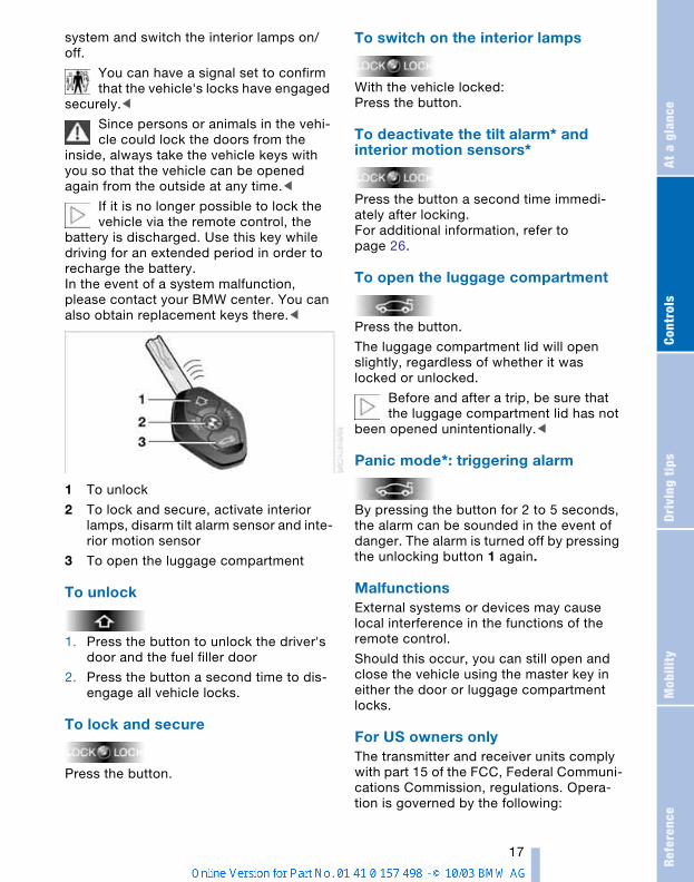
1 To unlock
2 To lock and secure, activate interior lamps, disarm tilt alarm sensor and inte-rior motion sensor
3 To open the luggage compartment
To unlock
1. Press the button to unlock the driver's door and the fuel filler door
2. Press the button a second time to dis-engage all vehicle locks.
To lock and secure
Press the button.
To switch on the interior lamps
With the vehicle locked:Press the button.
To deactivate the tilt alarm* and interior motion sensors*
Press the button a second time immedi-ately after locking.For additional information, refer to page 26.
To open the luggage compartment
Press the button.
The luggage compartment lid will open slightly, regardless of whether it was locked or unlocked.
Before and after a trip, be sure that the luggage compartment lid has not
been opened unintentionally.<
Panic mode*: triggering alarm
By pressing the button for 2 to 5 seconds, the alarm can be sounded in the event of danger. The alarm is turned off by pressing the unlocking button 1 again.
Malfunctions External systems or devices may cause local interference in the functions of the remote control.
Should this occur, you can still open and close the vehicle using the master key in either the door or luggage compartment locks.
For US owners onlyThe transmitter and receiver units comply with part 15 of the FCC, Federal Communi-cations Commission, regulations. Opera-tion is governed by the following:

Op
en
ing
an
d c
losi
ng
18
FCC ID: LX8EWS
LX8FZVS
LX8FZVE
Compliance statement:
This device complies with part 15 of the FCC Rules. Operation is subject to the fol-lowing two conditions:
> This device may not cause harmful interference, and
> this device must accept any interfer-ence received, including interference that may cause undesired operation.
Any unauthorized modifications to these devices could void the user's
authority to operate the equipment.<
Door lock
One turn of the key in the driver's door lock to unlock the driver's door only and the fuel filler door.
Turn the key a second time to disengage all other vehicle locks.
You can have a signal set to confirm that the vehicle's locks have engaged
securely.<
Convenience operation You can also operate the power windows and the fully automatic convertible top via the door lock.
> To open: With the door closed, hold the key in the Unlock position
> To close:With the door closed, hold the key in the Lock position.
Watch the closing process carefully and be sure that no one is trapped by
the closing motion. Releasing the key stops the operation.<
Manual operation In the event of an electrical malfunction
Turn the key all the way to the left or right to unlock/lock the driver's door.
Interior
You can use this button to control the cen-tral locking system whenever the doors are closed. The doors and luggage compart-ment lid are unlocked or locked only. The anti-theft system is not activated.
If only the driver's door was unlocked from the outside and you press the button, then, with the driver's door still open, the lug-gage compartment lid and the fuel filler door will unlock, too. If the driver's door is closed, it will be locked.
If you desire, the central locking sys-tem can be activated automatically as
soon as you begin to drive. This can be adjusted to be key-specific.<
To unlock and open > Either unlock the doors together with
the button for the central locking sys-tem and then pull each of the release handles above the armrests
or
> pull the release handle for each door twice: the initial pull unlocks the door, and the second one opens it.
Refe
renc
eAt
a g
lanc
eCo
ntro
lsDr
ivin
g ti
psM
obili
ty
19
To lock > Either use the central locking button to
lock both doors at once or
> press the individual door lock buttons down.
To prevent the driver from being inadvertently locked out of the
vehicle, the driver's door lock button will not engage as long as the door is open.<
Since persons or animals in the vehi-cle could lock the doors from the
inside, always take the vehicle keys with you so that the vehicle can be opened again from the outside at any time.<
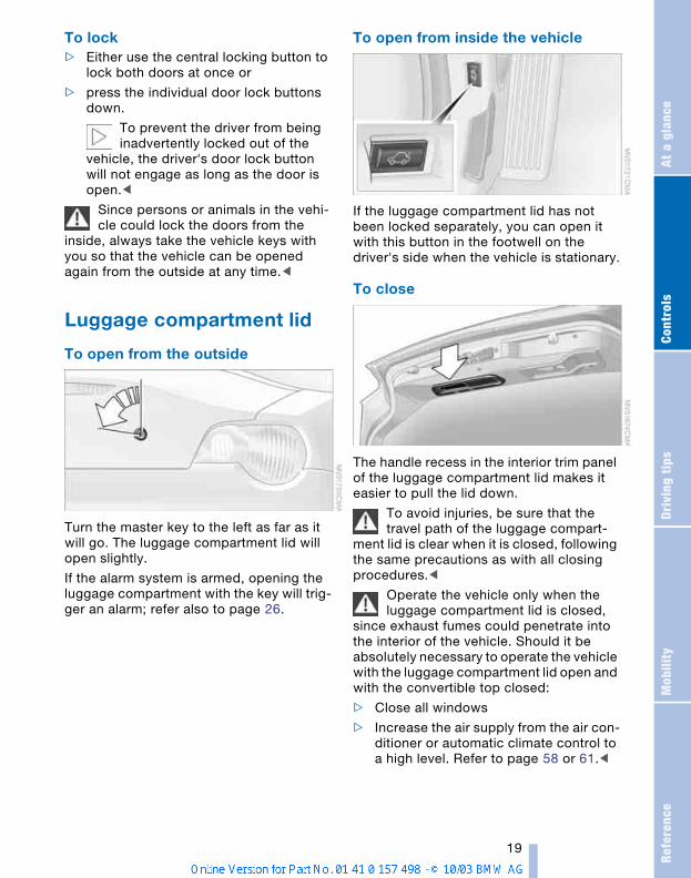
Luggage compartment lid
To open from the outside
Turn the master key to the left as far as it will go. The luggage compartment lid will open slightly.
If the alarm system is armed, opening the luggage compartment with the key will trig-ger an alarm; refer also to page 26.
To open from inside the vehicle
If the luggage compartment lid has not been locked separately, you can open it with this button in the footwell on the driver's side when the vehicle is stationary.
To close
The handle recess in the interior trim panel of the luggage compartment lid makes it easier to pull the lid down.
To avoid injuries, be sure that the travel path of the luggage compart-
ment lid is clear when it is closed, following the same precautions as with all closing procedures.<
Operate the vehicle only when the luggage compartment lid is closed,
since exhaust fumes could penetrate into the interior of the vehicle. Should it be absolutely necessary to operate the vehicle with the luggage compartment lid open and with the convertible top closed:
> Close all windows
> Increase the air supply from the air con-ditioner or automatic climate control to a high level. Refer to page 58 or 61.<
Op
en
ing
an
d c
losi
ng
20
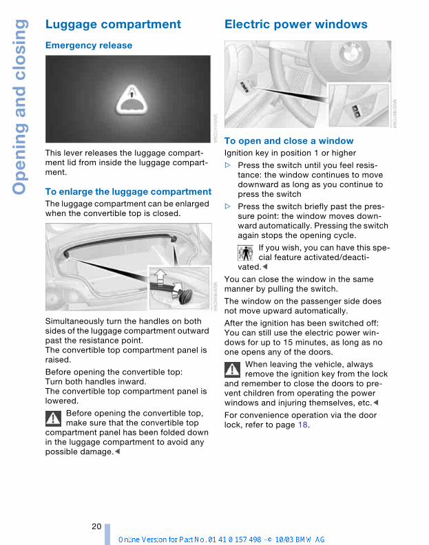
Luggage compartment
Emergency release
This lever releases the luggage compart-ment lid from inside the luggage compart-ment.
To enlarge the luggage compartmentThe luggage compartment can be enlarged when the convertible top is closed.
Simultaneously turn the handles on both sides of the luggage compartment outward past the resistance point.The convertible top compartment panel is raised.
Before opening the convertible top:Turn both handles inward.The convertible top compartment panel is lowered.
Before opening the convertible top, make sure that the convertible top
compartment panel has been folded down in the luggage compartment to avoid any possible damage.<
Electric power windows
To open and close a windowIgnition key in position 1 or higher
> Press the switch until you feel resis-tance: the window continues to move downward as long as you continue to press the switch
> Press the switch briefly past the pres-sure point: the window moves down-ward automatically. Pressing the switch again stops the opening cycle.
If you wish, you can have this spe-cial feature activated/deacti-
vated.<
You can close the window in the same manner by pulling the switch.
The window on the passenger side does not move upward automatically.
After the ignition has been switched off:You can still use the electric power win-dows for up to 15 minutes, as long as no one opens any of the doors.
When leaving the vehicle, always remove the ignition key from the lock
and remember to close the doors to pre-vent children from operating the power windows and injuring themselves, etc.<
For convenience operation via the door lock, refer to page 18.
Refe
renc
eAt
a g
lanc
eCo
ntro
lsDr
ivin
g ti
psM
obili
ty
21
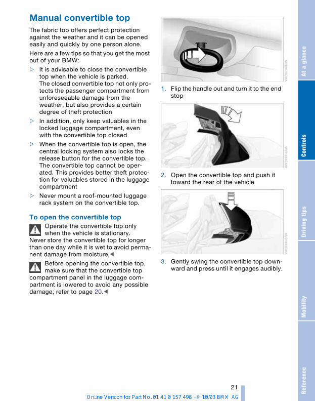
Manual convertible top The fabric top offers perfect protection against the weather and it can be opened easily and quickly by one person alone.
Here are a few tips so that you get the most out of your BMW:
> It is advisable to close the convertible top when the vehicle is parked.The closed convertible top not only pro-tects the passenger compartment from unforeseeable damage from the weather, but also provides a certain degree of theft protection
> In addition, only keep valuables in the locked luggage compartment, even with the convertible top closed
> When the convertible top is open, the central locking system also locks the release button for the convertible top. The convertible top cannot be oper-ated. This provides better theft protec-tion for valuables stored in the luggage compartment
> Never mount a roof-mounted luggage rack system on the convertible top.
To open the convertible topOperate the convertible top only when the vehicle is stationary.
Never store the convertible top for longer than one day while it is wet to avoid perma-nent damage from moisture.<
Before opening the convertible top, make sure that the convertible top
compartment panel in the luggage com-partment is lowered to avoid any possible damage; refer to page 20.<
1. Flip the handle out and turn it to the end stop
2. Open the convertible top and push it toward the rear of the vehicle
3. Gently swing the convertible top down-ward and press until it engages audibly.

Op
en
ing
an
d c
losi
ng
22
To close the convertible top
1. Press button 1 The convertible top is released and moves up slightly
2. Holding on to the handle, pull the con-vertible top forward onto the windshield frame
3. Turn the handle until it audibly engages. The convertible top is locked.
At higher speeds, the passenger compartment may develop relatively
low air pressure, which can cause the con-vertible top to begin fluttering. Increase the air supply so that low pressure does not occur in the vehicle.<
Fully automatic convertible top* The fully automatic convertible top com-bines assured protection against the ele-ments with simple and easy handling.
Here are a few tips so that you get the most out of your BMW:
> It is advisable to close the convertible top when the vehicle is parked. When closed, the top not only guards the pas-senger compartment from unforesee-able damage from the weather, but also affords a degree of protection against theft. In addition, only keep valuables in the locked luggage compartment, even with the convertible top closed
> Never mount a roof-mounted luggage rack system on the convertible top.
> To prevent damage, do not operate the convertible top at temperatures below 147/–106.
Never store the convertible top while it is wet to avoid permanent damage
from moisture. Driving when the opening or closing pro-cess has not been completed can cause vehicle damage or personal injury.Do not lay objects on the convertible top, since they could fall off when the convert-ible top is operated and cause damage or injuries.Do not reach into the convertible top mech-anism during opening and closing. Keep children away from the moving parts of the convertible top during operation.<
If possible, only operate the convert-ible top with the vehicle stopped, as
otherwise the process may be interrupted.If you set the convertible top in motion while the vehicle is stationary and then have to start suddenly, for instance at a traffic light, you can still complete the pro-cedure by driving as slowly as possible and again holding the corresponding button pressed.<
At higher speeds, the passenger compartment may develop relatively
low air pressure, which can cause the con-vertible top to begin fluttering. Increase the air supply so that low pressure does not occur in the vehicle.<
Opening and closing
1 To close
2 To open
If at all possible, only operate the con-vertible top if the engine is running.
This saves unnecessary battery wear.Before closing the convertible top, remove any objects from the windshield frame that
Refe
renc
eAt
a g
lanc
eCo
ntro
lsDr
ivin
g ti
psM
obili
ty
23
could keep the convertible top from closing properly.<
Ignition key in position 1 or higher. With the vehicle standing.
1. Read and comply with the preceding safety precautions
2. Make sure that the convertible top com-partment panel in the luggage compart-ment is lowered; refer to page 20. Oth-erwise the convertible top cannot be opened
3. Ensure that the luggage compartment lid is closed
4. Press and hold the corresponding but-ton for convertible top operation.
If the convertible top should halt right before the closing phase is completed, press against the front part of the convert-ible top frame from the outside to help the closing process along. Keep pressing the button while doing so until the top starts up again on its own.
Indicator lamps> The red indicator lamp in the button will
light up while the convertible top is in motion. It goes out as soon as the opening or closing operation has been completed
> If the red indicator lamp in the button flashes after the button has been released, then the opening or closing operation has not yet been completed. The sequence can be continued in the desired direction by pressing this but-ton
> If the yellow indicator lamp in the button lights up continuously with the button pressed, then the convertible top com-partment panel is raised and the con-vertible top cannot be moved.
The side windows will lower slightly when you press the button for operating the con-vertible top.
After the opening or closing operation, the side windows will go back up if you keep the button pressed for more than 2 sec-onds after the indicator lamp has gone out.
InterruptionThe automatic sequence will be interrupted immediately if you release the button that operates the top. The sequence can be continued in the desired direction by press-ing this button.
If the convertible top operation has been interrupted, do not close the
side windows using the power window but-tons. Otherwise the side windows may not close properly against the rubber seal of the convertible top.<
After the convertible top has been stored for an extended period of time
in the convertible top compartment, e.g. in the winter months because the hardtop was being used, you may have to support the convertible top by hand when closing it for the first time.<
Convenience operation
Driver's door lockRefer to page 18.
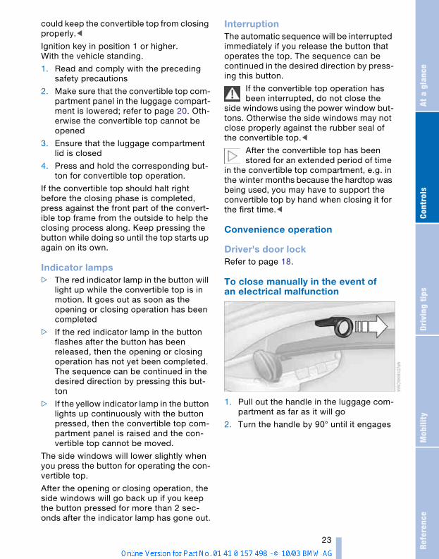
To close manually in the event of an electrical malfunction
1. Pull out the handle in the luggage com-partment as far as it will go
2. Turn the handle by 90° until it engages
Op
en
ing
an
d c
losi
ng
24
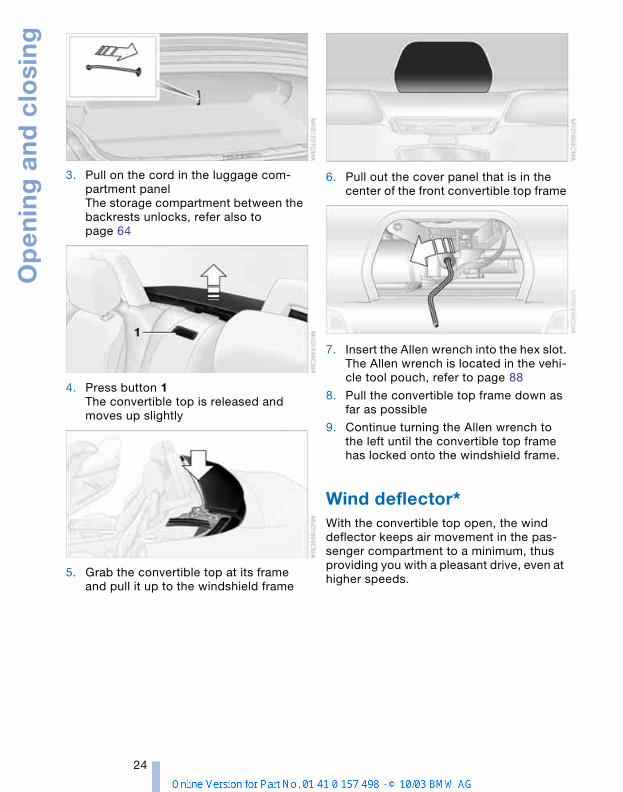
3. Pull on the cord in the luggage com-partment panelThe storage compartment between the backrests unlocks, refer also to page 64
4. Press button 1 The convertible top is released and moves up slightly
5. Grab the convertible top at its frame and pull it up to the windshield frame
6. Pull out the cover panel that is in the center of the front convertible top frame
7. Insert the Allen wrench into the hex slot.The Allen wrench is located in the vehi-cle tool pouch, refer to page 88
8. Pull the convertible top frame down as far as possible
9. Continue turning the Allen wrench to the left until the convertible top frame has locked onto the windshield frame.
Wind deflector* With the convertible top open, the wind deflector keeps air movement in the pas-senger compartment to a minimum, thus providing you with a pleasant drive, even at higher speeds.
Refe
renc
eAt
a g
lanc
eCo
ntro
lsDr
ivin
g ti
psM
obili
ty
25
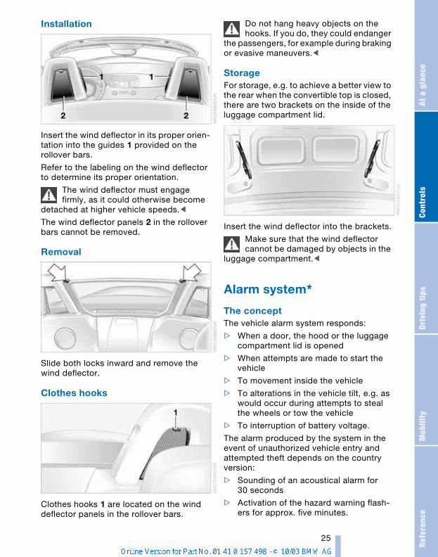
Installation
Insert the wind deflector in its proper orien-tation into the guides 1 provided on the rollover bars.
Refer to the labeling on the wind deflector to determine its proper orientation.
The wind deflector must engage firmly, as it could otherwise become
detached at higher vehicle speeds.<
The wind deflector panels 2 in the rollover bars cannot be removed.
Removal
Slide both locks inward and remove the wind deflector.
Clothes hooks
Clothes hooks 1 are located on the wind deflector panels in the rollover bars.
Do not hang heavy objects on the hooks. If you do, they could endanger
the passengers, for example during braking or evasive maneuvers.<
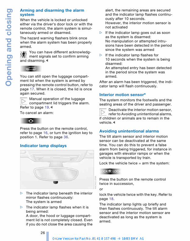
StorageFor storage, e.g. to achieve a better view to the rear when the convertible top is closed, there are two brackets on the inside of the luggage compartment lid.
Insert the wind deflector into the brackets.
Make sure that the wind deflector cannot be damaged by objects in the
luggage compartment.<
Alarm system*
The conceptThe vehicle alarm system responds:
> When a door, the hood or the luggage compartment lid is opened
> When attempts are made to start the vehicle
> To movement inside the vehicle
> To alterations in the vehicle tilt, e.g. as would occur during attempts to steal the wheels or tow the vehicle
> To interruption of battery voltage.
The alarm produced by the system in the event of unauthorized vehicle entry and attempted theft depends on the country version:
> Sounding of an acoustical alarm for 30 seconds
> Activation of the hazard warning flash-ers for approx. five minutes.
Op
en
ing
an
d c
losi
ng
26
Arming and disarming the alarm systemWhen the vehicle is locked or unlocked either via the driver's door lock or with the remote control, the alarm system is simul-taneously armed or disarmed.
The hazard warning flashers blink once when the alarm system has been properly armed.
You can have different acknowledg-ment signals set to confirm arming
and disarming.<
You can still open the luggage compart-ment lid when the system is armed by pressing the remote control button, refer to page 17. When it is closed, the lid is once again secured.
Manual operation of the luggage compartment lid triggers the alarm.
Refer to page 19.<
To cancel an alarm:
Press the button on the remote control, refer to page 16, or turn the ignition key to position 1. Refer to page 36.
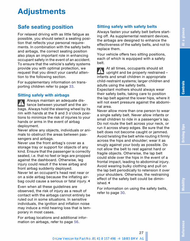
Indicator lamp displays
> The indicator lamp beneath the interior mirror flashes continuously:The system is armed
> The indicator lamp flashes when it is being armed: A door, the hood or luggage compart-ment lid is not completely closed. Even if you do not close the area causing the
alert, the remaining areas are secured and the indicator lamp flashes continu-ously after 10 seconds. However, the interior motion sensor is not activated
> If the indicator lamp goes out as soon as the system is disarmed: No manipulation or attempted intru-sions have been detected in the period since the system was armed
> If the indicator lamp flashes for 10 seconds when the system is being disarmed: An attempted entry has been detected in the period since the system was armed.
After an alarm has been triggered, the indi-cator lamp will flash continuously.
Interior motion sensor* The system monitors the footwells and the seating areas of the driver and passenger.
Deactivate the interior motion sensor, refer to Avoiding unintentional alarms,
if children or animals are to remain in the vehicle.<
Avoiding unintentional alarms The tilt alarm sensor and interior motion sensor can be deactivated at the same time. You can do this to prevent a false alarm from being triggered, for instance in garages with elevator ramps or when the vehicle is transported by train.
Lock the vehicle twice = arm the system:
Press the button on the remote control twice in succession,
or
lock the vehicle twice with the key. Refer to page 18.
The indicator lamp lights up briefly and then flashes continuously. The tilt alarm sensor and the interior motion sensor are deactivated as long as the system is armed.
Refe
renc
eAt
a g
lanc
eCo
ntro
lsDr
ivin
g ti
psM
obili
ty
27
Adjustments
Safe seating positionFor relaxed driving with as little fatigue as possible, you should select a seating posi-tion that reflects your personal require-ments. In combination with the safety belts and airbags, the correct seating position also plays an important role in enhancing occupant safety in the event of an accident. To ensure that the vehicle's safety systems provide you with optimal protection, we request that you direct your careful atten-tion to the following section.
For supplementary information on trans-porting children refer to page 33.
Sitting safely with airbags Always maintain an adequate dis-tance between yourself and the air-
bags. Always hold the steering wheel by its rim with hands at the 9 and 3 o'clock posi-tions to minimize the risk of injuries to your hands or arms in the event of airbag deployment.Never allow any objects, individuals or ani-mals to obstruct the areas between pas-sengers and airbags.Never use the front airbag's cover as a storage tray or support for objects of any kind. Ensure that the passenger is correctly seated, i.e. that no feet or legs are propped against the dashboard. Otherwise, leg injury could result if the knee airbag and front airbag suddenly deployed.Never let an occupant's head rest near or on a side airbag because the inflating air-bag could cause a serious or fatal injury.<
Even when all these guidelines are observed, the risk of injury as a result of contact with the airbags cannot entirely be ruled out in some situations. In sensitive individuals, the ignition and inflation noise may induce a mild hearing loss that is tem-porary in most cases.
For airbag locations and additional infor-mation on airbags, refer to page 56.
Sitting safely with safety belts Always fasten your safety belt before start-ing off. As supplemental restraint devices, the airbags are designed to enhance the effectiveness of the safety belts, and not to replace them.
Your vehicle offers two sitting positions, each of which is equipped with a safety belt.
At all times, occupants should sit upright and be properly restrained –
infants and small children in appropriate child-restraint systems; larger children and adults using the safety belts. Expectant mothers should always wear their safety belts, taking care to position the lap belt against the lower hips, where it will not exert pressure against the abdomi-nal area.Never allow more than one person to wear a single safety belt. Never allow infants or small children to ride in a passenger's lap. Do not route the belt across your neck, or run it across sharp edges. Be sure that the belt does not become caught or jammed. Avoid twisting the belt while routing it firmly across the hips and shoulder; wear it as snugly against your body as possible. Do not allow the belt to rest against hard or fragile objects. Otherwise, the lap belt could slide over the hips in the event of a frontal impact, leading to abdominal injury. Avoid wearing bulky clothing and pull on the lap belt periodically to retension it over your shoulders. Otherwise, the restraining effect of the safety belt could be dimin-ished.<
For information on using the safety belts, refer to page 30.
Ad
just
me
nts
28
Seats
Before adjusting your seat, always observe the following precautions
Never try to adjust your seat while operating the vehicle. The seat could
respond with an unexpected movement, and the ensuing loss of vehicle control could result in an accident. Never ride with the backrest inclined to an extreme angle – this also applies to the passenger seat. If you do so, there is a risk that you will slide under the safety belt in the event of an accident, thus reducing the protection provided by the safety belt.<
In addition, observe the instructions regarding damaged safety belts on page 30.
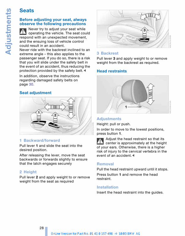
Seat adjustment
1 Backward/forwardPull lever 1 and slide the seat into the desired position.
After releasing the lever, move the seat backwards or forwards slightly to ensure that the latch engages securely
2 HeightPull lever 2 and apply weight to or remove weight from the seat as required
3 BackrestPull lever 3 and apply weight to or remove weight from the backrest as required.
Head restraints
Adjustments Height: pull or push.
In order to move to the lowest positions, press button 1.
Adjust the head restraint so that its center is approximately at the height
of your ears. Otherwise, there is a higher risk of injury to the cervical vertebra in the event of an accident.<
RemovalPull the head restraint upward until it stops.
Press button 1 and remove the head restraint.
InstallationInsert the head restraint into the guides.
Refe
renc
eAt
a g
lanc
eCo
ntro
lsDr
ivin
g ti
psM
obili
ty
29
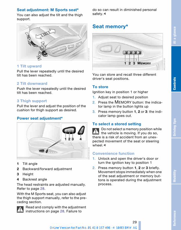
Seat adjustment: M Sports seat* You can also adjust the tilt and the thigh support.
1 Tilt upwardPull the lever repeatedly until the desired tilt has been reached.
2 Tilt downwardPush the lever repeatedly until the desired tilt has been reached.
3 Thigh supportPull the lever and adjust the position of the cushion for thigh support as desired.
Power seat adjustment*
1 Tilt angle
2 Backward/forward adjustment
3 Height
4 Backrest angle
The head restraints are adjusted manually. Refer to page 28.
With the M Sports seat, you can also adjust the thigh support manually, refer to the pre-ceding section.
Read and comply with the adjustment instructions on page 28. Failure to
do so can result in diminished personal safety.<
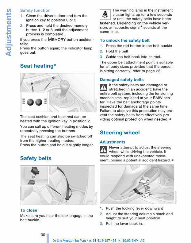
Seat memory*
You can store and recall three different driver's seat positions.
To storeIgnition key in position 1 or higher
1. Adjust seat to desired position
2. Press the MEMORY button: the indica-tor lamp in the button lights up
3. Press memory button 1, 2 or 3: the indi-cator lamp goes out.
To select a stored settingDo not select a memory position while the vehicle is moving. If you do so,
there is a risk of accident from an unex-pected movement of the seat or steering wheel.<
Convenience function1. Unlock and open the driver's door or
turn the ignition key to position 1
2. Press memory button 1, 2 or 3 briefly.Movement stops immediately when one of the seat adjustment or memory but-tons is operated during the adjustment process.
Ad
just
me
nts
30
Safety function1. Close the driver's door and turn the
ignition key to position 0 or 2
2. Press and hold the desired memory button 1, 2 or 3 until the adjustment process is completed.
If you press the MEMORY button acciden-tally: Press the button again; the indicator lamp goes out.
Seat heating*
The seat cushion and backrest can be heated with the ignition key in position 2.
You can call up different heating modes by repeatedly pressing the buttons.
The seat heating can also be switched off from the higher heating modes:Press the button and hold it slightly longer.
Safety belts
To closeMake sure you hear the lock engage in the belt buckle.
The warning lamp in the instrument cluster lights up for a few seconds or until the safety belts have been
fastened. Depending on the vehicle ver-sion, an acoustic signal* sounds at the same time.
To unlock the safety belt1. Press the red button in the belt buckle
2. Hold the belt
3. Guide the belt back into its reel.
The upper belt attachment point is suitable for all body sizes provided that the person is sitting correctly, refer to page 28.
Damaged safety beltsIf the safety belts are damaged or stretched in an accident: have the
entire belt system, including the tensioning mechanisms, replaced at your BMW cen-ter. Have the belt anchorage points inspected for damage at the same time. Failure to observe this precaution may pre-vent the safety belts from effectively pro-viding optimal protection when needed.<
Steering wheel
AdjustmentsNever attempt to adjust the steering wheel while driving the vehicle. It
could respond with unexpected move-ment, posing a potential accident hazard.<
1. Push the locking lever downward
2. Adjust the steering column's reach and height to suit your seat position
3. Pull the lever back in.
Refe
renc
eAt
a g
lanc
eCo
ntro
lsDr
ivin
g ti
psM
obili
ty
31
Mirrors
To adjust exterior mirrors
1 Switch for 4-way adjustment
2 Switch to select between mirrors
3 Button* for folding mirrors in and out
Fold the mirrors in and out by pressing the button repeatedly. This can be useful in car washes or narrow streets, for example, or for repositioning mirrors that have been folded forward.
The mirror can be folded in at driving speeds of up to 18.6 mph /
30 km/h.<
To adjust manuallyThe mirrors can also be adjusted manually:
Press on the edges of the lens.
Electric defrosting* Both mirrors are automatically heated in ignition key position 2.
Interior rearview mirror
To reduce the glare from vehicles behind you when driving at night, turn the rotary knob.
For vehicles without an alarm system: Tilt the small lever forward.
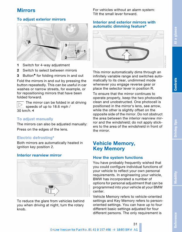
Interior and exterior mirrors with automatic dimming feature*
This mirror automatically dims through an infinitely variable range and switches auto-matically to its clear, undimmed mode whenever you engage reverse gear or place the selector lever in position R.
To ensure that the mirror continues to operate properly, keep the two photocells clean and unobstructed. One photocell is positioned in the mirror's lens, see arrow, while the other is slightly offset on the opposite side of the mirror. Do not obstruct the area between the interior rearview mir-ror and the windshield; do not apply stick-ers to the area of the windshield in front of the mirror.
Vehicle Memory, Key Memory
How the system functionsYou have probably frequently wished that you could configure individual functions of your vehicle to reflect your own personal requirements. In engineering your vehicle, BMW has incorporated a number of options for personal adjustment that can be programmed into your vehicle at your BMW center.
Vehicle Memory refers to vehicle-oriented settings and Key Memory refers to person-oriented settings. You can have up to four different basic settings adjusted for four different persons. The only requirement is
Ad
just
me
nts
32
that each person uses his or her own remote control key.
When your vehicle is unlocked with the remote control, the vehicle recognizes the individual user by means of a data exchange with the key, and makes adjust-ments accordingly.
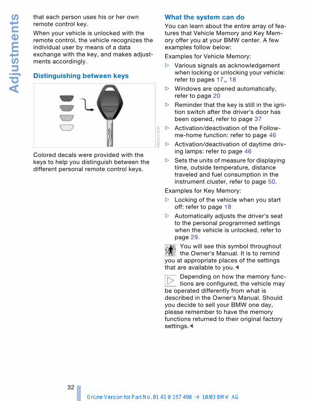
Distinguishing between keys
Colored decals were provided with the keys to help you distinguish between the different personal remote control keys.
What the system can doYou can learn about the entire array of fea-tures that Vehicle Memory and Key Mem-ory offer you at your BMW center. A few examples follow below:
Examples for Vehicle Memory:
> Various signals as acknowledgement when locking or unlocking your vehicle: refer to pages 17,, 18
> Windows are opened automatically, refer to page 20
> Reminder that the key is still in the igni-tion switch after the driver's door has been opened, refer to page 37
> Activation/deactivation of the Follow-me-home function: refer to page 46
> Activation/deactivation of daytime driv-ing lamps: refer to page 46
> Sets the units of measure for displaying time, outside temperature, distance traveled and fuel consumption in the instrument cluster, refer to page 50.
Examples for Key Memory:
> Locking of the vehicle when you start off: refer to page 18
> Automatically adjusts the driver's seat to the personal programmed settings when the vehicle is unlocked, refer to page 29.
You will see this symbol throughout the Owner's Manual. It is to remind
you at appropriate places of the settings that are available to you.<
Depending on how the memory func-tions are configured, the vehicle may
be operated differently from what is described in the Owner's Manual. Should you decide to sell your BMW one day, please remember to have the memory functions returned to their original factory settings.<
Refe
renc
eAt
a g
lanc
eCo
ntro
lsDr
ivin
g ti
psM
obili
ty
33
Transporting children safely
Children on the passenger's seat
Deactivating/reactivating passenger airbags
The passenger airbags must be deac-tivated before using a rear-facing
child-restraint system on the passenger seat, refer also to page 34 for explanation.BMW also recommends that the passenger airbags be deactivated if a child is trans-ported in a front-facing child-restraint sys-tem, regardless of the age of the child. If you transport a child in the passenger seat, not an infant in a rear-facing seat, who is properly seated and seat-belted at all times, the potential benefits of airbags deploying in an accident generally out-weigh the risks of the child being injured by the force of a deploying airbag. Therefore, you should deactivate the pas-senger airbags only if you find it difficult to ensure that the child will remain properly seated and seat-belted at all times.Always position the passenger seat as far back as possible and at the lowest level.The above warning and recommendations are compatible with regulations estab-lished by the National Highway Traffic Safety Administration, NHTSA, permitting the deactivation of passenger airbags by means of an on-off switch for members of certain at-risk groups.
Specifically, the at-risk groups are:
> Infants in rear-facing infant seats
> Persons with certain medical conditions
> Children aged 12 and under in the pas-senger seat.
NHTSA provides this information via their website, www.nhtsa.dot.gov, or via their Auto Safety Hotline toll-free at 1-800-424-9393 or 366-0123 in Washington, D.C. area.<
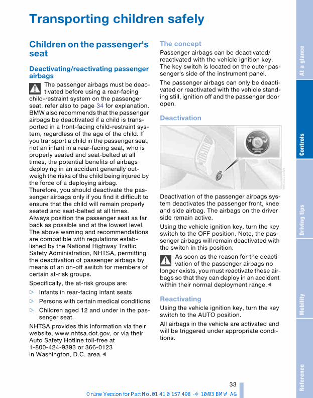
The conceptPassenger airbags can be deactivated/reactivated with the vehicle ignition key. The key switch is located on the outer pas-senger's side of the instrument panel.
The passenger airbags can only be deacti-vated or reactivated with the vehicle stand-ing still, ignition off and the passenger door open.
Deactivation
Deactivation of the passenger airbags sys-tem deactivates the passenger front, knee and side airbag. The airbags on the driver side remain active.
Using the vehicle ignition key, turn the key switch to the OFF position. Note, the pas-senger airbags will remain deactivated with the switch in this position.
As soon as the reason for the deacti-vation of the passenger airbags no
longer exists, you must reactivate these air-bags so that they can deploy in an accident within their normal deployment range.<
ReactivatingUsing the vehicle ignition key, turn the key switch to the AUTO position.
All airbags in the vehicle are activated and will be triggered under appropriate condi-tions.
Tra
nsp
ort
ing
ch
ildre
n s
afe
ly
34
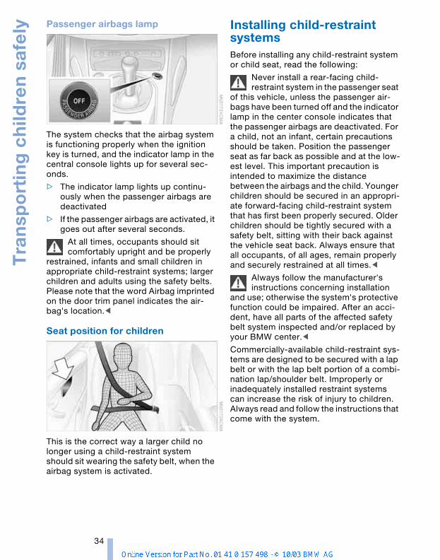
Passenger airbags lamp
The system checks that the airbag system is functioning properly when the ignition key is turned, and the indicator lamp in the central console lights up for several sec-onds.
> The indicator lamp lights up continu-ously when the passenger airbags are deactivated
> If the passenger airbags are activated, it goes out after several seconds.
At all times, occupants should sit comfortably upright and be properly
restrained, infants and small children in appropriate child-restraint systems; larger children and adults using the safety belts. Please note that the word Airbag imprinted on the door trim panel indicates the air-bag's location.<
Seat position for children
This is the correct way a larger child no longer using a child-restraint system should sit wearing the safety belt, when the airbag system is activated.
Installing child-restraint systemsBefore installing any child-restraint system or child seat, read the following:
Never install a rear-facing child-restraint system in the passenger seat
of this vehicle, unless the passenger air-bags have been turned off and the indicator lamp in the center console indicates that the passenger airbags are deactivated. For a child, not an infant, certain precautions should be taken. Position the passenger seat as far back as possible and at the low-est level. This important precaution is intended to maximize the distance between the airbags and the child. Younger children should be secured in an appropri-ate forward-facing child-restraint system that has first been properly secured. Older children should be tightly secured with a safety belt, sitting with their back against the vehicle seat back. Always ensure that all occupants, of all ages, remain properly and securely restrained at all times.<
Always follow the manufacturer's instructions concerning installation
and use; otherwise the system's protective function could be impaired. After an acci-dent, have all parts of the affected safety belt system inspected and/or replaced by your BMW center.<
Commercially-available child-restraint sys-tems are designed to be secured with a lap belt or with the lap belt portion of a combi-nation lap/shoulder belt. Improperly or inadequately installed restraint systems can increase the risk of injury to children. Always read and follow the instructions that come with the system.
Refe
renc
eAt
a g
lanc
eCo
ntro
lsDr
ivin
g ti
psM
obili
ty
35
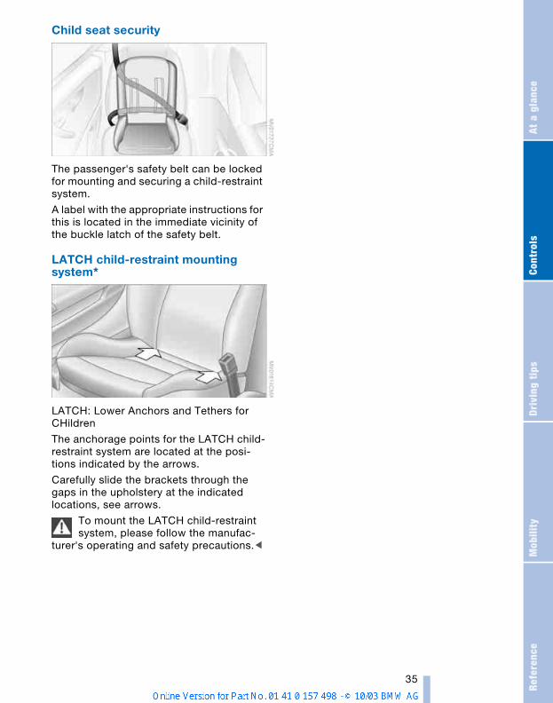
Child seat security
The passenger's safety belt can be locked for mounting and securing a child-restraint system.
A label with the appropriate instructions for this is located in the immediate vicinity of the buckle latch of the safety belt.
LATCH child-restraint mounting system*
LATCH: Lower Anchors and Tethers for CHildren
The anchorage points for the LATCH child-restraint system are located at the posi-tions indicated by the arrows.
Carefully slide the brackets through the gaps in the upholstery at the indicated locations, see arrows.
To mount the LATCH child-restraint system, please follow the manufac-
turer's operating and safety precautions.<
Dri
vin
g
36
Driving
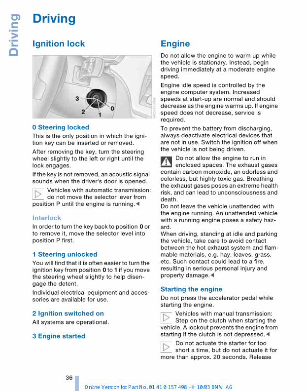
Ignition lock
0 Steering locked This is the only position in which the igni-tion key can be inserted or removed.
After removing the key, turn the steering wheel slightly to the left or right until the lock engages.
If the key is not removed, an acoustic signal sounds when the driver's door is opened.
Vehicles with automatic transmission:do not move the selector lever from
position P until the engine is running.<
InterlockIn order to turn the key back to position 0 or to remove it, move the selector level into position P first.
1 Steering unlocked You will find that it is often easier to turn the ignition key from position 0 to 1 if you move the steering wheel slightly to help disen-gage the detent.
Individual electrical equipment and acces-sories are available for use.
2 Ignition switched on All systems are operational.
3 Engine started
Engine Do not allow the engine to warm up while the vehicle is stationary. Instead, begin driving immediately at a moderate engine speed.
Engine idle speed is controlled by the engine computer system. Increased speeds at start-up are normal and should decrease as the engine warms up. If engine speed does not decrease, service is required.
To prevent the battery from discharging, always deactivate electrical devices that are not in use. Switch the ignition off when the vehicle is not being driven.
Do not allow the engine to run in enclosed spaces. The exhaust gases
contain carbon monoxide, an odorless and colorless, but highly toxic gas. Breathing the exhaust gases poses an extreme health risk, and can lead to unconsciousness and death. Do not leave the vehicle unattended with the engine running. An unattended vehicle with a running engine poses a safety haz-ard. When driving, standing at idle and parking the vehicle, take care to avoid contact between the hot exhaust system and flam-mable materials, e.g. hay, leaves, grass, etc. Such contact could lead to a fire, resulting in serious personal injury and property damage.<
Starting the engine Do not press the accelerator pedal while starting the engine.
Vehicles with manual transmission:Step on the clutch when starting the
vehicle. A lockout prevents the engine from starting if the clutch is not depressed.<
Do not actuate the starter for too short a time, but do not actuate it for
more than approx. 20 seconds. Release
Refe
renc
eAt
a g
lanc
eCo
ntro
lsDr
ivin
g ti
psM
obili
ty
37
the ignition key immediately when the engine starts.<
Extended starting attempts, charac-terized by excessively frequent or
long periods with the starter engaged, can damage the catalytic converter.<
If the engine fails to start on the first attempt, for instance if it is very hot or cold:
> Press the accelerator pedal halfway down.
Cold starts at very low temperatures, start-ing at approx. 57/–156:
> Press the accelerator pedal halfway down.
> On the first start attempt, engage the starter for a longer period, approx. 10 seconds.
Manual transmission1. Engage the parking brake
2. Gearshift lever in idling position
3. Depress clutch pedal
4. Start the engine.
Automatic transmission1. Depress footbrake
2. Place selector lever in position P or N
3. Start the engine.
Before leaving the vehicle with the engine running, place the selector
lever in position P and pull the parking brake.Do not leave the vehicle unattended with the engine running. An unattended vehicle with a running engine poses a safety haz-ard.<
Sequential manual gearbox SMG1. Depress footbrake
2. Move selector lever to neutral position N
3. Start the engine.
If the engine does not start, re-engage the gear last selected, refer to
the display in the instrument cluster, and
move the selector lever to neutral position N again.<
Before leaving the vehicle with the engine running, place the selector
lever in position N and pull the parking brake.Do not leave the vehicle unattended with the engine running. An unattended vehicle with a running engine poses a safety haz-ard.<
Switching off the engineDo not remove the ignition key while the vehicle is still moving. If you did
so, the steering lock would engage when the steering wheel is turned. When you leave the vehicle, always remove the ignition key and engage the steering lock.Always engage the parking brake when parking on downhill roads.<
You can have an acoustic signal set as a reminder that the ignition key is
still in the ignition switch after the driver's door has been opened.<
Manual transmissionTurn the ignition key to position 1 or 0.
Automatic transmissionPlace the selector lever in position P and turn the ignition key to position 1 or 0.
Sequential manual gearbox SMGIf you turn the ignition key to position 1 or 0 with the selector lever in position R, or in sequential mode, a gear automatically remains engaged.
If you turn the ignition key to position 1 or 0 with the selector lever in neutral position N, a warning tone and the flashing gear indi-cator in the display remind you that the vehicle is not secured against rolling.
The warning stops after approx. 9 seconds.
Always engage the parking brake when parking on downhill roads.
Engaging a gear may not sufficiently secure the vehicle against rolling.<
Dri
vin
g
38
Parking brake The parking brake is designed primarily to prevent the vehicle from rolling when parked. It operates against the rear wheels.
Indicator lampThe indicator lamp lights up when the parking brake is engaged; if you start driving, an acoustic signal is
heard as well.
The indicator lamp for Canadian models lights up when the parking brake is engaged; if you start driv-
ing, an acoustic signal is heard as well.
To engageThe detent engages automatically and the indicator lamp in the instrument cluster comes on when the ignition key is in posi-tion 2.
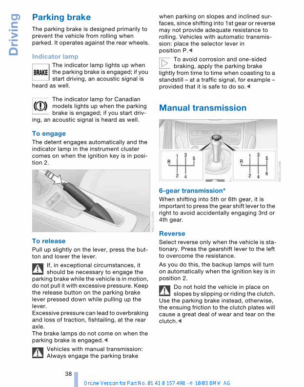
To releasePull up slightly on the lever, press the but-ton and lower the lever.
If, in exceptional circumstances, it should be necessary to engage the
parking brake while the vehicle is in motion, do not pull it with excessive pressure. Keep the release button on the parking brake lever pressed down while pulling up the lever.Excessive pressure can lead to overbraking and loss of traction, fishtailing, at the rear axle.The brake lamps do not come on when the parking brake is engaged.<
Vehicles with manual transmission:Always engage the parking brake
when parking on slopes and inclined sur-faces, since shifting into 1st gear or reverse may not provide adequate resistance to rolling. Vehicles with automatic transmis-sion: place the selector lever in position P.<
To avoid corrosion and one-sided braking, apply the parking brake
lightly from time to time when coasting to a standstill – at a traffic signal, for example – provided that it is safe to do so.<
Manual transmission
6-gear transmission*When shifting into 5th or 6th gear, it is important to press the gear shift lever to the right to avoid accidentally engaging 3rd or 4th gear.
Reverse Select reverse only when the vehicle is sta-tionary. Press the gearshift lever to the left to overcome the resistance.
As you do this, the backup lamps will turn on automatically when the ignition key is in position 2.
Do not hold the vehicle in place on slopes by slipping or riding the clutch.
Use the parking brake instead, otherwise, the ensuing friction to the clutch plates will cause a great deal of wear and tear on the clutch.<
Refe
renc
eAt
a g
lanc
eCo
ntro
lsDr
ivin
g ti
psM
obili
ty
39
Automatic transmission with Steptronic* You can drive as with a normal automatic transmission. In addition, you can also shift manually.
When you move the selector lever from the D position to the left into the M/S range, the performance-oriented shift programs of the automatic transmission are engaged. As soon as you briefly tap the selector lever in the + or — direction, Steptronic changes the gear. The manual mode is engaged. When you wish to use the automatic transmission mode again, move the selector lever to the right to position D.
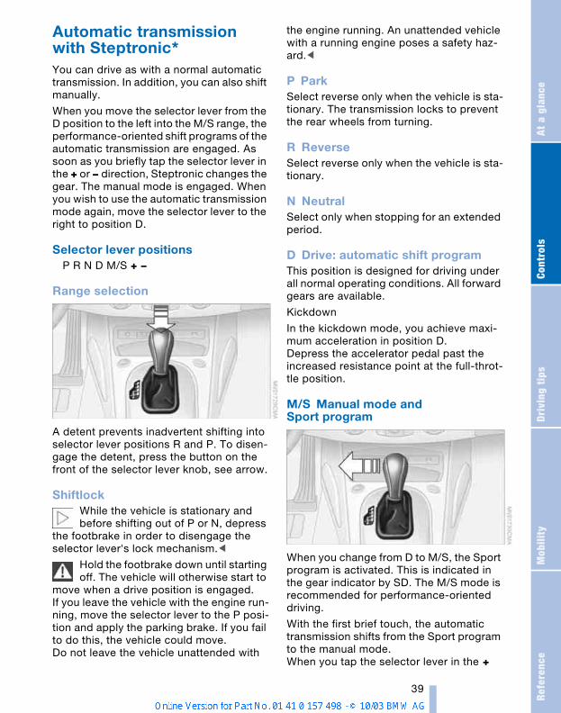
Selector lever positionsP R N D M/S + —
Range selection
A detent prevents inadvertent shifting into selector lever positions R and P. To disen-gage the detent, press the button on the front of the selector lever knob, see arrow.
ShiftlockWhile the vehicle is stationary and before shifting out of P or N, depress
the footbrake in order to disengage the selector lever's lock mechanism.<
Hold the footbrake down until starting off. The vehicle will otherwise start to
move when a drive position is engaged. If you leave the vehicle with the engine run-ning, move the selector lever to the P posi-tion and apply the parking brake. If you fail to do this, the vehicle could move.Do not leave the vehicle unattended with
the engine running. An unattended vehicle with a running engine poses a safety haz-ard.<
P ParkSelect reverse only when the vehicle is sta-tionary. The transmission locks to prevent the rear wheels from turning.
R ReverseSelect reverse only when the vehicle is sta-tionary.
N Neutral Select only when stopping for an extended period.
D Drive: automatic shift programThis position is designed for driving under all normal operating conditions. All forward gears are available.
Kickdown
In the kickdown mode, you achieve maxi-mum acceleration in position D.Depress the accelerator pedal past the increased resistance point at the full-throt-tle position.
M/S Manual mode and Sport program
When you change from D to M/S, the Sport program is activated. This is indicated in the gear indicator by SD. The M/S mode is recommended for performance-oriented driving.
With the first brief touch, the automatic transmission shifts from the Sport program to the manual mode.When you tap the selector lever in the +
Dri
vin
g
40
direction, the transmission shifts up. When the lever is tapped in the – direction, the transmission shifts down. M1 to M5 appear in the gear indicator.
The Adaptive Transmission Control ATC executes upshifts or downshifts only when the new gear will provide a suitable combi-nation of engine and road speed, e.g. ATC will not execute downshifts if the engine speed is too high. The desired gear will appear briefly in the instrument cluster, fol-lowed by the actual gear.
If you are driving in the manual mode and wish to accelerate rapidly, e.g. to
pass another vehicle, shift down manually or with the kickdown function.<
Shifting from M/S to selector lever posi-tions P, R and N is possible only by going through position D.
Available indicators
P R N D SD M1 M2 M3 M4 M5
Malfunction If the indicator lamp comes on, there is a malfunction in the trans-mission system.
All of the selector lever positions can con-tinue to be engaged; in the forward drive positions, however, the vehicle will be operating in the fourth gear only.
If this happens, avoid extreme engine loads and consult the nearest BMW center.
Never work in the engine compart-ment when a drive gear – forward or
reverse – is engaged. If you do so, the vehi-cle could move.<
For jump-starting or towing, refer to the information beginning on page 94.
Sequential manual gearbox SMG*
The conceptThe sequential manual gearbox SMG is an automated manual gearbox with which clutching and shifting is assumed by an electro-hydraulic system.
The SMG is operated via two shift paddles on the steering wheel and the selector lever in the center console.
It offers the following functions:
> Sequential mode: manual mode
> Drive mode: automated mode
> Ability to choose between two different driving programs: Standard, Sport, refer to Dynamic Driving Control
> Operating safety through protection against misshifting
> Automatic upshifts and downshifts in the drive mode
> Automatic downshifts at minimum engine rpm
> Kickdown function in the drive mode
> Acceleration assistant.
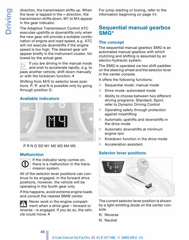
Selector lever positions
The current selector lever position is shown by a light-emitting diode on the center con-sole.
R: Reverse
N: Neutral
Refe
renc
eAt
a g
lanc
eCo
ntro
lsDr
ivin
g ti
psM
obili
ty
41
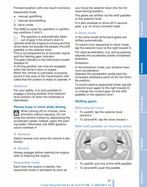
Forward position with one-touch functions:
Sequential mode
+: manual upshifting
—: manual downshifting
D: drive mode.
The SMG is ready for operation in ignition key positions 2 and 3.
The gearbox is automatically taken out of gear if the driver's door is
opened while the engine is running and the driver does not actuate the pedals, the shift paddles or the selector lever. This is accompanied by an acoustic signal and the flashing gear indicator. The gear indicator in the instrument cluster displays N. A driving position can only be engaged when the driver's door is closed. When the vehicle is unlocked, a buzzing sound in the area of the transmission indi-cates that the system is ready to operate.<
ShiftlockFor your safety, it is only possible to engage a driving position from selector lever position N when the footbrake is depressed.
Please keep in mind while drivingWhen driving off on inclines, drive smoothly without pausing. Do not
keep the vehicle in place by depressing the accelerator pedal; instead, apply the park-ing brake. Otherwise, the SMG gearbox could overheat.<
R ReverseSelect reverse only when the vehicle is sta-tionary.
N NeutralAlways engage before starting the engine, refer to Starting the engine.
Sequential modeEach time the engine is started, the sequential mode is activated as soon as
you move the selector lever into the for-ward driving position.
The gears are shifted via the shift paddles or the selector lever.
It is also possible to drive off in second gear, e.g. on snow-covered roads.
D Drive modeIn the drive mode all forward gears are shifted automatically.
To switch from sequential to drive mode: tap the selector lever to the right toward D.
For rapid acceleration, e.g. during passing, depress the accelerator pedal completely: kickdown.
Kickdown:
In the kickdown mode, you achieve maxi-mum acceleration.Depress the accelerator pedal past the increased resistance point at the full-throt-tle position.
To switch back to sequential mode: tap the selector lever again to the right toward D, or change the current gear via the shift paddles or the selector lever.
Shifting gears
With selector lever> To upshift, tap the selector lever
toward +
> To downshift, tap the lever toward —.
With shift paddles on steering wheel
> To upshift, pull one of the shift paddles
> To downshift, push the paddle.
Dri
vin
g
42
You accelerate from higher gears, e.g. dur-ing passing, by downshifting manually.
In the following situations, the SMG in the sequential mode assists you:
> The transmission will only execute upshifts and downshifts that will result in an appropriate combination of vehi-cle speed and engine rpm. For instance, downshifts that would result in excessive engine speed cannot be executed
> During a stop the gearbox is automati-cally downshifted into first gear
> Shortly before a gear-dependent mini-mum speed is reached, the gearbox shifts down automatically without you taking any action.
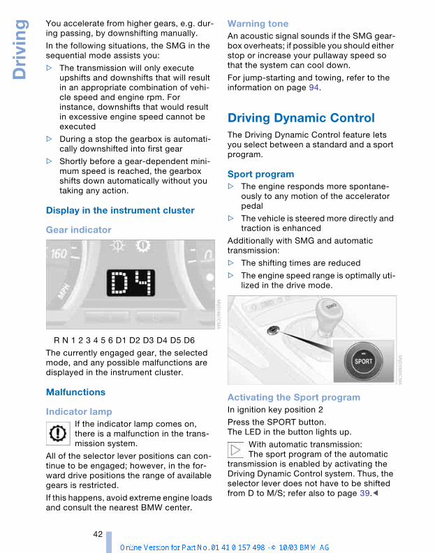
Display in the instrument cluster
Gear indicator
R N 1 2 3 4 5 6 D1 D2 D3 D4 D5 D6
The currently engaged gear, the selected mode, and any possible malfunctions are displayed in the instrument cluster.
Malfunctions
Indicator lampIf the indicator lamp comes on, there is a malfunction in the trans-mission system.
All of the selector lever positions can con-tinue to be engaged; however, in the for-ward drive positions the range of available gears is restricted.
If this happens, avoid extreme engine loads and consult the nearest BMW center.
Warning toneAn acoustic signal sounds if the SMG gear-box overheats; if possible you should either stop or increase your pullaway speed so that the system can cool down.
For jump-starting and towing, refer to the information on page 94.
Driving Dynamic ControlThe Driving Dynamic Control feature lets you select between a standard and a sport program.
Sport program > The engine responds more spontane-
ously to any motion of the accelerator pedal
> The vehicle is steered more directly and traction is enhanced
Additionally with SMG and automatic transmission:
> The shifting times are reduced
> The engine speed range is optimally uti-lized in the drive mode.
Activating the Sport programIn ignition key position 2
Press the SPORT button.The LED in the button lights up.
With automatic transmission:The sport program of the automatic
transmission is enabled by activating the Driving Dynamic Control system. Thus, the selector lever does not have to be shifted from D to M/S; refer also to page 39.<
Refe
renc
eAt
a g
lanc
eCo
ntro
lsDr
ivin
g ti
psM
obili
ty
43
Deactivating the Sport programPress the SPORT button again.The LED in the button goes out.
Acceleration assistant with SMGThe acceleration assistant permits opti-mum racing-style acceleration on skid-resistant roads.
Do not use the acceleration assistant too often, as this could cause the
vehicle's parts to wear prematurely.<
1. Activate the Sport program
2. Press and hold the DSC button for more than three seconds, refer to page 53
3. Depress the accelerator all the way down rapidly: kickdown. The optimum rpm for driving off will be adjusted.
To maintain vehicle stability, drive with the DSC switched on whenever
possible.<
Electric Power Steering EPS
The conceptThe electric power steering is a direct, sporting steering system that is speed-sen-sitive. Power support is reduced with an increase in driving speed.
Indicator lampThe indicator lamp stays lit:The system has malfunctioned or is faulty.
Please have the system inspected by the nearest BMW center. Steering remains operational.
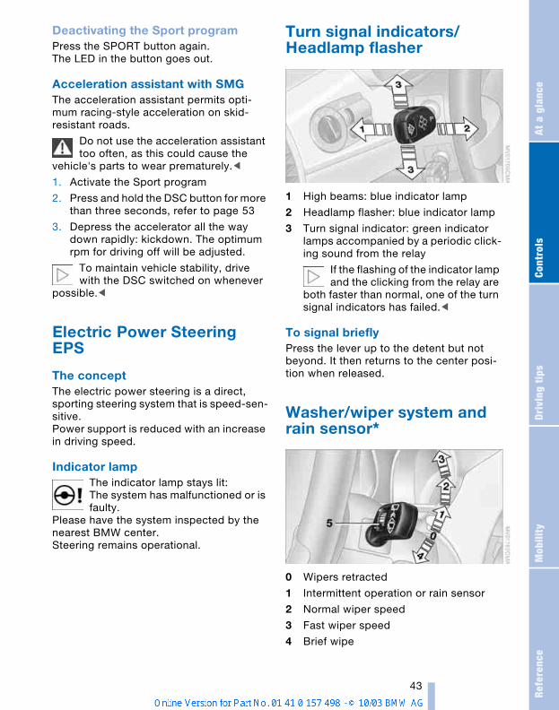
Turn signal indicators/Headlamp flasher
1 High beams: blue indicator lamp
2 Headlamp flasher: blue indicator lamp
3 Turn signal indicator: green indicator lamps accompanied by a periodic click-ing sound from the relay
If the flashing of the indicator lamp and the clicking from the relay are
both faster than normal, one of the turn signal indicators has failed.<
To signal brieflyPress the lever up to the detent but not beyond. It then returns to the center posi-tion when released.
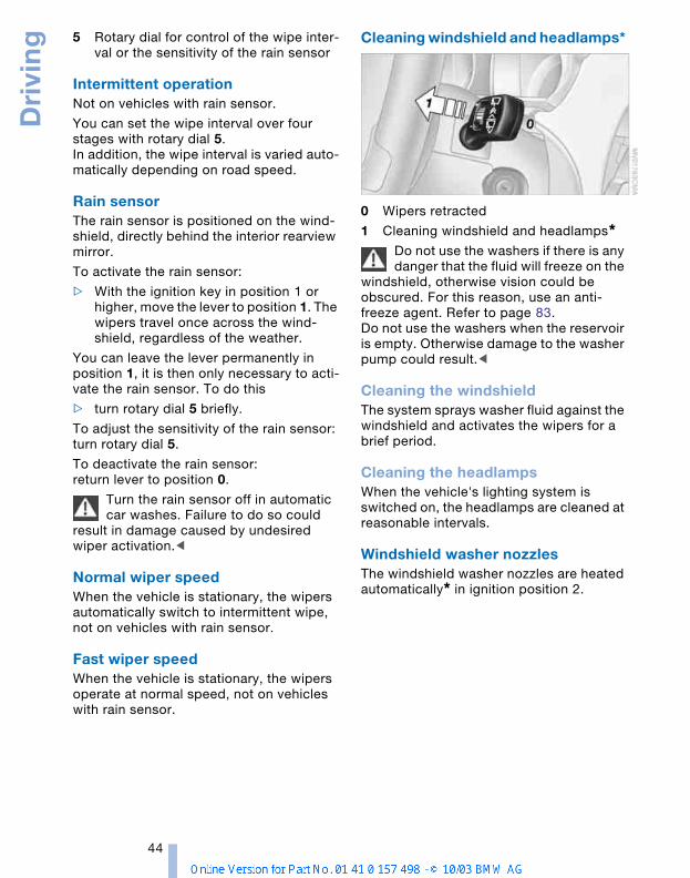
Washer/wiper system and rain sensor*
0 Wipers retracted
1 Intermittent operation or rain sensor
2 Normal wiper speed
3 Fast wiper speed
4 Brief wipe
Dri
vin
g
44
5 Rotary dial for control of the wipe inter-val or the sensitivity of the rain sensor
Intermittent operationNot on vehicles with rain sensor.
You can set the wipe interval over four stages with rotary dial 5.In addition, the wipe interval is varied auto-matically depending on road speed.
Rain sensor The rain sensor is positioned on the wind-shield, directly behind the interior rearview mirror.
To activate the rain sensor:
> With the ignition key in position 1 or higher, move the lever to position 1. The wipers travel once across the wind-shield, regardless of the weather.
You can leave the lever permanently in position 1, it is then only necessary to acti-vate the rain sensor. To do this
> turn rotary dial 5 briefly.
To adjust the sensitivity of the rain sensor: turn rotary dial 5.
To deactivate the rain sensor:return lever to position 0.
Turn the rain sensor off in automatic car washes. Failure to do so could
result in damage caused by undesired wiper activation.<
Normal wiper speedWhen the vehicle is stationary, the wipers automatically switch to intermittent wipe, not on vehicles with rain sensor.
Fast wiper speedWhen the vehicle is stationary, the wipers operate at normal speed, not on vehicles with rain sensor.
Cleaning windshield and headlamps*
0 Wipers retracted
1 Cleaning windshield and headlamps*Do not use the washers if there is any danger that the fluid will freeze on the
windshield, otherwise vision could be obscured. For this reason, use an anti-freeze agent. Refer to page 83.Do not use the washers when the reservoir is empty. Otherwise damage to the washer pump could result.<
Cleaning the windshield The system sprays washer fluid against the windshield and activates the wipers for a brief period.
Cleaning the headlamps When the vehicle's lighting system is switched on, the headlamps are cleaned at reasonable intervals.
Windshield washer nozzlesThe windshield washer nozzles are heated automatically* in ignition position 2.
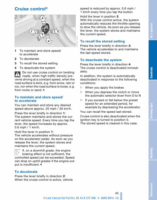
Refe
renc
eAt
a g
lanc
eCo
ntro
lsDr
ivin
g ti
psM
obili
ty
45
Cruise control*
1 To maintain and store speed/to accelerate
2 To decelerate
3 To recall the stored setting
4 To deactivate the system
Do not use cruise control on twisting roads, when high traffic density pre-
vents driving at a constant speed, when the road surface is slick, e.g. from snow, rain or ice, nor when the road surface is loose, e.g. from rocks or sand.<
To maintain and store speed/to accelerateYou can maintain and store any desired speed above approx. 20 mph / 30 km/h.
Press the lever briefly in direction 1:The system maintains and stores the cur-rent vehicle speed. Every time you tap the lever, the speed increases by approx. 0.6 mph / 1 km/h.
Hold the lever in position 1:The vehicle accelerates without pressure on the accelerator pedal. As soon as you release the lever, the system stores and maintains the current speed.
If, on a downhill grade, the engine braking effect is not sufficient, the
controlled speed can be exceeded. Speed can drop on uphill grades if the engine out-put is insufficient.<
To deceleratePress the lever briefly in direction 2:When the cruise control is active, vehicle
speed is reduced by approx. 0.6 mph / 1 km/h every time you tap the button.
Hold the lever in position 2:With the cruise control active, the system automatically reduces the throttle opening to slow the vehicle. As soon as you release the lever, the system stores and maintains the current speed.
To recall the stored settingPress the lever briefly in direction 3:The vehicle accelerates to and maintains the last speed stored.
To deactivate the system Press the lever briefly in direction 4:The cruise control is deactivated immedi-ately.
In addition, the system is automatically deactivated in response to the following conditions:
> When you apply the brakes
> When you depress the clutch or move the automatic selector lever from D to N
> If you exceed or fall below the preset speed for an extended period, for example by depressing the accelerator.
You can recall the speed last stored.
Cruise control is also deactivated when the ignition key is turned to position 0.The stored speed is cleared in this case.
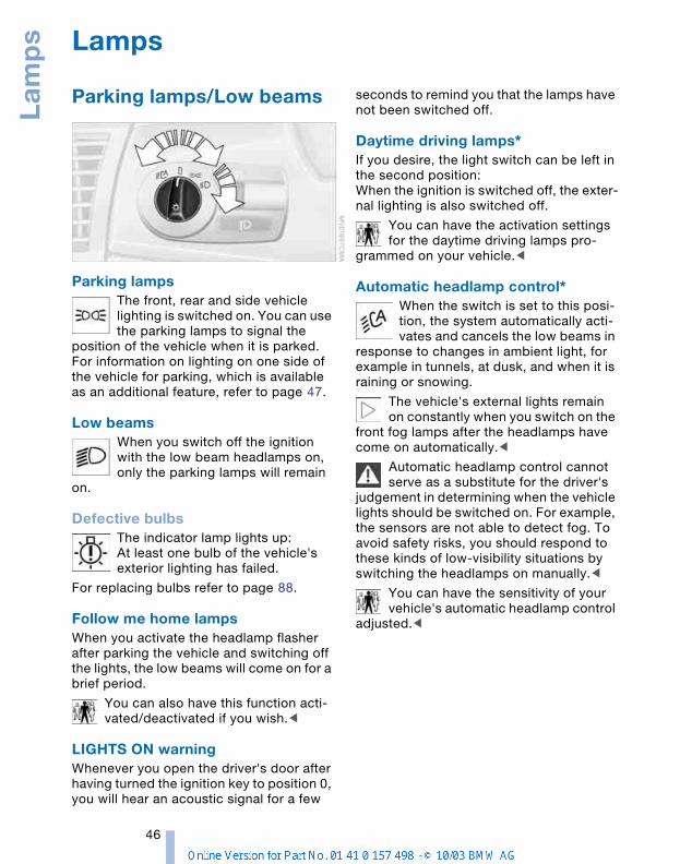
Lam
ps
46
Lamps
Parking lamps/Low beams
Parking lamps The front, rear and side vehicle lighting is switched on. You can use the parking lamps to signal the
position of the vehicle when it is parked. For information on lighting on one side of the vehicle for parking, which is available as an additional feature, refer to page 47.
Low beamsWhen you switch off the ignition with the low beam headlamps on, only the parking lamps will remain
on.
Defective bulbsThe indicator lamp lights up:At least one bulb of the vehicle's exterior lighting has failed.
For replacing bulbs refer to page 88.
Follow me home lamps When you activate the headlamp flasher after parking the vehicle and switching off the lights, the low beams will come on for a brief period.
You can also have this function acti-vated/deactivated if you wish.<
LIGHTS ON warning Whenever you open the driver's door after having turned the ignition key to position 0, you will hear an acoustic signal for a few
seconds to remind you that the lamps have not been switched off.
Daytime driving lamps* If you desire, the light switch can be left in the second position: When the ignition is switched off, the exter-nal lighting is also switched off.
You can have the activation settings for the daytime driving lamps pro-
grammed on your vehicle.<
Automatic headlamp control* When the switch is set to this posi-tion, the system automatically acti-vates and cancels the low beams in
response to changes in ambient light, for example in tunnels, at dusk, and when it is raining or snowing.
The vehicle's external lights remain on constantly when you switch on the
front fog lamps after the headlamps have come on automatically.<
Automatic headlamp control cannot serve as a substitute for the driver's
judgement in determining when the vehicle lights should be switched on. For example, the sensors are not able to detect fog. To avoid safety risks, you should respond to these kinds of low-visibility situations by switching the headlamps on manually.<
You can have the sensitivity of your vehicle's automatic headlamp control
adjusted.<
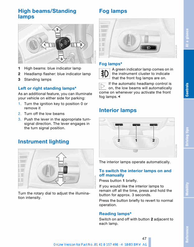
Refe
renc
eAt
a g
lanc
eCo
ntro
lsDr
ivin
g ti
psM
obili
ty
47
High beams/Standing lamps
1 High beams: blue indicator lamp
2 Headlamp flasher: blue indicator lamp
3 Standing lamps
Left or right standing lamps*As an additional feature, you can illuminate your vehicle on either side for parking:
1. Turn the ignition key to position 0 or remove it
2. Turn off the low beams
3. Push the lever in the appropriate turn-signal direction. The lever engages in the turn signal position.
Instrument lighting
Turn the rotary dial to adjust the illumina-tion intensity.
Fog lamps
Fog lamps* A green indicator lamp comes on in the instrument cluster to indicate that the front fog lamps are on.
If the automatic headlamp control is on, the low beams will automatically
come on whenever you activate the front fog lamps.<
Interior lamps
The interior lamps operate automatically.
To switch the interior lamps on and off manuallyPress button 1 briefly.
If you would like the interior lamps to remain off all the time, press and hold the button for approx. 3 seconds.
Press the button briefly to revert to normal operation.
Reading lamps* Switch on and off with button 2 adjacent to each lamp.
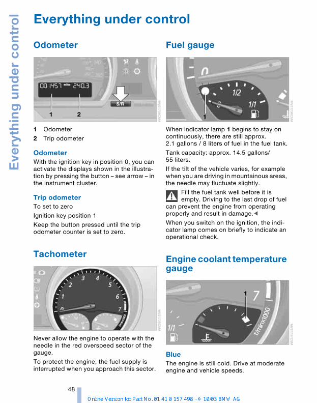
Eve
ryth
ing
un
de
r c
on
tro
l
48
Everything under control
Odometer
1 Odometer
2 Trip odometer
Odometer With the ignition key in position 0, you can activate the displays shown in the illustra-tion by pressing the button – see arrow – in the instrument cluster.
Trip odometer To set to zero
Ignition key position 1
Keep the button pressed until the trip odometer counter is set to zero.
Tachometer
Never allow the engine to operate with the needle in the red overspeed sector of the gauge.
To protect the engine, the fuel supply is interrupted when you approach this sector.
Fuel gauge
When indicator lamp 1 begins to stay on continuously, there are still approx. 2.1 gallons / 8 liters of fuel in the fuel tank.
Tank capacity: approx. 14.5 gallons/55 liters.
If the tilt of the vehicle varies, for example when you are driving in mountainous areas, the needle may fluctuate slightly.
Fill the fuel tank well before it is empty. Driving to the last drop of fuel
can prevent the engine from operating properly and result in damage.<
When you switch on the ignition, the indi-cator lamp comes on briefly to indicate an operational check.
Engine coolant temperature gauge
BlueThe engine is still cold. Drive at moderate engine and vehicle speeds.
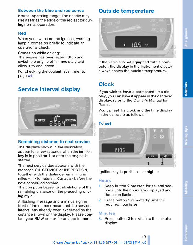
Refe
renc
eAt
a g
lanc
eCo
ntro
lsDr
ivin
g ti
psM
obili
ty
49
Between the blue and red zonesNormal operating range. The needle may rise as far as the edge of the red sector dur-ing normal operation.
RedWhen you switch on the ignition, warning lamp 1 comes on briefly to indicate an operational check.
Comes on while driving: The engine has overheated. Stop and switch the engine off immediately and allow it to cool down.
For checking the coolant level, refer to page 84.
Service interval display
Remaining distance to next service The displays shown in the illustration appear for a few seconds when the ignition key is in position 1 or after the engine is started.
The next service due appears with the message OIL SERVICE or INSPECTION, together with the distance remaining in miles – in kilometers in Canada – before the next scheduled service.The computer bases its calculations of the remaining distance on the preceding driv-ing style.
A flashing message and a minus sign in front of the number mean that the service interval has already been exceeded by the distance shown on the display. Please con-tact your BMW center for an appointment.
Outside temperature
If the vehicle is not equipped with a com-puter, the display in the instrument cluster always shows the outside temperature.
Clock If you wish to have a permanent time dis-play, you can have it appear in the car radio display, refer to the Owner's Manual for Radio.
You can set the clock and the time display in the car radio as follows.
To set
Ignition key in position 1 or higher:
Hours1. Keep button 2 pressed for several sec-
onds until the hours are displayed and the colon flashes
2. Press button 1 repeatedly until the required hour is set
Minutes3. Press button 2 to switch to the minutes
display
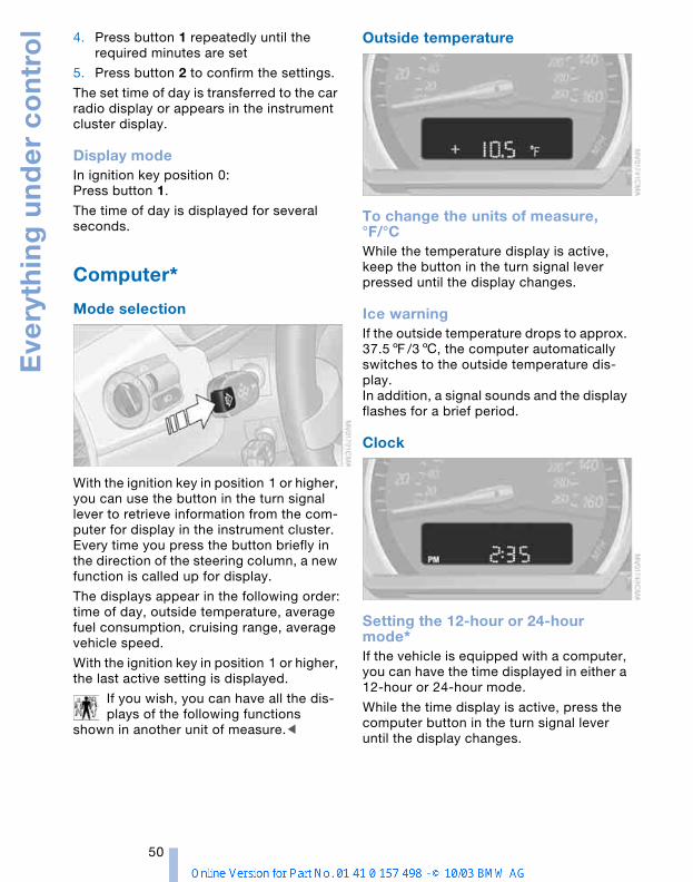
Eve
ryth
ing
un
de
r c
on
tro
l
50
4. Press button 1 repeatedly until the required minutes are set
5. Press button 2 to confirm the settings.
The set time of day is transferred to the car radio display or appears in the instrument cluster display.
Display modeIn ignition key position 0: Press button 1.
The time of day is displayed for several seconds.
Computer*
Mode selection
With the ignition key in position 1 or higher, you can use the button in the turn signal lever to retrieve information from the com-puter for display in the instrument cluster. Every time you press the button briefly in the direction of the steering column, a new function is called up for display.
The displays appear in the following order:time of day, outside temperature, average fuel consumption, cruising range, average vehicle speed.
With the ignition key in position 1 or higher, the last active setting is displayed.
If you wish, you can have all the dis-plays of the following functions
shown in another unit of measure.<
Outside temperature
To change the units of measure, °F/°C While the temperature display is active, keep the button in the turn signal lever pressed until the display changes.
Ice warningIf the outside temperature drops to approx. 37.57/36, the computer automatically switches to the outside temperature dis-play. In addition, a signal sounds and the display flashes for a brief period.
Clock
Setting the 12-hour or 24-hour mode* If the vehicle is equipped with a computer, you can have the time displayed in either a 12-hour or 24-hour mode.
While the time display is active, press the computer button in the turn signal lever until the display changes.
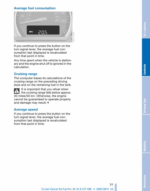
Refe
renc
eAt
a g
lanc
eCo
ntro
lsDr
ivin
g ti
psM
obili
ty
51
Average fuel consumption
If you continue to press the button on the turn signal lever, the average fuel con-sumption last displayed is recalculated from that point in time.
Any time spent when the vehicle is station-ary and the engine shut off is ignored in the calculation.
Cruising rangeThe computer bases its calculations of the cruising range on the preceding driving style and on the remaining fuel in the tank.
It is important that you refuel when the cruising range falls below approx.
30 miles/50 km. Otherwise, the engine cannot be guaranteed to operate properly and damage may result.<
Average speedIf you continue to press the button on the turn signal lever, the average fuel con-sumption last displayed is recalculated from that point in time.
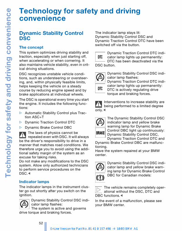
Te
ch
no
log
y fo
r sa
fety
an
d d
rivi
ng
co
nve
nie
nc
e
52
Technology for safety and driving convenience
Dynamic Stability Control DSC
The conceptThis system optimizes driving stability and traction, especially when just starting off, when accelerating or when cornering. It also maintains vehicle stability, even in crit-ical driving situations.
DSC recognizes unstable vehicle condi-tions, such as understeering or oversteer-ing, and, within physically feasible limits, helps keeping the vehicle on a steady course by reducing engine speed and by brake applications at individual wheels.
The DSC is operational every time you start the engine. It includes the following func-tions:
> Automatic Stability Control plus Trac-tion ASC+T
> Dynamic Traction Control DTC
> Dynamic Brake Control DBC
The laws of physics cannot be repealed even with DSC. It will always
be the driver's responsibility to drive in a manner that matches road conditions. We therefore urge you to avoid using the addi-tional safety margin of the system as an excuse for taking risks.Do not make any modifications to the DSC system. Allow only authorized technicians to perform service procedures on the DSC.<
Indicator lamps The indicator lamps in the instrument clus-ter go out shortly after you switch on the ignition.
Dynamic Stability Control DSC indi-cator lamp flashes:The system is active and governs
drive torque and braking forces.
The indicator lamp stays lit:Dynamic Stability Control DSC and Dynamic Traction Control DTC have been switched off via the button.
Dynamic Traction Control DTC indi-cator lamp lights up permanently:DTC has been deactivated via the
DSC button.
Dynamic Stability Control DSC indi-cator lamp flashes:Dynamic Traction Control DTC indi-cator lamp lights up permanently:DTC is actively regulating drive torque and braking forces.
Interventions to increase stability are being performed to a limited degree
only.<
The Dynamic Stability Control DSC indicator lamp and yellow brake warning lamp for Dynamic Brake Control DBC light up continuously:Dynamic Stability Control DSC, Dynamic Traction Control DTC and
Dynamic Brake Control DBC are malfunc-tioning.Have the system repaired at your BMW center.
Dynamic Stability Control DSC indi-cator lamp and yellow brake warn-ing lamp for Dynamic Brake Control DBC for Canadian models:
The vehicle remains completely oper-ational without the DSC, DTC and
DBC functions.<
In the event of a malfunction, please see your BMW center.
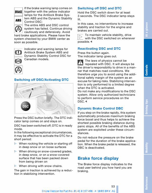
Refe
renc
eAt
a g
lanc
eCo
ntro
lsDr
ivin
g ti
psM
obili
ty
53
If the brake warning lamp comes on together with the yellow indicator lamps for the Antilock Brake Sys-tem ABS and the Dynamic Stability Control DSC:The entire ABS and DSC control system has failed. Continue driving cautiously and defensively. Avoid
hard brake applications. Please have the system checked by your BMW center as soon as possible.
Indicator and warning lamps for Antilock Brake System ABS and Dynamic Stability Control DSC for Canadian models.
Switching off DSC/Activating DTC
Press the DSC button briefly. The DTC indi-cator lamp comes on and stays on.
DSC has been switched off; DTC is in ready mode.In the following exceptional circumstances, it may be effective to activate the DTC for a short period:
> When rocking the vehicle or starting off in deep snow or on loose surfaces
> When driving on snow-covered grades, in deep snow, or on a snow-covered surface that has been packed down from being driven on
> When driving with snow chains.
The gain in traction is achieved by a reduc-tion in stabilizing intervention.
Switching off DSC and DTCHold the DSC switch down for at least 3 seconds. The DSC indicator lamp stays lit.
In this case, no interventions to increase stability and traction for the engine and brakes are carried out.
To maintain vehicle stability, drive with the DSC switched on whenever
possible.<
Reactivating DSC and DTCPress the button again.The indicator lamp goes out.
The laws of physics cannot be repealed with DSC. It will always be
the driver's responsibility to drive in a man-ner that matches road conditions. We therefore urge you to avoid using the addi-tional safety margin of the system as an excuse for taking risks. Stabilizing interven-tion is only performed to a limited degree when the DTC is activated.Do not make any modifications to the DSC system. Allow only authorized technicians to perform service procedures on the DSC.<
Dynamic Brake Control DBC If you step on the brake rapidly, this system automatically produces maximum braking force boost and thus helps to achieve the shortest possible braking distance during panic stops. All of the benefits of the ABS system are exploited under these circum-stances.
Do not reduce the pressure on the brake pedal for the duration of the brake applica-tion. When the brake pedal is released, the DBC is deactivated.
Brake force displayThe Brake force display indicates to the road user behind you how hard you are braking.
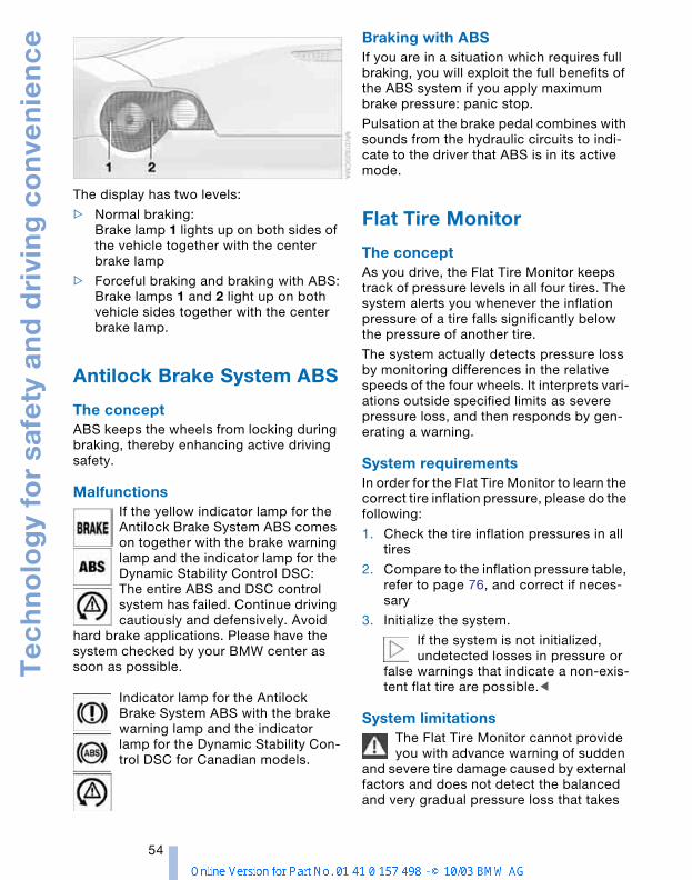
Te
ch
no
log
y fo
r sa
fety
an
d d
rivi
ng
co
nve
nie
nc
e
54
The display has two levels:
> Normal braking:Brake lamp 1 lights up on both sides of the vehicle together with the center brake lamp
> Forceful braking and braking with ABS:Brake lamps 1 and 2 light up on both vehicle sides together with the center brake lamp.
Antilock Brake System ABS
The conceptABS keeps the wheels from locking during braking, thereby enhancing active driving safety.
MalfunctionsIf the yellow indicator lamp for the Antilock Brake System ABS comes on together with the brake warning lamp and the indicator lamp for the Dynamic Stability Control DSC:The entire ABS and DSC control system has failed. Continue driving cautiously and defensively. Avoid
hard brake applications. Please have the system checked by your BMW center as soon as possible.
Indicator lamp for the Antilock Brake System ABS with the brake warning lamp and the indicator lamp for the Dynamic Stability Con-trol DSC for Canadian models.
Braking with ABSIf you are in a situation which requires full braking, you will exploit the full benefits of the ABS system if you apply maximum brake pressure: panic stop.
Pulsation at the brake pedal combines with sounds from the hydraulic circuits to indi-cate to the driver that ABS is in its active mode.
Flat Tire Monitor
The conceptAs you drive, the Flat Tire Monitor keeps track of pressure levels in all four tires. The system alerts you whenever the inflation pressure of a tire falls significantly below the pressure of another tire.
The system actually detects pressure loss by monitoring differences in the relative speeds of the four wheels. It interprets vari-ations outside specified limits as severe pressure loss, and then responds by gen-erating a warning.
System requirementsIn order for the Flat Tire Monitor to learn the correct tire inflation pressure, please do the following:
1. Check the tire inflation pressures in all tires
2. Compare to the inflation pressure table, refer to page 76, and correct if neces-sary
3. Initialize the system.
If the system is not initialized, undetected losses in pressure or
false warnings that indicate a non-exis-tent flat tire are possible.<
System limitationsThe Flat Tire Monitor cannot provide you with advance warning of sudden
and severe tire damage caused by external factors and does not detect the balanced and very gradual pressure loss that takes
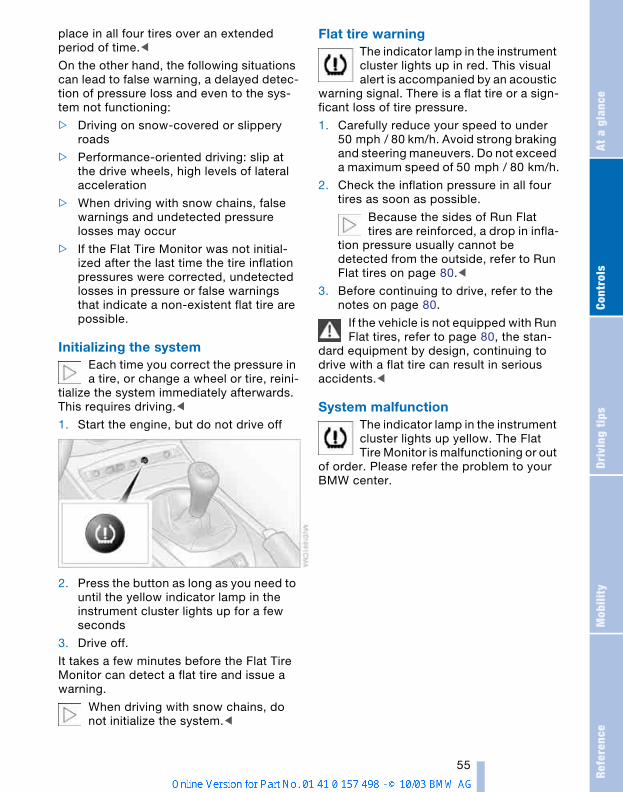
Refe
renc
eAt
a g
lanc
eCo
ntro
lsDr
ivin
g ti
psM
obili
ty
55
place in all four tires over an extended period of time.<
On the other hand, the following situations can lead to false warning, a delayed detec-tion of pressure loss and even to the sys-tem not functioning:
> Driving on snow-covered or slippery roads
> Performance-oriented driving: slip at the drive wheels, high levels of lateral acceleration
> When driving with snow chains, false warnings and undetected pressure losses may occur
> If the Flat Tire Monitor was not initial-ized after the last time the tire inflation pressures were corrected, undetected losses in pressure or false warnings that indicate a non-existent flat tire are possible.
Initializing the system Each time you correct the pressure in a tire, or change a wheel or tire, reini-
tialize the system immediately afterwards. This requires driving.<
1. Start the engine, but do not drive off
2. Press the button as long as you need to until the yellow indicator lamp in the instrument cluster lights up for a few seconds
3. Drive off.
It takes a few minutes before the Flat Tire Monitor can detect a flat tire and issue a warning.
When driving with snow chains, do not initialize the system.<
Flat tire warningThe indicator lamp in the instrument cluster lights up in red. This visual alert is accompanied by an acoustic
warning signal. There is a flat tire or a sign-ficant loss of tire pressure.
1. Carefully reduce your speed to under 50 mph / 80 km/h. Avoid strong braking and steering maneuvers. Do not exceed a maximum speed of 50 mph / 80 km/h.
2. Check the inflation pressure in all four tires as soon as possible.
Because the sides of Run Flat tires are reinforced, a drop in infla-
tion pressure usually cannot be detected from the outside, refer to Run Flat tires on page 80.<
3. Before continuing to drive, refer to the notes on page 80.
If the vehicle is not equipped with Run Flat tires, refer to page 80, the stan-
dard equipment by design, continuing to drive with a flat tire can result in serious accidents.<
System malfunctionThe indicator lamp in the instrument cluster lights up yellow. The Flat Tire Monitor is malfunctioning or out
of order. Please refer the problem to your BMW center.

Te
ch
no
log
y fo
r sa
fety
an
d d
rivi
ng
co
nve
nie
nc
e
56
Airbags
The following airbags are located under the marked covers:
1 Front airbags for driver and passenger
2 Side airbags for driver and passenger
3 Knee airbags for driver and passenger
Protective effectThe front airbags help protect the driver and passenger in the event of a head-on collision where the protection provided by the safety belt alone would not be ade-quate. The side airbags help provide pro-tection in the event of a collision from the side. Each of the side airbags is designed to help support the seat occupant's upper body. The knee airbags help provide addi-tional protection in the event of a head-on collision.
The airbags are deliberately not triggered in every impact situation, e.g. less severe accidents, certain roll-over conditions, or rear-end collisions.
For information on the correct seating posi-tion, refer to page 27.
Do not apply adhesive materials to the cover panels of the airbags, cover
them or modify them in any other way. Do not attempt to remove the airbag retention system from the vehicle. Never modify or tamper with either the wiring or the individ-ual components in the airbag system. This category includes the upholstery in the center of the steering wheel, on the instru-ment panel, the side trim panels on the doors. Do not attempt to remove or dis-mantle the steering wheel. Do not touch the individual components
directly after the system has been trig-gered, because there is a danger of burns.If you note any indication of system mal-function, if you desire to have an airbag deactivated, or if the airbag retention sys-tem is triggered in response to an accident, you should always entrust all inspection, repair and dismantling operations to your BMW center. Unprofessional attempts to service the sys-tem could lead to failure in an emergency or undesired airbag activation, either of which could result in personal injury. To ensure compliance with official safety regulations, please also entrust disposal of airbag generators to a BMW center.<
Airbag warning information is also provided on the sun visors.
Automatic deactivation of the passenger airbags
Before transporting a child on the passenger seat be sure to observe
the information/instructions under Trans-porting children safely, refer to page 33.<
Your BMW has a seat occupation detection system. By evaluating the weight on the passenger's seat, the system detects whether or not the seat is occupied by a child in the child-restraint system or an adult.
> When a child is seated in the child-restraint system, the front, side and knee airbags are automatically deacti-vated on the passenger's side.
> When an adult is traveling in the front seat or it is unoccupied, the front, side and knee airbags remain active on the passenger's side.
Although not desired, it can occur in the case of heavier children that the
passenger airbags remain active or, in the case of very light adults or young persons, that the passenger airbags are deactivated. The condition of the passenger airbag sys-tem is shown by the indicator lamp in the central console, refer to Indicator lamps below. If the indicator lamp signals that the passenger airbags are active and you wish
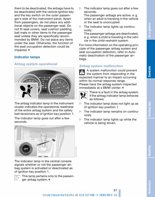
Refe
renc
eAt
a g
lanc
eCo
ntro
lsDr
ivin
g ti
psM
obili
ty
57
them to be deactivated, the airbags have to be deactivated with the vehicle ignition key and the key switch on the outer passen-ger's side of the instrument panel. Apart from passengers, do not place any addi-tional objects on the passenger seat. Do not fit seat covers, seat cushion padding, ball mats or other items to the passenger seat unless they are specifically recom-mended by BMW. Do not place any items under the seat. Otherwise, the function of the seat occupation detection could be impaired.<
Indicator lamps
Airbag system operational
The airbag indicator lamp in the instrument cluster indicates the operational readiness of the entire airbag system and the safety belt tensioners as of ignition key position 1.
The indicator lamp goes out after a few seconds.
The indicator lamp in the central console signals whether or not the passenger air-bag system is activated or deactivated as of ignition key position 1.
This lamp pertains only to the passen-ger airbag system.<
> The indicator lamp goes out after a few seconds:The passenger airbags are active, e.g. when an adult is traveling in the vehicle or the seat is unoccupied
> The indicator lamp lights up continu-ously: The passenger airbags are deactivated, e.g. when a child is traveling in the vehi-cle in the child-restraint system.
For more information on the operating prin-ciple of the passenger airbag system and seat occupation detection, refer to Auto-matic deactivation of the passenger air-bags.
Airbag system malfunctionA system malfunction could prevent the system from responding in the
expected manner to an impact occurring within its normal response range.Please have the airbag system inspected immediately at a BMW center.<
There is a fault in the airbag system if the airbag indicator lamp behaves as follows:
> The indicator lamp does not light up as of ignition key position 1
> The indicator lamp remains on continu-ously
> The indicator lamp lights up while the vehicle is being driven.
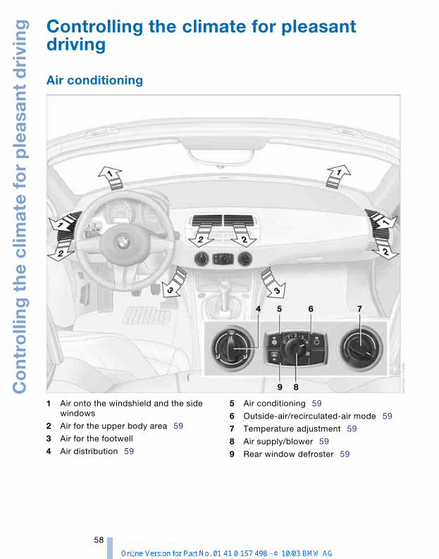
Co
ntr
olli
ng
th
e c
limat
e f
or
ple
asan
t d
rivi
ng
58
Controlling the climate for pleasant driving
Air conditioning
1 Air onto the windshield and the side windows
2 Air for the upper body area 59
3 Air for the footwell
4 Air distribution 59
5 Air conditioning 59
6 Outside-air/recirculated-air mode 59
7 Temperature adjustment 59
8 Air supply/blower 59
9 Rear window defroster 59
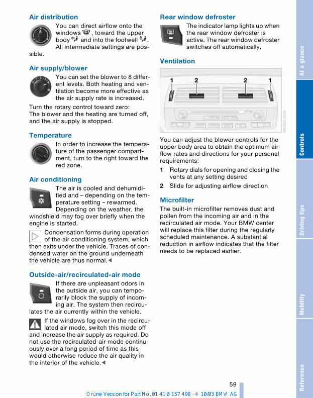
Refe
renc
eAt
a g
lanc
eCo
ntro
lsDr
ivin
g ti
psM
obili
ty
59
Air distribution You can direct airflow onto the windows , toward the upper body and into the footwell . All intermediate settings are pos-
sible.
Air supply/blower You can set the blower to 8 differ-ent levels. Both heating and ven-tilation become more effective as the air supply rate is increased.
Turn the rotary control toward zero: The blower and the heating are turned off, and the air supply is stopped.
Temperature In order to increase the tempera-ture of the passenger compart-ment, turn to the right toward the red zone.
Air conditioning The air is cooled and dehumidi-fied and – depending on the tem-perature setting – rewarmed.Depending on the weather, the
windshield may fog over briefly when the engine is started.
Condensation forms during operation of the air conditioning system, which
then exits under the vehicle. Traces of con-densed water on the ground underneath the vehicle are thus normal.<
Outside-air/recirculated-air mode If there are unpleasant odors in the outside air, you can tempo-rarily block the supply of incom-ing air. The system then recircu-
lates the air currently within the vehicle.
If the windows fog over in the recircu-lated air mode, switch this mode off
and increase the air supply as required. Do not use the recirculated-air mode continu-ously over a long period of time as this would otherwise reduce the air quality in the interior of the vehicle.<
Rear window defroster The indicator lamp lights up when the rear window defroster is active. The rear window defroster switches off automatically.
Ventilation
You can adjust the blower controls for the upper body area to obtain the optimum air-flow rates and directions for your personal requirements:
1 Rotary dials for opening and closing the vents at any setting desired
2 Slide for adjusting airflow direction
MicrofilterThe built-in microfilter removes dust and pollen from the incoming air and in the recirculated air mode. Your BMW center will replace this filter during the regularly scheduled maintenance. A substantial reduction in airflow indicates that the filter needs to be replaced earlier.
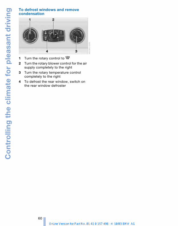
Co
ntr
olli
ng
th
e c
limat
e f
or
ple
asan
t d
rivi
ng
60
To defrost windows and remove condensation
1 Turn the rotary control to
2 Turn the rotary blower control for the air supply completely to the right
3 Turn the rotary temperature control completely to the right
4 To defrost the rear window, switch on the rear window defroster

Refe
renc
eAt
a g
lanc
eCo
ntro
lsDr
ivin
g ti
psM
obili
ty
61
Automatic climate control*
1 Air onto the windshield and the side windows
2 Air for the upper body area 63
3 Air for the footwell
4 Individual air distribution 62
5 To defrost windows and remove condensation 62
6 Automatic air distribution and air supply 62
7 Air supply/blower 62
8 Air conditioning 59
9 Maximum cooling 62
10 Temperature 62
11 Outside air/Automatic recirculated air control AUC/recirculated air mode 63
12 Rear window defroster 63
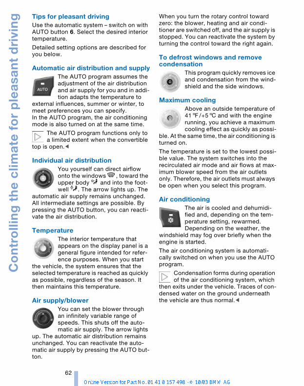
Co
ntr
olli
ng
th
e c
limat
e f
or
ple
asan
t d
rivi
ng
62
Tips for pleasant drivingUse the automatic system – switch on with AUTO button 6. Select the desired interior temperature.
Detailed setting options are described for you below.
Automatic air distribution and supplyThe AUTO program assumes the adjustment of the air distribution and air supply for you and in addi-tion adapts the temperature to
external influences, summer or winter, to meet preferences you can specify. In the AUTO program, the air conditioning mode is also turned on at the same time.
The AUTO program functions only to a limited extent when the convertible
top is open.<
Individual air distribution You yourself can direct airflow onto the windows , toward the upper body and into the foot-well . The arrow lights up. The
automatic air supply remains unchanged. All intermediate settings are possible. By pressing the AUTO button, you can reacti-vate the air distribution.
Temperature The interior temperature that appears on the display panel is a general figure intended for refer-ence purposes. When you start
the vehicle, the system ensures that the selected temperature is reached as quickly as possible, regardless of the season. It then maintains this temperature.
Air supply/blower You can set the blower through an infinitely variable range of speeds. This shuts off the auto-matic air supply. The arrow lights
up. The automatic air distribution remains unchanged. You can reactivate the auto-matic air supply by pressing the AUTO but-ton.
When you turn the rotary control toward zero: the blower, heating and air condi-tioner are switched off, and the air supply is stopped. You can reactivate the system by turning the control toward the right again.
To defrost windows and remove condensation
This program quickly removes ice and condensation from the wind-shield and the side windows.
Maximum cooling Above an outside temperature of 417/+56 and with the engine running, you achieve a maximum cooling effect as quickly as possi-
ble. At the same time, the air conditioning is turned on.
The temperature is set to the lowest possi-ble value. The system switches into the recirculated air mode and air flows at max-imum blower speed from the air outlets only. Therefore, the air outlets must always be open when you select this program.
Air conditioningThe air is cooled and dehumidi-fied and, depending on the tem-perature setting, rewarmed.Depending on the weather, the
windshield may fog over briefly when the engine is started.
The air conditioning system is automati-cally switched on when you use the AUTO program.
Condensation forms during operation of the air conditioning system, which
then exits under the vehicle. Traces of con-densed water on the ground underneath the vehicle are thus normal.<
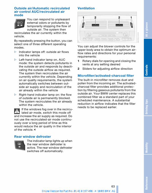
Refe
renc
eAt
a g
lanc
eCo
ntro
lsDr
ivin
g ti
psM
obili
ty
63
Outside air/Automatic recirculated air control AUC/recirculated air mode
You can respond to unpleasant external odors or pollutants by temporarily stopping the flow of outside air. The system then
recirculates the air currently within the vehicle.
By repeatedly pressing the button, you can select one of three different operating modes.
> Indicator lamps off: outside air flows into the vehicle
> Left-hand indicator lamp on, AUC mode: the system detects pollutants in the outside air and responds by deacti-vating the outside airflow as required. The system then recirculates the air currently within the vehicle. Depending on air quality requirements, the system automatically switches between out-side air supply and recirculation of the air already within the vehicle
> Right-hand indicator lamp on: the flow of outside air is permanently blocked. The system recirculates the air already within the vehicle.
If the windows fog over in the recircu-lated air mode, switch this mode off
and increase the air supply as required. Do not use the recirculated-air mode continu-ously over a long period of time as this would reduce the air quality in the interior of the vehicle.<
Rear window defroster The indicator lamp lights up when the rear window defroster is active. The rear window defroster switches off automatically.
Ventilation
You can adjust the blower controls for the upper body area to obtain the optimum air-flow rates and directions for your personal requirements:
1 Rotary dials for opening and closing the vents at any setting desired
2 Sliders for adjusting airflow direction
Microfilter/activated-charcoal filterThe built-in microfilter removes dust and pollen from the incoming air. The activated-charcoal filter provides additional protec-tion by filtering gaseous pollutants from the outside air. Your BMW center replaces this combined filter as a standard part of your scheduled maintenance. A substantial reduction in airflow indicates that the filter needs to be replaced earlier.

Inte
rio
r c
on
ven
ien
ce
s
64
Interior conveniences
Glove compartment
To open
Press the two push buttons together.
To closeSwing the door up.
To prevent injury in the event of an accident, close the glove compart-
ment immediately after use.<
Storage compartments
Storage compartment between backrests
To open1. Press button; see arrow 1
2. Swing the cover downward.
To closeSwing the door up.
Locking/unlockingThe storage compartment between the backrests is automatically locked and unlocked with the central locking system.
Releasing manually In the event of an electrical malfunction of the central locking system, you can manu-ally unlock the storage compartment between the seats.
1. Pull on the cord in the rear luggage compartment panel.The storage compartment between the seats unlocks
2. Press button; see arrow 1.
Other compartments and nets* You will find additional storage compart-ments in the front doors and in the center console.
Depending on the particular version, the vehicle may also be equipped with two storage compartments behind the seats.
A net* is located on the passenger side along the center console.
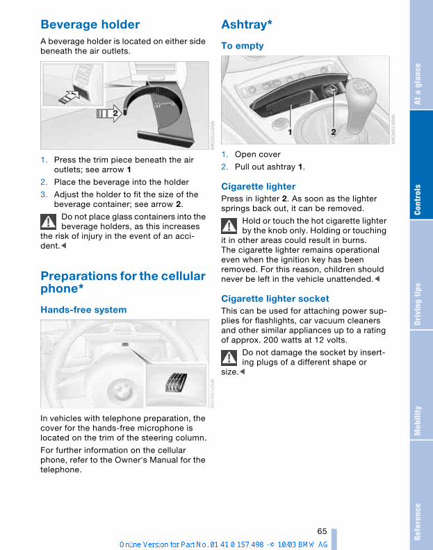
Refe
renc
eAt
a g
lanc
eCo
ntro
lsDr
ivin
g ti
psM
obili
ty
65
Beverage holder A beverage holder is located on either side beneath the air outlets.
1. Press the trim piece beneath the air outlets; see arrow 1
2. Place the beverage into the holder
3. Adjust the holder to fit the size of the beverage container; see arrow 2.
Do not place glass containers into the beverage holders, as this increases
the risk of injury in the event of an acci-dent.<
Preparations for the cellular phone*
Hands-free system
In vehicles with telephone preparation, the cover for the hands-free microphone is located on the trim of the steering column.
For further information on the cellular phone, refer to the Owner's Manual for the telephone.
Ashtray*
To empty
1. Open cover
2. Pull out ashtray 1.
Cigarette lighterPress in lighter 2. As soon as the lighter springs back out, it can be removed.
Hold or touch the hot cigarette lighter by the knob only. Holding or touching
it in other areas could result in burns.The cigarette lighter remains operational even when the ignition key has been removed. For this reason, children should never be left in the vehicle unattended.<
Cigarette lighter socketThis can be used for attaching power sup-plies for flashlights, car vacuum cleaners and other similar appliances up to a rating of approx. 200 watts at 12 volts.
Do not damage the socket by insert-ing plugs of a different shape or
size.<
Driving tipsDriving tips provides you with informationyou will need in certain driving situations
and when using special operating modes.
Sp
ec
ial o
pe
rati
ng
inst
ruc
tio
ns
68
Special operating instructions
Break-in procedures To ensure that your vehicle provides maxi-mum economy throughout a long service life, we request that you observe the fol-lowing:
Engine and differentialUp to 1,200 miles / 2,000 km:Drive at varying engine and road speeds, but do not exceed the following engine or road speed:
4,500 rpm / 4,500/min or 100 mph / 160 km/h.
Obey your local and state maximum speed limits.
Refrain from using full throttle and avoid pressing the accelerator beyond the kick-down point.
After you have driven 1,200 miles / 2,000 km, you can gradually increase the engine or road speeds.
You should also comply with these break-in procedures if the engine or differential is replaced later in the course of the vehicle's service life.
Sequential manual gearbox SMGUp to 1,200 miles / 2,000 km: Avoid using the acceleration assistant dur-ing the vehicle's break-in period.
TiresDue to technical factors associated with their manufacture, tires do not achieve their full traction potential until an initial break-in period has elapsed. You should therefore drive with extra caution during the first 200 miles / 300 km.
Obey your local and state maximum speed limits.
When the vehicle is operated on wet or slushy roads, a wedge of water
may form between the tire and the road
surface. This phenomenon is referred to as hydroplaning and can lead to partial or complete loss of traction, vehicle control and braking effectiveness. Reduce your speed on wet roads.<
Brake systemApprox. 300 miles / 500 km must elapse before the brake pads and rotors achieve their optimal surface and wear pattern.
To break in the separate parking brake drums, apply the parking brake lightly when coasting to a standstill – at a traffic signal, for instance; use caution to avoid posing a danger to other road users.
To avoid corrosion, repeat this procedure from time to time.
The brake lamps do not come on when the parking brake is set.
Vacuum for the brake system servo unit on your BMW is available only
when the engine is running. When you move the car with the engine off, e.g. by towing, substantially higher levels of pedal force will be required to brake the vehicle.<
ClutchThe clutch will achieve its optimal function-ality after approx. 300 miles / 500 km. Shift gears carefully during the break-in period.
Refe
renc
eAt
a g
lanc
eCo
ntro
lsDr
ivin
g ti
psM
obili
ty
69
Driving notes
Parking the vehicleCondensation forms in the air conditioner system during operation, which then exits under the vehicle. Traces of condensed water on the ground underneath the vehi-cle are thus normal.
BrakesDo not drive with your foot resting on the brake pedal. Even light but con-
sistent pedal pressure can lead to high temperatures, brake wear and possibly even brake failure.
Hydroplaning When driving on wet or slushy roads, reduce vehicle speed. If you do not, a
wedge of water may form between the tires and the road surface. This phenomenon can lead to partial or complete loss of trac-tion, vehicle control and braking effective-ness.<
Driving through waterDo not drive through water on the road if it is deeper than 1 ft / 30 cm,
and then only at walking speed. Otherwise, the vehicle's engine, the electrical systems and the transmission may be damaged.<
High temperaturesHigh temperatures occur with every vehicle equipped with a catalytic con-
verter. Heat shields are installed adjacent to some sections of the exhaust system. Never remove these shields; do not apply undercoating to their surfaces. When driv-ing, standing at idle and parking the vehi-cle, take care to avoid contact between the hot exhaust system and flammable materi-als, e.g. hay, leaves, grass, etc. Such con-tact could lead to a fire, resulting in serious personal injury and property damage.<
Brake system
Indicator lampThe indicator lamp lights up although the parking brake is not engaged:
Check the brake fluid level. It is very impor-tant that you follow the instructions on page 85 before driving on.
Disc brakes
CorrosionLimited vehicle use, extended periods with the vehicle parked or in storage, and oper-ating conditions in which braking is restricted to gentle, low-pressure applica-tions will all increase the tendency for cor-rosion to form on the rotors and contamina-tion to accumulate on the brake pads. This occurs because the minimal pressure which must be exerted by the pads to clean the rotors by brake applications is not reached.
If the brake rotors are corroded, they will tend to respond to braking with a pulsating effect which even extended application will fail to cure.
Wet roadsWhen driving in heavy rain and on wet roads, it is useful to apply light pressure to the brake pedal every few miles. Watch traffic conditions to ensure that this maneu-ver does not endanger other road users. The resulting heat dries the brake rotors and brake pads. Immediate braking control is then available if necessary.
InclinesExtended or steep mountain descents should be driven in the gear or drive posi-tion in which only minimal periodic brake application is required. This helps avoid placing excessive loads on the brake sys-tem. Observe the maximum allowable engine speed when doing so; refer to page 48.
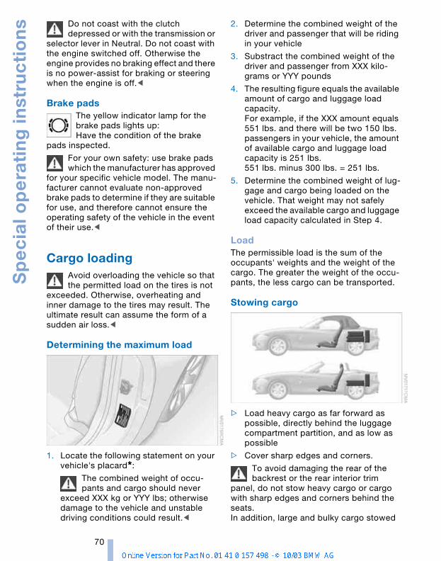
Sp
ec
ial o
pe
rati
ng
inst
ruc
tio
ns
70
Do not coast with the clutch depressed or with the transmission or
selector lever in Neutral. Do not coast with the engine switched off. Otherwise the engine provides no braking effect and there is no power-assist for braking or steering when the engine is off.<
Brake pads The yellow indicator lamp for the brake pads lights up:Have the condition of the brake
pads inspected.
For your own safety: use brake pads which the manufacturer has approved
for your specific vehicle model. The manu-facturer cannot evaluate non-approved brake pads to determine if they are suitable for use, and therefore cannot ensure the operating safety of the vehicle in the event of their use.<
Cargo loading Avoid overloading the vehicle so that the permitted load on the tires is not
exceeded. Otherwise, overheating and inner damage to the tires may result. The ultimate result can assume the form of a sudden air loss.<
Determining the maximum load
1. Locate the following statement on your vehicle's placard*:
The combined weight of occu-pants and cargo should never
exceed XXX kg or YYY lbs; otherwise damage to the vehicle and unstable driving conditions could result.<
2. Determine the combined weight of the driver and passenger that will be riding in your vehicle
3. Substract the combined weight of the driver and passenger from XXX kilo-grams or YYY pounds
4. The resulting figure equals the available amount of cargo and luggage load capacity.For example, if the XXX amount equals 551 lbs. and there will be two 150 lbs. passengers in your vehicle, the amount of available cargo and luggage load capacity is 251 lbs.551 lbs. minus 300 lbs. = 251 lbs.
5. Determine the combined weight of lug-gage and cargo being loaded on the vehicle. That weight may not safely exceed the available cargo and luggage load capacity calculated in Step 4.
LoadThe permissible load is the sum of the occupants' weights and the weight of the cargo. The greater the weight of the occu-pants, the less cargo can be transported.
Stowing cargo
> Load heavy cargo as far forward as possible, directly behind the luggage compartment partition, and as low as possible
> Cover sharp edges and corners.
To avoid damaging the rear of the backrest or the rear interior trim
panel, do not stow heavy cargo or cargo with sharp edges and corners behind the seats.In addition, large and bulky cargo stowed
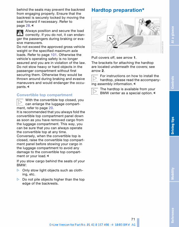
Refe
renc
eAt
a g
lanc
eCo
ntro
lsDr
ivin
g ti
psM
obili
ty
71
behind the seats may prevent the backrest from engaging properly. Ensure that the backrest is securely locked by moving the seat forward if necessary. Refer to page 28.<
Always position and secure the load correctly. If you do not, it can endan-
ger the passengers during braking or eva-sive maneuvers.Do not exceed the approved gross vehicle weight or the specified maximum axle loads. Refer to page 101. Otherwise the vehicle's operating safety is no longer assured and you are in violation of the law.Do not stow heavy or hard objects in the passenger compartment without first securing them. Otherwise they would be thrown around during braking and evasive maneuvers and would endanger the occu-pants.<
Convertible top compartmentWith the convertible top closed, you can enlarge the luggage compart-
ment, refer to page 20.It is recommended that you always fold the convertible top compartment panel down as soon as you have removed cargo from the luggage compartment. This way, you can be sure that you can always operate the convertible top at any time.Conversely, when the convertible top is closed, raise the convertible top compart-ment panel before stowing your cargo in the luggage compartment to avoid any damage to the convertible top compart-ment or your load.<
If you stow cargo behind the seats of your BMW:
> Only stow light objects such as cloth-ing, etc.
> Do not pile objects higher than the top edge of the backrests.
Hardtop preparation*
Pull covers off, see arrow 1.
The brackets for attaching the hardtop are located underneath the covers; see arrow 2.
For instructions on how to install the hardtop, please read the accompany-
ing assembly information.<
The hardtop is available from your BMW center as a special option.<
MobilityTo ensure that you stay mobile,
the following chapter provides you withimportant information on fuels and fluids,
tires and wheels, maintenance proceduresand steps to take in the event of a break-
down.
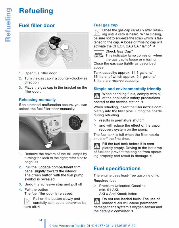
Re
fue
ling
74
Refueling
Fuel filler door
1. Open fuel filler door
2. Turn the gas cap in a counter-clockwise direction
3. Place the gas cap in the bracket on the filler door.
Releasing manuallyIf an electrical malfunction occurs, you can unlock the fuel filler door manually:
1. Remove the covers of the tail lamps by turning the lock to the right; refer also to page 90
2. Pull the luggage compartment trim panel slightly toward the interior.The green button with the fuel pump symbol is revealed
3. Undo the adhesive strip and pull off
4. Pull the buttonThe fuel filler door is released.
Pull on the button slowly and carefully as it could otherwise be
torn off.<
Fuel gas capClose the gas cap carefully after refuel-ing until a click is heard. While closing,
be sure not to squeeze the strap which is fas-tened to the cap. A loose or missing cap will activate the CHECK GAS CAP lamp*.<
Check Gas Cap*This indicator lamp comes on when the gas cap is loose or missing.
Close the gas cap tightly as described above.
Tank capacity: approx. 14.5 gallons/55 liters, of which approx. 2.1 gallons/8 liters are reserve capacity.
Simple and environmentally friendlyWhen handling fuels, comply with all of the applicable safety precautions
posted at the service station.<
When refueling, insert the filler nozzle com-pletely into the filler pipe. Lifting the nozzle during refueling
> results in premature shutoff
> and will reduce the effect of the vapor recovery system on the pump.
The fuel tank is full when the filler nozzle shuts off the first time.
Fill the fuel tank before it is com-pletely empty. Driving to the last drop
of fuel can prevent the engine from operat-ing properly and result in damage.<
Fuel specificationsThe engine uses lead-free gasoline only.
Required fuel:
> Premium Unleaded Gasoline, min. 91 AKI. AKI = Anti Knock Index
Do not use leaded fuels. The use of leaded fuels will cause permanent
damage to the system's oxygen sensor and the catalytic converter.<
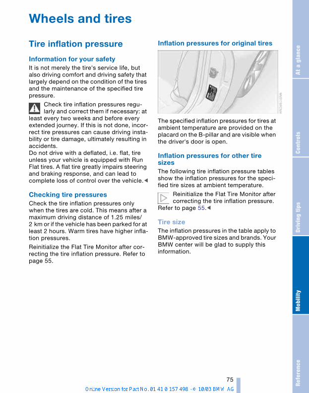
Refe
renc
eAt
a g
lanc
eCo
ntro
lsDr
ivin
g ti
psM
obili
ty
75
Wheels and tires
Tire inflation pressure
Information for your safetyIt is not merely the tire's service life, but also driving comfort and driving safety that largely depend on the condition of the tires and the maintenance of the specified tire pressure.
Check tire inflation pressures regu-larly and correct them if necessary: at
least every two weeks and before every extended journey. If this is not done, incor-rect tire pressures can cause driving insta-bility or tire damage, ultimately resulting in accidents.Do not drive with a deflated, i.e. flat, tire unless your vehicle is equipped with Run Flat tires. A flat tire greatly impairs steering and braking response, and can lead to complete loss of control over the vehicle.<
Checking tire pressuresCheck the tire inflation pressures only when the tires are cold. This means after a maximum driving distance of 1.25 miles/2 km or if the vehicle has been parked for at least 2 hours. Warm tires have higher infla-tion pressures.
Reinitialize the Flat Tire Monitor after cor-recting the tire inflation pressure. Refer to page 55.
Inflation pressures for original tires
The specified inflation pressures for tires at ambient temperature are provided on the placard on the B-pillar and are visible when the driver's door is open.
Inflation pressures for other tire sizesThe following tire inflation pressure tables show the inflation pressures for the speci-fied tire sizes at ambient temperature.
Reinitialize the Flat Tire Monitor after correcting the tire inflation pressure.
Refer to page 55.<
Tire sizeThe inflation pressures in the table apply to BMW-approved tire sizes and brands. Your BMW center will be glad to supply this information.
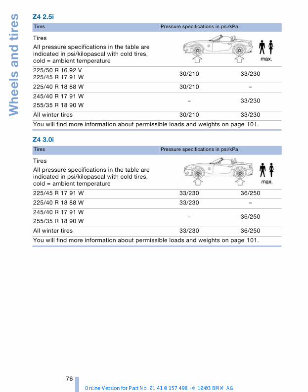
Wh
ee
ls a
nd
tir
es
76
Z4 2.5i
Z4 3.0i
Tires Pressure specifications in psi/kPa
Tires
All pressure specifications in the table are indicated in psi/kilopascal with cold tires, cold = ambient temperature
225/50 R 16 92 V225/45 R 17 91 W
30/210 33/230
225/40 R 18 88 W 30/210 –
245/40 R 17 91 W
255/35 R 18 90 W– 33/230
All winter tires 30/210 33/230
You will find more information about permissible loads and weights on page 101.
Tires Pressure specifications in psi/kPa
Tires
All pressure specifications in the table are indicated in psi/kilopascal with cold tires, cold = ambient temperature
225/45 R 17 91 W 33/230 36/250
225/40 R 18 88 W 33/230 –
245/40 R 17 91 W
255/35 R 18 90 W– 36/250
All winter tires 33/230 36/250
You will find more information about permissible loads and weights on page 101.
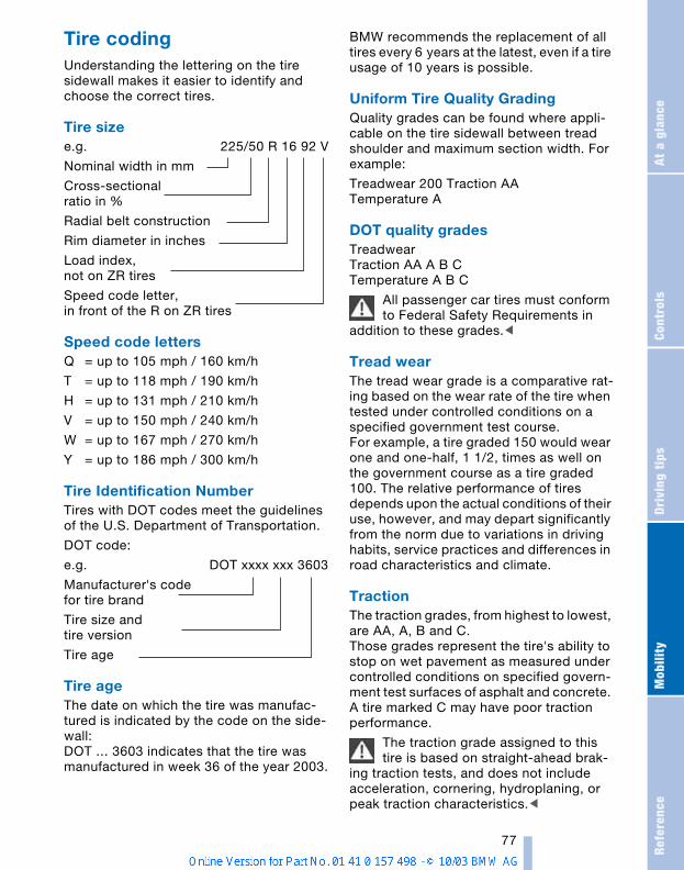
Refe
renc
eAt
a g
lanc
eCo
ntro
lsDr
ivin
g ti
psM
obili
ty
77
Tire codingUnderstanding the lettering on the tire sidewall makes it easier to identify and choose the correct tires.
Tire size e.g. 225/50 R 16 92 V
Nominal width in mm
Cross-sectionalratio in %
Radial belt construction
Rim diameter in inches
Load index, not on ZR tires
Speed code letter, in front of the R on ZR tires
Speed code lettersQ = up to 105 mph / 160 km/h
T = up to 118 mph / 190 km/h
H = up to 131 mph / 210 km/h
V = up to 150 mph / 240 km/h
W = up to 167 mph / 270 km/h
Y = up to 186 mph / 300 km/h
Tire Identification NumberTires with DOT codes meet the guidelines of the U.S. Department of Transportation.
DOT code:
e.g. DOT xxxx xxx 3603
Manufacturer's code for tire brand
Tire size and tire version
Tire age
Tire ageThe date on which the tire was manufac-tured is indicated by the code on the side-wall:DOT … 3603 indicates that the tire was manufactured in week 36 of the year 2003.
BMW recommends the replacement of all tires every 6 years at the latest, even if a tire usage of 10 years is possible.
Uniform Tire Quality GradingQuality grades can be found where appli-cable on the tire sidewall between tread shoulder and maximum section width. For example:
Treadwear 200 Traction AA Temperature A
DOT quality gradesTreadwear Traction AA A B C Temperature A B C
All passenger car tires must conform to Federal Safety Requirements in
addition to these grades.<
Tread wearThe tread wear grade is a comparative rat-ing based on the wear rate of the tire when tested under controlled conditions on a specified government test course. For example, a tire graded 150 would wear one and one-half, 1 1/2, times as well on the government course as a tire graded 100. The relative performance of tires depends upon the actual conditions of their use, however, and may depart significantly from the norm due to variations in driving habits, service practices and differences in road characteristics and climate.
TractionThe traction grades, from highest to lowest, are AA, A, B and C. Those grades represent the tire's ability to stop on wet pavement as measured under controlled conditions on specified govern-ment test surfaces of asphalt and concrete. A tire marked C may have poor traction performance.
The traction grade assigned to this tire is based on straight-ahead brak-
ing traction tests, and does not include acceleration, cornering, hydroplaning, or peak traction characteristics.<
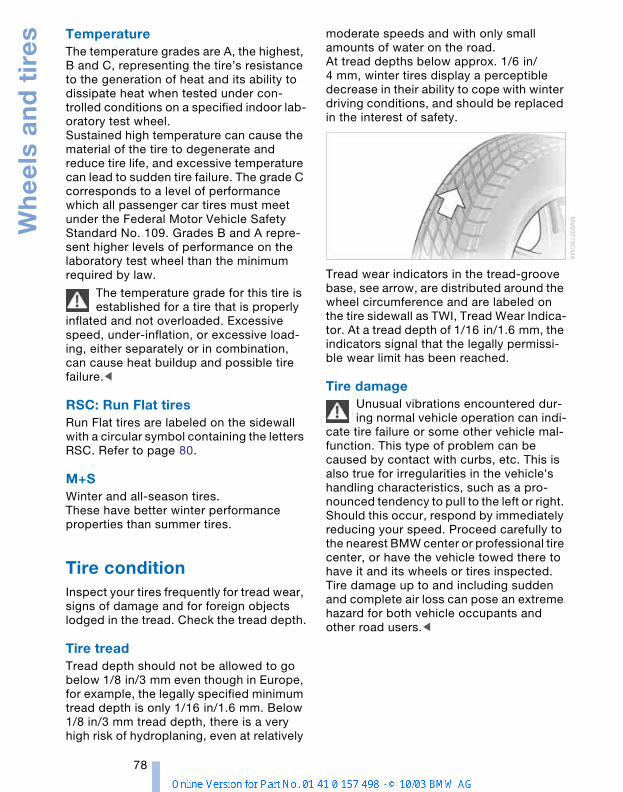
Wh
ee
ls a
nd
tir
es
78
TemperatureThe temperature grades are A, the highest, B and C, representing the tire’s resistance to the generation of heat and its ability to dissipate heat when tested under con-trolled conditions on a specified indoor lab-oratory test wheel. Sustained high temperature can cause the material of the tire to degenerate and reduce tire life, and excessive temperature can lead to sudden tire failure. The grade C corresponds to a level of performance which all passenger car tires must meet under the Federal Motor Vehicle Safety Standard No. 109. Grades B and A repre-sent higher levels of performance on the laboratory test wheel than the minimum required by law.
The temperature grade for this tire is established for a tire that is properly
inflated and not overloaded. Excessive speed, under-inflation, or excessive load-ing, either separately or in combination, can cause heat buildup and possible tire failure.<
RSC: Run Flat tiresRun Flat tires are labeled on the sidewall with a circular symbol containing the letters RSC. Refer to page 80.
M+SWinter and all-season tires.These have better winter performance properties than summer tires.
Tire condition Inspect your tires frequently for tread wear, signs of damage and for foreign objects lodged in the tread. Check the tread depth.
Tire tread Tread depth should not be allowed to go below 1/8 in/3 mm even though in Europe, for example, the legally specified minimum tread depth is only 1/16 in/1.6 mm. Below 1/8 in/3 mm tread depth, there is a very high risk of hydroplaning, even at relatively
moderate speeds and with only small amounts of water on the road.At tread depths below approx. 1/6 in/4 mm, winter tires display a perceptible decrease in their ability to cope with winter driving conditions, and should be replaced in the interest of safety.
Tread wear indicators in the tread-groove base, see arrow, are distributed around the wheel circumference and are labeled on the tire sidewall as TWI, Tread Wear Indica-tor. At a tread depth of 1/16 in/1.6 mm, the indicators signal that the legally permissi-ble wear limit has been reached.
Tire damage Unusual vibrations encountered dur-ing normal vehicle operation can indi-
cate tire failure or some other vehicle mal-function. This type of problem can be caused by contact with curbs, etc. This is also true for irregularities in the vehicle's handling characteristics, such as a pro-nounced tendency to pull to the left or right. Should this occur, respond by immediately reducing your speed. Proceed carefully to the nearest BMW center or professional tire center, or have the vehicle towed there to have it and its wheels or tires inspected. Tire damage up to and including sudden and complete air loss can pose an extreme hazard for both vehicle occupants and other road users.<
Refe
renc
eAt
a g
lanc
eCo
ntro
lsDr
ivin
g ti
psM
obili
ty
79
Wheel and tire replacement Unprofessional attempts by laymen to service tires can lead to damage and
accidents. Have this work performed by skilled pro-fessionals only. Any BMW center has the required technical knowledge and the proper equipment and will be happy to assist you.<
The correct wheel and tire combination also affects various systems that would otherwise be impaired, for example ABS or DSC.
Have the wheels balanced after each tire or wheel replacement.
BMW advises against using retreaded tires, since driving safety may be
impaired. This is due to possible variations in casing structures and, in some cases, to their extreme age, factors which can lead to a decrease in their durability.<
The correct wheels and tiresBMW recommends using only wheels and tires that have been tested and
approved by BMW for your particular vehi-cle model, as otherwise body contact and serious accidents can result despite the use of the same nominal size, e.g. due to manufacturing tolerances. If non-approved wheels and tires are used, BMW cannot evaluate their suitability, and therefore can-not be held liable for driving safety.<
To maintain good handling and vehicle response, use only tires of a single brand and tread configuration. In the event of a flat tire, remount the previous wheel and tire combination as soon as possible.
Recommended tire sizes and brandsBMW tests certain tire brands for each tire size, classifies them as road-safe and approves them. You can best find out about these at a specialized shop, particu-larly your BMW center. Observe any coun-try-specific regulations, e.g. on making a corresponding entry in the vehicle docu-ments.
The factory-approved radial-ply tires are matched to your vehicle and have been selected to provide optimum safety and driving comfort when used properly.
Run Flat tires fitted Use only Run Flat tires, since no spare wheel is available in the event of a flat.
Special characteristics of winter tiresBMW recommends the use of winter tires for operation under winter road conditions. While all-season tires, with M+S designa-tion, provide better winter traction than summer tires, they generally do not achieve the full performance of winter tires.
For mounting winter tires, refer to the descriptions under Tire condition and Wheel and tire replacement, pages 78, 79.
Run Flat tires fittedUse only winter Run Flat tires, since no spare wheel is available in the event of a flat.
Observing speed ratings Never exceed the maximum speed for which the winter tires are rated.
Unprofessional attempts by laymen to ser-vice tires can lead to damage and acci-dents. Have this work performed by skilled professionals only. The technicans at your BMW center will be glad to assist you with the required professional knowledge and specialized equipment.<
StorageStore tires in a cool, dry place, protecting them against light whenever possible. Pro-tect the tires from contact with oil, grease and fuel. Do not exceed the maximum tire inflation pressures specified on the tire sidewall.
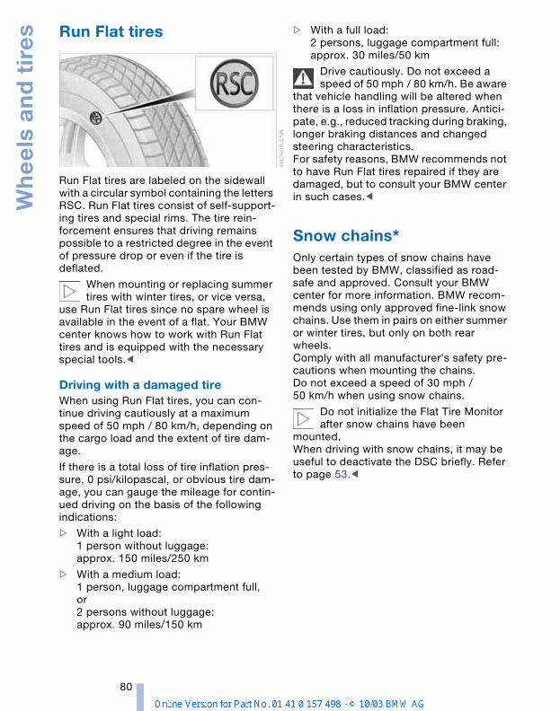
Wh
ee
ls a
nd
tir
es
80
Run Flat tires
Run Flat tires are labeled on the sidewall with a circular symbol containing the letters RSC. Run Flat tires consist of self-support-ing tires and special rims. The tire rein-forcement ensures that driving remains possible to a restricted degree in the event of pressure drop or even if the tire is deflated.
When mounting or replacing summer tires with winter tires, or vice versa,
use Run Flat tires since no spare wheel is available in the event of a flat. Your BMW center knows how to work with Run Flat tires and is equipped with the necessary special tools.<
Driving with a damaged tireWhen using Run Flat tires, you can con-tinue driving cautiously at a maximum speed of 50 mph / 80 km/h, depending on the cargo load and the extent of tire dam-age.
If there is a total loss of tire inflation pres-sure, 0 psi/kilopascal, or obvious tire dam-age, you can gauge the mileage for contin-ued driving on the basis of the following indications:
> With a light load:1 person without luggage:approx. 150 miles/250 km
> With a medium load:1 person, luggage compartment full, or 2 persons without luggage: approx. 90 miles/150 km
> With a full load:2 persons, luggage compartment full:approx. 30 miles/50 km
Drive cautiously. Do not exceed a speed of 50 mph / 80 km/h. Be aware
that vehicle handling will be altered when there is a loss in inflation pressure. Antici-pate, e.g., reduced tracking during braking, longer braking distances and changed steering characteristics. For safety reasons, BMW recommends not to have Run Flat tires repaired if they are damaged, but to consult your BMW center in such cases.<
Snow chains* Only certain types of snow chains have been tested by BMW, classified as road-safe and approved. Consult your BMW center for more information. BMW recom-mends using only approved fine-link snow chains. Use them in pairs on either summer or winter tires, but only on both rear wheels. Comply with all manufacturer's safety pre-cautions when mounting the chains. Do not exceed a speed of 30 mph / 50 km/h when using snow chains.
Do not initialize the Flat Tire Monitor after snow chains have been
mounted.When driving with snow chains, it may be useful to deactivate the DSC briefly. Refer to page 53.<
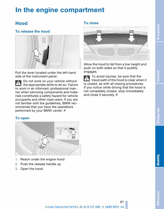
Refe
renc
eAt
a g
lanc
eCo
ntro
lsDr
ivin
g ti
psM
obili
ty
81
In the engine compartment
Hood
To release the hood
Pull the lever located under the left-hand side of the instrument panel.
Do not work on your vehicle without the appropriate skills to do so. Failure
to work in an informed, professional man-ner when servicing components and mate-rials constitutes a safety hazard for vehicle occupants and other road users. If you are not familiar with the guidelines, BMW rec-ommends that you have the operations performed by your BMW center.<
To open
1. Reach under the engine hood
2. Push the release handle up
3. Open the hood.
To close
Allow the hood to fall from a low height and push on both sides so that it audibly engages.
To avoid injuries, be sure that the travel path of the hood is clear when it
is closed, as with all closing procedures.If you notice while driving that the hood is not completely closed, stop immediately and close it securely.<
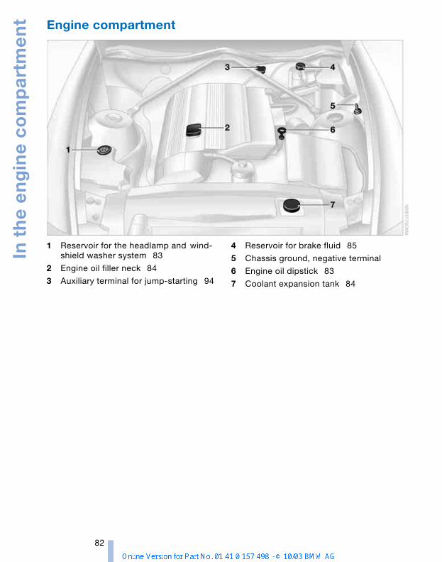
In t
he
en
gin
e c
om
par
tme
nt
82
Engine compartment
1 Reservoir for the headlamp and wind-shield washer system 83
2 Engine oil filler neck 84
3 Auxiliary terminal for jump-starting 94
4 Reservoir for brake fluid 85
5 Chassis ground, negative terminal
6 Engine oil dipstick 83
7 Coolant expansion tank 84
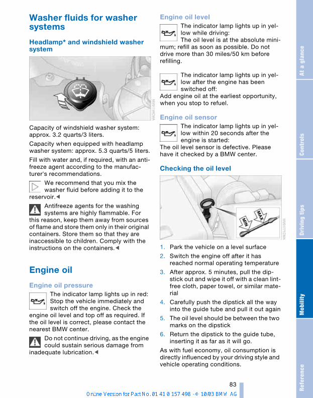
Refe
renc
eAt
a g
lanc
eCo
ntro
lsDr
ivin
g ti
psM
obili
ty
83
Washer fluids for washer systems
Headlamp* and windshield washer system
Capacity of windshield washer system: approx. 3.2 quarts/3 liters.
Capacity when equipped with headlamp washer system: approx. 5.3 quarts/5 liters.
Fill with water and, if required, with an anti-freeze agent according to the manufac-turer's recommendations.
We recommend that you mix the washer fluid before adding it to the
reservoir.<
Antifreeze agents for the washing systems are highly flammable. For
this reason, keep them away from sources of flame and store them only in their original containers. Store them so that they are inaccessible to children. Comply with the instructions on the containers.<
Engine oil
Engine oil pressure The indicator lamp lights up in red:Stop the vehicle immediately and switch off the engine. Check the
engine oil level and top off as required. If the oil level is correct, please contact the nearest BMW center.
Do not continue driving, as the engine could sustain serious damage from
inadequate lubrication.<
Engine oil level The indicator lamp lights up in yel-low while driving: The oil level is at the absolute mini-
mum; refill as soon as possible. Do not drive more than 30 miles/50 km before refilling.
The indicator lamp lights up in yel-low after the engine has been switched off:
Add engine oil at the earliest opportunity, when you stop to refuel.
Engine oil sensorThe indicator lamp lights up in yel-low within 20 seconds after the engine is started:
The oil level sensor is defective. Please have it checked by a BMW center.
Checking the oil level
1. Park the vehicle on a level surface
2. Switch the engine off after it has reached normal operating temperature
3. After approx. 5 minutes, pull the dip-stick out and wipe it off with a clean lint-free cloth, paper towel, or similar mate-rial
4. Carefully push the dipstick all the way into the guide tube and pull it out again
5. The oil level should be between the two marks on the dipstick
6. Return the dipstick to the guide tube, inserting it as far as it will go.
As with fuel economy, oil consumption is directly influenced by your driving style and vehicle operating conditions.
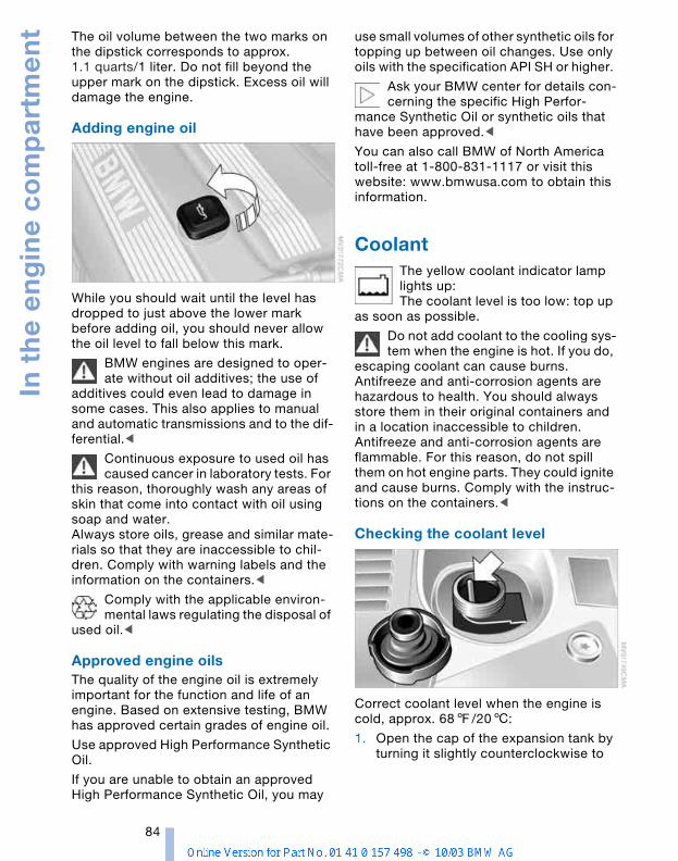
In t
he
en
gin
e c
om
par
tme
nt
84
The oil volume between the two marks on the dipstick corresponds to approx. 1.1 quarts/1 liter. Do not fill beyond the upper mark on the dipstick. Excess oil will damage the engine.
Adding engine oil
While you should wait until the level has dropped to just above the lower mark before adding oil, you should never allow the oil level to fall below this mark.
BMW engines are designed to oper-ate without oil additives; the use of
additives could even lead to damage in some cases. This also applies to manual and automatic transmissions and to the dif-ferential.<
Continuous exposure to used oil has caused cancer in laboratory tests. For
this reason, thoroughly wash any areas of skin that come into contact with oil using soap and water.Always store oils, grease and similar mate-rials so that they are inaccessible to chil-dren. Comply with warning labels and the information on the containers.<
Comply with the applicable environ-mental laws regulating the disposal of
used oil.<
Approved engine oils The quality of the engine oil is extremely important for the function and life of an engine. Based on extensive testing, BMW has approved certain grades of engine oil.
Use approved High Performance Synthetic Oil.
If you are unable to obtain an approved High Performance Synthetic Oil, you may
use small volumes of other synthetic oils for topping up between oil changes. Use only oils with the specification API SH or higher.
Ask your BMW center for details con-cerning the specific High Perfor-
mance Synthetic Oil or synthetic oils that have been approved.<
You can also call BMW of North America toll-free at 1-800-831-1117 or visit this website: www.bmwusa.com to obtain this information.
Coolant The yellow coolant indicator lamp lights up:The coolant level is too low: top up
as soon as possible.
Do not add coolant to the cooling sys-tem when the engine is hot. If you do,
escaping coolant can cause burns.Antifreeze and anti-corrosion agents are hazardous to health. You should always store them in their original containers and in a location inaccessible to children.Antifreeze and anti-corrosion agents are flammable. For this reason, do not spill them on hot engine parts. They could ignite and cause burns. Comply with the instruc-tions on the containers.<
Checking the coolant level
Correct coolant level when the engine is cold, approx. 687/206:
1. Open the cap of the expansion tank by turning it slightly counterclockwise to
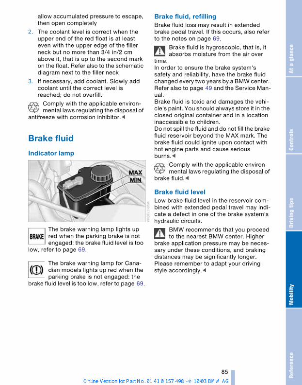
Refe
renc
eAt
a g
lanc
eCo
ntro
lsDr
ivin
g ti
psM
obili
ty
85
allow accumulated pressure to escape, then open completely
2. The coolant level is correct when the upper end of the red float is at least even with the upper edge of the filler neck but no more than 3/4 in/2 cm above it, that is up to the second mark on the float. Refer also to the schematic diagram next to the filler neck
3. If necessary, add coolant. Slowly add coolant until the correct level is reached; do not overfill.
Comply with the applicable environ-mental laws regulating the disposal of
antifreeze with corrosion inhibitor.<
Brake fluid
Indicator lamp
The brake warning lamp lights up red when the parking brake is not engaged: the brake fluid level is too
low, refer to page 69.
The brake warning lamp for Cana-dian models lights up red when the parking brake is not engaged: the
brake fluid level is too low, refer to page 69.
Brake fluid, refilling Brake fluid loss may result in extended brake pedal travel. If this occurs, also refer to the notes on page 69.
Brake fluid is hygroscopic, that is, it absorbs moisture from the air over
time.In order to ensure the brake system's safety and reliability, have the brake fluid changed every two years by a BMW center. Refer also to page 49 and the Service Man-ual.Brake fluid is toxic and damages the vehi-cle's paint. You should always store it in the closed original container and in a location inaccessible to children.Do not spill the fluid and do not fill the brake fluid reservoir beyond the MAX mark. The brake fluid could ignite upon contact with hot engine parts and cause serious burns.<
Comply with the applicable environ-mental laws regulating the disposal of
brake fluid.<
Brake fluid levelLow brake fluid level in the reservoir com-bined with extended pedal travel may indi-cate a defect in one of the brake system's hydraulic circuits.
BMW recommends that you proceed to the nearest BMW center. Higher
brake application pressure may be neces-sary under these conditions, and braking distances may be significantly longer. Please remember to adapt your driving style accordingly.<
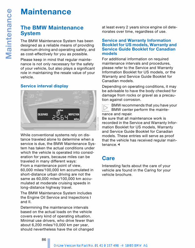
Mai
nte
nan
ce
86
Maintenance
The BMW Maintenance System The BMW Maintenance System has been designed as a reliable means of providing maximum driving and operating safety, and as cost-effectively for you as possible.
Please keep in mind that regular mainte-nance is not only necessary for the safety of your vehicle, but also plays a significant role in maintaining the resale value of your vehicle.
Service interval display
While conventional systems rely on dis-tance traveled alone to determine when a service is due, the BMW Maintenance Sys-tem has taken the actual conditions under which the vehicle is operated into consid-eration for years, because miles can be traveled in many different ways:From a maintenance point of view, 60,000 miles/100,000 km accumulated in short-distance urban driving are not the same as 60,000 miles/100,000 km accu-mulated at moderate cruising speeds in long-distance highway travel.
The BMW Maintenance System includes the Engine Oil Service and Inspections I and II.
Determining the maintenance intervals based on the actual loads on the vehicle covers every kind of operating situation. Minimal use drivers, who drive fewer than about 6,200 miles/10,000 km per year, should nevertheless have the oil changed
at least every 2 years since engine oil dete-riorates over time, regardless of use.
Service and Warranty Information Booklet for US models, Warranty and Service Guide Booklet for Canadian models For additional information on required maintenance intervals and procedures, please refer to the Service and Warranty Information Booklet for US models, or the Warranty and Service Guide Booklet for Canadian models.
Depending on operating conditions, it may be advisable to have the body checked for damage from rocks or gravel as a precau-tion against corrosion.
BMW recommends that you have your BMW center perform the mainte-
nance and repair.Be sure that all maintenance work is recorded in the Service and Warranty Infor-mation Booklet for US models, Warranty and Service Guide Booklet for Canadian models. These entries will serve as proof that the vehicle has received regular main-tenance.<
CareInteresting facts about the care of your vehicle are found in the Caring for your vehicle brochure.
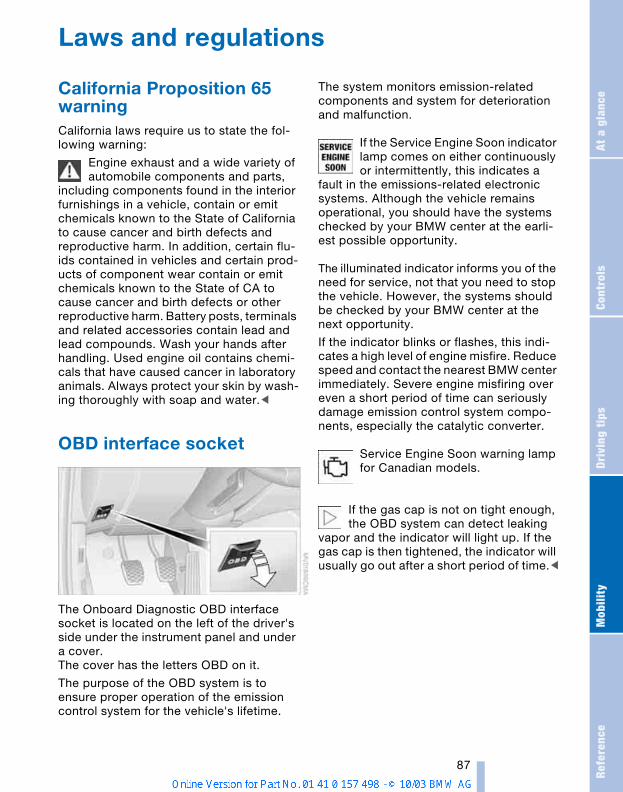
Refe
renc
eAt
a g
lanc
eCo
ntro
lsDr
ivin
g ti
psM
obili
ty
87
Laws and regulations
California Proposition 65 warningCalifornia laws require us to state the fol-lowing warning:
Engine exhaust and a wide variety of automobile components and parts,
including components found in the interior furnishings in a vehicle, contain or emit chemicals known to the State of California to cause cancer and birth defects and reproductive harm. In addition, certain flu-ids contained in vehicles and certain prod-ucts of component wear contain or emit chemicals known to the State of CA to cause cancer and birth defects or other reproductive harm. Battery posts, terminals and related accessories contain lead and lead compounds. Wash your hands after handling. Used engine oil contains chemi-cals that have caused cancer in laboratory animals. Always protect your skin by wash-ing thoroughly with soap and water.<
OBD interface socket
The Onboard Diagnostic OBD interface socket is located on the left of the driver's side under the instrument panel and under a cover.The cover has the letters OBD on it.
The purpose of the OBD system is to ensure proper operation of the emission control system for the vehicle's lifetime.
The system monitors emission-related components and system for deterioration and malfunction.
If the Service Engine Soon indicator lamp comes on either continuously or intermittently, this indicates a
fault in the emissions-related electronic systems. Although the vehicle remains operational, you should have the systems checked by your BMW center at the earli-est possible opportunity.
The illuminated indicator informs you of the need for service, not that you need to stop the vehicle. However, the systems should be checked by your BMW center at the next opportunity.
If the indicator blinks or flashes, this indi-cates a high level of engine misfire. Reduce speed and contact the nearest BMW center immediately. Severe engine misfiring over even a short period of time can seriously damage emission control system compo-nents, especially the catalytic converter.
Service Engine Soon warning lamp for Canadian models.
If the gas cap is not on tight enough, the OBD system can detect leaking
vapor and the indicator will light up. If the gas cap is then tightened, the indicator will usually go out after a short period of time.<
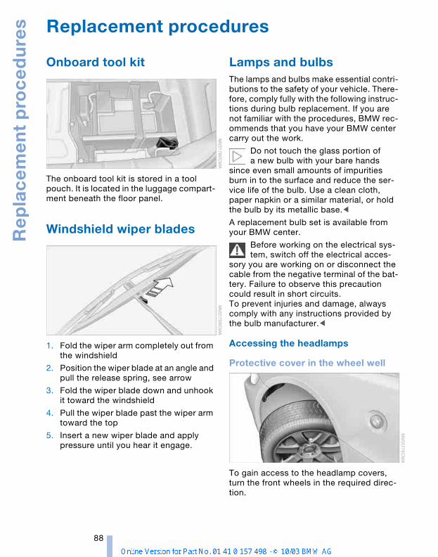
Re
pla
ce
me
nt
pro
ce
du
res
88
Replacement procedures
Onboard tool kit
The onboard tool kit is stored in a tool pouch. It is located in the luggage compart-ment beneath the floor panel.
Windshield wiper blades
1. Fold the wiper arm completely out from the windshield
2. Position the wiper blade at an angle and pull the release spring, see arrow
3. Fold the wiper blade down and unhook it toward the windshield
4. Pull the wiper blade past the wiper arm toward the top
5. Insert a new wiper blade and apply pressure until you hear it engage.
Lamps and bulbs The lamps and bulbs make essential contri-butions to the safety of your vehicle. There-fore, comply fully with the following instruc-tions during bulb replacement. If you are not familiar with the procedures, BMW rec-ommends that you have your BMW center carry out the work.
Do not touch the glass portion of a new bulb with your bare hands
since even small amounts of impurities burn in to the surface and reduce the ser-vice life of the bulb. Use a clean cloth, paper napkin or a similar material, or hold the bulb by its metallic base.<
A replacement bulb set is available from your BMW center.
Before working on the electrical sys-tem, switch off the electrical acces-
sory you are working on or disconnect the cable from the negative terminal of the bat-tery. Failure to observe this precaution could result in short circuits.To prevent injuries and damage, always comply with any instructions provided by the bulb manufacturer.<
Accessing the headlamps
Protective cover in the wheel well
To gain access to the headlamp covers, turn the front wheels in the required direc-tion.
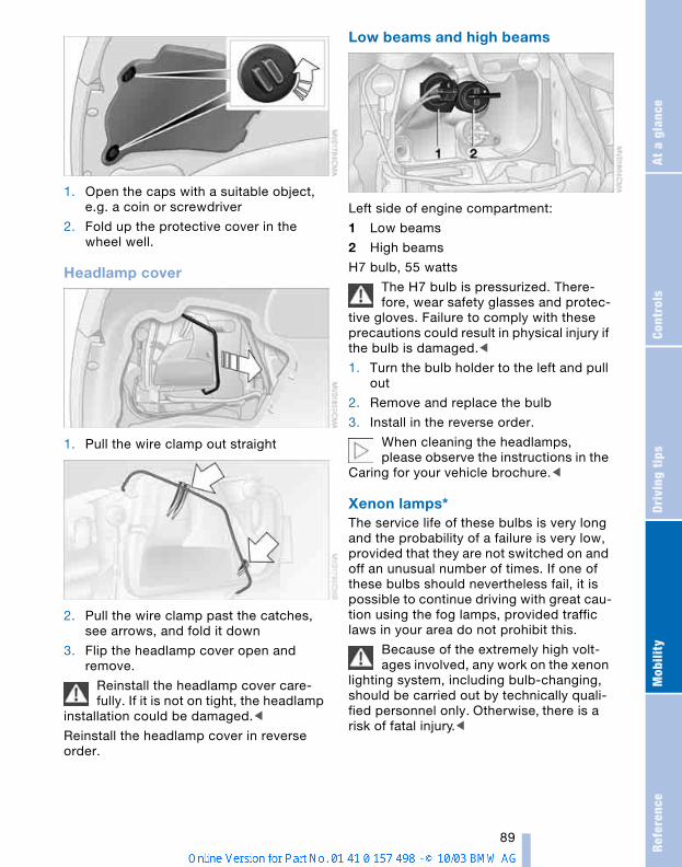
Refe
renc
eAt
a g
lanc
eCo
ntro
lsDr
ivin
g ti
psM
obili
ty
89
1. Open the caps with a suitable object, e.g. a coin or screwdriver
2. Fold up the protective cover in the wheel well.
Headlamp cover
1. Pull the wire clamp out straight
2. Pull the wire clamp past the catches, see arrows, and fold it down
3. Flip the headlamp cover open and remove.
Reinstall the headlamp cover care-fully. If it is not on tight, the headlamp
installation could be damaged.<
Reinstall the headlamp cover in reverse order.
Low beams and high beams
Left side of engine compartment:
1 Low beams
2 High beams
H7 bulb, 55 watts
The H7 bulb is pressurized. There-fore, wear safety glasses and protec-
tive gloves. Failure to comply with these precautions could result in physical injury if the bulb is damaged.<
1. Turn the bulb holder to the left and pull out
2. Remove and replace the bulb
3. Install in the reverse order.
When cleaning the headlamps, please observe the instructions in the
Caring for your vehicle brochure.<
Xenon lamps* The service life of these bulbs is very long and the probability of a failure is very low, provided that they are not switched on and off an unusual number of times. If one of these bulbs should nevertheless fail, it is possible to continue driving with great cau-tion using the fog lamps, provided traffic laws in your area do not prohibit this.
Because of the extremely high volt-ages involved, any work on the xenon
lighting system, including bulb-changing, should be carried out by technically quali-fied personnel only. Otherwise, there is a risk of fatal injury.<
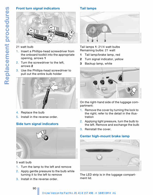
Re
pla
ce
me
nt
pro
ce
du
res
90
Front turn signal indicators
21 watt bulb
1. Insert a Phillips-head screwdriver from the onboard toolkit into the appropriate opening, arrows 1
2. Turn the screwdriver to the left, arrows 2
3. Use the Phillips-head screwdriver to pull out the entire bulb holder
4. Replace the bulb
5. Install in the reverse order.
Side turn signal indicators
5 watt bulb
1. Turn the lamp to the left and remove
2. Apply gentle pressure to the bulb while turning it to the left to remove
3. Install in the reverse order.
Tail lamps
Tail lamps 1: 21/4 watt bulbs Remaining bulbs: 21 watt
1 Tail lamp/brake lamp, red
2 Turn signal indicator, yellow
3 Backup lamp, white
On the right-hand side of the luggage com-partment:
1. Remove the cover by turning the lock to the right; refer to the detail in the illus-tration
2. Applying light pressure, turn the bulb to the left. Remove and exchange the bulb
3. Reinstall the cover.
Center high-mount brake lamp
The LED strip is in the luggage compart-ment lid.
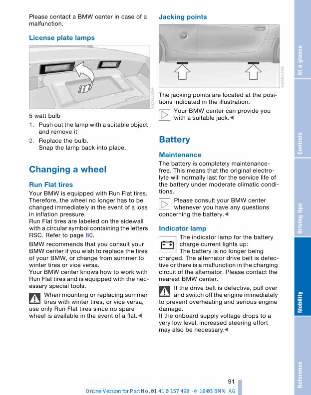
Refe
renc
eAt
a g
lanc
eCo
ntro
lsDr
ivin
g ti
psM
obili
ty
91
Please contact a BMW center in case of a malfunction.
License plate lamps
5 watt bulb
1. Push out the lamp with a suitable object and remove it
2. Replace the bulb.Snap the lamp back into place.
Changing a wheel
Run Flat tiresYour BMW is equipped with Run Flat tires. Therefore, the wheel no longer has to be changed immediately in the event of a loss in inflation pressure.Run Flat tires are labeled on the sidewall with a circular symbol containing the letters RSC. Refer to page 80.
BMW recommends that you consult your BMW center if you wish to replace the tires of your BMW, or change from summer to winter tires or vice versa. Your BMW center knows how to work with Run Flat tires and is equipped with the nec-essary special tools.
When mounting or replacing summer tires with winter tires, or vice versa,
use only Run Flat tires since no spare wheel is available in the event of a flat.<
Jacking points
The jacking points are located at the posi-tions indicated in the illustration.
Your BMW center can provide you with a suitable jack.<
Battery
MaintenanceThe battery is completely maintenance-free. This means that the original electro-lyte will normally last for the service life of the battery under moderate climatic condi-tions.
Please consult your BMW center whenever you have any questions
concerning the battery.<
Indicator lamp The indicator lamp for the battery charge current lights up:The battery is no longer being
charged. The alternator drive belt is defec-tive or there is a malfunction in the charging circuit of the alternator. Please contact the nearest BMW center.
If the drive belt is defective, pull over and switch off the engine immediately
to prevent overheating and serious engine damage. If the onboard supply voltage drops to a very low level, increased steering effort may also be necessary.<
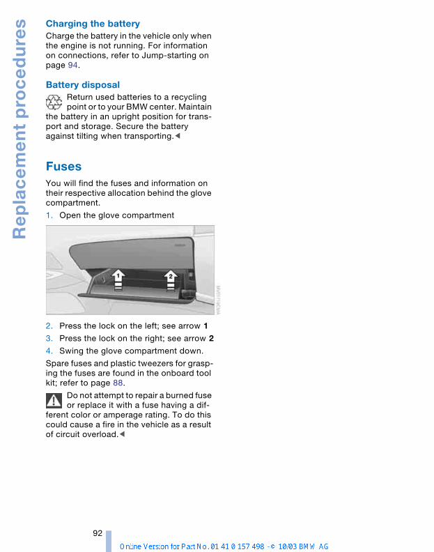
Re
pla
ce
me
nt
pro
ce
du
res
92
Charging the batteryCharge the battery in the vehicle only when the engine is not running. For information on connections, refer to Jump-starting on page 94.
Battery disposalReturn used batteries to a recycling point or to your BMW center. Maintain
the battery in an upright position for trans-port and storage. Secure the battery against tilting when transporting.<
Fuses You will find the fuses and information on their respective allocation behind the glove compartment.
1. Open the glove compartment
2. Press the lock on the left; see arrow 1
3. Press the lock on the right; see arrow 2
4. Swing the glove compartment down.
Spare fuses and plastic tweezers for grasp-ing the fuses are found in the onboard tool kit; refer to page 88.
Do not attempt to repair a burned fuse or replace it with a fuse having a dif-
ferent color or amperage rating. To do this could cause a fire in the vehicle as a result of circuit overload.<
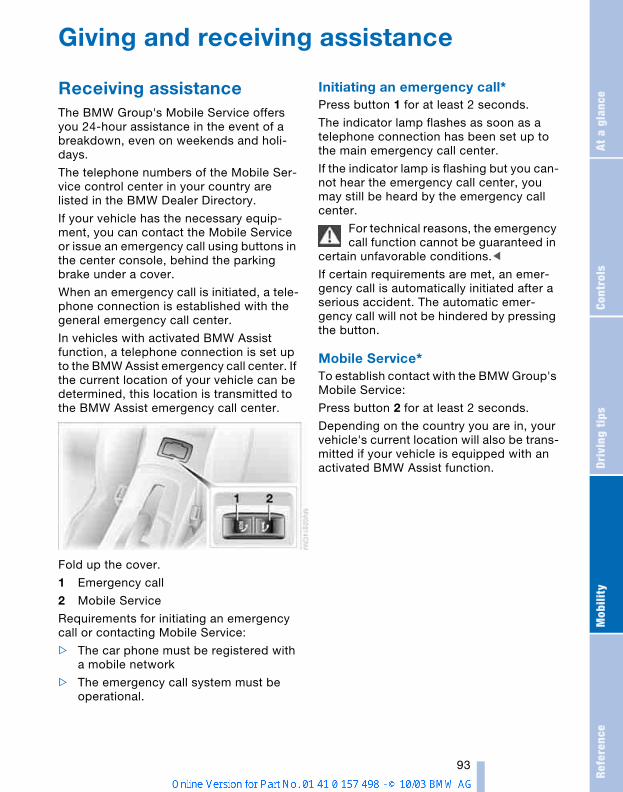
Refe
renc
eAt
a g
lanc
eCo
ntro
lsDr
ivin
g ti
psM
obili
ty
93
Giving and receiving assistance
Receiving assistanceThe BMW Group's Mobile Service offers you 24-hour assistance in the event of a breakdown, even on weekends and holi-days.
The telephone numbers of the Mobile Ser-vice control center in your country are listed in the BMW Dealer Directory.
If your vehicle has the necessary equip-ment, you can contact the Mobile Service or issue an emergency call using buttons in the center console, behind the parking brake under a cover.
When an emergency call is initiated, a tele-phone connection is established with the general emergency call center.
In vehicles with activated BMW Assist function, a telephone connection is set up to the BMW Assist emergency call center. If the current location of your vehicle can be determined, this location is transmitted to the BMW Assist emergency call center.
Fold up the cover.
1 Emergency call
2 Mobile Service
Requirements for initiating an emergency call or contacting Mobile Service:
> The car phone must be registered with a mobile network
> The emergency call system must be operational.
Initiating an emergency call* Press button 1 for at least 2 seconds.
The indicator lamp flashes as soon as a telephone connection has been set up to the main emergency call center.
If the indicator lamp is flashing but you can-not hear the emergency call center, you may still be heard by the emergency call center.
For technical reasons, the emergency call function cannot be guaranteed in
certain unfavorable conditions.<
If certain requirements are met, an emer-gency call is automatically initiated after a serious accident. The automatic emer-gency call will not be hindered by pressing the button.
Mobile Service* To establish contact with the BMW Group's Mobile Service:
Press button 2 for at least 2 seconds.
Depending on the country you are in, your vehicle's current location will also be trans-mitted if your vehicle is equipped with an activated BMW Assist function.
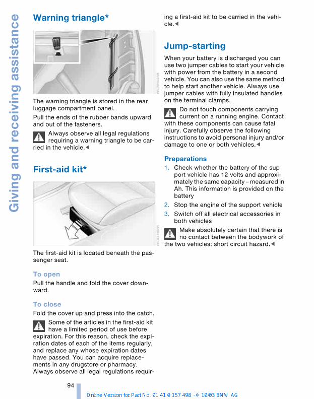
Giv
ing
an
d r
ec
eiv
ing
ass
ista
nc
e
94
Warning triangle*
The warning triangle is stored in the rear luggage compartment panel.
Pull the ends of the rubber bands upward and out of the fasteners.
Always observe all legal regulations requiring a warning triangle to be car-
ried in the vehicle.<
First-aid kit*
The first-aid kit is located beneath the pas-senger seat.
To openPull the handle and fold the cover down-ward.
To closeFold the cover up and press into the catch.
Some of the articles in the first-aid kit have a limited period of use before
expiration. For this reason, check the expi-ration dates of each of the items regularly, and replace any whose expiration dates have passed. You can acquire replace-ments in any drugstore or pharmacy.Always observe all legal regulations requir-
ing a first-aid kit to be carried in the vehi-cle.<
Jump-starting When your battery is discharged you can use two jumper cables to start your vehicle with power from the battery in a second vehicle. You can also use the same method to help start another vehicle. Always use jumper cables with fully insulated handles on the terminal clamps.
Do not touch components carrying current on a running engine. Contact
with these components can cause fatal injury. Carefully observe the following instructions to avoid personal injury and/or damage to one or both vehicles.<
Preparations1. Check whether the battery of the sup-
port vehicle has 12 volts and approxi-mately the same capacity – measured in Ah. This information is provided on the battery
2. Stop the engine of the support vehicle
3. Switch off all electrical accessories in both vehicles
Make absolutely certain that there is no contact between the bodywork of
the two vehicles: short circuit hazard.<
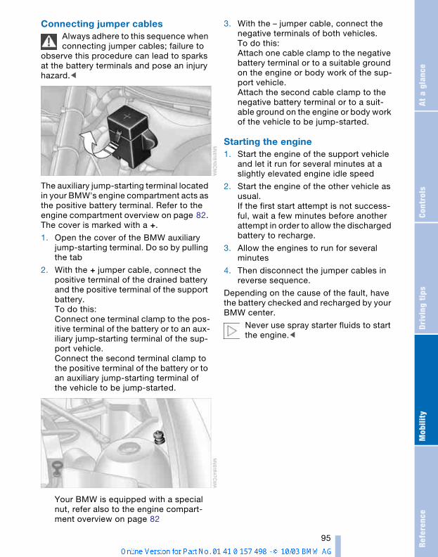
Refe
renc
eAt
a g
lanc
eCo
ntro
lsDr
ivin
g ti
psM
obili
ty
95
Connecting jumper cablesAlways adhere to this sequence when connecting jumper cables; failure to
observe this procedure can lead to sparks at the battery terminals and pose an injury hazard.<
The auxiliary jump-starting terminal located in your BMW's engine compartment acts as the positive battery terminal. Refer to the engine compartment overview on page 82. The cover is marked with a +.
1. Open the cover of the BMW auxiliary jump-starting terminal. Do so by pulling the tab
2. With the + jumper cable, connect the positive terminal of the drained battery and the positive terminal of the support battery.To do this:Connect one terminal clamp to the pos-itive terminal of the battery or to an aux-iliary jump-starting terminal of the sup-port vehicle.Connect the second terminal clamp to the positive terminal of the battery or to an auxiliary jump-starting terminal of the vehicle to be jump-started.
Your BMW is equipped with a special nut, refer also to the engine compart-ment overview on page 82
3. With the – jumper cable, connect the negative terminals of both vehicles. To do this:Attach one cable clamp to the negative battery terminal or to a suitable ground on the engine or body work of the sup-port vehicle.Attach the second cable clamp to the negative battery terminal or to a suit-able ground on the engine or body work of the vehicle to be jump-started.
Starting the engine1. Start the engine of the support vehicle
and let it run for several minutes at a slightly elevated engine idle speed
2. Start the engine of the other vehicle as usual. If the first start attempt is not success-ful, wait a few minutes before another attempt in order to allow the discharged battery to recharge.
3. Allow the engines to run for several minutes
4. Then disconnect the jumper cables in reverse sequence.
Depending on the cause of the fault, have the battery checked and recharged by your BMW center.
Never use spray starter fluids to start the engine.<
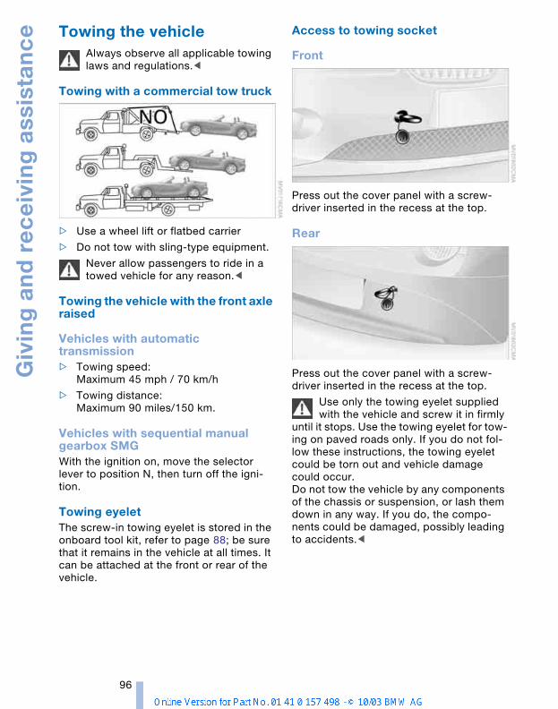
Giv
ing
an
d r
ec
eiv
ing
ass
ista
nc
e
96
Towing the vehicle Always observe all applicable towing laws and regulations.<
Towing with a commercial tow truck
> Use a wheel lift or flatbed carrier
> Do not tow with sling-type equipment.
Never allow passengers to ride in a towed vehicle for any reason.<
Towing the vehicle with the front axle raised
Vehicles with automatic transmission> Towing speed:
Maximum 45 mph / 70 km/h
> Towing distance: Maximum 90 miles/150 km.
Vehicles with sequential manual gearbox SMGWith the ignition on, move the selector lever to position N, then turn off the igni-tion.
Towing eyelet The screw-in towing eyelet is stored in the onboard tool kit, refer to page 88; be sure that it remains in the vehicle at all times. It can be attached at the front or rear of the vehicle.
Access to towing socket
Front
Press out the cover panel with a screw-driver inserted in the recess at the top.
Rear
Press out the cover panel with a screw-driver inserted in the recess at the top.
Use only the towing eyelet supplied with the vehicle and screw it in firmly
until it stops. Use the towing eyelet for tow-ing on paved roads only. If you do not fol-low these instructions, the towing eyelet could be torn out and vehicle damage could occur. Do not tow the vehicle by any components of the chassis or suspension, or lash them down in any way. If you do, the compo-nents could be damaged, possibly leading to accidents.<

Refe
renc
eAt
a g
lanc
eCo
ntro
lsDr
ivin
g ti
psM
obili
ty
97

ReferenceThis chapter will help you find the desired
information as quickly as possible.It contains the Technical data section as
well as the manual's index.
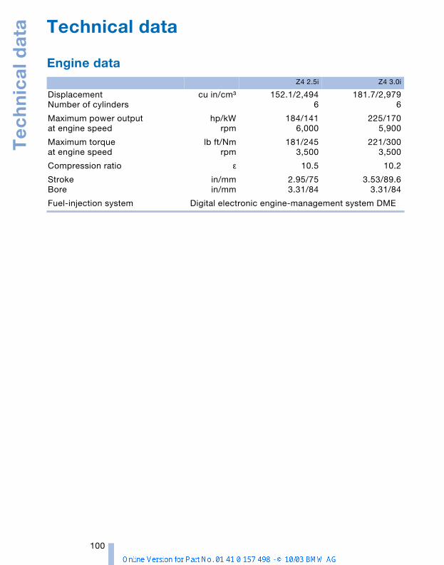
Te
ch
nic
al d
ata
100
Technical data
Engine data Z4 2.5i Z4 3.0i
DisplacementNumber of cylinders
cu in/cmµ 152.1/2,4946
181.7/2,9796
Maximum power output at engine speed
hp/kWrpm
184/1416,000
225/1705,900
Maximum torque at engine speed
lb ft/Nmrpm
181/2453,500
221/3003,500
Compression ratio ε 10.5 10.2
StrokeBore
in/mmin/mm
2.95/753.31/84
3.53/89.63.31/84
Fuel-injection system Digital electronic engine-management system DME
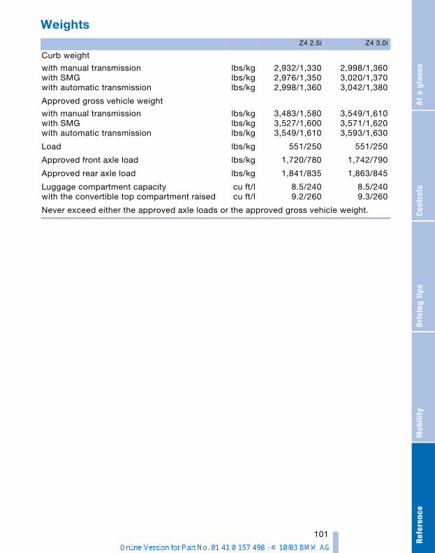
Refe
renc
eAt
a g
lanc
eCo
ntro
lsDr
ivin
g ti
psM
obili
ty
101
Weights Z4 2.5i Z4 3.0i
Curb weight
with manual transmissionwith SMGwith automatic transmission
lbs/kglbs/kglbs/kg
2,932/1,3302,976/1,3502,998/1,360
2,998/1,3603,020/1,3703,042/1,380
Approved gross vehicle weight
with manual transmissionwith SMGwith automatic transmission
lbs/kglbs/kglbs/kg
3,483/1,5803,527/1,6003,549/1,610
3,549/1,6103,571/1,6203,593/1,630
Load lbs/kg 551/250 551/250
Approved front axle load lbs/kg 1,720/780 1,742/790
Approved rear axle load lbs/kg 1,841/835 1,863/845
Luggage compartment capacity with the convertible top compartment raised
cu ft/lcu ft/l
8.5/2409.2/260
8.5/2409.3/260
Never exceed either the approved axle loads or the approved gross vehicle weight.
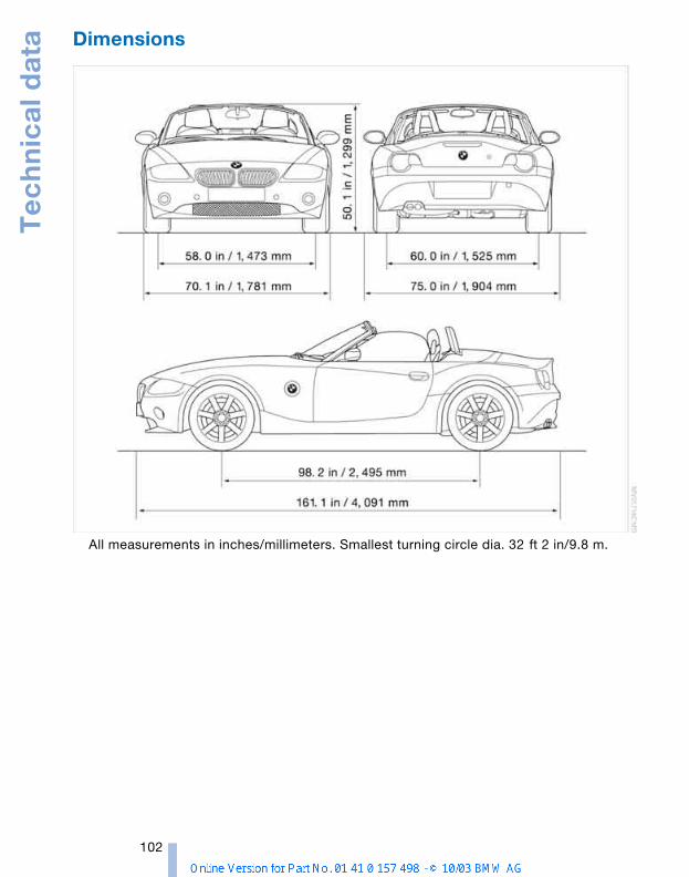
Te
ch
nic
al d
ata
102
Dimensions
All measurements in inches/millimeters. Smallest turning circle dia. 32 ft 2 in/9.8 m.
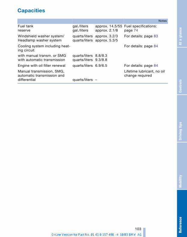
Refe
renc
eAt
a g
lanc
eCo
ntro
lsDr
ivin
g ti
psM
obili
ty
103
Capacities
Notes
Fuel tank reserve
gal./litersgal./liters
approx. 14.5/55approx. 2.1/8
Fuel specifications: page 74
Windshield washer system/Headlamp washer system
quarts/litersquarts/liters
approx. 3.2/3 approx. 5.3/5
For details: page 83
Cooling system including heat-ing circuit
with manual transm. or SMGwith automatic transmission
quarts/litersquarts/liters
8.8/8.39.3/8.8
For details: page 84
Engine with oil filter renewal quarts/liters 6.9/6.5 For details: page 84
Manual transmission, SMG, automatic transmission and differential quarts/liters –
Lifetime lubricant, no oil change required
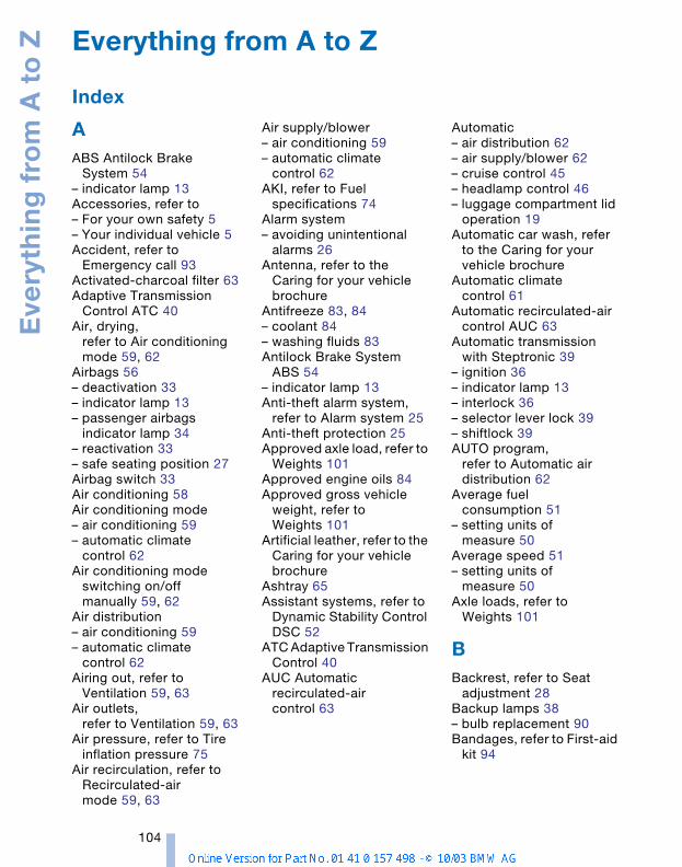
Eve
ryth
ing
fro
m A
to
Z
104
AABS Antilock Brake
System 54– indicator lamp 13Accessories, refer to– For your own safety 5– Your individual vehicle 5Accident, refer to
Emergency call 93Activated-charcoal filter 63Adaptive Transmission
Control ATC 40Air, drying,
refer to Air conditioning mode 59, 62
Airbags 56– deactivation 33– indicator lamp 13– passenger airbags
indicator lamp 34– reactivation 33– safe seating position 27Airbag switch 33Air conditioning 58Air conditioning mode– air conditioning 59– automatic climate
control 62Air conditioning mode
switching on/off manually 59, 62
Air distribution– air conditioning 59– automatic climate
control 62Airing out, refer to
Ventilation 59, 63Air outlets,
refer to Ventilation 59, 63Air pressure, refer to Tire
inflation pressure 75Air recirculation, refer to
Recirculated-air mode 59, 63
Air supply/blower– air conditioning 59– automatic climate
control 62AKI, refer to Fuel
specifications 74Alarm system– avoiding unintentional
alarms 26Antenna, refer to the
Caring for your vehicle brochure
Antifreeze 83, 84– coolant 84– washing fluids 83Antilock Brake System
ABS 54– indicator lamp 13Anti-theft alarm system,
refer to Alarm system 25Anti-theft protection 25Approved axle load, refer to
Weights 101Approved engine oils 84Approved gross vehicle
weight, refer to Weights 101
Artificial leather, refer to the Caring for your vehicle brochure
Ashtray 65Assistant systems, refer to
Dynamic Stability Control DSC 52
ATC Adaptive Transmission Control 40
AUC Automatic recirculated-air control 63
Automatic– air distribution 62– air supply/blower 62– cruise control 45– headlamp control 46– luggage compartment lid
operation 19Automatic car wash, refer
to the Caring for your vehicle brochure
Automatic climate control 61
Automatic recirculated-air control AUC 63
Automatic transmission with Steptronic 39
– ignition 36– indicator lamp 13– interlock 36– selector lever lock 39– shiftlock 39AUTO program,
refer to Automatic air distribution 62
Average fuel consumption 51
– setting units of measure 50
Average speed 51– setting units of
measure 50Axle loads, refer to
Weights 101
BBackrest, refer to Seat
adjustment 28Backup lamps 38– bulb replacement 90Bandages, refer to First-aid
kit 94
Everything from A to Z
Index

Refe
renc
eAt
a g
lanc
eCo
ntro
lsDr
ivin
g ti
psM
obili
ty
105
Battery 91– disposal 92– indicator lamp 13, 91– jump-starting 94– remote control 17Belts, refer to Safety
belts 30Belt tensioner, refer to
Safety belts 30Beverage holders 65Blower– air conditioning 59– automatic climate
control 62Blower, refer to Air
supply 59, 62BMW 5Bore, refer to Engine
data 100Bottle holders, refer to
Beverage holders 65Brake fluid 85– filling 85– indicator/warning
lamp 13, 85– level 85Brake force display 53Brake hydraulic system 85– indicator/warning
lamp 13, 69, 85Brake lamps– bulb replacement 90– indicator lamp, defective
lamp 13Brake pads 70– break-in procedures 68– indicator lamp 70Brake pad wear indicator– brake pads 70– indicator lamp 13Brake rotors– brake system 69– break-in procedures 68Brakes 69– ABS 54– brake fluid 85– break-in procedures 68– indicator/warning
lamps 13, 52, 53, 54– parking brake 38
Brake system 69– brake fluid level 85– brake pads 70– break-in procedures 68– disc brakes 69– indicator lamp 13Breakdown– Flat Tire Monitor 54Break-in procedures 68Bulb replacement, refer to
Lamps and bulbs 88Buttons in steering
wheel 11
CCalifornia Proposition
65 warning 87Can holders, refer to
Beverage holders 65Capacities 103Car battery 91Car care, refer to the Caring
for your vehicle brochureCar-care products, refer to
the Caring for your vehicle brochure
Care, refer to the Caring for your vehicle brochure
Cargo loading– vehicle 70Car keys, refer to Keys 16Carpet care, refer to the
Caring for your vehicle brochure
Car radio, refer to Owner's Manual for Radio
Car telephone, refer to Owner's Manual for Telephone
Car wash, refer to the Caring for your vehicle brochure
Catalytic converter, refer to High temperatures 69
CD player operation, refer to Owner's Manualfor Radio
Center high-mount brake lamp
– bulb replacement 90
Central locking system 16– interior 18Changing a wheel 91Charge indicator
lamp 13, 91Check Gas Cap– indicator lamp 13Child-restraint mounting
system, LATCH 35Child-restraint systems 33Child seat, refer to Child-
restraint systems 33Chrome parts, refer to the
Caring for your vehicle brochure
Cigarette lighter 65Cigarette lighter socket 65Cleaning the rear window,
refer to the Caring for your vehicle brochure
Cleaning the vehicle, refer to the Caring for your vehicle brochure
Cleaning the windshield 44Clock 49, 50– 12- or 24-hour mode 50– refer to Owner's Manual
for Radio/Onboard Computer
– setting 49Clothes hooks 25Clutch– break-in procedures 68Cockpit 10Cold start, refer to
Starting the engine 36Compact disc operation,
refer to Owner's Manual for Radio
Compartments 64Compression ratio, refer to
Engine data 100Computer 50– clock, 12- or 24-hour
mode 50– refer to Owner's Manual
for Onboard ComputerComputer, refer to
Onboard Computer 50Condensation, refer to Air
conditioning mode 59, 62
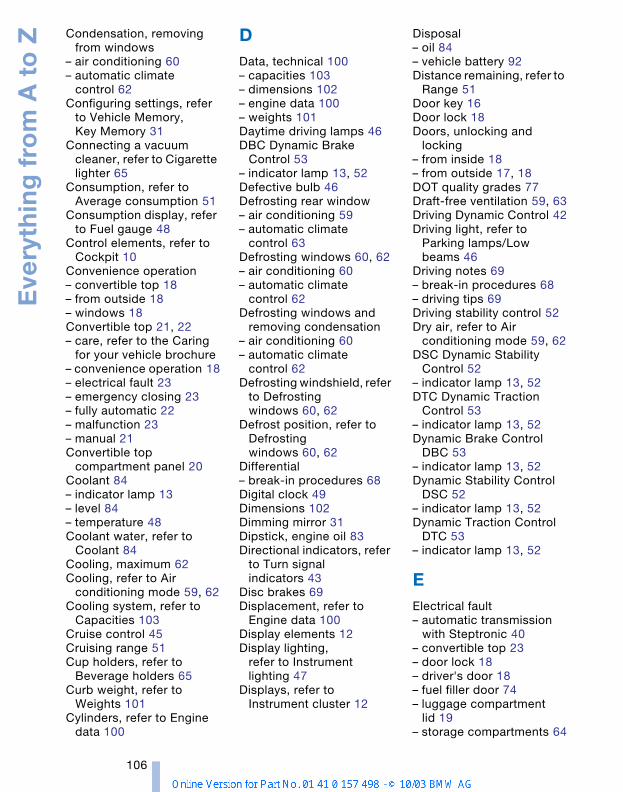
Eve
ryth
ing
fro
m A
to
Z
106
Condensation, removing from windows
– air conditioning 60– automatic climate
control 62Configuring settings, refer
to Vehicle Memory, Key Memory 31
Connecting a vacuum cleaner, refer to Cigarette lighter 65
Consumption, refer to Average consumption 51
Consumption display, refer to Fuel gauge 48
Control elements, refer to Cockpit 10
Convenience operation– convertible top 18– from outside 18– windows 18Convertible top 21, 22– care, refer to the Caring
for your vehicle brochure– convenience operation 18– electrical fault 23– emergency closing 23– fully automatic 22– malfunction 23– manual 21Convertible top
compartment panel 20Coolant 84– indicator lamp 13– level 84– temperature 48Coolant water, refer to
Coolant 84Cooling, maximum 62Cooling, refer to Air
conditioning mode 59, 62Cooling system, refer to
Capacities 103Cruise control 45Cruising range 51Cup holders, refer to
Beverage holders 65Curb weight, refer to
Weights 101Cylinders, refer to Engine
data 100
DData, technical 100– capacities 103– dimensions 102– engine data 100– weights 101Daytime driving lamps 46DBC Dynamic Brake
Control 53– indicator lamp 13, 52Defective bulb 46Defrosting rear window– air conditioning 59– automatic climate
control 63Defrosting windows 60, 62– air conditioning 60– automatic climate
control 62Defrosting windows and
removing condensation– air conditioning 60– automatic climate
control 62Defrosting windshield, refer
to Defrosting windows 60, 62
Defrost position, refer to Defrosting windows 60, 62
Differential– break-in procedures 68Digital clock 49Dimensions 102Dimming mirror 31Dipstick, engine oil 83Directional indicators, refer
to Turn signal indicators 43
Disc brakes 69Displacement, refer to
Engine data 100Display elements 12Display lighting,
refer to Instrument lighting 47
Displays, refer to Instrument cluster 12
Disposal– oil 84– vehicle battery 92Distance remaining, refer to
Range 51Door key 16Door lock 18Doors, unlocking and
locking– from inside 18– from outside 17, 18DOT quality grades 77Draft-free ventilation 59, 63Driving Dynamic Control 42Driving light, refer to
Parking lamps/Low beams 46
Driving notes 69– break-in procedures 68– driving tips 69Driving stability control 52Dry air, refer to Air
conditioning mode 59, 62DSC Dynamic Stability
Control 52– indicator lamp 13, 52DTC Dynamic Traction
Control 53– indicator lamp 13, 52Dynamic Brake Control
DBC 53– indicator lamp 13, 52Dynamic Stability Control
DSC 52– indicator lamp 13, 52Dynamic Traction Control
DTC 53– indicator lamp 13, 52
EElectrical fault– automatic transmission
with Steptronic 40– convertible top 23– door lock 18– driver's door 18– fuel filler door 74– luggage compartment
lid 19– storage compartments 64
Refe
renc
eAt
a g
lanc
eCo
ntro
lsDr
ivin
g ti
psM
obili
ty
107
Electric Power Steering EPS 43
– indicator lamp 13Electric power windows 20Electronic Stability
Program ESP, refer to Dynamic Stability Control DSC 52
Electronic transmission control module 40
Emergency call 93Emergency operation, refer
to Manual operation– convertible top 23– driver's door 18– fuel filler door 74– storage compartments 64Engine 36– break-in procedures 68– data 100– electronics 13– indicator lamp 13– speed 48– starting 36– switching off 37Engine compartment 82Engine coolant 84Engine coolant
temperature gauge 48Engine data 100Engine oil 83– alternative oils 84– approved oils 84– capacity 103– indicator lamp 13Engine oil level 83– indicator lamp 13Engine oil pressure 83– indicator lamp 13Engine oil sensor 83– indicator lamp 13Engine output, refer to
Engine data 100Engine speed, refer to
Engine data 100EPS Electric Power
Steering 43Equipment range, see
Service and Warranty Information Booklet for
US models, Warranty and Service Guide Booklet for Canadian models
ESP Electronic Stability Program, refer to Dynamic Stability Control DSC 52
Exhaust system, refer to High temperatures 69
Exterior mirrors 31– automatic dimming
feature 31Eyelet, towing 96
FFalse alarm, stopping
alarm 26Fasten safety belts 30– warning lamp 13, 30Filter, refer to– Microfilter 59– Microfilter/activated-
charcoal filter 63Fine wood, refer to the
Caring for your vehicle brochure
First aid, refer to First-aid kit 94
First-aid kit 94Flat tire– Flat Tire Monitor 54– indicator/warning
lamp 13Flat tire, refer to Tire
condition 78Flat Tire Monitor 54– indicator lamp 13, 55– initializing 55Flooding, refer to Driving
through water 69Floor covers, carpets, refer
to the Caring for your vehicle brochure
Floor mats, refer to the Caring for your vehicle brochure
Fluid reservoir– washing systems 83Fog lamps 47– indicator lamp 13
Follow me home lamps 46Footbrake, refer to Driving
notes 69Front airbags 56Front turn signal indicators– bulb replacement 90Fuel– average
consumption 51– content, refer to
Capacities 103– display 48– preparation, refer to
Engine data 100– quality 74Fuel display, refer to Fuel
gauge 48Fuel filler door 74– unlocking in case of
electrical fault 74Fuel gas cap 74Fuel tank capacity, refer to
Capacities 103Fuses 92
GGasoline, refer to Fuel
quality 74Gasoline gauge, refer to
Fuel gauge 48Gear indicator 40Gear lever– automatic transmission
with Steptronic 39– manual transmission 38Glove compartment 64Gross weight, refer to
Weights 101
HHandbrake, refer to Parking
brake 38Hands-free microphone,
refer to Preparations for the cellular phone 65
Hands-free system 65Hardtop, refer to the
separate Owner's ManualHardtop preparation 71
Eve
ryth
ing
fro
m A
to
Z
108
Hazard warning flashers 10Headlamp cover, care,
refer to the Caring for your vehicle brochure
Headlamp flasher 43– indicator lamp 13Headlamps– bulb replacement 88– care, refer to the Caring
for your vehicle brochure– cleaning 44Headlamps, automatic
control 46Headlamp washer
reservoir 83– content, refer to
Capacities 103Headlamp washer
system– cleaning the
headlamps 44– washing fluids 83Head restraints 28Heated mirrors 31Heated seats 30Heating 58– exterior mirrors 31– rear window 59, 63– seats 30Heavy loads, refer to
Stowing cargo 70Height, refer to
Dimensions 102Height adjustment– seats 28– steering wheel 30High beams 47– bulb replacement 89– headlamp flasher 43– indicator lamp 13High Performance
Synthetic Oil 84– alternative oils 84– approved oils 84High temperatures 69Holders for beverages 65Hood 81Horn 10Hydraulic Brake Assistant,
refer to Dynamic Brake Control DBC 52
Hydraulics– brakes 85Hydroplaning 69
IIce warning 50Identification mark– Run Flat tires 80Ignition 36Ignition key 16Ignition lock 36Inclines 69Index 104Indicator/warning lamp– airbags 57– alarm system 26– brakes 13– coolant temperature 49– DSC 52– engine temperature 48– Flat Tire Monitor 55– fog lamps 47– passenger airbags 34– please fasten safety
belts 30– reserve 48Indicator and warning
lamps, overview 12Individual air
distribution 59, 62Individual settings, refer to
Vehicle Memory, Key Memory 31
Inflation pressure, tires 75Inflation pressure
monitoring, refer to Flat Tire Monitor 54
INSPECTION 49Instrument cluster 12Instrument lighting 47Instrument panel, refer to
Cockpit 10Interior lamps 47– remote control 17Interior motion sensor 26Interior rearview mirror 31– automatic dimming
feature 31Interior temperature– adjusting 59, 62
Interlock, refer to Steering lock 36
Intermittent– operation, wipers 44Interval– display, service 49
JJack 91Jacking points 91Jets, refer to
Ventilation 59, 63Jump-starting 94
KKey Memory 31Keys 16Key switch for passenger
airbags 33Kickdown 39Knock control 74
LLamps 46Lamps and bulbs 88LATCH, child-restraint
mounting system 35Leather care, refer to the
Caring for your vehicle brochure
Length, refer to Dimensions 102
License plate lamps– bulb replacement 91Light-alloy wheels, care,
refer to the Caring for your vehicle brochure
Lighter 65Lighting– of the instruments 47Lighting of the instruments,
refer to Instrument lighting 47
LIGHTS ON warning 46Light switch 46Loads, refer to Cargo
loading 70Loads, securing 70

Refe
renc
eAt
a g
lanc
eCo
ntro
lsDr
ivin
g ti
psM
obili
ty
109
Lock buttons on doors, refer to Locking 19
Locking the doors– from inside 19– from outside 17, 18Locking the vehicle– from inside 18– from outside 16Low beams 46– automatic 46– bulb replacement 89– indicator lamp, defective
lamp 13Lug bolts– keys 88Luggage compartment 20– capacity 101– increasing capacity 20– opening/closing,
refer to Luggage compartment lid 19
– opening from inside the vehicle 19
– opening from the outside 19
– opening via remote control 17
Luggage compartment lid 19
– opening from inside the vehicle 19
– opening from the outside 19
– remote control 17
MMaintenance, refer to
Service interval display 49, 86
Maintenance System 86Making phone calls, refer to
Owner's Manual for Telephone
Malfunction– convertible top 23– door lock 18– fuel filler door 74– storage compartments 64Malfunction of electrical
accessory 92
Manual convertible top 21Manual mode, refer to
Automatic transmission with Steptronic 39
Manual operation– door lock 18– driver's door 18– fuel filler door 74– luggage compartment
lid 19– power convertible top 23– storage compartments 64Manual transmission 38Manufacturer 5Master key 16– with remote control 16Maximum cooling 62Maximum speed– with winter tires 79Measurements, refer to
Dimensions 102Mechanical seat 28Memory, refer to Vehicle
Memory, Key Memory 31Microfilter– air conditioning 59– automatic climate
control 63Mirrors 31– heated 31Mobile Service 93Modifications, technical,
refer to For your own safety 5
M Sports seat 29Multifunction steering
wheel MFL 11Multifunction switch– turn signal indicators/
headlamp flasher 43– washer/wiper system 43
NNeck supports, refer to
Head restraints 28Nets 64
OOBD interface socket 87
Octane numbers, refer to Fuel specifications 74
Odometer 48Oil, refer to Engine oil– alternative oils 84– approved oils 84– capacity 103– dipstick 83– indicator lamp 13Oil change intervals,
refer to the Service and Warranty Information Booklet for US models, Warranty and Service Guide Booklet for Canadian models
Oil consumption 83Oil filter change 103Oil level 83– checking 83– indicator lamp 13Oil pressure 83– indicator/warning
lamp 13Oil sensor 83– indicator lamp 13OIL SERVICE 49Oil types 84Onboard computer, refer to
Computer or to the Owner's Manual for Onboard Computer
Onboard monitor, refer to Computer or to the Owner's Manual for Onboard Computer
Onboard tool kit 88Opening and closing the
vehicle– from inside 18– from outside 16, 17– via the door lock 18– via the remote control 17Operating elements 10Outlets, refer to
Ventilation 59, 63
Eve
ryth
ing
fro
m A
to
Z
110
Outside air mode 59– air conditioning 59– automatic climate
control 63Outside temperature
display 49– changing units of
measure 50– in the onboard
computer 50
PPaintwork, refer to the
Caring for your vehicle brochure
Parking brake 38– indicator lamp 13Parking lamps/Low
beams 46Parking lock, refer to
Transmission interlock 39Parts and accessories,
refer to Your individual vehicle 5
Passenger airbags– deactivation 33– reactivation 33Placing the vehicle in
storage, refer to the Caring for your vehicle brochure
Plastic, refer to the Caring for your vehicle brochure
Pollen, refer to– Microfilter 59– Microfilter/activated-
charcoal filter 63Power convertible top 22Power output, refer to
Engine data 100Power seat 29Power steering, electric 43Preparations for the cellular
phone 65Pressure, tires 75Pressure monitor, tires– Flat Tire Monitor 54
RRadio, refer to the Owner's
Manual for RadioRadio remote control key,
refer to Master key with remote control 16
Rain sensor 43Reading lamps 47Rear turn signal indicators– bulb replacement 90Rearview mirror 31Rear window defroster– air conditioning 59– automatic climate
control 63Recirculated-air mode– air conditioning 59– automatic climate
control 63Recirculating the air, refer
to Recirculated-air mode 59, 63
Refueling 74– fuel filler door 74Releasing– hood 81Remaining distance, refer
to Range 51Remaining distance to next
service 49Remote control 16– luggage compartment
lid 17– malfunctions 17Replacement key 16Replacement of tires 79– changing a tire 79– changing a wheel 91Replacing lamps, refer to
Lamps and bulbs 88Reserve indicator lamp,
refer to Fuel gauge 48Restraint systems– for children 35– refer to Safety belts 30Reverse– automatic transmission
with Steptronic 39– manual transmission 39
Rod antenna, refer to the Caring for your vehicle brochure
Rope, refer to Towing the vehicle 96
RSC Runflat System Component, refer to Run Flat tires 80
Rubber parts, refer to the Caring for your vehicle brochure
Runflat System Component RSC, refer to Run Flat tires 80
Run Flat tires 80– changing a tire 78, 79– changing a wheel 91– tire inflation pressure 75
SSafe seating position 27– with airbags 27– with safety belts 27Safety belts 30– care, refer to the Caring
for your vehicle brochure– safe seating position 27– warning lamp 13, 30Safety systems, refer to– Antilock Brake System
ABS 54– Dynamic Stability Control
DSC 52Screwdriver, refer to
Onboard tool kit 88Seat adjustment 28– mechanical 28– M Sports seat 29– power 29Seat heating 30Seat memory 29Seat position, storing 29Seats 28
Refe
renc
eAt
a g
lanc
eCo
ntro
lsDr
ivin
g ti
psM
obili
ty
111
Securing, locking the vehicle
– from inside 19– from outside 17Securing loads,
refer to Cargo loading 70Selector lever– automatic transmission
with Steptronic 39Selector lever lock, refer to
Shiftlock 39Selector lever positions– automatic transmission
with Steptronic 39Service, see Service and
Warranty Information Booklet for US models, Warranty and Service Guide Booklet for Canadian models 86
Service and warranty 6Service interval
display 49, 86Shifting gears– automatic transmission
with Steptronic 39– manual transmission 38Shiftlock 39Side airbags 56Side turn signal indicators– bulb replacement 90Signal horn, refer to
Horn 10Slipstream deflector, refer
to Wind deflector 24Smokers' package, refer to
Ashtray 65Snow chains 80Socket, refer to Cigarette
lighter 65Socket for Onboard
Diagnostics 87SOS, refer to Emergency
call 93Spare fuses 92Spare key 16Special oils, refer to
Specified engine oils 84Special wash program,
refer to the Caring for your vehicle brochure
Specified engine oils 84Speed– winter tires 79Speedometer 12Sport program– automatic transmission
with Steptronic 39– Driving Dynamic
Control 42Sports seat 29Stability control, refer to– Dynamic Stability Control
DSC 52Standing lamps 47Starting 36– engine 36Starting assistance– Dynamic Stability Control
DSC 52Starting difficulties– jump-starting 94– temperature 37Status of the Owner's
Manual 5Steering lock 36Steering wheel 10– adjusting 30Steptronic, refer to Manual
mode 39Storage, tires 79Storage compartments 64– electrical fault 64– opening manually 64Storage nets 64Storage space, refer to
Luggage compartment 20Storage space, refer to
Storage compartments 64
Storing seat position, refer to Seat memory 29
Stroke, refer to Engine data 100
Summer tires, refer to Wheels and tires 75
Surface ice, refer to Ice warning 50
Switches, refer to Cockpit 10
Switch for passenger airbags 33
Switching gears, refer to Automatic transmission with Steptronic 39
Switching off– engine 37– vehicle 38Symbols 4
TTachometer 48Tail lamps– bulb replacement 90– indicator lamp, defective
lamp 13Tail lamps, refer to Rear
lamps 90– bulb replacement 90Tank capacity, refer to Fuel
tank capacity 103Tank indicator, refer to Fuel
gauge 48Technical data 100Technical modifications,
refer to For your own safety 5
Telephone, refer to the separate Owner's Manual
Telephone preparation 65Temperature– air conditioning 59– automatic climate
control 62– engine 48Temperature display– ice warning 50– outside
temperature 49, 50– setting units of
measure 50Tempomat, refer to Cruise
control 45The BMW Maintenance
System 86Third brake lamp– bulb replacement 90Third brake lamp, refer to
Center high-mount brake lamp 90
Three-point seat belt, refer to Safety belts 30
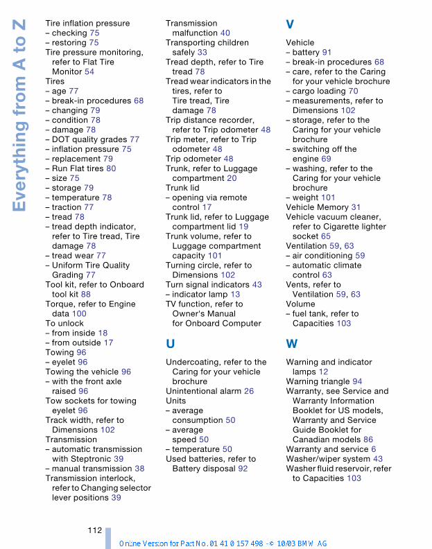
Eve
ryth
ing
fro
m A
to
Z
112
Tire inflation pressure– checking 75– restoring 75Tire pressure monitoring,
refer to Flat Tire Monitor 54
Tires– age 77– break-in procedures 68– changing 79– condition 78– damage 78– DOT quality grades 77– inflation pressure 75– replacement 79– Run Flat tires 80– size 75– storage 79– temperature 78– traction 77– tread 78– tread depth indicator,
refer to Tire tread, Tire damage 78
– tread wear 77– Uniform Tire Quality
Grading 77Tool kit, refer to Onboard
tool kit 88Torque, refer to Engine
data 100To unlock– from inside 18– from outside 17Towing 96– eyelet 96Towing the vehicle 96– with the front axle
raised 96Tow sockets for towing
eyelet 96Track width, refer to
Dimensions 102Transmission– automatic transmission
with Steptronic 39– manual transmission 38Transmission interlock,
refer to Changing selector lever positions 39
Transmission malfunction 40
Transporting children safely 33
Tread depth, refer to Tire tread 78
Tread wear indicators in the tires, refer to Tire tread, Tire damage 78
Trip distance recorder, refer to Trip odometer 48
Trip meter, refer to Trip odometer 48
Trip odometer 48Trunk, refer to Luggage
compartment 20Trunk lid– opening via remote
control 17Trunk lid, refer to Luggage
compartment lid 19Trunk volume, refer to
Luggage compartment capacity 101
Turning circle, refer to Dimensions 102
Turn signal indicators 43– indicator lamp 13TV function, refer to
Owner's Manual for Onboard Computer
UUndercoating, refer to the
Caring for your vehicle brochure
Unintentional alarm 26Units– average
consumption 50– average
speed 50– temperature 50Used batteries, refer to
Battery disposal 92
VVehicle– battery 91– break-in procedures 68– care, refer to the Caring
for your vehicle brochure– cargo loading 70– measurements, refer to
Dimensions 102– storage, refer to the
Caring for your vehicle brochure
– switching off the engine 69
– washing, refer to the Caring for your vehicle brochure
– weight 101Vehicle Memory 31Vehicle vacuum cleaner,
refer to Cigarette lighter socket 65
Ventilation 59, 63– air conditioning 59– automatic climate
control 63Vents, refer to
Ventilation 59, 63Volume– fuel tank, refer to
Capacities 103
WWarning and indicator
lamps 12Warning triangle 94Warranty, see Service and
Warranty Information Booklet for US models, Warranty and Service Guide Booklet for Canadian models 86
Warranty and service 6Washer/wiper system 43Washer fluid reservoir, refer
to Capacities 103
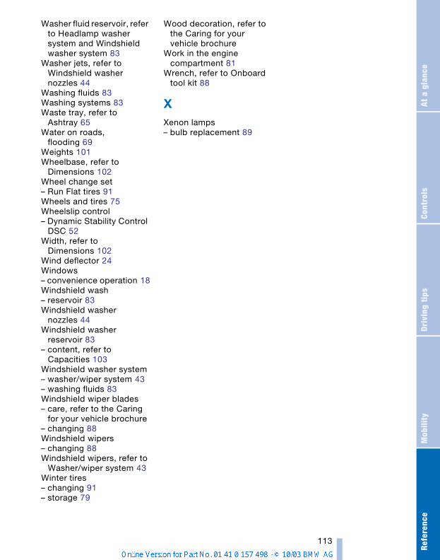
Refe
renc
eAt
a g
lanc
eCo
ntro
lsDr
ivin
g ti
psM
obili
ty
113
Washer fluid reservoir, refer to Headlamp washer system and Windshield washer system 83
Washer jets, refer to Windshield washer nozzles 44
Washing fluids 83Washing systems 83Waste tray, refer to
Ashtray 65Water on roads,
flooding 69Weights 101Wheelbase, refer to
Dimensions 102Wheel change set– Run Flat tires 91Wheels and tires 75Wheelslip control– Dynamic Stability Control
DSC 52Width, refer to
Dimensions 102Wind deflector 24Windows– convenience operation 18Windshield wash– reservoir 83Windshield washer
nozzles 44Windshield washer
reservoir 83– content, refer to
Capacities 103Windshield washer system– washer/wiper system 43– washing fluids 83Windshield wiper blades– care, refer to the Caring
for your vehicle brochure– changing 88Windshield wipers– changing 88Windshield wipers, refer to
Washer/wiper system 43Winter tires– changing 91– storage 79
Wood decoration, refer to the Caring for your vehicle brochure
Work in the engine compartment 81
Wrench, refer to Onboard tool kit 88
XXenon lamps– bulb replacement 89


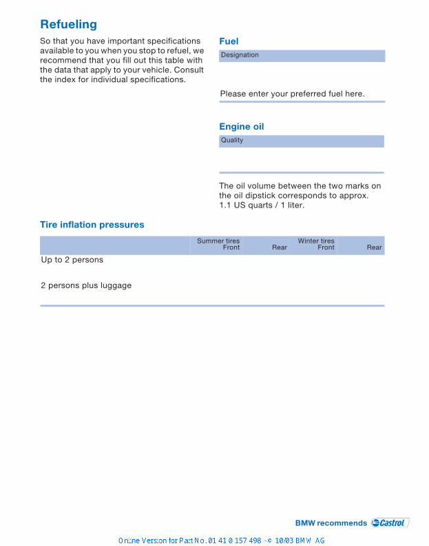
RefuelingSo that you have important specifications available to you when you stop to refuel, we recommend that you fill out this table with the data that apply to your vehicle. Consult the index for individual specifications.
Fuel
Engine oil
The oil volume between the two marks on the oil dipstick corresponds to approx. 1.1 US quarts / 1 liter.
Tire inflation pressures
Designation
Please enter your preferred fuel here.
Quality
Summer tiresFront Rear
Winter tiresFront Rear
Up to 2 persons
2 persons plus luggage

01
41
01
57
49
8 u
e
The UltimateDriving Machine
More about BMW
bmwusa.com