owner’s manual - hellenbrand · pdf fileowner’s manual. 2 electrical safety...
TRANSCRIPT

DO NOT REMOVE FROM UNITSee back cover for vital records
Owner’s Manual
2
ELECTRICAL SAFETYGROUNDINGThis product must be grounded. If it should malfunction or breakdown, grounding provides a path of leastresistance for electric current to reduce the risk of electrical shock. This system is equipped with a cordhaving an equipment-grounding conductor and a grounding plug. The plug must be plugged into anappropriate outlet that is properly installed and grounded in accordance with all local codes and ordinances.
DANGER – Improper connection of the equipment-grounding conductor can result in a risk of electrocution.Check with a qualified electrician or service personnel if you are in doubt as to whether the outlet is properlygrounded. Do not modify the plug provided with this system – if it will not fit the outlet, have a proper outletinstalled by a qualified electrician. Do not use any type of adapter with this system.
GROUND FAULT CIRCUIT INTERRUPTER PROTECTIONTo comply with the National Electrical Code (NFPA 70) and to provide additional protection from the risk ofelectric shock, this system should only be connected to a properly grounded, grounding-type power supplyreceptacle that is protected by a Ground Fault Circuit Interrupter (GFCI). Inspect operation of GFCI as permanufacturers suggested maintenance schedule.
EXTENSION CORDSIf an extension cord is necessary, use only 3-wire extension cords that have 3-prong grounding-type plugs and3-pole cord connectors that accept the plug from this system. Use only extension cords that are intended foroutdoor use. Use only extension cords having an electrical rating not less than the rating of the system. Acord rated for less amperes or watts than this system rating may overheat. Exercise caution when arrangingthe cord so that it will not be tripped over or pulled. Do not use damaged extension cords. Examine extensioncord before using and replace if damaged. Do not abuse extension cord. Keep extension cord away from heatand sharp edges. Always disconnect the extension cord from the receptacle before disconnecting this systemfrom the extension cord. Never yank cord to pull plug from outlet. Always grasp the plug and pull to disconnect.
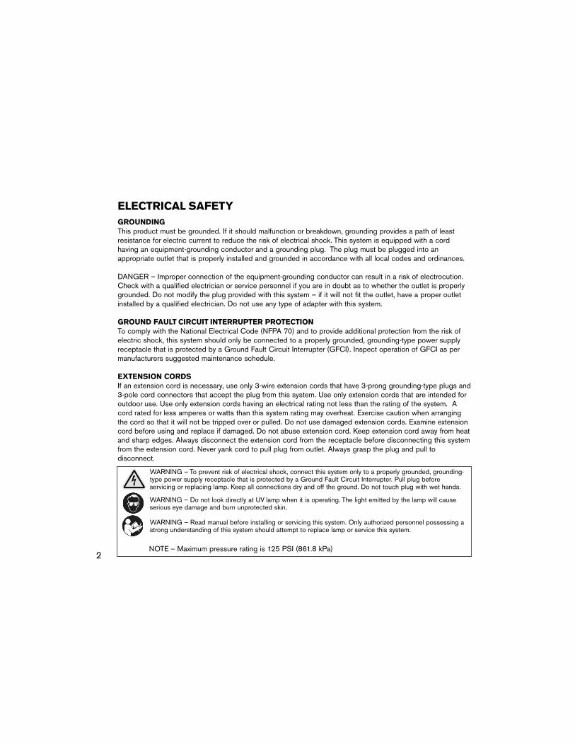
WARNING – To prevent risk of electrical shock, connect this system only to a properly grounded, grounding-type power supply receptacle that is protected by a Ground Fault Circuit Interrupter. Pull plug beforeservicing or replacing lamp. Keep all connections dry and off the ground. Do not touch plug with wet hands.
WARNING – Read manual before installing or servicing this system. Only authorized personnel possessing astrong understanding of this system should attempt to replace lamp or service this system.
WARNING – Do not look directly at UV lamp when it is operating. The light emitted by the lamp will causeserious eye damage and burn unprotected skin.
NOTE – Maximum pressure rating is 125 PSI (861.8 kPa)
3
WARNING – To guard against injury, basic safety precautionsshould be observed, including the following:1. READ AND FOLLOW ALL SAFETY INSTRUCTIONS.2. DANGER – To avoid possible electric shock, special care should be taken since water is employed in the
use of this system. Do not attempt repairs yourself. No user serviceable parts. Return the system to anauthorized service facility for service or discard the system.
3. Do not operate the system if it has a damaged cord or plug, or if it is malfunctioning or if it has beendropped or damaged in any manner.
4. Always unplug the system from an outlet before servicing or cleaning. Never yank cord to pull plug from outlet. Always grasp the plug and pull to disconnect.
5. Do not use the system for other than intended use. The use of attachments or accessories not recommendedor sold by Trojan Technologies may cause an unsafe condition and/or reduce disinfection performance.
6. CAUTION – To prevent risk of electrical shock, connect this system only to a properly grounded, grounding-type power supply receptacle that is protected by a Ground Fault Circuit Interrupter (GFCI). Inspect performance of GFCI as per manufacturer’s suggested maintenance schedule.
7. Visually inspect this system prior to installation. If the quartz sleeve or lamp is broken, cracked or damaged in any way, do not use. Contact Trojan Technologies Client Services for replacement parts.
8. WARNING – To reduce the risk of electrocution, keep all connections dry and off the ground. Do not touchplug with wet hands.
9. The light emitted by the lamp will cause serious eye damage and burn unprotected skin. Never look directlyat the lamp when it is operating. Do not plug unit into an electrical outlet without properly securing thelamp/sleeve into the reaction chamber. Disconnect lamp harness before removing lamp from reactor.
10. If the UV system malfunctions or fails, water must be boiled prior to consumption until the UV system isoperational and the water lines have been shocked. System failure is indicated by the system’s audiblealarm and absent (Models B & C) or red (all other models) indicator light.
11. Always shut off water flow and release water pressure before cleaning or maintaining unit.12. Intended for indoor use only. Power supply must not be exposed to weather elements. In seasonal
applications, reactor must be drained to prevent freezing.13. Installation of this system must be in accordance with local plumbing and electrical codes as well as any
and all applicable regulations and laws.14. SAVE THESE INSTRUCTIONS.

4

5
Components . . . . . . . . . . . . . . . . . . . . . . . . . . . . . . . .6Product Specifications . . . . . . . . . . . . . . . . . . . . . . . .8Part Numbers . . . . . . . . . . . . . . . . . . . . . . . . . . . . . . .8Water Quality Parameters . . . . . . . . . . . . . . . . . . . . .9Additional Water Treatment Equipment . . . . . . . . . . .9Installation . . . . . . . . . . . . . . . . . . . . . . . . . . . . . . . . . .10Operation . . . . . . . . . . . . . . . . . . . . . . . . . . . . . . . . . .12Service and Maintenance . . . . . . . . . . . . . . . . . . . . . .14Warranty . . . . . . . . . . . . . . . . . . . . . . . . . . . . . . . . . . .18Troubleshooting . . . . . . . . . . . . . . . . . . . . . . . . . . . . .20
Contents
By purchasing this system, you have taken the first step to providing safe drinkingwater for you and your family.
Designed using the most advanced UV technology available today, your UV systemwill operate with minimal maintenance and provide you with years of worry-freewater disinfection. All you have to do is follow the information in this manual,conduct the recommended maintenance, and replace the lamp once a year.
Thank you.

6
Models D, E, F, Pro7 & Pro15Model A
One power supply
Models B and C
Lamp CordUV Sensor Cord(optional)
Power Cord Lamp Cord
Push Button
Digital Display
Indicator Light
COMPONENTSEach TrojanUVMax system comes with the following components.
One power cordModels D, E, F,
Pro7 and Pro15 only
Reactor clamp(s)One on Models A, B, C, D,
two on larger models
One warranty cardOne owner’s manual
DO NOT REMOVE FROM UNITSee back cover for vital records
Owner’s Manual
External Control Relay

7
O-ring
Sleeve bolt
Lamp
Reactor
Sleeve
Sensor (if so equipped)
O-ring
One reactor; one lamp; one sleeve; one sleeve bolt; two O-rings; optional sensor.
Note: New systemscome with lamp, O-rings,sleeve bolt and sleeveassembled. Lamp andsleeve are separatereplacement parts.
Sensor port (if so equipped)

8
PART NUMBERS
A 650414 650415B 650411 650412C 650408 650409
602803 602730 602665002045602804 602731 602665002045602805 602732 602665002045
602826602827602828
Model Power Supply* SleeveBolt
QuartzSleeve
O-RingLamp254nm 185nm
120V 230V602799 602636 602637D
602636 602637E 602799 602636 602637F 602799
602636 602637Pro7 602799602636 602637Pro15 602799
UVSensor
602805 602732 602665002045 650505602806 602733 602665002045 650505602807
602828602829602830 602734 602665002045 650505
602806 602733 602665002045 650505602807
N/AN/A 602734 602665002045 650505
Model Lamp Cord**
Power Cord SleeveBolt
QuartzSleeve
O-RingLamp
254nm 185nm
Power Supply*
no sensor650405650402650398650510650512
650421650418650401
N/AN/A
120V 230V
w sensor no sensor w sensor120V 230V
650406650403650399650511650513
650422650419650416N/AN/A
* Includes power and lamp cords** Without sensor: 602799-120; with sensor: 602799-120S
PRODUCT SPECIFICATIONS
MODEL A B C D E F Pro7 Pro15Flow Rate 16 dose* 3 (11) 5 (19) 14 (53) 14 (53) 28 (106) 47 (178)GPM (LPM) 30 dose* 1 (3.8) 4 (15) 7 (26) 7 (26) 15 (56) 25 (94)
40 dose** 8.2 (31) 17.8 (67.4)Audible/Visual Lamp Failure Alarm � � � � � � � �
No-tools Maintenance � � � � � � � �
Safety Cap � � � � � � � �
Electronic Power Supply � � � � � � � �
Alarm Postpone — — — � � � � �
Elapsed Time Meter — — — � � � � �
Lamp-age Display & Alert — — — � � � � �
Digital Diagnostic Display — — — � � � � �
Electropolished Exterior — — — � � � � �
External Control Relay — — — � � � � �
UV Intensity Sensor — — — Optional Optional Optional � �
Solenoid (shut-off valve)*** — — — Optional Optional Optional Optional OptionalDynamic Flow Restrictor — — — Optional Optional Optional � �
Water Chamber Material 304 SST 304 SST 304 SST 304 SST 316 SST 316 SST 316 SST 316 SSTInlet/Outlet 3/8" FNPT 3/4" NPT 3/4" NPT 3/4" NPT 1" NPT 1" NPT 1" NPT 1" NPT
or BSP or BSP or BSP or BSP or BSP* See sizing charts for details. Flow rates shown are at 85% UVT. ** NSF Standard 55 Class A certifies flow rates shown. The temperature of the flowing water being treated must be between 10C and 350C (33.80F to 950F).*** Requires solenoid junction box.
9
These are recommended levels, for use as a guideline for pre-treatment requirements.
Iron: < .3 PPM (.3 mg/L)Hardness: < 120 PPM (7 Grains Per Gallon)% UVT: > 75%
ADDITIONAL WATER TREATMENT EQUIPMENTTo meet the water quality parameters described above, you may need to pre-treat your water to ensureappropriate disinfection. Pre-treatment equipment must be installed BEFORE the UV reactor. Ask your watertreatment dealer for further information about water quality and testing.
Pre-treatment systems can be comprised of one or more of the following elements:
• Carbon Filter• Iron Removal System• Water Softener• Cyst reduction filter (ANSI/NSF Standard 53 listed)
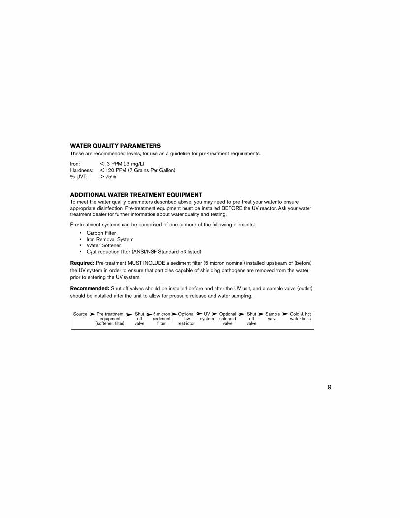
Required: Pre-treatment MUST INCLUDE a sediment filter (5 micron nominal) installed upstream of (before)the UV system in order to ensure that particles capable of shielding pathogens are removed from the waterprior to entering the UV system.
Recommended: Shut off valves should be installed before and after the UV unit, and a sample valve (outlet)should be installed after the unit to allow for pressure-release and water sampling.
WATER QUALITY PARAMETERS
Source Pre-treatment Shut 5-micron Optional UV Optional Shut Sample Cold & hotequipment off sediment flow system solenoid off valve water lines
(softener, filter) valve filter restrictor valve valve

* Mount by plugging into power source
Clearance for lampremoval, equal to
reactor length
4ft maximumPower source
Power supply*
Outlet
Inlet
UV reactor
MODEL A
10
INSTALLATIONFollow the instructions below inorder to avoid the risk of voidingyour warranty.
1. To protect your power supply, youmust use a UL1449 certifiedtransient voltage surge suppressorand a Ground Fault CircuitInterrupter (GFCI).
2. Determine location andorientation of reactor referring todiagrams on pages 10 and 11.
3. Attach reactor clamp(s) to thewall.
4. Insert reactor and tightenclamp(s).
5. Connect to plumbing.6. Mount power supply to wall,
referring to diagrams on pages10 and 11. Power supply shouldbe installed above all plumbing ifpossible
7. Insert power cord into malereceptacle on left side of powersupply (only on models D, E, F,Pro7 and Pro15).
8. Insert lamp/sleeve assembly (see Figure 9, page 16).
9. Attach the ground (green/yellow)and strain relief (red) wires fromthe lamp cord to the peg locatedon the reaction chamber, next tothe lamp port (outlet end).Secure both wires with locknutprovided.
REACTOR CHAMBER ORIENTATIONNote: Systemsequipped with asensor are notto be installedhorizontally.
Correct
Incorrect
10.Attach lamp cord to lamp (see Figures 10 and 11, page 17).
11.Plug system into the outlet.Note: When the UV system is firstplugged in, the alarm may soundtemporarily until the lamp is operational.
12.Clean the distribution lines:Once the UV system is installed, anycontamination in the distribution linesbetween the UV system and yourwater outlets must be removed.Similarly, if the power goes out andyour system is not equipped with anautomatic shut-off feature, you mustalso disinfect the downstreamdistribution lines.• Make sure the UV system is on.
Leave the system on during theentire cleaning process.
• Remove a filter housing and fill thefilter container with bleach (removethe filter for this process).
• Replace the filter housing and allowwater to flow to all faucets (hot andcold, inside and outside the house),your washing machine, toilets, andall other water outlets. Once youcan smell bleach in the hot and thecold water, turn the water to thatoutlet off. When this has beendone for all outlets, let the water sitin the water lines for two to fourhours.
• Completely flush all the lines aminimum of five minutes and thenput the filter back in the filterhousing.
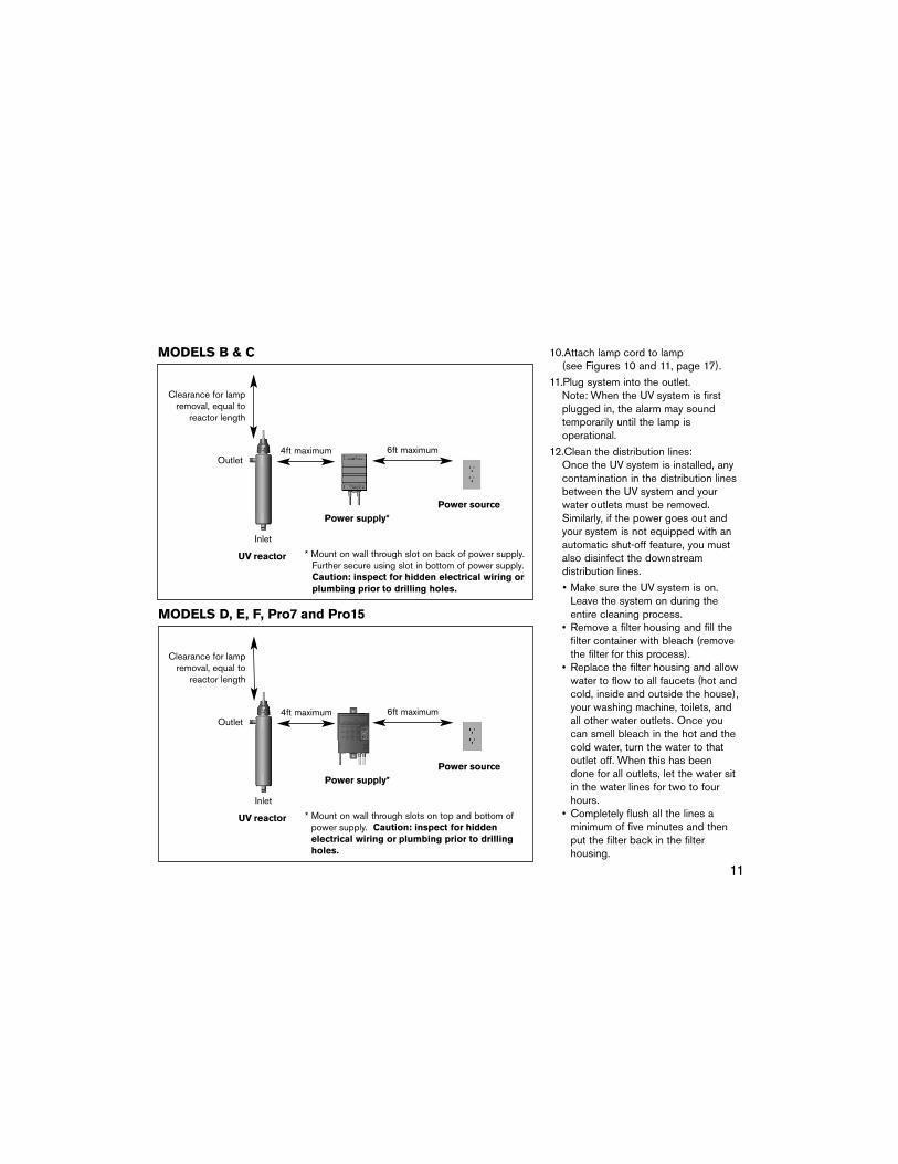
* Mount on wall through slot on back of power supply.Further secure using slot in bottom of power supply.Caution: inspect for hidden electrical wiring orplumbing prior to drilling holes.
Clearance for lampremoval, equal to
reactor length
4ft maximum 6ft maximum
Power sourcePower supply*
Outlet
Inlet
UV reactor
MODELS B & C
* Mount on wall through slots on top and bottom ofpower supply. Caution: inspect for hiddenelectrical wiring or plumbing prior to drillingholes.
Clearance for lampremoval, equal to
reactor length
4ft maximum 6ft maximum
Power sourcePower supply*
Outlet
Inlet
UV reactor
MODELS D, E, F, Pro7 and Pro15
11

12
OPERATION
Models A, B, and C
Power SupplyModel A is either 90-130V or 180-264V (50-60Hz). Models B & Care either 90-140V (60 Hz) or 190-265V (50Hz).
Indicator LightWhen the lamp is operatingproperly, the indicator light on thepower supply will be green. If thelamp is not operating properly, theindicator light will show red (ModelA) or will not light (Model B or C)and an audible alarm will sound.
The audible and visual alarmindicators will persist until eitherthe problem is corrected or thesystem is unplugged from theelectrical outlet. Note: If the systemis unplugged the water will not bedisinfected and the distributionlines will have to be cleaned.
If you experience any kind of alarm(audible or visual), see theTroubleshooting Section of this manual.
Models D, E, F, Pro7,and Pro15
Power SupplyAuto ranging, constant currentpower supply. Accepts 90-265Vat 50-60Hz.
Digital DisplayUnder normal operating conditionsthe Digital Display shows thenumber of months that the lamphas been operating. In the eventof a failure of any kind, the displaywill indicate the nature of theproblem. See the TroubleshootingSection for details.
Indicator LightDuring normal operation theindicator light will be green.
Indicator light will turn amber:• when lamp has operated for
11 months• if UV sensor (if so equipped)
detects a low UV output
Indicator light will turn red:• when lamp has operated for
12 months• if signal from UV sensor (if so
equipped) is below set point• if there is a failure of any kind,
such as a lamp malfunction
An audible alarm will sound when-ever the indicator light is red.
The audible and visual alarmindicators will persist until theproblem is corrected or thesystem is unplugged from theelectrical outlet. It is possible todisable the audible alarm; see 24-Hour Alarm Postpone Function.Note: If the system is unpluggedthe water will not be disinfectedand the distribution lines will haveto be cleaned.
If you experience any kind of alarm(audible or visual), see theTroubleshooting Section of thismanual.
Elapsed Time MeterThe Elapsed Time Meter measuresthe number of months that thelamp has been operating. Thelamp must be replaced after it hasbeen operating for 12 months.• After 11 months indicator light
turns amber.• After 12 months indicator light
turns red and alarm sounds.
Push buttonIndicator light
Digital display

13
Elapsed Time Meter Re-Set Function:After the lamp has beenchanged, the Elapsed TimeMeter must be reset by followingthe procedure below:
a) Disconnect the power supplyand leave it unplugged for 10seconds.
b) Press and HOLD the pushbutton.
c) Connect the power supply tothe outlet while continuing topress the push button. Theindicator light will flash greenfor about 3 seconds.
d) Continue to hold the pushbutton until the indicator lightflashes red, then releaseimmediately.
External Control RelayThis feature provides switchingfor the operation of a solenoid(shut-off) valve and/or remotealarm. When the lamp is notoperating properly or the UVsensor signals that the UVoutput is below set point, thecontacts will open causing thesolenoid to stop the water flowand/or a remote alarm to sound.The dry contact remains open ifthe lamp has been in operationfor 12 months or more.
UV SensorThe UV sensor measures theamount of UV light reaching it,allowing the system to monitorwhether the intensity is above theminimum required for properdisinfection. The sensor is factorycalibrated and is not fieldadjustable.
• After 14 months the alarm postponefunction is disabled, indicating thatthe lamp must be replaced and thatit is not providing properdisinfection.
• After lamp replacement, the timemeter must be reset (see ElapsedTime Meter Re-Set Function).
Push ButtonThe push button has two functions.
24-Hour Alarm Postpone Function:When the unit is in alarm, the indicatorlight is red and an alarm sounds. If youpress the push button for less thantwo seconds, the indicator light willflash red and the audible alarm willstop. The unit is still in alarm, but theaudio alarm stops for yourconvenience until you can contacta dealer.
This alarm will re-occur after 24 hoursif its cause has not been corrected.
If the unit detects another problemduring the 24-hour alarm postponeperiod, it will go into alarm again, theindicator light will turn solid red, andthe alarm will sound.
After 14 months of lamp operation,the alarm postpone will not work untilthe lamp is replaced and the timemeter is reset.
14
SERVICE AND MAINTENANCEThere are two regular maintenance requirements common to all UVsystems: cleaning and lamp replacement.
CLEANINGMinerals in the water will eventually coatthe quartz sleeve (which protects thelamp), as well as the sensor (if systemis so equipped). This coating must becleaned off periodically because itreduces the amount of UV light reachingthe water, thereby reducing disinfectionperformance.
Once a month, check the sleeve andclean it if you can see a mineral coatingstarting to form. If sleeve requires cleaning, refer to Lamp Replacementinstructions but re-install the originallamp. If system is equipped with a sensor, be sure to clean the sensoreach time the lamp is cleaned, as perLamp Replacement instructions.
LAMP REPLACEMENTThe lamp’s UV intensity decreases overtime. You can safely use your lamp for12 months, after which it must bereplaced. For instance, if you use yoursystem for 12 continuous months, youmust replace your lamp at the end ofthis period. If you use the system onlysix months each year, you would need
to change your lamp at the end of thesecond six-month period.
Follow the steps outlined below toreplace your lamp.
Lamp Removal1. Shut off water supply to (upstream
of) the UV system.
2. Open a tap downstream of the UVunit to release pressure, then closethis tap.
3. Unplug the power supply and let thelamp cool for 5 minutes.
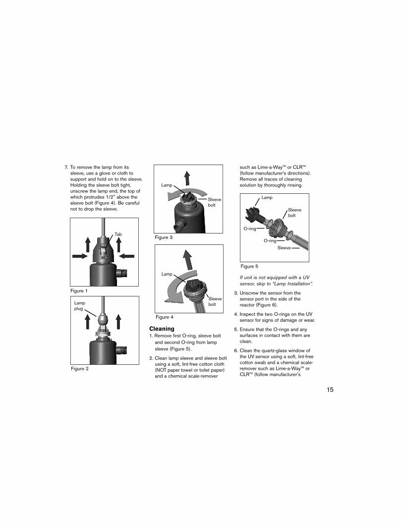
4. Squeeze the sides of the safety capin the area opposite the tabs (do notsqueeze tabs), and remove the cap(Figure 1).
5. Pull the lamp plug off the lamp end(Figure 2). Do not pull on the cordwhen removing the plug. Note:During lamp replacement, the groundand strain relief wires of the lampplug should remain connected to thepeg on the reactor.
6. Holding the sleeve bolt, unscrew thelamp/sleeve assembly and carefullyremove it from the reactor (Figure 3).Handle assembly by ends only. Ifrequired, a wrench can be placed onthe two flat sides of the sleeve bolt.Do NOT apply the wrench to thelamp end, which sits within thesleeve bolt and protrudes 1/2".
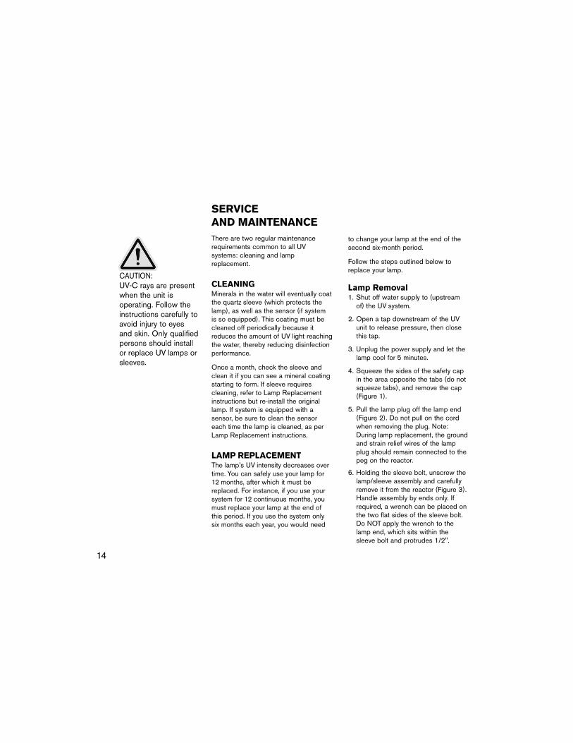
CAUTION:UV-C rays are presentwhen the unit is operating. Follow theinstructions carefully toavoid injury to eyesand skin. Only qualifiedpersons should installor replace UV lamps orsleeves.
15
7. To remove the lamp from itssleeve, use a glove or cloth tosupport and hold on to the sleeve.Holding the sleeve bolt tight,unscrew the lamp end, the top ofwhich protrudes 1/2" above thesleeve bolt (Figure 4). Be carefulnot to drop the sleeve.
Cleaning1. Remove first O-ring, sleeve bolt
and second O-ring from lampsleeve (Figure 5).
2. Clean lamp sleeve and sleeve boltusing a soft, lint-free cotton cloth(NOT paper towel or toilet paper)and a chemical scale-remover
such as Lime-a-WayTM or CLRTM
(follow manufacturer’s directions).Remove all traces of cleaningsolution by thoroughly rinsing.
If unit is not equipped with a UVsensor, skip to “Lamp Installation”.
3. Unscrew the sensor from the sensor port in the side of the reactor (Figure 6).
4. Inspect the two O-rings on the UVsensor for signs of damage or wear.
5. Ensure that the O-rings and anysurfaces in contact with them areclean.
6. Clean the quartz-glass window ofthe UV sensor using a soft, lint-freecotton swab and a chemical scale-remover such as Lime-a-WayTM orCLRTM (follow manufacturer’s
Figure 1
Tab
Figure 2
Lampplug
Figure 3
Lamp
Sleevebolt
Figure 4
Sleevebolt
Lamp
Figure 5
Lamp
O-ring
O-ring
Sleevebolt
Sleeve

Lamp
Lamp/sleeveassembly
16
directions). Remove all traces ofcleaning solution by thoroughlyrinsing.
7. Insert the UV sensor completelyinto the sensor port, turning thesensor slowly while doing so.Water may be put on the sensorO-ring to facilitate this procedure.
8. Screw the brass nut on finger tight.Caution: Over tightening maycause leakage.
Lamp Installation1. Each lamp and sleeve comes with
two new O-rings. Place the newO-rings and the original sleeve bolton the lamp sleeve as per Figure 7.Caution: Do not lubricate anyof the O-rings.
2. Put the lamp completely into thesleeve. Maintain it in that position
Figure 6
and screw the sleeve bolt into thelamp end until solidly hand-tight(Figure 8). Caution: Overtightening will break thequartz lamp sleeve.
3. Carefully place the lamp/ sleeveassembly into the reactor, makingsure it is centered. Apply pressureto the assembly and screw it intothe reactor until solidly hand-tight(Figure 9). Caution: Over tightening will break thequartz lamp sleeve.
4. Push the plug onto the end of thelamp while ensuring that the maletab on the lamp inserts into thefemale tab on the plug (Figure 10).
5. Push the safety cap on whileensuring that the grounding wiresare under the cap and not in theway of the tabs (Figure 11).
Figure 8
Sleevebolt
Sleeve
Figure 9
Figure 7
Lamp
O-ring
O-ring
Sleevebolt
Sleeve

2. Connect the power supply to theoutlet while continuing to pressthe push button. The indicator lightwill flash green for about 3seconds.
3. Continue to hold the push buttonuntil the indicator light flashes red,then release immediately.
4. Open the water line and check forleaks.
Disinfecting the Lines It is recommended that thedistribution lines be cleanedfollowing any maintenance procedurein which the water in the lines mayhave been exposed to the air or toany undisinfected water.
17
RestartingFor models A, B and C:1. Connect the power supply to the
outlet.
For all other models:1. Press and hold the push button
(Figure 12).
1. Remove a filter housing, removethe filter, and fill the housingcontainer with bleach. Replace thefilter housing.
2. Allow water to flow to all faucets(hot and cold, inside and outsideof the house), your washingmachine, toilets, and all otheroutlets. Once you can smellbleach in the hot and the coldwater, turn the water to that outletoff. When this has been done forall outlets, let the water sit in thewater lines for two to four hours.
3. Completely flush all the lines aminimum of five minutes and thenput the filter back in the filterhousing.
Figure 10
Lampplug
Figure 11
Push-button
Figure 12
18
WARRANTY
Our CommitmentTo maximize the superior quality of TrojanUV disinfection, each product must beproperly sized, installed, and maintained.If you experience difficulty with yourTrojan product, our Technical SupportCentre is available to help you.
During the applicable warranty periodnoted below, Trojan will provide warrantycoverage, described below, for yourproduct. After the product’s warrantyexpires, repairs and replacement partscan be provided to you for a reasonablecharge.
How to Get HelpTo obtain help under this warranty,contact the Trojan Technical SupportCenter at 1-800-265-5774 or by email [email protected]. Please haveavailable the model number, the date ofpurchase, the name of the dealer fromwhom you purchased your Trojanproduct (“the source dealer”), as well asa description of the problem you areexperiencing. A Trojan technician willhelp you troubleshoot the problem andisolate the defective part.
For more information, please refer to theTroubleshooting section of your Owner’sManual. Owner’s Manual information isalso available at www.trojanuv.com
To establish proof of purchase to make awarranty claim, you will need to eitherretain your original invoice or completeand return a warranty card, which willregister you as a product owner inTrojan’s database.
Specific Warranty CoverageWarranty coverage is specific to thefollowing Trojan products:
• TrojanUVMax™• Advantage Series• UV 700 Series• UV 600 Series
Ten-Year Limited Warrantyfor TrojanUVMax™ ReactionChamberTrojan warrants the reaction chamber onthe TrojanUVMax™ product to be freefrom defects in material and workmanshipfor a period of ten (10) years from thedate of purchase. During this time,Trojan will repair or replace, at itsoption, any defective TrojanUVMax™reaction chamber.
Please return the defective part to aTrojan dealer, who will return it to Trojan.Trojan will either make the necessaryrepairs or, if Trojan determines that areplacement is required, will provide areplacement part. Trojan will then returnthe part to the dealer. This warrantydoes not include shipping and handlingcharges which will be collected fromyou by the dealer.
Parts repaired or replaced under thisten (10) year warranty will be coveredunder warranty to the end of the originalten (10) year warranty period.
This warranty is also subject to theconditions and limitations outlinedunder the heading “General Conditionsand Limitations” below.
Five-Year Limited Warrantyfor Structural, Hardware andElectrical ComponentsTrojan warrants the structural, hardware,and electrical components to be free fromdefects in material and workmanship fora period of five (5) years from the dateof purchase. During this time, Trojan willrepair or replace, at its option, anydefective parts covered by the warranty.
Please return the defective part to aTrojan dealer, who will return it to Trojan.Trojan will either make the necessaryrepairs or, if Trojan determines that areplacement is required, will provide areplacement part. Trojan will then returnthe part to the dealer. This warrantydoes not include shipping and handlingcharges which will be collected fromyou by the dealer.
Parts repaired or replaced under thisfive (5) year warranty will be coveredunder warranty to the end of the originalfive (5) year warranty period.
This warranty is also subject to theconditions and limitations outlinedunder the heading “General Conditionsand Limitations” below.
One-Year Limited Warrantyfor Lamps, Sleeves and UVSensorsTrojan warrants lamps, sleeves and UV sensors to be free from defects in material and workmanship for a periodof one (1) year from the date of purchase.During this time, Trojan will repair or
19
replace, at its option, any defectiveparts covered by the warranty.
The warranty period for lamps andsleeves may be verified using datecodes in addition to purchase receiptsand Trojan’s database of registeredowners. Trojan will advise you whetherthe defective item needs to be returnedto a Trojan dealer for failure analysis.Replacement lamps and sleevesprovided under warranty will be sent toyour Trojan dealer.
If the UV sensor experiences a problemwhich Trojan confirms is covered bywarranty, please return the sensor to aTrojan dealer who will return it to Trojan.Trojan will either repair or replace thesensor and return the sensor to yourdealer.
This warranty on lamps, sleeves andsensors does not include shipping and handling charges which will be collected from you by the dealer.
Parts replaced under this one (1) yearwarranty will be covered under warrantyto the end of the original one (1) yearwarranty period.
This warranty is also subject to theconditions and limitations outlinedunder the heading “General Conditionsand Limitations” below.
Warranty for ReplacementLamps and PartsTrojan warrants replacement lamps, purchased for annual routine maintenance, and other parts purchasedto repair product components that are
no longer covered by the original warranty, to be free from defects inmaterial and workmanship for a periodof three (3) months from the date ofpurchase. During this time, Trojan will repair or replace, at its option, a defective replacement lamp or part free of charge except for shipping and handling charges.
The warranty period on replacementlamps and parts will be verified usingdate codes and/or purchase receipts.Trojan will advise you whether thedefective item needs to be returned to a Trojan dealer for failure analysis.Replacement lamps and parts providedunder warranty will be sent to yourTrojan dealer.
General Conditions andLimitationsNone of the above warranties coverdamage caused by improper use ormaintenance, accidents, acts of God orminor scratches or imperfections thatdo not materially impair the operation ofthe product. The warranties also do notcover products that are not installed asoutlined in the applicable Owner’sManual.
The limited warranties described aboveare the only warranties applicable to theTrojan products listed in the “SpecificWarranty Coverage” section. Theselimited warranties outline the exclusiveremedy for all claims based on a failureof or defect in any of these products,whether the claim is based on contract,tort (including negligence), strict liabilityor otherwise. These warranties are in
lieu of all other warranties whetherwritten, oral, implied or statutory.Without limitation, no warranty ofmerchantability or of fitness for aparticular purpose shall apply to any of these products.
Trojan does not assume any liability for personal injury or property damagecaused by the use or misuse of any ofthe above products. Trojan shall not in any event be liable for special, incidental, indirect or consequentialdamages. Trojan's liability shall, in all instances, be limited to repair orreplacement of the defective product or part and this liability will terminateupon expiration of the applicable warranty period.

20
SITUATION POSSIBLE CAUSE POSSIBLE SOLUTIONBreaker repeatedly trips Connection between lamp and lamp
cord is wetClean and dry the cord and lamp, checkunit for leaks
Short circuit in the electrical assembly
Replace power supply
Leak at inlet or outlet Threaded pipe fittings are leaking Clean threads, reseal with Teflon tape,and re-tighten
Leak detected from area of reactor
Condensation of moist air on cold reactor (slow accumulation)
Control humidity, relocate unit, or insulatereactor
O-ring on sleeve bolt damaged, deteriorated, or incorrectly installed
Inspect and replace if deteriorated
Lamp/sleeve assembly not properly installed (too tight or not tight enough)
Tighten assembly solidly hand-tight
Audible alarm Power failure, lamp failure Unplug for 2 minutes then restart
Replace lamp
Replace power supply
TroubleshootingModels A, B, C

21
TroubleshootingModels D, E, F, Pro 7 and Pro 15 SITUATION POSSIBLE CAUSE POSSIBLE SOLUTION
Digital display does not read anything
Unit is unpluggedNo power at AC power outlet
Power cord is damagedPower surge caused damage toelectrical assembly
Plug unit into AC power outlet
Replace fuse or reset breakerReplace power cord
Replace power supply and use a surge protector
Breaker repeatedly trips Connection between lamp and lampcord is wet
Clean and dry the cord and lamp, checkunit for leaks
Short circuit in the electrical assembly
Replace power supply
Leak at inlet or outlet Threaded pipe fittings are leaking Clean threads, reseal with Teflon tape,and re-tighten
Leak detected from area of reactor
Condensation of moist air on cold reactor (slow accumulation)
Control humidity, relocate unit, or insulatereactor
O-ring on sleeve bolt damaged, deteriorated, or incorrectly installed
Inspect and replace if deteriorated
Lamp/sleeve assembly not properly installed (too tight or not tight enough)
Tighten assembly solidly hand-tight
Digital Display indicates L0, L1, L2, or L3
Lamp is not operating Inspect lamp cord and reconnect; ensure safety cap snaps into place
Digital Display reads F0 or F1 Restart; if this fails, replace power supply
Digital Display reads C0 Restart; if this fails, replace power supply
Power supply failure
Indicator light is malfunctioning
Digital Display indicates a number between 0 and 10
Not an alarm condition
Digital Display indicates 11 Not an alarm condition; lamp is in its 12th month of operation and will require replacement shortly
Ensure that you have a replacement lamp on hand
Digital Display indicates 12, 13 or 14
Lamp has reached the end of its life Replace lamp and reset elapsed time meter
Note: If push-button is pressed during an alarm condition, the audible alarm is postponed 24 hours. The alarm condition persists.
Replace lamp and reset elapsed time meter
22
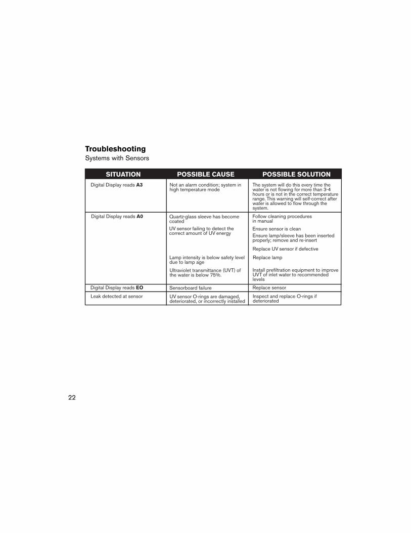
TroubleshootingSystems with Sensors

23
NSF information pertains to TrojanUVMax™ Pro7 and Pro15 models
This Class A system conforms to NSF Standard 55 for the disinfection of microbiologically contaminated waterthat meets all other public health standards. The system is not intended for treatment of water that has an obviouscontamination source, such as raw sewage; nor is the system intended to convert wastewater to microbiologicallysafe drinking water. The system is intended to be installed on visually clear water (not coloured, cloudy, or turbidwater). If this system is used for the treatment of surface waters a prefilter found to be in compliance for cystreduction under ANSI/NSF Standard 53: Drinking Water Treatment Units - Health Effects shall be installedupstream of the system.
NSF Standard 55 defines waste water to include human and/or animal body waste, toilet paper, and any othermaterial intended to be deposited in a receptacle designed to receive urine and/or feces (black waste); and otherwaste materials deposited in plumbing fixtures (gray waste).
System tested and certifiedby NSF Internationalagainst ANSI/NSF
Standard 55 for disinfection performance, Class A.

A B C D E Pro7 F Pro15
Head Office 3020 Gore Road, London, Ontario, Canada N5V 4T7Tel: (519) 457-3400 Fax: (519) 457-3030 www.trojanuv.com
Pri
nte
d i
n C
anad
a.C
opyr
ight
©20
01Tr
ojan
Tec
hnol
ogie
s In
c. L
ondo
n, O
ntar
io, C
anad
a.N
o pa
rt o
f th
is m
anua
l may
be
repr
oduc
ed, s
tore
d in
a r
etrie
val s
yste
m, o
rtra
nsm
itted
in
any
form
orb
y an
y m
eans
with
out t
he w
ritte
n pe
rmis
sion
of T
roja
n Te
chno
logi
es In
c.
6026
69 R
ev D
Installed by: ____________________________________________________________________
Date of installation: ____________________________________________________________________
Service numbers:Installer - call _____________________________________________________________________
Trojan - call (519) 457-3400
Serial number: ____________________________________________________________________(see decal on back of power supply)
Lamps must be replaced after 12 months of operation to ensure properdisinfection of your water.
Clean quartz sleeve and UV sensor (if equipped) frequently for optimum performance.
1st: _____________________________ 6th: _____________________________
2nd: _____________________________ 7th: _____________________________
3rd: _____________________________ 8th: _____________________________
4th: _____________________________ 9th: _____________________________
5th: _____________________________ 10th: _____________________________
Model installed (check):
Lamp replacement dates:
602803 602804 602805 602806 602807Corresponding lamp: