owner’s manual - hot tubs, swim spas and … not dive. 1 master spas owner’s manual welcome to...
TRANSCRIPT

O W N E R ’ S M A N U A L


1DO NOT DIVE. 1DO NOT DIVE.
MASTER SPAS OWNER’S MANUAL
Welcome To Ultimate Relaxation!Thank you for choosing your new spa built by Master Spas. Please read the entire Owner’s Manual before installing and using your spa. The goal of this manual is to provide you with safety and operational information plus some tips that will help you enjoy your spa to its fullest.
At the time of print, this manual is accurate in its information. Master Spas reserves the right to change or improve its product without prior notice. To check on updates or for other informa-tion, please visit www.masterspas.com and follow the links to the customer support section.
Record Of Ownership
Name ��������������������������������������������������������������������������������
Address ������������������������������������������������������������������������������
City ��������������������������������������������������������� State ������ Zip ���������
Phone # (������)��������-���������� Date Purchased ������ /������ /�������
Model ��������������������������������� Serial # ���������������������������������������
Dealer Name �������������������������������������������������������������������������
Service Tech Rep ����������������������������������������������������������������������
Serial Number LocationThe serial number for your spa is located near the filter area, on the spa system pack, or on the listing plate on the skirting. It is a seven digit number. Ex. 1512345
Register Your SpaPlease be sure to register your spa so we can efficiently assist with any questions you may have. Until your spa has been registered, Master Spas Inc. will not have record of your ownership.
To register your spa, visit www.MasterSpas.com and access our “Customer Support” link on the page. This area will offer online registration capability along with other support information.
6927 Lincoln Parkway Fort Wayne, Indiana 46804
www.masterspas.com
2DO NOT DIVE. 2
TABLE OF CONTENTS
Record of Ownership .............................................................................................................. 1
Table of Contents ................................................................................................................... 2
Safety Instructions ............................................................................................................ 3-10
Glossary of Spa Terminology ........................................................................................... 11-13
Site Preparation / General Guidelines .............................................................................. 14-15
Installation Instructions ................................................................................................... 16-17
The Advantages of Eco Pur Filtration .................................................................................... 18
Water Chemistry Terms You Should Know ....................................................................... 19-20
Why Are Chemicals Important in a Spa ................................................................................ 21
Water Maintenance ......................................................................................................... 22-25
Start-Up ........................................................................................................................ 22
Schedule .................................................................................................................. 23-24
Troubleshooting Guide .................................................................................................. 25
Regular Maintenance Procedures ..................................................................................... 26-30
Spa Troubleshooting Guide ............................................................................................. 31-32
Winterizing & Storing Your Spa ............................................................................................ 33
Spa Care & Maintenance Record ...................................................................................... 34-35
Electrical Requirements ................................................................................................... 36-37
Model Specifications ............................................................................................................ 38
Spa Controls ................................................................................................................... 39-56
Wi-Fi Module (if equipped) ................................................................................................... 57
Deluxe Fusion Air Stereo Option (if equipped) ................................................................. 58-60
Deluxe Fusion BT Stereo Option (if equipped) .................................................................. 61-69
Mast3rPur (if equipped) .................................................................................................. 70-72

3DO NOT DIVE. 100DO NOT DIVE.
SAFETY INSTRUCTIONS
SAVE THESE INSTRUCTIONS Included with your new spa is a safety sign. The sign is for you and your guest’s protection
and is suitable for outdoor use in wet locations. The sign should be placed in a location visible to all users of the spa.
Please take time to point out the physical location of the safety sign and the importance of the safety precautions displayed on the safety sign to all of your guests. Remember, your safety and the safety of anyone who enjoys the use of your spa is our utmost concern.
The sign should be mounted with screws or another type of permanent fastener. Additional or replacement signs can be obtained from your dealer or direct from the factory.
INTRODUCTIONIt’s time to relax! You now have your very own portable spa by Master Spas, Inc. By fully under-standing the operation of each of the features of your new Master Spa, you will be assured of many years of hassle-free, hot water therapy and fun.
Your safety is of paramount importance to the MasterSpas family. We urge you to read and become thoroughly familiar with all safety aspects addressed in this manual.
Through reading and totally understanding the important information in your owner’s manual, you will realize that you now own THE ULTIMATE RELAXATION MACHINE!
4DO NOT DIVE. 101DO NOT DIVE.
SAFETY INSTRUCTIONS
IMPORTANT SAFETY INSTRUCTIONSWhen installing and using this electrical equipment, basic safety precautions should be observed including the following:
READ AND FOLLOW ALL INSTRUCTIONSWARNING – To reduce the risk of injury, do not permit children to use this product unless they are closely supervised at all times.
A wire conductor is provided on this unit to connect a minimum 6 AWG (13.302mm2) solid copper conductor between this unit and any metal equipment, metal enclosures of electrical equipment, metal water pipe, or conduit within 5 feet (1.5m) of the unit
(For cord-connected/convertible units) DANGER – Risk of injury. a) Replace damaged cord immediately. b) Do not bury cord. c) Connect to a grounded, grounding type receptacle only.
(For units intended for indoor use only) WARNING – For indoor use only. This unit is not intended for outdoor use.
(For units intended for outdoor use only) WARNING – For outdoor use only. This unit is not intended for indoor use.

5DO NOT DIVE. 102DO NOT DIVE.
SAFETY INSTRUCTIONS
IMPORTANT SAFETY INSTRUCTIONS (CONT.)(For units with GFCI) WARNING – This product is provided with a ground-fault circuit interrupter
located on the front panel of selected swim spas and on the power cord of 120 volt convertible spas. The GFCI must be tested before each use. With the product operating, open the service door. When the product stops operating, this merely indicates that the door is equipped with an electrical interlock. Next, push the test button on the GFCI and close the service door. The prod-uct should not operate. Now open the service door, push the reset button on the GFCI and close the service door. The product should now operate normally. When the product fails to operate in this manner, there is a ground current flowing indicating the possibility of an electric shock. Disconnect the power until the fault has been identified and corrected.
DANGER – Risk of Accidental Drowning. Extreme caution must be exercised to pre-vent unauthorized access by children. To avoid accidents, ensure that children can-not use this spa unless they are supervised at all times.
DANGER – Risk of Injury. The suction fittings in this spa are sized to match the spe-cific water flow created by the pump. Should the need arise to replace the suction fittings or the pump, be sure that the flow rates are compatible.
Never operate spa if the suction fittings are broken or missing. Never replace a suc-tion fitting with one rated less than the flow rate marked on the original suction fitting.
DANGER – Risk of Electric Shock. Install at least 5 feet (1.5m) from all metal sur-faces. As an alternative, a spa may be installed within 5 feet of metal surfaces if each metal surface is permanently connected by a minimum 8AWG (8.4mm2) solid copper conductor to the wire connector on the terminal box that is provided for this purpose.
DANGER – Risk of Electric Shock. Do not permit any electric appliance, such as a light, telephone, radio, or television, within 5 feet (1.5 m) of a spa.
WARNING – To reduce the risk of injury:
a) The water in a spa should never exceed 40˚C (104˚F). Water temperatures between 38˚C (100˚F) and 40˚C are considered safe for a healthy adult. Lower water temperatures are recommended for young children and when spa use exceeds 10 minutes.
6DO NOT DIVE. 103DO NOT DIVE.
SAFETY INSTRUCTIONS
IMPORTANT SAFETY INSTRUCTIONS (CONT.) b) Since excessive water temperatures have a high potential for causing fetal
damage during the early months of pregnancy, pregnant or possibly preg-nant women should limit spa water temperatures to 38˚C (100˚F).
c) Before entering a spa, the user should measure the water temperature since the tolerance of water temperature- regulating devices varies.
d) The use of alcohol, drugs, or medication before or during spa use may lead to unconsciousness with the possibility of drowning.
e) Obese persons and persons with a history of heart disease, low or high blood pressure, circulatory system problems, or diabetes should consult a physician before using a spa.
f) Persons using medication should consult a physician before using a spa since some medication may induce drowsiness while other medication may affect heart rate, blood pressure, and circulation.
(For spas with a gas heater)
WARNING – Risk of Suffocation. This spa is equipped with a gas heater and is intended for outdoor use only unless proper ventilation can be provided for an indoor installation.
HYPERTHERMIA
Hyperthermia occurs when the internal temperature of the body reaches a level several degrees above the normal body temperature of 98.6° F.
THE SYMPTOMS OF HYPERTHERMIA INCLUDE:
• Dizziness • Fainting • Drowsiness • Lethargy • Increase in Internal Body Temperature
THE EFFECTS OF HYPERTHERMIA INCLUDE:
Unawareness of Impending Hazard • Failure to Perceive Heat • Failure to Recognize the Need to Exit Spa • Physical Inability to Exit Spa • Fetal Damage in Pregnant Women • Unconsciousness Resulting in a Danger of Drowning
7DO NOT DIVE. 104DO NOT DIVE.
SAFETY INSTRUCTIONS
IMPORTANT SAFETY INSTRUCTIONS (CONT.)DANGER – To reduce the risk of injury to persons, do not remove the suction grate. Suction through drains and skimmers is powerful when the jets in the spa are in use. Damaged covers can be hazardous to small children and adults with long hair. Should any part of the body be drawn into these fittings, turn off the spa immediately. As a precaution, long hair should not be allowed to float in the spa.
WARNING – Install the spa so that water can be easily drained out of the compart-ment containing electrical components so as not to damage equipment. When installing the spa make sure to allow for an adequate drainage system to deal with any overflow water. Please allow for at least 3 feet of clearance around the perim-eter of the spa to provide enough room to access for servicing. Contact your local dealer for their specific requirements.
WARNING – The spa should be covered with an approved locking cover when not in use, to prevent unauthorized entry and injuries.
WARNING – People with infections, sores or the like should not use the spa. Warm and hot water temperatures may allow the growth of infectious bacteria if not properly disinfected.
CAUTION – Safe temperatures for swimming or aquatic exercise is around 80˚F.
CAUTION – Risk of Electrical Shock. Do not leave audio compartment open. Audio CD controls are not to be operated while inside the spa.
CAUTION – Replace components only with identical components.
WARNING – Risk of Electric Shock. Do not connect any auxiliary components (for example, additional speakers, headphones, additional audio/ video components etc.) to the system. These units are not provided with an outdoor antenna.
Do not service this product yourself as opening or removing covers may expose you to dangerous voltage or other hazards. Refer all servicing to qualified service personnel.
If the power supply cord(s) are damaged, water is entering the speaker, audio compartment, or any other component in the electrical equipment compartment area, the protective shield is showing signs of deterioration, or there are signs of other potentially hazardous damage to the unit, turn off the circuit breaker from the wall and refer servicing to qualified personnel.

8DO NOT DIVE. 105DO NOT DIVE.
SAFETY INSTRUCTIONS
IMPORTANT SAFETY INSTRUCTIONS (CONT.) The unit should be subjected to periodic routine maintenance once every quarter to make sure that the it is operating properly.
DANGER – Risk of Electric Shock. A green colored terminal or a terminal marked G, GR, Ground, Grounding or the symbol shown in Figure 14.1 of UL 1563 is located inside the supply terminal box or compartment. To reduce the risk of electric shock, this terminal must be connected to the grounding means provided in the electric supply service panel with a continuous copper wire equivalent in size to the circuit conductors supplying this equipment.
At least two lugs marked “Bonding Lugs” are provided on the external surface or on the inside of the supply terminal box or compartment. To reduce the risk of electric shock, connect the local common bonding grid in the area of the spa to these terminals with an insulated or bare copper conductor not smaller than 8AWG.
All field installed metal components such as rails, ladders, drains, or other similar hardware within 3m of the spa shall be bonded to the equipment grounding bus with copper conductors not smaller than 8AWG.
SAVE THESE INSTRUCTIONS

9DO NOT DIVE. 106DO NOT DIVE.
SAFETY INSTRUCTIONS
WARNING: CHILDREN SHOULD NOT USE SPAS OR HOT TUBS WITHOUT ADULT SUPERVI-SION
AVERTISSEMENT: NE PAS LAISSER LES ENFANTS UTILISER UNE CUVE DE RELAXATION SANS SURVEILLANCE
WARNING: DO NOT USE SPAS OR HOT TUBS UNLESS ALL SUCTION GUARDS ARE INSTALLED TO PREVENT BODY AND HAIR ENTRAPMENT.
AVERTISSEMENT: POUR ÉVITER QUE LES CHEVEUX OU UNE PARTIE DU CORPS PUISSENT ÊTRE ASPIRES, NE PAS UTILISER UNE CUVE DE RELAXATION SI LES GRILLES DI PRISE D’ASPIRATION NE SONT PAS TOUTES EN PLACE
WARNING: PEOPLE USING MEDICATIONS AND/OR HAVING AN ADVERSE MEDICAL HIS-TORY SHOULD CONSULT A PHYSICIAN BEFORE USING A SPA OR HOT TUB.
AVERTISSEMENT: LES PERSONNES QUI PRENNENT DES MÉDICAMENTS OU ONT DES PROBLÉMES DE SANTÉ DEVRAIENT CONSULTER UN MÉDECIN AVANT D’UTILISER UNE CUVE DE RELAXATION
WARNING: PEOPLE WITH INFECTIOUS DISEASES SHOULD NOT USE A SPA OR HOT TUB
AVERTISSEMENT: LES PERSONNES ATTEINTES DE MALADIES INFECTIEUSES NE DEVRAIENT PAS UTILISER UNE CUVE DE RELAXATION
WARNING: TO AVOID INJURY EXERCISE CARE WHEN ENTERING OR EXITING THE SPA OR HOT TUB.
AVERTISSEMENT: POUR ÉVITER DES BLESSURES, USER DE PRUDENCE EN ENTRANT DANS UNE CUVE DE RELAXATION ET EN SORTANT
WARNING: DO NOT USE DRUGS OR ALCOHOL BEFORE OR DURING THE USE OF A SPA OR HOT TUB TO AVOID UNCONSCIOUSNESS AND POSSIBLE DROWNING
AVERTISSEMENT: POUR ÉVITER L’ÉVANOUISSEMENT ET LA NOYADE ÉVENTUELLE, NE PRENDE NI DROGUE NI ALCOOL AVANT D’UTILISER UNE CUVE DE RELAXATION NI QUAND ON S’Y TROUVE
WARNING: PREGNANT OR POSSIBLY PREGNANT WOMEN SHOULD CONSULT A PHYSI-CIAN BEFORE USING A SPA OR HOT TUB.
AVERTISSEMENT: LES FEMMES ENCEINTES, QUE LEUR GROSSESSE SOIT CONFIRMÉE OU NON, DEVRAIENT CONSULTER UN MÉDECIN AVANT D’UTILISER UNE CUVE DE RELAXATION
WARNING: WATER TEMPERATURE IN EXCESS OF 38˚C MAY BE INJURIOUS TO YOUR HEALTH
AVERTISSEMENT: IL PEUT ÊTRE DANGEREUX POUR LA SANTÉ DE SE PLONGER DANS DE L’EAU A PLUS DE 38˚C
WARNING: BEFORE ENTERING THE SPA OR HOT TUB MEASURE THE WATER TEMPERA-TURE WITH AN ACCURATE THERMOMETER
AVERTISSEMENT: AVANT D’UTILISER UNE CUVE DE RELAXATION MESURER LA TEMPÉRATURE DE L’EAU À L’AIDE D’UN THERMOMÉTRE PRÉCIS

10DO NOT DIVE. 107DO NOT DIVE.
SAFETY INSTRUCTIONS
WARNING: DO NOT USE A SPA OR HOT TUB IMMEDIATELY FOLLOWING STRENUOUS EXERCISE
AVERTISSEMENT: NE PAS UTILISER UNE CUVE DE RELAXATION IMMÉDIATEMENT APRÉS UN EXERCISE FATIGANT
WARNING: PROLONGED IMMERSION IN A SPA OR HOT TUB MAY BE INJUROUS TO YOUR HEALTH
AVERTISSEMENT: L’UTILISATION PROLONGÉE D’UNE CUVE DE RELAXATION PEUT ÊTRE DANGEREUSE POUR LA SANTÉ
WARNING: DO NOT PERMIT ELECTRIC APPLIANCES (SUCH AS LIGHT, TELEPHONE, RADIO, OR TELEVISION) WITHIN 1.5 M OF THIS SPA OR HOT TUB
AVERTISSEMENT: NE PAS PLACER D’APPAREIL ÉLECTRIQUE (LUMINAIRE, TÉLÉPHONE, RADIO, TÉLÉVISEUR, ETC) À MOINS DE 1.5 M DE CETTE CUVE DE RELAXATION
CAUTION: MAINTAIN WATER CHEMISTRY IN ACCORDANCE WITH MANUFACTURER’S INSTRUCTION
ATTENTION: LA TENEUR DE L’EAU EN MATIÉRES DISSOUTES DOIT ÊTRE CONFORME AUX DIRECTIVES DU FABRICANT
Hyperthermia occurs when the internal temperature of the body reaches a level several degrees above the normal body temperature of 37˚C. The symtoms of hyperthermia include drowsiness, lethargy, and an increase in the internal temperature of the body. The effects of hyperthermia include (a) unawareness of impending hazard; (b) failure to perceive heat; (c) failure to recognize the need to exit spa; (d) physical inability to exit spa; (e) fetal damage in pregnant women; and (f) unconsciousness and danger of drowning.
WARNING: THE USE OF ALCOHOL OR DRUGS CAN GREATLY INCREASE THE RISK OF FATAL HYPERTHERMIA IN HOT TUBS AND SPAS
LA CONSOMMATION D’ALCOOL OU DE DROGUE AUGMENTE CONSIDÉRABLEMENT LES RISQUES D’HYPERTHERMIE MORTELLE DANS UNE CUVE DE RELAXATION.

11DO NOT DIVE. 100DO NOT DIVE.
GLOSSARY OF SPA TERMINOLOGY
Your new Master Spa features a variety of jets. All jets, regardless of style return the water to the spa. Air is mixed with the water by using the air controls (if equipped) creating a gentle to most vigorous massage. Water flow is adjusted by simply turning the outer face of the jet. Your Master Spa may have a combination of pulsating, rotating, dual pulsating and directional adjustable jets.
1. THERAPY JETS Located throughout the seats of the spa to offer a variety of therapy combinations.
2. NECK JETS (if equipped)
Located above the normal water level to provide massaging action to the back of the neck.
3. SHOULDER JETS (if equipped)
Located above the normal water level to provide massaging action to the shoulders.
4. MASTER BLASTER FOOT THERAPY JET (if equipped) Large jet with several fixed nozzles located in the bottom of the spa near the floor to provide
excellent massage to the feet.
5. JET DIVERTER VALVE (if equipped) Located on the top flange of the spa, this large valve physically diverts the flow of water from one group of jets to another. Be sure that no sand or particles are brought into the spa as they will cause the diverter to seize up. It is best to turn the diverter valve only when the pump is turned off.
6. WATER FEATURE VALVE (if equipped) Located on the top flange of the spa, this smaller valve adjusts water flow to the waterfalls and/or water features in your spa.
NOTE: When the spa is not in use, this valve should be turned mostly shut (not completely shut) to prevent the water features from allowing water to hit the cover while it is closed. If left mostly open, water may hit the cover and possibly run out of the spa causing water loss.
7. AIR CONTROL VALVE These smaller valves are located around the top of your spa. You may increase or decrease the force of your jets by opening or closing the air control valves. Each air control valve will typi-cally function 1 to 2 groups or seats of jets in the spa. When not in use the air controls should be kept in the closed position as the air being introduced in to the water can tend to cool the water and increase the dissipation rate of sanitizer levels.
8. TOPSIDE CONTROL PANEL You may safely control spa functions from inside or outside your spa using the Topside Control Panel. This Panel is used to control the water temperature, pumps, the spa light, automatic filtration cycles and other advanced functions. The digital display will give you a constant tem-perature readout and will notify you in case of certain malfunctions. Several user programmable functions are also available.
12DO NOT DIVE. 101DO NOT DIVE.
GLOSSARY OF SPA TERMINOLOGY
9. PERSONAL REMOTE CONTROL (if equipped)
Select spa models may have an additional remote which allows the user to control the jet therapy while remaining in the seat (if applicable). By pressing the control one time, you will activate the pump. Press again for high speed and again to turn it off.
10. EQUIPMENT ACCESS PANEL This is the skirt panel located below the Topside Control Panel. This area houses the major-
ity of components responsible for the spas operation. These components include the pumps, heater, spa control system, ozonator (if equipped), and LED light system (if equipped). Pump and equipment placement may vary by model.
11. ACCESS PANELS These are the skirt panels located around all four sides of the spa. All of the skirt panels are
removable should service be required. Master Spas recommends at least 3 feet of access be provided around the spa.
12. FILTER LID This lid fits over the filter area and weir gate to cover the filters. Remove filter lid to access
filters for maintenance.
14. WEIR GATE The weir gate is the horizontal door located in front of the filters that helps keep debris
trapped in the filter area
15. SPA CONTROL SYSTEM This houses the wiring and electrical components necessary to operate the spa.
16. SPA HEATER This is an electric heater housed in a stainless steel tube. It is thermostatically controlled and
equipped with high-limit temperature safety shut-off sensors.
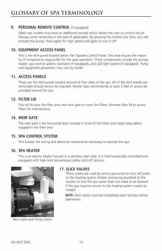
17. SLICE VALVES These valves are used by service personnel to shut off water to the heating system (heater and pump plumbed to the heater) so that the spa water does not need to be drained if the spa requires service to the heating system (varies by model).
NOTE: Slice valves must be completely open during normal operations.
Slice Valve and Pump Union

13DO NOT DIVE. 102DO NOT DIVE.
GLOSSARY OF SPA TERMINOLOGY
18. MAIN THERAPY PUMP This produces water flow through the main jets in the spa. The first pump may be operated
on two speeds (varies by model). Low speed (if applicable) will produce efficient water circu-lation during filtration, heating of the spa water, and gentle jet action. High speed provides maximum jet action. The main pump is controlled by the “Jets” or “Jets I” button on the Topside Control Panel.
19. SECONDARY THERAPY PUMP (if equipped)
This produces water flow through 1 to 2 groups or seats of jets in the spa. The second pump operates similar to the main pump and is controlled by the “Jets II” or “Aux” button on the Topside Control Panel.
20. THIRD THERAPY PUMP (if equipped)
This produces water flow through 1 to 2 groups or seats of jets in the spa. This is controlled by the Jets III button on the Topside Control Panel.
21. CIRCULATION PUMP (if equipped)
This produces water flow through the heater in the spa and provides the water flow neces-sary to actuate the ozone injector. This energy efficient pump runs 24 hours for efficient fil-tration and heating.
22. PUMP UNION These are used to help relieve possible pump air locks or for service personnel to easily service
the pumps.
23. HEATER UNION These are used by service personnel to easily service the heater.
14DO NOT DIVE. 100DO NOT DIVE.
SITE PREPARATION / GENERAL GUIDELINES
Portable spa installation is simple when properly planned. It is important that you read the follow-ing information carefully and consult with your Master Spas dealer.
1) Access - The actual dimensions of your new spa will determine the amount of space that is needed in moving the spa from curbside to its final installation area. Be sure to consider and measure side yard dimensions, gates, doors, overall room dimensions and vertical obstruc-tions such as ceilings, roof overhangs, balconies and overhead cables. Any other space limiting obstacles such as stairs, trees, and shrubs must also be evaluated. Please be sure to contact and review these site and installation plans with your Master Spas dealer prior to delivery.
2) Surface/Pad Requirements - When your new spa is filled with water and bathers, it may weigh as much as several tons. It is imperative that the base beneath the spa can support the entire weight. The spa must be on a uniformly firm, continuous, and level surface. The recommended foundation is a concrete pad with a minimum thickness of four (4) inches with steel reinforce-ment bars crossed throughout the pad.
IMPORTANTWhen installing your spa indoors, on a wood deck, roof or balcony; load requirements need to be evaluated before installation. You should speak with a qualified contractor or your local building department to confirm that your surface is adequate for supporting a spa.
All sides of the spa must be accessible for regular maintenance or in the event that service is needed. Periodical maintenance checks require entry into the equipment bay. When possible, it is wise planning for the future to leave 3 feet of access to all sides of the spa in the event your spa requires maintenance. Your spa warranty does not cover the cost of providing access for service.
GENERAL CONSIDERATIONS FOR OUTDOOR INSTALLATIONAgain, proper planning will increase your total enjoyment factor with your new spa. Listed below are some additional items to consider when planning your installation.
• How spa will complement landscaping and vice versa
• View from inside spa and view of spa from inside of home
• Exposure to sunlight and shading from trees
• Privacy
• Getting to spa from house and return
• Proximity to dressing rooms and bathrooms
• Storage for spa chemicals
• Local building codes (if applicable)
• Power cable
GENERAL CONSIDERATIONS FOR INDOOR INSTALLATIONInstalling your spa indoors creates an entirely different set of considerations.
• Work with your Master Spas dealer and contractor to insure all local building, electri-cal and plumbing codes are met
• Plan for a floor drain to drain off excess water and for draining and cleaning your spa
• A ventilation fan may be necessary due to high humidity created by your spa
• Finished material in your spa room should also be capable of withstanding increased humidity
15DO NOT DIVE. 101DO NOT DIVE.
SITE PREPARATION / GENERAL GUIDELINES
GUIDELINES FOR PARTIALLY OR FULLY RECESSED INSTALLATION Spas manufactured by Master Spas, Inc. are designed to be installed in a variety of settings. One of which is installing below grade. Should a spa be installed below the level of the site drainage system (below grade), a system for preventing water collecting and pooling must be designed based on the requirements of the local authority having jurisdiction. The drainage system must be designed based on things such as rainfall, water runoff, splashing, draining the spa, etc. that could potentially feed the below grade area with water. Where located in designated floodways, additional attention to maximum water load entering the area below grade must be addressed to prevent water from accumulating below grade at all times. It is generally recommended that the spa be installed above grade because the spa is not designed to be submerged in water. When a proper drainage system is designed based on the characteristics of the site, installing the spa below grade is an accepted method of installation.
• The unit is self-supporting when placed on a surface designed to support the full load of the spa (see Surface/Pad Requirements). Do not backfill with sand, gravel, or earth. Doing so will void the warranty.
• Plan for complete drainage so standing water never reaches the electrical equipment.
• Plan for appropriate ventilation so the equipment doesn’t overheat.
• Provide a minimum of 3 feet service area around the perimeter of the unit. Site access issues are not covered by the product warranty.
• The unit is not designed to be submerged in water. Water entering the equipment area creates many hazards and resulting damage will not be covered by the product warranty.
• Make sure that the surroundings do not create any additional hazards.
• Surfaces placed around the unit should also be evaluated for walking/slipping hazards from standing water. Proper drainage is vital to the installation of a below grade installation.
• Check all building, electrical, and plumbing codes with the authority having jurisdiction to ensure that your installation is in compliance with all local codes.
• Additional consideration needs to be made when installing unit in designed floodways.
• Verify that site specific drainage systems such as down spouts are not going to feed the area below grade.
• Below grade drainage system needs to be evaluated based on area specific rainfall. One size does not fit all so an analysis by a qualified, local engineer to ensure proper drainage of all sourc-es of water is a must when installing below grade.

16DO NOT DIVE. 100DO NOT DIVE.
INSTALLATION INSTRUCTIONS
1. Put spa in final position that allows for access to equipment and spa components. Master Spas recommends that at least 3 feet of space be provided around all sides of the spa for access. This provides adequate space for regular maintenance and service.
2. Remove front skirt panel (this is the side where the topside control panel is located) so electrical can be hooked up to the spa control system. This panel is removed by unscrewing the screws securing the skirt corners and the front skirt panel.
3. With the front skirt panels removed allowing access to the equipment, be sure all pump and heater unions are secure. Each pump has 2 unions and the heater has 2 unions. A newly delivered spa may have loose unions caused in transporting the spa. Check that all slice valves are open, in the up position. The slice valves may become closed during transportation of the spa.
4. Fill spa at least 1” above the filters or to the minimum water level indication located near the filter area. We recommend filling the spa through the filter area.
5. Turn the power on to the spa. Spa will initially display Priming Mode or “Pr”. This lasts approximately 5-6 minutes. This time is provided to allow each of the pumps to be activated and checked to ensure they are not air locked from the spa being filled.
6. Be sure the adjustable jets in your spa are open by turning the face of the jet. Most of the jets in your spa are adjustable and removable by turning the face of the jet.
Slice Valve and Pump Union
17DO NOT DIVE. 101DO NOT DIVE.
INSTALLATION INSTRUCTIONS
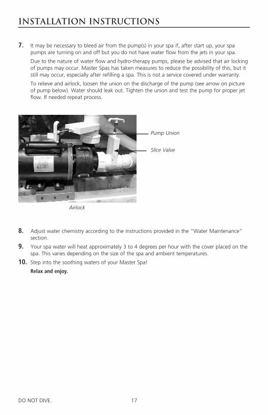
7. It may be necessary to bleed air from the pump(s) in your spa if, after start up, your spa pumps are turning on and off but you do not have water flow from the jets in your spa.
Due to the nature of water flow and hydro-therapy pumps, please be advised that air locking of pumps may occur. Master Spas has taken measures to reduce the possibility of this, but it still may occur, especially after refilling a spa. This is not a service covered under warranty.
To relieve and airlock, loosen the union on the discharge of the pump (see arrow on picture of pump below). Water should leak out. Tighten the union and test the pump for proper jet flow. If needed repeat process.
Airlock
Pump Union
Slice Valve
8. Adjust water chemistry according to the instructions provided in the “Water Maintenance” section.
9. Your spa water will heat approximately 3 to 4 degrees per hour with the cover placed on the spa. This varies depending on the size of the spa and ambient temperatures.
10. Step into the soothing waters of your Master Spa!
Relax and enjoy.

18DO NOT DIVE. 100DO NOT DIVE.
Eco Pur™ water filter system is designed to reduce the use of chemicals in your spa. You will still be required, periodically, based on usage to add a small amount of chlorine to oxidize organic compounds in the water. The Eco Pur™ filter system will not eliminate the need to maintain proper water chemistry but can make the maintenance a more natural experience.
FEATURES• The Eco Pur™ filter system will not oxidize organic compounds and will require periodic doses of
chlorine to assist in the sanitization and oxidation processes required to maintain clear spa water.
• Eco Pur™ filter system will not alter the ph of spa water. The Eco Pur™ filter system will actually aid in stabilizing the ph. Eco Pur™ does not alter the (TDS) total dissolved solids.
• The main function of the Eco Pur™ filter system is to provide clean and clear spa water. Proper chemical balance and filtration are also key components in maintaining healthy spa water. Always ensure that the ph and total alkalinity of the spa water is checked and balanced at all times. To ensure proper filtration, clean the regular filter cartridge with a “filter cleaner” every 30 days and rinse the Eco Pur™ cartridge with a hose to remove any buildup of containments. (Do not soak the Eco Pur™ cartridge in filter cleaner.) If water appears to be visually cloudy, dull, or has an odor, shock the spa water with 1 ounce of chlorine* to remove excessive containments. When cleaning filters, be sure to never have the pumps (including the circulation pump) running without the filters in place. Failure to do so may result in debris being drawn into the pumps causing unwarranted damage.
• Helps remove calcium carbonate and hydrogen sulphide from spa water to protect heaters and equipment from precipitation.
• Helps stabilize the pH and alkalinity of the spa water.
• Helps reduce chemical usage and still provide safe odor-free water.
• Helps deplete excess chlorine after chemical shock to prevent damage to skin, hair, and swim wear.
• Helps to produce ultra clean and clear water.
Note: Eco Pur™ filters are not recommended for use with Bromine. Consult your dealer for addi-tional information.
Master Spas, Inc. products are not designed to be used with Biquanides. These chemicals are found in SoftSwim® and Baqua Spa® products. Due to adverse effects from these types of sanitizers, the use of these products may void the spa warranty.
THE ADVANTAGES OF ECO PUR™ Filtration

19DO NOT DIVE. 100DO NOT DIVE.
WATER CHEMISTRY TERMS YOU SHOULD KNOW
Before jumping into Water Maintenance, here are some terms to help you.
1. Parts per million, or ppm: This is a form of measurement used in most pool or spa chemical readings. Best described as any one million like items of equal size and make up, next to one unlike item, but of equal size. This would be one part per million.
2. Average size spa: What is it? The national spa and pool institute (NSPI) states; 350 to 400 U.S. gallons is average. As a general rule, chemical dosages are the same for any spa between 100 and 500 U.S. gallons. Spas over 500 U.S. gallons the dosage would be double. Under 100 U.S. gallons would be on a case by case basis.
3. Total Alkalinity: This is a measurement of the ability of the water to resist changes in pH. Put another way, it is the water’s ability to maintain proper pH. Total alkalinity is measured in parts per million from 0 to 400 plus, with 100 to 120 ppm being the best range for spas. With low alkalinity, the pH will flip, or change back and forth, and be hard to control. With high alkalinity it becomes extremely difficult to change the pH.
4. pH or potential hydrogen: This is a measurement of the active acidity in the water, or it is the measurement of the concentration of active hydrogen ions in the water. The greater the concentration of active hydrogen ions, the lower the pH. pH is not measured in parts per mil-lion, but on a scale from 0 to 14, with 7 being the neutral. The pH in spas should be ideally maintained between 7.4 to 7.6. It should never be below 7.2 or above 7.8. With low pH, the results can be corroded metals, etched and stained plaster stained fiberglass or acrylic, eye / skin irritation, rapid chlorine or bromine loss, and total alkalinity destruction. With high pH, the results can be cloudy water, eye / skin irritation, scale formation and poor chlorine or bro-mine efficiency.
5. Shocking: This is when you add either extra chlorine (superchlorinate) by raising the chlorine level above 8 ppm, or add a non-chlorine /oxidizer (potassium monoperoxysulfate or potassi-um monopersulfate) to burn off the chloramines or bromamines. A non-chlorine /oxidizer acts by releasing oxygen in the water, which serves the same function as chlorine. The advantage to using non-chlorine /oxidizer, is you can enter the water within 15 minutes after application. Using chlorine, you must wait until the total chlorine reading is below 5 ppm. One thing to remember, a non-chlorine /oxidizer will not kill bacteria or disinfect.
6. Sequestering: This can be defined as the ability to form a chemical complex which remains in solution, despite the presence of a precipitating agent (i.e. calcium and metals). Common names for sequestering chemicals are; minquest, stain and scale control, metal-x, spa defend-er, spa metal gone, (etc.).
7. Filtration: Filters are necessary to remove particles of dust, dirt, algae, etc. that are continu-ously entering the water. If the spa is not operated long enough each day for the filter to do a proper job, this puts a burden on the chemicals, causing extra expense. Filtration time will depend on the spa size, pump and filter size and, of course, bather load. Spare filter cartridg-es should be kept on hand to make it easy to frequently clean the cartridge without the need for a long shut down. This will also allow the cartridge to dry out between usages, which will increase the cartridge life span as much as twice. Replace the cartridge when the pleats begin to deteriorate. Cartridge cleaning should be done a minimum of once a month. More often with a heavy bather load.
20DO NOT DIVE. 101DO NOT DIVE.
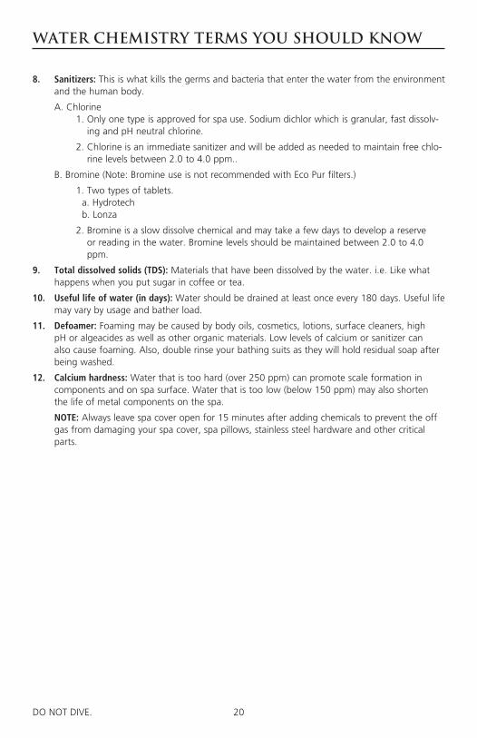
8. Sanitizers: This is what kills the germs and bacteria that enter the water from the environment and the human body.
A. Chlorine 1. Only one type is approved for spa use. Sodium dichlor which is granular, fast dissolv-
ing and pH neutral chlorine.
2. Chlorine is an immediate sanitizer and will be added as needed to maintain free chlo-rine levels between 2.0 to 4.0 ppm..
B. Bromine (Note: Bromine use is not recommended with Eco Pur filters.)
1. Two types of tablets. a. Hydrotech b. Lonza
2. Bromine is a slow dissolve chemical and may take a few days to develop a reserve or reading in the water. Bromine levels should be maintained between 2.0 to 4.0 ppm.
9. Total dissolved solids (TDS): Materials that have been dissolved by the water. i.e. Like what happens when you put sugar in coffee or tea.
10. Useful life of water (in days): Water should be drained at least once every 180 days. Useful life may vary by usage and bather load.
11. Defoamer: Foaming may be caused by body oils, cosmetics, lotions, surface cleaners, high pH or algeacides as well as other organic materials. Low levels of calcium or sanitizer can also cause foaming. Also, double rinse your bathing suits as they will hold residual soap after being washed.
12. Calcium hardness: Water that is too hard (over 250 ppm) can promote scale formation in components and on spa surface. Water that is too low (below 150 ppm) may also shorten the life of metal components on the spa.
NOTE: Always leave spa cover open for 15 minutes after adding chemicals to prevent the off gas from damaging your spa cover, spa pillows, stainless steel hardware and other critical parts.
WATER CHEMISTRY TERMS YOU SHOULD KNOW
21DO NOT DIVE. 100DO NOT DIVE.
WHY ARE CHEMICALS IMPORTANT IN A SPA
1. Evaporation: As water evaporates, only pure water evaporates, leaving the salts, minerals, metals, and any
unused chemicals behind. Adding water adds more salts, minerals, and metals. In time, the water can become saturated with these dissolved solids and can cause stains or scale to form on the walls of the spa or a scale build up inside the equipment. Colored or cloudy water, and possible corrosion of plumbing and fittings may also occur.
2. Heat: Heat causes much quicker evaporation and also will cause minerals and metals to precipitate
out of solution.
3. Air: Dust and other airborne contaminants are introduced into the spa.
4. Environment: The environment surrounding the spa can also impact the water quality. Items such as pol-
len, grass, sand, dirt, lawn fertilizer, airborne dust, insects, leaves, and pets can all affect the water quality of the spa.
5. Bathers: As the spa is used, bathers introduce contaminants to the water. Increased bather load,
length of use and frequency will increase the amounts of contaminants added in to the water.
Remember: The maintenance routines set forth in this manual may need to be adjusted depending on bather load and how much the spa is being used.

22DO NOT DIVE. 100DO NOT DIVE.
Step 1: Your spa should be filled using a Pre-filter, which can be obtained from your local dealer. This Pre-filter will help remove many of the minerals existing in the water, which will make adjusting the water balance easier after a new fill. Never use more then 50% softened water when filling the spa.
Step 2: During the initial filling of the spa, add a sequestering agent to combat suspended minerals in the water. The agents are sold under many different names such as Mineral Clear, Stain and Scale, Metal Protect, and other brands. Allow water to circulate and filter for at least 12 hours before adding any other chemicals.
Step 3: Test water for pH, total Alkalinity, and Calcium hardness. The pH should be 7.4 - 7.6 and the total Alkalinity 100 - 120 ppm. Calcium hardness levels should be maintained between 150 and 250 ppm (part per million).
Step 4: Adjust pH and total Alkalinity (TA) utilizing the directions on the chemical bottles. Wait 15 minutes, test and adjust if necessary.
Step 5: It may be necessary to retest and add additional chemicals to get to the proper levels in Step 3.
Step 6: Add concentrated chlorinating granules* (sodium Dichlor-s-triazinetreone) to reach a Free Chlorine level of 5 to 8 ppm on initial start up to begin sanitizing the spa water. Bathers should not enter the spa until the chlorine levels drop below 5.0 ppm. Always refer to the chemical manufactures dosage recommendations listed on the container. It is important not to add the chlorinating granules until the pH, alkalinity and calcium hardness have been adjusted to their proper levels.
*SPECIAL NOTE:We recommend a minimum level of 2.0 ppm residual free chlorine be maintained in spa water. Always refer to the chemical manufacturer’s dosage recommendations listed on the container.
When adding chlorine or non-chlorine shock/oxidizer always broadcast across the water while the pumps are running.
The quantities of sanitizer and oxidizer shown in this manual are for 500 gallon spas and may have to be adjust-ed depending on the actual amount of water that your spa holds. See the specifications section of this manual for the correct gallons of your spa.
The concentration of active ingredients in spa chemicals varies by manufacturer. The amounts of sanitizer sug-gested in this manual are based on spa chemicals that have the active ingredient percentages listed below:
Chlorine Non-Chlorine Shock/ Oxidizer
Active ingredient: Active ingredient:
Sodium dichlor ................................. 99% Potassium peroxymonosulfate ....................... 42.8%
Other ingredients ................................ 1% Inert ingredients ............................................ 57.2%
Total ............................................... 100% Total............................................................ 100%
WATER MAINTENANCE – START-UP
23DO NOT DIVE. 100DO NOT DIVE.
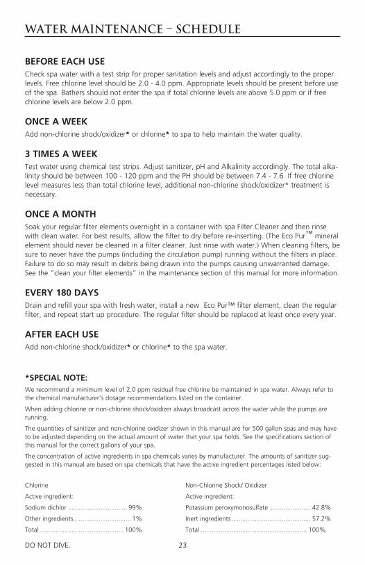
BEFORE EACH USE Check spa water with a test strip for proper sanitation levels and adjust accordingly to the proper levels. Free chlorine level should be 2.0 - 4.0 ppm. Appropriate levels should be present before use of the spa. Bathers should not enter the spa if total chlorine levels are above 5.0 ppm or if free chlorine levels are below 2.0 ppm.
ONCE A WEEK Add non-chlorine shock/oxidizer* or chlorine* to spa to help maintain the water quality.
3 TIMES A WEEKTest water using chemical test strips. Adjust sanitizer, pH and Alkalinity accordingly. The total alka-linity should be between 100 - 120 ppm and the PH should be between 7.4 - 7.6. If free chlorine level measures less than total chlorine level, additional non-chlorine shock/oxidizer* treatment is necessary.
ONCE A MONTHSoak your regular filter elements overnight in a container with spa Filter Cleaner and then rinse with clean water. For best results, allow the filter to dry before re-inserting. (The Eco Pur™ mineral element should never be cleaned in a filter cleaner. Just rinse with water.) When cleaning filters, be sure to never have the pumps (including the circulation pump) running without the filters in place. Failure to do so may result in debris being drawn into the pumps causing unwarranted damage. See the “clean your filter elements” in the maintenance section of this manual for more information.
EVERY 180 DAYSDrain and refill your spa with fresh water, install a new Eco Pur™ filter element, clean the regular filter, and repeat start up procedure. The regular filter should be replaced at least once every year.
AFTER EACH USEAdd non-chlorine shock/oxidizer* or chlorine* to the spa water.
WATER MAINTENANCE – SCHEDULE
*SPECIAL NOTE:We recommend a minimum level of 2.0 ppm residual free chlorine be maintained in spa water. Always refer to the chemical manufacturer’s dosage recommendations listed on the container.
When adding chlorine or non-chlorine shock/oxidizer always broadcast across the water while the pumps are running.
The quantities of sanitizer and non-chlorine oxidizer shown in this manual are for 500 gallon spas and may have to be adjusted depending on the actual amount of water that your spa holds. See the specifications section of this manual for the correct gallons of your spa.
The concentration of active ingredients in spa chemicals varies by manufacturer. The amounts of sanitizer sug-gested in this manual are based on spa chemicals that have the active ingredient percentages listed below:
Chlorine Non-Chlorine Shock/ Oxidizer
Active ingredient: Active ingredient:
Sodium dichlor ................................. 99% Potassium peroxymonosulfate ....................... 42.8%
Other ingredients ................................ 1% Inert ingredients ............................................ 57.2%
Total ............................................... 100% Total............................................................ 100%

24DO NOT DIVE. 101DO NOT DIVE.
WATER MAINTENANCE – SCHEDULE
AS NEEDEDIf water looks hazy, check PH and Total Alkilinity, and treat with chlorine*. Always refer to the chemical manufactures dosage recommendations listed on the container. Free chlorine levels should be maintained between 2.0 - 4.0 ppm.
These are general recommendations for water maintenance that may vary by usage and bather load. Depending on bather load and frequency of use, drain and refill times may vary as well as the frequency of cleaning your filters.
A defoamer may be used when excessive foaming occurs. Over use of a defoamer will result in cloudy, milky water.
USE ONLY SPA CHEMICALSDo not use chemicals designed for use in swimming pools.
With a spa you are working with a small volume of hot water compared to a large volume of relatively cool water in a swimming pool. Because of this chemicals will have a shorted life span and bacteria can grow more quickly than in a swimming pool. A spa is less forgiving then a pool and requires that whatever is put into it have a pH as close to neutral as possible. That is why only chemicals made for spas should be used. Always refer to the chemical manufactures dosage rec-ommendations listed on the container.
*SPECIAL NOTE:We recommend a minimum level of 2.0 ppm residual free chlorine be maintained in spa water. Always refer to the chemical manufacturer’s dosage recommendations listed on the container.
When adding chlorine or non-chlorine shock/oxidizer always broadcast across the water while the pumps are running.
The quantities of sanitizer and oxidizer shown in this manual are for 500 gallon spas and may have to be adjust-ed depending on the actual amount of water that your spa holds. See the specifications section of this manual for the correct gallons of your spa.
The concentration of active ingredients in spa chemicals varies by manufacturer. The amounts of sanitizer sug-gested in this manual are based on spa chemicals that have the active ingredient percentages listed below:
Chlorine Non-Chlorine Shock/ Oxidizer
Active ingredient: Active ingredient:
Sodium dichlor ................................. 99% Potassium peroxymonosulfate ....................... 42.8%
Other ingredients ................................ 1% Inert ingredients ............................................ 57.2%
Total ............................................... 100% Total............................................................ 100%
25DO NOT DIVE. 100DO NOT DIVE.
WATER MAINTENANCE – TROUBLE-SHOOTING GUIDE
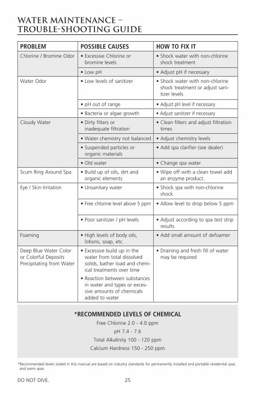
*RECOMMENDED LEVELS OF CHEMICALFree Chlorine 2.0 - 4.0 ppm
pH 7.4 - 7.6
Total Alkalinity 100 - 120 ppm
Calcium Hardness 150 - 250 ppm
PROBLEM POSSIBLE CAUSES HOW TO FIX ITChlorine / Bromine Odor • Excessive Chlorine or
bromine levels• Shock water with non-chlorine
shock treatment
• Low pH • Adjust pH if necessary
Water Odor • Low levels of sanitizer • Shock water with non-chlorine shock treatment or adjust sani-tizer levels
• pH out of range • Adjust pH level if necessary
• Bacteria or algae growth • Adjust sanitizer if necessary
Cloudy Water • Dirty filters or inadequate filtration
• Clean filters and adjust filtration times
• Water chemistry not balanced • Adjust chemistry levels
• Suspended particles or organic materials
• Add spa clarifier (see dealer)
• Old water • Change spa water
Scum Ring Around Spa • Build up of oils, dirt and organic elements
• Wipe off with a clean towel add an enzyme product.
Eye / Skin Irritation • Unsanitary water • Shock spa with non-chlorine shock
• Free chlorine level above 5 ppm • Allow level to drop below 5 ppm
• Poor sanitizer / pH levels • Adjust according to spa test strip results
Foaming • High levels of body oils, lotions, soap, etc.
• Add small amount of defoamer
Deep Blue Water Color or Colorful Deposits Precipitating from Water
• Excessive build up in the water from total dissolved solids, bather load and chem-ical treatments over time
• Reaction between substances in water and types or exces-sive amounts of chemicals added to water
• Draining and fresh fill of water may be required
* Recommended levels stated in this manual are based on industry standards for permanently installed and portable residential spas and swim spas.
26DO NOT DIVE. 100DO NOT DIVE.
Regular Maintenance Procedures
Note: These are areas that will require the spa owner to perform routine maintenance. These are not areas covered under the warranty of the spa.
Your spa requires periodic draining and cleaning to ensure a safe, healthy environment. It is recom-mended that you clean your spa at least every 180 days or as necessary. Heavy bather load will require cleaning it more often.
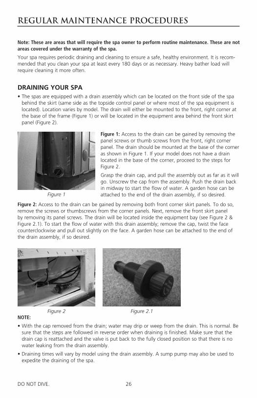
DRAINING YOUR SPA• The spas are equipped with a drain assembly which can be located on the front side of the spa
behind the skirt (same side as the topside control panel or where most of the spa equipment is located). Location varies by model. The drain will either be mounted to the front, right corner at the base of the frame (Figure 1) or will be located in the equipment area behind the front skirt panel (Figure 2).
Figure 1
Figure 2 Figure 2.1
Figure 1: Access to the drain can be gained by removing the panel screws or thumb screws from the front, right corner panel. The drain should be mounted at the base of the corner as shown in Figure 1. If your model does not have a drain located in the base of the corner, proceed to the steps for Figure 2.
Grasp the drain cap, and pull the assembly out as far as it will go. Unscrew the cap from the assembly. Push the drain back in midway to start the flow of water. A garden hose can be attached to the end of the drain assembly, if so desired.
Figure 2: Access to the drain can be gained by removing both front corner skirt panels. To do so, remove the screws or thumbscrews from the corner panels. Next, remove the front skirt panel by removing its panel screws. The drain will be located inside the equipment bay (see Figure 2 & Figure 2.1). To start the flow of water with this drain assembly; remove the cap, twist the face counterclockwise and pull out slightly on the face. A garden hose can be attached to the end of the drain assembly, if so desired.
NOTE:
• With the cap removed from the drain; water may drip or weep from the drain. This is normal. Be sure that the steps are followed in reverse order when draining is finished. Make sure that the drain cap is reattached and the valve is put back to the fully closed position so that there is no water leaking from the drain assembly.
• Draining times will vary by model using the drain assembly. A sump pump may also be used to expedite the draining of the spa.

27DO NOT DIVE. 101DO NOT DIVE.
REGULAR MAINTENANCE PROCEDURES
CLEAN YOUR SPA SURFACE• With a soft cloth, wipe down the spa surface with a non-abrasive spa surface cleaner that may
be purchased through your local spa dealer. Do not use paper towels. Be sure to rinse residue from spa surface.
• If your spa has developed an oily or chalky residue at the waterline it may require special treat-ment. Consult your dealer.
CLEAN YOUR FILTER ELEMENTSThe filter elements are one of the most important components of your spa. Not only are they essential for clean water, but they also extend the life of the spa equipment. Your filter elements should be cleaned on a regular basis, once a month on average with normal usage. With heavy use the filters may need to be cleaned more often.
• Turn off the spa before servicing filters. Never leave to the spa running when removing the fil-ters. Debris can be pulled into the plumbing system and cause unwarranted damage.
• Remove filter element(s).
• With a garden hose, spray each element under pressure. Periodically, the standard filter elements need to be soaked in a filter cleaner compound. Do not soak Eco Pur mineral filters in a filter cleaner. Eco Pur filters should only be rinsed with fresh, clean water as necessary. Check with your dealer for details on cleaning and/or filter replacement recommendations.
• The Eco Pur Mineral filter should be replaced every 6 months. The standard filter should be cleaned regularly and will typically last approximately 1 year. Bather load, usage and water qual-ity will effect the longevity of the filters and require more frequent cleaning or replacement.
CARE OF YOUR SPA PILLOWS• Your spa pillows need to be rinsed periodically to remove any chemical residue. This should help
to eliminate pillows becoming stiff and discolored.
• If spa is not to be used for a period of time, pillows should be removed. Pillow life will be extended.
NOTE: Do not cover the spa for 15 minutes after adding chemicals as the off gas can cause unwar-ranted damage.
Note: These are areas that will require the spa owner to perform routine maintenance. These are not areas covered under the warranty of the spa.
28DO NOT DIVE. 102DO NOT DIVE.
REGULAR MAINTENANCE PROCEDURES
Note: These are areas that will require the spa owner to perform routine maintenance. These are not areas covered under the warranty of the spa.
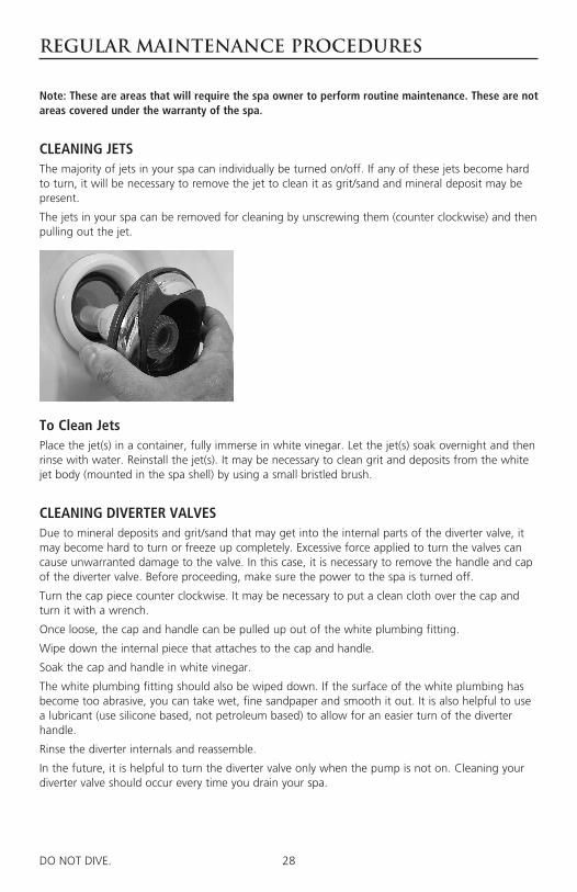
CLEANING JETSThe majority of jets in your spa can individually be turned on/off. If any of these jets become hard to turn, it will be necessary to remove the jet to clean it as grit/sand and mineral deposit may be present.
The jets in your spa can be removed for cleaning by unscrewing them (counter clockwise) and then pulling out the jet.
To Clean JetsPlace the jet(s) in a container, fully immerse in white vinegar. Let the jet(s) soak overnight and then rinse with water. Reinstall the jet(s). It may be necessary to clean grit and deposits from the white jet body (mounted in the spa shell) by using a small bristled brush.
CLEANING DIVERTER VALVESDue to mineral deposits and grit/sand that may get into the internal parts of the diverter valve, it may become hard to turn or freeze up completely. Excessive force applied to turn the valves can cause unwarranted damage to the valve. In this case, it is necessary to remove the handle and cap of the diverter valve. Before proceeding, make sure the power to the spa is turned off.
Turn the cap piece counter clockwise. It may be necessary to put a clean cloth over the cap and turn it with a wrench.
Once loose, the cap and handle can be pulled up out of the white plumbing fitting.
Wipe down the internal piece that attaches to the cap and handle.
Soak the cap and handle in white vinegar.
The white plumbing fitting should also be wiped down. If the surface of the white plumbing has become too abrasive, you can take wet, fine sandpaper and smooth it out. It is also helpful to use a lubricant (use silicone based, not petroleum based) to allow for an easier turn of the diverter handle.
Rinse the diverter internals and reassemble.
In the future, it is helpful to turn the diverter valve only when the pump is not on. Cleaning your diverter valve should occur every time you drain your spa.
29DO NOT DIVE. 103DO NOT DIVE.
REGULAR MAINTENANCE PROCEDURES
CARE OF YOUR SPA COVERAlways cover your spa when not in use. This will greatly reduce energy consumption and will cause spa water to heat more rapidly. Water loss and chemical usage will also be reduced.
• Be sure to lock down all straps on cover after each use to prevent wind damage.
• Do not allow spa to sit uncovered in direct sunlight. This may cause damage to exposed surfaces and components of the spa and possible discoloration of spa fittings.
• Periodically hose off both sides of spa cover for maximum life of cover. Once a month use a vinyl cleaner and conditioner on the vinyl portion of your cover. Rinse residue off.
• Keep cover open for 15 minutes after adding chemicals to prevent off gas damage.
NOTE: if your spa is going to be left empty for prolonged periods, do not replace cover directly on surface of spa. Place 2”-3” blocks between cover and spa. This allows for adequate ventila-tion of cover and spa.
NOTE: The cover warranty is not part of the limited warranty provided with the spa. It is provided through the cover manufacturer and may not be through Master Spas. Check the tags and labeling on your cover to verify manufacturer and refer to the manufacturer’s care, mainte-nance and warranty information. Your dealer can help provide you with these details.
NOTE: To prevent premature failure of your spa cover, always turn water feature valve down so that the water features do not hit the cover when the cover is closed.
CARE OF YOUR SPA CABINETYour skirt is maintenance free. No conditioning is necessary. Simply rinse off the waterproof / U.V. resistant material periodically with fresh, clean water.
CARE OF YOUR OZONE SYSTEMThe ozone hose and check valve connecting between the ozone generator and ozone injector should be inspected and/or replaced, if necessary, every 12 months. Depending on conditions of the air which is being brought in to the ozone generator, the ozone hose and check valve can wear more rapidly. This regular maintenance is not covered under the spa warranty. Your Master Spas Dealer or Service Center can be contacted to schedule this maintenance.
Note: These are areas that will require the spa owner to perform routine maintenance. These are not areas covered under the warranty of the spa.

30DO NOT DIVE. 104DO NOT DIVE.
Regular Maintenance Procedures
Note: These are areas that will require the spa owner to perform routine maintenance. These are not areas covered under the warranty of the spa.
STAINLESS STEEL Master Spas uses stainless steel in a number of our spas. Its lasting beauty and resistance to corro-sion make it an excellent material for handrails and jets faces.
With the proper care it will keep its luster for many years. All stainless steel can corrode given the right circumstances so we have provided a guide to help you keep the stainless components in your spa looking nice.
Stainless steel derives its ability to resist corrosion by forming a very thin transparent coating on the surface when exposed to oxygen. This coating can be damaged by abrasive materials such as steel wool, sand paper, and other cleaning materials that are abrasive. Chlorine salts, sulfides, or other rusting metals can also erode this thin coating exposing the metal to corrosion.
The best defense to combat corrosion on stainless steel components in your spa is make sure that it is kept clean and free of any chemical build up.
Always:
• Clean frequently with clear, clean, non-chlorinated water.
• Remove any rust spots as soon as they appear with vinegar or a brass, silver, or chrome cleaner.
• Use a good car cleaning wax for extra protection.
• Leave cover removed from the for at least 15 minutes after adding chemicals to the spa water.
Never:
• Clean with mineral acids or bleaches.
• Clean with steel wool or any other abrasive material.
• Leave in contact with iron, steel any other metals.
• Close the cover immediately after adding chemicals to the water.
NOTE: Failure to take proper care of the stainless steel fixture could result with them rusting. Rusting is not covered by the warranty.
NOTE: Do not cover the spa for 15 minutes after adding chemicals as the off gas can cause unwarranted damage. Larger dosages can require longer lengths of time to off gas. It is recommended to check spa water more frequently to allow small dos-ages be added as necessary verse large dosages being added less often.
31DO NOT DIVE. 100DO NOT DIVE.
SPA TROUBLE SHOOTING GUIDE
Note: For wiring outside of U.S. and Canada, GFCI may be referred to as a RCD (residual current device). Be sure all local electrical codes are followed.
NOTHING ON THE SPA OPERATES1. Check the control panel display for any messages. If there is a message, refer to the diagnostic
section on that model spa. There you will find the meaning of the message and what action is to be taken.
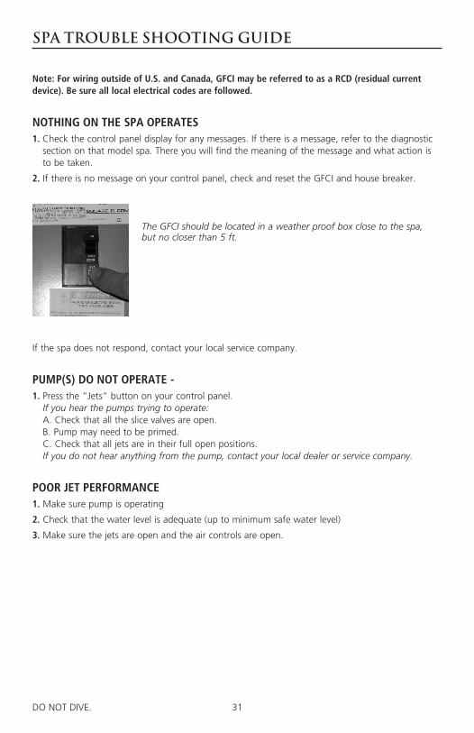
2. If there is no message on your control panel, check and reset the GFCI and house breaker.
The GFCI should be located in a weather proof box close to the spa, but no closer than 5 ft.
If the spa does not respond, contact your local service company.
PUMP(S) DO NOT OPERATE - 1. Press the “Jets” button on your control panel.
If you hear the pumps trying to operate: A. Check that all the slice valves are open. B. Pump may need to be primed. C. Check that all jets are in their full open positions. If you do not hear anything from the pump, contact your local dealer or service company.
POOR JET PERFORMANCE1. Make sure pump is operating
2. Check that the water level is adequate (up to minimum safe water level)
3. Make sure the jets are open and the air controls are open.

32DO NOT DIVE. 101DO NOT DIVE.
SPA TROUBLE SHOOTING GUIDE
Note: For wiring outside of U.S. and Canada, GFCI may be referred to as a RCD (residual current device). Be sure all local electrical codes are followed.
SPA NOT HEATING If the spas heater has failed, the majority of the time it will trip the GFCI breaker. If the spa is not heating and has not tripped the breaker, please follow these steps:
1. Check the topside control panel for diagnostic messages. Refer to your spa models diagnostic message area. Follow steps to alleviate message.
2. Check water set temperature at topside control panel.
3. Check for dirty filters. Clean or replace if necessary.
4. Check “heat mode” the spa is set in. Spa should be in standard/ready mode.
5. Check the control panel for heater indicator, see controls section of manual. If the indicator is on, the spa should be heating. With the cover closed on the spa, wait a reasonable amount of time (approximately 1 to 2 hours) to see if the water temperature is increasing.
6. Check to make sure that the pump is primed and all slice valves are open.
7. Reset power to the spa at GFCI breaker.
8. If spa is still not heating, contact your dealer for service.
GFCI IS TRIPPINGA ground fault circuit interrupter (GFCI) is required by the National Electrical Code for your protection. The tripping of the GFCI may be caused by a component on the spa or by an electrical problem. Electrical problems include but are not limited to, a faulty GFCI breaker, spa component, power fluctuations, or improper wiring. If this is a new electrical service and GFCI installation, an instantly tripping GFCI may likely be caused by improper wiring of the load neutral from the GFCI to the spa. It may be necessary to contact an electrician if your dealer recommends doing so.

33DO NOT DIVE. 100DO NOT DIVE.
Winterizing & Storing Your Spa
Winterizing Your SpaMany people find they enjoy using their spa more in the winter than any other time. Your spa is designed to be used year round in any type of climate.
* However, if you decide you don’t want to use your spa in the winter, you must drain it and fol-low the winterizing steps listed below:
1. Drain your spa completely using the drain valve (if so equipped) or use an inexpensive sub-mersible pump that you can buy from your dealer or your local hardware store.
2. Use a shop vac to get all standing water out of your unit.
3. Remove access panels from equipment area.
4. Loosen and disconnect all pump unions and heater unions.
5. Remove winterizing plug from face of the pump(s) where applicable.
6. Using your shop vac in a blowing mode, insert the hose into the nozzle of each jet and blow the trapped water from the lines into the interior of the spa. A non-toxic, RV water line type antifreeze can be used and added to jets in each seat around your spa to help prevent freeze damage from occurring. Be sure to thoroughly flush the system before startup.
7. After this is completed, use the shop vac to remove any standing water in the spa and in the equipment area.
8. Clean the spa with a soft cloth and a non-abrasive spa surface cleaner.
9. Replace access panels.
10. Cover spa to prevent water from entering the spa.
* Disclaimer: Master Spas does not recommend winterizing your spa. If you choose to do so, any damage that may result is not covered under the spa warranty.
Storing Your SpaThe spa shell should never be left unprotected and uninsulated while being stored. Clear plastic wrap or similar material should never be used to cover/protect the spa.
Prolonged, direct sun heat can damage the surfaces of the spa along with any components on the spas surface. Always keep the spa covered and protected with an insulating spa cover. Resulting damage such as cracking in the shell surface or warped or discolored components on the spa shell would not be warranted.
An empty spa should never be exposed to temperatures below 0°F (-18°C) after delivery as extreme cold can cause shell damage. This includes storage and draining (winterizing). If your spa can be exposed to these temperatures, keep the unit filled and running. If you do not plan to use your spa, you can set the spa to the lowest temperature setting allowed by the control system.
Failure to adhere to these guidelines will void the warranty.

34DO NOT DIVE. 100DO NOT DIVE.
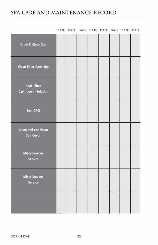
SPA CARE AND MAINTENANCE RECORD
DATE
Drain & Clean Spa
Clean Filter Cartridge
Test GFCI
Soak Filter
Cartridge in Solution
Clean and Condition
Spa Cover
Miscellaneous
Service
Miscellaneous
Service
DATE DATE DATE DATE DATE DATE DATE
35DO NOT DIVE. 100DO NOT DIVE.
SPA CARE AND MAINTENANCE RECORD
DATE
Drain & Clean Spa
Clean Filter Cartridge
Test GFCI
Soak Filter
Cartridge in Solution
Clean and Condition
Spa Cover
Miscellaneous
Service
Miscellaneous
Service
DATE DATE DATE DATE DATE DATE DATE
36DO NOT DIVE. 100DO NOT DIVE.
ELECTRICAL REQUIREMENTS
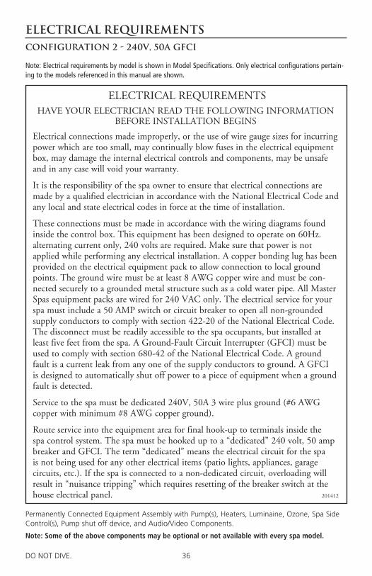
Permanently Connected Equipment Assembly with Pump(s), Heaters, Luminaine, Ozone, Spa Side Control(s), Pump shut off device, and Audio/Video Components.
Note: Some of the above components may be optional or not available with every spa model.
ELECTRICAL REQUIREMENTSHAVE YOUR ELECTRICIAN READ THE FOLLOWING INFORMATION
BEFORE INSTALLATION BEGINS
Electrical connections made improperly, or the use of wire gauge sizes for incurring power which are too small, may continually blow fuses in the electrical equipment box, may damage the internal electrical controls and components, may be unsafe and in any case will void your warranty.
It is the responsibility of the spa owner to ensure that electrical connections are made by a qualified electrician in accordance with the National Electrical Code and any local and state electrical codes in force at the time of installation.
These connections must be made in accordance with the wiring diagrams found inside the control box. This equipment has been designed to operate on 60Hz. alternating current only, 240 volts are required. Make sure that power is not applied while performing any electrical installation. A copper bonding lug has been provided on the electrical equipment pack to allow connection to local ground points. The ground wire must be at least 8 AWG copper wire and must be con-nected securely to a grounded metal structure such as a cold water pipe. All Master Spas equipment packs are wired for 240 VAC only. The electrical service for your spa must include a 50 AMP switch or circuit breaker to open all non-grounded supply conductors to comply with section 422-20 of the National Electrical Code. The disconnect must be readily accessible to the spa occupants, but installed at least five feet from the spa. A Ground-Fault Circuit Interrupter (GFCI) must be used to comply with section 680-42 of the National Electrical Code. A ground fault is a current leak from any one of the supply conductors to ground. A GFCI is designed to automatically shut off power to a piece of equipment when a ground fault is detected.
Service to the spa must be dedicated 240V, 50A 3 wire plus ground (#6 AWG copper with minimum #8 AWG copper ground).
Route service into the equipment area for final hook-up to terminals inside the spa control system. The spa must be hooked up to a “dedicated” 240 volt, 50 amp breaker and GFCI. The term “dedicated” means the electrical circuit for the spa is not being used for any other electrical items (patio lights, appliances, garage circuits, etc.). If the spa is connected to a non-dedicated circuit, overloading will result in “nuisance tripping” which requires resetting of the breaker switch at the house electrical panel. 201412
Configuration 2 - 240V, 50A GFCI
Note: Electrical requirements by model is shown in Model Specifications. Only electrical configurations pertain-ing to the models referenced in this manual are shown.

37DO NOT DIVE. 101DO NOT DIVE.
CONFIGURATION 2240V, 50A GFCI
*SPA CONTROL SYSTEM
50 AMP GFCI
MAIN ELECTRICAL PANEL (HOUSE)
KeyWHT - White Neutral
BLK - Black Hot, Line 1
RED - Red Hot, Line 2
GND - Ground
WHT
BLK
GNDRED
RED
WHT
GND
BLK
*Refer to wiring diagram inside spa control system for proper power connection to terminals.
GND
RED
BLK
WHT
RED
GND
BLK
WHTWHT
50
50ATEST
ELECTRICAL REQUIREMENTSConfiguration 2 - 240V, 50A GFCI

38DO NOT DIVE.
Model SPECIFICATIONS
Model Listing Number
Spa Dimensions 1Electrical Requirements
Seating Capacity
Water Capacity (gallons)
Weight Dry / 2Full (lbs.)
Therapy Pumps
TS 240 6200 78" x 78" x 34" Configuration # 2 240V, 50A GFCI
2 - 3 205 515 / 2780
2
TS 6.2 5300 78" x 78" x 34" Configuration # 2 240V, 50A GFCI
5 250 630 / 3640
2
TS 67.25 8000 70" x 84" x 34" Configuration # 2 240V, 50A GFCI
4 - 5 245 530 / 3500
2
TS 7.2 5500 84" x 84" x 38" Configuration # 2 240V, 50A GFCI
5 - 6 305 755 / 4410
2
TS 7.25 6400 84" x 84" x 38" Configuration # 2 240V, 50A GFCI
6 - 7 305 785 / 4625
2
TS 8.2 5700 94" x 94" 38" Configuration # 2 240V, 50A GFCI
6 380 755 / 5035
2
TS 8.25 7700 94" x 94" 38" Configuration # 2 240V, 50A GFCI
7 395 755 / 5345
2
TS 8.3 6000 94" x 94" 38" Configuration # 2 240V, 50A GFCI
6 385 805 / 5130
3
TS 8.35 7800 94" x 94" 38" Configuration # 2 240V, 50A GFCI
7 400 805 / 5440
3
TS 87.3 1450 94" x 84" 38" Configuration # 2 240V, 50A GFCI
5 310 780 / 3370
3
1See Electrical Requirements Section. 2Full weight based on dry weight of spa, max seating capacity of spa, assumed average weight per person of 185 pounds and estimated water weight of 8.34 pounds per gallon.

39DO NOT DIVE.
SPA CONTROLSThe Main Screen
SPA STATUSImportant information about spa operation can be seen quickly from the Main Screen.
The most important features, including Set Temperature adjustment, can be accessed from this screen.
The actual water temperature can be seen in large text and the desired, or Set Temperature, can be selected and adjusted.
Time-of-day, Ozone operation and Filter Operation status is available, along with other messages and alerts.
High Temperature Range vs. Low Temperature Range is indicated in the upper right corner.
The Jets Icon in the center will indicate when a pump is running and also the heater function.
A Lock icon is visible if the panel or settings are locked.
The Menu choices on the right can be selected and the screen will change to show more detailed controls or programming functions.
Water Temperature
Messages
Desired Temperature
Temperature Range
Pump and Heat
Menus
Lock Indicator
Status
Set: 104°F8:32 PMOzoneFilter 1
Spa
Settings
High Range102°F
Ready in Rest ModeHeating
Scene
40DO NOT DIVE.
SPA CONTROLSThe Main Screen
Set: 104°F8:32 PMOzoneFilter 1
SpaSettings
High Range102°F
Ready in Rest ModeHeating
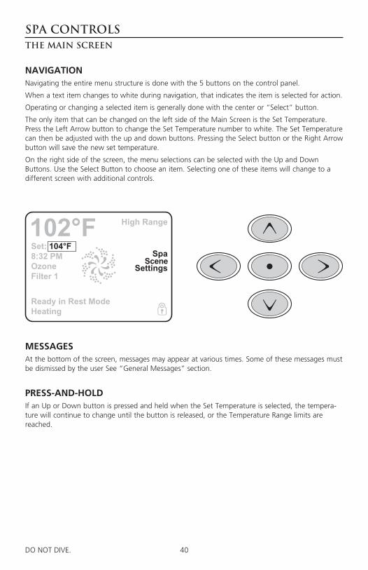
NAVIGATIONNavigating the entire menu structure is done with the 5 buttons on the control panel.
When a text item changes to white during navigation, that indicates the item is selected for action.
Operating or changing a selected item is generally done with the center or “Select” button.
The only item that can be changed on the left side of the Main Screen is the Set Temperature. Press the Left Arrow button to change the Set Temperature number to white. The Set Temperature can then be adjusted with the up and down buttons. Pressing the Select button or the Right Arrow button will save the new set temperature.
On the right side of the screen, the menu selections can be selected with the Up and Down Buttons. Use the Select Button to choose an item. Selecting one of these items will change to a different screen with additional controls.
MESSAGESAt the bottom of the screen, messages may appear at various times. Some of these messages must be dismissed by the user See “General Messages” section.
PRESS-AND-HOLDIf an Up or Down button is pressed and held when the Set Temperature is selected, the tempera-ture will continue to change until the button is released, or the Temperature Range limits are reached.
Scene

41DO NOT DIVE.
SPA CONTROLSThe Spa Screen & Scenes
Ready in Rest ModeHeating
Back
Invert
Jets HighJets LowJets Off
ALL EQUIPMENT ACCESSThe Spa Screen shows all available equipment to control, as well as other features, like Invert, in one easy-to-navigate screen. The display shows icons that are related to the equipment installed on a particular spa model, so this screen may change depending on the installation.
The navigation buttons are used to select an individual device. The device that is chosen is high-lighted with a white outline and the text under the icon changes to white. Once a device is select-ed, it can be controlled using the center Select Button.
Some devices, like pumps, may have more than one ON state, so the icon will change to reflect the state that the equipment is in. Below are some examples of 2-speed Pump indicators.
If the Spa has a 24 hour Circ Pump, a Circ Pump Icon will appear to indicate its activity, but out-side of Priming Mode, the 24 hour Circ Pump cannot be controlled directly.
NOTE: The icon for the 24 hour pump that is associated with the heater will have a red glow in the center when the heater is running.
Jets 1 Jets 2 Jets 3 Light
SCENESThe scenes area will allow you to preset any of the devices to operate when the scene is activated. There are four different scenes that can be preset. For example if you would like all of the pumps to turn on at the same time: turn on the pumps, access the scenes area and highlight #1. Once this is set anytime you highlight the #1 scene all of the pumps will activate. To store a specific scene tap and hold the highlighted scene for 5 seconds until the display shows “scene stored” in the bottom left corner.
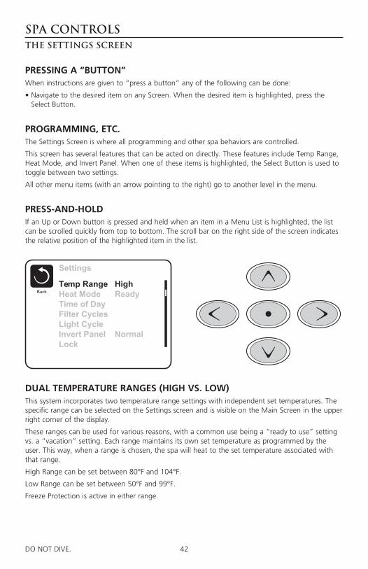
42DO NOT DIVE.
SPA CONTROLSThe Settings Screen
Settings
BackTemp RangeHeat ModeTime of DayFilter CyclesLight CycleInvert PanelLock
HighReady
Normal
PRESSING A “BUTTON”When instructions are given to “press a button” any of the following can be done:
• Navigate to the desired item on any Screen. When the desired item is highlighted, press the Select Button.
PROGRAMMING, ETC. The Settings Screen is where all programming and other spa behaviors are controlled.
This screen has several features that can be acted on directly. These features include Temp Range, Heat Mode, and Invert Panel. When one of these items is highlighted, the Select Button is used to toggle between two settings.
All other menu items (with an arrow pointing to the right) go to another level in the menu.
PRESS-AND-HOLDIf an Up or Down button is pressed and held when an item in a Menu List is highlighted, the list can be scrolled quickly from top to bottom. The scroll bar on the right side of the screen indicates the relative position of the highlighted item in the list.
DUAL TEMPERATURE RANGES (HIGH VS. LOW)This system incorporates two temperature range settings with independent set temperatures. The specific range can be selected on the Settings screen and is visible on the Main Screen in the upper right corner of the display.
These ranges can be used for various reasons, with a common use being a “ready to use” setting vs. a “vacation” setting. Each range maintains its own set temperature as programmed by the user. This way, when a range is chosen, the spa will heat to the set temperature associated with that range.
High Range can be set between 80°F and 104°F.
Low Range can be set between 50°F and 99°F.
Freeze Protection is active in either range.
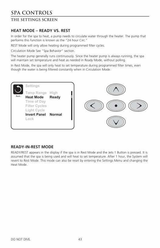
43DO NOT DIVE.
SPA CONTROLSThe Settings Screen
Settings
BackTemp RangeHeat ModeTime of DayFilter CyclesLight CycleInvert PanelLock
HighReady
Normal
HEAT MODE – READY VS. RESTIn order for the spa to heat, a pump needs to circulate water through the heater. The pump that performs this function is known as the “24 hour Circ.”
REST Mode will only allow heating during programmed filter cycles.
Circulation Mode See “Spa Behavior” section.
The heater pump generally runs continuously. Since the heater pump is always running, the spa will maintain set temperature and heat as needed in Ready Mode, without polling.
In Rest Mode, the spa will only heat to set temperature during programmed filter times, even though the water is being filtered constantly when in Circulation Mode.
READY-IN-REST MODEREADY/REST appears in the display if the spa is in Rest Mode and the Jets 1 Button is pressed. It is assumed that the spa is being used and will heat to set temperature. After 1 hour, the System will revert to Rest Mode. This mode can also be reset by entering the Settings Menu and changing the Heat Mode.

44DO NOT DIVE.
SPA CONTROLSInitial Start-Up
PREPARATION AND FILLINGFill the spa to its correct operating level. Be sure to open all valves and jets in the plumbing system before filling to allow as much air as possible to escape from the plumbing and the control system during the filling process.
After turning the power on at the main power panel, the top-side panel will display a splash, or startup screen.
PRIMING MODEAfter the initial start-up sequence, the control will enter Priming Mode and display a Priming Mode screen. Only pump icons appear on the priming mode screen. The system will automatical-ly return to normal heating and filtering at the end of the priming mode, which lasts 4-5 minutes. During the priming mode, the heater is disabled to allow the priming process to be completed without the possibility of energizing the heater under low-flow or no-flow conditions. Nothing comes on automatically, but the
pump(s) can be energized by selecting the “Jet” buttons. The 24 hour Circ Pump can be activated by pressing the dedicated “Light” button during Priming Mode.
Manually exit Priming Mode by pressing the “Exit” Button.
PRIMING THE PUMPSAs soon as the Priming Mode screen appears on the panel, select the “Jets 1” button once to start Pump 1 in low-speed and then again to switch to high-speed. Also, select the other pumps, to turn them on. The pumps should be running in high-speed to facilitate priming. If the pumps have not primed after 2 minutes, and water is not flowing from the jets in the spa, do not allow the pumps to continue to run. Turn off the pumps and repeat the process. Note: Turning the power off and back on again will initiate a new pump priming session. Sometimes momentarily turning the pump off and on will help it to prime. Do not do this more than 5 times. If the pump(s) will not prime, the pump(s) will need relieved of an air lock. See Installation Instructions for information on bleed-ing air from a pump to relieve an air lock. If you need further assistance, your spa dealer can be contacted. Regular maintenance procedures would not be covered under the spa warranty.
Important: A pump should not be allowed to run without priming for more than 2 minutes. Under NO circumstances should a pump be allowed to run without priming beyond the end of the 4-5 minute priming mode. Doing so may cause damage to the pump and cause the system to energize the heater and go into an overheat condition.
EXITING PRIMING MODEYou can manually exit Priming Mode by navigating to the “Back” button on the Priming Mode Screen. Note that if you do not manually exit the priming mode as described above, the prim-ing mode will be automatically terminated after 4-5 minutes. Be sure that the pump(s) have been primed by this time.
Once the system has exited Priming Mode, the top-side panel will display the Main Screen, but the display will not show the temperature yet, as shown below. This is because the system requires approximately 1 minute of water flowing through the heater to determine the water temperature and display it.
Priming Mode
Jets 2 Jets 3 CircJets 1Exit
– – –°F– – –°C

45DO NOT DIVE.
SPA CONTROLSSpa Behavior
PUMPSOn the Spa Screen, select a “Jets” button once to turn the pump on or off, and to shift between low- and high-speeds if equipped. If left running, the pump will turn off after a time-out period. The pump 1 low-speed will time out after 30 minutes. The high-speed will time-out after 15 min-utes.
CIRCULATION PUMP MODESThe 24 hour circ pump operates continuously with the exception of turning off for 30 minutes at a time when the water temperature reaches 3°F (1.5°C) above the set temperature (most likely to happen in very hot climates).
FILTRATION AND OZONEThe system is factory-programmed with one filter cycle that will run in the evening (assuming the time-of-day is properly set) when energy rates are often lower. The filter time and duration are programmable. See Adjusting Filtration” section. A second filter cycle can be enabled as needed.
At the start of each filter cycle, the pumps will run briefly to purge the plumbing to maintain good water quality. On spas equipped with 24 hour circulation systems the filter cycles cannot be set. (See adjusting filtration section).
FREEZE PROTECTIONIf the temperature sensors within the heater detect a low enough temperature, then the pumps automatically activate to provide freeze protection. The pumps will run either continuously or peri-odically depending on conditions. If the temperature sensors detect a drop to below 44°F/6.7°C within the heater, the pump will automatically activate to provide freeze protection. The equip-ment stays on until 4 minutes after the sensors detect that the spa temperature has risen to 45°F/7.2°C or higher.
CLEAN-UP CYCLEWhen a pump is turned on by a button press, a clean-up cycle begins 30 minutes after the pump is turned off or times out. The pump and the ozone generator will run for 30 minutes or more, depending on the system. This setting can be changed. See “Preferences” section.
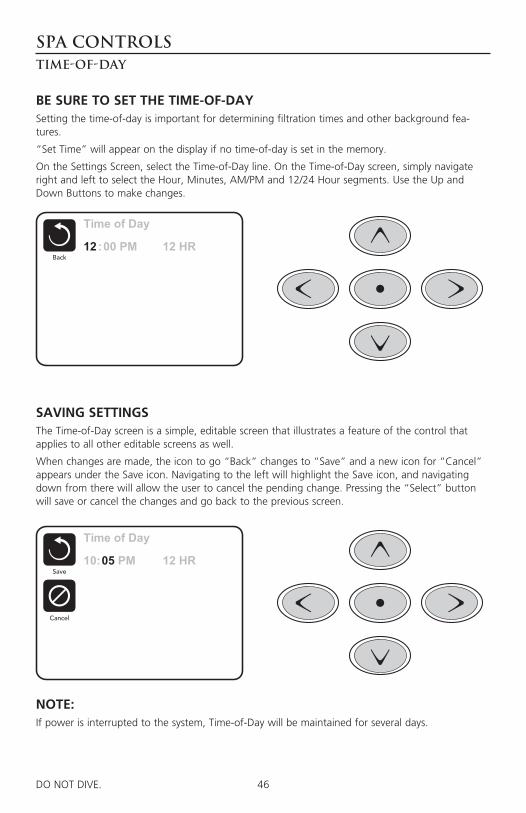
46DO NOT DIVE.
SPA CONTROLSTime-of-Day
Time of Day
Back12 :00 PM 12 HR
Cancel
Save10:05 PM 12 HR
Time of Day
Back12 :00 PM 12 HR
BE SURE TO SET THE TIME-OF-DAYSetting the time-of-day is important for determining filtration times and other background fea-tures.
“Set Time” will appear on the display if no time-of-day is set in the memory.
On the Settings Screen, select the Time-of-Day line. On the Time-of-Day screen, simply navigate right and left to select the Hour, Minutes, AM/PM and 12/24 Hour segments. Use the Up and Down Buttons to make changes.
SAVING SETTINGSThe Time-of-Day screen is a simple, editable screen that illustrates a feature of the control that applies to all other editable screens as well.
When changes are made, the icon to go “Back” changes to “Save” and a new icon for “Cancel” appears under the Save icon. Navigating to the left will highlight the Save icon, and navigating down from there will allow the user to cancel the pending change. Pressing the “Select” button will save or cancel the changes and go back to the previous screen.
NOTE:If power is interrupted to the system, Time-of-Day will be maintained for several days.
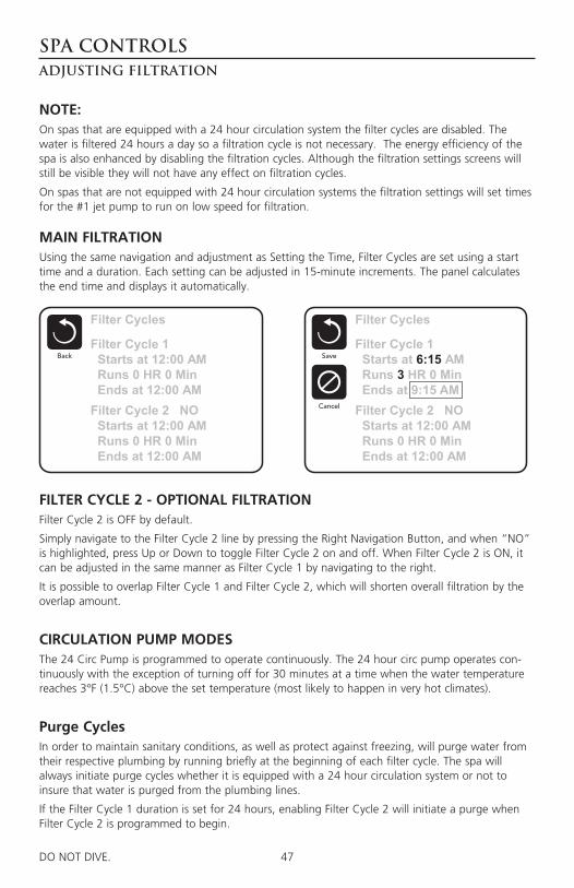
47DO NOT DIVE.
SPA CONTROLSAdjusting Filtration
NOTE:On spas that are equipped with a 24 hour circulation system the filter cycles are disabled. The water is filtered 24 hours a day so a filtration cycle is not necessary. The energy efficiency of the spa is also enhanced by disabling the filtration cycles. Although the filtration settings screens will still be visible they will not have any effect on filtration cycles.
On spas that are not equipped with 24 hour circulation systems the filtration settings will set times for the #1 jet pump to run on low speed for filtration.
Filter Cycles
BackFilter Cycle 1 Starts at 12:00 AM Runs 0 HR 0 Min Ends at 12:00 AMFilter Cycle 2 NO Starts at 12:00 AM Runs 0 HR 0 Min Ends at 12:00 AM
Filter Cycles
BackFilter Cycle 1 Starts at 6:15 AM Runs 3 HR 0 Min Ends at 9:15 AMFilter Cycle 2 NO Starts at 12:00 AM Runs 0 HR 0 Min Ends at 12:00 AM
Cancel
Save
MAIN FILTRATIONUsing the same navigation and adjustment as Setting the Time, Filter Cycles are set using a start time and a duration. Each setting can be adjusted in 15-minute increments. The panel calculates the end time and displays it automatically.
FILTER CYCLE 2 - OPTIONAL FILTRATIONFilter Cycle 2 is OFF by default.
Simply navigate to the Filter Cycle 2 line by pressing the Right Navigation Button, and when “NO” is highlighted, press Up or Down to toggle Filter Cycle 2 on and off. When Filter Cycle 2 is ON, it can be adjusted in the same manner as Filter Cycle 1 by navigating to the right.
It is possible to overlap Filter Cycle 1 and Filter Cycle 2, which will shorten overall filtration by the overlap amount.
CIRCULATION PUMP MODESThe 24 Circ Pump is programmed to operate continuously. The 24 hour circ pump operates con-tinuously with the exception of turning off for 30 minutes at a time when the water temperature reaches 3°F (1.5°C) above the set temperature (most likely to happen in very hot climates).
Purge CyclesIn order to maintain sanitary conditions, as well as protect against freezing, will purge water from their respective plumbing by running briefly at the beginning of each filter cycle. The spa will always initiate purge cycles whether it is equipped with a 24 hour circulation system or not to insure that water is purged from the plumbing lines.
If the Filter Cycle 1 duration is set for 24 hours, enabling Filter Cycle 2 will initiate a purge when Filter Cycle 2 is programmed to begin.
48DO NOT DIVE.
SPA CONTROLSAdditional Settings
Dedicated Buttons
INVERT PANELSelecting Invert Panel will flip the display and the buttons so the panel can be easily operated from inside or outside the hot tub.
SPECIFIC BUTTONS FOR SPECIFIC DEVICESThe panel has dedicated function buttons installed, pressing those buttons will activate the device indicated for that button.
These dedicated buttons will operate just like the Spa Screen buttons and the equipment will behave in the same manner with each button press.
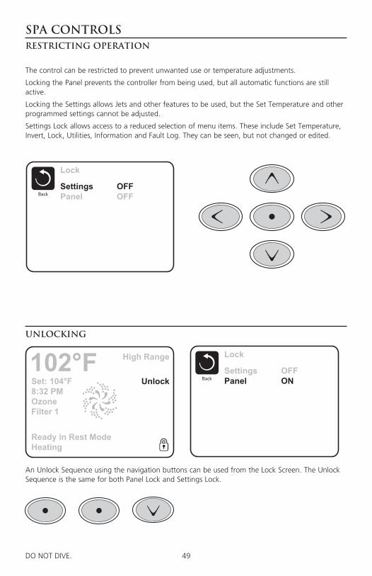
49DO NOT DIVE.
SPA CONTROLSRestricting Operation
Lock
BackSettingsPanel
OFFONSet: 104°F
8:32 PMOzoneFilter 1
Unlock
High Range102°F
Ready in Rest ModeHeating
Lock
BackSettingsPanel
OFFOFF
The control can be restricted to prevent unwanted use or temperature adjustments.
Locking the Panel prevents the controller from being used, but all automatic functions are still active.
Locking the Settings allows Jets and other features to be used, but the Set Temperature and other programmed settings cannot be adjusted.
Settings Lock allows access to a reduced selection of menu items. These include Set Temperature, Invert, Lock, Utilities, Information and Fault Log. They can be seen, but not changed or edited.
An Unlock Sequence using the navigation buttons can be used from the Lock Screen. The Unlock Sequence is the same for both Panel Lock and Settings Lock.
Unlocking

50DO NOT DIVE.
SPA CONTROLSAdditional Settings
Fault Log
BackEntry 2 Message Code M026 1 Days Ago 2:21PM Rest Mode High Range Set Temp 104°F Sensors: A: 100 B: 96
Message:Sensors are out of sync
HOLD MODEHold Mode is used to disable the pumps during service functions like cleaning or replacing the filter. Hold Mode will last for 1 hour unless the mode is exited manually. If spa service will require more than an hour, it may be best to simply shut down power to the spa.
Utilities The Utilities Menu contains the following:
A/B Temps When this is set to On, the temperature display will alternate to display temperature from Sensor A and Sensor B in the heater.
Fault Log The Fault Log is a record of the last 24 faults that can be reviewed by a service tech.

51DO NOT DIVE.
SPA CONTROLSAdditional Settings
Preferences
BackTemp DisplayTime DisplayRemindersCleanupDolphinColorLanguage
°F12 HROn0.5 HR 5 BlueEnglish
PREFERENCES The Preferences Menu allows the user to change certain parameters based on personal preference.
Temp Display Change the temperature between Fahrenheit and Celsius.
Time Display Change the clock between 12 hr and 24 hr display.
Cleanup Cleanup Cycle Duration default is 30 minutes. The duration can be set in 30 minute increments for up to 4 hours. 30 minutes after any of the jet pumps have been activated, the #1 jet pump will run low speed for the set cleanup cycle duration. If the #1 jet pump does not have low speed, this may not apply.
Color Pressing the Select Button when Color is highlighted will cycle through 5 background colors avail-able in the control.
Language Change the language displayed on the panel.

52DO NOT DIVE.
SPA CONTROLSInformation
System Information
BackSoftware ID (SSID)System ModelCurrent SetupConfiguration SignatureHeater VoltageHeater Type
Software ID (SSID):M100_101 V0.6
SYSTEM INFORMATION The System Information Menu displays various settings and identification of the particular system. As each item in the menu is highlighted, the detail for that item is displayed at the bottom of the screen. These settings are for information only and cannot be changed.
Software ID (SSID) Displays the software ID number for the System.
System Model Displays the Model Number of the System.
Current Setup Displays the currently selected Configuration Setup Number.
Configuration Signature Displays the checksum for the system configuration file.
Heater Voltage (Feature not used on CE rated systems.) Displays the operating voltage configured for the heater.
Heater Wattage as Configured in Software (CE Systems Only.)Displays a heater kilowatt rating as programmed into the control system software (1-3 or 3-6).
Heater Type Displays a heater type ID number.
Dip Switch Settings Displays a number that represents the DIP switch positions of S1 on the main circuit board.
Panel Version Displays a number of the software in the topside control panel.
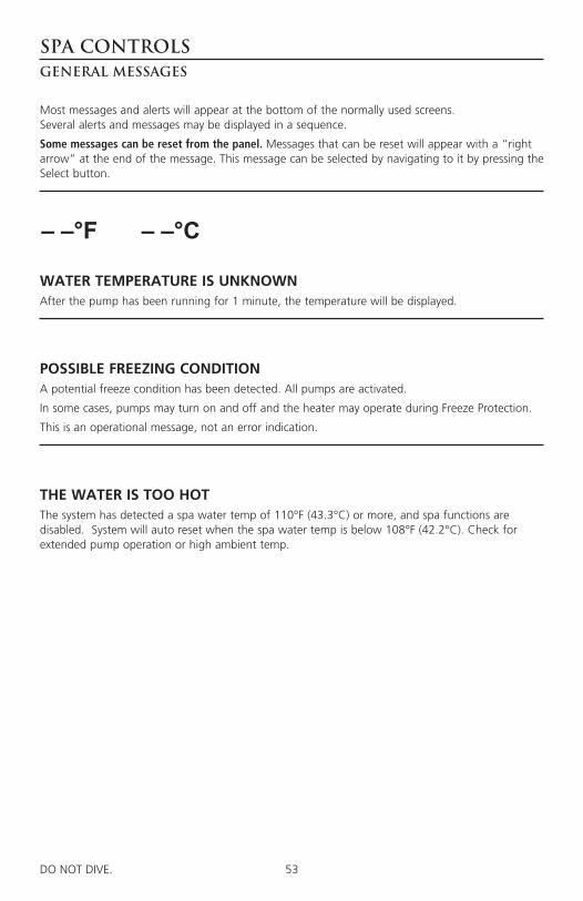
53DO NOT DIVE.
SPA CONTROLSGeneral Messages
Most messages and alerts will appear at the bottom of the normally used screens. Several alerts and messages may be displayed in a sequence.
Some messages can be reset from the panel. Messages that can be reset will appear with a “right arrow” at the end of the message. This message can be selected by navigating to it by pressing the Select button.
WATER TEMPERATURE IS UNKNOWNAfter the pump has been running for 1 minute, the temperature will be displayed.
POSSIBLE FREEZING CONDITIONA potential freeze condition has been detected. All pumps are activated.
In some cases, pumps may turn on and off and the heater may operate during Freeze Protection.
This is an operational message, not an error indication.
THE WATER IS TOO HOTThe system has detected a spa water temp of 110°F (43.3°C) or more, and spa functions are disabled. System will auto reset when the spa water temp is below 108°F (42.2°C). Check for extended pump operation or high ambient temp.
– – –°F– – –°C

54DO NOT DIVE.
SPA CONTROLSHeater-Related Messages
THE WATER FLOW IS LOWThere may not be enough water flow through the heater to carry the heat away from the heating element. Heater start up will begin again after about 1 min. See “Flow Related Checks” below.
THE WATER FLOW HAS FAILED*There is not enough water flow through the heater to carry the heat away from the heating ele-ment and the heater has been disabled. See “Flow Related Checks” below. After the problem has been resolved, you must press any button to reset and begin heater start up.
THE HEATER MAY BE DRY*Possible dry heater, or not enough water in the heater to start it. The spa is shut down for 15 min. Press any button to reset the heater start-up. See “Flow Related Checks” below.
THE HEATER IS DRY*There is not enough water in the heater to start it. The spa is shut down. After the problem has been resolved, you must clear the message to restart heater start up. See “Flow Related Checks” below.
THE HEATER IS TOO HOT*One of the water temp sensors has detected 118°f (47.8°C) in the heater and the spa is shut down. You must clear the message when water is below 108°f (42.2°C). See “Flow Related Checks” below.
FLOW-RELATED CHECKSCheck filters for possible blockage. Try cleaning or replacing filters (especially if spa is equipped with 24 hour circulation pump).
Check for low water level, clogged filters, suction flow restrictions, closed valves, trapped air, too many closed jets and pump prime.
On some systems, even when spa is shut down by an error condition, some equipment may occa-sionally turn on to continue monitoring temperature or if freeze protection is needed.
* This message can be reset from the topside panel.
55DO NOT DIVE.
SPA CONTROLSSensor-Related Messages
Miscellaneous Messages
SENSORS ARE OUT OF SYNCThe temperature sensors MAY be out of sync by 2°F or 3°F. Call for Service.
SENSORS ARE OUT OF SYNC -- CALL FOR SERVICE*The temperature sensors ARE out of sync. The fault above has been established for at least 1 hour. Call for Service.
SENSOR A FAULT, SENOR B FAULTA temperature sensor or sensor circuit has failed. Call for Service.
COMMUNICATIONS ERRORThe control panel is not receiving communication from the System. Call for Service.
TEST SOFTWARE INSTALLEDThe Control System is operating with test software. Call for Service.
°F OR °C IS REPLACED BY °TThe Control System is in Test Mode. Call for Service.
* This message can be reset from the topside panel.

56DO NOT DIVE.
SPA CONTROLSSystem-Related Messages
PROGRAM MEMORY FAILURE*At Power-Up, the system has failed the Program Checksum Test. This indicates a problem with the firmware (operation program) and requires a service call.
THE SETTINGS HAVE BEEN RESET (PERSISTENT MEMORY ERROR)*Contact your dealer or service organization if this message appears on more than one power-up.
THE CLOCK HAS FAILED* Contact your dealer or service organization.
CONFIGURATION ERROR (SPA WILL NOT START UP)Contact your dealer or service organization.
A PUMP MAY BE STUCK ONWater may be overheated. POWER DOWN THE SPA. DO NOT ENTER THE WATER. Contact your dealer or service organization.
HOT FAULTA Pump Appears to have been Stuck ON when spa was last powered
POWER DOWN THE SPA. DO NOT ENTER THE WATER. Contact your dealer or service organization.
* This message can be reset from the topside panel.
57DO NOT DIVE. 100DO NOT DIVE.
Wi-Fi Module (if equipped)
Remotely control the operations of your spa via an optional integrated Wi-Fi module that works with the Balboa Water Group Wi-Fi Spa Control App. This app is available for Apple® or Android® devices. Please refer to the Balboa Water Group website and mobile device app for operation information.
http://www.balboawater.com/bwa
Note: WiFi Module is not available for all spa models. If this options was not added from the factory, see your Master Spas dealer for further details and compatibility.
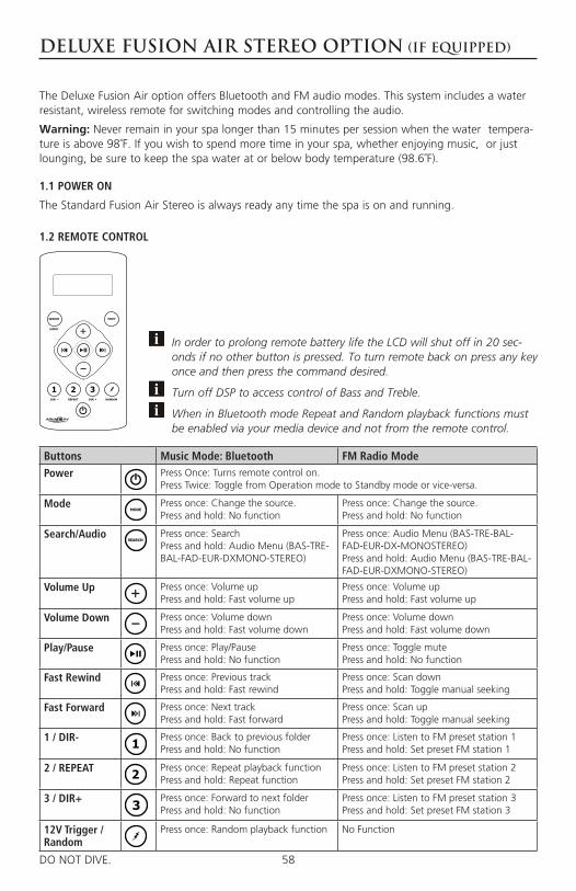
58DO NOT DIVE. 100DO NOT DIVE.
Deluxe Fusion Air Stereo Option (if equipped)
The Deluxe Fusion Air option offers Bluetooth and FM audio modes. This system includes a water resistant, wireless remote for switching modes and controlling the audio.
Warning: Never remain in your spa longer than 15 minutes per session when the water tempera-ture is above 98˚F. If you wish to spend more time in your spa, whether enjoying music, or just lounging, be sure to keep the spa water at or below body temperature (98.6˚F).
1.1 POWER ON
The Standard Fusion Air Stereo is always ready any time the spa is on and running.
Buttons Music Mode: Bluetooth FM Radio ModePower Press Once: Turns remote control on.
Press Twice: Toggle from Operation mode to Standby mode or vice-versa.
Mode Press once: Change the source.Press and hold: No function
Press once: Change the source.Press and hold: No function
Search/Audio Press once: SearchPress and hold: Audio Menu (BAS-TRE-BAL-FAD-EUR-DXMONO-STEREO)
Press once: Audio Menu (BAS-TRE-BAL-FAD-EUR-DX-MONOSTEREO)Press and hold: Audio Menu (BAS-TRE-BAL-FAD-EUR-DXMONO-STEREO)
Volume Up Press once: Volume upPress and hold: Fast volume up
Press once: Volume upPress and hold: Fast volume up
Volume Down Press once: Volume downPress and hold: Fast volume down
Press once: Volume downPress and hold: Fast volume down
Play/Pause Press once: Play/PausePress and hold: No function
Press once: Toggle mutePress and hold: No function
Fast Rewind Press once: Previous trackPress and hold: Fast rewind
Press once: Scan downPress and hold: Toggle manual seeking
Fast Forward Press once: Next trackPress and hold: Fast forward
Press once: Scan upPress and hold: Toggle manual seeking
1 / DIR- Press once: Back to previous folderPress and hold: No function
Press once: Listen to FM preset station 1Press and hold: Set preset FM station 1
2 / REPEAT Press once: Repeat playback functionPress and hold: Repeat function
Press once: Listen to FM preset station 2Press and hold: Set preset FM station 2
3 / DIR+ Press once: Forward to next folderPress and hold: No function
Press once: Listen to FM preset station 3Press and hold: Set preset FM station 3
12V Trigger /Random
Press once: Random playback function No Function
In order to prolong remote battery life the LCD will shut off in 20 sec-onds if no other button is pressed. To turn remote back on press any key once and then press the command desired.
Turn off DSP to access control of Bass and Treble.
When in Bluetooth mode Repeat and Random playback functions must be enabled via your media device and not from the remote control.
1.2 REMOTE CONTROL
59DO NOT DIVE. 101DO NOT DIVE.
Deluxe Fusion Air Stereo Option
1.3 HANDHELD REMOTE CONTROL BATTERY INSTALL
Unscrew the waterproof cap on the back of the remote control. Place the CR-2450 battery in the RF remote control and replace the water/dust proof cap. When the battery is installed, the remote control LCD should be solid and bright without any flickering.
1.4 HANDHELD REMOTE CONTROL SYNCHRONIZING
The remote should already be paired from the factory, but if you need to re synchronize the remote follow the steps below.
1. Press the POWER button on the remote control to turn on the remote.
2. The LCD will become illuminated and read ‘NO LINK’.
3. Press and hold the MODE button for 5 – 10 seconds.
4. Once the remote has been paired, the LCD will display one of the audio modes (BT AUDIO or AUX).
For any additional remote controls, you will also need to activate/synchronize those remote controls by following the steps above.
If the pairing process is not effective, check the battery voltage of the remote. If above 3V DC refer to section 1.5 above top make sure the battery is installed correctly. If battery voltage is below 3V DC replace the battery.
If the LCD displays “NO LINK” in any mode, this means the remote is out of reception range or not paired correctly. Move the remote closer to the unit and try again.
If you lose your remote control and buy a new remote control, please follow the above to pair remote control.
2.1 PAIR WITH BLUETOOTH DEVICE
1. Switch on your Bluetooth device.
2. Select ‘AQUATIC AV’ from the list of available devices to pair (no password is needed).
Only one Bluetooth device can be paired with the BlueCube Media Player at any time.
2.2 LISTENING VIA BLUETOOTH DEVICE
1. Bluetooth mode will be activated once a Bluetooth device is paired.
2. Play the song from device and the sound will play through the BlueCube Media Player.
3. Press (PLAY/PAUSE) to play/pause the song.
4. Press / (FAST REWIND/FORWARD) buttons to play previous/next song file.
5. Track and volume can be controlled directly from your Bluetooth device or remote control.
60DO NOT DIVE. 102DO NOT DIVE.
Deluxe Fusion Air Stereo Option
3.1 LISTENING VIA FM
1. Press (MODE) on remote control to switch to FM radio mode.
If this is the first time you listen to FM radio, the default frequency will be 87.5MHz, as shown on the remote LCD.
FM radio is only available when you are in the FM Radio mode.
3.2 SCAN OR SEEK FM RADIO CHANNELS
1. Press (FAST REWIND) or (FAST FORWARD) to seek another station.
2. Press and hold either (FAST REWIND) or (FAST FORWARD) for manual tuning back or forward.
After using Seek mode the unit will automatically switch back into Scan mode after 20 seconds.
3.3 SAVING RADIO CHANNEL TO MEMORY
To save the current frequency into memory, press and hold , or for more than 2 sec-onds. The station will be stored into relevant button.
3.4 LISTENING TO SAVED RADIO MEMORY
Press the , or preset button once to listen to the station stored in that button.
3.5 SWITCH BETWEEN US AND EUROPEAN FM MODES
1. Make sure dock and remote are turned on and in ‘RADIO’ mode.
2. Press the AUDIO button 6 time in a row.
3. The remote will display ‘AREA USA’ or ‘AREA EUR’ depending on which tuning mode is cur-rently selected.
4. Use the and buttons to switch between US or European modes.
5. Press PLAY/PAUSE) to select the desired tuning mode.
6. Once you switch modes it will default to the FM station stored in ‘PRESET’.
US mode will increase and decrease the FM frequency in steps of 0.1 MHz, e.g. 88.5, 88.6,88.7 MHz. EUR mode will increase and decrease the FM frequency in steps of 0.05 MHz, e.g. 88.25, 88.30, 88.35 MHz.
When in Seek mode and European FM tuning mode, all frequency steps will be visible.
4.1 ADJUST VOLUME LEVEL
1. Press (VOLUME UP) once to increase the volume.
2. Press (VOLUME DOWN) once to reduce the volume.
3. Press and hold either or and the BlueCube Media Player will increase or decrease audio volume continuously.
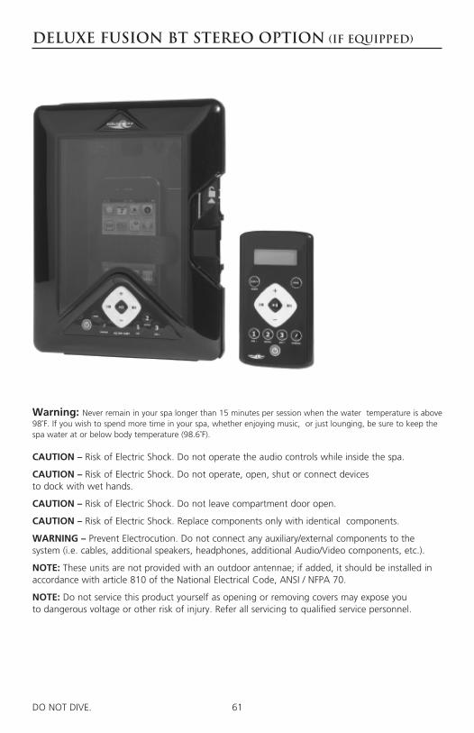
61DO NOT DIVE. 100DO NOT DIVE.
Deluxe Fusion BT Stereo Option (if equipped)
Warning: Never remain in your spa longer than 15 minutes per session when the water temperature is above 98˚F. If you wish to spend more time in your spa, whether enjoying music, or just lounging, be sure to keep the spa water at or below body temperature (98.6˚F).
CAUTION – Risk of Electric Shock. Do not operate the audio controls while inside the spa.
CAUTION – Risk of Electric Shock. Do not operate, open, shut or connect devices to dock with wet hands.
CAUTION – Risk of Electric Shock. Do not leave compartment door open.
CAUTION – Risk of Electric Shock. Replace components only with identical components.
WARNING – Prevent Electrocution. Do not connect any auxiliary/external components to the system (i.e. cables, additional speakers, headphones, additional Audio/Video components, etc.).
NOTE: These units are not provided with an outdoor antennae; if added, it should be installed in accordance with article 810 of the National Electrical Code, ANSI / NFPA 70.
NOTE: Do not service this product yourself as opening or removing covers may expose you to dangerous voltage or other risk of injury. Refer all servicing to qualified service personnel.
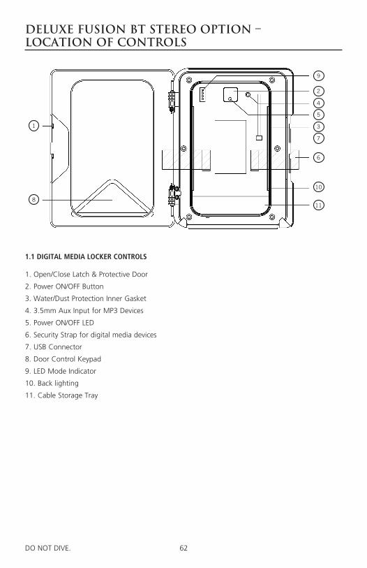
62DO NOT DIVE. 101DO NOT DIVE.
Deluxe Fusion BT Stereo Option – Location of Controls
1.1 DIGITAL MEDIA LOCKER CONTROLS
1. Open/Close Latch & Protective Door
2. Power ON/OFF Button
3. Water/Dust Protection Inner Gasket
4. 3.5mm Aux Input for MP3 Devices
5. Power ON/OFF LED
6. Security Strap for digital media devices
7. USB Connector
8. Door Control Keypad
9. LED Mode Indicator
10. Back lighting
11. Cable Storage Tray
2
9
11
10
6
7
3
5
4
8
1

63DO NOT DIVE. 102DO NOT DIVE.
Deluxe Fusion BT Stereo Option – Location of Controls
Buttons Music Mode: iPhone, iPod, Bluetooth, USB & MP3
FM Radio Mode
Power Press once: Toggle from Operation mode to Standby mode or vice-versa.
Mode Press once: Change the source.Press and hold: No function
Press once: Change the source.Press and hold: No function
Volume Up Press once: Volume upPress and hold: Fast volume up
Press once: Volume upPress and hold: Fast volume up
Volume Down Press once: Volume downPress and hold: Fast volume down
Press once: Volume downPress and hold: Fast volume down
Fast Rewind Press once: Previous trackPress and hold: Fast rewind
Press once: Scan downPress and hold: Toggle manual seeking
Fast Forward Press once: Next trackPress and hold: Fast forward
Press once: Scan upPress and hold: Toggle to manual seeking
12V Trigger / Random
Press once: Random playbackPress and hold: Toggle 12V on/off
Press once: No functionPress and hold: Toggle external 12V power on/off
Play/pause Press once: Play/PausePress and hold: No function
Press once: Toggle mutePress and hold: No function
1 / DIR- Press once: Back to previous folderPress and hold: No function
Press once: Listen to FM preset station 1Press and hold: Set preset FM station 1
2 / REPEAT Press once: Repeat functionPress and hold: No function
Press once: Listen to FM preset station 2Press and hold: Set preset FM station 2
3 / DIR+ Press once: Forward to next folderPress and hold: No function
Press once: Listen to FM preset station 3Press and hold: Set preset FM station 3
The keypad on the door has a set of keys fewer than those on the remote but has exactly the same functions correspondingly. This keypad allows you to operate the dock without the remote control.
1.2 DOOR KEYPAD CONTROLS
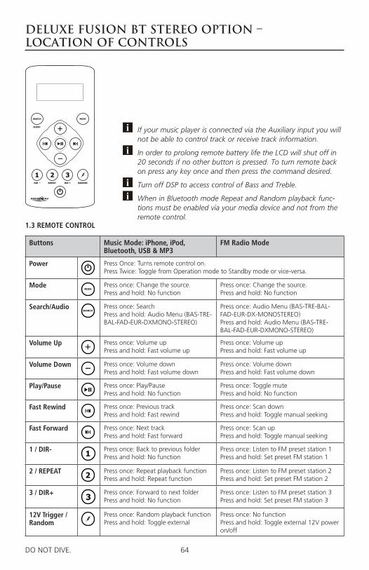
64DO NOT DIVE. 103DO NOT DIVE.
Deluxe Fusion BT Stereo Option – Location of Controls
Buttons Music Mode: iPhone, iPod, Bluetooth, USB & MP3
FM Radio Mode
Power Press Once: Turns remote control on.Press Twice: Toggle from Operation mode to Standby mode or vice-versa.
Mode Press once: Change the source.Press and hold: No function
Press once: Change the source.Press and hold: No function
Search/Audio Press once: SearchPress and hold: Audio Menu (BAS-TRE-BAL-FAD-EUR-DXMONO-STEREO)
Press once: Audio Menu (BAS-TRE-BAL-FAD-EUR-DX-MONOSTEREO)Press and hold: Audio Menu (BAS-TRE-BAL-FAD-EUR-DXMONO-STEREO)
Volume Up Press once: Volume upPress and hold: Fast volume up
Press once: Volume upPress and hold: Fast volume up
Volume Down Press once: Volume downPress and hold: Fast volume down
Press once: Volume downPress and hold: Fast volume down
Play/Pause Press once: Play/PausePress and hold: No function
Press once: Toggle mutePress and hold: No function
Fast Rewind Press once: Previous trackPress and hold: Fast rewind
Press once: Scan downPress and hold: Toggle manual seeking
Fast Forward Press once: Next trackPress and hold: Fast forward
Press once: Scan upPress and hold: Toggle manual seeking
1 / DIR- Press once: Back to previous folderPress and hold: No function
Press once: Listen to FM preset station 1Press and hold: Set preset FM station 1
2 / REPEAT Press once: Repeat playback functionPress and hold: Repeat function
Press once: Listen to FM preset station 2Press and hold: Set preset FM station 2
3 / DIR+ Press once: Forward to next folderPress and hold: No function
Press once: Listen to FM preset station 3Press and hold: Set preset FM station 3
12V Trigger /Random
Press once: Random playback functionPress and hold: Toggle external
Press once: No functionPress and hold: Toggle external 12V power on/off
If your music player is connected via the Auxiliary input you will not be able to control track or receive track information.
In order to prolong remote battery life the LCD will shut off in 20 seconds if no other button is pressed. To turn remote back on press any key once and then press the command desired.
Turn off DSP to access control of Bass and Treble.
When in Bluetooth mode Repeat and Random playback func-tions must be enabled via your media device and not from the remote control.
1.3 REMOTE CONTROL
65DO NOT DIVE. 104DO NOT DIVE.
Deluxe Fusion BT Stereo Option – Getting started
2.1 REMOTE CONTROL BATTERY INSTALL
Remove the RF wireless remote control from the Digital Media Locker box. Unscrew the waterproof cap on the back of the remote control. Place the CR-2450 battery in the RF remote control and replace the water/dust proof cap.
When the battery is installed, the remote control LCD should be solid and bright without any flick-ering.
2.2 POWER ON
Press the on/off button.
Red Light: Power to the docking station is ON, but the unit is in standby mode. Blue Light: The unit is powered ON and looking for an audio source.
For applications that require low current draw and where battery drain may occur, the power but-ton must be turned OFF inside the unit. When the power button is in the OFF position the red LED will not be lit.
For applications where a 12V battery is not used, such as in a Spa, the power button can be left ON and the remote control or door controls can then be used to power on/off accordingly.
2.3 REMOTE CONTROL SYNCHRONIZING
1. Turn the Digital Media Locker to off mode with the power button inside the door. The LED should not be illuminated.
2. Press the red (POWER) button on the remote.
3. Press and hold the (MODE) button until the LCD reads PAIR.
4. Continue to press and hold the (MODE) button during step 5 below.
5. Turn the docking station to standby mode (within 10 seconds) with the on/off button inside door (the red LED will illuminate and then turn blue).
6. The remote’s LCD should read WELCOME or show a mode position such as RADIO, USB, BT or AUX IN.
For any additional remote controls, you will also need to activate/synchronize those remote controls by following the steps above.
If the pairing process is not effective, switch the locker off using the on/off button located inside the door of the dock. Unplug the 12-pin Harness on the back of the Locker for 3 min-utes. Reattach the Harness and repeat steps 1-6 above.
If the pairing process is not effective, check the battery voltage. If above 3V DC refer to sec-tion 1.5 above top make sure the battery is installed correctly. If battery voltage is below 3V DC replace the battery.
If the LCD displays “NO LINK” in either mode, this means the remote is out of reception range. Move the remote closer to the Locker and try again.
If you lose your remote control and buy another new remote control, please follow the above to start pairing before normal usage.

66DO NOT DIVE. 105DO NOT DIVE.
Deluxe Fusion BT Stereo Option – Listening to Devices
3.1 LISTENING VIA USB
1. Power up the Digital Media Locker
2. Attach your device to the USB cable inside the Digital Media Locker using the appropriate USB adaptor.
3. Secure the device with the anchor straps provided.
4. Secure the Digital Media Locker’s protective door.
5. Press (POWER) on the remote control or Power button on the locker to turn it ON.
6. Press (MODE) on the remote control to select USB mode. Use the buttons as shown in the remote function chart.
Always ensure to connect and disconnect your media player with dry hands!
3.1.1.1 USB SEARCH
1. When using a USB device, press (SEARCH) to enter the USB searching mode.
2. Use and (Volume UP/DOWN) to scroll through the folders on your USB device and to select a folder press the (PLAY/PAUSE) button.
3. Use and (Volume UP/DOWN) to scroll through the songs in the folder and press (PLAY/PAUSE) to play the desired song.
3.1.1.2 IPHONE & IPOD SEARCH
1. When using an iPhone or iPod, press (SEARCH) to enter iPod searching mode.
2. Once in searching mode the remote will display ‘Playlist’. Continue to press (SEARCH) to scroll through the search modes below:
1) Playlist 2) Artist 3) Album 4) Song 5) Genre 6) Composer 7) Audio Book
3. Press (PLAY/PAUSE) To select the desired search mode.
4. Use and (Volume UP/DOWN) to scroll through your media in the selected search mode.
5. Once you find the desired media press (PLAY/PAUSE) to make your selection. If your section is a song it will begin to play, if you select a playlist, artist, album, genre, composer or audio book, the songs in the selected folder will be visible. Press (PLAY/PAUSE) to play the desired song within the folder.
3.1.2 DEVICE CHARGING
When specified USB devices are connected to the USB input the device battery will charge.
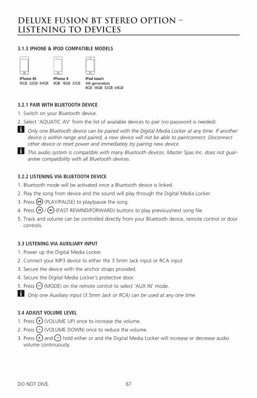
67DO NOT DIVE. 106DO NOT DIVE.
Deluxe Fusion BT Stereo Option – Listening to Devices
3.1.3 IPHONE & IPOD COMPATIBLE MODELS
3.2.1 PAIR WITH BLUETOOTH DEVICE
1. Switch on your Bluetooth device.
2. Select ‘AQUATIC AV’ from the list of available devices to pair (no password is needed).
Only one Bluetooth device can be paired with the Digital Media Locker at any time. If another device is within range and paired, a new device will not be able to pair/connect. Disconnect other device or reset power and immediately try pairing new device.
This audio system is compatible with many Bluetooth devices. Master Spas Inc. does not guar-antee compatibility with all Bluetooth devices.
3.2.2 LISTENING VIA BLUETOOTH DEVICE
1. Bluetooth mode will be activated once a Bluetooth device is linked.
2. Play the song from device and the sound will play through the Digital Media Locker.
3. Press (PLAY/PAUSE) to play/pause the song.
4. Press / (FAST REWIND/FORWARD) buttons to play previous/next song file.
5. Track and volume can be controlled directly from your Bluetooth device, remote control or door controls.
3.3 LISTENING VIA AUXILIARY INPUT
1. Power up the Digital Media Locker.
2. Connect your MP3 device to either the 3.5mm Jack input or RCA input
3. Secure the device with the anchor straps provided.
4. Secure the Digital Media Locker’s protective door.
5. Press (MODE) on the remote control to select ‘AUX IN’ mode.
Only one Auxiliary input (3.5mm Jack or RCA) can be used at any one time.
3.4 ADJUST VOLUME LEVEL
1. Press (VOLUME UP) once to increase the volume.
2. Press (VOLUME DOWN) once to reduce the volume.
3. Press and hold either or and the Digital Media Locker will increase or decrease audio volume continuously.

68DO NOT DIVE. 107DO NOT DIVE.
Deluxe Fusion BT Stereo Option – Listening to FM Radio
4.1 ENTER FM RADIO MODE
1. Press (MODE) on remote control to switch to FM radio mode.
If this is the first time you listen to FM radio, the default frequency will be 87.5MHz, as shown on the remote LCD.
FM radio is only available when you are in the FM Radio mode.
4.2 SCAN OR SEEK FM RADIO CHANNELS
1. Press (FAST REWIND) or (FAST FORWARD) to seek another station.
2. Press and hold either (FAST REWIND) or (FAST FORWARD) for manual tuning back or forward.
After using Seek mode the unit will automatically switch back into Scan mode after 20 seconds.
4.3 SAVING RADIO CHANNEL TO MEMORY
To save the current frequency into memory, press and hold , or for more than 2 sec-onds. The station will be stored into relevant button.
4.4 LISTENING TO SAVED RADIO MEMORY
Press the , or preset button once to listen to the station stored in that button.
4.5 SWITCH BETWEEN US AND EUROPEAN FM MODES
1. Make sure dock and remote are turned on and in ‘RADIO’ mode.
2. Press the AUDIO button 6 time in a row.
3. The remote will display ‘AREA USA’ or ‘AREA EUR’ depending on which tuning mode is cur-rently selected.
4. Use the and buttons to switch between US or European modes.
5. Press PLAY/PAUSE) to select the desired tuning mode.
6. Once you switch modes it will default to the FM station stored in ‘PRESET’.
US mode will increase and decrease the FM frequency in steps of 0.1 MHz, e.g. 88.5, 88.6,88.7 MHz. EUR mode will increase and decrease the FM frequency in steps of 0.05 MHz, e.g. 88.25, 88.30, 88.35 MHz.
When in Seek mode and European FM tuning mode, all frequency steps will be visible.
4.6 ADJUST VOLUME LEVEL
1. Press (VOLUME UP) once to increase the volume.
2. Press (VOLUME DOWN) once to reduce the volume.
3. Press and hold either or and the Digital Media Locker will increase or decrease audio volume continuously.

69DO NOT DIVE. 108DO NOT DIVE.
Deluxe Fusion BT Stereo Option – Additional Features
5.1 INTERNAL DOCK LIGHT
Use the trigger on the remote to toggle the internal illumination light ON/OFF.
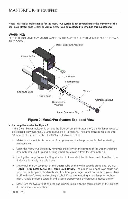
70DO NOT DIVE.
Quartz Tube
Enclosure Base
Assembly Pin
UV Reactor
Upper Enclosure Assembly
UV Lamp
Compression Washers
Compression Nut
Sealing Rings
Lamp Connector Plug
23
WARNING:BEFORE PERFORMING ANY MAINTENANCE ON THE MAST3RPUR SYSTEM, MAKE SURE THE SPA IS SHUT DOWN.
a. UV Lamp Removal – See Figure 2. If the Green Power Indicator is on, but the Blue UV Lamp Indicator is off, the UV lamp needs to be replaced. However, the UV lamp useful life is 18 months. The Lamp must be replaced after 18 months of use, even if the Blue UV Lamp Indicator is still lit.
i. Make sure the unit is disconnected from power and the lamp has cooled before starting maintenance.
ii. Open the Mast3rPur System by removing the screw on the bottom of the Upper Enclosure Assembly, rotating it up and pushing it back to release it from the Assembly Pin.
iii. Unplug the Lamp Connector Plug attached to the end of the UV Lamp and place the Upper Enclosure Assembly in a safe place.
iv. Slowly pull the UV Lamp out of the Quartz Tube by the white ceramic prong end. DO NOT TOUCH THE UV LAMP GLASS WITH YOUR BARE HANDS. The oils on your hands can cause hot spots on the lamp and shorten its life. If oil from your fingers is left on the lamp glass, clean it off with a soft towel and rubbing alcohol. If you are removing an old lamp for replace-ment, handle the lamp carefully and dispose properly (see Environmental Notice below).
v. Make sure the two o-rings and the end cushion remain on the ceramic ends of the lamp as it is set aside in a safe place.
DO NOT DIVE.
Mast3rPur (if equipped)
Figure 2: Mast3rPur System Exploded View
Note: This regular maintenance for the Mast3rPur system is not covered under the warranty of the spa. Your Master Spas Dealer or Service Center can be contacted to schedule this maintenance.

71DO NOT DIVE. 23DO NOT DIVE.
Mast3rPur (if equipped)
b. Installing the UV Lamp
i. Make sure to handle the new lamp as described in Section A and clean the UV Lamp before installation if needed.
ii. Slowly place the UV Lamp into the Quartz Tube until it contacts the bottom of the tube.
iii. Connect the Lamp Connector Plug to the pins on the lamp.
NOTE: Do not force the Lamp Connector Plug onto the pins. If force is needed, it means that the components are misaligned.
ENVIRONMENTAL NOTICE: UV Lamp CONTAINS MERCURY. Manage in accordance with disposal laws. See: www.lamprecycle.org
c. UV Reactor Service and Maintenance The UV Lamp is housed in a Quartz Tube. If the Quartz Tube becomes dirty, its ability to transmit rays from the UV Lamp will be diminished and decrease system performance. The Quartz Tube should be removed from the UV Reactor at least once a year, or during a routine spa water change for inspection and cleaning if necessary. DO NOT REMOVE THE QUARTZ TUBE WITH WATER IN THE SPA
d. Quartz Tube Removal and Cleaning
CAUTION: Wear proper eye and skin protection for servicing glass components.
i. Make sure the spa is shut down the water removed from the spa, and that the UV Lamp and Quartz Tube have cooled before performing maintenance on the Quartz Tube.
ii. Remove the Upper Enclosure Assembly and UV Lamp as described in Section A and set aside in a safe place.
iii. Remove the plastic Compression Nut. If there is any water remaining in the plumbing, it will start to leak after the Compression Nut is removed.
iv. Grasp the inside of the Quartz Tube and pull it out of the housing. Make sure the Sealing Rings and Compression Washers do not get lost during Quartz Tube removal.
v. Inspect the Sealing Ring for nicks or hardness and the Compression Washers for cracks, replace if necessary.
vi. Clean the Quartz Tube exterior with a mild solution of muriatic acid and water in a ratio of four parts water to one part acid (4:1). DO NOT USE ABRASIVE CLEANERS as they can scratch the high quality quartz glass.
CAUTION: Follow the directions for safe use and handling of muriatic acid on the acid bottle label.
vii. After cleaning the Quartz Tube, wash it off with water and wipe dry with a soft towel. Inspect the Quartz Tube for cracks and replace if cracks are found.
viii. Make sure the inside of the Quartz Tube is dry before replacing the UV Lamp(s).
NOTE: Damage caused by broken quartz tubes is not covered under the Mast3rPur System Limited Warranty.
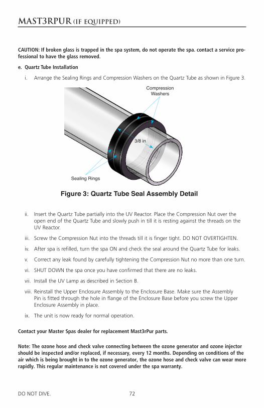
72DO NOT DIVE. 23DO NOT DIVE.
Mast3rPur (if equipped)
CAUTION: If broken glass is trapped in the spa system, do not operate the spa. contact a service pro-fessional to have the glass removed.
e. Quartz Tube Installation
i. Arrange the Sealing Rings and Compression Washers on the Quartz Tube as shown in Figure 3.
Sealing Rings
3/8 in
Compression Washers
Figure 3: Quartz Tube Seal Assembly Detail
ii. Insert the Quartz Tube partially into the UV Reactor. Place the Compression Nut over the open end of the Quartz Tube and slowly push in till it is resting against the threads on the UV Reactor.
iii. Screw the Compression Nut into the threads till it is finger tight. DO NOT OVERTIGHTEN.
iv. After spa is refilled, turn the spa ON and check the seal around the Quartz Tube for leaks.
v. Correct any leak found by carefully tightening the Compression Nut no more than one turn.
vi. SHUT DOWN the spa once you have confirmed that there are no leaks.
vii. Install the UV Lamp as described in Section B.
viii. Reinstall the Upper Enclosure Assembly to the Enclosure Base. Make sure the Assembly Pin is fitted through the hole in flange of the Enclosure Base before you screw the Upper Enclosure Assembly in place.
ix. The unit is now ready for normal operation.
Contact your Master Spas dealer for replacement Mast3rPur parts.
Note: The ozone hose and check valve connecting between the ozone generator and ozone injector should be inspected and/or replaced, if necessary, every 12 months. Depending on conditions of the air which is being brought in to the ozone generator, the ozone hose and check valve can wear more rapidly. This regular maintenance is not covered under the spa warranty.


Twilight Series is manufactured by Master Spas, one of the world’s
leading spa manufacturers.
Master Spas Inc. 6927 Lincoln Parkway Fort Wayne, IN 46804
800.860.7727
[email protected] www.MasterSpas.com
Master Spas reserves the right to change specifications or features without notice. Master Spas is a manufacturer of spas and related products and we stand behind every product we produce pursuant to those representations which are stated in our written limited warranty. your dealer is an independent business person or company and not an employee or agent of Master Spas, Inc. We cannot and do not accept any responsibility or liability for any other representations, statements or contracts made by any dealer beyond the provisions of our written limited warranty.
POP15TSOM201412