owners manual installation instructions for models · owners manual installation instructions ....
TRANSCRIPT

For Models • PTRO-50
Owners Manual Installation Instructions

Page 2 Table of Contents
Subject Page
PURE TECH 1000 Features 3
What is Reverse Osmosis 4
System Overview 9
Installation 10
Warranty 14
Notes 15
Tech Support: 1-888-989-7873 PURE WATER TREATMENT, INC.
P.O. Box 730486 Ormond Beach, FL 32173-0486
1-888-989-(PURE) 7873 Office • 1-877-219-(PURE) 7873 Fax
Copyright© 2003 all rights reserved
Tech Support: 1-888-989-7873 PURE WATER TREATMENT, INC.
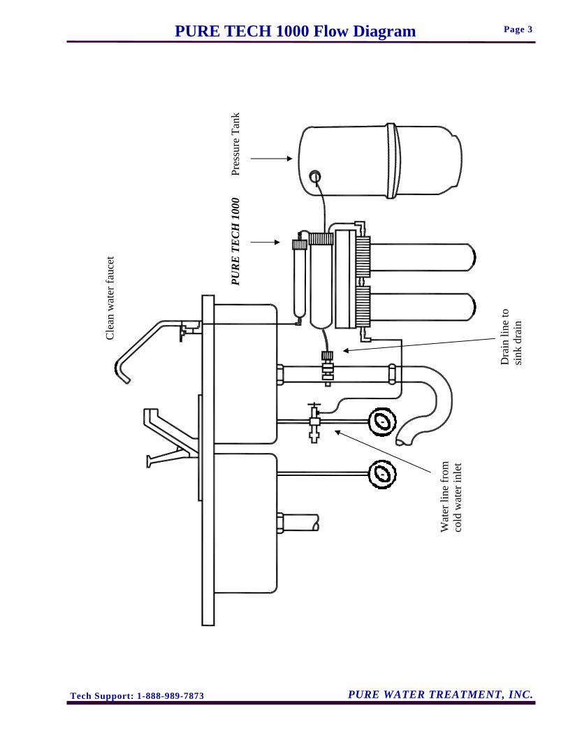
Page 3 PURE TECH 1000 Flow Diagram
Pres
sure
Tan
k PU
RE
TE
CH
100
0
Dra
in li
ne to
si
nk d
rain
Wat
er li
ne fr
om
cold
wat
er in
let
Cle
an w
ater
fauc
et
Tech Support: 1-888-989-7873 PURE WATER TREATMENT, INC.
Page 4
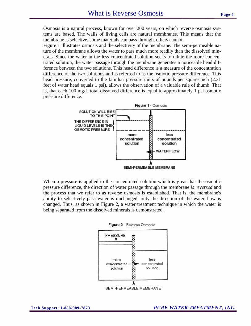
Osmosis is a natural process, known for over 200 years, on which reverse osmosis sys-tems are based. The walls of living cells are natural membranes. This means that the membrane is selective, some materials can pass through, others cannot. Figure 1 illustrates osmosis and the selectivity of the membrane. The semi-permeable na-ture of the membrane allows the water to pass much more readily than the dissolved min-erals. Since the water in the less concentrated solution seeks to dilute the more concen-trated solution, the water passage through the membrane generates a noticeable head dif-ference between the two solutions. This head difference is a measure of the concentration difference of the two solutions and is referred to as the osmotic pressure difference. This head pressure, converted to the familiar pressure units of pounds per square inch (2.31 feet of water head equals 1 psi), allows the observation of a valuable rule of thumb. That is, that each 100 mg/L total dissolved difference is equal to approximately 1 psi osmotic pressure difference. When a pressure is applied to the concentrated solution which is great that the osmotic pressure difference, the direction of water passage through the membrane is reversed and the process that we refer to as reverse osmosis is established. That is, the membrane's ability to selectively pass water is unchanged, only the direction of the water flow is changed. Thus, as shown in Figure 2, a water treatment technique in which the water is being separated from the dissolved minerals is demonstrated.
What is Reverse Osmosis

Tech Support: 1-888-989-7873 PURE WATER TREATMENT, INC.
Page 5
Were the membrane to act as a perfect separator, the permeate would contain 0-mg/L to-tal dissolved solids, no matter what the concentration on the feed side of the system. This is not the case, however. And, in fact, let us consider, for the sake of illustration, 90% re-jection to be an average operating condition. By considering the mechanism of salt and water passage through the membrane, it will be clear why complete salt elimination is not possible and how operating conditions can effect permeate quality and quantity. The membrane's ability to hold back salts while allowing water to pass is based on the fact that the salts are in solution as ions, that is, charged particles. The dissolved salts are in solution as cat ions, with a positive charge, and as anions, with a negative charge. A descriptive analogy of what is happening is to consider the membrane to be a mirror. As the charged particles, ions, approach the membrane, they are repelled by a reflection of their own charge. That is, similar charges repel, just as similar magnetic poles repel each other. Therefore, the layer of water immediately adjacent to the membrane is void of charged particle, and it is this water which will subsequently diffuse through the pores and be delivered as permeate. Since the anions and citations are constantly moving around in solution, sometimes they are near enough to each other to be attracted to one another, thus canceling their individual charges. Without a net charge, these particles are free to pass through the membrane. Although Figure 2 was sufficient to illustrate the basic RO process, the feed and concen-trate ports added in Figure 3 are necessary to illustrate a continuously operating RO sys-tem. In order to keep the membrane from fouling it is important to continually flush the brine side. As the water is squeezed through the membrane, leaving most of the salts behind, the brine side solution becomes increasingly concentrated. Without the reject flow to drain, the brine side mineral concentration would eventually exceed the solubility limits of the salts present and they would precipitate, forming a scale on the membrane. To avoid excessive brine side concentrations, the permeate volume recovered, in a low pres-sure system, is usually kept in the range of 1- to 30 percent of the feed stream volume. For example, if for each five gallons of water fed to the membrane, one gallon of perme-ate is recovered, the membrane is operating at 20% recovery.
What is Reverse Osmosis cont.

Tech Support: 1-888-989-7873 PURE WATER TREATMENT, INC.
Page 6
REVERSE OSMOSIS MEMBRANES Construction The semi-permeable membrane used RO systems are cast polymer films of asymmetric density. That is, they have a dense barrier layer which is very thin, perhaps 10 millionths of an inch, supported on a more porous substrate a few thousandths of an inch thick. Figure 4 illustrates the different densi-ties in the cross section of the membrane. Configurations Different configurations of membranes have been devised, each offering certain advantages. The most popular membrane configuration is the spiral wound, shown below in Figure 5. These are assembled by folding a sheet of membrane over a tube, referred to as the prod-uct tube, and trapping a screen between the two halves of the membrane. The membrane is bonded to the tube and glued together along the three open edges. Another spacer screen is laid on the membrane and the whole sandwich is rolled tightly around the prod-uct tube and then bound with tape to hold it together. This method of packaging mem-brane provides considerably more surface area per module than the tubular. However, since the feed water must wind its way through the path created by the spacer screen, dirt particles can be easily trapped, so 5 micron pre-filtration is generally recommended. Reverse Osmosis Operation The general operation of all RO modules is the same. The feed stream is supplied to the membrane and split into the permeate which has diffused through the membrane, and the concentrate which passes over the membrane, carrying away the minerals to waste.
What is Reverse Osmosis cont.
Tech Support: 1-888-989-7873 PURE WATER TREATMENT, INC.
Page 7
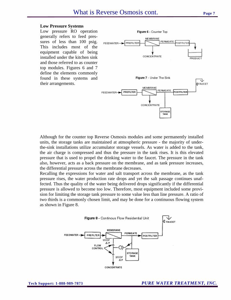
Although for the counter top Reverse Osmosis modules and some permanently installed units, the storage tanks are maintained at atmospheric pressure - the majority of under-the-sink installations utilize accumulator storage vessels. As water is added to the tank, the air charge is compressed and thus the pressure in the tank rises. It is this elevated pressure that is used to propel the drinking water to the faucet. The pressure in the tank also, however, acts as a back pressure on the membrane, and as tank pressure increases, the differential pressure across the membrane decreases. Recalling the expressions for water and salt transport across the membrane, as the tank pressure rises, the water production rate drops and yet the salt passage continues unaf-fected. Thus the quality of the water being delivered drops significantly if the differential pressure is allowed to become too low. Therefore, most equipment included some provi-sion for limiting the storage tank pressure to some value less than line pressure. A ratio of two thirds is a commonly chosen limit, and may be done for a continuous flowing system as shown in Figure 8.
What is Reverse Osmosis cont.
Low Pressure Systems Low pressure RO operation generally refers to feed pres-sures of less than 100 psig. This includes most of the equipment capable of being installed under the kitchen sink and those referred to as counter top modules. Figures 6 and 7 define the elements commonly found in these systems and their arrangements.

Tech Support: 1-888-989-7873 PURE WATER TREATMENT, INC.
Page 8
When the storage tank has been filled to the point at which its pressure equals two thirds of line pressure, the permeate is diverted to drain. To conserve water consumption in reverse osmosis devices another type of control called "shutdown" is employed in the design using a shutoff valves and is illustrated in Figure 9. At the designed-in, present ration, the storage tank pressure will close the valve and pre-vent further feed to the system. The valve will open again when sufficient pressure reduc-tion is sensed at the storage tank. Whatever means is used to accomplish shut down, the end result is that the differential pressure across the membrane is eliminated so that water production ceases. Unless pro-vision is made to eliminate the dissolved mineral concentration difference across the membrane, salt passage will continue, creating a high TDS water on the permeate side of the membrane. This phenomena is commonly referred to as a TDS creep
What is Reverse Osmosis cont.
Tech Support: 1-888-989-7873 PURE WATER TREATMENT, INC.
Page 9
Your Drinking Water System has been tested to ensure it will operate correctly. The fol-lowing periodic maintenance is recommended so your system will provide years of trou-ble-free service:
Replacement parts Replacement Pre-filters (sediment) Every 6 mos. Post-filters (activated carbon) Every 6 mos. Components The following components make up you drinking water system. Pre-filter (s) -sediment– removes larger particles such as sand, silt, rust and scale. Post-filter –activated carbon– removes chlorine in the feed water to protect the
System Overview

Tech Support: 1-888-989-7873 PURE WATER TREATMENT, INC.
Page 10
Note: All plumbing must be completed in accordance with state and local plumbing codes. Some municipalities may require installation by a licensed plumber. Check local authority prior to installation.
1. Faucet Installation: If the sink has a sprayer it may be disconnected for faucet instal-lation. (Installing dealers should discuss the with customers.) A pipe cap or plug will be necessary to seal the sprayer connection. To make the faucet mounting hole (if sprayer or second hole is not used), check below to make sure the drill does not interfere with anything below. Center punch a small indent at the desired faucet location. (2” flat sur-face is required, not exceeding 1-1/4” in thickness.) Drill the required pilot hole for the chassis punch and tighten nut to cut the desired hole size. Clean up sharp edges. The faucet should be positioned so it empties into the sink and the spout swivels freely for convenience. If sink has a hole that can accommodate the faucet, no drilling is required. Proceed with mounting faucet.
Porcelain, Enamel, Ceramic on Metal or Cast Iron: Precaution must be taken to penetrate the porcelain through to the metal base and prevent it from chipping or scratching.
Tools Required: • Variable Speed Drill • Relton porcelain cutter tool set (7/8” or alternative size, 9/16”) • Plumber’s putty Procedures:
1. Mark the center for the 7/8” hole. Form shallow putty around hole area and fill with enough water to lubricate carbide drill bit.
2. Carefully drill pilot hole through all lay-ers. (Use light pressure and slow speed.)
3. Insert pilot tip of spring-loaded porcelain cutter into pilot hole.
4. Drill porcelain/enamel using spring loaded porcelain cutter, making certain a com-plete ring has been cut through the porce-lain/enamel to the metal base.
5. Cut away the inner porcelain/enamel disc down to the base metal. Make certain the cutter does not touch outer rim of the cut porcelain/enamel. Continue until the sink has been completely penetrated.
Installation
Faucet Installation without air gap
Tech Support: 1-888-989-7873 PURE WATER TREATMENT, INC.
Page 11 Installation (cont.)
Installation procedures for stainless steel sinks Recommended tools: • Center Punch • Variable Speed Drill • High speed drill bits • Greenlee chassis punch 7/8” (or 9/16” for non-air gap faucets) • Protective gloves & eye protectors Procedures:
1. Center punch small indent for hole. 2. Drill the required pilot hole. 3. Set-up the chassis punch per instructions and tighten nut to cut the desired hole size. 4. Clean up sharp edges with file.
2. Mounting the faucet Disassemble hardware from the threaded nipple, except for chrome base plates and rub-ber washers. (Rubber washers may be replaced with bead of plumber’s putty for neater appearance.) Feed the threaded nipple through sink or counter mounting hole and orient the faucet. From below sink or counter, assemble the white spacer flat washer and hex nut on threaded nipple and tighten by hand. (Open end up, open side toward air gap.) After checking faucet orientation, tighten with a wrench until secure.
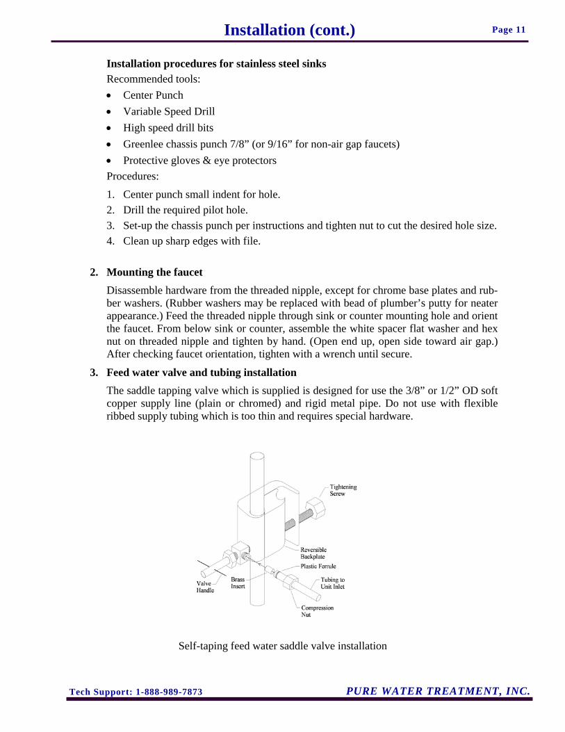
3. Feed water valve and tubing installation The saddle tapping valve which is supplied is designed for use the 3/8” or 1/2” OD soft copper supply line (plain or chromed) and rigid metal pipe. Do not use with flexible ribbed supply tubing which is too thin and requires special hardware.
Self-taping feed water saddle valve installation

Tech Support: 1-888-989-7873 PURE WATER TREATMENT, INC.
Page 12 Installation (cont.)
Installation procedures using soft copper tubing: 1. Turn off cold water valve from under sink or main water line valve for whole house. 2. Before installing saddle tapping valve, make sure piercing lance does not protrude
beyond rubber gasket. 3. Assemble valve on copper tubing. 4. Turn handle clockwise to pierce soft copper tube until valve is firmly seated. (Valve
is closed in this position.) 5. Turn on water supply to pressure cold water line. 6. Snug nut/seal with wrench around valve stem. 7. Connect tubing to feed water valve using brass compression nut, insert and plastic
sleeve.
Saddle valve installations with metal pipe: 1. Turn off cold water supply. 2. Drill 3/16” hole at desired location. 3. At this point, make sure piercing lance does not protrude beyond rubber gasket. 4. Assemble saddle on to pipe, aligning with hole. 5. Turn saddle valve handle clockwise to close valve. 6. Tighten nut/seal around valve stem with wrench. 7. Connect tubing to feed water valve using brass compression nut, insert and plastic
sleeve. 8. Turn on cold water supply. To open valve, turn handle counterclockwise and check for leaks.
4. Initial tubing connections For convenience on under counter installations it may be advisable to complete under counter hose connections at this time.
5. Unit installation To mount the drinking water unit, elevate it at least 2” off the floor, level it and mark the location of mounting holes needed. Drill holes for mounting screws and install screws, allowing the mounting bracket slots to slip over them. NOTE: If the cabinet sidewalls are not solid, unit may sit on the floor with screws to keep it against the cabi-net in a vertical position.
6. Final Tubing installation With all components in place, complete final tubing connections using these guidelines: • Tubing should follow contour of the cabinets. • Cut tubing to desired length using square cuts and proper cutting device. • Make no sharp bends. Keep tubing from the unit to the faucet as short as practical for good flow.
Tech Support: 1-888-989-7873 PURE WATER TREATMENT, INC.
Page 13 Installation (cont.)
Under sink installations fooling installation diagram and the following procedures: 1. Connect tubing from faucet to unit. 2. Connect tubing from supply valve to unit. Icemaker hookup (optional) The drinking water device can be connected to any standard refrigerator ice make or ice maker/water dispenser. (Do not connect to a commercial type bar ice maker.) To com-plete this operation, connect a tee with shutoff valve into faucet tubing and route tubing to the refrigerator. (Hooking up to an existing copper line is not recommended unless it is new installation.) Shut off ice maker by lifting lever prior to turning off the existing tap water supply line to the refrigerator. System start-up Prior to start-up: 1. Check all connections be sure they are secure. 2. Turn on feed water valve and check for leaks. (Turn off and correct leaks if leak
occur.) 3. Close faucet and wait five minutes to see if leaks result. NOTE: When the system is first turned on, water may intermittently “spurt” from the air gap opening on the side of air gap faucets. This is common and should correct itself after an initial period of time. Maintenance Your drinking water system contains filter cartridges which must be replace periodi-cally for proper operation. (Please see page 4 for general change out recommendations.) NOTE: Change out procedures may be amended, depending on source water condi-tions. To change filter cartridges follow these procedures: 1. Close feed water valve by turning it clockwise. 2. Loosen and remove filter housing using wrench provided and discard cartridges. 3. Wash the inside of the housings using mild detergent and soft cloth. Thoroughly
rinse all soap before reassembly. 4. Replace filter cartridges.
John Guest® brand fittings The PURE TECH 1000 utilizes John Guest® brand fittings. These user-friendly fittings provide superior performance and virtually eliminate the potiential for leaks. Proper use of these push-in fittings is shown below. Along with these fittings, all tubing selecteed must be high quality and must be cut with a plastic tuber cutter or sharp razor with a clean, square cut. Should a leak occur at a fitting, the cause is generally defective tubing. To fix a leak, relieve pressure, release tubing, cut off at least 1/4” from the end (square cut), reattach the tubing and confirm the connection is leak free. Each time a new connecion is made, it is advisable to cut off 1/4” from the end of the tubing using these fittings.
Conventional fittings If John Guest fittings are not used, it is essential to install inserts at the ends of all tube connections when conventional fittings are used.
10 YEAR WARRANTY FOR RESIDENTIAL APPLICATIONS
Congratulations on the purchase of your PURE TECH Water System. PURE WATER TREATMENT, INC. warrants its products to be free from defects in material and workmanship according to the following terms and conditions:
What is Covered? I. The PURE TECH 1000 series. 10 YEARS ON PARTS EXCLUDING FILTERS. ______________________________________________________________________________________
Who is Covered? This product warranty is transferable to a subsequent owner. The only requirement is that the system must remain at the site of original installation. ______________________________________________________________________________________
Extension of Warranty to a Subsequent Installa-tion The ORIGINAL OWNER may move the system to another location. The influent water quality at the subsequent loca-tion MUST, however, be within your system’s operating specifications. Please contact a local authorized PURE TECH dealer prior to installation at another location. ______________________________________________________________________________________
Registration and Service To place your system under warranty, your authorized PURE TECH dealer should complete the owner’s registra-tion form and return one copy to: PURE WATER TREAT-MENT, INC., P.O. Box 730486, Ormond Bch, FL 32173-0486, within 30 days of the installation date. For service under this warranty, you should contact the dealer. Retain a copy of this warranty for reference if service is necessary.
Limits on this Warranty Your system must be sold to you by an authorized PURE TECH dealer in order to receive coverage under this war-ranty. Additionally, this warranty does not cover products installed for commercial, industrial, institutional or multi-family applications.
The design of the overall treatment system and performance of your system is related to the chemistry of the water being treated; therefore, This warranty is limited to the equipment manufactured and distributed by PURE WATER TREATMENT, INC. This Warranty does not include damage to your system due to: • Abuse, misuse or neglect • Excessive pressure (over 100 psi for a PURE TECH 1000 system, or 125 psi for all other PURE TECH systems) • Excessive water temperature (over 100° for a PURE TECH
1000 system, or 120° for all other PURE TECH systems)
• Freezing, alterations or misapplication • A change in the influent water characteristics
Your equipment must be installed and operated in accordance with your owners manual’s recommendations and applicable state and local codes.
______________________________________________________________________________________
No Other Warranties There is no other express warranty. Implied warranties
including any warranty of merchantability or fitness for a par-ticular purpose, are limited to the duration of this warranty and are excluded to the extent permitted by law. There are no warran-ties other than those contained herein. In no event shall the com-pany be liable for indirect, special or consequential damages in connection with the use of the system. ______________________________________________________________________________________
Modification of the Warranty PURE WATER TREATMENT, INC. does not author-
ize any other person to assume for PURE WATER TREATMENT, INC. any other liability in connection with this product.
The dealer has no authority to make any representa-tions on behalf of PURE WATER TREATMENT, INC. or to modify the terms of this warranty in any way.
P.O. Box 730486 Ormond Beach, FL 32173-0486
OFFICE 1-888-989-PURE · FAX 1-877-219-PURE “Our Reputation Is Worth More Than Money”
Tech Support: 1-888-989-7873 PURE WATER TREATMENT, INC.
Warranty Page 14

Tech Support: 1-888-989-7873 PURE WATER TREATMENT, INC.
Page 15
_________________________________________________________________
_________________________________________________________________
_________________________________________________________________
_________________________________________________________________
_________________________________________________________________
_________________________________________________________________
_________________________________________________________________
_________________________________________________________________
_________________________________________________________________
_________________________________________________________________
_________________________________________________________________
_________________________________________________________________
_________________________________________________________________
_________________________________________________________________
_________________________________________________________________
_________________________________________________________________
_________________________________________________________________
_________________________________________________________________
_________________________________________________________________
_________________________________________________________________
_________________________________________________________________
_________________________________________________________________
_________________________________________________________________
Notes