owner's manual model sl505
TRANSCRIPT

1
OWNER'S MANUALMODEL SL505
RESIDENTIAL SLIDE GATE OPERATORS
2 YEAR WARRANTY
Serial # _____________________(located on electrical box cover)
Installation Date:_______________
SL505 GATE OPERATORS ARE FOR USE ON VEHICULAR PASSAGESONLY AND NOT INTENDED FOR USE ON PEDESTRIAN PASSAGE GATES.

2
Contents
General Information...........................................................................................................3-4
Features...............................................................................................................................5-6
Parts Identification..............................................................................................................7-8
Installation.........................................................................................................................9-11
Page
Electrical..........................................................................................................................12-16
Fine Tuning.......................................................................................................................16
Master/Second........................................................................................................................17
Wiring Diagrams..............................................................................................................18-20
Notes......................................................................................................................................28, 29
Troubleshooting...............................................................................................................25-27
Maintenance & Safety........................................................................................................24
Options............................................................................................................................22,23
Safety Edge and Safety Warning Placard Installation....................................................21
IMPORTANT SAFETY INSTRUCTIONS
WARNING - To reduce the risk of injury or death:1) READ AND FOLLOW ALL INSTRUCTIONS2) Never let children operate or play with gate controls. Keep the remote control away from children.3) Always keep people and objects away from the gate. NO ONE SHOULD CROSS THE PATH OF THE MOVING GATE.4) Test the gate operator monthly. The gate MUST reverse on contact with a rigid object or stop when an object activates the non-contact sensors.After adjusting the force or the limit of travel, re-test the gate operator. Failure to adjust and re-test the gate operator properly can increase the risk ofinjury or death.5) Use the emergency release only when the gate is not moving.6) KEEP GATES PROPERLY MAINTAINED. Read the owner's manual. Have a qualified service person make repairs to gate hardware.7) The entrance is for vehicles only. Pedestrians must use separate entrance.8) SAVE THESE INSTRUCTIONS.

3
General Information
Overall Dimensions: Height: 23" Length: 11" Width: 8"
Shipping Weight: OPERATOR:53 lbs CHAIN PACKAGE:12 lbs MOUNTING POSTS:16 lbs TOTAL: 81 lbs
Options: OPERATOR + BATTERY RUN PACKAGE: 59 lbs LOW VOLTAGE CABLE: 1 lbs/10 ft CONCRETE MOUNTING STAND: 17 lbs
Applications: MAXIMUM GATE WEIGHT: 375 lbs MAXIMUM GATE LENGTH: 20 ft
POWER REQUIREMENT: Dedicated 115 VAC (+/- 10V) , 5A Power CircuitNOTE: For standard operator, place 115 VAC at or near the operator.
For Battery Run operator, place 115 VAC within 1,000 ft of the operator.
There are three possibilities for supplying power to the SL 505 gate operator. The standard power supply version ismade to connect directly to 115 Volt, 5 Amp power source and is available for full systems capability models. This powersupply must be at or near the gate operator location. Because of the low current draw, 115 Volt power may be run as far as1000 feet with 12 gauge wire from the main breaker panel and can be run much farther with larger wire. Another possibility forsupplying power to the operator is with the low voltage battery run version of the SL 505. To supply power to the SL 505battery run, wire as small as 16 gauge can be run as far as 300 feet from a charger that is plugged in remotely. Because thepower is low 12 Volt DC, the wire can be direct burial wire which eliminates the need for expensive conduit runs. The otherpossibility for supplying power to the SL 505 is with the Solar power version of the operator. The Solar model does not requireany power to be run because the operator and solar power supply are self contained. The panel may be placed severalhundred feet from the operator if this is necessary to achieve maximum sunlight conditions.

4
General Information
INCLUDED WITH OPERATOR:Check package to make sure it contains the following items.STANDARD GATE OPENER
1-Model SL 505 gate operator 2-Mounting Posts 2" Diameter x 30" 2-Gate/Chain Brackets, U-Bolt type 2-U-Bolts Round 2-U-Bolts Square 1-Chain #40 x 25 ft 2-Master Links #40 2-Chain Bolts 2-Self Tapping Screws 1-Hex Key for Cover 2-Manual Release Keys 2-Safety Warning Placards
BATTERY RUN ONLY (OPTIONAL) 1-Burial cable, 10 ft 1-Charger, 12 Volt 1-Battery, 12 Volt (installed)
SOLAR ONLY (OPTIONAL) 3-Pipe sections, 1" X 24" 2-Pipe couplings, 1" 1-Solar Panel Assembly 5-Lock Rings 2-Batteries, 12 Volt (installed)
(See parts identification.)
Vehicular Gate Operator Classes: Class I - Residential Vehicular Gate Operator: A vehicular gate operator (or system) intended for use in a home of
one-to four single family dwellings, or a garage or parking area associated therewith.Class II - Commercial/General Access Vehicular Gate Operator: A vehicular gate operator (or system) intended for
use in a commercial location or building such as a multi-family housing unit (five or more single family units), hotel, garage, retail store, or other building servicing the general public.
Class III - Industrial/Limited Access Vehicular Gate Operator: A vehicular gate operator (or system) intended for use in an industrial location or building such as a factory or loading dock area or other locations not intended to service the general public.
Class IV - Restricted Access Vehicular Gate Operator: A vehicular gate operator (or system) intended for use in a guarded industrial location or building such as an airport security area or other restricted access location not servicing the general public, in which unauthorized access is prevented via supervision by security personnel. Gate Operator model SL 505 is intended for Vehicular Gate Operator Classes I, II, III, and IV.
Gate Inspection:a) Install the gate operator only when:
1) The operator is appropriate for the construction of the gate and the usage Class of the gate,2) All openings of a horizontal slide gate are guarded or screened from the bottom of the gate to a minimum of 4 feet (1.2 m) above the ground to prevent a 2-1/4 inch (57.15 mm) diameter sphere from passing through the openings anywhere in the gate, and in that portion of the adjacent fence that the gate covers in the open position.3) All exposed pinch points are eliminated or guarded, and4) Guarding is supplied for exposed rollers.
b) The operator is intended for installation only on gates used for vehicles. Pedestrians must be supplied with a separate access opening.c) The gate must be installed in a location so that enough clearance is supplied between the gate and adjacent structures then opening and closing to reduce the risk of entrapment.d) The gate must be properly installed and work freely in both directions prior to the installation of the gate operator. Do not over-adjust the gate sensitivity to compensate for a damaged gate.
Mounting:There are two ways to mount the SL 505 operator. One way to mount the operator is to attach it with bolts to a
concrete surface using the optional concrete mounting stand and sleeve anchors. In some cases there will already be anexisting concrete surface or pad available to bolt the operator to. If there is no existing concrete surface or pad, it is veryeasy to fashion one so that the operator can be bolted down at a later time using sleeve anchors. The other way to mountthe SL 505 operator is directly into the earth with the two 2" X 30" mounting posts that have been provided. For thisinstallation the posts are attached to the operator, one post hole is made in the earth and then the operator with postsattached is set in place. The cement can then be poured into the post hole and will dry within minutes if concrete acceleratoris used. The operator can be put into full operation the very same day.

5
Features
FULL SYSTEMS CAPABILITY Sensitivity
As with other LiftMaster gate openers, the SL 505 has a built-in safety feature which when adjusted properly willdeliver only enough power to the motor to overcome the resistance of the gate. What this means is that if the gate runs into avehicle or pedestrian, the gate will immediately stop or reverse. Because of the DC motor technology incorporated into theSL 505, the sensitivity feature is much more sensitive and is at least 50% more effective than traditional AC current sensors.
Soft Start/Soft StopA unique feature of the SL 505 is the Soft Start/Soft Stop feature. Traditional gate openers will begin opening the
gate with full power causing a yanking or jerking effect that severely decreases the life of mechanical parts. The SL 505 willbegin opening or closing the gate very slowly and will then increase to full speed. This creates a very gentle gate transitionwhich considerably reduces the amount of wear and tear on all mechanical parts.
Manual Release Key SwitchThis simple on-off key switch is built into the side of the operator. In an emergency, even with the power off, the gate
can be pushed open manually after turning the key counter-clockwise. Electronic Brake
Traditional gate openers typically have a mechanical brake or clutch which requires special maintenance. The DCmotor technology that is incorporated into the SL 505 provides the gate opener with a brake that will never wear out. Thispatented feature causes the gate to come to a stop and keeps the gate locked when stopped in any position.
Battery Run/Low Voltage (Optional)The SL 505 is available in both battery run and solar versions. The main and most obvious benefit to having battery
run or solar is the ability to open and close the gate even when there is no power. This in itself provides an extremely highlevel of convenience. If there is a power failure the gate will operate as it normally does and can be opened up to 150 timesbefore power is restored. Another very important benefit to having battery run is that it is not necessary to have 115 Volts atthe operator location because running high voltage is typically very expensive and highly regulated. All that is needed tosupply power to a battery run version of the SL 505 is some inexpensive low voltage burial cable. If the cable is 16 gauge itcan be run as far as 300 feet. For solar versions of the SL 505, no power needs to be run to the operator. The solar versionhas a solar panel which is normally attached to the gate opener but can placed anywhere that allows the panel to receivemaximum sunlight.
Visual FeedbackThe SL 505 Full Systems Capability circuit board has been equipped with visual feedback LEDs (small indicator
lights) to help simplify installation and troubleshooting. There are LEDs located directly beside each input terminal to indicateif any input devices are active. There are also two LEDs which indicate that the circuit board is delivering power to the motorand are labeled O and C for either the Opening or Closing directions of travel respectively. Collectively, all of the LEDscombined provide quick glance information to the installer or service technician showing visually what is happening in thenormally invisible operation of the circuit board.

6
Features continued...
Auto Close TimerThe operator comes factory preset with the auto close timer function OFF. The auto close timer will close the gate
automatically after a specific amount of time has elapsed. The amount of time can be easily adjusted between 0 and 45seconds by turning a small "pot" located on the edge of the circuit board (See page 17). The timer can be disabled oractivated by flipping a single switch located on the top edge of the circuit board. If the timer will be used it is recommendedthat some type of supplementary safety device (loops, photo beam etc.) be installed.
Gate Sensitivity AdjustmentThe amount of force necessary to stop the gate can be adjusted to conform to the various sizes and weights of any
particular gate. The full systems capability circuit board provides separate adjustments for both the opening and closingdirection. When adjusting the sensitivity, the operator can be given only as much energy as is necessary to overcome theresistance of the gate. If the gate should strike an obstruction either direction, the gate will reverse. If the gate should againstrike an obstruction before reaching a limit, the gate will stop and remain stopped. (See page 17)
Master And SecondSome very large entrances may require the use of two gates. If this is the case, the two gates can be easily
automated using the "Master and Second" configuration. This configuration uses two gates and two operators in ONEdriveway. The Full systems capability models have terminals provided especially for Master and Second applications and willreliably operate simultaneously all of the time.
Pulse Open InputThe Pulse Open input feature is an open input on the circuit board which will increase the security of the SL 505
gate operator system. When an open input device such as a key switch is connected to the Pulse Open input, and thedevice is activated, the gate operator will activate but will then ignore the input if the input is prolonged. What is significantabout this feature is that there is the possibility of a device being stuck and if the device is connected to the standard openinput the gate will be held open. If the device is connected to the Pulse Open input on terminals 6 and 7, the circuit board willignore the stuck input and will allow the gate to close. For added security any open input device may be used with PulseOpen including push buttons, key switches, numerical key pads etc.
PeripheralsPOWER SUPPLY: There is 12 Volts DC .1 AMP available on the circuit board which is used to supply power to a radio
receiver or other device.OPEN INPUT: Normally open devices are connected to terminals 5 and 6 on the circuit board to cause the gate to open
and/or close in PUSH-TO-OPEN/PUSH-TO-CLOSE (Timer switch OFF) mode of operation. Normally open devices are connected toterminals 5 and 6 to cause the gate to open in AUTO CLOSE TIMER (Timer switch ON) mode of operation. In this mode of operationthe AUTO CLOSE TIMER will automatically close the gate after a specific amount of time has elapsed. The Auto Close Timer isadjustable between 0-45 seconds. These normally open devices can be push buttons, key switches, loop detectors, photo electricbeams, 24 hour timers, etc. See FEATURES on the next page for other open input capabilities.
PULSE OPEN INPUT: Normally open devices are connected to terminals 6 and 7 on the circuit board to cause the gate toopen. Pulse Open Input functions identical to Open Input with the exception that it will not hold open the gate. If an open device isstuck on, the gate will still close. This feature is sometimes used to provide a higher level of security but should be used only inaddition to another open device connected to Open Input so the gate can still be opened if necessary.
SAFETY INPUT: Normally open devices are connected to terminals 4 and 6 on the SL 505 circuit board to cause the gateoperator to open and/or hold the gate open in any position except the fully closed position. Normally open safety input devices thatcan be used are push buttons, radio receivers, key switches, loop detectors, photo electric beams, 24 hour timers, etc.
N.C. STOP INPUT: Normally closed devices are connected to terminals 8 and 9 on the circuit board after removing thestop jumper that is on terminals 8 and 9. The N.C. Stop Input will cause the gate to stop at any position and will remain stopped untilactivated to open or close.
N.O. STOP INPUT: Normally open devices are connected to terminals 9 and 11 to cause the gate to stop in any positionuntil the gate is again activated to open or close. N.O. Stop Input functions identical to N.C. Stop input with the exception that itrequires normally open contacts instead of normally closed contacts.
CLOSE INPUT: Normally open devices are connected to terminals 9 and 10 on the circuit board to cause the gateoperator to close the gate when in any position. Normally open input devices that can be used are push buttons, radio receivers, keyswitches, loop detectors, photo electric beams, 24 hour timers, etc.

7
Parts Identification

8
Parts Identification continued...
K75-40047 SERVICE KIT
K75-40068 SERVICE KIT
MOTOR REDUCER ASSEMBLY
IDLER SPROCKET
ITEM PART # DESCRIPTION QTY
DESCRIPTION QTY
DESCRIPTION QTY
1 13-40067 LIMIT NUT 2
LIMIT NUT 2
SPROCKET, 41B14, 3/16" KW, (2) 1/4" SS 1
2 02-40075 KEY RELEASE SWITCH, 10A, SPST 1
MOTOR,REDUCER, 12 VOLT DC 1
BEARING, 1/2" ID x 3/4" OD x 1/2" 1
3 15-41B11CCB SPROCKET, 41B11, ½" BORE, ½ KW, 2SS 1
HEX BOLT, 3/8-16 X 3/4" 3
HEX BOLT, 5/8-11 X 2-3/4", GRADE 5 1
4 21-40074 XFMR, 120V, 60HV 1
FLATWASHER, 3/8" 3
HEX JAM NUT, 5/8-11 2
5 23-40050 LIMIT SWITCH 2
LOCKWASHER, 3/8" 3
LOCKWASHER, 5/8 1
6 25-40083 OVERLOAD, 1.5 AMP 1
7 28-40029 PIPE, 1" NPT X 24" 2
K74-40084 SERVICE KIT
K74-40041 SERVICE KIT
8 29-40071 RESISTOR, 1 OHM, 25W, OHMITE 1
BRIDGE RECTIFIER
OPERATOR COVER
9 29-40089 SONALERT PIEZO ALARM 1
DESCRIPTION QTY
DESCRIPTION QTY
10 29-40095 CHARGER, BATTERY 12V.5A DUAL STG 1
CAPACITOR, RECTIFIER 1
COVER, SL505 1
11 29-NP712 BATTERY, 12V 7AH 2
BRIDGE RECTIFIER 1
LABEL, BUBBLE, 4" X 2" 1
14 81-40034 MODULAR CONNECT, SP, WHITE 1
SCREW, PH PHILLIPS, #6-32 X 1" 1
SCREW, SOCKET, 3/8-16 X 1" 1
15 81-40035 MODULAR CONNECT, SP, YELLOW 1
FLANGE NUT, 6-32 1
FLATWASHER, 3/8" 1
16 K79-40056 PCB, COMPLETE, FULL SYSTEM 1
WASHER, 5/16, INTERNAL GRIP, PLASTIC 1
17 K79-40091 PCB, COMPLETE, SL505-BR 1
K74-40045 SERVICE KIT
18 K79-40098 PCB, COMPLETE, SOLAR 1
PCB GUARD AND STANDOFF
K74-40032 SERVICE KIT
DESCRIPTION QTY
SOLAR PANEL (OPTIONAL)
GUARD, PCB 1
DESCRIPTION QTY
JUMPER, PCB 3
SOLAR BRACKET 1
HEX STANDOFF, 6-32 x 1", M/F 4
SOLAR PANEL, 12V, 5 Watt 1
HEX STANDOFF, 6-32 x 1/2", F/F 4
MODULAR CONNECT, SP, WHITE 1
SCREW, PH PHILLIPS, #6-32 X 1/4" 4
MODULAR CONNECT, SP, YELLOW 1
SCREW, PH PHILLIPS, #6-32 X 3/8" 4
SCREW, PH PHILLIPS, #8-32 X 5/8" 2
SCREW, PH PHILLIPS, #1/4-20 X 5/8" 2
K74-40065 SERVICE KIT
FLANGE NUT, 8-32 2
EXTERNAL RESISTOR
FALNGE NUT, 1/4-20 2
DESCRIPTION QTY
EXTERNAL CURRENT RESISTOR 1
K74-40044 SERVICE KIT LIMIT
SHRINK WRAP, 1" 2
LIMIT SWITCH AND PLATE
SCREW, PH PHILLIPS, #2-56 X 1/2" 2
DESCRIPTION QTY
LOCKNUT, #2-56 2
LIMIT SWITCH 2
WIRE, GREEN, 8", STIP X FORK 1
RUBBER GROMMET, 7/16" DIA.x 1/16" 1
WIRE, YELLOW, 8", STIP X FORK 1
SCREW, PH PHILLIPS, #4-40 X 5/8" 4
SCREW, PH PHILLIPS, #8-32 X 5/8" 2
FLANGE NUT, #8-32 2
LIMIT ACTUATOR BRACKET 1
LOCKNUT, #8-32 2
SCREW, PH PHILLIPS, #8-32 X 1" 2
SPRING, LIMIT PLATE 2
INDIVIDUAL PARTS
A
D
C
H
B
F
E
G
K74-19915 RADIO / BATTERYSERVICE KIT
DESCRIPTION QTY
1
1
1
1
2
3
1
2
I
BOX
STRAP
RECEIVER
90 DEGREE ANTENNA
12 V DC BATTERY
#8 NUT
COVER
SCREW
19 25-2015 OVERLOAD, 15AMP 1

9
Installation
The tail end of the gate shouldextend approximately 18 inches beyondthe edge of the driveway. If this is not thecase, an extension tail will need to beadded to the gate. This will give room forthe gate operator. Make the extensiontail 18" X 18" as shown. If the gate hasnot yet been fabricated, add 18" to thelength of the gate.
Remove the gate operator fromit's package and make sure that all partsare included. Refer to General Informationand Parts Identification.
If the gate operator will be postmounted, insert the two supplied mount-ing posts into the bottom of the gateoperator and through the u-bolts. Theposts should insert 5 inches into theoperator. Firmly tighten the u-bolt nuts tosecurely fasten the posts.
Refer to figure 3 to determine theoperator location and dig a post holeapproximately 25 inches deep or more.Set the operator with posts attached intothe post hole and fill the hole withcement. While the concrete is setting, re-check the position of the gate operator sothat it is positioned as in figure 3 at left.
3
1
2

10
Installation Continued...
If it is preferable to mount thegate operator onto a cement pad, form acement pad that is 14" by 16" as shownin figure 4 at left. For this installation, anoptional concrete mounting stand isrequired. The cement pad should be atleast 6" deep or below the frost line, andmay protrude above the ground 4" ormore as shown if it is desirable to elevatethe gate operator. Elevating the gateoperator may prevent unnecessary flooddamage in places where the drainage isnot adequate.
Place the operator on theoptional concrete mounting stand byinserting the vertical pipes up through thebottom of the gate operator and throughthe u-bolts. Tighten the u-bolt nuts firmlyto secure the concrete mounting stand tothe gate operator.
Place the operator with standonto the cement pad and position it asshown in figure 5 at left. Drill through thefour corner holes of the stand and into thecement pad using a 3/8" masonry bit.The holes should be at least 3-1/2" deep.Drive 3/8" sleeve anchors into the holesand tighten firmly.
The chain may be threadedthrough the sprockets in one of two waysas shown at left and the choice is simplya matter of preference. Threading thechain one way will make the chain low asit extends across the driveway and theother way will make it higher. The sideplates may be moved up or down byloosening the nuts which secure them,moving the plate to it's alternate position,then re-tightening the nuts.
ALTERNATIVE
ALTERNATIVE
6
4
5
11
Installation continued...
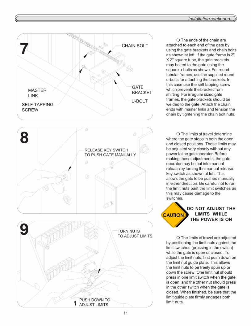
The ends of the chain areattached to each end of the gate byusing the gate brackets and chain boltsas shown at left. If the gate frame is 2"X 2" square tube, the gate bracketsmay bolted to the gate using thesquare u-bolts as shown. For roundtubular frames, use the supplied roundu-bolts for attaching the brackets. Inthis case use the self tapping screwwhich prevents the bracket fromshifting. For irregular sized gateframes, the gate brackets should bewelded to the gate. Attach the chainends with master links and tension thechain by tightening the chain bolt nuts.
The limits of travel determinewhere the gate stops in both the openand closed positions. These limits maybe adjusted very closely without anypower to the gate operator. Beforemaking these adjustments, the gateoperator may be put into manualrelease by turning the manual releasekey switch as shown at left. Thisallows the gate to be pushed manuallyin either direction. Be careful not to runthe limit nuts past the limit switches asthis may cause damage to theswitches.
The limits of travel are adjustedby positioning the limit nuts against thelimit switches (pressing in the switch)while the gate is open or closed. Toadjust the limit nuts, first push down onthe limit nut guide plate. This allowsthe limit nuts to be freely spun up ordown the screw. One limit nut shouldpress in one limit switch when the gateis open, and the other nut should pressin the other switch when the gate isclosed. When finished, be sure that thelimit guide plate firmly engages bothlimit nuts.
DO NOT ADJUST THELIMITS WHILE
THE POWER IS ON
9
7
8
U-BOLT
GATEBRACKET
SELF TAPPING SCREW
MASTER LINK
RELEASE KEY SWITCH TO PUSH GATE MANUALLY
TURN NUTS TO ADJUST LIMITS
PUSH DOWN TO ADJUST LIMITS
CHAIN BOLT

12
Electrical
Before making any electricalconnections be sure that the power isswitched off. If the gate operator is astandard 115 Volt model, run conduitfrom the 115 Volt power source into thegate operator. The gate operator isprovided with a 90 degree flexible conduitfitting for installations where the electricalbox is relatively close. Because of the 90degree fitting, it is generally easier to runthe electrical wires through the flexibleconduit before attaching the conduit.Wiring for other devices such as pushbuttons may also be run at this timeeither in the same conduit or in another.
Make sure that wiring is em-ployed as required by local codes.
If not already done, run three 12gauge wires (hot, neutral, and ground)from the power source, through theconduit and into the gate operator. It iseasiest to run these wires back out of thelarge hole in the operator along with thethree existing wires. This allows theconnections to be made externally andthen later inserted back into the operatorthrough the large hole. Be sure to usewire nuts to secure these connections.Be sure that the grounding wire isconnected to a good earth ground. Makethe connections as follows:
Black to (hot)White to (neutral)Green to (ground)
If the gate operator is a batteryrun model, it is packaged from the factorywith the battery disconnected. Connectthe red wire to the positive batteryterminal and the black wire to thenegative battery terminal. There are wiresprovided for connecting the low voltageburial cable from the float charger to thegate operator. The burial cable may berun through the knock-out in the bottomof the battery enclosure and then con-nected to the two wires provided. Be surethat the positive and negative match thepositive and negative of the charger.
3
1
2

13
Electrical continued...
Connect the other end of theburial cable from the operator to the floatcharger. Be sure to match the positiveand negative terminals of the charger tothe positive and negative terminals of thebattery. Once the connections are made,plug the charger into a 115 Volt outlet. Ifpossible, it is desirable to locate thecharger out of the weather. Let thecharger charge the battery for a couple ofhours before putting into operation.
If the gate operator is solarpowered, no power will need to be runinto the machine. The solar panel is setup to be attached to the gate operatorand extension pipes are provided toelevate the panel up above the operator.While assembling the pipes and attach-ing the panel, run the wires from thepanel through the pipes. The ends of thewires are provided with connectors whichcan simply be plugged in. Turn the panelso that it will get maximum sunlightduring the day. If necessary the panelmay be mounted away from the gateoperator to get it out of the shade andinto more consistent sunlight.
Similarly to the battery run, thesolar operator comes with the batterywires disconnected. For both batteries,connect the black wires to the negativeterminals and the red wires to the positiveterminals. The wires have been labeled tomake these connections easier to do.
6
4
5

14
1 2 3 4
412 HM RADIO
RECEIVER
Electrical continued...ACCESSORY CONNECTIONS - FULL SYSTEMS CAPABILITY
N.O. STOP INPUT: This input functions the sameas the N.C. Stop, with the exception that it requires nor-mally open contacts. These contacts are connected toterminals 9 and 11.
SAFETY INPUT: Any device that is used to openand/or hold open the gate while the gate is in a non-closedposition is a safety input device. The safety input devicemust provide normally open contacts. These contacts areconnected to terminals 4 and 6. This function is especiallyuseful when the auto close timer is being used in preventingthe gate from accidentally closing on a pedestrian orvehicle.
PULSE OPEN INPUT: This input functions similarlyto the standard open input with the exception that it will nothold the gate open if the input remains present. This featurewill add additional security to the gate operator system inthe event that there is a device that is stuck on. Pulse openis found at terminals 6 and 7.
SAFETY NOTES: Controls must be far enough fromthe gate so that the user is prevented from coming in contactwith the gate while operating the controls. Controls intended tobe used to reset an operator after 2 sequential activations ofthe entrapment protection device or devices must be located inthe line of sight of the gate. Outdoor or easily accessiblecontrols shall have a security feature to prevent unauthorizeduse.
OPEN INPUT: Any device that is used to open thegate from a closed position is an open input device. The deviceused must provide normally open contacts. These normallyopen contacts are connected to terminals 5 and 6. These openinput terminals will cause the gate operator to open and/orclose if the timer switch is in the OFF position. If the timerswitch is in the ON position, these open input terminals willcause the gate operator to open and will hold the gate openuntil the input is released and the hold open time has elapsed.
CLOSE INPUT: Any device that is used to close thegate is a close input device. The device used must providenormally open contacts. These normally open contacts areconnected to terminals 9 and 10. These close input terminalswill cause the gate operator to close the gate any time the gateis in a non-closed position and can be used to override thetimer and close the gate prematurely.
N.C. STOP INPUT: Any device that is used to stop thegate operator while it is running in the open or closed directionsis a stop input device. These stop input devices must providenormally closed contacts. To connect these normally closedcontacts, remove the stop jumper from terminals 8 and 9 andthen connect the contacts to these same terminals 8 and 9.
TO AVOID POSSIBLE INJURY ORDAMAGE TO EQUIPMENT DO NOTMAKE ELECTRICAL CONNECTIONSWHILE POWER IS ON

15
Electrical continued... OTHER COMMON ACCESSORIES
NOTE: All open and safety devices must have
normally open contacts. For Devices requiring power, refer to
the specific diagram for that particulardevice.
Be sure to read this entire manual before attempting toperform any type of installation or service to the gate opener.
Once the installation has been completed, this installa-tion and service manual becomes the property of the homeowner or end user and should be given to the new owner at thattime.
For a personal copy of this manual, please contact aLiftMaster.

16
This step is for sensitivityadjustments on the full systems capabil-ity control board. To make adjustments,use a small screw driver to turn theadjustment "pots" clockwise for moresensitivity or counter clockwise for lesssensitivity. There are separate adjust-ments for both the opening and closingdirections of travel and these must bothbe adjusted. Try applying force againstthe gate while it is moving both open andclose to test the setting (Caution: Do notstand directly in the path of the gatewhile doing this). The gate should stop orreverse easily.Caution: Disconnect power whilemaking any adjustments.
With the full systems capabilitycontrol board there is the option of usingthe auto close timer which will close thegate automatically after it has opened. Toturn this feature on, flip the auto closetimer to the on position. To adjust theamount of time it takes for the gate tobegin closing use a small screw driver toturn the adjustment "pot" clockwise formore time (45 sec max) or counterclockwise for less time. It is recom-mended that if the auto close timerfunction is used, that there be additionalsafety equipment installed to prevent thegate from closing into a vehicle orpedestrian.Caution: Disconnect power whilemaking adjustments.
If the gate seems to be function-ing in reverse, the right/left side operationswitch may need to be flipped (fullsystem capability only). One way toknow if the operator is working in reverseis to try the sensitivity. If pressure isapplied to the gate while it is closing, itshould reverse and go open. If pressure isapplied to the gate while it is opening, itshould stop and remain stopped untilactivated again. If the gate operatorresponds differently than this, flip theright/left side operation switch. If the autoclose timer function is turned on, thisprovides another way of knowing if theoperator is working in reverse. If when thegate gets closed, the operator automati-cally opens, the right/left side switch mayneed to be flipped the other way.
Fine Tuning
3FULL SYSTEMS CAPABILITY
2
1

17
Master/Second Wiring
SL 505 Full Systems Capability
NOTE:1) The timer switch on the Secondcircuit board must be OFF at alltimes.
Master Second
Connect 115 Volts AC to each SL505 gate operator. Connect the four Master/Second wires from the master circuit boardto the second circuit board as shown below. Any operator can be used as either a master or a second. Accessories can beconnected to the master or second operator.
Switch the Auto Close Timer switch to the OFF position on the second circuit board. The Auto Close Timer switch on themaster circuit board may be switched either ON if the timer function will be used or OFF if the timer function will not be usedbut the second timer must always be switched OFF.
If the chain is wrapped around the sprockets in the same manner on each operator (both chains under or both chains overthe drive sprocket) set the Right/Left Side Operation switch on the master circuit board to be the opposite of the way it is seton the second circuit board. If the chain wrapped around the drive sprocket on the master operator is the opposite of the wayit is wrapped around on the second operator then set the Right/Left Side Operation switches the same on both operators.The Right/Left Side operation switch is located on the circuit board. If the operators are working backwards, the Right/LeftSide Operation switches on both operators must be switched. The simplest way to know if the operators are working back-wards is to turn the Auto Close Timer switch on the master circuit board to ON and see whether the timer works when thegate is open or closed. The timer should work only when the gate is open. Another way to know if the operators are workingbackwards is to try the gate sensitivity by applying pressure against the gate while the gate is opening or closing. If pressureis applied while the gate is opening it should stop. If pressure is applied while the gate is closing it should reverse and goopen. If the gate responds to pressure in a way that is opposite of this then switch the Right/Left Side Operation switch onboth operators.

18
Wiring Diagrams SL 505 Full Systems Capability, 115 VAC
412 HM RADIO
RECEIVER
see pge 14for Radio WringSpecifications

19
Wiring Diagrams SL 505 Full Systems Capability, Battery RunBREAKER15 AMP
412 HM RADIO
RECEIVER
see pge 14for Radio WringSpecifications

20
BREAKER15 AMP
412 HM RADIO
RECEIVER
see pge 14for Radio WringSpecifications
Wiring Diagrams SL 505 Full Systems Capability, Solar Powered

21
See reversing edge sensorinstructions for the exact placement ofthe reversing edge contact sensors.
One or more contact sensorsshall be located at the leading edge,trailing edge, and post mounted bothinside and outside of a vehicular horizon-tal slide gate. When the contact sensoris hard wired, it shall be located and itswiring arranged so that the communica-tion between the sensor and the gateoperator is not subjected to mechanicaldamage.
With full systems capabilitycontrol boards, the edge sensor isconnected to terminals 24 and 26 asshown at left in figure 2.
The gate operator is providedwith two safety warning placards. Theplacards are to be installed on each sideof the gate where they are plainly visible.The placards may be mounted usingsheet metal screws through the six holesprovided on each placard.
All warning signs and placardsmust be installed where visible in thearea of the gate.
22222
11111
Safety Edge and Safety Warning Placard Installation

22
If it is desired that the drivewayilluminate when the gate is activated, a lightdelay timer may be installed. The light delaytimer will switch power on to the light for twominutes, then shut power back off. The timerrelay is capable of switching up to 10 Ampswhich will handle most flood or spot lightsavailable. A general hook-up diagram for thelight and timer is shown at left.
The standard auto close timer builtinto the circuit board can be adjusted tobetween 0 and 45 seconds. Some installa-tions may require that the gate must stayopen for more than 45 seconds before itautomatically closes. The extended autoclose timer may be hooked up as shown atleft. This optional timer can be adjusted toautomatically close the gate after the gatehas been open between 1 and 100 minutes.The extended timer will add time onto theauto close timer already on the board. Formore control, reduce the timer adjustment onthe main control board to zero seconds andmake all adjustments with the extended autoclose timer knob.
For added safety, a warning alarmmay be installed in the gate operator to giveaudible warning that the gate is in motion.This will in some cases give extra time to getout of the way of the moving gate. Thewarning alarm is an ear piercing 120 decibel,dual tone, piezo siren that operates on 12Volt DC. To install the alarm, mount the sirennext to the circuit board and connect thepositive wire to terminal 12 (12VDC). Connectthe negative wire to limit switch 1 NC or limitswitch 2 NC for the alarm to sound in theopen or closed directions. Contact themanufacturer for connecting the alarm tosound in both directions. If the alarm is tooloud, the sound may be partially muffled byapplying tape over the two holes where thesound comes out.
Options
22222
33333
11111

23
Gate Hardware LocatorOptions Continued...

24
Maintenance and Safety
The SL 505 is designed to be MAINTENANCE FREE. However,for optimum performance and safety, the following maintenanceprocedures should be taken.
IMPORTANT SAFETY INSTRUCTIONS
WARNING - To reduce the risk of injury or death:
1) READ AND FOLLOW ALL INSTRUCTIONS
2) Never let children operate or play with gate controls. Keep the remote control away from children.
3) Always keep people and objects away from the gate. NO ONE SHOULD CROSS THE PATH OF THE MOVING GATE.
4) Test the gate operator monthly. The gate MUST reverse on contact with a rigid object or stop when an object activatesthe non-contact sensors. After adjusting the force or the limit of travel, re-test the gate operator. Failure to adjust and re-testthe gate operator properly can increase the risk of injury or death.
5) Use the emergency release only when the gate is not moving.
6) KEEP GATES PROPERLY MAINTAINED. Read the owner's manual. Have a qualified service person make repairs togate hardware.
7) The entrance is for vehicles only. Pedestrians must use separate entrance.
8) SAVE THESE INSTRUCTIONS.
Gate Sensitivity AdjustmentsThe most important thing to maintain on any gate is the safety equipment. As the gate becomes
older the amount of force necessary to move the gate will vary. When this happens, the gate sensitivityadjustments may need to be readjusted. Check to see whether the sensitivity may need adjustment atleast once a month. Actuate the gate a few times and observe the amount of force that is needed to stop orreverse the gate in both directions. This can be done very easily by standing beside the gate and applyingpressure with your hands against the gate while it is moving. Do not stand directly in the path of thegate while doing this experiment. The gate should stop or reverse relatively easy. If it does not stop orreverse easily or does not stop or reverse at all, make adjustments as shown on page 17 of Fine Tuning.
Control DevicesFrom time to time check to see whether all of the control devices that are connected to the
operator are functioning. This is especially important of anything that was installed in regards to safety. Gate
Having a well maintained gate will ensure that the operator runs smoothly and safely. Occasionallyinspect the chain to see whether it is well lubricated and oil the chain if necessary. Use CHAIN ANDCABLE LUBE for best results (Available from the manufacturer). Check the wheels and grease them ifneeded. Check the guide rollers and spray oil on their bearings. Check whether the gate appears to beoperating at normal speed to determine if the gate operator may be working harder than usual to overcomefriction from damaged bearings.

25
Transmitter Does Not WorkCheck the battery inside of the transmitter and/or try another transmitter. Check the open push buttons or open
switches if any are used. A stuck push button or any other stuck opening device connected to terminals 4 and 5 will causethe operator to lock up. Disconnect opening devices one at a time if necessary to determine which opening devices if anyare stuck. Look for stuck transmitters. A stuck transmitter may cause other transmitters to malfunction. Make sure thereis power (10 to 16 VDC) to the receiver on terminals 6 and 7 and make sure that the circuit breaker button is pressed in. Ifa click is heard while the transmitter is being pressed and there is no response from the operator, check all receiverconnections. (See page 14.) If there is still no response, see GATE WILL NOT OPEN OR CLOSE on this page.
Gate Travels Too Far Or Not Far EnoughAdjust the gate sensitivity (see page 17). If the gate sensitivity adjustment is too sensitive, the gate will reverse or
stop in mid-travel. It may be necessary to lubricate any mechanical parts on the gate including wheels and rollers andclean the track of any debris. Check the stop push buttons, if any are used. Adjust the limits of travel (see page 11).This adjustment may change slightly as the chain stretches due to normal wear and it may change dramatically if the chainhas been re-tightened or the limit plate is accidentally left not engaged with the limit nuts. If a limit nut has traveled past alimit switch, check the limit switch and all limit switch connections. (See pages 22, 23 and 24.)
Gate Begins To Open Or Close, Then ReversesA typical reason for this symptom is a stuck transmitter. A common reason for this symptom is a faulty open
push button or key switch. Disconnect opening devices one at a time if necessary to determine which opening device ifany is stuck. Adjust the gate sensitivity (see page 17). If the gate sensitivity adjustment is too sensitive, the gate willreverse or stop in mid-travel. It may be necessary to lubricate any mechanical parts on the gate including wheels androllers and clean the track of any debris.
Gate Will Not Open Or CloseTest the operator to find out whether the open input devices are functioning by following these steps. If you are
using a remote control to open your gate, try another remote control or try using a push button if there is one installed. Ifyou are using a push button try using another push button or a remote control. If there is no push button installed you mayoperate your gate by connecting a jumper wire to terminal 4 and touching it to terminal 5. If the remote controls are notworking , see TRANSMITTER DOES NOT WORK on this page. Check the manual release key switch to make sure it is inthe operate (vertical) position. Check the open push buttons or open key switches if any are used. A stuck push button orany other opening device connected to terminals 4 and 5 will cause other open input devices to malfunction. Disconnectopening devices one at a time if necessary to determine which opening device if any is stuck. Check the circuit breakerbutton. If the circuit breaker is tripped, press it back in. Make sure there is power (10 to 16 VDC) on terminals 6 and 7.
The Gate Will Not Reverse When It Meets An ObstructionAdjust the gate sensitivity (see page 17). It needs to be adjusted for more sensitivity. This is done by turning the
gate sensitivity adjustment counter-clockwise for more sensitivity.
Troubleshooting

26
Troubleshooting continued...
Explanation Of Visual Feedback LEDsThe SL 505 Full Systems Capability circuit board has been equipped with Visual Feedback LEDs to simplify
installation and troubleshooting. These are small lights which are located directly beside the input terminals. These LEDsgive visual information to the installer or service technician indicating what commands are going into the circuit board fromdevices such as limit switches or from peripheral devices such as radio receivers or safety loops. There are also two LEDswhich show output to the motor for both the opening and closing directions.
INPUT:Limit Switch 1: This LED indicates that one of the normally open limit switches is pressed in and the gate is in the openposition.Limit Switch 2: This LED indicates that one of the normally open limit switches is pressed in and the gate is in the closedposition.Safety: This LED indicates that there is a closed contact between safety input terminal 4 and common.Open: This LED indicates that there is a closed contact between open input terminal 5 and common.Pulse Open: This LED indicates that there is a closed contact between Pulse Open input terminal 7 and common. This LEDalso stays illuminated while the gate is opening.N.C. Stop: This LED indicates that there is a closed contact between stop input terminal 9 and common. Under normaloperating conditions this LED must be in the on condition in order for the system to function.Close: This LED indicates that there is a closed contact between close input terminal 10 and common. This LED also staysilluminated while the gate is closing.
Transmitter Does Not Work Check the battery inside of the transmitter and/or try another transmitter. Check to see which LEDs are
illuminated on the circuit board. For normal operating conditions the only LEDs that should be illuminated are the stop inputat terminal 9 and Limit Switch 1 input if the gate is in the fully open position or Limit Switch 2 input if the gate is in the fullyclosed position. If any of the input LEDs are illuminated on terminals 4, 5, 7 or 10, disconnect wires from that inputterminal that is illuminated until the LED is extinguished to determine which input device may be stuck in an on condition.
If it is the radio receiver that appears to be stuck in an on condition, check all transmitters to see if any of them are stuckon. Make sure that there is power (10 to 16 VDC) to the receiver on terminals 8 and 12 and make sure that the circuitbreaker button is pressed in and that the motor fuse is not blown. If a click is heard while the transmitter is being pressedand there is no response from the operator, check all receiver connections. (See page 15.) If there is still no response,see GATE WILL NOT OPEN OR CLOSE on next page.
Gate Travels Too Far Or Not Far Enough Adjust the gate sensitivity (See page 17). If the gate sensitivity adjustment is too sensitive, the gate may stop in
mid-travel. It may be necessary to lubricate any mechanical parts on the gate such as wheels and clean the gate track ofany debris. Check the limit switch input LEDs on terminals 1 and 3 to see if either one is illuminated. If one of the limitswitch input LEDs is illuminated and the gate has traveled too far or not far enough, this indicates that the limits of travel mayneed adjustment. Adjust the limits of travel (See page 11). This adjustment may change slightly as the chain stretches dueto normal wear and it may change dramatically if the limit plate is accidentally left not engaged with the limit nuts. If thelimit nut has traveled past a limit switch, check the limit switch and all limit switch connections. (See page 20 or 21). Watch the stop input LED on terminal 9 while the gate operator is running and see if the LED flickers or extinguishes. Thismay indicate a faulty stop input device or a poor connection between the stop input terminal 9 and common. If the stopinput LED on terminal 9 flickers or extinguishes, check all connections to the stop input device and/or replace the faultydevice.
Full Systems Capability

27
Troubleshooting continued...
Gate Begins To Open Or Close, Then Stops Or Reverses Adjust the gate sensitivity (See page 17). If the gate sensitivity adjustment is too sensitive, the gate may stop in
mid-travel or reverse. It may be necessary to lubricate any mechanical parts on the gate such as wheels and clean thegate track of any debris. Watch the input LEDs on terminals 4, 5, 7 and 10 while the gate operator is running to see if anyof the LEDs flicker or illuminate. If there is an input LED that flickers or illuminates while the gate is running, disconnectthe wires one at a time from that input terminal until the LED does not flicker or illuminate to determine which input devicemay be activating. If it is the radio receiver that appears to be stuck in the on condition, check all transmitters to see ifany of them may be stuck on. A stuck transmitter may cause the gate operator to reverse.
Gate Will Not Open Or CloseTest the operator to find out whether the open input devices are functioning by following these steps. If a remote
control is being used to open the gate, try another remote control or try using a push button if there is one installed. If apush button is being used try using another push button or a remote control. If there is no push button installed the gatemay be operated by connecting a jumper wire to terminal 6 and momentarily touching it to terminal 5 or 7. If the remotecontrols are not working, see TRANSMITTER DOES NOT WORK on the previous page. Check the motor fuse and replaceit if necessary. Check to see which LEDs are illuminated on the circuit board. For normal operating conditions the onlyLEDs that should be illuminated are the stop input at terminal 9 and Limit Switch 1 input if the gate is in the fully openposition or Limit Switch 2 input if the gate is in the fully closed position. If any of the input LEDs are illuminated onterminals 4, 5, 7 or 10, disconnect wires from that input terminal that is illuminated until the LED is extinguished todetermine which input device if any may be stuck. If the stop input LED on terminal 9 is not illuminated, check the stopinput device if any are installed and all connections to the device. If no stop input device is installed make sure that there is ajumper between terminals 8 and 9 and that it is securely fastened. Check the circuit breaker button. If the circuit breakeris tripped, press it back in. Make sure there is power to the circuit board on terminals 13 and 15.
The Gate Will Not Stop Or Reverse When It Meets An Obstruction Adjust the gate sensitivity. The operator may need to be adjusted for more sensitivity. This is done by turning the
open and close gate sensitivity adjustments clockwise for more sensitivity. (See page 17).
Gate Will Not Stay Closed Make sure that the Right/Left side operation switch is in the correct position (See page 18). If the Right/Left side
operation switch is in the incorrect position, the auto close timer feature may be working in reverse and telling the gateoperator to open after the auto close time has elapsed. Check to see if any input LEDs on terminals 4, 5 or 7 flicker orilluminate when the gate gets to the closed position. If any of the input LEDs flicker or illuminate on terminals 4, 5, or 7,disconnect wires from that input terminal that is illuminated until the LED is extinguished to determine which input device ifany may be activating.
Timer Will Not Close The Gate Make sure that the Right/Left side operation switch is in the correct position (See page 18). If the Right/Left side
operation switch is in the incorrect position, the auto close timer feature may be working in reverse and telling the gateoperator to open instead of close after the auto close time has elapsed. Make sure the auto close timer switch is in theON position (See page 17). The auto close timer switch is located on the top corner of the circuit board. Make sure thatthe radio receiver, push button or other open input device is connected to open input terminals 5 and 6. The timer may notwork if any of these devices are connected to pulse open input terminals 6 and 7. Adjust the amount of auto close time(See page 17). The auto close time may be set too high and is simply taking a long time to close. Do not continue pressingthe remote control or other open or safety input devices because each time an open or a safety input is given the timer willreset and begin counting over.
Operator Runs In Only One Direction Check to see which LEDs are illuminated on the circuit board. For normal operating conditions the only LEDs that
should be illuminated are the stop input at terminal 9 and Limit Switch 1 input if the gate is in the fully open position or LimitSwitch 2 input if the gate is in the fully closed position. If any of the input LEDs are illuminated on terminals 4, 5, 7 or 10,disconnect wires from that input terminal that is illuminated until the LED is extinguished to determine which input devicemay be stuck.

28
WARNINGTo reduce the risk of injury use
this operator only with a sliding gate that isno larger than 20 ft in lengthand no heavier than 375 lbs.
2003, The Chamberlain Group, Inc. All rights Reserved
01-40006A
WHEN ORDERING REPAIR PARTSPLEASE SUPPLY THE FOLLOWING INFORMATION:PART NUMBER DESCRIPTION MODEL NUMBER
ADDRESS ORDER TO:THE CHAMBERLAIN GROUP, INC.TECHNICAL SUPPORT CENTER
6020 South Country Club RdTucson, AZ 85706
HOW TO ORDER REPAIR PARTSOUR LARGE SERVICE ORGANIZATION SPANS AMERICA.
INSTALLATION AND SERVICE INFORMATIONARE AVAILABLE 6 DAYS A WEEK
CALL OUR TOLL FREE NUMBER - 1-800-528-2806MONDAY Through FRIDAY 5:00 a.m. TO 6:00 p.m. (MST)
SATURDAY 7:00 a.m. TO 3:30 p.m. (MST)WWW.LIFTMASTER.COM
Be sure to read this entire manual before attempting to perform any type of installation or service to the gate opener.After installation, this manual becomes property of the home owner/end user and should be given to him/her at that time.
For a personal copy of this manual, please contact a LiftMaster distributor.