owner's manual of console -...
TRANSCRIPT
Owner's Manual
NOTE TO EQUIPMENT OWNER:Please read this Owner’s Information Manual carefully before installing and using this applianceand keep this manual for future reference.
For your convenience, please record the model and serial numbers of your new equipment in thespaces provided. This information, along with the installation data and dealer contact information,will be helpful should your system require maintenance or service.
UNIT INFORMATION
Model # ___________________________________
Serial # ___________________________________
INSTALLATION INFORMATION
Date Installed _____________________________
DEALERSHIP CONTACT INFORMATION
Company Name: _________________________________
Address:_________________________________________
________________________________________________
Phone Number:__________________________________
Technician Name:_________________________________
________________________________________________
40MB*FFloor Console Ductless Split SystemSizes 09 to 12
TABLE OF CONTENTSPAGE
A NOTE ABOUT SAFETY. . . . . . . . . . . . . . . . . . . . . . . . . . . . . . . . . . . . . . . . . . . . . . . . . . . . . . . . . . . . . . . . . . . . . . . . . . . . . . . . . . . 2
MODEL NUMBER NOMENCLATURE . . . . . . . . . . . . . . . . . . . . . . . . . . . . . . . . . . . . . . . . . . . . . . . . . . . . . . . . . . . . . . . . . . . . . . . 2
GENERAL . . . . . . . . . . . . . . . . . . . . . . . . . . . . . . . . . . . . . . . . . . . . . . . . . . . . . . . . . . . . . . . . . . . . . . . . . . . . . . . . . . . . . . . . . . . . . . . . 3
IMPORTANT SAFETY INFORMATION . . . . . . . . . . . . . . . . . . . . . . . . . . . . . . . . . . . . . . . . . . . . . . . . . . . . . . . . . . . . . . . . . . . . . . 4
PARTS NAMES . . . . . . . . . . . . . . . . . . . . . . . . . . . . . . . . . . . . . . . . . . . . . . . . . . . . . . . . . . . . . . . . . . . . . . . . . . . . . . . . . . . . . . . . . . . 5
REMOTE CONTROL OPERATION . . . . . . . . . . . . . . . . . . . . . . . . . . . . . . . . . . . . . . . . . . . . . . . . . . . . . . . . . . . . . . . . . . . . . . . . . . 6
REMOTE CONTROL FUNCTIONS . . . . . . . . . . . . . . . . . . . . . . . . . . . . . . . . . . . . . . . . . . . . . . . . . . . . . . . . . . . . . . . . . . . . . . . . . . 7
USING THE REMOTE CONTROL . . . . . . . . . . . . . . . . . . . . . . . . . . . . . . . . . . . . . . . . . . . . . . . . . . . . . . . . . . . . . . . . . . . . . . . . . . . 10
AIR CONDITIONER OPERATIONS AND PERFORMANCE . . . . . . . . . . . . . . . . . . . . . . . . . . . . . . . . . . . . . . . . . . . . . . . . . . . . . 19
HINTS FOR ECONOMICAL OPERATION . . . . . . . . . . . . . . . . . . . . . . . . . . . . . . . . . . . . . . . . . . . . . . . . . . . . . . . . . . . . . . . . . . . . 19
AIR FLOW SELECTION . . . . . . . . . . . . . . . . . . . . . . . . . . . . . . . . . . . . . . . . . . . . . . . . . . . . . . . . . . . . . . . . . . . . . . . . . . . . . . . . . . . 20
MAINTENANCE . . . . . . . . . . . . . . . . . . . . . . . . . . . . . . . . . . . . . . . . . . . . . . . . . . . . . . . . . . . . . . . . . . . . . . . . . . . . . . . . . . . . . . . . . . 20
FOLLOWING SYMPTOMS ARE NOT AIR CONDITIONER TROUBLES . . . . . . . . . . . . . . . . . . . . . . . . . . . . . . . . . . . . . . . . . . 22
TROUBLESHOOTING . . . . . . . . . . . . . . . . . . . . . . . . . . . . . . . . . . . . . . . . . . . . . . . . . . . . . . . . . . . . . . . . . . . . . . . . . . . . . . . . . . . . . 22

A NOTE ABOUT SAFETYAny time you see this symbol in manuals, instructions and onthe unit, be aware of the potential for personal injury. There arethree levels of precaution:
DANGER identifies the most serious hazards which will result insevere personal injury or death.
WARNING signifies hazards that could result in personal injury ordeath.
CAUTION is used to identify unsafe practices which could resultin minor personal injury or product and property damage.
NOTE is used to highlight suggestions which will result inenhanced installation, reliability, or operation.
PERSONAL INJURY, DEATH AND / OR PROPERTYDAMAGE HAZARD
Failure to follow this warning could result in personal injury,death or property damage.
Improper installation, adjustment, alteration, service,maintenance, or use can cause explosion, fire, electrical shock,or other conditions which may cause personal injury orproperty damage. Consult a qualified installer, service agency,or your distributor or branch for information or assistance. Thequalified installer or service agency must usefactory--authorized kits or accessories when modifying thisproduct.
Read and follow all instructions and warnings, including labelsshipped with or attached to unit before operating your new airconditioner.
! WARNING
GENERALThe high wall fan coil unit provides quiet, maximum comfort. Inaddition to cooling and/.IMPORTANT: The high wall fan coil unit should be installed byauthorized personnel only; using approved tubing and accessories.If technical assistance, service or repair is needed, contact theinstaller.The high wall fan coil unit can be set up and operated from theremote control (provided). If the remote is misplaced, the systemcan be operated from the “Auto” setting on the unit.
Operating Mofive operating modes.
S Fan only
S Auto
S Heating (heat pump models only)
S Cooling
S Dehumidification (DRY)
Fan OnlyIn Fan Only mode, the system filters and circulates room airwithout changing room air temperature.
AutoIn Auto mode, the system will automatically cool or heat the roomaccording to the user--selected set point.
HeatingIn Heating mode, the system heats and filters room air.
CoolingIn Cooling mode, the system cools, dries and filters room air.
Dehumidification (DRY)In Dehumidification mode, the system dries, filters and slightlycools room air temperature. This mode prioritizes airdehumidification but it does not take the place of a dehumidifier.
Remote ControlThe remote control transmits commands to set up and operate thesystem. The control has a window display panel that shows thecurrent system status. The control can be secured to a surfacewhen used with the mounting bracket provided.
The first two digits indicate the equipment type.40 = Indoor unit; 38 = Outdoor uni
Digit 5 indicates the system's type:C = Cooling only;Q = Heat pump
Maximum Number of fan coil units connected to the outdoor unitB = 1:1
Digits 7, 8 indicate the system's capacity in 1000 BTU/HrExample: 09 = 9000 BTU/Hr
Digit 9 - Indoor Fan Coil Unit TypeB = High-WallC = CassetteD = DuctedF = ConsoleG = UnderceilingH = High Wall Color Variation- = Outdoor
Digit 12 indicates voltage1 = 115/l/603 = 208-230-1-60Hz
40 MA Q B 09 B -- 3
Digits 10, 11 - blank
Digits 3 and 4 represent the model
Unit Tons Unit Btuh
0.75 9,00012,000
208/230-1 40MBQB09F--340MBQB12F--3208/230-11
Indoor ModelNumber
Volt- Ph @60Hz
Model Numbers
2
Model number Nomenclature

INDOOR UNIT
OUTDOOR UNIT
123456
789
Display panel
Connecting pipeAir inlet
Drain pipe
Air outletInstallation partRemote controller
Fig.1
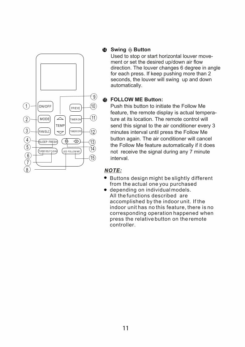
All the pictures in this manual are for illustration purpose only. They may differ slightly from the air conditioner you purchased (depending on model).
NOTE
Air flow louver (at air outlet)Air inlet (with air filter in it)
INDOOR UNIT OUTDOOR UNIT
78
1
9
6
71
3
4
2
5
3
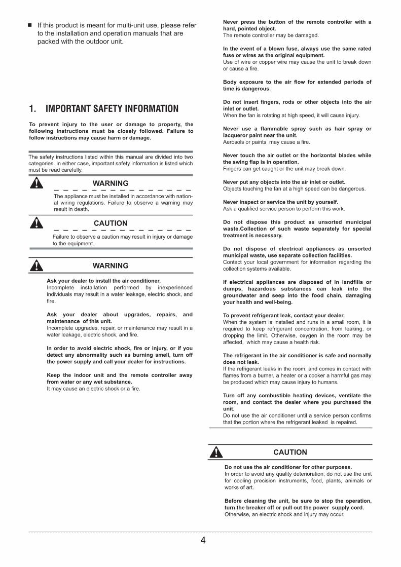
1. IMPORTANT SAFETY INFORMATION
To prevent injury to the user or damage to property, the following instructions must be closely followed. Failure to follow instructions may cause harm or damage.
Ask your dealer to install the air conditioner. Incomplete installation performed by inexperienced individuals may result in a water leakage, electric shock, and fire.
Ask your dealer about upgrades, repairs, and maintenance of this unit. Incomplete upgrades, repair, or maintenance may result in a water leakage, electric shock, and fire.
In order to avoid electric shock, fire or injury, or if you detect any abnormality such as burning smell, turn off the power supply and call your dealer for instructions.
Keep the indoor unit and the remote controller away from water or any wet substance. It may cause an electric shock or a fire.
Do not use the air conditioner for other purposes. In order to avoid any quality deterioration, do not use the unit for cooling precision instruments, food, plants, animals or works of art.
Before cleaning the unit, be sure to stop the operation, turn the breaker off or pull out the power supply cord. Otherwise, an electric shock and injury may occur.
Never press the button of the remote controller with a hard, pointed object. The remote controller may be damaged.
In the event of a blown fuse, always use the same rated fuse or wires as the original equipment. Use of wire or copper wire may cause the unit to break down or cause a fire.
Body exposure to the air flow for extended periods of time is dangerous.
Do not insert fingers, rods or other objects into the air inlet or outlet. When the fan is rotating at high speed, it will cause injury.
Never use a flammable spray such as hair spray or lacqueror paint near the unit. Aerosols or paints may cause a fire.
Never touch the air outlet or the horizontal blades while the swing flap is in operation. Fingers can get caught or the unit may break down.
Never put any objects into the air inlet or outlet. Objects touching the fan at a high speed can be dangerous.
Never inspect or service the unit by yourself. Ask a qualified service person to perform this work.
Do not dispose this product as unsorted municipal waste.Collection of such waste separately for special treatment is necessary.
Do not dispose of electrical appliances as unsorted municipal waste, use separate collection facilities.Contact your local government for information regarding the collection systems available.
If electrical appliances are disposed of in landfills or dumps, hazardous substances can leak into the groundwater and seep into the food chain, damaging your health and well-being.
To prevent refrigerant leak, contact your dealer. When the system is installed and runs in a small room, it is required to keep refrigerant concentration, from leaking, or dropping the limit. Otherwise, oxygen in the room may be affected, which may cause a health risk.
The refrigerant in the air conditioner is safe and normally does not leak. If the refrigerant leaks in the room, and comes in contact with flames from a burner, a heater or a cooker a harmful gas may be produced which may cause injury to humans.
Turn off any combustible heating devices, ventilate the room, and contact the dealer where you purchased the unit. Do not use the air conditioner until a service person confirms that the portion where the refrigerant leaked is repaired.
The safety instructions listed within this manual are divided into two categories. In either case, important safety information is listed which must be read carefully.
The appliance must be installed in accordance with nation-al wiring regulations. Failure to observe a warning may result in death.
Failure to observe a caution may result in injury or damage to the equipment.
CAUTION
CAUTION
WARNING
WARNING
If this product is meant for multi-unit use, please refer to the installation and operation manuals that are packed with the outdoor unit.
4
This appliance is not intended for use by persons (including children) with reduced physical, sensory or mental capabilities, or lack of experience and knowledge, unless they have been given supervision or instruction concerning use of the appliance by a person responsible for their safety.
Children should be supervised to ensure that they do not play with the appliance.
If the supply cord is damaged, it must be replaced by the manufacturer, its service agent or similarly qualified persons in order to avoid a hazard.
Do not operate your air conditioner in a wet room such as a bathroom or laundry room.
In order to avoid electric shock or fire, make sure that an earth leak detector is installed.
Be sure the air conditioner is grounded. In order to avoid electric shock, make sure that the unit is grounded and that the earth wire is not connected to the gas or water pipe, lightning conductor or telephone earth wire.
In order to avoid injury, do not remove the fan guard of the outdoor unit.
Do not operate the air conditioner with a wet hand. An electric shock may occur.
Do not touch the heat exchanger fins. The fins are sharp and touching them could result in injury.
Do not place items which might be damaged by moisture under the indoor unit. Condensation may form if the humidity is above 80%, the drain outlet is blocked or the filter is polluted.
After a long use, check the unit stand and fitting for damage. If damaged, the unit may fall and result in injury.
To avoid oxygen deficiency, ventilate the room sufficiently if equipment with a burner is used together with the air conditioner.
Arrange the drain hose to ensure smooth drainage.Poor drainage may cause water damage to the building, furniture etc.
Never touch the internal parts of the controller. Do not remove the front panel. Some internal parts are dangerous to touch, and damage to the unit may occur.
Never expose little children, plants or animals directly to the air flow. Injury to children, pets, or damage to plants may occur if exposed to the unit's direct air flow.
Do not allow a child to mount the outdoor unit and avoid placing objects on it. Falling or tumbling of the unit may result in injury.
Do not operate the air conditioner when using a room fumigation - type insecticide. Failure to observe the safety precautions could cause the chemicals to become deposited in the unit, which could endanger the health of those who are hypersensitive to chemicals.
Do not place appliances which produce open flames in places exposed to the unit's air flow or under the indoor unit. Doing so may cause incomplete combuston or deformation of the unit due to the heat.
Do not install the air conditioner any where flammable gas may leak. If the gas leaks out and remains near the air conditioner, a fire may occur.
The appliance is not intended for use by young children or infirm ed persons without supervision. This appliance can be used by children aged from 8 years and above and persons with reduced physical, sensory or mental capabilities or lack of experience and knowledge if they have been given supervision or instruction concerning use safe of the appliance and understand the hazards involved. Children shall not play with the appliance. Cleaning and user maintenance shall not be performed by children without supervision.
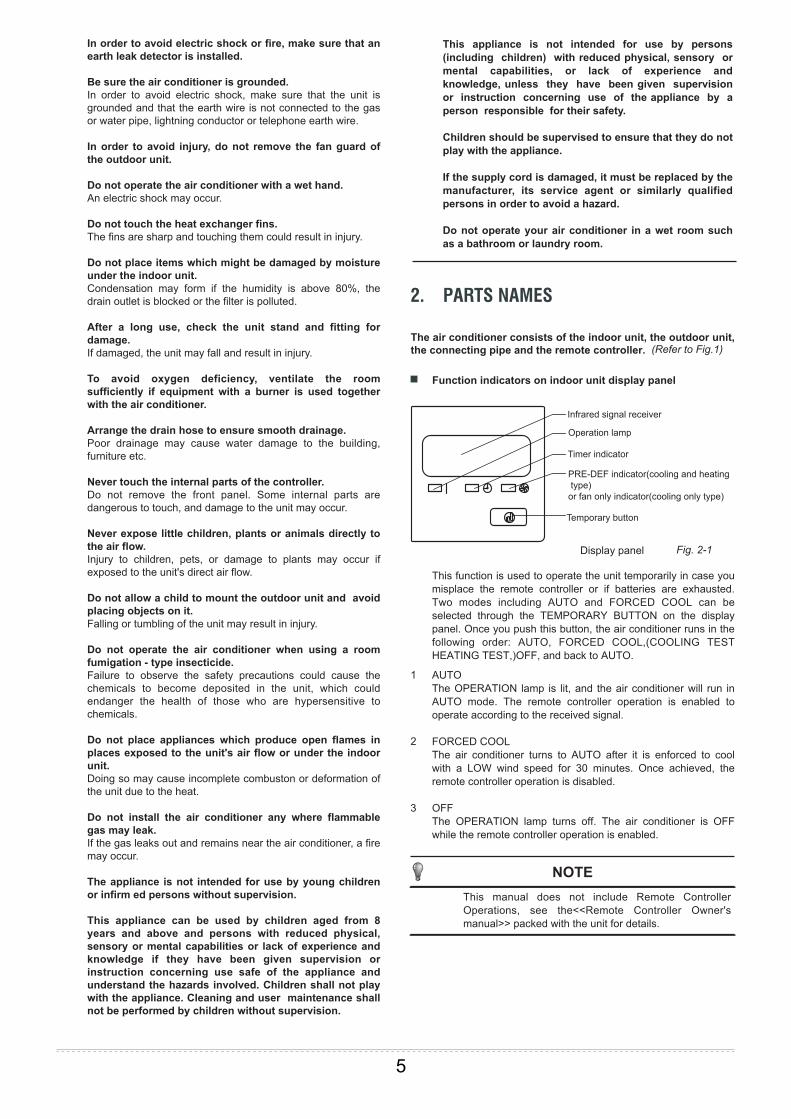
2. PARTS NAMES
The air conditioner consists of the indoor unit, the outdoor unit, the connecting pipe and the remote controller. (Refer to Fig.1)
Function indicators on indoor unit display panel
PRE-DEF indicator(cooling and heating type) or fan only indicator(cooling only type)
Infrared signal receiver
Operation lamp
Timer indicator
Temporary button
This manual does not include Remote Controller Operations, see the<<Remote Controller Owner's manual>> packed with the unit for details.
AUTOThe OPERATION lamp is lit, and the air conditioner will run in AUTO mode. The remote controller operation is enabled to operate according to the received signal.
FORCED COOLThe air conditioner turns to AUTO after it is enforced to cool with a LOW wind speed for 30 minutes. Once achieved, the remote controller operation is disabled.
OFFThe OPERATION lamp turns off. The air conditioner is OFF while the remote controller operation is enabled.
1
2
3
Display panel Fig. 2-1
This function is used to operate the unit temporarily in case you misplace the remote controller or if batteries are exhausted. Two modes including AUTO and FORCED COOL can be selected through the TEMPORARY BUTTON on the display panel. Once you push this button, the air conditioner runs in the following order: AUTO, FORCED COOL,(COOLING TEST HEATING TEST,)OFF, and back to AUTO.
NOTE
5

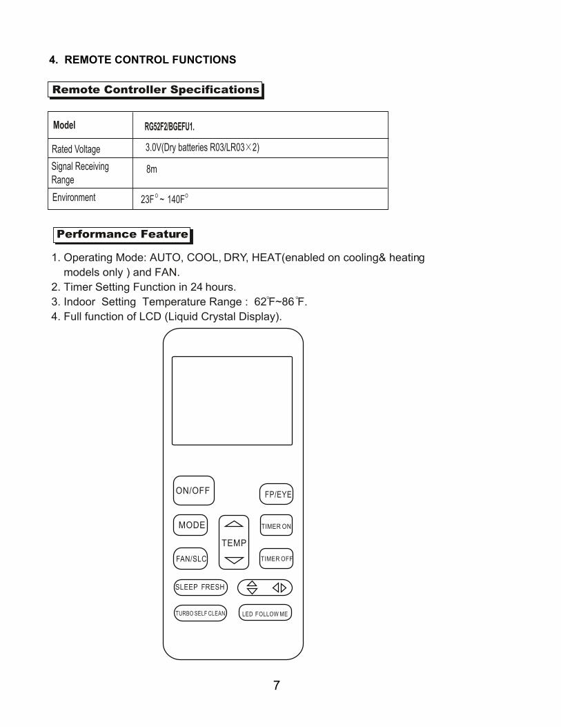
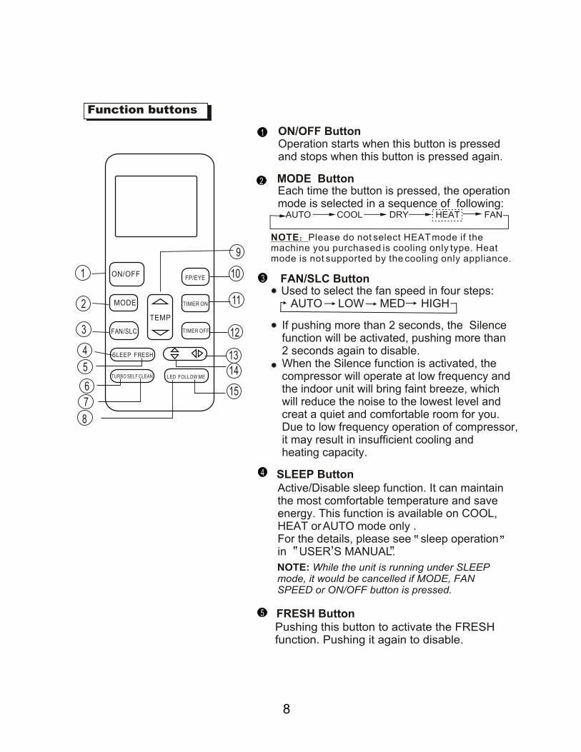
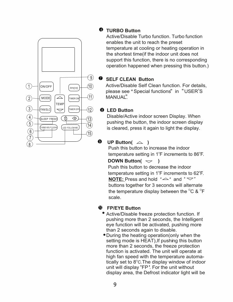
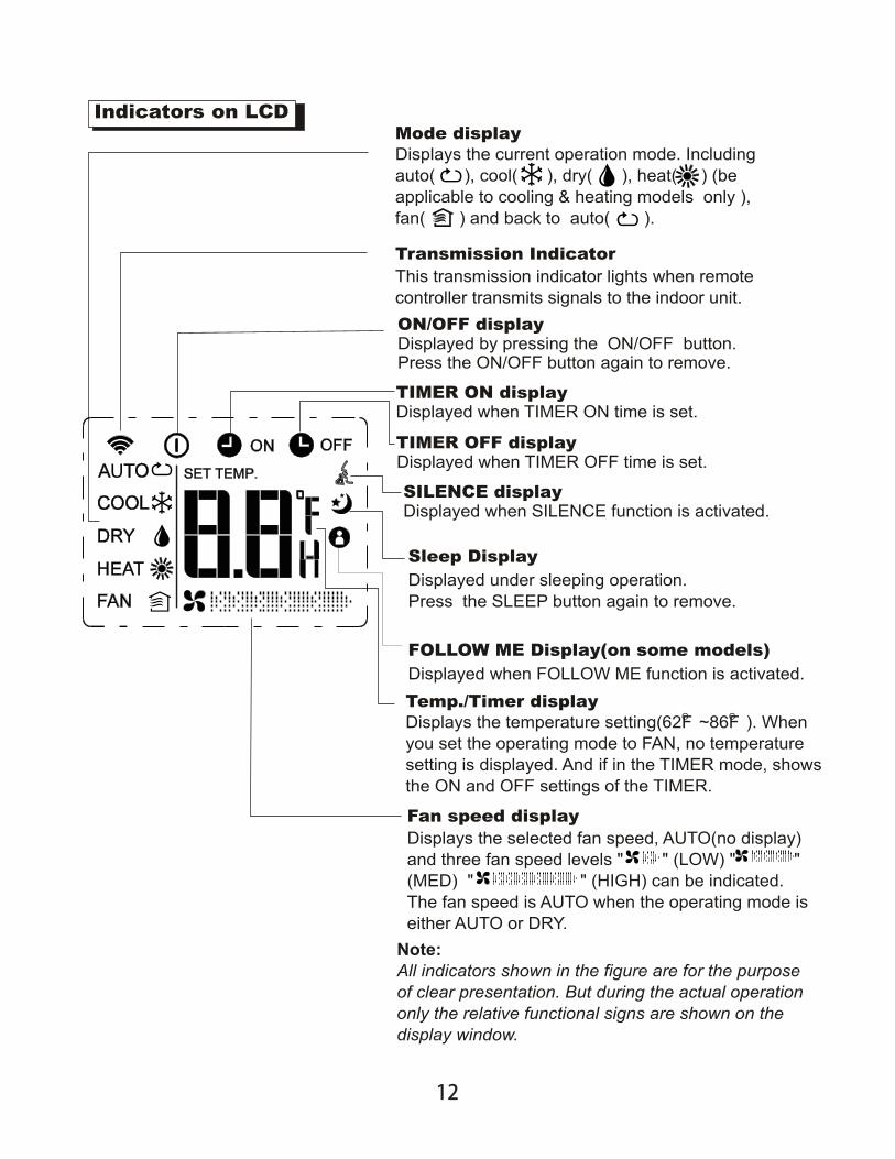
4. REMOTE CONTROL FUNCTIONS
7
8
9
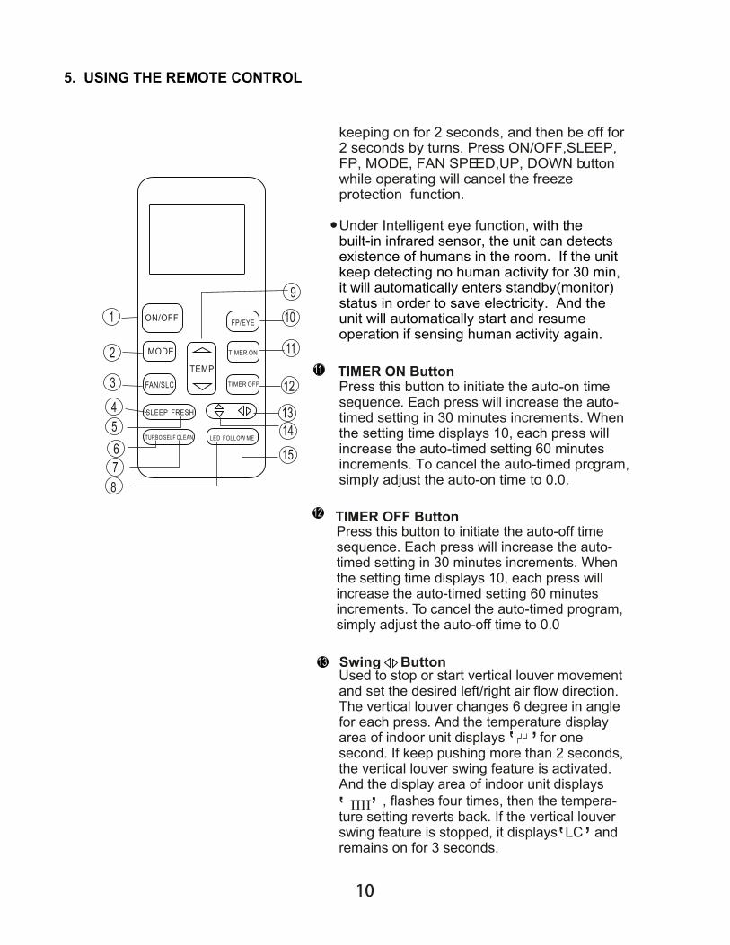
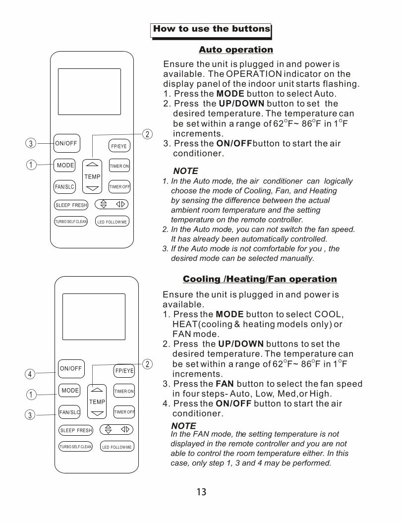
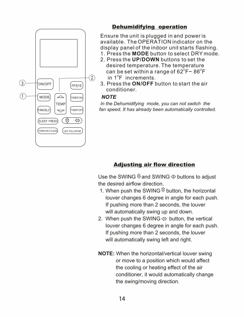
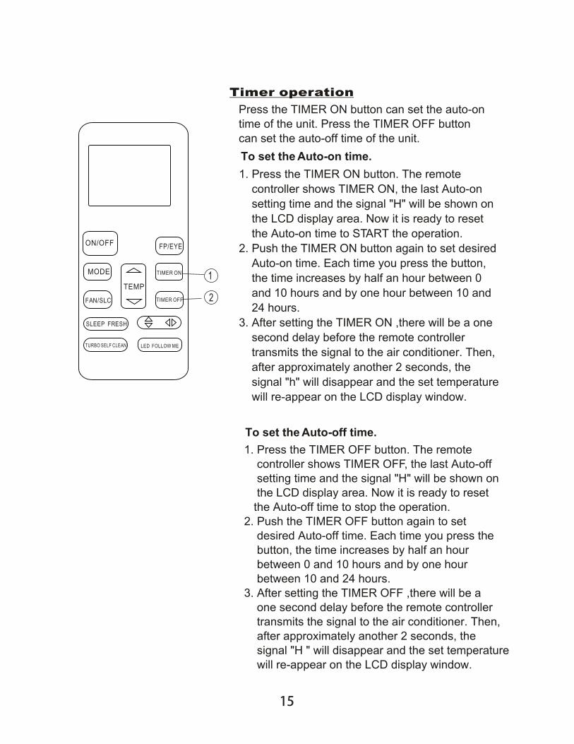
5. USING THE REMOTE CONTROL
10
11
12
13
14
15
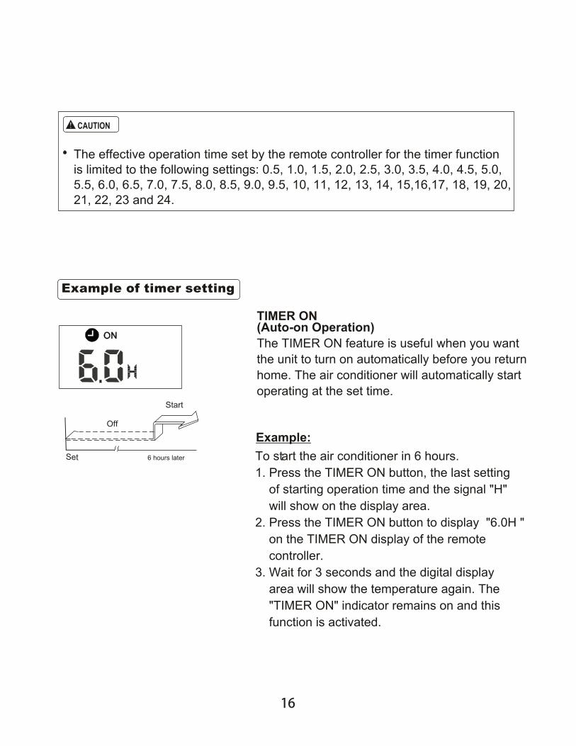
16
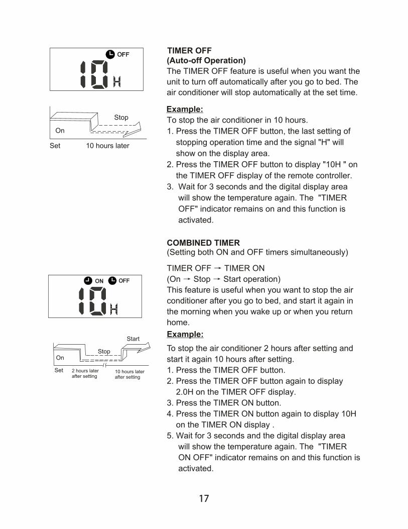
17
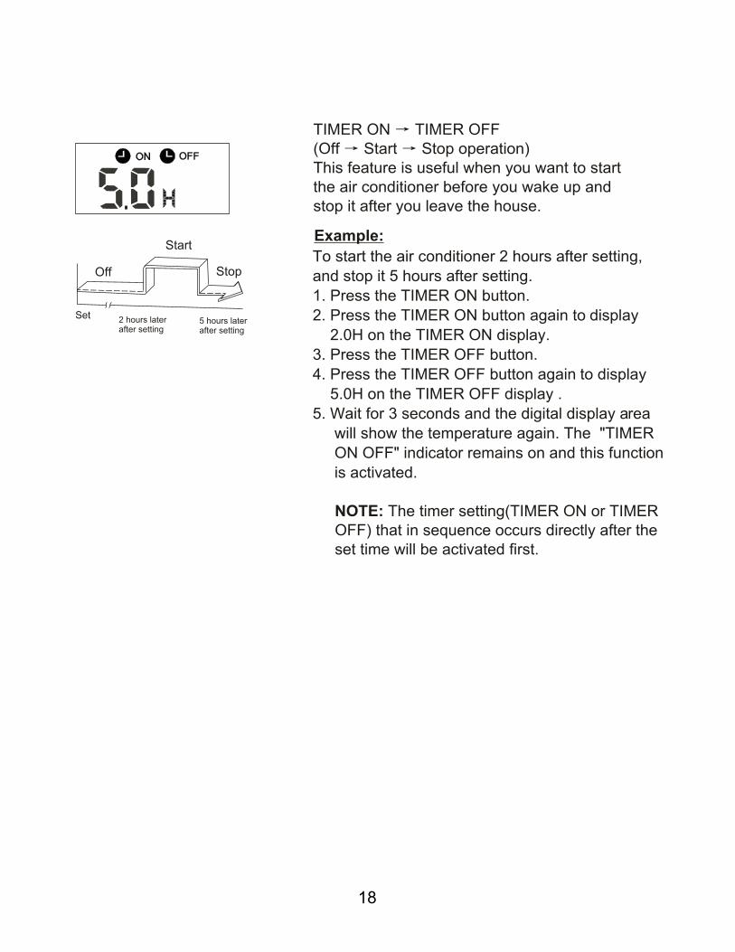
18

Use the system in the following temperature for safe andeffective operation.The Max operation temperature for the air conditioner.(Cooling/Heating)
1 If air conditioner is used outside the above conditions, the unit may function abnormally.
Room relative humidity should be less than 80%. If the relative humidity exceeds 80%, the surface of the air conditioner may condense water. Please set the vertical air flow louver to its maximum angle (vertical to the floor), and set the speed to "HIGH".
Optimum performance is achieved within this operating temperature range.
2
3
Fig. 5-1
Fig. 5-2 Fig. 5-3
The following should be reviewed to ensure an economical operation. (Refer to corresponding chapter put a space between chapter and for for details)
Auto-swingPress the SWING button, the louver will swing up and down automatically.
When coolingAdjust the louver downwards. (horizontally)(Refer to Fig.5-2).When heatingAdjust the louver vertically(Refer to Fig.5-3).
Three-minute protection featureA protection feature prevents the air conditioner from activating for approximately 3 minutes when it restarts immediately after operation.
Power failureA power failure during an operation will stop the unit completely.
The OPERATION lamp on the indoor unit will flashing when power is restored.To restart an operation, push the ON/OFF button on the remote controller.Lightning or a mobile telephone operating nearby may cause the unit to malfunction.
Disconnect the unit from its power source and then connect the unit to the power source again. Push the ON/OFF button on the remote controller to restart the operation.
Adjust the air flow direction properly to avoid wind flowing toward your body.
Adjust the room temperature properly to avoid over cooling and over heating. When cooling, close the curtains to avoid direct sunlight.
To keep cool or warm air in the room, refrain from opening doors or windows unnecessarily.
Set the timer for the desired operating time.
Never put obstructions near the air outlet or the air inlet. Doing so will cause lower efficiency, even a sudden stop.
If you don't plan to use the unit for a long time, please discon-nect power and remove the batteries from the remote control-ler. When the power switch is connected, some energy will be consumed, even if the air conditioner isn't in operation. Also, switch the power on 12 hours before you restart the unit to ensure a smooth operation.
A clogged air filter will reduce cooling or heating efficiency, so clean it once every two weeks.
Manual SwingPress the Air Direction button,the louver can be fixed at a desir-ed angle.The louver swings (upward or downward ) to a certain angle for each press.
CAUTION
Table 3-1
32 °F~86°F / 0°C ~ 30°C
62 °F ~ 90°F( 17°C ~ 32°C)
62 °F ~ 90°F( 17°C ~ 32°C)
Cooling operation
Drying operation
Heating operation(cooling only type without)
Mode
Temperature Outdoortemperature
(for the models with low temperature cooling system)
temperatureRoom
32 °F~122°F / 0°C ~ 50°C
32 °F~122°F / 0°C ~ 50°C
5 °F~122°F / -15°C ~ 50°C
5 °F~76°F / -15°C ~ 24°C
With this new technology, the display area display EC (if applicable) and the LED indication lamps continue to flash when the outdoor unit detects refrigerant leakage.
Louver Angle Memory Function(optional): For some models, the machine is special designed with the louver angle memory function.Power failure during operation or pressing the ON/OFF button on the remote controller will stop the unit completely.When the power restores or pressing the ON/OFF button on the remote controller again,the unit restarts automatically with the previous open angle of the horizontal louver retained by the memory function.So we strongly recom-mend that you do not set the open angle of the horizontal louver too low in case the condensed water forms and drops from the horizontal louver. Press the Manual control button and the open angle of the horizontal louver will return to the standard angle.
Refrigerant Leakage Detection(optional):,,
6. AIR CONDITIONER OPERATIONS AND PERFORMANCE
7. HINTS FOR ECONOMICAL OPERATION
8. ADJUSTING AIR FLOW DIRECTION
19

Do not try to adjust the horizontal louver by hand.When adjusting by hand, the mechanism may not operate properly or condensation may drip from the air outlets.
CAUTION
Table 6-1
Adjust the Air Flow Direction Left and RightHold the knob and move the louver.You will find knobs on the left-side and the right-side of the blades.(Refer to Fig.5-4)
Maintenance after a long off period
Maintenance before a long stop period
Check and remove everything that might be blocking the inlet and outlet vents of the indoor units and outdoor units.
Clean the air filters and casings of indoor units. Refer to "Cleaning the air filter" for details on how to proceed and make sure to install clean air filters in the proper position.
Turn on the power at least 12 hours before operating the unit to ensure smoother operation. As soon as the power is turned on, the remote controller display appear.
Let the indoor units run in fan only operation for about half a day in order to dry the unit's interior.
Clean the air filters and casings of the indoor units. Refer to " Cleaning the air filter" for details on how to proceed and make sure to install clean air filters in the proper position.
Cleaning the air filter
In case of filter blockage, the working efficiency of the air conditioner may greatly decrease. The air filter can prevent the dust or other particulate from going inside.Therefore, the filter must be cleaned once every two weeks during long time use.
If the air conditioner is installed in a dust y place, clean the the air filter frequently.
If the accumulated dust is too heavy to be cleaned, please replace the filter with a new one(a replaceable air filter is an optional fitting).
Fig. 5-4
Before opening the front panel, be sure to stop the operation and turn the breaker OFF.Do not touch the metal parts on the inside of the indoor unit, as it may result in injury.
Open the front panel.How to open the front panel:(Refer to Fig.7-1).
Select the air flow best suits you.(Please refer to Fig. 7-2.)
When setting the air flow selection switch to .The air conditioner automatically decides the appropriate blowing pattern depending on the operating mode/situation.
During Dry mode,so that the cold air does not come into direct contact with people,air is blown through the upper air outlet.
Regardless of the operating mode or situation,air blows from the upper air outlet.Use this switch when you do not want air coming out of the lower air outlet. (For example when occupants are sleep.)
Operatingmode
Situation
Blowingpattern
COOL mode HEAT mode
When the room has becomes totally cool, or when one hour has passed since turning on the air condition-er.So the air does not come into dir-ect contact with people,air is blo-wn through the upper air ou-tlet,room tempe-rature is equaliz-ed.
At start of operation or other times when the room is not fully cooled.
At times other than below.( Normal time.)
Air is blown from the upper and lower air outlets for high spe-ed cooling during COOL mode,and for filling the room with warm air during HEAT mode.
At start or when air temperature is low.
So the air does not come into direct contact with people.Air is blown upper air outlet.
Before you clean the air conditioner, be sure the power supply is off.
Check if the wiring is damaged or disconnected.
Use a dry cloth to wipe the indoor unit and remote controller.
A wet cloth may be used to clean the indoor unit only if it is very dirty.
Never use a damp cloth on the remote controller.
Do not use a chemically-treated duster for wiping. Never leave cleaning material on the unit for a long.time because it may damage or fade the surface of the unit.
Do not use benzine, thinner, polishing powder, or similar solvents for cleaning.
These may cause the plastic surface to crack or deform.
CAUTION
CAUTION
When setting the air outlet selection switch to .
9. AIR FLOW SELECTION
10. MAINTENANCE
20
Air Outlet Selection Switch
especial function filter
Fig.7-1
Fig.7-2
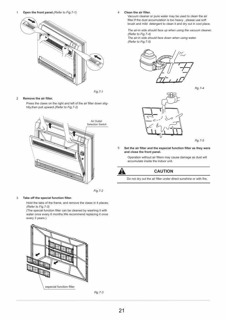
Do not dry out the air filter under direct sunshine or with fire.
Open the front panel.(Refer to Fig.7-1)1
Remove the air filter.2
Clean the air filter. Vacuum cleaner or pure water may be used to clean the air filter.If the dust accumulation is too heavy , please use soft brush and mild detergent to clean it and dry out in cool place.
The air-in side should face up when using the vacuum cleaner.(Refer to Fig.7-4)The air-in side should face down when using water. (Refer to Fig.7-5)
Press the claws on the right and left of the air filter down slig-htly,then pull upward.(Refer to Fig.7-2)
Take off the special function filter.3Hold the tabs of the frame, and remove the claws in 4 places. (Refer to Fig.7-3)(The special function filter can be cleaned by washing it with water once every 6 months.We recommend replacing it once every 3 years.)
Set the air filter and the especial function filter as they were and close the front panel.
5
Operation without air filters may cause damage as dust will accumulate inside the indoor unit.
4
Fig.7-3
Fig.7-4
Fig.7-5
CAUTION
21

Symptom 1: The system does not operate
Symptom 2: Change into the fan mode during cooling mode
Symptom 3: White mist comes out of a unit
Sptom 4: Noise of air conditioners cooling
The air conditioner does not start immediately after the ON/OFF button on the romote controller is pressed. If the operation lamp illuminates, the system operation is normal.To prevent compressor motor overload, the air conditioner starts 3 minutes after it is turned ON.
If the operation lamp and the "PRE-DEF indicator(cooling and heating type) or fan only indicator(cooling only type)" illuminate, it means you choose the heating model, When starting, if the compressor has not started, the indoor unit displays an" anti cold wind" protection message because of the overlow outlet temperature.
In order to prevent the indoor evaporator from freezing, the system will change into fan mode automatically, and then restore to the cooling mode after soon.
When the room temperature drops to the set temperature, the compressor turns off and the indoor unit switches to fan mode; when the temperature increases, the compressor starts again. The same event occurs when the unit is in the heat mode.
Symptom 3.1: Indoor unit
Symptom 3.2: Indoor unit, outdoor unit
Symptom 4.1: Indoor unit
When the humidity is high during the cooling operation and the interior of an indoor unit is extremely contaminated, the temperature distribution inside a room becomes uneven. It is then necessary to clean the interior of the indoor unit. Ask your dealer for details on cleaning the unit. This operation requires a qualified service technician.
When the system changes over to the heating operation after a defrost operation, moisture generated by the defrost process becomes steam and is exhausted.
A continuous low "shah" sound is heard when the system is in the cooling operation or at a stop. When the drain pump (optional accessories) is in operation,this noise is heard.
A "pishi-pishi" squeaking sound is heard when the system stops after a heating operation. Expansion and contraction of plastic parts caused by a temperature change produce this noise.
Symptom 4.2: Indoor unit, outdoor unit
A continuous low hissing sound is heard when the system is in operation. This is the sound of refrigerant gas flowing through both the indoor and the outdoor units.
A hissing sound which is heard at the start or immediately after a stopping operation or defrost operation. This is the noise of the refrigerant caused by flow stop or flow change.
Symptom 4.3: Outdoor unit
When the tone of operating noise changes. This noise is caused by the change of frequency.
.
Symptom 5: Dust comes out of the unit
Symptom 6: The unit emits odors.
When the unit is used for the first time in a long time. This is because dust has accumulated within the unit.
The unit can absorb the smell of rooms, furniture, cigarettes, etc., and then emit them.
Symptom 7: The outdoor unit fan does not spin.
During operation. The speed of the fan is controlled in order to optimize product operation.
The operation lamp is flashing rapidly (5Hz). The lamp is still flashing rapidly after you turn off the power and then turn it on again.(Refer to Table 9-1)
The remote controller malfunctions or the button does not does not work.
A safety device such as a fuse, a breaker frequently actuates.
Obstacles or water enter the unit.
Water leaks from an indoor unit.
Another malfunction occurs.
If one of the following malfunctions occur, stop the operation, shut off the power, and contact with your dealer.
If the system does not properly operate the above mentioned cases or one of the above mentioned malfunctions is evident, investigate the system according to the following procedures. (Refer to Table 9-2)
11. FOLLOWING SYMPTOMS ARE NOT AIR CONDITIONER TROUBLES
12.1. Troubles and causes of air conditioner malfunctions
12. TROUBLESHOOTING
22

Table 9-1
NO. Malfunction timer lamp running lamp (flashes per second)
1
2
3
4
5
6
7
8
display (nixie tube)
Refrigerant leakage detection malfunction
OFFEC
Water-level alarm malfunction 8EE
OFF
Outdoor room temperature sensor open circuit or short circuit F1
2
Outdoor condenser pipe temperature sensor error
3
4 5
ONF2
E3Indoor fan speed malfunction OFF
E4Indoor room temperature sensor open circuit or short circuit
OFF
E5Evaporator coil temperature sensor open circuit or short circuit
OFF
E9Other malfunction of twins model OFF9
Communication malfunction between indoor and outdoor units
OFFE1
10
11
12
13Discharging air temperature sensor error F3
Outdoor EEPROM error F4
Communication malfunction between two indoor units (for twins model)
E8 OFF
F0 1
10
9
7
6
5
4
2
1
Current overload protection
Indoor EEPROM error E0 OFF
14
15
16
17
18
19
20
21
22
Outdoor fan speed malfunction (Only for DC fan motor)
T2b sensor error
F5
F6
6
7
1 2
ON
ON
ON
ON
ON
ON
Inverter module IPM protection P0 Flash
High/Low voltage protection P1 Flash
High temperature protection of compressor top P2
3
Outdoor low temp. protection P3 4
Compressor drive error P4 5
Mode conflict P5 6
Flash
Flash Flash Flash
23
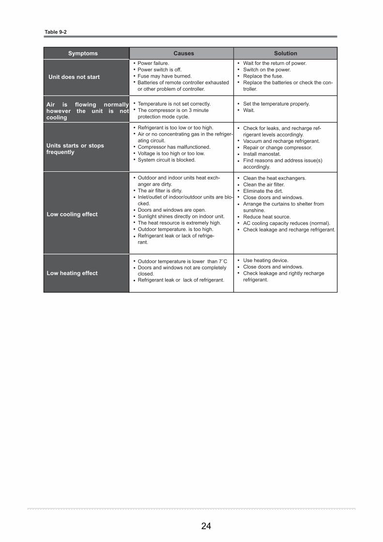
Clean the heat exchangers.Clean the air filter.Eliminate the dirt.Close doors and windows.Arrange the curtains to shelter from sunshine.Reduce heat source.AC cooling capacity reduces (normal).Check leakage and recharge refrigerant.
Air is flowing normally however the unit is not cooling
Units starts or stops frequently
Low cooling effect
Low heating effect
Power failure.Power switch is off.Fuse may have burned.Batteries of remote controller exhausted or other problem of controller.
Temperature is not set correctly.The compressor is on 3 minute protection mode cycle.
Refrigerant is too low or too high.Air or no concentrating gas in the refriger-ating circuit.Compressor has malfunctioned.Voltage is too high or too low.System circuit is blocked.
Outdoor and indoor units heat exch-anger are dirty.The air filter is dirty.Inlet/outlet of indoor/outdoor units are blo-cked.Doors and windows are open.Sunlight shines directly on indoor unit.The heat resource is extremely high.Outdoor temperature. is too high.Refrigerant leak or lack of refrige-rant.
Wait for the return of power.Switch on the power.Replace the fuse.Replace the batteries or check the con-troller.
Set the temperature properly.Wait.
Check for leaks, and recharge ref-rigerant levels accordingly.Vacuum and recharge refrigerant.Repair or change compressor.Install manostat.Find reasons and address issue(s) accordingly.
Use heating device.Close doors and windows.Check leakage and rightly recharge refrigerant.
Outdoor temperature is lower than 7˚C Doors and windows not are completely closed.Refrigerant leak or lack of refrigerant.
SolutionSymptoms Causes
Unit does not start
Table 9-2
24
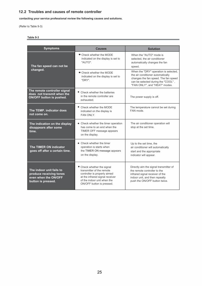
contacting your service professional review the following causes and solutions.
(Refer to Table 9-3)
Symptoms Causes
The fan speed can not be changed.
Check whether the MODEindicated on the display is set to"AUTO".
Check whether the MODEindicated on the display is set to "DRY".
When the "AUTO" mode isselected, the air conditioner automatically changes the fanspeed.
When the "DRY" operation is selected,the air conditioner automatically changes the fan speed. The fan speed can be selected during the "COOL" , "FAN ONLY", and "HEAT" modes.
The remote controller signal does not transmit when the ON/OFF button is pushed.
Check whether the batteriesin the remote controller areexhausted.
The power supply is off.
The indoor unit fails to produce receiving tones even when the ON/OFF button is pressed.
Check whether the signal transmitter of the remotecontroller is properly aimedat the infrared signal receiverof the indoor unit when the ON/OFF button is pressed.
Directly aim the signal transmitter ofthe remote controller to the infrared signal receiver of the indoor unit, and then repeatly push the ON/OFF button twice.
The indication on the displaydisappears after sometime.
Check whether the timer operation has come to an end when the TIMER OFF message appears on the display.
The air conditioner operation willstop at the set time.
The TIMER ON indicator goes off after a certain time.
Check whether the timeroperation is starts whenthe TIMER ON message appearson the display.
Up to the set time, theair conditioner will automaticallystart and the appropriateindicator will appear.
The TEMP. indicator does not come on.
Check whether the MODE indicated on the display isFAN ONLY.
The temperature cannot be set during FAN mode.
Table 9-3
Solution
1 .2 Troubles and causes of remote controller2
25

Copyright 2014 Carrier Corporation S 7310 W. Morris St. S Indianapolis, IN 46231
Manufacturer reserves the right to change, at any time, specifications and designs without notice and without obligations. Replaces: New
Edition Date: /1411