owner’s manual sl4800 sl1600 sl800 models...
TRANSCRIPT

ControllerModelsSL800SL1600SL4800
Owner’s Manual
®
AUTO ADJUST
STANDARDSTANDARDSENSORSENSORMODEMODE
NEXTNEXT
BACKBACK
ADJUST VALUEADJUST VALUE
RUN MANUAL PROGRAMRUN MANUAL PROGRAM
ACTIVEACTIVE
BYPASSBYPASS
ADVANCED FUNCTIONS
AU
O
ADJ
T
MORE/LESS
ZIPCODE or LATITUDE
SOIL TYPE
PLANT TYPE
SPRINKLER TYPE
RUN
MANUAL ZONE
MANUAL TEST
SYSTEM OFF
SET ZONE RUN TIMES
SET TIME/DATE
SET DAILY START TIMES
SET WATERING DAYS
SET OMIT TIMES/DAYS
EASONAL % ADJUST
ADJUST VALUEADJUST VALUEADJUST VALUEADJUST VALUEADJUST VALUEADJUST VALUE®
SL1600 Manual20J 4/18/06 9:29 PM Page 1

Congratulations! Your SmartLine® irrigation controller isdesigned to maintain the health and quality of your landscapewhile conserving water to minimize your operation costs. TheSmartLine® controller can perform Standard timed wateringschedules or, with the addition of the optional SLW Series On-Site Weather Station, the controller’s Auto Adjust mode willanalyze “on site” weather data to automatically set optimumwatering times for each zone, based on Weathermatic’s patent-ed methodology. Auto Adjust will also save water by automati-cally setting run and soak cycles to minimize runoff.
ATTENTION INSTALLER:
PLEASE READ BEFORE INSTALLING AND SAVE THIS MANUALFOR SYSTEM OWNER.
This controller is not intended for use by young children or theinfirm without supervision. Young children should be supervisedto insure they do not play with this appliance.
If the supply cord is damaged it must be replaced by the manu-facturer, the manufacturer’s service agent or a similarly qualifiedperson in order to avoid a hazard.
U.S. Patent No. 6,314,340
TRADEMARKS:
WeathermaticSmartLine®
Smart Solutions for the Professional
Introduction ®
SL1600 Manual20J 4/18/06 9:29 PM Page 2
1.0 Accessories . . . . . . . . . . . . . . . . . . . . . . . . . . . . . .1
2.0 Getting Acquainted With Your Smartline® Controller . . .22.1 Getting Acquainted With Your
SmartLine® Control Panel . . . . . . . . . . . . . . . .22.2 Programming . . . . . . . . . . . . . . . . . . . . . . . .5
3.0 Programming For Standard Watering Mode . . . . . . . .63.1 Set Time and Date . . . . . . . . . . . . . . . . . . . .63.2 Set Zone Run Times . . . . . . . . . . . . . . . . . . . .63.3 Set Daily Start Times . . . . . . . . . . . . . . . . . . .73.4 Set Watering Days . . . . . . . . . . . . . . . . . . . .73.5 Set Omit Times/Days/Dates . . . . . . . . . . . . . .83.6 Seasonal % Adjust . . . . . . . . . . . . . . . . . . . .9
4.0 Programming For Auto Adjust Watering Mode . . . . .10
5.0 Manual Start Functions . . . . . . . . . . . . . . . . . . . . .14
6.0 Advanced Functions . . . . . . . . . . . . . . . . . . . . . . .156.1 FAULT . . . . . . . . . . . . . . . . . . . . . . . . . . . . .156.2 TESTS . . . . . . . . . . . . . . . . . . . . . . . . . . . . .17
6.2.1 OUTPUTS . . . . . . . . . . . . . . . . . . . . . .176.2.2 BATTERY . . . . . . . . . . . . . . . . . . . . . . .176.2.3 24V PWR . . . . . . . . . . . . . . . . . . . . . .176.2.4 LOCATOR . . . . . . . . . . . . . . . . . . . . . .17
6.3 REVIEW . . . . . . . . . . . . . . . . . . . . . . . . . . . .176.3.1 NEXT RUN . . . . . . . . . . . . . . . . . . . . .176.3.2 DEFICIT . . . . . . . . . . . . . . . . . . . . . . . .18
6.3.3 TEMPDATA . . . . . . . . . . . . . . . . . . . . .186.3.4 TOTL RUN . . . . . . . . . . . . . . . . . . . . . .186.3.5 CLR TOTL . . . . . . . . . . . . . . . . . . . . . .196.3.6 CLR DEF . . . . . . . . . . . . . . . . . . . . . . .19
6.4 RAIN DLY . . . . . . . . . . . . . . . . . . . . . . . . . . .196.5 RUN/SOAK . . . . . . . . . . . . . . . . . . . . . . . . .196.6 ZN:ZN DLY . . . . . . . . . . . . . . . . . . . . . . . . . .196.7 MV:ZN DLY . . . . . . . . . . . . . . . . . . . . . . . . . .206.8 MV/ZONE . . . . . . . . . . . . . . . . . . . . . . . . . .206.9 CLR PGM . . . . . . . . . . . . . . . . . . . . . . . . . . .206.10 Wireless . . . . . . . . . . . . . . . . . . . . . . . . . . .206.11 About . . . . . . . . . . . . . . . . . . . . . . . . . . . . .20
7.0 Troubleshooting . . . . . . . . . . . . . . . . . . . . . . . . . .21 7.1 Total Reset Procedure
For Your SmartLine® Controller . . . . . . . . . . .217.2 Replacing SLW Series Weather Station
9V Battery . . . . . . . . . . . . . . . . . . . . . . . . .217.3 Troubleshooting Checklist . . . . . . . . . . . . . . .22
AppendixChart of World Latitudes . . . . . . . . . . . . . . .25
Table of Contents®
SL1600 Manual20J 4/18/06 9:29 PM Page 3

1.0 Accessories
1
®
SLW Series On-Site Weather StationsSmartLine® weather stations with rain and freeze sensing
SLM4 4-Zone Modulefor SL1600, SL1624, and SL4800
No. 955 Rain SenseRain sensor for use when SLWSeries On-Site Weather Stationis NOT installed.
SLM2 2-Zone Modulefor SL800
SLHUBSmartLine®
communication hub
SLW20
SLM12 12-Zone Modulefor SL1624 and SL4800
SLW10
SmartLine® accessories available through your professional Weathermatic installer. For more information and the Weathermaticdistributor directory, go to www.weathermatic.com.
SL1600 Manual20J 4/18/06 9:29 PM Page 4

2.1 Getting Acquainted With Your SmartLine® Control Panel
SmartLine® Controller LCDDisplay
Provides the following informa-tion when the controller is set toRUN, SYSTEM OFF, or when there is no active watering opera-tion underway (display with program in IDLE mode):
Time of Day
Battery Strength: If batteryicon is solid black, the bat-tery strength is good. If theicon is an outline, you shouldreplace the battery. TheSmartLine® controller utilizesa 9V alkaline battery tomaintain correct time duringa power failure. AC power isrequired to operate valves,but the 9V battery will tem-porarily power the processorand display. (The SL800 usesa Real Time Calendar Clockinstead of a backup batteryto maintain correct time during a power outage. A batteryicon will not be seen in the display unless you turn the dial toany Auto Adjust position to the check the battery in theoptional SLW.)
Communications: If you are utilizing the optional SLWSeries On-Site Weather Station, an antenna icon on thedisplay indicates a good link between the SLW weatherstation and the SmartLine® controller. If the antennabands are flashing, this indicates communication hasoccurred within the last 5 minutes. If no communication hasoccurred for 5 days, the antenna icon will disappear and theSmartLine® controller will utilize zone run times programmedin the Standard watering mode.
Getting acquainted with your SmartLine® Controller 2.0
AUTO ADJUST
STANDARDSTANDARDSENSORSENSORMODEMODE
NEXTNEXT
BACKBACK
ADJUST VALUEADJUST VALUE
RUN MANUAL PROGRAMRUN MANUAL PROGRAM
ACTIVEACTIVE
BYPASSBYPASS
ADVANCED FUNCTIONS
AUTO
ADJUST
MORE/LESS
ZIPCODE or LATITUDE
SOIL TYPE
PLANT TYPE
SPRINKLER TYPE
RUN
MANUAL ZONE
MANUAL TEST
SYSTEM OFF
SET ZONE RUN TIMES
SET TIME/DATE
SET DAILY START TIMES
SET WATERING DAYS
SET OMIT TIMES/DAYS
SEASONAL % ADJUST
ADJUST VALUEADJUST VALUE
PGM SUN MON TUE WED
FAULT
12:00 PMNO ACZONE START
ABCD
THU FRI SAT
PGM SUN MON TUE WED
FAULT NO ACZONE START
ABCD
THU FRI SAT
12:00 PM
Note: If you areutilizing theoptional SLWSeries On-Site
Weather Station, you canalso use the same displayicon to check the status ofthe 9V alkaline battery inthe SLW weather station. Ifyou turn the dial to anyAuto Adjust position, thedisplay battery icon willshow strength for the SLWweather station battery.
2
®
SL1600 Manual20J 4/18/06 9:29 PM Page 5

Next Watering Day or Days: The display will show the wateringday or days in the current week for Program A. To view water-ing days for Program B, C or D just press the PGM button.
Fault Indicator: Appears ONLY when a fault is detected. Turndial to Advanced Functions to view faults. Once you turn thedial to Advanced Functions, the fault indicator will stop flashingbut will continue to appear on the screen until the fault isremoved or user clears fault in Advanced Functions. If fault iscleared in Advanced Functions, it will appear again the nexttime the program runs if the fault is not corrected.
No AC: Appears when there is no AC supply to the controller.
PGM Button: The SmartLine® controller has 4 watering pro-grams (A, B, C, and D). This is like having 4 controllers in one.You can assign zones to any program you like or more thanone program except that zones assigned to Program D cannotbe given a run time in A, B, or C. Program D will operate con-currently with A, B, or C. Display will alternately show bothprograms while the concurrent schedule is running. Program Dis normally used for micro irrigation with low flow and long runtimes. Sprinkler zones should be assigned to A, B, or C.
Programs A, B, and C will stack operations. This means that ifyour run time for Program A overlaps B or C, then B will notstart until A is completed and so on. If you want exact starttimes for all programs, make sure your total run time for eachprogram can complete before the next program run is sched-uled to start.
RUN MANUAL PROGRAM Button:
Press to initiate a watering operation when the programming dialis set in either the RUN or SYSTEM OFF position. The SmartLine®
controller will run Program A. Or, you can push the PGM buttonbefore you push the RUN MANUAL PROGRAM button to selectthe program you want to run. You can use the NEXT button toadvance to other zones in a program that you have started. RunManual Program will override any omits, delays or sensor pause.
Special Feature: You can also use the RUN MANUAL PRO-GRAM button to start a continuous run operation. If you pressand hold the RUN MANUAL PROGRAM button for 15 seconds,the selected program will operate in a continuous loop. In otherwords, it will keep running the program continuously until thedial is switched to SYSTEM OFF. This feature is only operablein the Standard mode.
Display With Program Running: When a program is running,the screen will display: program that is operating; zone num-ber that is operating; and run time remaining. An ORANGELED indicates program is in PAUSE mode waiting for a pro-grammed delay in the controller to expire (run/soak, mastervalve delay, zone to zone delay, omit time). The display willsay PAUSE while waiting to begin watering.
Display With Dial In SYSTEM OFF Position: When the SmartLine®
controller dial is in the SYSTEM OFF position, the processorand clock continue to operate and all program values areretained in the non-volatile memory. In the SYSTEM OFF posi-tion, there is no power to valves and no automatic wateringwill occur. If the dial is in the SYSTEM OFF position at 12:00
2.0 Getting acquainted with your Smartline® Controller
3
®
SL1600 Manual20J 4/18/06 9:29 PM Page 6

am, all Auto Adjust wateringdeficits are cleared and nonew deficits will accumulate.The RUN MANUAL PRO-GRAM button can still beused to start a program. TheRED LED will be displayedwhen controller is turned toSYSTEM OFF.
If you move the dial to anyposition other than RUN orSYSTEM OFF, and there is nocontrol panel activity for 30minutes; the controller willreturn to the RUN mode, andthe display screen will showthe idle default screen or willreturn to a program inprogress that was interrupted.
Mode Button: Used to selectAuto Adjust or Standardwatering. During normaloperation the MODE LED willdisplay GREEN. It will change to ORANGE during a pause inoperation and will display RED when SmartLine® controller dialis turned to SYSTEM OFF.
Sensor Button: Used to activate or bypass optional sensors forrain, freeze, or wind. If these sensors are connected to yourSmartLine® controller, they will override watering operations if
the ACTIVE LED is selected. Ifyour sensor/s have pausedyour system operation, theACTIVE LED will be RED untilthe sensor/s allow wateringto resume. In the event of a“rain” pause, the LED willchange from RED toORANGE for 48 hours ofadditional pause time beforethe LED displays GREEN andsystem operation resumes.During a sensor pause, AutoAdjust Watering deficits willdecrement to 0 at the rate of1" per hour. The sensor LEDwill display GREEN againwhen the sensor/s are nolonger pausing your systemoperation.
If you wish to deactivate the sensors, use the SENSOR button tolight the green BYPASS LED. Example: You wish to water afterfertilizing and your rain sensor is still pausing the watering pro-gram. As long as the BYPASS LED is lit, the sensors will notpause your system operation.
Getting acquainted with your Smartline® Controller 2.0
Note: No water-ing will takeplace when the
MODE LED is RED.However, the SmartLine®
controller will retain pro-grams and currentdate/time. An ORANGELED means watering ispaused temporarily due to:run/soak, master valvedelay, zone to zone delay,or omit hours. A programin operation will alsopause if you turn the dialto any position other thanRUN or SYSTEM OFF. Theprogram in operation willresume (1) when you returnthe dial to RUN or (2) ifthere is no programmingactivity for 30 minutes.
Note: The SEN-SOR button canbe used to
bypass rain and freezesensors regardless ofwhether your SmartLine®
controller is in Standard orAuto Adjust mode. Thebypass feature does NOToverride the SLW On-SiteWeather Station’s ability tocontinue to provide datato your SmartLine® con-troller for Auto Adjustoperation. It can only beused to bypass rain andfreeze pause functions.
4
®
SL1600 Manual20J 4/18/06 9:29 PM Page 7
2.2 Programming
Your SmartLine® controller has two operating modes: STAN-DARD mode or Weathermatic’s patented Auto Adjust mode.The Standard mode uses user assigned zone run times. TheAuto Adjust mode overrides user assigned zone run times andcalculates zone run times based on the location of the site,inputs by zone, and weather readings from the SLW weatherstation. Note: Auto Adjust requires the optional SLW weatherstation.
Both the Standard mode and Auto Adjust mode use the userinput daily start times, watering days, omit times/days, andseveral advanced functions (rain delay, zone to zone delay,and master valve settings).
Important Note: Zone run times must be entered for every zonein use for the controller to recognize the zone in eitherStandard or Auto Adjust modes.
Using the Programming Buttons
A FLASHING DISPLAY indicates that user choices are available.The ▲ and ▼ arrow buttons are used to scroll through numericvalues or to make a choice of menu options.
NEXT and BACK Buttons: When watering zones are being pro-grammed, the left side of the display will indicate the zone num-ber. The NEXT and BACK buttons are used to scroll through thezones. If the flashing display indicates a menu selection ratherthan a numeric value, the NEXT button will open the menu forfurther programming. The BACK button will exit the menu andcause the chosen value to be saved in memory.
RAPID ADVANCE: While programming, holding down the ▲ or▼ arrow button will cause the flashing display value to rapidlyadvance. Rapid advance can also be used with the NEXT andBACK buttons to rapidly advance through zones.
MENUS WITHIN MENUS: In cases where there are menus withinmenus, each press of the BACK button will return to the nexthigher menu until the top level menu of the dial position is reached.
A VALUE CHANGE will be entered in memory any time you (1)move to a different menu or (2) move the programming dial toa different position.
2.0 Getting acquainted with your Smartline® Controller
5
®
SL1600 Manual20J 4/18/06 9:29 PM Page 8

® Programming for Standard Watering Mode 3.0
3.0 Programming for Standard Watering Mode
3.1 Set Time And Date
Use ▲ and ▼ arrowbuttons to change theflashing value for thehour. Scrolling past 12will automaticallychange AM/PM.Remember holdingdown the UP or DOWN arrow button will rapidly advancethrough the flashing menu. (Note: For international users, if con-troller is powered by 230VAC, 50 Hz AC, display will read ininternational hours rather than AM/PM.)
Use NEXT button to flash minutes. Use ▲ and ▼ arrow buttonsto set minutes. Push NEXT to access calendar setting. Use ▲and ▼ arrow buttons to set month/day/year. (Note: For inter-national users, the display will read day/month/year.) YourSmartLine® controller has a 100-year calendar, so when youhave entered the correct date, the SmartLine® controller willautomatically display the correct day of the week. YourSmartLine® controller will automatically adjust for leap years. Amanual adjustment is required for Daylight Savings Time.
3.2 Set Zone Run Times
Your SmartLine® con-troller will displayremaining hours, min-utes and seconds whena zone is watering.However, in this posi-tion you are onlyrequired to set minutes (or hours and minutes) for each zone asdesired for operation time. Seconds are not selectable.
Use NEXT and BACK buttons to select zone for run time setting.All zones are selectable from 1 minute to 9 hours and 55 min-utes. Run times of OFF to 59 minutes are selectable in oneminute increments. Run times of 1 hour to 9 hours 55 minutesare selectable in 5-minute increments. Use ▲ or ▼ arrow but-tons to set flashing time values for each zone. If a zone is not tobe used, set it to OFF. A zone with an OFF setting is OFF inboth Standard and Auto Adjust modes.
Push PGM button to assignzone time in one or more pro-grams. Note: Program D is forconcurrent operation for microirrigation zones. Zonesassigned to Program D cannotbe assigned to Program A, B,or C. Display will say USED ifattempt is made to enter timein A, B, or C for a zonealready assigned operating time in D.
6
SET TIME/DATE
SET ZONE RUN TIMES
Note: If displayshows “0ZONES,” this
indicates no SLM4 modulesare currently installed orhave ever been installedunder AC power with thecontrol panel firmly closed.
SL1600 Manual20J 4/18/06 9:29 PM Page 9

Caution: If an unused zone is turned on and activates a pumpstart relay, the pump may overheat or cause a pipe to burst. Toprevent operating a pump with no flow (dead heading), makesure all unused zones are set to OFF.
3.3 Set Daily Start Times
8 daily start times areavailable per program.The SmartLine® con-troller has 4 programs,so you have 32 avail-able start times for each24-hour day. Check pro-gram icon in display to see whether you are working in A, B, C,or D. Use PGM button to move between programs. Use NEXTbutton to select start times 1 through 8 for each program. Use ▲and ▼ arrow buttons to set each start time desired. Note: Besure you select the AM/PM time as desired by scrolling past 12.
(For international users, the display will show internationalhours instead of AM/PM.) Start times are selectable in 10-minute increments.
Important: You need to know the total run time you haveentered for each program to allow time for each cycle to com-plete before the next program begins. If a run time overlapsinto the next start time, the SmartLine® controller will stack thestart times within each program and between programs, begin-ning those operations at the time the previous operation is com-
pleted, beginning with starttime 1 in Program A. If a con-current program in D is run-ning at the same time as aprogram in A, B or C, the dis-play will alternately show theicon for both programs in thedisplay.
All zones to be utilized mustbe assigned a run timewhether you are using theStandard or Auto AdjustMode. Your SmartLine® con-troller will use Zone RunTimes as the backup program for Auto Adjust.
3.4 Set Watering Days
In this dial position youcan select a DAYS,INTERVAL, orODD/EVEN schedule.Use ▲ and ▼ arrowbuttons to select whichtype of schedule youwant in your SmartLine® controller. Remember to check theProgram (PGM) selection showing in the display. You can selecta different watering schedule for each program if you wish.
1
®
7
3.0 Programming for Standard Watering Mode
SET DAILY START TIMES
Note: Run/Soakperiod canreduce the need
to set multiple start timesfor the purpose of prevent-ing runoff. Using the com-bination of multiple starttimes and Run/Soak cyclescan lead to extendedwatering windows sinceRun/Soak cycles areapplied to each start time.
SET WATERING DAYS
SL1600 Manual20J 4/18/06 9:29 PM Page 10

If you select DAYS, then use the NEXT button to step througheach day of the week and the ▲ and ▼ arrow buttons to selectON or OFF status for each day. Days selected to water will bedisplayed at the top of the display.
If you select an INTERVAL schedule, push NEXT button. Theflashing number indicates the day interval for watering.SmartLine® controller will allow an interval of 1 (every day) to30 (water once every 30 days). After you have selected theinterval you want, push NEXT to set the day you want the inter-val schedule to start on. Use ▲ and ▼ arrow buttons to selectstart day at top of display.
If you select ODD/EVEN day scheduling, push NEXT buttonand then use ▲ or ▼ arrow buttons to select watering on ODDor EVEN days. If ODD is flashing on the display when you turnthe dial to another position, you have selected ODD. The sameis true for EVEN. When you return the dial to RUN, you canview the next day that your schedule will run. The SmartLine®
Controller will run ODD or EVEN programming at the nextavailable start time, even if it is on the same day that you setup the schedule. If you are using an ODD schedule, the
SmartLine® controller will not water on the 31st day of a month
and February 29th of a leap year to prevent two consecutive
watering days (31st and 1st or 29th and 1st).
3.5 Set Omit Times/Days/Dates (Optional)
The omit settings areused to set a wateringblackout period. Forexample, if you live in amunicipality that restrictsoutdoor wateringbetween 10:00 am and6:00 pm, you can blackout that time period. If a watering pro-gram in progress is paused for a blackout period, theORANGE LED will display during the pause. The wateringcycle will automatically resume at the end of the blackout peri-od. Use the ▲ or ▼ arrow buttons to select OMIT:TIME,OMIT:DAYS, and OMIT:DATES. You may choose any or all ofthese omit options.
If you want a watering blackout for the same period each day,select OMIT:TIME. Then push NEXT. A forward (>) arrow indi-cates the beginning time for the blackout. Use ▲ and ▼ arrowbuttons to set beginning time. Then push NEXT. A reverse arrow(<) indicates the end time for the blackout. Use ▲ and ▼ arrowbuttons to set ending time. The OMIT:TIME function will pauseany active watering program until the blackout period hasexpired. Scrolling the beginning time (forward arrow) between12:00 am and 11:50 pm causes NONE SET to appear andclears the omit time.
If you want to omit a specific day or days each week fromwatering schedules, select OMIT:DAYS with the ▲ and ▼ arrowbuttons. Then push NEXT. Display will show a day of the week
®
8
Programming for Standard Watering Mode 3.0
SET OMIT TIMES/DAYS
SL1600 Manual20J 4/18/06 9:29 PM Page 11
with Omit or Allow flashing. Use ▲ and ▼ arrow buttons toselect Omit or Allow. Use NEXT or BACK to scroll betweendays of the week. Omitted days will be visible at the top of thedisplay. Any running user program will be stopped at midnightin order to honor omit days or dates. Programs scheduled tostart on an omit day will be skipped.
If you want to omit specific dates during the year, select OMIT:DATES. Then push NEXT. Enter the month and date. Push NEXTto enter up to 7 dates. Scrolling the month value between 12and 1 causes mm/dd to appear and clears the omitted date.Any running user program will be stopped at midnight in orderto honor omit days or dates.
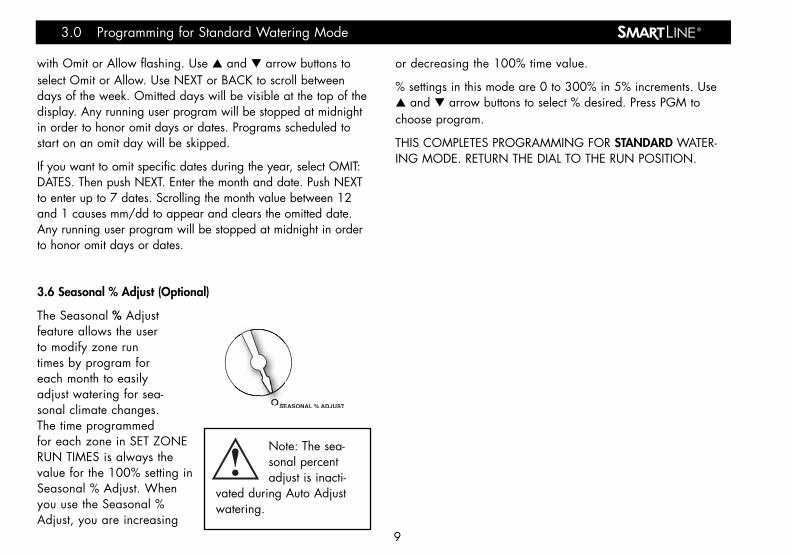
3.6 Seasonal % Adjust (Optional)
The Seasonal % Adjustfeature allows the userto modify zone runtimes by program foreach month to easilyadjust watering for sea-sonal climate changes.The time programmedfor each zone in SET ZONERUN TIMES is always thevalue for the 100% setting inSeasonal % Adjust. Whenyou use the Seasonal %Adjust, you are increasing
or decreasing the 100% time value.
% settings in this mode are 0 to 300% in 5% increments. Use▲ and ▼ arrow buttons to select % desired. Press PGM tochoose program.
THIS COMPLETES PROGRAMMING FOR STANDARD WATER-ING MODE. RETURN THE DIAL TO THE RUN POSITION.
®
9
3.0 Programming for Standard Watering Mode
SEASONAL % ADJUST
Note: The sea-sonal percentadjust is inacti-
vated during Auto Adjustwatering.
SL1600 Manual20J 4/18/06 9:29 PM Page 12

4.0 Programming for Auto Adjust Watering Mode
Weathermatic’s patented Auto Adjust overrides user assignedzone run times and calculates zone run times based on thelocation of the site, inputs by zone, and weather readings fromthe SLW Series On-Site Weather Station. Auto Adjust isdesigned to help you protect your landscaping, reduce wastefulrun off, and minimize your water costs.
Warning: Auto Adjust positions on the dial can onlybe selected when the optional SLW Series On-SiteWeather Station accessory is installed. Additionally,Standard Program Function must be set up complete-
ly (see Sections 4.1–4.4) before setting up Auto Adjust mode.Auto Adjust Mode zone times for zones in use simply replacesthe zone run times inputs with a calculated value.
Step 1: Set ZIP Code or Latitude
Auto Adjust operationfirst requires that theSmartLine® Controllerknow “where in theworld” it is located.Users in the USA canset location by ZIP Code. Users outside of the USA can setlocation by latitude. Use ▲ and ▼ arrow buttons to select ZIPCode (USA) or LATITUDE. To find your latitude, see chart ofWorld Latitudes on page 25.
If you are setting a ZIP Code, push NEXT. Display will show 5numerical positions for ZIP Code settings. Use ▲ and ▼arrow buttons to set the flashing number. Then push NEXT toflash the next number. Use ▲ and ▼ arrow buttons to set sec-ond number. Continue process until all 5 numbers of your ZIPCode are set.
If you are outside the USA, you will enter LATITUDE. You canuse the ▲ and ▼ arrow buttons to choose any latitude between60 degrees south and 60 degrees north. 0 degrees setting ismarked as EQUATOR.
Step 2: Enter Auto Adjust Data for Zones:
Enter Auto Adjust data for zones: Sprinkler Type, Plant Type,Soil Type, and MORE/LESS. The SmartLine® controller cannotcalculate run times without Auto Adjust data for each zone andwithout Zone Run Times assigned to each operational zone,which serve to back up Auto Adjust mode.
Sprinkler Type: In orderto calculate run time,the controller mustknow the expected pre-cipitation rate for eachzone. Use NEXT andBACK buttons to movebetween zones. Use ▲ and ▼ arrow buttons to set zone toOFF or to specify the precipitation rate.
® Programming for Auto Adjust Watering Mode 4.0
ZIPCODE or LATITUDE
10
SPRINKLER TYPE
SL1600 Manual20J 4/18/06 9:29 PM Page 13

Precipitation rate can be entered two ways: by sprinkler type orby specific precipitation rate. If you do not know the specificprecipitation rate for the zone, you can select the sprinklertype, or watering equipment used on that zone: Spray, Rotor,Drip, or Bubbler irrigation. The SmartLine® controller will applya default precipitationrate for the sprinkler typeselected. If you know thespecific precipitation rateexpected for the zone,as stated by the sprinklermanufacturer, you canuse the ▲ or ▼ arrowbuttons to scroll past the sprinkler types and select that number.For USA users, inches per hour will be displayed (.2 to 3.0inches per hour). For international users, the controller will dis-play precipitation numbers in centimeters per hour. As a rule inAuto Adjust mode, the lower the precipitation rate entered, thelonger the zone run time will be to achieve required plant lifeneeds.
Plant Type: This posi-tion is used to specifythe type of plant materi-al to be watered byeach zone as an impor-tant component ofdetermining the water-ing needs for each zone. Use the ▲ and ▼ arrow buttons toselect plant type or percent for each zone. Press NEXT and
BACK buttons to access each zone. Plant type selections are:CTurf (cool turf like bluegrass); WTurf (warm turf like St.Augustine); Shrubs; Annuals (floral beds); Trees; and Nativeplants. The SmartLine® controller formula uses cool turf mowedat 4 to 6 inches tall as the base watering number (100%) orcrop factor. The cool turf default is 80% considering averagemowing heights of 2 to 3 inches, which result in less transpira-tion and lower water requirements. If you prefer more specificinput, you can scroll past the plant types and use % designa-tions of 10 to 300%. Forexample, a Native plantzone might be assigned30% rather the defaultof 25%. As a rule inAuto Adjust mode, thehigher the plant typepercentage entered, thelonger the zone run timewill be to achieverequired plant life needs.
For maximum water savings, it is recommended that your sprin-kler system be zoned with a separate valve for each type ofplant material. If you have mixed types of plants in a singlezone, you will need to select which type of plant to use in thedetermination of waterrequirements.
Soil Type: Soil settingsfor soil type anddegree of slope are
®
11
PLANT DEFAULT %TYPE
CTURF 80%WTURF 60%SHRUBS 60%ANNUALS 150%TREES 80%NATIVE 25%
PLANT TYPE
SOIL TYPE
4.0 Programming for Auto Adjust Watering Mode
SPRINKLER DEFAULTTYPE PRECIPITATION RATE
SPRAY 1.5 inch per hourROTOR 0.5 inch per hourDRIP 1.1 inches per hourBUBBLER 2.3 inches per hour
SL1600 Manual20J 4/18/06 9:29 PM Page 14
®
used to enable your SmartLine® controller to automatically cal-culate the maximum length of a zone run time before pausingwatering for a calculated period to allow the water to soak intothe soil. These Run/Soak (also called Cycle/Soak) periods basedon industry standard formulas reduce wasteful runoff caused bywatering more than the soil can absorb. The Run/Soak featureincluded in Advanced Functions can be manually entered for usewith the Standard mode. However, in the Auto Adjust mode, theSmartLine® controller will automatically calculate Run/Soak timeswith soil inputs made at the soil type position on the dial.Run/Soak settings made in Advanced Functions are not activewhen controller is in Auto Adjust mode.
Use the ▲ and ▼ arrow buttons to select Clay, Loam or Sandsoil type for each zone.
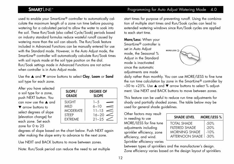
After you have selecteda soil type for a zone,push NEXT button. Youcan now use the ▲ and▼ arrow buttons toselect degrees of slope(elevation change) foreach zone. Set eachzone for 0 to 25degrees of slope based on the chart below. Push NEXT againafter making the slope entry to advance to the next zone.
Use NEXT and BACK buttons to move between zones.
Note: Run/Soak period can reduce the need to set multiple
start times for purpose of preventing runoff. Using the combina-tion of multiple start times and Run/Soak cycles can lead toextended watering windows since Run/Soak cycles are appliedto each start time.
More/Less: When yourSmartLine® controller isset in Auto Adjustmode, the Seasonal %Adjust in the Standardmode is inactivatedsince the automaticadjustments are madedaily rather than monthly. You can use MORE/LESS to fine tunethe run time calculation by zone in the SmartLine® controller by–50 to +25%. Use ▲ and ▼ arrow buttons to select % adjust-ment. Use NEXT and BACK buttons to move between zones.
This feature can be useful to reduce run time adjustments forshady and partially shaded zones. The table below may beused for general shade guidelines.
Other factors may resultin needing to useMORE/LESS for fine tuneadjustments includingsprinkler efficiency, zoneefficiency, and wind.Sprinkler efficiency variesbetween types of sprinklers and the manufacturer’s design.Zone efficiency varies based on the design layout of sprinklers
12
Programming for Auto Adjust Watering Mode 4.0
SLOPE/ DEGREE OFGRADE SLOPE
SLIGHT 1–5MILD 6–10MODERATE 11–15STEEP 16–20EXTREME 21–25 SHADE LEVEL MORE/LESS %
TOTAL SHADE -50% FILTERED SHADE -20% MORNING SHADE -10% AFTERNOON SHADE -30%
MORE/LESS
SL1600 Manual20J 4/18/06 9:29 PM Page 15

in a zone, sometimes overlapping or sometimes not. Highwinds can serve to dry out plant and soil to increase the needfor water. For optimum results considering the many uniquevariables in each zone, users should periodically station plantlife health and water usage, especially after initial controllersetup, so proper adjustments can be made.
THIS COMPLETES PROGRAMMING FOR AUTO ADJUST.RETURN THE DIAL TO THE RUN POSITION.
Step 3: Activating the SLW Series On-Site Weather Station:
Verify the time and date areset and the ZIP Codes orLatitude are set on theSmartLine® Controller beforeproceeding with SLW weath-er station activation.
On the SLW weather station,press and hold down theRain Sense test tab in thecenter of the rain sensor for 15 seconds.
On the SmartLine® controller, verify that the antennaicon appears on the bottom line of the LED display. Theantenna indicates communication has been established.The SLW weather station provides rain and freezepause functions to prevent watering during periods of rain andfreezing weather. The rain override will pause watering after a
minimum of 1/8th inch of rainfall is received (the factory set-
ting of 1/8th inch can be changed incrementally up to 1 inchby sliding the rain sensor into the desired position). The SLWweather station will also pause watering when the outside tem-perature drops to 37 degrees Fahrenheit (1.5 degrees Celsius).The Sensor LED will display RED during these rain or freezeperiods. 24VAC power to the valves is reconnected when thetemperature is again above 37 degrees F (1.5 degreesCelsius). However, after a rain event, the SmartLine® controllerwill continue to pause watering for 48 hours after the rain sen-sor has disengaged, in order to prevent over-watering.
Step 4: MODE Button:
Press the MODE button on the control panel to place theSmartLine® controller in the Auto Adjust mode. A GREEN LEDon the Auto Adjust position will confirm that you have communi-cated with the SLW weather station. If there is no SLW weatherstation installed or ZIP Code or Latitude or time/date setting,pressing the MODE button will flash the Auto Adjust LED to REDand then return to the Standard mode. When this occurs, youcan press and hold the MODE button to see a scrolling mes-sage indicating the reason Auto Adjust mode is not available.
®
13
4.0 Programming for Auto Adjust Watering Mode
SL1600 Manual20J 4/18/06 9:29 PM Page 16

5.0 Manual Start Functions
The SmartLine® controller has two dial positions for manual sys-tem starts:
Manual Zone
Manual Zone allowsuser to water a singlezone for specified peri-od of time. Use NEXTand BACK buttons toselect zone. Use ▲ and▼ arrows to select runtime for the zone. A zone can be operated with the ManualZone function regardless of whether the zone has an assignedrun time. You must return dial to RUN for Manual Zone opera-tion to begin. All manual watering operations will overridewatering day settings, omit settings, and rain/freeze events.
Manual Test
The Manual Test canbe used to set a testrun time for all zoneswhich have anassigned zone runtime in any program.Any zone without anassigned zone run time will NOT run in the Manual Test. Use
▲ and ▼ arrow buttons to set Manual Test run time. TheManual Test can be set to run a minimum of 10 seconds or amaximum of 10 minutes. You must return dial to RUN forManual Test operation to begin.
The Manual Test will also detect open circuits (less than 30 mAdraw) on any used zone or a short on any output (master valveor zone). If the display indicates FAULT when the dial is in theManual Test position, refer to Advanced Functions proceduresto identify the fault.
In addition to manual operation using Manual Zone andManual Test, you can run a program by pressing and holdingthe ▲ arrow button, also labeled RUN MANUAL PROGRAM.Be sure to use the PGM button to select the specific programyou choose to run manually. RUN MANUAL PROGRAM canbe stopped by pressing the UP arrow button or moving thedial out of the RUN position. If you push the RUN MANUALPROGRAM button and press and hold down for 15 seconds,the selected program will operate in a continuous loop. Inother words, it will keep running the program continuouslyuntil the dial is switched to SYSTEM OFF. This feature is onlyoperable in the Standard mode.
All manual watering operations will override watering day set-tings, omit settings, and rain/freeze events.
®
14
Manual Start Functions 5.0
MANUAL ZONE
MANUAL TEST
SL1600 Manual20J 4/18/06 9:29 PM Page 17

6.0 Advanced Functions
Advanced Functions provides information and allows moretechnical inputs commonly used by professional installers.Advanced Functions contains menus within menus. Each pressof the BACK button will return you to a higher level until the toplevel of the Advanced Functions dial position is reached.
Refer to the chart to the right for the location of features withinthe menus.
6.1 FAULT
This feature is used to identify problems that may require atten-tion or repair in order to insure proper operation of the system.Use NEXT button to view the type of fault. If more than onefault exists, you can use the ▲ and ▼ arrow buttons to searchfor additional faults. Use NEXT button one more time and it willflash KEEP. If you want to clear the fault, hit the UP arrow and itwill flash CLEAR. If you turn the dial out of the AdvancedFunctions positions while CLEAR is flashing, the fault icon onthe display will disappear. However, if the cause of the fault isnot corrected, the controller will continue to skip watering azone with a fault and will resume the flashing FAULT icon onthe display each time that zone is operated.
®
15
6.0 Advanced Functions
TESTS
FAULTS(If present)
REVIEW
RAIN DLY
BATTERY
OUTPUTS
24V PWR
LOCATOR
CLR PGM
MV:ZN DLY
ZN:ZN DLY
RUN/SOAK
AdvancedFunctions
NEXT RUN
CLR TOTL
TOTL RUN
TEMP/DATA
DEFICIT
WIRELESSFor future use.
ABOUT
CLR DEF
ADJUST VALUEADJUST VALUE
NEXTNEXT
BACKBACK
SL1600 Manual20J 4/18/06 9:29 PM Page 18

® Advanced Functions 6.0
SCROLLING FAULT MESSAGE
ZONE XX SHORT
ZONE XX OPEN
NO RECENTCONTACT
WITH WEATHER STATION
REMOTE BATTERY FAILURE
ZONE XXINSUFFICIENTWATERING
OPPORTUNITY
FAULT DESCRIPTION
OUTPUT SHORT CIRCUIT: A load placed on any output that results in a current draw exceeding the skip current setting will result in a fault within 3 AC cycles after the output is turned on. The output will be skipped until the next watering program attempts to use it. If the MV/P output is shorted, all zones using it will effectively be skipped. The fault indication can be manually cleared or will be automatically cleared if the short condition goes away; and the output turns on successfully. See Section 6.2.1 Outputs for instructions on reading actual current.
OUTPUT OPEN CIRCUIT: If a used zone exhibits a load that results in a current draw less than 30 mA during a scan test, a fault is declared, but operation continues normally. The fault indication can be manually cleared or will be automatically cleared if a load exceeding 30 mA is placed on the output, and the output turns on successfully. See Section 6.2.1 Outputs for instructions on reading actual current.
COMMUNICATIONS FAILURE: If the SmartLine® controller is in Auto Adjust mode, and the daily high/low temperature has not been received by midnight, the communication fault is set. Also, if the battery in the SLW weather station is dead, the communication fault is set. If 5 days pass without communication, the controller will revert to the Standard mode Zone Run Times. The fault indication can be manually cleared or will clear automatically once communication is received.
If the SmartLine® controller receives communication from the SLW weather station that indicates the remote battery is low, the fault is set. The fault indication can be manually cleared, or will clear automatically if the SLW weather station sends another message that indicates a good battery. The fault will also clear if no communication is received for a full day (i.e. communication failure). See Section 7.2 Replacing SLW Series Weather Station 9V Battery.
INSUFFICIENT WATERING OPPORTUNITY: If the SmartLine® controller is in Auto Adjust mode, and a daily deficit is calculated that results in a zone watering deficit in excess of the 1.5” maximum, the deficit is capped to the maximum and the fault is set. The calculation can also occur as part of the deficit gap recovery process, which happens when the SmartLine® controller loses power for over a day and then recovers. The fault is cleared manually.
16
SL1600 Manual20J 4/18/06 9:29 PM Page 19

6.2 TESTS
Your SmartLine® controller can assist you with several diagnos-tic functions by pressing NEXT when TESTS appears.
6.2.1 OUTPUTS
Use ▲ arrow to select OUTPUTS function. Then use NEXTand BACK buttons to scroll through MV and Zone Valves toview AC Amp reading for each valve. Scroll back to OUT-PUTS display to move to next diagnostic function. Typicalrange is 150 to 350 mA per valve with a valve connected.Current exceeding 350 mA per valve could be an indicationof a partial short. Current readings less than 30 mA will indi-cate an open circuit. Note: If you have more than one valveon a zone, the SmartLine® controller will measure total cur-rent for the combined valves.
6.2.2 BATTERY
Use ▲ arrow button and Battery will flash. Use NEXT buttonand you will see the DC V reading for the backup battery inthe SmartLine® controller. A minimum of 7.5 volts is requiredto power the processor and display. If the reading is less than7.5 volts, the battery should be replaced. This function doesnot provide voltage readings for the 9V battery in the optionalSLW weather station. However, if you turn the dial to any AutoAdjust programming position, the battery icon reading you seein the display is for the battery in the SLW weather station.
(The SL800 uses a Real Time Calendar Clock instead of abackup battery to maintain correct time during a power out-age. A battery icon will not be seen in the display unless youturn the dial to any Auto Adjust position to the check the bat-tery in the optional SLW.)
6.2.3 24V PWR
This function displays output voltage at the transformer.Normal reading is 24 to 30 volts AC.
6.2.4 LOCATOR
This feature will create a“chatter” for a selectedvalve as a convenientmethod of locating buriedvalves. Use NEXT andBACK buttons to scroll to thevalve you want to “chatter.”
6.3 REVIEW
6.3.1 NEXT RUN
NEXT RUN is the total amount of run time Auto Adjust hascalculated for each zone for the next watering day based onthe deficit numbers and is available for review when you are
®
17
6.0 Advanced Functions
Note: If you arenot utilizing amaster valve,
you must turn off the sys-tem water pressure at themanual cut-off valve orwater meter for this featureto work. Pressure must beoff while attempting to“chatter” a valve. TheSmartLine® controller willautomatically turn off MVoutput when a “chatter”test is initiated.
SL1600 Manual20J 4/18/06 9:29 PM Page 20

using Auto Adjust. NEXT RUN times will return to zero aftereach watering day’s cycles are complete. Use the NEXT andBACK buttons to review the NEXT RUN time for each zone.
6.3.2 DEFICIT
Deficit is the amount of water (displayed in inches) that needsto be replaced for your plant material due to water lossthrough evapotranspiration – evaporation from soil and tran-spiration from plants. Your SmartLine® controller will calcu-late the water deficit each day at midnight based on datacommunicated to it by the SLW series weather station at11:50 pm of the prior day. The water deficit will continue toaccumulate until the next scheduled watering cycle and willreturn to a zero reading when watering is finished. TheSmartLine® controller uses an internationally recognized for-mula called the Hargreaves formula for calculating evapo-transpiration.
When Advanced Functionsis displaying DEFICIT, useNEXT and BACK buttons toview deficit for each zone.The NEXT or BACK buttonswill also return you to theDEFICIT level. When dis-play is at the DEFICIT level,you can then use the UParrow button to move toNEXT RUN readings.
If you wish to reduce the deficit numbers, press and holddown either the ▲ or ▼ arrow button for 5 seconds. Thisallows you to use the ▼ arrow button to reduce the latestdeficit for the zone to as low as 0 inches.
Deficit is only available for review when you are using AutoAdjust mode.
6.3.3 TEMPDATA
TEMPDATA provides the daily high/low temperature readingsin Fahrenheit (Celsius for export) from the SLW weather sta-tion for the past 5 days. Press NEXT to view readings for theprior day. Press NEXT again to view the readings from oneday before the prior day followed by the daily high anddaily low. Continue pressing NEXT to view up to 5 days oftemperature history.
6.3.4 TOTL RUN
TOTL RUN is the total run time for each zone since the dateshown (default date in the SmartLine® controller is January 1,2000 shown as 01/01/00). You can review TOTL RUN foreither the Standard or Auto Adjust modes. After you selectTOTL RUN with the UP arrow button, use NEXT to view thedate when TOTL RUN accumulation began. Use NEXT againto view the total run times for each zone.
You can use the NEXT and BACK buttons to move through thezones. After you go through all the zone positions, use the NEXTbutton one more time to take you back to the TOTL RUN screen.
®
18
Advanced Functions 6.0
Note: If the dialis in the SYSTEMOFF position at
12:00 am, all Auto Adjustwatering deficits arecleared and no newdeficits will accumulateuntil dial is moved fromSYSTEM OFF position.
SL1600 Manual20J 4/18/06 9:29 PM Page 21
6.3.5 CLR TOTL
CLR TOTL is used to clear and reset the total run time foreach zone shown in the TOTL RUN menu.
From the CLR TOTL menu, press NEXT and the display willshow KEEP. If you want to clear the TOTL RUN time and resetthe accumulation date, press either the ▲ or ▼ arrow buttonto display CLEAR. With CLEAR showing in the display, eitherpress NEXT or BACK or turn the dial to complete the clearingand resetting. This feature will stop accumulations on a zoneafter 255 hours of cumulative zone run time.
6.3.6 CLR DEF
To clear deficits, press NEXT. Use ▲ or ▼ arrow buttons to selectKEEP or CLEAR. Press NEXT or BACK to exit CLEAR DEFICITS.
6.4 RAIN DLY
The rain delay feature allows user to globally suspend wateringoperations for all programs for a selected number of days ineither the Standard or Auto Adjust watering modes.
Use ▲ and ▼ arrow buttons to select 1 to 7 days for wateringsuspension. The watering blackout will automatically be clearedfrom the SmartLine® controller after the assigned days haveexpired and watering will resume at the next available starttime. Auto Adjust watering deficits will reset at zero and willnot resume accumulation until the delay has ended.
6.5 RUN/SOAK
The purpose of Run/Soak is to break up long run times thatoften cause wasteful runoff. The Run/Soak is programmable foreach program if you are using the Standard watering mode.Note: If you are using Auto Adjust, these inputs are not usedsince the Run/Soak period is automatically calculated.
Use NEXT button to access RUN time allowed before the zonewatering pauses for the specified soak time. Use PGM button toselect program. Use ▲ and ▼ arrow buttons to set RUN timefrom OFF to 30 minutes (SmartLine® controller default is OFF).Use NEXT button to access soak time required for water to infil-trate into soil before zone watering is continued. Use the ▲and ▼ arrow buttons to set soak time from 1 minute to 2 hoursin one-minute increments.
6.6 ZN:ZN DLY
This function allows user toset delay times between zonestarts for use in systems withslow closing valves or pumpsystems that are operatingnear maximum flow or haveslow well recovery. Use ▲and ▼ arrow buttons tochange value. Adjustable inone-minute increments from 0(the SmartLine® controller
®6.0 Advanced Functions
19
Note: TheMasterValve/Pump Start
circuit will operate duringthe first 5 seconds of anyprogrammed delay to aidin closing of the valve andto avoid unnecessarycycling of the pump. The 5second period is program-mable in the MV:ZN DLYsetting. (See Section 6.7)
SL1600 Manual20J 4/18/06 9:29 PM Page 22

default setting) to 30 minutes; adjustable in 10 minute incre-ments in settings from 30 minutes to 3 hours.
6.7 MV:ZN DLY
(Master Valve Advance Open and Delayed Close): This func-tion allows the user to set a delay time between the opening ofthe master valve and the opening of the first zone valve as wellas a delay between the closing of the last zone valve and theclosing of the master valve.
Use the NEXT button to enter menu. Select setting for the ONDelay or OFF Delay by pressing NEXT. Use ▲ and ▼ arrowbuttons to select delay time. Use arrow buttons to set ON Delaytime from 0 seconds to 1 minute in 1 second increments. OFFDelay can be set from 0 seconds to 3 minutes in 1 secondincrements.
6.8 MV/ZONE
This feature is used to indicate which zones will use the mastervalve/pump start relay. Use NEXT button to set each zone ONor SYSTEM OFF (SmartLine® controller default is master valveON for all zones). Use ▲ and ▼ arrow buttons to select ON orOFF. Use NEXT button to select zone.
Caution: If an unused zone is turned on and activates a pumpstart relay, the pump may overheat or cause a pipe to burst. Toprevent operating a pump with no flow (dead heading), makesure all unused zones are set to OFF.
6.9 CLR PGM
This feature allows the user to clear all programmed values spe-cific to a selected program. All zone run times and daily starttimes will be set to OFF; watering days will default to Days ofthe Week (all on); Season % will equal 100% for all monthsand Run/Soak will be OFF. Omit times/days and Auto Adjustsettings are not reset when clearing a program.
From the CLR PGM menu, press NEXT and the display willshow KEEP. Use PGM button to select program to be cleared.Then, press either the ▲ or ▼ arrow button to display CLEAR.With CLEAR showing in the display, either press NEXT or BACKor turn the dial to complete the clearing of the selected pro-gram. Likewise, with KEEP showing in the display, either pressNEXT or BACK or turn the dial to keep the selected program.
6.10 WIRELESS
Reserved for future use with wireless remote options.
6.11 ABOUT
Provides information on software version in the SmartLine®
controller.
®
20
Advanced Functions 6.0
SL1600 Manual20J 4/18/06 9:29 PM Page 23

®
7.0 Troubleshooting
7.1 Total Reset Procedure For The SmartLine® controller
A total reset will clear all programming data in the SmartLine®
controller including the time/date setting. All settings will returnto factory default.
For the SL1600, SL1624, and SL4800:
• Turn dial to Advanced Functions.
• While pressing the ▲ arrowbutton, use an open paperclip or ballpoint pen to pushin the Reset switch located onthe back of the operatingpanel. Release the reset but-ton while continuing to pressand hold the ▲ arrow button.
• Once the display shows CLEARING, release the ▲ arrow button.
• Reprogram SmartLine® controller.
For the SL800:
• Unplug the power supply on the side of the SL800.
• Turn dial to Advanced Functions.
• While continually holding down on the UP arrow button,reapply the power connection to the SL800.
• The display will read “CLEARING” to verify that the Reset iscomplete. Re-enter your controller settings.
7.2 Replacing SLW weatherstation 9V Battery
• For models SLW20 andSLW25, remove the twoPhillips screws that hold theSLW weather station accesspanel in place (taking carenot to lose them) and removethe access panel.
• For models SLW10,SLW15, open snap-in dooron the bottom of the SLWweather station to accessbattery.
• Replace the existing bat-tery with a new 9V alka-line battery.
• You will now need to re-ini-tialize the station. Press theleft button on the station panel and wait 3 seconds. Youshould see a series of 4 GREEN blinks from the LED if com-munication is re-established with the controller.
• Return to the controller and push the MODE button to placethe controller back in the Auto Adjust position. If communica-tion with the station is successful, the Auto AdjustGREEN LED will light and the antenna icon willappear in the display.
7.0 Troubleshooting
Note: If you onlywant to clear thevalues in one pro-
gram only, you should use theClear Programs (CLR PGM)function located in AdvancedProgramming (See Sec. 6.9). Press
leftbutton
LED
21
SL1600 Manual20J 4/18/06 9:29 PM Page 24

®® Troubleshooting 7.0
PROBLEMController won’t allow entry to Auto Adjust and/or no antenna icon on display
No Display
FAULT icon on display
SOLUTIONSInstall optional SLW weather station
Initialize SLW weather station according to instructions in Auto Adjust section
Push and hold down MODE button for a scrolling message indicating needed information. Enter needed information for time, date, and ZIP Code or Latitude
Replace battery as shown in Section 7.2
Check cable and connections at controller
Replace SLW weather station. If SmartLine® controller has no communication for 5 days, it will revert to Standard program settings
Replace SLHUB communication hub
Note: You can use the diagnostic panel on the SLW to determine the reason the controller will not let you enter Auto Adjust. Push the diagnostic button once. Observe the blinking LED.
First Blink RED—The 9V battery in the SLW should be replaced. Second or Third Blink RED—The SLW is defective and should be replaced. Fourth Blink Red—Communication problem is in the cable or SLHUB.
If all SLW diagnostic blinks are GREEN, all SLW functions and communications between the SLW and SLHUB are working properly. Recheck data entry required into controller.
Check power wiring, breaker, and be sure control panel is firmly closed. Replace 9V battery
Replace transformer. Likely power surge damage
Check solenoid(s) and wiring (turn dial to Advanced Functions for fault information in Sec 6.1)
Check solenoid(s) and wiring
Check programming watering days, verify omit settings are not excessive, and review accuracy of Auto Adjust settings for sprinkler and plant type
CAUSESSystem requires installation of SLW weather station
SLW weather station not initialized to controller
Missing required Auto Adjust settings
9V battery in SLW weather station is drained
Communication cable problem
Defective SLW weather station
Defective SLHUB communication hub
No power to controller
No 24V power from transformer
Shorted or open condition on a zone(s)
Shorted MV/P
Insufficient watering opportunity
(Continued on next page.)
22
SL1600 Manual20J 4/18/06 9:29 PM Page 25
®7.0 Troubleshooting
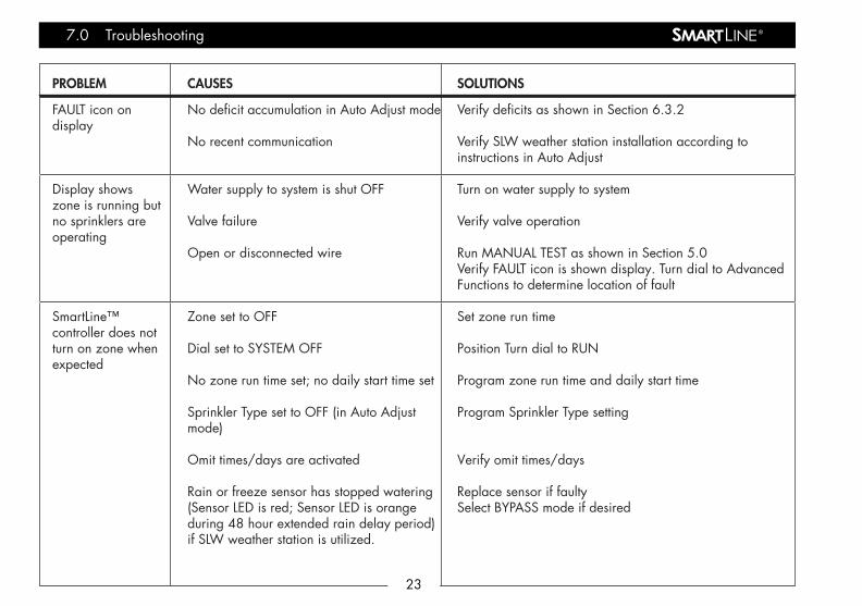
PROBLEM
FAULT icon on display
Display shows zone is running but no sprinklers are operating
SmartLine™ controller does not turn on zone when expected
CAUSES
No deficit accumulation in Auto Adjust mode
No recent communication
Water supply to system is shut OFF
Valve failure
Open or disconnected wire
Zone set to OFF
Dial set to SYSTEM OFF
No zone run time set; no daily start time set
Sprinkler Type set to OFF (in Auto Adjust mode)
Omit times/days are activated
Rain or freeze sensor has stopped watering (Sensor LED is red; Sensor LED is orange during 48 hour extended rain delay period) if SLW weather station is utilized.
SOLUTIONS
Verify deficits as shown in Section 6.3.2
Verify SLW weather station installation according to instructions in Auto Adjust
Turn on water supply to system
Verify valve operation
Run MANUAL TEST as shown in Section 5.0Verify FAULT icon is shown display. Turn dial to Advanced Functions to determine location of fault
Set zone run time
Position Turn dial to RUN
Program zone run time and daily start time
Program Sprinkler Type setting
Verify omit times/days
Replace sensor if faultySelect BYPASS mode if desired
23
SL1600 Manual20J 4/18/06 9:29 PM Page 26

®® Troubleshooting 7.0
PROBLEM
SmartLine® controller does not turn on zone when expected
Display shows 0 ZONES
CAUSES
Sensor jumper is removed and no sensor is connected (Sensor LED is red)
Sensor wires have been cut (Sensor LED is red)
Zone comes on at unexpected time
Stacked program has commenced normal operation
Time of day or date not set properly Watering days or omit days/dates not set properly
Run/Soak feature has extended watering window
Controller does not operate zone for expected run time
Auto Adjust mode has calculated a different run time than expected
Module not installed
No initial AC power-up of controller
Defective module
SOLUTIONS
Install jumper wire between SEN terminalsSelect BYPASS mode if desired
Repair wires
Program daily start times not set properly or multiple start times set. Check all programs and daily start times
Modify settings (such as daily start times, zone run times) to prevent stacking if undesirable
Review/set time of day and date
Review/set watering days or omit days/dates
Normal operation to allow water infiltration and prevent runoff
Pause for Run/Soak in progress. This is normal operation to allow water infiltration and prevent runoff
Normal operation of Auto Adjust mode to match watering to plant requirements
Install module
Connect AC power and close control panel
Replace module in zone 1-4 position24
SL1600 Manual20J 4/18/06 9:29 PM Page 27

World Latitudes
®Appendix
25
80° N
70° N
60° N
50° N
40°N
30° N
20° N
10° N
0°
10° S
20° S
30° S
40° S
50° S
60° S
70° S
80° S
SL1600 Manual20J 4/18/06 9:29 PM Page 28

®®
Basi
c Pr
ogra
mm
ing
(App
lies
to b
oth
Stan
dard
and
Aut
o A
djus
t Wat
erin
g Sc
hedu
les.
)
Not
es:
1 __
__ 5
___
_ 1
____
5
____
1
____
5
____
1
____
5
____
2 __
__ 6
___
_ 2
____
6
____
2
____
6
____
2
____
6
____
3 __
__ 7
___
_ 3
____
7
____
3
____
7
____
3
____
7
____
4 __
__ 8
___
_ 4
____
8
____
4
____
8
____
4
____
8
____
Pr
ogra
m A
Pr
ogra
m B
Pr
ogra
m C
Pr
ogra
m D
Day
s of
the
wee
k S
M T
W T
F S
S
M T
W T
F S
S M
T W
T F
S S
M T
W T
F S
Odd
/Eve
n ❏
Odd
❏ E
ven
❏ O
dd ❏
Eve
n ❏
Odd
❏ E
ven
❏ O
dd ❏
Eve
n
Inte
rval
(Eve
ry 1
–30
days
) __
____
__ d
ays
____
____
day
s __
____
__ d
ays
____
____
day
s
Om
it D
ays/
Dat
es/T
imes
D
ays:
D
ates
: Ti
mes
: Fro
m>
T
o<
Dai
ly S
tart
Tim
es
SL1600 Manual20J 4/18/06 9:29 PM Page 29

Standard Watering Schedule
Seasonal % Adjust
Program
A
Program B
Program C
Program D
Zone Location
Zone Run Time
Zone Run Time
Zone Run Time
Zone Run Time
1
2
3
4
5
6
7
8
9
10
11
12
13
14
15
16
17
18
19
20
21
22
23
24
PGM
Jan Feb
Mar
Apr M
ay Jun
Jul Aug
Sep O
ct N
ov Dec
A ____%
____% ____%
____% ____%
____% ____%
____% ____%
____% ____%
____%
B ____%
____% ____%
____% ____%
____% ____%
____% ____%
____% ____%
____%
C ____%
____% ____%
____% ____%
____% ____%
____% ____%
____% ____%
____%
D ____%
____% ____%
____% ____%
____% ____%
____% ____%
____% ____%
____%
SL1600 Manual20J 4/18/06 9:29 PM Page 30

Aut
o A
djus
t Wat
erin
g Sc
hedu
leZI
P C
ode/
Latit
ude
____
____
____
____
____
_
S
oil T
ype
Zon
e Lo
catio
n Sp
rinkl
er Ty
pe P
lant
Type
So
il Sl
ope
Mor
e/Le
ss
1
2
3
4
5
6
7
8
9
10
11
12
13
14
15
16
17
18
19
20
21
22
23
24
SL1600 Manual20J 4/18/06 9:29 PM Page 31

Part AD231Rev. B
®
SL1600 Manual20J 4/18/06 9:29 PM Page 32