owner’s manual wwnerw ’s manual 4k ultra hd...
TRANSCRIPT

4K Ultra HD LCD Display
MODELS:RS-840UD
OWNER’S MANUALKWKWKWWNER’S MANUALKW

1
Important Precautions
Electrical Power Related Precautions
Warningn Use only the power cord supplied with the unit or another manufacturer’s authorized cord.
- Failure to do so may result in fire or electrical shock or damage to the display.
n Use only a properly grounded plug and receptacle.- If you do not, you may be electrocuted or injured. Or the display might be damaged.
n Do not use a damaged or loose plug.- This may cause electrical shock or fire.
n Operate the display only from a power source (i.e. voltage) indicated in the product specification.- Otherwise, the display can be damaged, fire can occur or you may be electrocuted. If you are not
sure what type of power supply you have, consult a certified electrician.
n In the presence of thunder and lightning, never touch the power cord and signal cable because it can be very dangerous.- It can cause electric shock.
n Do not connect several extension cords, electrical appliances or electrical heaters to a single outlet. Use a power bar with a grounding terminal designed for exclusive use with the display.- A fire can break out due to overheating.
n Do not touch the power plug with wet hands. Additionally, if the cord pin is wet or covered with dust, dry the power plug completely or wipe dust off before plugging in the cord.
- You may be electrocuted due to excess moisture.
n If you do not intend to use the display for a long time, unplug the power cord from the display.- Covering dust can cause a fire, or insulation deterioration can cause electric leakage, electric shock
or fire.
n Insert the power plug firmly so it cannot come loose.- A loose connection can cause fire. Hold the plug when pulling out the power cord.
n Do not pull the plug out by the wire. Do not bend the power cord with excessive force or put heavy objects on the power cord.- The power line can be damaged, which may cause electric shock or fire.
n Do not insert metal or other conductive materials into the display openings. Additionally, do not touch the power cord right after plugging the cable into the wall input terminal.- You may be electrocuted.
n The power supply cord is used as the main disconnection device. The socket-outlet shall be installed near the equipment and shall be easily accessible.
n Do not unplug the power cord while the display is in use.- Electrical shock can damage the product.
n As long as this unit is connected to the AC wall outlet, it is not disconnected from the AC power source even if the unit is turned off.
Please read these safety precautions carefully before using the display.
Warning Failure to follow those warnings may result in death, serious injury or damage to the display or other property.

2
Important Precautions Important Precautions
Precautions in Installing the Display
Warningn Keep away from heat sources like heaters or open flames.
- Electrical shock, fire, malfunction or deformation may occur.
n Keep the packing anti-moisture material or vinyl packing out of the reach of children.- Anti-moisture material is harmful if swallowed. If swallowed by mistake, force the patient to vomit and
visit the nearest hospital. Additionally, vinyl packing can cause suffocation. Keep it out of the reach of children.
n Do not put heavy objects on the display or sit upon it.- If the display collapses or is dropped, you may be injured. Children must pay particular attention.
n Do not leave the power or signal cable where someone can trip over it.- The passerby can falter, which can cause electrical shock, fire, display breakdown, or injury.
n Install the display in a neat and dry place. Do not use near water.- Dust or moisture can cause electrical shock, fire, or display damage.
n Do not add accessories that have not been designed for this display.
n If you smell smoke or other odors or hear a strange sound from the display, unplug the power cord and contact Customer Service.- If you continue to use without taking proper measures, electrical shock or fire can occur.
n If you dropped the display or the case is broken, turn off the display and unplug the power cord.- If you continue to use without taking proper measures, electrical shock or fire can occur. Contact
Customer Service.
n Do not drop an object on or apply impact to the display. Do not throw any toys or objects at the display.- It can cause injury to humans, problems to the display, and damage the display.
n Keep out of reach of children and do not place toys near the display.
n Make sure the display ventilation hole is not blocked. Install the display more than 10cm away from the wall.- If you install the display too close to the wall, it may be deformed or fire can break out due to internal
heat build-up.
n Do not cover the display with cloth or other material (eg. plastic) while plugged in.- The display can be deformed or fire can break out due to internal overheating.
n Place the display on a flat and stable surface that is large enough to support the display.- If the display is dropped, you may be injured or the display may be broken.
n Install the display where no Electromagnetic Interference occurs.
n Keep the display away from direct sunlight.- The display can be damaged.
n Do not place the display on the floor.- Small children and others may trip over it.

3
Important Precautions
Precautions in Moving the Display
Warningn Make sure to turn off the display.
- You may be electrocuted or the display can be damaged.
n Make sure to remove all cables before moving the display.- You may be electrocuted or the display can be damaged.
n Do not shock the display when moving it.- You may be electrocuted or the display can be damaged.
n Make sure the display faces forward and hold it with both hands to move.- If you drop the display, the damaged display can cause electric shock or fire.
n Do not place the display face down.- This may damage the display.
Precautions in Using/Cleaning the Display
Warningn Do not attempt to disassemble, repair, or modify the display yourself.
- Fire or electric shock can occur.
- Contact Customer Service for repair.
n When cleaning the display, unplug the power cord and scrub gently with a soft cloth to prevent scratching. Do not clean with a wet cloth or spray water or other liquids directly onto the display. An electric shock may occur. (Do not use chemicals such as benzene, paint thinners, or alcohol)
n Keep the display away from water.- Fire or electric shock accident can occur.
n Avoid high temperatures and humidity.
n Do not put or store flammable substances near the display.- There is a danger of explosion or fire.
n Keep the display clean at all times.
n Do not press on the display with a hand or sharp object such as nail, pencil or pen, or make a scratch on it.
n Keep proper distance from the display and rest from time-to-time.- Your vision may be impaired if you look at the display too closely or for too long.
n Keep small accessories out of the reach of children.
n Leaving a fixed image on the display for a long time may cause damage to the display and cause image retention. Make sure to use a screen saver on the display. Burn-in and related problems are not covered by the warranty on this display.
n Spray water onto a soft cloth 2 to 4 times, and use it to clean the front frame; wipe in one direction only. Too much moisture may cause staining.

4
Important Precautions
On Disposal (Only, Hg lamp used Display)
n The fluorescent lamp used in this display contains a small amount of mercury.
n Do not dispose of this display with general household waste.
n Disposal of this display must be carried out in accordance to the regulations of your local authority.
Precautions for Image StickingTo optimize display lifetime and function, pay attention on the following operation usages:
n Normal operating condition
- Operating Temperature: 0°C to 35°C
- Operating Ambient Humidity: 20% to 90%
- Display Pattern: dynamic pattern (real display)
Note: Long-term static display can cause image sticking.
n Operating usages under abnormal condition
a. Ambient condition
- Well-ventilated place is recommended to set up the system.
b. Power and screen saver
- Periodical power-off or screen saver is needed after long-term display.
n Operating usages to protect against image sticking due to long-term static display
a. Suitable operating time
- Under 18 hours a day.
b. Static information display recommended to use with moving image
- Cycling display between 5 minutes information (static) display and 10 seconds moving image.
c. Background and character (image) color change
- Use different colors for background and character, respectively.
- Change colors themselves periodically.
d. Avoid combination of background and character with large different luminance
Note: 1) Abnormal condition just means conditions except normal condition.2) Black image or moving image is strongly recommended as a screen saver.

5
Accessories
Included Accessories
Thank you for your purchase. Ensure that the following accessories are included with your display. If an accessory is missing, please contact the dealer where you purchased the display.
v The accessories included may differ from the images shown below.
Remote Control & Batteries (AAA × 2)
Power Cord*Power Cord for EU
(Optional)
Quick Start Guide
Stand Stand Screws (6 pieces) CD-ROM (User’s Manual)

6
Front View
Name and Function of the Parts* The image shown in the user’s guide could be different from the actual image.
No. Item Description
1 Power indicator Indicate power on or sleep mode status.- Power on: LED lights up.- Power off: LED off.
2 IR Receiver Receive incoming remote control commands.
1 2
Name and Function of the Parts

7
Name and Function of the Parts
Rear View
No. Item Description
1 AC Power Input Connector
Connect the power cord.
2 AC Switch Switch the power supply on/off.
3 RS-232C Serial Ports
Connect several displays with serial port.
4 Ethernet Port Connect to a local area network (LAN) using an Ethernet cable.
5 RGB Port Connect to a PC VGA port.
6 PC Audio Input Port Connect to a PC’s line / audio port.
7 Component/Video Input Ports
Connect to an external device, such as a VCR, STB, or a DVD player.
8 Stereo Audio Line Out
Connect an external audio system or headphones.
INPUT
MENU
VOL
VOL
RS-232 IN RS-232 OUT ETHERNET PC / MUSIC COMPONENT / VIDEO AUDIO OUT
RGB (PC)PC
AUDIO INAUDIOOUT
DPTICALY/V RAUDIOCOMPONENT [GOOD]
LPr/CrPb/Cb
HDMI
USB
UHD60
1
2
1
2
3
4
3
2
1
3 4 5 7 8 9
10
Name and Function of the Parts
6
11
12
1 2

8
Using the Remote ControlName and Function of the Parts
Rear View (continue)
No. Item Description
9 Optical Audio Out
Connect an audio amplifier.
10 HDMI Ports Connect an HDMI equipment or an HDMI-DVI adapter cable to devices such as a DVD player or set-top box.v HDMI Supports High Definition input and HDCP
(High-bandwidth Digital Content Protection). Some devices require HDCP in order to display HD signals.
11 USB Ports Connect to a USB device such as a USB flash drive or USB hard disk drive.
12 HDMI-UHD60 Ports
Connect an HDMI equipment such as a computer, camcorder, or multimedia player which are able to output 4x HDMI with individually 1080p@60Hz resolution and compose to a UHD@60Hz resolution.

9
Using the Remote Control
Name of the Remote Control Buttons
LeftDecrease the• values.Change the • options.
RightIncrease t• he values.Enter the submenu.• Change th• e options.
UpM• ove upward on the selection.Ch• ange selected item.
DownMove d• ownward on the
selection.Change• selected item.
PowerTurn the display on/off.
Installing Batteries into the Remote Control
1. Open the battery cover.2. Install the batteries matching the
correct polarity.Install two 1.5V AA batteries. •
3. Close the battery cover.Dispose the • used batteries in the recycle bin to prevent environmental pollution.
OKEnter th• e submenu.
Confirm the selection.•
Name and Function of the Parts
InputSwitch the input source.
MenuDisplay OSD (on-screen display) menu.
MultimediaEnter the multimedia
mode.
WideChange the display mode.
ExitExit OSD menu.
MuteMute the audio.
VolumeAdjust the volume.
Numbers (0~9, -)Input the number.
BackReturn to the previous
menu/screen.
InfoDisplay the input information.
Audio onlyOnly output audio from the display speaker.

10
Stand Installation
Installing the Stand
1. Place the display with the screen side down on a flat and cushioned surface. Then, attach the stand as shown in the illustration.
2. Secure the stand with the six included screws. Please fasten with a screwdriver.
Note If you do not fasten the screws, the display may fall, which may result in • damage to the product.

11
Removing the Stand
1. Place the display with the screen side down on a flat and cushioned surface. Then, remove the screws.
2. Detach the stand from the display.
Stand Installation

12
VESA FDMI Wall Mounting
This display supports a VESA FDMI compliant mounting interface. These mounts are purchased separately. Refer to the instructions included with the wall mount for more information.v The handles are designed for carrying.
VESA-compatible wall bracket (WxH) Screw type Mount holes number400 x 600 mm M8 4
Mounting on a Wall
INPUT
MENU
VOL
VOL
HandleHandle

13
Connecting to External Devices
HDMI Connection (480p, 576p, 720p, 1080i, 1080p, UHD@24Hz/30Hz)
HDMI supports ultra high definition (UHD) input, high definition input, and HDCP (High-bandwidth Digital Content Protection). Some devices require HDCP in order to display HD signals.
AUDIOIN
HDMI
1
2
3
HDMI to DVI signal cable
VCR/DVD/Set-top BoxNote: Dolby Digital is not supported.
Recommended Connection, Resolution & Picture ModeHDMI Connection, 3840 x 2160@30Hz, dynamic
AUDIOIN
HDMI
1
2
3
HDMI signal cable
VCR/DVD/Set-top BoxDisplay
Display

14
RGB (PC)
PCAUDIO IN
Display
PC
MAC
Macintosh AdapterUse only the standard Macintosh adapter. Do not use other adapter type that is compatible with different signaling system.
B. Connecting with a D-sub(VGA) Signal Input Cable
Connecting to External Devices
PC Connection
Check that the computer, display, and the peripherals are turned off. Then, connect the signal input cable.
A. Connecting with an HDMI Signal Input Cable
HDMI
Display
Audio cable
HDMI-UHD60 Connection (3840 x 2160 @60Hz)Four HDMI ports form a UHD 60Hz. Each connection transmits 1080P @60Hz.
HDMI signal cable
UHD60
4
3
2
1
4
3
2
1
Display
HDMI signal cable
HDMI signal cable
HDMI signal cable
Computer/Camcorder/Multimedia player

15
Audio Out Connection
AUDIO OUT
Display
Audio cable
Connecting to External Devices Connecting to External Devices
Speaker
DPTICAL
Display
Optical audio cable
Audio amplifier
Component Connection
Y/V RAUDIOCOMPOSITE [GOOD]
LPr/CrPb/Cb
Display
Component AV cable
VCR/DVD/Set-top Box
Composite (Video) Connection
Y/V RAUDIOCOMPOSITE [GOOD]
LPr/CrPb/Cb
Display
Composite AV cable
VCR/DVD/Set-top Box

16
Connecting to External Devices
Power Connection
INPUT
MENU
VOL
VOL
Rear side of the display
Power outlet
USB Connection
Ethernet Connection
USB
1
2
Display
USB Flash Drive
ETHERNET
NetworkDisplay
Ethernet (RJ-45) cable
Power cord

17
Connecting to External Devices
Screen Adjustment Options (using the Control Panel)
OSD Menus
No. Item Description
1 Up Select menu item (move up).
2 Down Select menu item (move down).
3 Volume Up - Increase the volume level.- Adjust the settings (increase the value).
4 Volume Down - Decrease the volume level.- Adjust the settings (decrease the value).
5 Power Turn the display on/off.
6 Input Switch the input source.
7 Menu Display/hide the OSD (on-screen display) menu or return to the previous menu.
INPUT
MENU
VOL
VOL
INPUT
MENU
VOL
VOL
1
2
3
4
5
6
7

18
OSD Menus
Menu Options
Menu DescriptionInput Select the input source.
Picture Adjust and refine the picture displayed on your display based on ambient room light and personal preferences.
Audio Adjust the audio settings.
Setup Adjust the general settings such as CEI setting, OSD language, and etc.
Ethernet Configure the network settings.
Wide Select how the picture displays on the screen.
Sleep Timer Set the timer to turn the display off at the preset time.
Note OSD (On Screen Display)The OSD function enables you to adjust the screen status conveniently since it provides graphical presentation.

19
OSD Menus OSD Menus
Adjusting On-Screen Display (OSD) Settings
1 Press the MENU button to display the OSD menu.
2 Use the p/q button to select the main menu.
3 Press the OK or u button to enter the selected menu screen.
4 Use the p/q button to select the menu item.
5 Press the OK or u button to enter the submenu.
6 Use the t/u button to adjust the setting/select the option.
7 Use the OK button to confirm the setting.
8 Press the MENU button to return to the previous menu/exit the OSD menu.
(*operation using the remote control)
Display OSD menu
Select a main menu
Enter the selected
menu
Select a menu
item
Enter the submenu
Adjust the setting
Confirm the
setting
Return to
previous menu

20
OSD Menus
Input Menu
Select the proper input source.
Note You can also access the Input menu by pressing the • INPUT button on the remote control.The available menu options varies depending on the input source.• If the menu items are appears in gray, this indicates that those functions • are not available.

21
OSD Menus
Picture Menu
Menu Option DescriptionPicture Mode
Select a preset view option optimized for different viewing conditions.
Custom• : User can use the user-defined settings as they wish.Cinema• : This mode is normally used in movie. Soft image can be seen in this mode. The picture is somewhat darker than other mode.
OSD Menus

22
OSD Menus
Menu Option DescriptionPicture Mode
Nature• : This mode shows normal and natural image.Sports• : This mode uses high contrast display for clear-cut images ideal for viewing sports events.
Dynamic• : This mode is normally used in department store, Backlight and Sharpness is set to its maximum value. Saturation of Color becomes high. You can see very bright, clear, and sharp image.Game• : This mode increases the brightness and response time level for enjoying video games.
Note “Picture Mode” option is not available if the input source is PC.
Gamma Select the appropriate setting of dark scenery. With greater gamma value, dark scenery looks brighter.
Backlight Adjust the backlight that affects the overall brilliance of the picture.
Contrast Adjust the difference between the light and dark levels in the picture.
Brightness Adjust the brightness setting.
Color Adjust the color intensity of the picture.
Tint Adjust the picture hue.
Sharpness Adjust the sharpness of the edges of elements in the picture.
Note “Sharpness” option is not available if the input source is PC.
Picture Menu (continue)

23
OSD Menus OSD Menus
Menu Option DescriptionSize & Position
Adjust the display settings.
Auto Adjust• : Synchronize the display automatically.
Horiz. Position• : Move the screen position horizontally.
Vertical Position• : Move the screen position vertically.Horizontal Size• : Set the horizontal size of the screen.Vertical Size• : Set the vertical size of the screen.
Fine Tune• : Adjust the focus of the display. This item allows you to remove any horizontal noise and clear or sharpen the image of characters.
Picture Menu (continue)
Note “• Size & Position” menu is not available if the input source is HDMI-UHD60.The available menu options varies depending on the input source.•

24
OSD Menus
Picture Menu (continue)
Menu Option DescriptionColor Temperature
Adjust the color settings.
Color Temperature• : Select from the predetermined color temperatures.
Red Gain• / Green Gain / Blue Gain: Adjust the red / green / blue gain settings to your preference.
Red Offset• / Green Offset / Blue Offset: Adjust the red / green / blue offset settings to your preference.
Reset Color Temperature• : Reset all Color Temperature settings to the factory default settings.

25
OSD Menus
Menu Option DescriptionAdvanced Picture
Set advanced Picture settings.
Dynamic Contrast• : Adjust the brightness of the display to maximize the picture quality.Local Dimming• : Reduce the leakage and produce a darker picture.MEMC• : Reduce motion blur effect.Noise Reduction• : Reduce the noise level.Digital NR• : Reduce the noise level of digital signals.Film Mode• : Produce smoother motion picture when viewing movies from video players connected via HDMI.
Note “• Advanced Picture” option is not available if the input source is PC. Only “• Local Dimming” and “MEMC” options are available if the input source is HDMI-UHD60.
Reset Picture Settings
Reset all Picture settings to the factory default settings.
Select OK to reset all settings.
Picture Menu (continue)
OSD Menus

26
Audio Menu
Menu Option Description
XinemaSound™ 3D
Enable/Disable the multi-dimensional surrounding sound function.
XinemaSound™ Leveler Enable/Disable the smooth and steady volume level function.
Bass Adjust the bass level to your preference.
Treble Adjust the treble level to your preference.
Balance Adjust the sound balance between the left and right speakers.
Lip Sync Adjust to match the movements and the lips of the person talking on the screen.
Speakers Turn the built-in speakers on or off.
OSD Menus

27
OSD Menus OSD Menus
Menu Option Description
Audio Only Output audio from the TV speakers but turn off the TV display.
Digital Audio Out
Select the type of digital audio output to an external audio system.
Analog Audio Out
Select the analog audio mode.
Equalizer Settings
Customize the equalizer settings.
To adjust the settings, do the following:i. Press the t/u button to select the option and select OK to
enter the submenu. ii. Press the p/q button to adjust the setting.
Reset Audio Settings
Reset all Audio settings to the factory default settings.
Select OK to reset all settings.
Audio Menu (continue)

28
OSD Menus
Setup Menu
Menu Option DescriptionCEI Settings Configure CEI settings.
CEI Function• : Enable/Disable CEI function.Device Search• : Search for CEI devices.
Note “Device Search” option is only available if CEI function is enabled.
Menu Language Select the on-screen menu language.
Power Indicator Enable or disable the power indicator on the front of the display when the display is turned on.
Wired Control Specify the type of network connection.

29
OSD Menus
Setup Menu (continue)
Menu Option DescriptionSet ID Assign a unique Set ID NO (name assignment) to each display
when several displays are connected (via RS-232C) for display.
Enter the ID number and select Set to confirm the setting.
System Information
Display the system information of the display.
Select System Information to view the system information.
OSD Menus

30
Menu Option DescriptionReset All Settings
Return the display parameters on all menus to the factory default settings.
Select OK to reset all settings.
Setup Menu (continue)
OSD Menus

31
OSD Menus
Ethernet Menu
Menu Option DescriptionManual Setup Configure the network settings.
Type• : User can use the user-defined settings as they wish.IP Address• / Subnet Mask / Def. Gateway / Pref. DNS / Alt. DNS: Enter the respective network parameters.Connect• : Verify the network connection.
Note Check with your Information Technology Provider • for the correct setting. Be sure the RJ-45 cable is properly connected.•
OSD Menus

32
Wide Menu
Select how the picture displays on the screen. As you select an option, you will see the screen adjusting to the different size.
Note The available menu options varies depending on the input source.• “Wide” menu is not available if the input source is 4k2k. • The option is either “Panoramic” or “Stretch” depend on input screen • format:
- Panoramic: Standard screen format (ex. 4:3) - Stretch: Wide screen format (ex. 16:9)
OSD Menus

33
Sleep Timer
Set the timer to turn the display off at the preset time.
OSD Menus
Note You can also access the Sleep Timer menu by pressing the SLEEP button on the remote control.
OSD Menus

34
Multimedia Mode
Multimedia Menu
This display is equipped with USB port that enables you to view photos, listen to music, or watch videos stored on a USB storage device.
Multimedia support formatContainer Extensions Audio/Video Codec
ASF .asf Video VC-1/WMV9 Advanced Profile
.wmv VC-1/WMV9 Simple and Main Profiles
.wma H.264/MPEG-4 AVC
AVI/DivX .avi Video/Audio H.264, AVC.divx MPEG-1 Layer 1, 2, 3
AC-3
MPEG-2TS (Transport Stream)standard 188 byte TS and time-stamped 192 byte TS
.ts Video H.264 / AVC
.trp MPEG-2
.tp VC-1
.m2ts Audio MPEG-1 Layer I, II
.m2t MPEG-1 Layer III (MP3)
.mts AC-3AAC
MPEG-2PS (Program Stream), VOB, SVCD
.vob Video MPEG-1MPEG-2
Audio AC-3MPEG-1 Layer I, IIDVD-LPCM

35
Multimedia Mode Multimedia Mode
Container Extensions Audio/Video Codec
MP4 .mp4 Video H.264 / AVC.m4a MPEG-4 Part 2.m4v H.263
Audio AACAC3
MP3 .mp3 MP3
WAVE/WAV .wav Audio 8 bit, 16 bit PCM
JPEG .jpeg JPEG.jpg
Note All still pictures are scaled to 1920 x 1080 then upscaled to 3840 x 2160 • for display. Video decoding supports up to FHD 30P. •
Basic Operation
1. Turn on the display.
2. Plug a USB device to the USB port on the display.
3. Press the MULTIMEDIA button on the remote control.
4. Select the USB port that you want to access and press the OK button.
5. Select the media type of the file you wish to play and press the OK button.
6. Use the p/q/t/u button to browse the files, folders or menu options and press the OK button to confirm.

36
Playback Music1. Select Audio and press the OK button to enter the main Music content browser.
2. In the main Music content browser, use the p/q button to select a song.
3. Press the OK button to play, and an automatic playback begins from the selected song.
n Press the icon to pause the selected song playback. Press the button to resume the playback.
n You can highlight the icon and press the OK button to skip to the next song.
n You can highlight the icon and press the OK button to skip to the previous song.
n Select Sort to specify the sorting method.
n Select View to change the type of file listing.
n Select Browser Photos to playback photos.
Multimedia Mode

37
Multimedia Mode Multimedia Mode
Watching Videos1. Select Video and press the OK button to enter the main Video content browser.
2. In the main Video content browser, use the p/q button to select a video.
3. Press the OK button to begin the video playback.
n Press the icon to pause the selected video playback. Press the button to resume the playback.
n Press the button to fast-forward the video playback.
n Press the button to rewind the video playback.
n Press the button to stop the playback.
n Select Sort to specify the sorting method.
n Select View to change the type of file listing.

38
Viewing Photos1. Select Photo and press the OK button to enter the main Photo content browser.
2. In the main Photo content browser, use the p/q/t/u buttton to select a photo.
3. Press the OK button to view in full screen.
4. To begin a slide show, select Start Slideshow and press the OK button. A slide show begins from the selected photo.
n Press the button to pause the slide show, or press the button to stop the slide show.
n Select Sort to specify the file sorting method.
n Select View to change the type of file listing.
n Select Setting to customize the slide show settings.
- Shuffle: Enable/Disable the shuffle function.
- Speed: Set the interval time between each slide display.
- Effect: Select the transition effect between each slide displays.
n Select Browser Music to playback songs.
Multimedia Mode

39
Changing Display Mode
Set Aspect Ratio
1. Turn on the display.
2. Press the WIDE button on the remote control.
The Aspect Ratio menu appears on the screen.
3. Use the p/q button to select the aspect ratio of the display and press the OK button to confirm.
Normal Stretch
Wide Panoramic
Zoom
Note The available menu options varies depending on the input source.• The option is either “Panoramic” or “Stretch” depend on input screen • format:
- Panoramic: Standard screen format (ex. 4:3) - Stretch: Wide screen format (ex. 16:9)
Multimedia Mode

40
Troubleshooting
No image is displayedl Is the power cord connected? See if the power cord is properly •
connected to the outlet.
l Is the power indicator light on? See if the power switch is turned on.•
l Power is on, power indicator is blue but the screen appears extremely dark.
Adjust brightness and contrast again.• Backlight may need repair.•
l Is the power indicator amber? If the display is in power saving mode, • move the mouse or press any key.Turn both devices off and then back on.•
l Does the ‘NO SIGNAL’ message appear?
The signal cable between PC and display • is not connected. Check the signal cable.Press INPUT on the remote control to • check the input signal.
The screen image looks abnormall Is the screen positioned? D-SUB analog signal –Select • Auto
Adjustment in Size & Position menu to automatically select the optimal screen status that fits the current mode.
l Do thin lines appear in the background?
D-SUB analog signal –Select • Auto Adjustment in Size & Position menu to automatically select the optimal screen status that fits the current mode. If the adjustment is not satisfactory, use the Fine Tune menu.
l Power is on, power indicator is blue but the screen appears extremely dark.
D-SUB analog signal ––Select • Auto Adjustment in Size & Position menu to automatically select the optimal screen status that fits the current mode. If the adjustment is not satisfactory, use the Fine Tune menu.

41
Troubleshooting Troubleshooting
After-image appears on the screenl After-image appears when the
previous image changed.If you display a fixed image for a long • time, the pixels may be damaged quickly. Use the screen-saver function.
Screen color is abnormall Screen has poor color
resolution (16 colors).Set the number of color to more than 24 • bits (true color). Select Control Panel –Display–Settings–Color Table menu in Windows.
l Screen color is unstable or mono-colored.
Check the connection status of the signal • cable or re-insert the PC video card.
l Do black spots appear on the screen?
Several pixels (red, green, white, or • black color) may appear on the screen, which can be attributable to the unique characteristics of the LCD Panel. This is not a malfunction of the LCD.
If any of above instructions does not work, follow the instructions:[1] Press MENU. Select Setup > Reset All Settings.[2] Enter the password.[3] Remove the AC power cord and wait for 10 seconds. [4] Connect the AC power cord and turn on the display.

42
Specifications
The product specifications can change without prior notice for product improvement.
LCD Panel
Size 84”Native Resolution 3840 x 2160Aspect Ratio 16:9Frame Rate 120HzBrightness 350 nitsContrast Ratio 1400:1 (Typical)Response Time 5ms (Typical)Display Color 1.06 Billion
Power
Input Voltage (min range) 90 ~ 264VInput Frequency (min range) 50~60 HzPower Consumption (Max)
On 550WStandy ≤ 3WControllable Standby
≤ 15W
Dimensions & Weight
Dimensions (Width x Height x Depth)
1919.2mm x 1166.6mm x 394mm (with stand)
1919.2mm x 1105.2mm x 67mm (without stand)
Net Weight
81.5kg (with stand)
77.5kg (without stand)
Video Signal Maximum Resolution
RGB: 1920 x 1080 @60 Hz Single HDMI: 3840 x 2160 @23.98/24/25/29.97/30Hz4x HDMI: 3840 x 2160 @50/60HzComponent: 1920 x 1080 I @50HzComposite: 480i (NTSC)
Supported Color Format
4K2K@30Hz / 4K2K@25Hz / 4K2K@24Hz: Up to RGB 4:4:4: 8 bit
≤ 1080P or 4K2K@50Hz / 4K2K@60Hz: Up to RGB 4:4:4 12 bit
Input Connector
HDMI, HDMI UHD60, RGB (VGA), RS-232C, RJ-45, Component/Composite
Environmental Conditions
Operational Condition Temperature: 0°C to 35°C, Humidity: 20% to 90%
Storage Condition Temperature: -20°C to 60°C, Humidity: 10% to 90%

43
Specifications Specifications
PC Mode (RGB) – Preset Mode
Mode No. Resolution Refresh rate1 720 x 400 70Hz
2 640 x 480 60Hz
3 640 x 480 75Hz
4 800 x 600 60Hz
5 800 x 600 72Hz
6 800 x 600 75Hz
7 1024 x 768 60Hz
8 1024 x 768 70Hz
9 1024 x 768 75Hz
10 1280 x 1024 60Hz
11 1280 x 1024 75Hz
12 1920 x 1080 60Hz
HDMI – Preset Mode
Single HDMIMode No. Resolution Refresh rate
1 640 x 480 P 60Hz 4:3
2 720 x 480 P 59.94Hz
3 720 x 480 P 60Hz 16:9
4 720 x 576 P 50Hz
5 1280 x 720 P 50Hz
6 1280 x 720 P 60Hz 16:9
7 1920 x 1080 I 50Hz
8 1920 x 1080 I 60Hz 16:9
9 1920 x 1080 P 50Hz
10 1920 x 1080 P 59.94Hz
11 1920 x 1080 P 60Hz 16:9
12 1920 x 1080 P 23.98Hz
13 1920 x 1080 P 24Hz
14 1920 x 1080 P 30Hz 16.9

44
Specifications
Single HDMIMode No. Resolution Refresh rate
15 3840 x 2160 23.98Hz
16 3840 x 2160 24Hz
17 3840 x 2160 25Hz
18 3840 x 2160 29.97Hz
19 3840 x 2160 30Hz
UHD60 (4x HDMI)Mode No. Resolution Refresh rate
1 3840 x 2160 50Hz
2 3840 x 2160 60Hz
Component Mode – Preset Mode
Mode No. Resolution Refresh rate1 720 x 480 I 59.94Hz
2 720 x 480 P 59.94Hz
3 1280 x 720 P 60Hz
4 1920 x 1080 I 60Hz
5 720 x 576 I 50Hz
6 720 x 576 P 50Hz
7 1280 x 720 P 50Hz
8 1920 x 1080 I 50Hz
Composite Mode – Preset Mode
Mode No. Resolution1 480i (NTSC)

45
Specifications Daisy Chain Connection
Connecting the cable
Use this method to connect several displays to a single PC. You can control several displays at a time by connecting them to a single PC.
Connect the RS-232C cable as shown in the illustration.* The RS-232C protocol is used for communication between the PC and display.
You can turn the display on/off or adjust the OSD menu from your PC.
Communication Parametera Baud Rate: 9600a Data Length: 8 Bita Parity Bit: Nonea Stop Bit: 1 Bita Flow Control: Nonea Communication Code: Hex Codea Use a DB 9 Pin Cable
RS-232C Configurations
OUTIN OUTIN OUTIN OUTIN
RS-232C cable (not included)
PCDisplay 1 Display 2 Display 3 Display 4
PC DB 9 Pin MalePin No. Designation Description Input/Output1 DCD Data carrier detect Input2 RxD Receive data Input3 TxD Transmit data Output4 DTR Data terminal ready Output5 GND Ground -6 DSR Data set ready Input7 RTS Request to send Output8 CTS Clear to send Input9 RI Incoming call Input
1
2
3
4
5
6
7
8
9
1
2
3
4
5
6
7
8
9
5
1
9
6
2-Wire Configurations (Not Standard)
PC (or PD RS-232C Out) PD (RS-232C In)
9 Pin RS-232C Cable
MaleMale
Pin 2 ,RD
Pin 3 , TD
*Maximum of Daisy Chain: 4 pcs

46
HDMI CEI Connection
Connecting the cable
With Consumer Electronics Interface (CEI) feature, you can command and control two or more CEC-enabled boxes, that are connected through HDMI, by using only one of their remote controls. (e.g. controlling a television set, set-top box and DVD player using only the remote control of the display).
Connect the HDMI cable as shown in the illustration.
HDMI
HDMI
Display
HDMI CEI statement
Term DescriptionOne Touch Play Turning on the HDMI source device cause the connected
Display to be turned on and switch to HDMI Input automatically.
Routing Control Switch (Remote control or Front key) Display Input to HDMI will cause the HDMI source device to be turned on.
System Standby Turning off the Display will cause the HDMI Devices in the CEC net to be turned off.
*Not support HDMI splitter or Daisy Chain connection, only support PC-Display 1:1 control.

A1
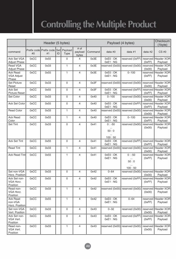
Controlling the Multiple ProductRS-232C
RJ-45
Header (5 bytes) Payload (4 bytes) Checksum (1byte)
command Prefix code #0
Prefix code #1
Set ID
Payload Type
# of payload
bytesCommand data #0 data #1 data #2 CS #0
Set Power 0xCC 0x33 0 4 0x10 0 : 0ff 1 : On
reserved (0x00) reserved (0x00)
Header XOR Payload
Ack Set Power
0xCC 0x55 0 4 0x10 0xE0 : OK 0xE1 : NG
reserved (0xFF) reserved (0xFF)
Header XOR Payload
Set Input Source
0xCC 0x33 0 4 0x11 0x30 : VGA1 0x40 : DVI1
0x50 : HDMI1 0x51 : HDMI2 0x52 : HDMI3
0x60 : Composite1
0x70 : YPbPr1 0x80 : Music
Port 0x90 : TV1
0xA0 : HDMI-UHD60
reserved (0x00) reserved (0x00)
Header XOR Payload
Ack Input Source
0xCC 0x55 0 4 0x11 0xE0 : OK 0xE1 : NG
reserved (0xFF) reserved (0xFF)
Header XOR Payload
Read Input Source
0xCC 0x33 1 4 0x11 reserved (0x00) reserved (0x00) reserved (0x00)
Header XOR Payload
Ack Read Input Source
0xCC 0x55 1 4 0x11 0xE0 : OK 0xE1 : NG
0x30 : VGA1 0x40 : DVI1
0x50 : HDMI1 0x51 : HDMI2 0x52 : HDMI3
0x60 : Composite1
0x70 : YPbPr1 0x80 : Music
Port 0x90 : TV1
0xA0 : HDMI-UHD60
reserved (0xFF)
Header XOR Payload
Set Screen Mute
0xCC 0x33 0 4 0x12 0 : mute off 1 : mute on
reserved (0x00) reserved (0x00)
Header XOR Payload
Ack Set Screen Mute
0xCC 0x55 0 4 0x12 0xE0 : OK 0xE1 : NG
reserved (0xFF) reserved (0xFF)
Header XOR Payload
Read Screen Mute
0xCC 0x33 1 4 0x12 reserved (0x00) reserved (0x00) reserved (0x00)
Header XOR Payload
Ack Read Screen Mute
0xCC 0x55 1 4 0x12 0xE0 : OK 0xE1 : NG
0 : mute off 1 : mute on
reserved (0xFF)
Header XOR Payload
RS-232C and RJ-45 Protocol

A2
Controlling the Multiple ProductRS-232C
RJ-45RS-232C
RJ-45
Header (5 bytes) Payload (4 bytes) Checksum (1byte)
command Prefix code #0
Prefix code #1
Set ID
Payload Type
# of payload
bytesCommand data #0 data #1 data #2 CS #0
Set Remote Controller Key
0xCC 0x33 0 4 0x14 0x08 : POWER 0x43 : MENU 0x0B : INPUT
0x40 : UP 0x41 : DOWN 0x07 : LEFT
0x06 : RIGHT 0x50 : OK
0x51 : INFO 0x52 : BACK 0x53 : EXIT
0x54 : VOL UP 0x55 : VOL
DOWN 0x56 : CH UP
0x57 : CH DOWN
0x58 : LAST 0x59 : -
0x5A : MUTE 0x5B : SLEEP
0x5C : FR 0x5D : PLAY
0x5E : FF 0x5F :
MULTIMEDIA 0x60 : PAUSE 0x61 : STOP
0x62 : FAV. CH 0x63 : WIDE
0x64 : AUDIO ONLY
0x80~0x89 : 0~9
reserved (0x00) reserved (0x00)
Header XOR Payload
Ack Set Remote Controller Key
0xCC 0x55 0 4 0x14 0xE0 : OK 0xE1 : NG
reserved (0xFF) reserved (0xFF)
Header XOR Payload
Set SleepTime
0xCC 0x33 0 4 0x19 0 : off 1 : 30 min 2 : 60 min 3 : 90 min
4 : 120 min 5 : 180 min
reserved (0x00) reserved (0x00)
Header XOR Payload
Ack Set SleepTime
0xCC 0x55 0 4 0x19 0xE0 : OK 0xE1 : NG
reserved (0x00) reserved (0x00)
Header XOR Payload
Read SleepTime
0xCC 0x33 1 4 0x19 reserved (0x00) reserved (0x00) reserved (0x00)
Header XOR Payload
Ack Read SleepTime
0xCC 0x55 1 4 0x19 0xE0 : OK 0xE1 : NG
0 : off 1 : 30 min 2 : 60 min 3 : 90 min
4 : 120 min 5 : 180 min
remain time to sleep in minute
Header XOR Payload
Set VGA Horz. Size
0xCC 0x33 0 4 0x20 0~255 reserved (0x00) reserved (0x00)
Header XOR Payload

A3
Controlling the Multiple ProductRS-232C
RJ-45
Header (5 bytes) Payload (4 bytes) Checksum (1byte)
command Prefix code #0
Prefix code #1
Set ID
Payload Type
# of payload
bytesCommand data #0 data #1 data #2 CS #0
Ack Set VGA Horz. Size
0xCC 0x55 0 4 0x20 0xE0 : OK 0xE1 : NG
reserved (0xFF) reserved (0xFF)
Header XOR Payload
Read VGA Horz. Size
0xCC 0x33 1 4 0x20 reserved (0x00) reserved (0x00) reserved (0x00)
Header XOR Payload
Ack Read VGA Horz. Size
0xCC 0x55 1 4 0x20 0xE0 : OK 0xE1 : NG
0~255 reserved (0xFF)
Header XOR Payload
_Set Color Temp. Reset
0xCC 0x33 0 4 0x21 reserved (0x00) reserved (0x00) reserved (0x00)
Header XOR Payload
Ack Set Color Temp.
0xCC 0x55 0 4 0x21 0xE0 : OK 0xE1 : NG
reserved (0xFF) reserved (0xFF)
Header XOR Payload
Set Picture Mode
0xCC 0x33 0 4 0x30 0 : Dynamic 1 : Normal
2 : Mild 3 : Usermild (Custoom)
4 : Standard (Natural) 5: Movie (Cinema) 6 : Game 7 : Vivid 8 : Sport
reserved (0x00) reserved (0x00)
Header XOR Payload
Ack Set Picture Mode
0xCC 0x55 0 4 0x30 0xE0 : OK 0xE1 : NG
reserved (0xFF) reserved (0xFF)
Header XOR Payload
Read Picture Mode
0xCC 0x33 1 4 0x30 reserved (0x00) reserved (0x00) reserved (0x00)
Header XOR Payload
Ack Read Picture Mode
0xCC 0x55 1 4 0x30 0xE0 : OK 0xE1 : NG
0 : Dynamic 1 : Normal
2 : Mild 3 : User
4 : Custom 5 : Standard
6: Movie 7 : Game 8 : Vivid 9 : Sport
reserved (0xFF)
Header XOR Payload
Set Brightness
0xCC 0x33 0 4 0x31 0~100 reserved (0x00) reserved (0x00)
Header XOR Payload
Ack Set Brightness
0xCC 0x55 0 4 0x31 0xE0 : OK 0xE1 : NG
reserved (0xFF) reserved (0xFF)
Header XOR Payload
Read Brightness
0xCC 0x33 1 4 0x31 reserved (0x00) reserved (0x00) reserved (0x00)
Header XOR Payload
Ack Read Brightness
0xCC 0x55 1 4 0x31 0xE0 : OK 0xE1 : NG
0~100 reserved (0xFF)
Header XOR Payload
Set Contrast 0xCC 0x33 0 4 0x32 0~100 reserved (0x00) reserved (0x00)
Header XOR Payload
Ack Set Contrast
0xCC 0x55 0 4 0x32 0xE0 : OK 0xE1 : NG
reserved (0xFF) reserved (0xFF)
Header XOR Payload
Read Contrast 0xCC 0x33 1 4 0x32 reserved (0x00) reserved (0x00) reserved (0x00)
Header XOR Payload
Ack Read Contrast
0xCC 0x55 1 4 0x32 0xE0 : OK 0xE1 : NG
0~100 reserved (0xFF)
Header XOR Payload

A4
Controlling the Multiple ProductRS-232C
RJ-45RS-232C
RJ-45
Header (5 bytes) Payload (4 bytes) Checksum (1byte)
command Prefix code #0
Prefix code #1
Set ID
Payload Type
# of payload
bytesCommand data #0 data #1 data #2 CS #0
Set Sharpness
0xCC 0x33 0 4 0x33 0~12 reserved (0x00) reserved (0x00)
Header XOR Payload
Ack Set Sharpness
0xCC 0x55 0 4 0x33 0xE0 : OK 0xE1 : NG
reserved (0xFF) reserved (0xFF)
Header XOR Payload
Read Sharpness
0xCC 0x33 1 4 0x33 reserved (0x00) reserved (0x00) reserved (0x00)
Header XOR Payload
Ack Read Sharpness
0xCC 0x55 1 4 0x33 0xE0 : OK 0xE1 : NG
0~20 reserved (0xFF)
Header XOR Payload
Set Backlight 0xCC 0x33 0 4 0x34 0~100 reserved (0x00) reserved (0x00)
Header XOR Payload
Ack Set Backlight
0xCC 0x55 0 4 0x34 0xE0 : OK 0xE1 : NG
reserved (0xFF) reserved (0xFF)
Header XOR Payload
Read Backlight
0xCC 0x33 1 4 0x34 reserved (0x00) reserved (0x00) reserved (0x00)
Header XOR Payload
Ack Read Backlight
0xCC 0x55 1 4 0x34 0xE0 : OK 0xE1 : NG
0~100 reserved (0xFF)
Header XOR Payload
Set Color Temp Mode
0xCC 0x33 0 4 0x35 0 : Cool (9300K) 1 : Medium
(6500K) 2 : Warm (5500K) 3 : User
(Custom) 4 : Natural 5 : 3200K
reserved (0x00) reserved (0x00)
Header XOR Payload
Ack Set Color Temp Mode
0xCC 0x55 0 4 0x35 0xE0 : OK 0xE1 : NG
reserved (0xFF) reserved (0xFF)
Header XOR Payload
Read Color Temp Mode
0xCC 0x33 1 4 0x35 reserved (0x00) reserved (0x00) reserved (0x00)
Header XOR Payload
Ack Read Color Temp Mode
0xCC 0x55 1 4 0x35 0xE0 : OK 0xE1 : NG
0 : Cool (9300K) 1 : Medium
(6500K) 2 : Warm (5500K) 3 : User
(Custom) 4 : Natural 5 : 3200K
reserved (0xFF)
Header XOR Payload
Set Color Temp Red Gain
0xCC 0x33 0 4 0x36 0 ~ 255 reserved (0x00) reserved (0x00)
Header XOR Payload
Ack Set Color Temp Red Gain
0xCC 0x55 0 4 0x36 0xE0 : OK 0xE1 : NG
reserved (0xFF) reserved (0xFF)
Header XOR Payload
Read Color Temp Red Gain
0xCC 0x33 1 4 0x36 reserved (0x00) reserved (0x00) reserved (0x00)
Header XOR Payload
Ack Read Color Temp Red Gain
0xCC 0x55 1 4 0x36 0xE0 : OK 0xE1 : NG
0 ~ 255 reserved (0xFF)
Header XOR Payload
Set Color Temp Green Gain
0xCC 0x33 0 4 0x37 0 ~ 255 reserved (0x00) reserved (0x00)
Header XOR Payload

A5
Controlling the Multiple ProductRS-232C
RJ-45
Header (5 bytes) Payload (4 bytes) Checksum (1byte)
command Prefix code #0
Prefix code #1
Set ID
Payload Type
# of payload
bytesCommand data #0 data #1 data #2 CS #0
Ack Set Color Temp Green Gain
0xCC 0x55 0 4 0x37 0xE0 : OK 0xE1 : NG
reserved (0xFF) reserved (0xFF)
Header XOR Payload
Read Color Temp Green Gain
0xCC 0x33 1 4 0x37 reserved (0x00) reserved (0x00) reserved (0x00)
Header XOR Payload
Ack Read Color Temp Green Gain
0xCC 0x55 1 4 0x37 0xE0 : OK 0xE1 : NG
0 ~ 255 reserved (0xFF)
Header XOR Payload
Set Color Temp Blue Gain
0xCC 0x33 0 4 0x38 0 ~ 255 reserved (0x00) reserved (0x00)
Header XOR Payload
Ack Set Color Temp Blue Gain
0xCC 0x55 0 4 0x38 0xE0 : OK 0xE1 : NG
reserved (0xFF) reserved (0xFF)
Header XOR Payload
Read Color Temp Blue Gain
0xCC 0x33 1 4 0x38 reserved (0x00) reserved (0x00) reserved (0x00)
Header XOR Payload
Ack Read Color Temp Blue Gain
0xCC 0x55 1 4 0x38 0xE0 : OK 0xE1 : NG
0 ~ 255 reserved (0xFF)
Header XOR Payload
Set VGA Adjust Auto Mode
0xCC 0x33 0 4 0x3A reserved (0x00) reserved (0x00) reserved (0x00)
Header XOR Payload
Ack Set VGA Adjust Auto Mode
0xCC 0x55 0 4 0x3A 0xE0 : OK 0xE1 : NG
reserved (0xFF) reserved (0xFF)
Header XOR Payload
Set VGA Adjust H Position
0xCC 0x33 0 4 0x3B 0~100 reserved (0x00) reserved (0x00)
Header XOR Payload
Ack Set VGA adjust H Position
0xCC 0x55 0 4 0x3B 0xE0 : OK 0xE1 : NG
reserved (0xFF) reserved (0xFF)
Header XOR Payload
Read VGA Adjust H Position
0xCC 0x33 1 4 0x3B reserved (0x00) reserved (0x00) reserved (0x00)
Header XOR Payload
Ack Read VGA Adjust H Position
0xCC 0x55 1 4 0x3B 0xE0 : OK 0xE1 : NG
0~100 reserved (0xFF)
Header XOR Payload
Set VGA Adjust V Position
0xCC 0x33 0 4 0x3C 0~100 reserved (0x00) reserved (0x00)
Header XOR Payload
Ack Set VGA Adjust V Position
0xCC 0x55 0 4 0x3C 0xE0 : OK 0xE1 : NG
reserved (0xFF) reserved (0xFF)
Header XOR Payload
Read VGA Adjust V Position
0xCC 0x33 1 4 0x3C reserved (0x00) reserved (0x00) reserved (0x00)
Header XOR Payload
Ack Read VGA Adjust V Position
0xCC 0x55 1 4 0x3C 0xE0 : OK 0xE1 : NG
0~100 reserved (0xFF)
Header XOR Payload
Set VGA Adjust Phase
0xCC 0x33 0 4 0x3E 0~100 reserved (0x00) reserved (0x00)
Header XOR Payload
A6
Controlling the Multiple ProductRS-232C
RJ-45RS-232C
RJ-45
Header (5 bytes) Payload (4 bytes) Checksum (1byte)
command Prefix code #0
Prefix code #1
Set ID
Payload Type
# of payload
bytesCommand data #0 data #1 data #2 CS #0
Ack Set VGA Adjust Phase
0xCC 0x55 0 4 0x3E 0xE0 : OK 0xE1 : NG
reserved (0xFF) reserved (0xFF)
Header XOR Payload
Read VGA Adjust Phase
0xCC 0x33 1 4 0x3E reserved (0x00) reserved (0x00) reserved (0x00)
Header XOR Payload
Ack Read VGA Adjust Phase
0xCC 0x55 1 4 0x3E 0xE0 : OK 0xE1 : NG
0~100 reserved (0xFF)
Header XOR Payload
Set Picture Reset
0xCC 0x33 0 4 0x3F reserved (0x00) reserved (0x00) reserved (0x00)
Header XOR Payload
Ack Set Picture Reset
0xCC 0x55 0 4 0x3F 0xE0 : OK 0xE1 : NG
reserved (0xFF) reserved (0xFF)
Header XOR Payload
Set Color 0xCC 0x33 0 4 0x40 0~100 reserved (0x00) reserved (0x00)
Header XOR Payload
Ack Set Color 0xCC 0x55 0 4 0x40 0xE0 : OK 0xE1 : NG
reserved (0xFF) reserved (0xFF)
Header XOR Payload
Read Color 0xCC 0x33 1 4 0x40 reserved (0x00) reserved (0x00) reserved (0x00)
Header XOR Payload
Ack Read Color
0xCC 0x55 1 4 0x40 0xE0 : OK 0xE1 : NG
0~100 reserved (0xFF)
Header XOR Payload
Set Tint 0xCC 0x33 0 4 0x41 0 : -50 ...
50 : 0 ...
100 : 50
reserved (0x00) reserved (0x00)
Header XOR Payload
Ack Set Tint 0xCC 0x55 0 4 0x41 0xE0 : OK 0xE1 : NG
reserved (0xFF) reserved (0xFF)
Header XOR Payload
Read Tint 0xCC 0x33 1 4 0x41 reserved (0x00) reserved (0x00) reserved (0x00)
Header XOR Payload
Ack Read Tint 0xCC 0x55 1 4 0x41 0xE0 : OK 0xE1 : NG
0 : -50 ...
50 : 0 ...
100 : 50
reserved (0xFF)
Header XOR Payload
Set non-VGA Horz. Position
0xCC 0x33 0 4 0x42 0~64 reserved (0x00) reserved (0x00)
Header XOR Payload
Ack Set non-VGA Horz. Position
0xCC 0x55 0 4 0x42 0xE0 : OK 0xE1 : NG
reserved (0xFF) reserved (0xFF)
Header XOR Payload
Read non-VGA Horz. Position
0xCC 0x33 1 4 0x42 reserved (0x00) reserved (0x00) reserved (0x00)
Header XOR Payload
Ack Read non-VGA Horz. Position
0xCC 0x55 1 4 0x42 0xE0 : OK 0xE1 : NG
0~64 reserved (0xFF)
Header XOR Payload
Set non-VGA Vert. Position
0xCC 0x33 0 4 0x43 0~32 reserved (0x00) reserved (0x00)
Header XOR Payload
Ack Set non-VGA Vert. Position
0xCC 0x55 0 4 0x43 0xE0 : OK 0xE1 : NG
reserved (0xFF) reserved (0xFF)
Header XOR Payload
Read non-VGA Vert. Position
0xCC 0x33 1 4 0x43 reserved (0x00) reserved (0x00) reserved (0x00)
Header XOR Payload

A7
Controlling the Multiple ProductRS-232C
RJ-45
Header (5 bytes) Payload (4 bytes) Checksum (1byte)
command Prefix code #0
Prefix code #1
Set ID
Payload Type
# of payload
bytesCommand data #0 data #1 data #2 CS #0
Ack Read non-VGA Vert. Position
0xCC 0x55 1 4 0x43 0xE0 : OK 0xE1 : NG
0~32 reserved (0xFF)
Header XOR Payload
Set non-VGA Horz. Size
0xCC 0x33 0 4 0x44 0~100 reserved (0x00) reserved (0x00)
Header XOR Payload
Ack Set non-VGA Horz. Size
0xCC 0x55 0 4 0x44 0xE0 : OK 0xE1 : NG
reserved (0xFF) reserved (0xFF)
Header XOR Payload
Read non-VGA Horz. Size
0xCC 0x33 1 4 0x44 reserved (0x00) reserved (0x00) reserved (0x00)
Header XOR Payload
Ack Read non-VGA Horz. Size
0xCC 0x55 1 4 0x44 0xE0 : OK 0xE1 : NG
0~100 reserved (0xFF)
Header XOR Payload
Set non-VGA Vert. Size
0xCC 0x33 0 4 0x45 0~100 reserved (0x00) reserved (0x00)
Header XOR Payload
Ack Set non-VGA Vert. Size
0xCC 0x55 0 4 0x45 0xE0 : OK 0xE1 : NG
reserved (0xFF) reserved (0xFF)
Header XOR Payload
Read non-VGA Vert. Size
0xCC 0x33 1 4 0x45 reserved (0x00) reserved (0x00) reserved (0x00)
Header XOR Payload
Ack Read non-VGA Vert. Size
0xCC 0x55 1 4 0x45 0xE0 : OK 0xE1 : NG
0~100 reserved (0xFF)
Header XOR Payload
Set Color Temp Red Offset
0xCC 0x33 0 4 0x46 0 ~ 255 reserved (0x00) reserved (0x00)
Header XOR Payload
Ack Set Color Temp Red Offset
0xCC 0x55 0 4 0x46 0xE0 : OK 0xE1 : NG
reserved (0xFF) reserved (0xFF)
Header XOR Payload
Read Color Temp Red Offset
0xCC 0x33 1 4 0x46 reserved (0x00) reserved (0x00) reserved (0x00)
Header XOR Payload
Ack Read Color Temp Red Offset
0xCC 0x55 1 4 0x46 0xE0 : OK 0xE1 : NG
0 ~ 255 reserved (0xFF)
Header XOR Payload
Set Color Temp Green Offset
0xCC 0x33 0 4 0x47 0 ~ 255 reserved (0x00) reserved (0x00)
Header XOR Payload
Ack Set Color Temp Green Offset
0xCC 0x55 0 4 0x47 0xE0 : OK 0xE1 : NG
reserved (0xFF) reserved (0xFF)
Header XOR Payload
Read Color Temp Green Offset
0xCC 0x33 1 4 0x47 reserved (0x00) reserved (0x00) reserved (0x00)
Header XOR Payload
Ack Read Color Temp Green Offset
0xCC 0x55 1 4 0x47 0xE0 : OK 0xE1 : NG
0 ~ 255 reserved (0xFF)
Header XOR Payload
Set Color Temp Blue Offset
0xCC 0x33 0 4 0x48 0 ~ 255 reserved (0x00) reserved (0x00)
Header XOR Payload

A8
Controlling the Multiple ProductRS-232C
RJ-45RS-232C
RJ-45
Header (5 bytes) Payload (4 bytes) Checksum (1byte)
command Prefix code #0
Prefix code #1
Set ID
Payload Type
# of payload
bytesCommand data #0 data #1 data #2 CS #0
Ack Set Color Temp Blue Offset
0xCC 0x55 0 4 0x48 0xE0 : OK 0xE1 : NG
reserved (0xFF) reserved (0xFF)
Header XOR Payload
Read Color Temp Blue Offset
0xCC 0x33 1 4 0x48 reserved (0x00) reserved (0x00) reserved (0x00)
Header XOR Payload
Ack Read Color Temp Blue Offset
0xCC 0x55 1 4 0x48 0xE0 : OK 0xE1 : NG
0 ~ 255 reserved (0xFF)
Header XOR Payload
Set Dynamic Contrast
0xCC 0x33 0 4 0x4B 0 : Off 1 : Low
2 : Medium 3 : High
reserved (0x00) reserved (0x00)
Header XOR Payload
Ack Set Dynamic Contrast
0xCC 0x55 0 4 0x4B 0xE0 : OK 0xE1 : NG
reserved (0xFF) reserved (0xFF)
Header XOR Payload
Read Dynamic Contrast
0xCC 0x33 1 4 0x4B reserved (0x00) reserved (0x00) reserved (0x00)
Header XOR Payload
Ack Read Dynamic Contrast
0xCC 0x55 1 4 0x4B 0xE0 : OK 0xE1 : NG
0 : Off 1 : Low
2 : Medium 3 : High
reserved (0xFF)
Header XOR Payload
Set Local Dimming
0xCC 0x33 0 4 0x4C 0 : Off 1 : On
reserved (0x00) reserved (0x00)
Header XOR Payload
Ack Set Local Dimming
0xCC 0x55 0 4 0x4C 0xE0 : OK 0xE1 : NG
reserved (0xFF) reserved (0xFF)
Header XOR Payload
Read Local Dimming
0xCC 0x33 1 4 0x4C reserved (0x00) reserved (0x00) reserved (0x00)
Header XOR Payload
Ack Read Local Dimming
0xCC 0x55 1 4 0x4C 0xE0 : OK 0xE1 : NG
0 : Off 1 : On
reserved (0xFF)
Header XOR Payload
Set Noise Reduction
0xCC 0x33 0 4 0x4D 0 : Off 1 : Low
2 : Medium 3 : High
reserved (0x00) reserved (0x00)
Header XOR Payload
Ack Set Noise Reduction
0xCC 0x55 0 4 0x4D 0xE0 : OK 0xE1 : NG
reserved (0xFF) reserved (0xFF)
Header XOR Payload
Read Noise Reduction
0xCC 0x33 1 4 0x4D reserved (0x00) reserved (0x00) reserved (0x00)
Header XOR Payload
Ack Read Noise Reduction
0xCC 0x55 1 4 0x4D 0xE0 : OK 0xE1 : NG
0 : Off 1 : Low
2 : Medium 3 : High
reserved (0xFF)
Header XOR Payload
Set Digital NR 0xCC 0x33 0 4 0x4E 0 : Off 1 : Low
2 : Medium 3 : High
reserved (0x00) reserved (0x00)
Header XOR Payload
Ack Set Digital NR
0xCC 0x55 0 4 0x4E 0xE0 : OK 0xE1 : NG
reserved (0xFF) reserved (0xFF)
Header XOR Payload
Read Digital NR
0xCC 0x33 1 4 0x4E reserved (0x00) reserved (0x00) reserved (0x00)
Header XOR Payload

A9
Controlling the Multiple ProductRS-232C
RJ-45
Header (5 bytes) Payload (4 bytes) Checksum (1byte)
command Prefix code #0
Prefix code #1
Set ID
Payload Type
# of payload
bytesCommand data #0 data #1 data #2 CS #0
Ack Read Digital NR
0xCC 0x55 1 4 0x4E 0xE0 : OK 0xE1 : NG
0 : Off 1 : Low
2 : Medium 3 : High
reserved (0xFF)
Header XOR Payload
Set Film Mode
0xCC 0x33 0 4 0x4F 0 : Off 1 : Auto
reserved (0x00) reserved (0x00)
Header XOR Payload
Ack Set Film Mode
0xCC 0x55 0 4 0x4F 0xE0 : OK 0xE1 : NG
reserved (0xFF) reserved (0xFF)
Header XOR Payload
Read Film Mode
0xCC 0x33 1 4 0x4F reserved (0x00) reserved (0x00) reserved (0x00)
Header XOR Payload
Ack Read Film Mode
0xCC 0x55 1 4 0x4F 0xE0 : OK 0xE1 : NG
0 : Off 1 : Auto
reserved (0xFF)
Header XOR Payload
Set Balance 0xCC 0x33 0 4 0x56 0 : L50 ~
49 : L1 50 : 0
51 : R1 ~
100 : R50
reserved (0x00) reserved (0x00)
Header XOR Payload
Ack Set Balance
0xCC 0x55 0 4 0x56 0xE0 : OK 0xE1 : NG
reserved (0xFF) reserved (0xFF)
Header XOR Payload
Read Balance 0xCC 0x33 1 4 0x56 reserved (0x00) reserved (0x00) reserved (0x00)
Header XOR Payload
Ack Read Balance
0xCC 0x55 1 4 0x56 0xE0 : OK 0xE1 : NG
0 : L50 ~
49 : L1 50 : 0
51 : R1 ~
100 : R50
reserved (0xFF)
Header XOR Payload
Set Volume 0xCC 0x33 0 4 0x58 0~100 reserved (0x00) reserved (0x00)
Header XOR Payload
Ack Set Volume
0xCC 0x55 0 4 0x58 0xE0 : OK 0xE1 : NG
reserved (0xFF) reserved (0xFF)
Header XOR Payload
Read Volume 0xCC 0x33 1 4 0x58 reserved (0x00) reserved (0x00) reserved (0x00)
Header XOR Payload
Ack Read Volume
0xCC 0x55 1 4 0x58 0xE0 : OK 0xE1 : NG
0~100 reserved (0xFF)
Header XOR Payload
Set Sound Reset
0xCC 0x33 0 4 0x59 reserved (0x00) reserved (0x00) reserved (0x00)
Header XOR Payload
Ack Set Sound Reset
0xCC 0x55 0 4 0x59 0xE0 : OK 0xE1 : NG
reserved (0xFF) reserved (0xFF)
Header XOR Payload
Set XinemaSound 3D
0xCC 0x33 0 4 0x60 0: Off 1: On
reserved (0x00) reserved (0x00)
Header XOR Payload
Ack Set XinemaSound 3D
0xCC 0x55 0 4 0x60 0xE0 : OK 0xE1 : NG
reserved (0xFF) reserved (0xFF)
Header XOR Payload
Read XinemaSound 3D
0xCC 0x33 1 4 0x60 reserved (0x00) reserved (0x00) reserved (0x00)
Header XOR Payload
Ack Read XinemaSound 3D
0xCC 0x55 1 4 0x60 0xE0 : OK 0xE1 : NG
0: Off 1: On
reserved (0xFF)
Header XOR Payload

A10
Controlling the Multiple ProductRS-232C
RJ-45RS-232C
RJ-45
Header (5 bytes) Payload (4 bytes) Checksum (1byte)
command Prefix code #0
Prefix code #1
Set ID
Payload Type
# of payload
bytesCommand data #0 data #1 data #2 CS #0
Set XinemaSound Leveler
0xCC 0x33 0 4 0x61 0: Off 1: On
reserved (0x00) reserved (0x00)
Header XOR Payload
Ack Set XinemaSound Leveler
0xCC 0x55 0 4 0x61 0xE0 : OK 0xE1 : NG
reserved (0xFF) reserved (0xFF)
Header XOR Payload
Read XinemaSound Leveler
0xCC 0x33 1 4 0x61 reserved (0x00) reserved (0x00) reserved (0x00)
Header XOR Payload
Ack Read XinemaSound Leveler
0xCC 0x55 1 4 0x61 0xE0 : OK 0xE1 : NG"
0: Off 1: On
reserved (0xFF)
Header XOR Payload
Set Bass 0xCC 0x33 0 4 0x62 0: -12 …
12 : 0 ...
24: 12
reserved (0x00) reserved (0x00)
Header XOR Payload
Ack Set Bass 0xCC 0x55 0 4 0x62 0xE0 : OK 0xE1 : NG
reserved (0xFF) reserved (0xFF)
Header XOR Payload
Read Bass 0xCC 0x33 1 4 0x62 reserved (0x00) reserved (0x00) reserved (0x00)
Header XOR Payload
Ack Read Bass
0xCC 0x55 1 4 0x62 0xE0 : OK 0xE1 : NG
0: -12 …
12 : 0 ...
24: 12
reserved (0xFF)
Header XOR Payload
Set Treble 0xCC 0x33 0 4 0x63 0: -12 …
12 : 0 ...
24: 12
reserved (0x00) reserved (0x00)
Header XOR Payload
Ack Set Treble
0xCC 0x55 0 4 0x63 0xE0 : OK 0xE1 : NG
reserved (0xFF) reserved (0xFF)
Header XOR Payload
Read Treble 0xCC 0x33 1 4 0x63 reserved (0x00) reserved (0x00) reserved (0x00)
Header XOR Payload
Ack Read Treble
0xCC 0x55 1 4 0x63 0xE0 : OK 0xE1 : NG
0: -12 …
12 : 0 ...
24: 12
reserved (0xFF)
Header XOR Payload
Set Lip Sync 0xCC 0x33 0 4 0x64 0~5 reserved (0x00) reserved (0x00)
Header XOR Payload
Ack Set Lip Sync
0xCC 0x55 0 4 0x64 0xE0 : OK 0xE1 : NG
reserved (0xFF) reserved (0xFF)
Header XOR Payload
Read Lip Sync
0xCC 0x33 1 4 0x64 reserved (0x00) reserved (0x00) reserved (0x00)
Header XOR Payload
Ack Read Lip Sync
0xCC 0x55 1 4 0x64 0xE0 : OK 0xE1 : NG
0~5 reserved (0xFF)
Header XOR Payload
Set Speakers 0xCC 0x33 0 4 0x65 0 : Off 1 : On
reserved (0x00) reserved (0x00)
Header XOR Payload
Ack Set Speakers
0xCC 0x55 0 4 0x65 0xE0 : OK 0xE1 : NG
reserved (0xFF) reserved (0xFF)
Header XOR Payload
Read Speakers
0xCC 0x33 1 4 0x65 reserved (0x00) reserved (0x00) reserved (0x00)
Header XOR Payload

A11
Controlling the Multiple ProductRS-232C
RJ-45
Header (5 bytes) Payload (4 bytes) Checksum (1byte)
command Prefix code #0
Prefix code #1
Set ID
Payload Type
# of payload
bytesCommand data #0 data #1 data #2 CS #0
Ack Read Speakers
0xCC 0x55 1 4 0x65 0xE0 : OK 0xE1 : NG
0 : Off 1 : On
reserved (0xFF)
Header XOR Payload
Set Audio Only
0xCC 0x33 0 4 0x66 0 : Off 1 : On
reserved (0x00) reserved (0x00)
Header XOR Payload
Ack Set Audio Only
0xCC 0x55 0 4 0x66 0xE0 : OK 0xE1 : NG
reserved (0xFF) reserved (0xFF)
Header XOR Payload
Read Audio Only
0xCC 0x33 1 4 0x66 reserved (0x00) reserved (0x00) reserved (0x00)
Header XOR Payload
Ack Read Audio Only
0xCC 0x55 1 4 0x66 0xE0 : OK 0xE1 : NG
0 : Off 1 : On
reserved (0xFF)
Header XOR Payload
Set Digital Audio Out
0xCC 0x33 0 4 0x67 0 : Off 1 : Dolby 2 : PCM
reserved (0x00) reserved (0x00)
Header XOR Payload
Ack Set Digital Audio Out
0xCC 0x55 0 4 0x67 0xE0 : OK 0xE1 : NG
reserved (0xFF) reserved (0xFF)
Header XOR Payload
Read Digital Audio Out
0xCC 0x33 1 4 0x67 reserved (0x00) reserved (0x00) reserved (0x00)
Header XOR Payload
Ack Read Digital Audio Out
0xCC 0x55 1 4 0x67 0xE0 : OK 0xE1 : NG
0 : Off 1 : Dolby 2 : PCM
reserved (0xFF)
Header XOR Payload
Set Analog Audio Out
0xCC 0x33 0 4 0x68 0 : Fixed 1 : Variable
reserved (0x00) reserved (0x00)
Header XOR Payload
Ack Set Analog Audio Out
0xCC 0x55 0 4 0x68 0xE0 : OK 0xE1 : NG
reserved (0xFF) reserved (0xFF)
Header XOR Payload
Read Analog Audio Out
0xCC 0x33 1 4 0x68 reserved (0x00) reserved (0x00) reserved (0x00)
Header XOR Payload
Ack Read Analog Audio Out
0xCC 0x55 1 4 0x68 0xE0 : OK 0xE1 : NG
0 : Fixed 1 : Variable
reserved (0xFF)
Header XOR Payload
Set Equalizer 0xCC 0x33 0 4 0x69 0 : 120Hz 1 : 500Hz 2: 1.5KHz 3: 5KHz
4: 10KHz
0 : -12 ...
12: 0 ...
24: 12
reserved (0x00)
Header XOR Payload
Ack Set Equalizer
0xCC 0x55 0 4 0x69 0xE0 : OK 0xE1 : NG
0 : 120Hz 1 : 500Hz 2: 1.5KHz 3: 5KHz
4: 10KHz
reserved (0xFF)
Header XOR Payload
Read Equalizer
0xCC 0x33 1 4 0x69 0 : 120Hz 1 : 500Hz 2: 1.5KHz 3: 5KHz
4: 10KHz
reserved (0x00) reserved (0x00)
Header XOR Payload
Ack Read Equalizer
0xCC 0x55 1 4 0x69 0xE0 : OK 0xE1 : NG
0 : 120Hz 1 : 500Hz 2: 1.5KHz 3: 5KHz
4: 10KHz
0 : -12 ...
12: 0 ...
24: 12
Header XOR Payload

A12
Controlling the Multiple ProductRS-232C
RJ-45RS-232C
RJ-45
Header (5 bytes) Payload (4 bytes) Checksum (1byte)
command Prefix code #0
Prefix code #1
Set ID
Payload Type
# of payload
bytesCommand data #0 data #1 data #2 CS #0
Set OSD Language
0xCC 0x33 0 4 0x70 0 : English 1 : Spanish 2 : French 3 : Italian
4 : Deutsch 5 : Polski
6 : Portuques 7 : Chinese
8 : Japanese 9 : Korean
reserved (0x00) reserved (0x00)
Header XOR Payload
Ack Set OSD Language
0xCC 0x55 0 4 0x70 0xE0 : OK 0xE1 : NG
reserved (0xFF) reserved (0xFF)
Header XOR Payload
Read OSD Language
0xCC 0x33 1 4 0x70 reserved (0x00) reserved (0x00) reserved (0x00)
Header XOR Payload
Ack Read OSD Language
0xCC 0x55 1 4 0x70 0xE0 : OK 0xE1 : NG
0 : English 1 : Spanish 2 : French 3 : Italian
4 : Deutsch 5 : Polski
6 : Portuques 7 : Chinese
8 : Japanese 9 : Korean
reserved (0xFF)
Header XOR Payload
Set ID Setup 0xCC 0x33 0 4 0x73 1~100 reserved (0x00) reserved (0x00)
Header XOR Payload
Ack Set ID Setup
0xCC 0x55 0 4 0x73 0xE0 : OK 0xE1 : NG
reserved (0xFF) reserved (0xFF)
Header XOR Payload
Set Power Indicator
0xCC 0x33 0 4 0x76 0 : Off 1 : On
reserved (0x00) reserved (0x00)
Header XOR Payload
Ack Set Power Indicator
0xCC 0x55 0 4 0x76 0xE0 : OK 0xE1 : NG
reserved (0xFF) reserved (0xFF)
Header XOR Payload
Read Power Indicator
0xCC 0x33 1 4 0x76 reserved (0x00) reserved (0x00) reserved (0x00)
Header XOR Payload
Ack Read Power Indicator
0xCC 0x55 1 4 0x76 0xE0 : OK 0xE1 : NG
0 : Off 1 : On
reserved (0xFF)
Header XOR Payload
Set Factory Reset
0xCC 0x33 0 4 0x79 reserved (0x00) reserved (0x00) reserved (0x00)
Header XOR Payload
Ack Set Factory Reset
0xCC 0x55 0 4 0x79 0xE0 : OK 0xE1 : NG
reserved (0xFF) reserved (0xFF)
Header XOR Payload
Read Set ID 0xCC 0x33 1 4 0x90 reserved (0x00) reserved (0x00) reserved (0x00)
Header XOR Payload
Ack Read Set ID
0xCC 0x55 1 4 0x90 0xE0 : OK 0xE1 : NG
1~100 reserved (0xFF)
Header XOR Payload
Read F/W Version
0xCC 0x33 1 4 0x91 reserved (0x00) reserved (0x00) reserved (0x00)
Header XOR Payload
Ack Read F/W Version
0xCC 0x55 1 4 0x91 0xE0 : OK 0xE1 : NG
F/WLeft part F/W Right part
Header XOR Payload
Read Input Resolution
0xCC 0x33 1 4 0xA3 reserved (0x00) reserved (0x00) reserved (0x00)
Header XOR Payload

A13
Controlling the Multiple ProductRS-232C
RJ-45
Header (5 bytes) Payload (4 bytes) Checksum (1byte)
command Prefix code #0
Prefix code #1
Set ID
Payload Type
# of payload
bytesCommand data #0 data #1 data #2 CS #0
Ack Read Input Resolution
0xCC 0x55 1 4 0xA3 Hwidth bit(11:4)
bit(7:4) Hwidth bit(3:0)
bit(3:0) Vheight bit(11:8)
Vheight bit(7:0)
Header XOR Payload
Set CEC 0xCC 0x33 0 4 0xA5 0 : Off 1 : On
reserved (0x00) reserved (0x00)
Header XOR Payload
Ack Set CEC 0xCC 0x55 0 4 0xA5 0xE0 : OK 0xE1 : NG
reserved (0xFF) reserved (0xFF)
Header XOR Payload
Read CEC 0xCC 0x33 1 4 0xA6 reserved (0x00) reserved (0x00) reserved (0x00)
Header XOR Payload
Ack Read CEC
0xCC 0x55 1 4 0xA6 0xE0 : OK 0xE1 : NG
0 : Off 1 : On
reserved (0xFF)
Header XOR Payload
Set CEC Device Search
0xCC 0x33 0 4 0xA8 reserved (0x00) reserved (0x00) reserved (0x00)
Header XOR Payload
Ack Set CEC Device Search
0xCC 0x55 0 4 0xA8 0xE0 : OK 0xE1 : NG
reserved (0xFF) reserved (0xFF)
Header XOR Payload
Read CEC Devices
0xCC 0x33 1 4 0xA8 reserved (0x00) reserved (0x00) reserved (0x00)
Header XOR Payload
Ack CEC Device
0xCC 0x55 1 4+ 0xA8 bit(7:4) : 0 for OK, others NG bit(3:0) : device
number
byte1 : LA of device1 byte2~N : OSD name of
device1(0 for end) byteN+1 : LA of device2
byteN+2~M : OSD name of device2(0 for end)
…
Header XOR Payload
Set Reset All Settings
0xCC 0x33 0 4 0xAB reserved (0x00) reserved (0x00) reserved (0x00)
Header XOR Payload
Ack Set Reset All Settings
0xCC 0x55 0 4 0xAB 0xE0 : OK 0xE1 : NG
reserved (0xFF) reserved (0xFF)
Header XOR Payload
Set DHCP 0xCC 0x33 0 4 0xAC reserved (0x00) reserved (0x00) reserved (0x00)
Header XOR Payload
Ack Set DHCP
0xCC 0x55 0 4 0xAC 0xE0 : OK 0xE1 : NG
reserved (0xFF) reserved (0xFF)
Header XOR Payload
Set Static IP 0xCC 0x33 0 21 0xAD 20 bytes (IP + Subnet Mask + Gateway + DNS1 + DNS2)
Header XOR Payload
Ack Set Static IP
0xCC 0x55 0 4 0xAD 0xE0 : OK 0xE1 : NG
reserved (0xFF) reserved (0xFF)
Header XOR Payload
Read Static IP 0xCC 0x33 1 4 0xAD reserved (0x00) reserved (0x00) reserved (0x00)
Header XOR Payload
Ack Read Static IP
0xCC 0x55 1 22 0xAD 0xE0 : OK 0xE1 : NG
20 bytes (IP + Subnet Mask + Gatway + DNS1
+ DNS2)
Header XOR Payload
Read Ethernet Status
0xCC 0x33 1 4 0xAE reserved (0x00) reserved (0x00) reserved (0x00)
Header XOR Payload
Ack Read Ethernet Status
0xCC 0x55 1 4 0xAE 0xE0 : OK 0xE1 : NG
0: Disconnected 1: Connected
0: DHCP 1: Static
IP
Header XOR Payload
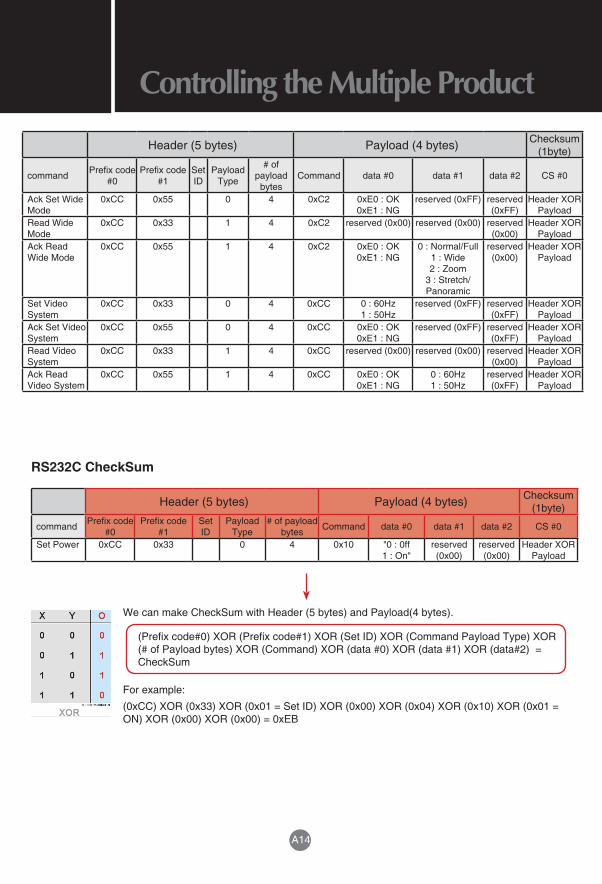
Set Wide Mode
0xCC 0x33 0 4 0xC2 0 : Normal/Full 1 : Wide 2 : Zoom
3 : Stretch/Panoramic
reserved (0x00) reserved (0x00)
Header XOR Payload
A14
Controlling the Multiple ProductRS-232C
RJ-45
Header (5 bytes) Payload (4 bytes) Checksum (1byte)
command Prefix code #0
Prefix code #1
Set ID
Payload Type
# of payload
bytesCommand data #0 data #1 data #2 CS #0
Ack Set Wide Mode
0xCC 0x55 0 4 0xC2 0xE0 : OK 0xE1 : NG
reserved (0xFF) reserved (0xFF)
Header XOR Payload
Read Wide Mode
0xCC 0x33 1 4 0xC2 reserved (0x00) reserved (0x00) reserved (0x00)
Header XOR Payload
Ack Read Wide Mode
0xCC 0x55 1 4 0xC2 0xE0 : OK 0xE1 : NG
0 : Normal/Full 1 : Wide 2 : Zoom
3 : Stretch/Panoramic
reserved (0x00)
Header XOR Payload
Set Video System
0xCC 0x33 0 4 0xCC 0 : 60Hz 1 : 50Hz
reserved (0xFF) reserved (0xFF)
Header XOR Payload
Ack Set Video System
0xCC 0x55 0 4 0xCC 0xE0 : OK 0xE1 : NG
reserved (0xFF) reserved (0xFF)
Header XOR Payload
Read Video System
0xCC 0x33 1 4 0xCC reserved (0x00) reserved (0x00) reserved (0x00)
Header XOR Payload
Ack Read Video System
0xCC 0x55 1 4 0xCC 0xE0 : OK 0xE1 : NG
0 : 60Hz 1 : 50Hz
reserved (0xFF)
Header XOR Payload
RS232C CheckSum
Header (5 bytes) Payload (4 bytes) Checksum (1byte)
command Prefix code #0
Prefix code #1
Set ID
Payload Type
# of payload bytes Command data #0 data #1 data #2 CS #0
Set Power 0xCC 0x33 0 4 0x10 "0 : 0ff 1 : On"
reserved (0x00)
reserved (0x00)
Header XOR Payload
We can make CheckSum with Header (5 bytes) and Payload(4 bytes).
(Prefix code#0) XOR (Prefix code#1) XOR (Set ID) XOR (Command Payload Type) XOR (# of Payload bytes) XOR (Command) XOR (data #0) XOR (data #1) XOR (data#2) = CheckSum
For example:
(0xCC) XOR (0x33) XOR (0x01 = Set ID) XOR (0x00) XOR (0x04) XOR (0x10) XOR (0x01 = ON) XOR (0x00) XOR (0x00) = 0xEB

Make sure to read the Safety Precautions before using the product.Keep the Owner's Manual(CD) in an accessible place for future reference.The model and serial number of the SET is located on the back and one side of the SET. Record it below should you ever need service.
MODEL
SERIALTemporary noise is normal when powering ON or OFF this device.
For detail information about ISF, please refer web site:http://www.imagingscience.com/