p automatizaÇÕes para portas basculantes de molas … · installation manual english thank you...
TRANSCRIPT
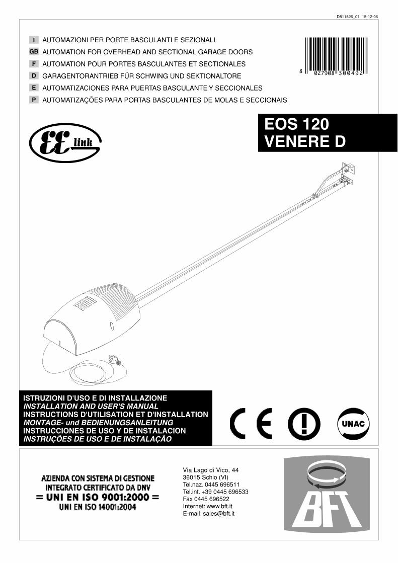
ISTRUZIONI D'USO E DI INSTALLAZIONEINSTALLATION AND USER'S MANUALINSTRUCTIONS D'UTILISATION ET D'INSTALLATIONMONTAGE- und BEDIENUNGSANLEITUNGINSTRUCCIONES DE USO Y DE INSTALACIONINSTRUÇÕES DE USO E DE INSTALAÇÃO
I
GB
F
D
E
P
Via Lago di Vico, 4436015 Schio (VI)Tel.naz. 0445 696511Tel.int. +39 0445 696533Fax 0445 696522Internet: www.bft.itE-mail: [email protected]
EOS 120VENERE D
AUTOMAZIONI PER PORTE BASCULANTI E SEZIONALI
AUTOMATION FOR OVERHEAD AND SECTIONAL GARAGE DOORS
AUTOMATION POUR PORTES BASCULANTES ET SECTIONALES
GARAGENTORANTRIEB FÜR SCHWING UND SEKTIONALTORE
AUTOMATIZACIONES PARA PUERTAS BASCULANTE Y SECCIONALES
AUTOMATIZAÇÕES PARA PORTAS BASCULANTES DE MOLAS E SECCIONAIS
D811526_01 15-12-06
8 027908 3 0 0 4 9 2

INSTALLATION MANUAL ENGLISH
Thank you for buying this product, our company is sure that you will be more than satisfied with the product’s performance. The product is supplied with a “Warnings” leaflet and an “Instruction booklet”. These should both be read carefully as they provide important information about safety, installation, operation and maintenance. This product complies with the recognised technical standards and safety regulations. We declare that this product is in conformity with the following European Directives: 89/336/EEC, 73/23/EEC, 98/37/EEC, 99/05/EEC (and subsequent amendments).
1) GENERAL SAFETYWARNING! An incorrect installation or improper use of the product
can cause damage to persons, animals or things.• The “Warnings” leaflet and “Instruction booklet” supplied with
this product should be read carefully as they provide important information about safety, installation, use and maintenance.
• Scrap packing materials (plastic, cardboard, polystyrene etc) according to the provisions set out by current standards. Keep nylon or polystyrene bags out of children’s reach.
• Keep the instructions together with the technical brochure for future reference.
• This product was exclusively designed and manufactured for the use specified in the present documentation. Any other use not specified in this documentation could damage the product and be dangerous.
• The Company declines all responsibility for any consequences resulting from improper use of the product, or use which is different from that expected and specified in the present documentation.
• Do not install the product in explosive atmosphere.• The construction components of this product must comply with
the following European Directives: 89/336/CEE, 73/23/EEC, 98/37/EEC and subsequent amendments. As for all non EEC countries, the abovementioned standards as well as the current national standards should be respected in order to achieve a good safety level.
• The Company declines all responsibility for any consequences resulting from failure to observe Good Technical Practice when constructing closing structures (door, gates etc.), as well as from any deformationwhich might occur during use.
• The installation must comply with the provisions set out by the fol-lowingEuropean Directives: 89/336/CEE, 73/23/EEC, 98/37/EEC and subsequent amendments.
• Disconnect the electrical power supply before carrying out any work on the installation. Also disconnect any buffer batteries, if fitted.
• Fit an omnipolar or magnetothermal switch on the mains power supply, having a contact opening distance equal to or greater than 3,5 mm.
• Check that a differential switch with a 0.03A threshold is fitted just before the power supply mains.
• Check that earthing is carried out correctly: connect all metal parts for closure (doors, gates etc.) and all system components provided with an earth terminal.
• Fit all the safety devices (photocells, electric edges etc.) which are needed to protect the area from any danger caused by squashing, conveying and shearing.
• Position at least one luminous signal indication device (blinker) where it can be easily seen, and fix a Warning sign to the structure.
• The Company declines all responsibility with respect to the automation safety and correct operation when other manufacturers’ components are used.
• Only use original parts for any maintenance or repair opera-tion.
• Do not modify the automation components, unless explicitly authorised by the company.
• Instruct the product user about the control systems provided and the manual opening operation in case of emergency.
• Do not allow persons or children to remain in the automation operation area.
• Keep radio control or other control devices out of children’s reach, in order to avoid unintentional automation activation.
• The user must avoid any attempt to carry out work or repair on the automation system, and always request the assistance of qualified personnel.
• Anything which is not expressly provided for in the present instruc-tions, is not allowed.
• Installation must be carried out using the safety devices and controls prescribed by the EN 12978 Standard.
• Fit any fixed control within sight of the door but away from moving parts, higher than 1.5 m.
• Add a label bearing the following notices: “Keep children away from the moving door”. “WARNING: risk of squashing”. Regularly check that the door reverses its movement when colliding
with an obstacle 50 mm away from the floor and, if necessary, set it correctly.
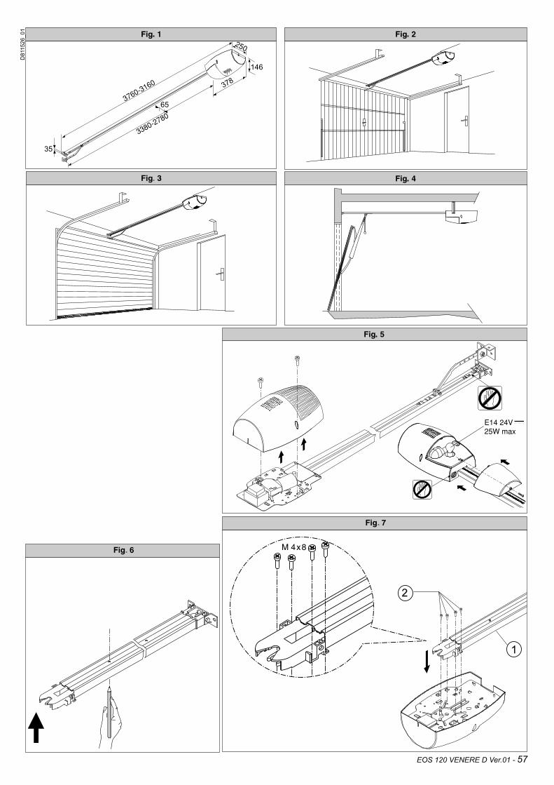
2) GENERAL OUTLINEThe EOS 120 system is suitable for motorising sectional doors (fig. 3), protruding fully retracting spring-operated overhead doors (fig. 2) and counterweight overhead doors provided with an appropriate towing arm (fig. 4). The overhead door must not be higher than 3 metres. Its easy installation allows fast fitting without needing the door to be modified. The irreversible gearmotor keeps the door locked in the closing position.
3) TECHNICAL SPECIFICATIONS3.1) ActuatorPower supply:.....................230V~±10%, 50/60Hz single-phase (*)~±10%, 50/60Hz single-phase (*)±10%, 50/60Hz single-phase (*)Motor voltage:...........................................................................24VMax. power absorbed from mains:.........................................236WLubrication:.........................................................permanent greaseTowing and pushing force:....................................................1200NWorking stroke:.......TRACK L.=2900 working stroke=2400 mm(**)..............................TRACK L.=3500 working stroke=3000 mm(***)Average speed:...................................................................5 m/minImpact reaction:...............integrated torque limiter on control panelManoeuvres in 24 hours:...........................................................100Limit switch:...........................................Electronic with ENCODERCourtesy light:........................................24V~ 25W max, E14 bulb~ 25W max, E14 bulb25W max, E14 bulbWorking temperature:...............................................-15°C / +60°CDegree of protection:...............................................................IPX0Motor head weight:....................................................................5kgNoise level:.......................................................................<70dB(A)Dimensions:.......................................................................see fig.1(*) Available in all mains voltages.(**)By turning the motor head by 90° (Fig.11) the useful stroke will be 2580 mm.(***) By turning the motor head by 90° (Fig.11) the useful stroke will be 3180 mm.
4) ACTUATOR INSTALLATION4.1) Preliminary checks• Check that the door is balanced.• Check that the door slides smoothly along its entire travel.• If the door has not been newly installed, check the wear condition
of all its components.• Repair or replace faulty or worn parts.• The automation reliability and safety are directly influenced by
the state of the door structure.• Before fitting the motor, remove any superfluous ropes or chains
and disable any unnecessary appliances.
4.2) FITTINGAfter unpacking, dispose of the parts which make up the package properly, by separating the different type of materials (cardboard, polystyrene, PVC, etc.) according to the national rules in force.1) Remove the existing locking bolt from the cremone bolt of the door.
EOS 120 VENERE D Ver.01 - 17
D811526_01

INSTALLATION MANUALENGLISH
2) In order to fix the track correctly, mark the mid-point of the door,In order to fix the track correctly, mark the mid-point of the door, position the BIN on the ceiling and mark the holes (Fig. 6).
3) Drill the ceiling with a 10-dia. drill bit following the previouslyDrill the ceiling with a 10-dia. drill bit following the previously made marks, and insert the Fischer plugs.
4) Secure the track at the base, fig.7 (ref.1-2) and fig.8 (ref.3-4-5).
5) With the help of an adequate support, lift the entire motor,With the help of an adequate support, lift the entire motor, screw the screws onto the track-holding bracket without fixing them to the door frame (Fig.9A) or, if the height allows it, fit the bracket to the masonry lintel by means of plugs (Fig.9B).
6) Lift the motor-driven head until everything rests against the cei-Lift the motor-driven head until everything rests against the cei-ling, and insert the fixing screws which lock the track (including the anchoring bracket screws).
7) If the motor head and the track are not fixed directly to the cei-ling, see Fig.10 (always check that the track is level and perpen-(always check that the track is level and perpen-dicular to the ceiling).
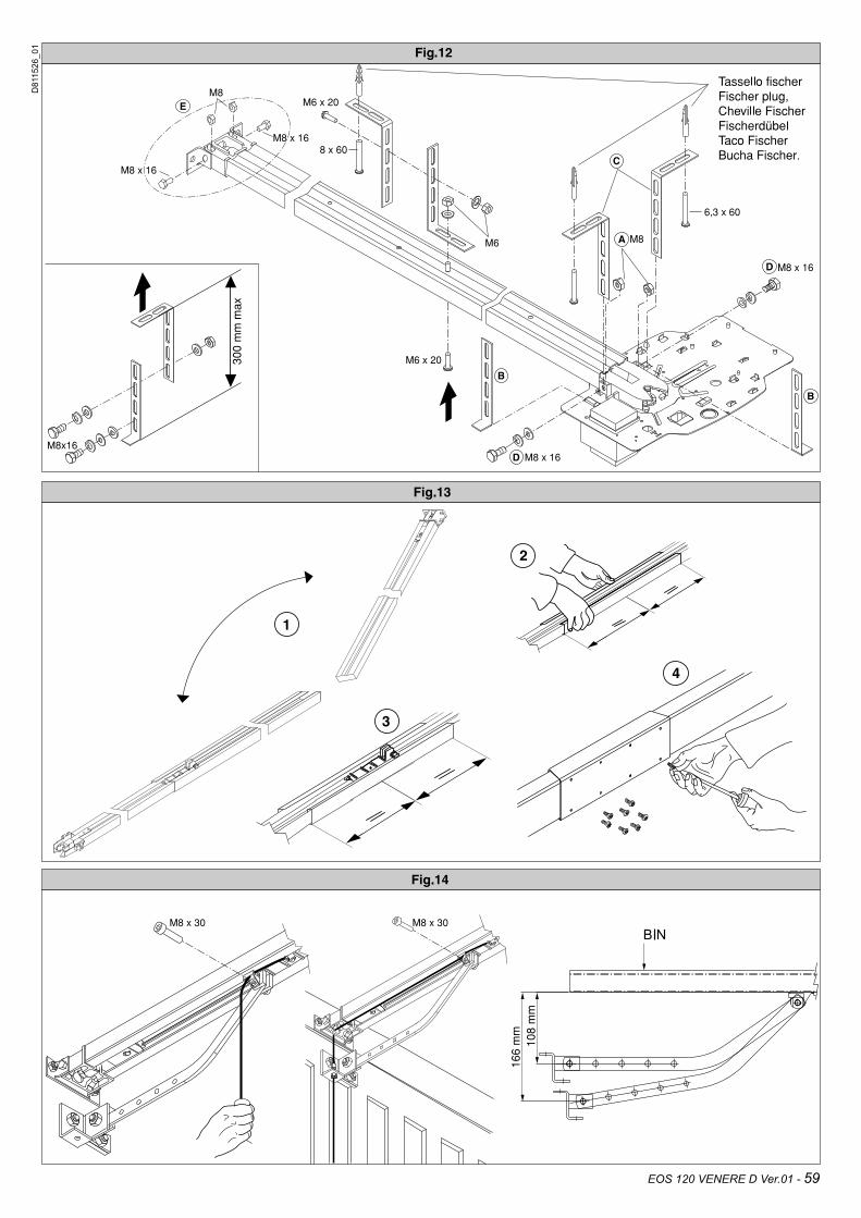
8) In the case where the track is turned by 90° with respect to the motor head, use the reference template in Fig. 11A to cut out the guard, keeping to the measurements indicated. For fixingFor fixing the BIN to the ceiling, see Fig.6 and in case the track is not fixed directly to the ceiling, see Fig.12.
9) In the case where the track is made in two halves, see Fig.13; for the different types of fixing methods, see the previous fig-ures.
10) Release the carriage and fix the anchoring brackets to the doorRelease the carriage and fix the anchoring brackets to the door panel (Fig.14). The distance allowed between track and sec-tional door is 108 to 166 mm. In case of greater distance, it is necessary to use the brackets and lower the motor; in case of shorter distance, it is necessary to shorten the towing plate.
11) Stick the adhesive labels supplied next to the dangerous points (Fig. 5).
5) CHAIN TIGHTENER ADJUSTMENT (EOS 120)The operator supplied is already calibrated and inspected. Should the chain tension need to be adjusted, proceed as shown in fig. 15.WARNING: the anti-tear spring must never be completely com-pressed. Scrupulously check that the spring is not subject to total compression during operation.
6) ELECTRICAL INSTALLATION SET-UP (Fig.16)M) ActuatorFt) Transmitter photocellFr) Receiver photocellsT) 1-2-4 channel transmitter.
Arrange for the connections of accessories and safety and control devices to reach the motor unit, keeping the mains voltage connec-tions clearly separate from the extra low safety voltage connections (24V) by means of the appropriate cable holder (fig. 8 ref. 5P1).Proceed to connection following the indications given in the wiring diagram. The cables for connecting the accessories must be protected by a raceway (fig. 8 ref. 5C1).
7) VENERE D Control panel (Fig.17)Supply to accessories: ....................................24V~ (180mA max)~ (180mA max) (180mA max)...............................................................24V~ Vsafe (180mA max)~ Vsafe (180mA max) Vsafe (180mA max)Torque limiter setting:.................................on closing and openingAutomatic closing time:.............................................from 1 to 180sBlinker connection:.................................................24V~ max 25W~ max 25W max 25WService light switching-on time:.................................................90sIncorporated rolling-code radio receiver:.....frequency 433.92 MHzCoding:..........................................................rolling-code algorithmNo. combinations:..............................................................4 milliardAntenna impedance:...............................................50Ohm (RG58)Max no. radio controls to be memorised:.....................................63Slow-down distance:........closing: ~24 cm............opening: ~24 cmFuses:.........................................................................see figure 17
7.1) Terminal board connections (Fig.17)WARNINGS - For wiring and installation operations, refer to the current standards and good technical principles. The wires supplied with extra low safety voltage (24V) must be kept physically separate from the low voltage wires, or else they must be provided with adequate additional insulation of at least 1mm.The wires must be clamped by an extra fastener near the terminals, for example by bands.
TERMINAL DESCRIPTION
JP2 transformer wiring
JP10 motor wiring
1-2 Antenna input for integrated radio-receiver board(1: BRAID. 2: SIGNAL).
3-4 START input (N.O.)
3-5 STOP input (N.C.) If not used, leave the jumper in-serted.
3-6 PHOTOCELL input (N.C.) If not used, leave the jumper inserted.
3-7 FAULT input (N.O.)Input for photocells provided with checking N.O. contact.
8-9 24 V~ output for blinking light (25 W max).
10-11 24V~ 180mA max output – power supply for pho-tocells or other devices.
12-13 24V~ Vsafe 180mA max output – power supply for checking photocell transmitters.
14-15 Gate-open warning light output (N.O. contact)/2nd radio channel
16-17 PARTIAL OPENING input (N.O.)
8) PROGRAMMINGThe control panel provided with a microprocessor is supplied with function parameters preset by the manufacturer, suitable for stan-dard installations. The preset parameters can be changed by means of the programmer with an incorporated display or by means of a universal palmtop programmer.In the case where programming is carried out by means of a universal palmtop programmer, carefully read the specific instructions for a universal palmtop programmer and proceed as follows. Connect the universal palmtop programmer to the control unit by means of the UNIFLAT accessory. Enter the “CONTROL UNITS” menu, and the “PARAMETERS” submenu, then scroll the display screenfuls using the up/down arrows, and set the numerical values of the parameters listed below.For the function logics, refer to the “LOGIC” submenu.In the case where programming is carried out by means of the incorporated programmer, refer to Fig. A and B and to the “configu-ration” paragraph.
8.1) CONFIGURATIONThe display programmer is used to set all the VENERE D control panel functions.The programmer is provided with three pushbuttons for menu scroll-ing and function parameter configurations (Fig. 2): UP Menu scrolling/value increment key With programming deactivated, the key works as OPEN. DOWN Menu scrolling/value reduction key With programming deactivated, the key works as CLOSE.OK Enter (confirm) keyThe simultaneous pressure of the UP and DOWN keys is used to exit the active menu and move to the preceding menu. If the UP and DOWN keys are pressed simultaneously at the main menu level (parameters, logics, radio, language, default, autosetting, end-of-stroke adjustment), programming is exited and the display is), programming is exited and the display is switched off (the END message is displayed).
18 - EOS 120 VENERE D Ver.01
D811526_01
INSTALLATION MANUAL ENGLISH
The modifications made are only set if the OK key is subsequently pressed.When the OK key is pressed for the first time, the programming mode is entered. The following pieces of information appear on the display at first:- Display Software version- Control unit Software version- Number of total manoeuvres carried out (the value is expressed
in thousands, therefore the display constantly shows 0000 during the first thousand manoeuvres)
- Number of manoeuvres carried out since the latest maintenance operation (the value is expressed in thousands, therefore the display constantly shows 0000 during the first thousand manoeuvres).
- Number of memorised radio control devices.When the OK key is pressed during the initial presentation phase, the first menu (parameters, logics, radio, language, default, autosetting, end-of-stroke adjustment) can be accessed directly.) can be accessed directly.Here follows a list of the main menus and the respective submenus available.The predefined parameter is shown between square brackets [ 0 ].The writing appearing on the display is indicated between round brackets.Refer to Figures A and B for the control unit configuration proce-dure.
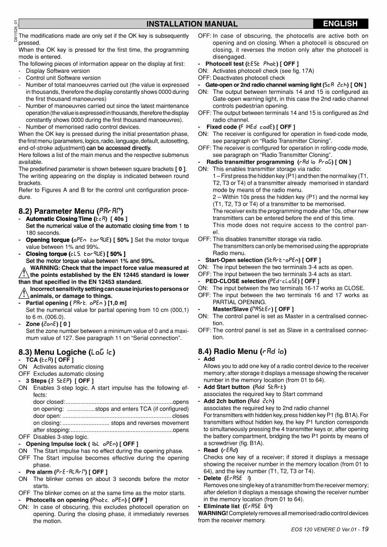
8.2) Parameter Menu ( )- Automatic Closing Time (Automatic Closing Time ( ( ) [ 40s ] Set the numerical value of the automatic closing time from 1 toSet the numerical value of the automatic closing time from 1 to
180 seconds. - Opening torque (Opening torque ( ) [ 50% ] Set the motor torque
value between 1% and 99%. - Closing torque (Closing torque ( ) [ 50% ] [ 50% ] Set the motor torque value between 1% and 99%.Set the motor torque value between 1% and 99%.
WARNING: Check that the impact force value measured at the points established by the EN 12445 standard is lower
than that specified in the EN 12453 standard.Incorrect sensitivity setting can cause injuries to persons or animals, or damage to things.
- Partial opening ( ) [1,0 m] Set the numerical value for partial opening from 10 cm (000,1)
to 6 m. (006.0).- Zone ( ) [ 0 ] Set the zone number between a minimum value of 0 and a maxi-
mum value of 127. See paragraph 11 on “Serial connection”.
8.3) Menu Logiche ( )- TCA ( ) [ OFF ]ON Activates automatic closingOFF Excludes automatic closing- 3 Steps ( ) [ OFF ] ON Enables 3-step logic. A start impulse has the following ef-
fects: door closed: ..................................................................opens on opening: .................stops and enters TCA (if configured) door open: ................................................................... closes on closing: ............................. stops and reverses movement after stopping: ...............................................................opensOFF Disables 3-step logic.- Opening Impulse lock ( ) [ OFF ] ON The Start impulse has no effect during the opening phase.OFF The Start impulse becomes effective during the opening
phase. - Pre alarm ( ) [ OFF ] ON The blinker comes on about 3 seconds before the motor
starts.OFF The blinker comes on at the same time as the motor starts.- Photocells on opening ( ) [ OFF ] ON: In case of obscuring, this excludes photocell operation on
opening. During the closing phase, it immediately reverses the motion.
OFF: In case of obscuring, the photocells are active both on opening and on closing. When a photocell is obscured on closing, it reverses the motion only after the photocell is disengaged.
- Photocell test ( ) [ OFF ] ON: Activates photocell check (see fig. 17A)OFF: Deactivates photocell check- Gate-open or 2nd radio channel warning light ( ) [ ON ]ON: The output between terminals 14 and 15 is configured as
Gate-open warning light, in this case the 2nd radio channel controls pedestrian opening.
OFF: The output between terminals 14 and 15 is configured as 2nd radio channel.
- Fixed code ( ) [ OFF ]ON: The receiver is configured for operation in fixed-code mode,
see paragraph on “Radio Transmitter Cloning”.OFF: The receiver is configured for operation in rolling-code mode,
see paragraph on “Radio Transmitter Cloning”.- Radio transmitter programming ( ) [ ON ]ON: This enables transmitter storage via radio: 1 – First press the hidden key (P1) and then the normal key (T1,
T2, T3 or T4) of a transmitter already memorised in standard mode by means of the radio menu.
2 – Within 10s press the hidden key (P1) and the normal key (T1, T2, T3 or T4) of a transmitter to be memorised.
The receiver exits the programming mode after 10s, other new transmitters can be entered before the end of this time.
This mode does not require access to the control pan-el.
OFF: This disables transmitter storage via radio. The transmitters can only be memorised using the appropriate
Radio menu.- Start-Open selection ( ) [ OFF ]ON: The input between the two terminals 3-4 acts as open.OFF: The input between the two terminals 3-4 acts as start.- PED-CLOSE selection ( ) [ OFF ]ON: The input between the two terminals 16-17 works as CLOSE.OFF: The input between the two terminals 16 and 17 works as
PARTIAL OPENING.- Master/Slave ( ) [ OFF ]ON: The control panel is set as Master in a centralised connec-
tion. OFF: The control panel is set as Slave in a centralised connec-
tion.
8.4) Radio Menu ( ) - Add Allows you to add one key of a radio control device to the receiver
memory; after storage it displays a message showing the receiver number in the memory location (from 01 to 64).
- Add Start button ( ) associates the required key to Start command- Add 2ch button ( ) associates the required key to 2nd radio channel For transmitters with hidden key, press hidden key P1 (fig. B1A). For
transmitters without hidden key, the key P1 function corresponds to simultaneously pressing the 4 transmitter keys or, after opening the battery compartment, bridging the two P1 points by means of a screwdriver (fig. B1A).
- Read ( ) Checks one key of a receiver; if stored it displays a message
showing the receiver number in the memory location (from 01 to 64), and the key number (T1, T2, T3 or T4).
- Delete ( ) Removes one single key of a transmitter from the receiver memory;
after deletion it displays a message showing the receiver number in the memory location (from 01 to 64).
- Eliminate list ( )WARNING! Completely removes all memorised radio control devices from the receiver memory.
EOS 120 VENERE D Ver.01 - 19
D811526_01

8.5) Language Menu ( )Allows you to set the language on the display programmer.5 languages are available:- ITALIAN ( ) - FRENCH ( ) - GERMAN ( )- ENGLISH ( ) - SPANISH ( )
8.6) MENU DEFAULT ( )Restores the preset default values on the control unit. After restoring, a new autoset operation must be carried out.
8.7) DIAGNOSTICS AND MONITORINGThe display on the VENERE D panel shows some useful information, both during normal operation and in the case of malfunctions.
Diagnostics:In the case of malfunctions, the display shows a message indicating which device needs to be checked:STRT = START input activationSTOP = STOP input activationPHOT = PHOT input activationFLT = FAULT input activation for checked photocells SWO = input activation OPENING LIMIT SWITCHSWC = input activation CLOSING LIMIT SWITCHPED = input activation PEDESTRIANOPEN = OPEN input activationCLS = CLOSE input activationIn the case where an obstacle is found, the VENERE D panel stops the door and activates a reverse manoeuvre; at the same time the display shows the “BAR” message.Monitoring:During the opening and closing phases, the display shows four digits separated by a dot, for example Figures are constantly updated during the manoeuvre and represent the instant torque reached by motor 1 ( ) and threshold torque (opening, closing, slow-down) set in the parameter menu ( ). These values allow the torque setting to be corrected.If the istant torque value reached during the manoeuvres turns out to be considerably close to the threshold value set in the parameter menu, future operation failures are likely to occur due to wearing or small door deformations.It is therefore advisable to check the maximum torque reached dur-ing some of the manoeuvres carried out in the course of installation, and if necessary set a value about 5-10 percent points higher in the parameter menu.
8.8) AUTOSET MENU ( )• Bring the door to its closing position.• Initiate an autoset operation by moving to the appropriate VENERE
D panel menu (Fig.B).• As soon as the OK button is pressed, the following message will
be displayed “.... .... ....”, and the control unit initiates an opening manoeuvre followed by a closing manoeuvre, during which the minimum torque value needed for door movement will be auto-matically set.
During this phase, it is important to avoid obscuring the photocells, as well as using the START and STOP commands and the display.
• By the end of this operation, the control unit will have automatically set the optimum torque values. Check and, if necessary, modify them as described in the programming section.
WARNING: Check that the impact force value measured at the points established by the EN 12445 standard is lower
than that specified in the EN 12453 standard.WARNING! During the autoset phase, the obstacle detection function is not optimised; the installer must check the ope-
rator movement and prevent persons and things from coming near or stopping within the operating range.
8.9) LIMIT-SWITCH ADJUSTMENT MENUThe VENERE D control panel is provided with an adjustment menu for opening and closing limit switches, which simplify the installation procedure.
Making reference to Fig. 18 and 19, and Fig. B showing control panel programming, proceed as follows:• Initiate a limit-switch adjustment operation by moving to the
appropriate VENERE D panel menu (Fig.B).• When the “CLOSE” message is displayed, bring the door to the
required closing position using the “UP” and “DOWN” control unit buttons, keeping in mind that the “DOWN” button closes the door whereas the “UP” button opens the door. As soon as the door is in the required closing position, press the “OK” button in order to memorise the closing limit-switch position.
• When the “OPEN” message is displayed, bring the leaf to the desired opening position using the “UP” and “DOWN” buttons on the control unit, keeping in mind that the “DOWN” button closes the leaf whereas the “UP” button opens the leaf. As soon as the door is in the required opening position, press the “OK” button in order to memorise the opening limit-switch position.
• Correctly position the “carriage lock” and use the screws to fix it behind the carriage (fig.18 ref.6 A-B).
NOTA: Ces manoeuvres sont effectuées dans la modalité “a action maintenue”, à vitesse réduite et sans l’intervention des dispositifs de sécurité.
8.10) STATISTICSAfter connecting the UNIVERSAL PALMTOP programmer to the control unit, enter the CONTROL UNIT / STATISTICS menu and scroll the screenful showing the statistical parameters:- Board microprocessor software version.- Number of cycles carried out. If motors are replaced, count the
number of manoeuvres carried out up to that time. - Number of cycles carried out from the latest maintenance opera-
tion. It is automatically set to zero after each self-diagnosis or parameter
writing. - Date of latest maintenance operation. To be updated manually
from the appropriate menu “Update maintenance date”.- Installation description. 16 characters can be entered for instal-
lation identification.
9) INTEGRATED RECEIVER TECHNICAL SPECI-FICATIONReceiver output channels: - output channel 1, if activated, controls a START command. - output channel 2, if activated, controls the excitation of the 2nd
radio channel relay for 1s.Transmitter versions which can be used:all Rolling Code transmitters compatible with .
9.1) ANTENNA INSTALLATIONUse an antenna tuned to 433MHz.For Antenna-Receiver connection, use RG8 coaxial cable.The presence of metallic masses next to the antenna can interfere with radio reception. In case of insufficient transmitter range, move the antenna to a more suitable position.
9.2) RECEIVER CONFIGURATIONCloning operations can be carried out with the special (UNI-RADIO) programmer only. The on-board receiver combines char-acteristics of utmost safety in copying variable code (rolling code) coding with the convenience of carrying out transmitter “cloning” operations thanks to an exclusive system.Cloning a transmitter means creating a transmitter which can be automatically included within the list of the transmitters memorised in the receiver, either as an addition or as a replacement of a par-ticular transmitter.
INSTALLATION MANUALENGLISH
20 - EOS 120 VENERE D Ver.01
D811526_01
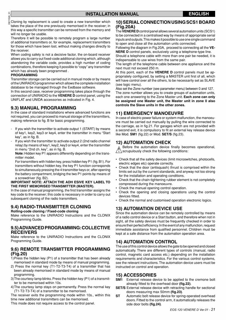
Cloning by replacement is used to create a new transmitter which takes the place of the one previously memorised in the receiver; in this way a specific transmitter can be removed from the memory and will no longer be usable.Therefore it will be possible to remotely program a large number of additional transmitters or, for example, replacement transmitters for those which have been lost, without making changes directly to the receiver. When coding safety is not a decisive factor, the on-board receiver allows you to carry out fixed-code additional cloning which, although abandoning the variable code, provides a high number of coding combinations, therefore keeping it possible to “copy” any transmitter which has already been programmed .PROGRAMMINGTransmitter storage can be carried out in manual mode or by means of the UNIRADIO programmer which allows the complete installation database to be managed through the Eedbase software.In this second case, receiver programming takes place through the connection of UNIRADIO to the VENERE D control panel, using the UNIFLAT and UNIDA accessories as indicated in Fig. 4.
9.3) MANUAL PROGRAMMINGIn the case of standard installations where advanced functions are not required, you can proceed to manual storage of the transmitters, making reference to fig. B for basic programming.
- If you wish the transmitter to activate output 1 (START) by means of key1, key2, key3 or key4, enter the transmitter in menu “Start key”, as in fig. B.
- If you wish the transmitter to activate output 2 (2nd radio channel relay) by means of key1, key2, key3 or key4, enter the transmitter in menu “2nd ch. key”, as in fig. B.
Note: Hidden key P1 appears differently depending on the trans-mitter model.
For transmitters with hidden key, press hidden key P1 (fig. B1). For transmitters without hidden key, the key P1 function corresponds to simultaneously pressing the 4 transmitter keys or, after opening the battery compartment, bridging the two P1 points by means of a screwdriver (fig. B2).
IMPORTANT NOTE: ATTACH THE ADH ESIVE KEY LABEL TO THE FIRST MEMORISED TRANSMITTER (MASTER). In the case of manual programming, the first transmitter assigns the key code to the receiver; this code is necessary in order to carry out subsequent cloning of the radio transmitters.
9.4) RADIO-TRANSMITTER CLONINGRolling-code cloning / Fixed-code cloningMake reference to the UNIRADIO Instructions and the CLONIX Programming Guide.
9.5) ADVANCED PROGRAMMING: COLLECTIVE RECEIVERSMake reference to the UNIRADIO Instructions and the CLONIX Programming Guide.
9.6) REMOTE TRANSMITTER PROGRAMMING (Fig.20)1) Press the hidden key (P1) of a transmitter that has been already
memorised in standard mode by means of manual programming.2) Press the normal key (T1-T2-T3-T4) of a transmitter that has
been already memorised in standard mode by means of manual programming.
3) The courtesy lamp blinks. Press the hidden key (P1) of a transmit-ter to be memorised within 10s.
4) The courtesy lamp stays on permanently. Press the normal key (T1-T2-T3-T4) of a transmitter to be memorised.
The receiver exits the programming mode within 10s., within this time new additional transmitters can be memorised.This mode does not require access to the control panel.
INSTALLATION MANUAL ENGLISH
10) SERIAL CONNECTION USING SCS1 BOARD (Fig.20A) The VENERE D control panel allows several automation units (SCS1) to be connected in a centralised way by means of appropriate serial inputs and outputs. This makes it possible to use one single command to open and close all the automation units connected.Following the diagram in Fig.20A, proceed to connecting all the VE-NERE D control panels, exclusively using a telephone-type line. Should a telephone cable with more than one pair be needed, it is indispensable to use wires from the same pair.The length of the telephone cable between one appliance and the next must not exceed 250 m.At this point, each of the VENERE D control panels must be ap-propriately configured, by setting a MASTER unit first of all, which will have control over all the others, to be necessarily set as SLAVE (see logic menu).Also set the Zone number (see parameter menu) between 0 and 127. The zone number allows you to create groups of automation units, each one answering to the Zone Master unit. Each zone can only be assigned one Master unit, the Master unit in zone 0 also controls the Slave units in the other zones.
11) EMERGENCY MANOEUVREIn case of electric power failure or system malfunction, the manoeu-vre must be carried out manually by pulling the wire connected to the carriage, as in fig.21. For garages which are not provided with a second exit, it is compulsory to fit an external key release device like Mod. SM1 (fig.22) or Mod. SET/S (fig.23).
12) AUTOMATION CHECK Before the automation device finally becomes operational, scrupulously check the following conditions:
• Check that all the safety devices (limit microswitches, photocells, electric edges etc) operate correctly.
• Check that the door (antisquash) thrust is comprised within the limits set out by the current standards, and anyway not too strong for the installation and operating conditions.
• Check that the chain-tightening rubber element is not completely compressed during the manoeuvre.
• Check the manual opening control operation.• Check the opening and closing operations using the control
devices fitted.• Check the normal and customised operation electronic logics.
13) AUTOMATION DEVICE USESince the automation device can be remotely controlled by means of a radio control device or a Start button, and therefore when not in sight, all the safety devices must be frequently checked in order to ensure their perfect efficiency. In the event of any malfunction, request immediate assistance from qualified personnel. Children must be kept at a safe distance from the automation operation area.
14) AUTOMATION CONTROLThe use of this control device allows the gate to be opened and closed automatically. There are different types of controls (manual, radio control, magnetic card access etc.) depending on the installation requirements and characteristics. For the various control systems, see the relevant instructions. The automation device users must be instructed on control and operation.
15) ACCESSORIESSM1 External release device to be applied to the cremone bolt
already fitted to the overhead door (fig.22).SET/S External release device with retracting handle for sectional
doors measuring max 50mm (fig.23).ST Automatic bolt release device for spring-operated overhead
doors. Fitted to the control arm, it automatically releases the side door bolts (fig.24).
EOS 120 VENERE D Ver.01 - 21
D811526_01
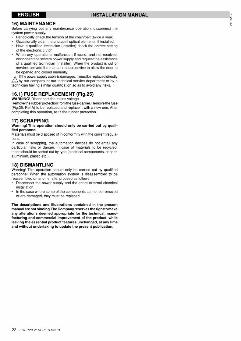
16) MAINTENANCEBefore carrying out any maintenance operation, disconnect the system power supply.• Periodically check the tension of the chain/belt (twice a year).• Occasionally clean the photocell optical elements, if installed.• Have a qualified technician (installer) check the correct setting
of the electronic clutch.• When any operational malfunction if found, and not resolved,
disconnect the system power supply and request the assistance of a qualified technician (installer). When the product is out of service, activate the manual release device to allow the door to be opened and closed manually.
If the power supply cable is damaged, it must be replaced directly by our company or our technical service department or by a
technician having similar qualification so as to avoid any risks.
16.1) FUSE REPLACEMENT (Fig.25)WARNING! Disconnect the mains voltage. Remove the rubber protection from the fuse-carrier. Remove the fuse (Fig.25, Ref.A) to be replaced and replace it with a new one. After completing this operation, re-fit the rubber protection. 17) SCRAPPINGWarning! This operation should only be carried out by quali-fied personnel.Materials must be disposed of in conformity with the current regula-tions.In case of scrapping, the automation devices do not entail any particular risks or danger. In case of materials to be recycled, these should be sorted out by type (electrical components, copper, aluminium, plastic etc.).
18) DISMANTLINGWarning! This operation should only be carried out by qualified personnel. When the automation system is disassembled to be reassembled on another site, proceed as follows:• Disconnect the power supply and the entire external electrical
installation.• In the case where some of the components cannot be removed
or are damaged, they must be replaced.
The descriptions and illustrations contained in the present manual are not binding. The Company reserves the right to make any alterations deemed appropriate for the technical, manu-facturing and commercial improvement of the product, while leaving the essential product features unchanged, at any time and without undertaking to update the present publication.
INSTALLATION MANUALENGLISH
22 - EOS 120 VENERE D Ver.01
D811526_01

LEGENDA
Fig. A
OK
Press the OK key
[ ]
Parameter increment/reductionor ON/OFF commutation
Menu scrolling(+ = preceding - = following)
Press OK key (Enter/confirm)
OK! message (confirms modification made)
OK
OK
+ -
+ -
+ -
OK
ACCESS TO MENUS
FOLLOWING MENUSFIG. B
- +
/ON/OFF
- +
- +
Control unit software version
No. total manoeuvres (in thousands)
No. manoeuvres since latest maintenance(in thousands)
No. radio control devices memorised
KO! message (value or function error)
“Wait” message (enter value or function)
+ -
Simultaneously press the + and - keys.Simultaneous pressure of the + and – keys allows you to exit the active menu and return to the preceding menu; if this takes place at the main menu level, programming is exited and the display switched off.The modifications made are only confirmed if the OK key is subsequently pressed.
Preset value
+ -
OK
OK
EOS 120 VENERE D Ver.01 - 23
D811526_01

Fig. B
PRECEDING MENUSFIG. A
T1
T2
T1
T2
T3
T4
1 2 3
T1 T2 T1 T2
T3 T4
P1P1
P1
- +
- +
+ -
OK
+ -
Press P1 (pushbutton) on radio control device.
Press the required T (key) on radio control device – see Fig. B3
Press the required T (key) on radio control device – see Fig. B3
Release P1 on radio control device
OK
OK
OK
- +
- +
Press P1 (pushbutton) on radio control device.
Press the required T (key) on radio control device – see Fig. B3
Release P1 on radio control device
OK
- +
OK OK OK OK
- + + -
24 - EOS 120 VENERE D Ver.01
D811526_01
146
253.16
65
378
35
3380-2780
3760-3160
1
2
250
E14 24V
25W max
EOS 120 VENERE D Ver.01 - 57
D811526_01

58 - EOS 120 VENERE D Ver.01
D811526_01
EOS 120 VENERE D Ver.01 - 59
D811526_01

60 - EOS 120 VENERE D Ver.01
D811526_01

EOS 120 VENERE D Ver.01 - 61
D811526_01

62 - EOS 120 VENERE D Ver.01
D811526_01

EOS 120 VENERE D Ver.01 - 63
D811526_01