p ¸?}b )*( (mm) - jsce 公益社団法人 土木学会 · pdf file ·...
TRANSCRIPT

Analysis of Concrete Cover Spalling due to Rebar Corrosion
D. Qiao, T. Nakano and H. Nakamura
Department of Civil Engineering, Nagoya University, Japan
Abstract: This study examined the applicability of previously proposed corrosion expansion model on the base of rigid
body spring method to model the concrete cover spalling, which is a part of research aiming at clarifying the mechanism
of corrosion-induced cover spalling. It is also found that localized corrosion can result in the internal cracks developing
diagonally to concrete surface and then a sudden spalling, which poses a remarkable threat to the safety of structure.
1. Introduction
The serviceability of ageing reinforced concrete
structures is greatly affected by internal rebar corrosion as
corrosion products of rebar occupy larger volume than
original rebar, impose expansion pressure on surrounding
concrete, and then induce concrete cover cracking and
spalling. Although there are a number of researches
focusing on cracking mechanism of the corroded
structures, few of them are extended to cover spalling.
However, it cannot be ignored since it’s strongly related
with the safety of structures in terms of the influences on
human’s safety.
The study currently conducted try to identify the
influence factors of corrosion-induced cover spalling,
specifically to clarify the relationship between localized
corrosion and cover spalling. Here, the applicability of
analytical method, which was based on Rigid Body
Spring Method with corrosion expansion model, was
verified by comparison with experimental results.
2. Outline of Analysis
2.1 Specimen
Three rebars were embedded into the concrete specimen
with a compressive strength of 40MPa during experiment.
The specimen dimension is shown in Fig.1. Part of the
bottom of concrete specimen, which is marked in red in
Fig.1, was in touch with salty water by the link of sponge
in order to reach the state of localized corrosion. A DC
power was used to carry out accelerated corrosion process
and conduction time was determined based on Faraday’s
law. Three objective corrosion degree varying as 5%,
10% and 15% were studied in the test. After artificial
corrosion process, the surface cracking map was
monitored and then the specimen was cut in different
positions, where the internal crack pattern was
investigated. Fig.2 shows the distribution of corrosion
degree along rebar. It can be seen that it is distributed in
the shape of triangle and the part that was connected with
sponge exhibits a higher corrosion rate.
For simulation, RBSM model corresponding to this
specimen was established using Voronoi random
polygons. It is noted that only one rebar was introduced
into the model because the other two rebars were barely
corroded and it can also reduce the computation burden.
2.2 Corrosion Expansion Model
In previous study of our lab (Tran et al. (2011)),
expansion of corrosion products inside concrete due to
rebar corrosion was modeled by internal expansion
pressure, which was simulated with increment of initial
strain applied on the boundary between rust layer and
rebar layer as determined by Eq. (1).
corcor r 0 r
U UE E
H H
(1)
Where Er is elasticity modulus of corrosion product,
Ucor increment of real increase of rebar radius confined
by surrounding concrete, U free increase of rebar radius
and H thickness of corrosion product layer. In addition, it
was reported in the work of Yuan and Ji (2009) that the
corrosion products distribute on the half circumference of
rebar facing concrete cover. Hence, during simulation
increment of initial strain was only applied over one-
quarter of the model, which was also based on the
distribution of corrosion degree as shown in Fig 2.
This model combined with RBSM method is
appropriate to evaluate corrosion-induced cracking
behavior of concrete cover and agrees well with
accelerated corrosion test result (Tran et al. (2011)).
a) Section b) Side view
Fig. 1 Specimen dimensions
Fig. 2 Distribution of corrosion degree
3. Result and Discussion
It is observed that cover spalling occurs when practical
corrosion degree reaches 12.5% at the center part for this
specimen size. The comparisons between simulation and
experimental results presented here account for two kinds
of corrosion degree, a small corrosion degree of 4.84%
and a large corrosion degree of 12.5% to illustrate the
applicability of the numerical model.
600
700
30
150
30
210
105105
30150
210
-30 -20 -10 0 10 20 300
5
10
15
中央からの位置(mm)
腐食率
(%)
-30 -20 -10 0 10 20 300
5
10
15
中央からの位置(cm)
腐食率
(%)
-30 -20 -10 0 10 20 300
5
10
中央からの位置(cm)
腐食率
(%)
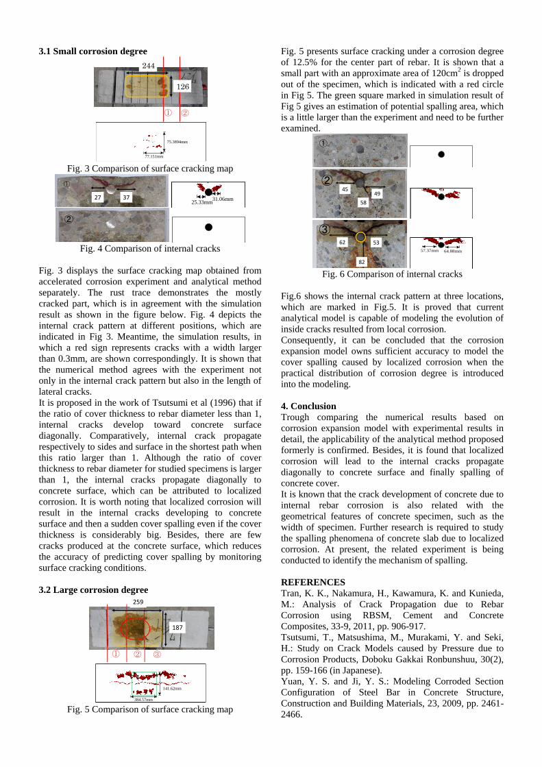
3.1 Small corrosion degree
Fig. 3 Comparison of surface cracking map
Fig. 4 Comparison of internal cracks
Fig. 3 displays the surface cracking map obtained from
accelerated corrosion experiment and analytical method
separately. The rust trace demonstrates the mostly
cracked part, which is in agreement with the simulation
result as shown in the figure below. Fig. 4 depicts the
internal crack pattern at different positions, which are
indicated in Fig 3. Meantime, the simulation results, in
which a red sign represents cracks with a width larger
than 0.3mm, are shown correspondingly. It is shown that
the numerical method agrees with the experiment not
only in the internal crack pattern but also in the length of
lateral cracks.
It is proposed in the work of Tsutsumi et al (1996) that if
the ratio of cover thickness to rebar diameter less than 1,
internal cracks develop toward concrete surface
diagonally. Comparatively, internal crack propagate
respectively to sides and surface in the shortest path when
this ratio larger than 1. Although the ratio of cover
thickness to rebar diameter for studied specimens is larger
than 1, the internal cracks propagate diagonally to
concrete surface, which can be attributed to localized
corrosion. It is worth noting that localized corrosion will
result in the internal cracks developing to concrete
surface and then a sudden cover spalling even if the cover
thickness is considerably big. Besides, there are few
cracks produced at the concrete surface, which reduces
the accuracy of predicting cover spalling by monitoring
surface cracking conditions.
3.2 Large corrosion degree
Fig. 5 Comparison of surface cracking map
Fig. 5 presents surface cracking under a corrosion degree
of 12.5% for the center part of rebar. It is shown that a
small part with an approximate area of 120cm2 is dropped
out of the specimen, which is indicated with a red circle
in Fig 5. The green square marked in simulation result of
Fig 5 gives an estimation of potential spalling area, which
is a little larger than the experiment and need to be further
examined.
Fig. 6 Comparison of internal cracks
Fig.6 shows the internal crack pattern at three locations,
which are marked in Fig.5. It is proved that current
analytical model is capable of modeling the evolution of
inside cracks resulted from local corrosion.
Consequently, it can be concluded that the corrosion
expansion model owns sufficient accuracy to model the
cover spalling caused by localized corrosion when the
practical distribution of corrosion degree is introduced
into the modeling.
4. Conclusion
Trough comparing the numerical results based on
corrosion expansion model with experimental results in
detail, the applicability of the analytical method proposed
formerly is confirmed. Besides, it is found that localized
corrosion will lead to the internal cracks propagate
diagonally to concrete surface and finally spalling of
concrete cover.
It is known that the crack development of concrete due to
internal rebar corrosion is also related with the
geometrical features of concrete specimen, such as the
width of specimen. Further research is required to study
the spalling phenomena of concrete slab due to localized
corrosion. At present, the related experiment is being
conducted to identify the mechanism of spalling.
REFERENCES
Tran, K. K., Nakamura, H., Kawamura, K. and Kunieda,
M.: Analysis of Crack Propagation due to Rebar
Corrosion using RBSM, Cement and Concrete
Composites, 33-9, 2011, pp. 906-917.
Tsutsumi, T., Matsushima, M., Murakami, Y. and Seki,
H.: Study on Crack Models caused by Pressure due to
Corrosion Products, Doboku Gakkai Ronbunshuu, 30(2),
pp. 159-166 (in Japanese).
Yuan, Y. S. and Ji, Y. S.: Modeling Corroded Section
Configuration of Steel Bar in Concrete Structure,
Construction and Building Materials, 23, 2009, pp. 2461-
2466.
① ②
244
126
77.151mm
75.3894mm
3727
①
25.33mm31.06mm
②
187
259
① ② ③
384.57mm
141.62mm
①
49
58
45②
62 53
82
③
64.88mm57.37mm