p din instruction manual
TRANSCRIPT

8/20/2019 P DIn Instruction Manual
http://slidepdf.com/reader/full/p-din-instruction-manual 1/52
Process Add-On Instructions and Graphics:
Discrete Input (P_DIn)
Reference Manual
Compatible with the Plant-wide Integrated Architecture™
8/20/2019 P DIn Instruction Manual
http://slidepdf.com/reader/full/p-din-instruction-manual 2/52
Important User Information
Solid state equipment has operational characteristics differing from those of electromechanical equipment. Safety Guidelines for the Application, Installation and Maintenance of Solid State Controls (publication SGI-1.1 available from your local Rockwell Automation sales officeor online at http://rockwellautomation.com/literature ) describes some important differences between solid state equipment and hard-wired
electromechanical devices. Because of this difference, and also because of the wide variety of uses for solid state equipment, all persons responsible for applying this equipment must satisfy themselves that each intended application of this equipment is acceptable.
In no event will Rockwell Automation, Inc. be responsible or liable for indirect or consequential damages resulting from the use or applicationof this equipment.
The examples and diagrams in this manual are included solely for illustrative purposes. Because of the many variables and requirements as-sociated with any particular installation, Rockwell Automation, Inc. cannot assume responsibility or liability for actual use based on the ex-
amples and diagrams.
No patent liability is assumed by Rockwell Automation, Inc. with respect to use of information, circuits, equipment, or software described inthis manual.
Reproduction of the contents of this manual, in whole or in part, without written permission of Rockwell Automation, Inc., is prohibited.
Throughout this manual, when necessary, we use notes to make you aware of safety considerations.
Allen-Bradley, Rockwell Automation, and TechConnect are trademarks of Rockwell Automation, Inc.
Trademarks not belonging to Rockwell Automation, Plant PAx Process Automation System, and TechConnect are property of their respective companies.
WARNING
Identifies information about practices or circumstances that can cause an explosion in a
hazardous environment, which may lead to personal injury or death, property damage, oreconomic loss.
IMPORTANT Identifies information that is critical for successful application and understanding of the product.
ATTENTIONIdentifies information about practices or circumstances that can lead to personal injury or death,
property damage, or economic loss. Attentions help you identify a hazard, avoid a hazard, and
recognize the consequence.
SHOCK HAZARD Labels may be on or inside the equipment, for example, a drive or motor, to alert people that
dangerous voltage may be present.
BURN HAZARD Labels may be on or inside the equipment, for example, a drive or motor, to alert people that
surfaces may reach dangerous temperatures.

8/20/2019 P DIn Instruction Manual
http://slidepdf.com/reader/full/p-din-instruction-manual 3/52
iiiPublication SYSLIB-RM003C-EN-E - October 2011 iii
Summary of Changes
Introduction This release of this document is updated throughout for version 2.0 of theDiscrete Input (P_DIn) Add-On Instruction and Graphics. Please refer to theRelease Notes that are distributed with version 2.0 of the Library.
Updated Information This document contains the following changes:
Change: See:
Version 2.0 of instruction All

8/20/2019 P DIn Instruction Manual
http://slidepdf.com/reader/full/p-din-instruction-manual 4/52
iv Publication SYSLIB-RM003C-EN-E - October 2011
Summary of Changes
Notes:
8/20/2019 P DIn Instruction Manual
http://slidepdf.com/reader/full/p-din-instruction-manual 5/52
vPublication SYSLIB-RM003C-EN-E - October 2011 v
Table of Contents
Preface Use of this Document . . . . . . . . . . . . . . . . . . . . . . . . . . . . . . . . . . . . . . vii
Conventions and Related Terms . . . . . . . . . . . . . . . . . . . . . . . . . . . . . . vii
Set and Clear . . . . . . . . . . . . . . . . . . . . . . . . . . . . . . . . . . . . . . . . . . vii
Edge and Level. . . . . . . . . . . . . . . . . . . . . . . . . . . . . . . . . . . . . . . . viii
Relay Ladder Rung Condition. . . . . . . . . . . . . . . . . . . . . . . . . . . . . ix
Pre-Scan . . . . . . . . . . . . . . . . . . . . . . . . . . . . . . . . . . . . . . . . . . . . . . . x
Function Block States . . . . . . . . . . . . . . . . . . . . . . . . . . . . . . . . . . . . x
Entering Text in FactoryTalk View SE. . . . . . . . . . . . . . . . . . . . . . xi
Chapter 1
Overview Functional Description . . . . . . . . . . . . . . . . . . . . . . . . . . . . . . . . . . . . . . 2
Primary Operations . . . . . . . . . . . . . . . . . . . . . . . . . . . . . . . . . . . . . . . . . 3
Operating Modes . . . . . . . . . . . . . . . . . . . . . . . . . . . . . . . . . . . . . . . . . . . 3
Alarms. . . . . . . . . . . . . . . . . . . . . . . . . . . . . . . . . . . . . . . . . . . . . . . . . . . . 4
Execution . . . . . . . . . . . . . . . . . . . . . . . . . . . . . . . . . . . . . . . . . . . . . . . . . 4
Implementation Using the EnableIn FALSE Feature . . . . . . . . . . . . . . 5
Revision Compatibility. . . . . . . . . . . . . . . . . . . . . . . . . . . . . . . . . . . . . . . 6
Chapter 2
Configuration Options Configuration Parameters . . . . . . . . . . . . . . . . . . . . . . . . . . . . . . . . . . . . 7
Chapter 3
Instruction Data Reference Execution . . . . . . . . . . . . . . . . . . . . . . . . . . . . . . . . . . . . . . . . . . . . . . . . 11
Inputs (Inp_) . . . . . . . . . . . . . . . . . . . . . . . . . . . . . . . . . . . . . . . . . . . . . 12
Configurations (Cfg_) . . . . . . . . . . . . . . . . . . . . . . . . . . . . . . . . . . . . . . 12
Configurations in Local Tags . . . . . . . . . . . . . . . . . . . . . . . . . . . . . 14
Operator Settings, Maintenance Settings, Other Settings
(OSet_, MSet_, Set_) . . . . . . . . . . . . . . . . . . . . . . . . . . . . . . . . . . . . . . . 14
Program Commands (PCmd_) . . . . . . . . . . . . . . . . . . . . . . . . . . . . . . . 15
Alarm Commands . . . . . . . . . . . . . . . . . . . . . . . . . . . . . . . . . . . . . . 15
Operator Commands, Maintenance Commands, Command Readies
(OCmd_, MCmd_, Rdy_) . . . . . . . . . . . . . . . . . . . . . . . . . . . . . . . . . . . 16
Device Commands. . . . . . . . . . . . . . . . . . . . . . . . . . . . . . . . . . . . . . 16
Alarm Commands . . . . . . . . . . . . . . . . . . . . . . . . . . . . . . . . . . . . . . 16
Device Command Readies . . . . . . . . . . . . . . . . . . . . . . . . . . . . . . . 17
Alarm Command Readies . . . . . . . . . . . . . . . . . . . . . . . . . . . . . . . . 18
Values (Val_) . . . . . . . . . . . . . . . . . . . . . . . . . . . . . . . . . . . . . . . . . . . . . 18
Status (Sts_) . . . . . . . . . . . . . . . . . . . . . . . . . . . . . . . . . . . . . . . . . . . . . . 20Device Status . . . . . . . . . . . . . . . . . . . . . . . . . . . . . . . . . . . . . . . . . . 20
Alarm Status . . . . . . . . . . . . . . . . . . . . . . . . . . . . . . . . . . . . . . . . . . . 20

8/20/2019 P DIn Instruction Manual
http://slidepdf.com/reader/full/p-din-instruction-manual 6/52
vi Publication SYSLIB-RM003C-EN-E - October 2011
Table of Contents
Chapter 4
HMI Reference Graphic Symbols . . . . . . . . . . . . . . . . . . . . . . . . . . . . . . . . . . . . . . . . . . 23
Process Variable State Indicator . . . . . . . . . . . . . . . . . . . . . . . . . . . 24
Alarm Indicators . . . . . . . . . . . . . . . . . . . . . . . . . . . . . . . . . . . . . . . 26
Using Graphics Symbols . . . . . . . . . . . . . . . . . . . . . . . . . . . . . . . . . 27Faceplate . . . . . . . . . . . . . . . . . . . . . . . . . . . . . . . . . . . . . . . . . . . . . . . . . 27
Operator Tab . . . . . . . . . . . . . . . . . . . . . . . . . . . . . . . . . . . . . . . . . . 28
Alarms Tab. . . . . . . . . . . . . . . . . . . . . . . . . . . . . . . . . . . . . . . . . . . . 30
Maintenance Tab . . . . . . . . . . . . . . . . . . . . . . . . . . . . . . . . . . . . . . . 32
Engineering Tab. . . . . . . . . . . . . . . . . . . . . . . . . . . . . . . . . . . . . . . . 34
Alarm Configuration Tab . . . . . . . . . . . . . . . . . . . . . . . . . . . . . . . . 36
Discrete Input Faceplate Help . . . . . . . . . . . . . . . . . . . . . . . . . . . . 38

8/20/2019 P DIn Instruction Manual
http://slidepdf.com/reader/full/p-din-instruction-manual 7/52
viiPublication SYSLIB-RM003C-EN-E - October 2011 vii
Preface
Use of this Document This document provides a programmer with details on the P_DIn instructionfor a Logix-based controller. You should already be familiar with how theLogix-based controller stores and processes data.
Novice programmers should read all the details about an instruction beforeusing the instruction. Experienced programmers can refer to the instructioninformation to verify details.
Conventions and RelatedTerms
Set and Clear
This manual uses set and clear to define the status of bits (booleans) and values(non-booleans):
This term: Means:
Set The bit is set to 1 (ON) A value is set to any non-zero number
Clear The bit is cleared to 0 (OFF) All the bits in a value are cleared to 0
8/20/2019 P DIn Instruction Manual
http://slidepdf.com/reader/full/p-din-instruction-manual 8/52
viii Publication SYSLIB-RM003C-EN-E - October 2011
Preface
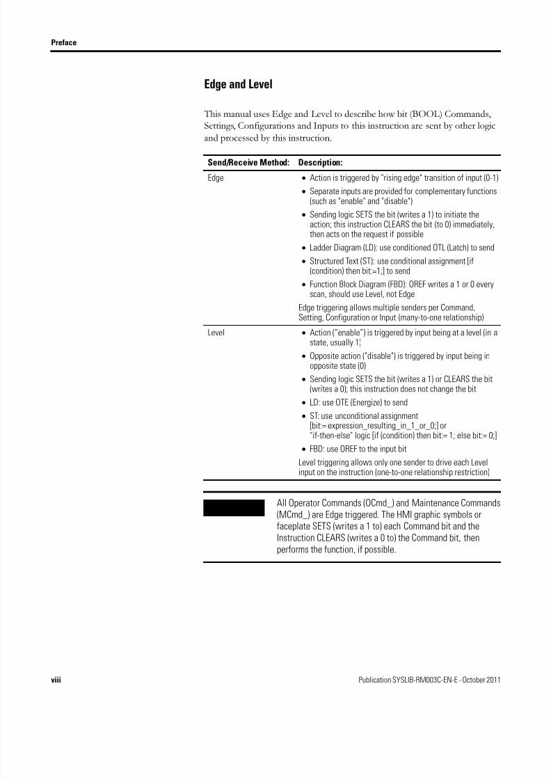
Edge and Level
This manual uses Edge and Level to describe how bit (BOOL) Commands,Settings, Configurations and Inputs to this instruction are sent by other logic
and processed by this instruction.
Send/Receive Method: Description:
Edge • Action is triggered by "rising edge" transition of input (0-1)
• Separate inputs are provided for complementary functions(such as "enable" and "disable")
• Sending logic SETS the bit (writes a 1) to initiate theaction; this instruction CLEARS the bit (to 0) immediately,then acts on the request if possible
• Ladder Diagram (LD): use conditioned OTL (Latch) to send
• Structured Text (ST): use conditional assignment [if
(condition) then bit:=1;] to send• Function Block Diagram (FBD): OREF writes a 1 or 0 every
scan, should use Level, not Edge
Edge triggering allows multiple senders per Command,Setting, Configuration or Input (many-to-one relationship)
Level • Action (“enable”) is triggered by input being at a level (in astate, usually 1)
• Opposite action ("disable") is triggered by input being inopposite state (0)
• Sending logic SETS the bit (writes a 1) or CLEARS the bit(writes a 0); this instruction does not change the bit
• LD: use OTE (Energize) to send
• ST: use unconditional assignment[bit:= expression_resulting_in_1_or_0;] or"if-then-else" logic [if (condition) then bit:= 1; else bit:= 0;]
• FBD: use OREF to the input bit
Level triggering allows only one sender to drive each Levelinput on the instruction (one-to-one relationship restriction)
IMPORTANT All Operator Commands (OCmd_) and Maintenance Commands(MCmd_) are Edge triggered. The HMI graphic symbols orfaceplate SETS (writes a 1 to) each Command bit and theInstruction CLEARS (writes a 0 to) the Command bit, then
performs the function, if possible.

8/20/2019 P DIn Instruction Manual
http://slidepdf.com/reader/full/p-din-instruction-manual 9/52
Publication SYSLIB-RM003C-EN-E - October 2011 ix
Preface
Relay Ladder Rung Condition
The controller evaluates ladder instructions based on the rung conditionpreceding the instruction (rung-in condition). Based on the rung-in condition
and the instruction, the controller sets the rung condition following theinstruction (rung-out condition), which in turn, affects any subsequentinstruction.
If the rung-in condition to an input instruction is true, the controller evaluatesthe instruction and sets the rung-out condition based on the results of theinstruction. If the instruction evaluates to true, the rung-out condition is true;
if the instruction evaluates to false, the rung-out condition is false.
IMPORTANT This instruction has Program Commands (PCmd_) which areselectable as Edge or Level, depending on the ConfigurationParameter Cfg_PCmdClear. If Cfg_PCmdClear is 1 (the default),all Program Commands are CLEARED when received (edge). If
Cfg_PCmdClear is 0, Program Commands as noted in theInstruction Data Reference become Level triggered, andopposite functions are triggered by the primary ProgramCommand being CLEARED to 0.
IMPORTANT The rung-in condition is reflected in the EnableIn parameter anddetermines how the instruction performs each Process Add-OnInstruction. If the EnableIn signal is TRUE, the instructionperforms the instruction’s main logic routine. Conversely, if theEnableIn signal is FALSE, the instruction performs theinstruction’s EnableInFalse routine.
The instruction’s main logic routine sets/clears the EnableOutparameter, which then determines the rung-out condition. TheEnableInFalse routine cannot set the EnableOut parameter. Ifthe rung-in condition is FALSE, then the EnableOut parameterand the rung-out condition will also be FALSE.

8/20/2019 P DIn Instruction Manual
http://slidepdf.com/reader/full/p-din-instruction-manual 10/52
x Publication SYSLIB-RM003C-EN-E - October 2011
Preface
Pre-Scan
On the transition into RUN, the controller performs a pre-scan before the firstlogic scan. pre-scan is a special scan of all routines in the controller. The
controller scans all main routines and subroutines during Pre-Scan, but ignoresjumps that could skip the execution of instructions. The controller executes allFOR loops and subroutine calls. If a subroutine is called more than once, it isexecuted each time it is called. The controller uses Pre-Scan instructions toreset non-retentive data values.
During pre-scan, input values are not current and outputs are not written. Thefollowing conditions generate pre-scan:
• toggle from Program to Run mode.
• automatically enter Run mode from a power-up condition.
pre-scan does not occur for a program when:
• the program becomes scheduled while the controller is running.
• the program is unscheduled when the controller enters Run mode.
Function Block States
The controller evaluates function block instructions based on the state ofdifferent conditions.
IMPORTANT The pre-scan process carries out the Process Add-OnInstruction’s logic routine as FALSE and then carries out itsPre-Scan routine as TRUE.
Possible Condition: Description:
Pre-scan pre-scan for function block routines is the same as for relayladder routines. The only difference is that the Enablelnparameter for each function block instruction is cleared duringpre-scan.
Instruction first scan Instruction first scan refers to the first time an instruction isexecuted after pre-scan. The controller uses instruction firstscan to read current inputs and determine the appropriatestate to be in.
Instruction first run Instruction first run refers to the first time the instructionexecutes with a new instance of a data structure. Thecontroller uses instruction first run to generate coefficientsand other data stores that do not change for a function blockafter initial download.

8/20/2019 P DIn Instruction Manual
http://slidepdf.com/reader/full/p-din-instruction-manual 11/52
Publication SYSLIB-RM003C-EN-E - October 2011 xi
Preface
Every function block instruction also includes EnableIn and EnableOutparameters.
If the EnableIn parameter is not wired, the instruction always executes asnormal and EnableIn remains set. If you clear EnableIn, it changes to set thenext time the instruction executes.
Entering Text in FactoryTalk View SE
When entering data into String Input fields in FactoryTalk View SE, the data isnot saved to the tag until the user presses the Enter key. When the Input Fieldis enabled, its border changes based on the state of the input:
• When the Input Field is Active (the cursor is in the field), the Input Field border is a
solid line.
• If the user modifies the data in the input field and moves to a different field without
pressing the Enter key, the border remains a solid line indicating that the data has not
been saved to the tag.
• If the data in the Input Field has not changed or has been written to the controller
tag, the border is a dashed line.
IMPORTANT When programming in function block, restrict the range
of engineering units to ±10±15 because internal floatingpoint calculations are done using single precision floatingpoint. Engineering units outside of this range may result ina loss of accuracy if results approach the limitations of
single precision floating point (±10±38 ).
EXAMPLE
EXAMPLE
EXAMPLE

8/20/2019 P DIn Instruction Manual
http://slidepdf.com/reader/full/p-din-instruction-manual 12/52
xii Publication SYSLIB-RM003C-EN-E - October 2011
Preface
Notes:

8/20/2019 P DIn Instruction Manual
http://slidepdf.com/reader/full/p-din-instruction-manual 13/52
1Publication SYSLIB-RM003C-EN-E - October 2011 1
Chapter 1
Overview
The Discrete Input Add-On Instruction is used to receive and process a singlediscrete condition (a bit, the Process Variable or PV), typically for a channel ofa discrete input card. It can be used with any discrete (BOOL) signal. TheDiscrete Input Add-On Instruction includes the capability to generate adiscrete input Status, such as from a low level switch, high vibration switch, orflow switch, plus a Target Disagree Status and Alarm.
Use when:
• You want to display the state of a process temperature, level, flow,
proximity, pressure or other switch.• You need any of these signal processing or alarming features for a
Discrete Input or any Discrete (bit) value:
• Debounce of the discrete input signal.
• Target Disagree Status and optional Alarm when the DiscreteInput is not in a Target state for some period of time.
• Target Disagree Status and optional Alarm when a gating conditionis true for some period of time.
• Display of the input state with configurable text on an HMI object with operator faceplate call-up.
• Ability for Maintenance to provide a substitute value when the
device has failed.
Do NOT use when:
• You only need to show or not show the state of a bit on an HMI display.Use basic display objects (text, multi-state indicators) with appropriateanimation instead.
• You only need to generate an alarm from some condition you alreadyhave in your code. Use the P_Alarm Add-On Instruction or the ALMDbuilt-in instruction instead.

8/20/2019 P DIn Instruction Manual
http://slidepdf.com/reader/full/p-din-instruction-manual 14/52
2 Publication SYSLIB-RM003C-EN-E - October 2011
Chapter 1 Overview
Functional Description The functions of the P_DIn Instruction are shown in the following figure:
8/20/2019 P DIn Instruction Manual
http://slidepdf.com/reader/full/p-din-instruction-manual 15/52
Publication SYSLIB-RM003C-EN-E - October 2011 3
Overview Chapter 1
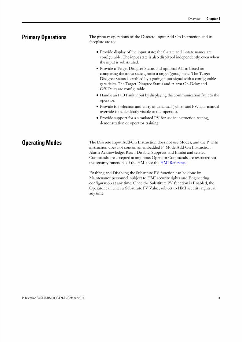
Primary Operations The primary operations of the Discrete Input Add-On Instruction and itsfaceplate are to:
• Provide display of the input state; the 0-state and 1-state names areconfigurable. The input state is also displayed independently, even whenthe input is substituted.
• Provide a Target Disagree Status and optional Alarm based oncomparing the input state against a target (good) state. The TargetDisagree Status is enabled by a gating input signal with a configurablegate delay. The Target Disagree Status and Alarm On-Delay andOff-Delay are configurable.
• Handle an I/O Fault input by displaying the communication fault to theoperator.
• Provide for selection and entry of a manual (substitute) PV. This manualoverride is made clearly visible to the operator.
•Provide support for a simulated PV for use in instruction testing,demonstration or operator training.
Operating Modes The Discrete Input Add-On Instruction does not use Modes, and the P_DIninstruction does not contain an embedded P_Mode Add-On Instruction. Alarm Acknowledge, Reset, Disable, Suppress and Inhibit and relatedCommands are accepted at any time. Operator Commands are restricted viathe security functions of the HMI; see the HMI Reference.
Enabling and Disabling the Substitute PV function can be done by
Maintenance personnel, subject to HMI security rights and Engineeringconfiguration at any time. Once the Substitute PV function is Enabled, theOperator can enter a Substitute PV Value, subject to HMI security rights, atany time.

8/20/2019 P DIn Instruction Manual
http://slidepdf.com/reader/full/p-din-instruction-manual 16/52
4 Publication SYSLIB-RM003C-EN-E - October 2011
Chapter 1 Overview
Alarms The following Alarms, implemented using the P_Alarm Add-On Instruction,
are used by the Discrete Input Add-On Instruction:
Refer to the P_Alarm Instruction Reference Manual, publicationSYSLIB-RM002, for more information.
Execution The following table explains the handling of instruction execution conditions.
Refer to Logix5000 Controllers Add-On Instructions: Programming Manual,publication 1756-PM010, for more information on Add-On Instructionexecution condition handling.
Alarm Description
TgtDisagree Activated when the PV Input is not equal to the Target Input for aconfigured period of time, enabled when the Gate Input is true for aconfigured period of time.
Condition Description
EnableIn False (False Rung) Processing for EnableIn False (False Rung) ishandled the same as the main Logic Routineexcept that the state of Inp_PV is inverted.This allows the P_DIn Add-On Instruction ina Ladder Diagram instance to have its inputmapped by using an XIC of the input on therung with the P_DIn instruction instead ofusing a separate branch or rung to map theinput. Inp_PV should be set to 1 (or 0 asappropriate) when using the on-rungmapping. The illustrations inImplementation Using the EnableIn FALSEFeature. show both mapping methods.
The On-Rung Mapping method will bepreferred by many Ladder Diagram users.
Powerup (pre-scan, First Scan) Since the Discrete Input Add-On Instructionuses standard TON timers for StatusOn-Delay, Off-Delay, and Gate Timing, onPowerup or pre-scan, the Status will initiateas if the Gate input had been changed for 0to 1.
Postscan (SFC Transition) No SFC Postscan logic is provided.

8/20/2019 P DIn Instruction Manual
http://slidepdf.com/reader/full/p-din-instruction-manual 17/52
Publication SYSLIB-RM003C-EN-E - October 2011 5
Overview Chapter 1
Implementation Using theEnableIn FALSE Feature
For the convenience of Ladder Diagram programmers, the P_DIn instructioncan be used in a Ladder Diagram Routine with the input condition carried bythe Rung-In condition instead of being mapped on a separate branch.
The following illustration shows normal implementation with the inputcondition mapped to Inp_PV on a separate branch.
The following illustration shows EnableIn FALSE implementation with theinput condition mapped to the P_DIn instruction using the Rung-In state.
The Rung-In condition determines whether the Add-On Instruction's normalcode ("Logic" Routine) is executed or its EnableIn False code ("EnableInFalseRoutine) is executed. In the P_DIn instruction, the EnableIn False code isidentical to the Logic code, except it uses the inverse of the Inp_PV signal forprocessing. To use the Rung-In mapping, method, set Inp_PV to 1 (its default value). When the rung is TRUE, Inp_PV (=1) is treated as TRUE (notinverted), and when the rung is FALSE, Inp_PV (=1) is treated as FALSE
(inverted).

8/20/2019 P DIn Instruction Manual
http://slidepdf.com/reader/full/p-din-instruction-manual 18/52
6 Publication SYSLIB-RM003C-EN-E - October 2011
Chapter 1 Overview
Revision Compatibility The P_DIn Add-On Instruction in RSLogix 5000 software and the Faceplatein FactoryTalk View software are marked with revision information as shownin the following table:.
The Instruction and Faceplate are compatible if they have the same Major andMinor Revision numbers.
The Major Revision is the first number, before the period.
The Minor Revision is the second number, after the period and before thehyphen or space.
Information after the hyphen or space indicates the Tweak Revision. The
Instruction and Faceplate do not have to have the same Tweak Revision to becompatible.
In the table above, the Add-On Instruction and Faceplate shown arecompatible because they have the same Major.Minor (1.1).
Component Example
The Add-On Instruction in RSLogix 5000 hasrevision information visible when theinstruction is selected in the ControllerOrganizer.
The Faceplate in FactoryTalk View hasrevision information visible when thepointer is paused just inside the lowerleft-hand corner of the Faceplate whencalled up on a running HMI Client.
8/20/2019 P DIn Instruction Manual
http://slidepdf.com/reader/full/p-din-instruction-manual 19/52
7Publication SYSLIB-RM003C-EN-E - October 2011 7
Chapter 2
Configuration Options
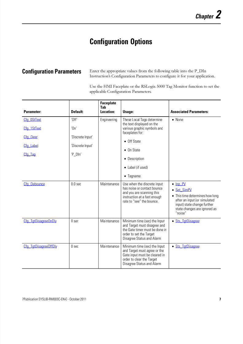
Configuration Parameters Enter the appropriate values from the following table into the P_DInInstruction’s Configuration Parameters to configure it for your application.
Use the HMI Faceplate or the RSLogix 5000 Tag Monitor function to set theapplicable Configuration Parameters.
Parameter: Default:
FaceplateTabLocation: Usage: Associated Parameters:
Cfg_0StText
Cfg_1StText
Cfg_Desc
Cfg_Label
Cfg_Tag
’Off’
’On’
’Discrete Input’
’Discrete Input’
’P_DIn’
Engineering These Local Tags determinethe text displayed on thevarious graphic symbols andfaceplates for:
• Off State
• On State
• Description
• Label (if used)
• Tagname
• None
Cfg_Debounce 0.0 sec Maintenance Use when the discrete inputhas noise or contact bounceand you are scanning thisinstruction at a fast enoughrate to “see” the bounce.
• Inp_PV
• Set_SimPV
• This time determines how longafter an input (or simulatedinput) state change furtherstate changes are ignored as“noise”
Cfg_TgtDisagreeOnDly 0 sec Maintenance Minimum time (sec) the Inputand Target must disagree andthe Gate timer must be done inorder to set the TargetDisagree Status and Alarm
• Sts_TgtDisagree
Cfg_TgtDisagreeOffDly 0 sec Maintenance Minimum time (sec) the Inputand Target must agree or theGate input must be cleared inorder to clear the TargetDisagree Status and Alarm
• Sts_TgtDisagree
8/20/2019 P DIn Instruction Manual
http://slidepdf.com/reader/full/p-din-instruction-manual 20/52
8 Publication SYSLIB-RM003C-EN-E - October 2011
Chapter 2 Configuration Options
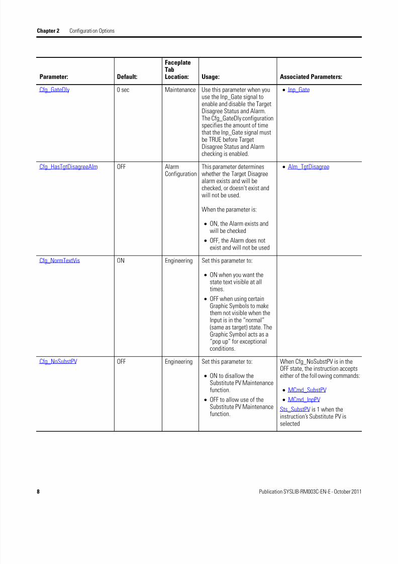
Cfg_GateDly 0 sec Maintenance Use this parameter when you
use the Inp_Gate signal toenable and disable the TargetDisagree Status and Alarm.The Cfg_GateDly configurationspecifies the amount of timethat the Inp_Gate signal mustbe TRUE before TargetDisagree Status and Alarmchecking is enabled.
• Inp_Gate
Cfg_HasTgtDisagreeAlm OFF AlarmConfiguration
This parameter determineswhether the Target Disagreealarm exists and will bechecked, or doesn’t exist and
will not be used.
When the parameter is:
• ON, the Alarm exists andwill be checked
• OFF, the Alarm does notexist and will not be used
• Alm_TgtDisagree
Cfg_NormTextVis ON Engineering Set this parameter to:
• ON when you want thestate text visible at alltimes.
• OFF when using certainGraphic Symbols to makethem not visible when theInput is in the “normal”(same as target) state. TheGraphic Symbol acts as a“pop up” for exceptionalconditions.
Cfg_NoSubstPV OFF Engineering Set this parameter to:
• ON to disallow theSubstitute PV Maintenancefunction.
• OFF to allow use of theSubstitute PV Maintenancefunction.
When Cfg_NoSubstPV is in theOFF state, the instruction acceptseither of the following commands:
• MCmd_SubstPV
• MCmd_InpPV
Sts_SubstPV is 1 when theinstruction’s Substitute PV isselected
Parameter: Default:
FaceplateTabLocation: Usage: Associated Parameters:
8/20/2019 P DIn Instruction Manual
http://slidepdf.com/reader/full/p-din-instruction-manual 21/52
Publication SYSLIB-RM003C-EN-E - October 2011 9
Configuration Options Chapter 2
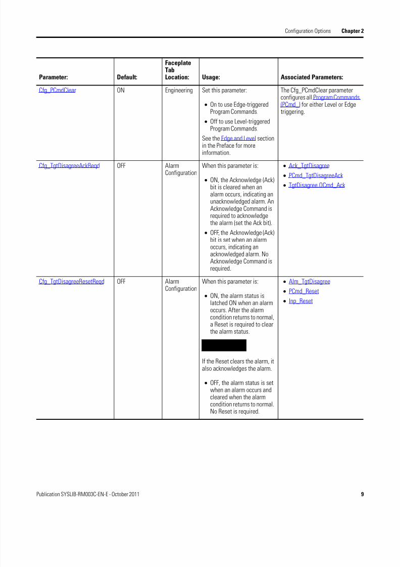
Cfg_PCmdClear ON Engineering Set this parameter:
• On to use Edge-triggeredProgram Commands.
• Off to use Level-triggeredProgram Commands.
See the Edge and Level sectionin the Preface for moreinformation.
The Cfg_PCmdClear parameter
configures all Program Commands(PCmd_) for either Level or Edgetriggering.
Cfg_TgtDisagreeAckReqd OFF AlarmConfiguration
When this parameter is:
• ON, the Acknowledge (Ack)bit is cleared when analarm occurs, indicating anunacknowledged alarm. AnAcknowledge Command isrequired to acknowledgethe alarm (set the Ack bit).
• OFF, the Acknowledge (Ack)bit is set when an alarmoccurs, indicating anacknowledged alarm. NoAcknowledge Command isrequired.
• Ack_TgtDisagree
• PCmd_TgtDisagreeAck
• TgtDisagree.OCmd_Ack
Cfg_TgtDisagreeResetReqd OFF AlarmConfiguration
When this parameter is:
• ON, the alarm status islatched ON when an alarmoccurs. After the alarmcondition returns to normal,a Reset is required to clearthe alarm status.
IMPORTANT
If the Reset clears the alarm, italso acknowledges the alarm.
• OFF, the alarm status is setwhen an alarm occurs and
cleared when the alarmcondition returns to normal.No Reset is required.
• Alm_TgtDisagree
• PCmd_Reset
• Inp_Reset
Parameter: Default:
FaceplateTabLocation: Usage: Associated Parameters:

8/20/2019 P DIn Instruction Manual
http://slidepdf.com/reader/full/p-din-instruction-manual 22/52
10 Publication SYSLIB-RM003C-EN-E - October 2011
Chapter 2 Configuration Options
Cfg_TgtDisagreeSeverity 3 Alarm
Configuration
This parameter determines the
Severity of the Target Disagreealarm, and thus the color ofalarm animations for the alarm. Valid values are:
• 1 = Information (blue)
• 2 = Warning (yellow)
• 3 = Exception (red)
• 4 = Fault (magenta)
• Val_Notify
Parameter: Default:
FaceplateTabLocation: Usage: Associated Parameters:

8/20/2019 P DIn Instruction Manual
http://slidepdf.com/reader/full/p-din-instruction-manual 23/52
11Publication SYSLIB-RM003C-EN-E - October 2011 11
Chapter 3
Instruction Data Reference
This chapter describes the P_DIn Instruction’s public parameters.
The descriptions in the tables below show how these data elements are used with the P_DIn Add-On Instruction.
Execution Execution parameters are included with every Add-On Instruction. See theLogix5000 Controllers Add-On Instructions Programming Reference Manual,publication 1756-PM010, for more information on these data elements.
Name: Data Type: Usage: Default: Style: Description:
AssociatedConfigurationParameter
EnableIn BOOL Input 1 Enable Input:1 = Normal scan. The instruction updates
status and generates alarms.0 = Inverts signal Inp_PV to allow mapping
input using XIC/XIO on LD rung.
EnableOut BOOL Output 0 Enable Output: The EnableOut signal is notmanipulated by this instruction. Its outputstate always reflects the EnableIn input state.
Inf_Tab SINT Output 0 Tab to display (FTView ME)
Inf_Type STRING_16 Output ’P_DIn’ Must contain AOI name, used for HMI andInformation S/W
P_DIn BOOL Output 0 Unique Parameter Name for auto - discovery
8/20/2019 P DIn Instruction Manual
http://slidepdf.com/reader/full/p-din-instruction-manual 24/52
12 Publication SYSLIB-RM003C-EN-E - October 2011
Chapter 3 Instruction Data Reference
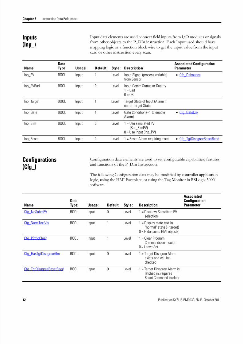
Inputs
(Inp_)
Input data elements are used connect field inputs from I/O modules or signalsfrom other objects to the P_DIn instruction. Each Input used should havemapping logic or a function block wire to get the input value from the inputcard or other instruction every scan.
Configurations
(Cfg_)
Configuration data elements are used to set configurable capabilities, featuresand functions of the P_DIn Instruction.
The following Configuration data may be modified by controller application
logic, using the HMI Faceplate, or using the Tag Monitor in RSLogix 5000software.
Name:DataType: Usage: Default: Style: Description:
Associated ConfigurationParameter
Inp_PV BOOL Input 1 Level Input Signal (process variable)from Sensor
• Cfg_Debounce
Inp_PVBad BOOL Input 0 Level Input Comm Status or Quality 1 = Bad 0 = OK
Inp_Target BOOL Input 1 Level Target State of Input (Alarm ifnot in Target State)
Inp_Gate BOOL Input 1 Level Gate Condition (=1 to enableAlarm)
• Cfg_GateDly
Inp_Sim BOOL Input 0 Level 1 = Use simulated PV(Set_SimPV)
0 = Use Input (Inp_PV)
Inp_Reset BOOL Input 0 Level 1 = Reset Alarm requiring reset • Cfg_TgtDisagreeResetReqd
Name:DataType: Usage: Default: Style: Description:
AssociatedConfigurationParameter
Cfg_NoSubstPV BOOL Input 0 Level 1 = Disallow Substitute PVselection.
Cfg_NormTextVis BOOL Input 1 Level 1 = Display state text in"normal" state (= target)
0 = Hide (some HMI objects)
Cfg_PCmdClear BOOL Input 1 Level 1 = Clear ProgramCommands on receipt
0 = Leave Set
Cfg_HasTgtDisagreeAlm BOOL Input 0 Level 1 = Target Disagree Alarmexists and will bechecked
Cfg_TgtDisagreeResetReqd BOOL Input 0 Level 1 = Target Disagree Alarm islatched in, requiresReset Command to clear

8/20/2019 P DIn Instruction Manual
http://slidepdf.com/reader/full/p-din-instruction-manual 25/52
Publication SYSLIB-RM003C-EN-E - October 2011 13
Instruction Data Reference Chapter 3
Cfg_TgtDisagreeAckReqd BOOL Input 1 Level 1 = Target Disagree Alarmmust be acknowledged
Cfg_TgtDisagreeSeverity SINT Input 3 Decimal Target Disagree AlarmSeverity: 1 = Information 2 = Warning 3 = Exception 4 = Fault
Cfg_GateDly DINT Input 0 Decimal Time Inp_Gate must be truebefore Alarm is checked (sec)
Cfg_Debounce REAL Input 0.0 Float Minimum time Status mustmaintain state, (sec)
Cfg_TgtDisagreeOnDly DINT Input 0 Decimal Minimum time for Input to
disagree with Target to raiseStatus (sec)
Cfg_TgtDisagreeOffDly DINT Input 0 Decimal Minimum time for Input toagree with Target to clearStatus (sec)
Name:DataType: Usage: Default: Style: Description:
AssociatedConfigurationParameter

8/20/2019 P DIn Instruction Manual
http://slidepdf.com/reader/full/p-din-instruction-manual 26/52
14 Publication SYSLIB-RM003C-EN-E - October 2011
Chapter 3 Instruction Data Reference
Configurations in Local Tags
Because they contain arrayed or structured data types, the followingConfiguration data elements use P_DIn Add-On Instruction Local Tags.
These may be modified using RSLogix 5000 or using the HMI Faceplates, butcannot be modified using controller logic:
Operator Settings, Maintenance Settings, Other Settings
(OSet_, MSet_, Set_)
Operator, Maintenance and Other Setting data elements are used by the HMIfaceplate to let the operator establish setpoints, thresholds and other settingsof the P_DIn Instruction.
Name: Data Type: Usage: Default: Style: Description:
AssociatedConfigurationParameter
Cfg_0StText STRING_8 ’Off’ String Text to display in PV 0 State
Cfg_1StText STRING_8 ’On’ String Text to display in PV 1State
Cfg_Desc STRING_40 ’Discrete Input’ String Description for display on HMI
Cfg_Label STRING_20 ’Discrete Input’ String Label for graphic symbol displayed onHMI
Cfg_Tag STRING_20 ’P_DIn’ String Tagname for display on HMI
Name:DataType: Usage: Default: Style: Description:
AssociatedConfigurationParameter
MSet_SubstPV BOOL Input 0 Level Operator-Entered Substitute PV • Cfg_NoSubstPV
Set_SimPV BOOL Input 0 Level PV used in Simulation (Inp_Sim=1) • Cfg_Debounce

8/20/2019 P DIn Instruction Manual
http://slidepdf.com/reader/full/p-din-instruction-manual 27/52
Publication SYSLIB-RM003C-EN-E - October 2011 15
Instruction Data Reference Chapter 3
Program Commands(PCmd_)
Program Command Data Elements are used by application logic to requestP_DIn Instruction actions, such as acknowledging alarms, or specific P_DInactions. Application logic sets the Program Command to 1 to request theaction. (See the Edge and Level section in the Preface for more information).The P_DIn Instruction then performs the requested action if the action canbe performed.
Alarm Commands
* Primary Function: If Cfg_PCmdClear = 0, triggered by Level = 1 If Cfg_PCmdClear = 1, triggered by rising Edge
* * Opposite Function: If Cfg_PCmdClear = 0, triggered by primary function bit Level = 0 (this bit NOT USED)
If Cfg_PCmdClear = 1, triggered by rising Edge of this bit
Name:DataType: Usage: Default: Style: Description:
Associated ConfigurationParameter
PCmd_Reset BOOL Input 0 * Program Command toReset all latched Alarms
PCmd_TgtDisagreeAck BOOL Input 0 * Program Command toAcknowledge the TargetDisagree Alarm
• Cfg_TgtDisagreeAckReqd
PCmd_TgtDisagreeInhibit BOOL Input 0 * Program Command toInhibit the Target DisagreeAlarm
PCmd_Tgt DisagreeUninhibit BOOL Input 0 ** Program Command toUninhibit the TargetDisagree Alarm

8/20/2019 P DIn Instruction Manual
http://slidepdf.com/reader/full/p-din-instruction-manual 28/52
16 Publication SYSLIB-RM003C-EN-E - October 2011
Chapter 3 Instruction Data Reference
Operator Commands, Maintenance Commands, Command Readies
(OCmd_, MCmd_, Rdy_)
Operator Commands and Maintenance Commands are used by the operator atthe HMI to request instruction actions, such as acknowledging, enabling ordisabling, suppressing or unsuppressing alarms; or other instruction-specificactions. These Commands are set (latched) by the HMI and are read and thencleared (unlatched) and acted upon by the P_DIn instruction, allowing amany-to-one relationship between HMI requestors and each Command.Commands are implemented as public Input Parameters of the instruction oras Input Parameters of instructions internal to the P_DIn instruction("embedded Commands").
Device Commands
Alarm Commands
Name:
Data
Type: Usage: Default: Style: Description:
AssociatedConfiguration
ParameterMCmd_SubstPV BOOL Input 0 Edge Maintenance Command to use
Substitute PV (override input)• Cfg_NoSubstPV
MCmd_InpPV BOOL Input 0 Edge Maintenance Command to use Input PV(normal)
• Cfg_NoSubstPV
IMPORTANT
Alarm Commands are sent to P_Alarm Instructions embedded
within the P_DIn Instruction. Each P_Alarm Instruction instanceis named for the alarm condition.
Name:DataType: Usage: Default: Style: Description:
Associated ConfigurationParameter
OCmd_Reset BOOL Input 0 Edge Operator Command toReset all latched Alarms
• Cfg_TgtDisagreeResetReqd
OCmd_ResetAckAll BOOL Input 0 Edge Operator Command toReset and Acknowledge allAlarms
TgtDisagree.OCmd_Reset BOOL Input 0 Edge Operator Command toReset latched TargetDisagree Alarm
• Cfg_TgtDisagreeResetReqd

8/20/2019 P DIn Instruction Manual
http://slidepdf.com/reader/full/p-din-instruction-manual 29/52
Publication SYSLIB-RM003C-EN-E - October 2011 17
Instruction Data Reference Chapter 3
Device Command Readies
TgtDisagree.OCmd_Ack BOOL Input 0 Edge Operator Command toAcknowledge TargetDisagree Alarm
• Cfg_TgtDisagreeAckReqd
• Cfg_HasTgtDisagreeAlm
TgtDisagree.OCmd_Disable BOOL Input 0 Edge Operator Command toDisable Target DisagreeAlarm
TgtDisagree.OCmd_Enable BOOL Input 0 Edge Operator Command toEnable Target DisagreeAlarm
Name:DataType: Usage: Default: Style: Description:
Associated ConfigurationParameter
IMPORTANT Each Operator or Maintenance Command has a correspondingReady bit which indicates whether the Command will beaccepted and acted upon when received. The Ready bit is usedto enable (1) or gray-out (0) the Operator Command button onthe Faceplate.
Name:DataType: Usage: Default: Style: Description:
AssociatedConfigurationParameter
Rdy_SubstPV BOOL Output 0 1 = Ready for MCmd_SubstPV (enablesHMI button)
Rdy_InpPV BOOL Output 0 1 = Ready for MCmd_InpPV (enablesHMI button)
8/20/2019 P DIn Instruction Manual
http://slidepdf.com/reader/full/p-din-instruction-manual 30/52
18 Publication SYSLIB-RM003C-EN-E - October 2011
Chapter 3 Instruction Data Reference
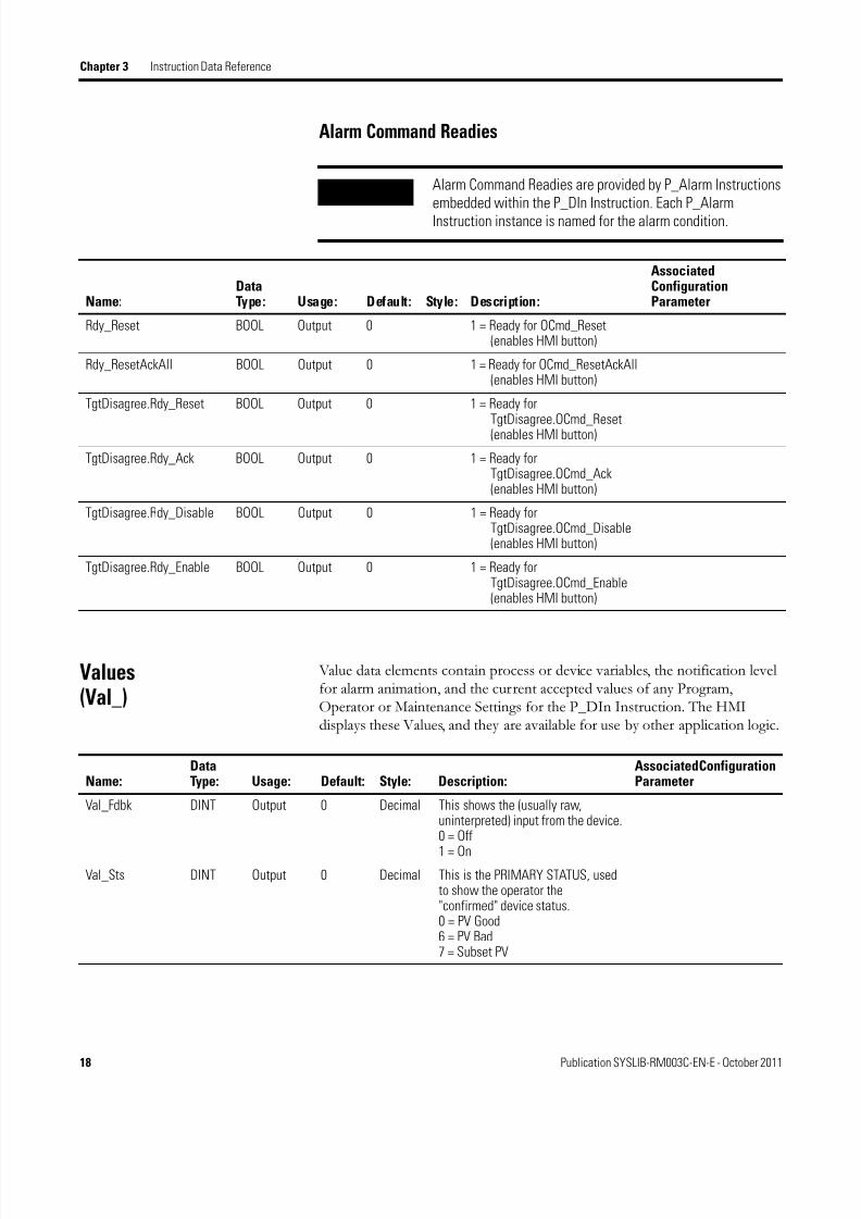
Alarm Command Readies
Values
(Val_)
Value data elements contain process or device variables, the notification levelfor alarm animation, and the current accepted values of any Program,Operator or Maintenance Settings for the P_DIn Instruction. The HMIdisplays these Values, and they are available for use by other application logic.
IMPORTANT Alarm Command Readies are provided by P_Alarm Instructionsembedded within the P_DIn Instruction. Each P_AlarmInstruction instance is named for the alarm condition.
Name:DataType: Usage: Default: Style: Description:
AssociatedConfigurationParameter
Rdy_Reset BOOL Output 0 1 = Ready for OCmd_Reset(enables HMI button)
Rdy_ResetAckAll BOOL Output 0 1 = Ready for OCmd_ResetAckAll(enables HMI button)
TgtDisagree.Rdy_Reset BOOL Output 0 1 = Ready forTgtDisagree.OCmd_Reset(enables HMI button)
TgtDisagree.Rdy_Ack BOOL Output 0 1 = Ready forTgtDisagree.OCmd_Ack(enables HMI button)
TgtDisagree.Rdy_Disable BOOL Output 0 1 = Ready forTgtDisagree.OCmd_Disable(enables HMI button)
TgtDisagree.Rdy_Enable BOOL Output 0 1 = Ready forTgtDisagree.OCmd_Enable(enables HMI button)
Name:DataType: Usage: Default: Style: Description:
Associated ConfigurationParameter
Val_Fdbk DINT Output 0 Decimal This shows the (usually raw,uninterpreted) input from the device. 0 = Off
1 = OnVal_Sts DINT Output 0 Decimal This is the PRIMARY STATUS, used
to show the operator the"confirmed" device status. 0 = PV Good 6 = PV Bad 7 = Subset PV

8/20/2019 P DIn Instruction Manual
http://slidepdf.com/reader/full/p-din-instruction-manual 31/52
8/20/2019 P DIn Instruction Manual
http://slidepdf.com/reader/full/p-din-instruction-manual 32/52
20 Publication SYSLIB-RM003C-EN-E - October 2011
Chapter 3 Instruction Data Reference
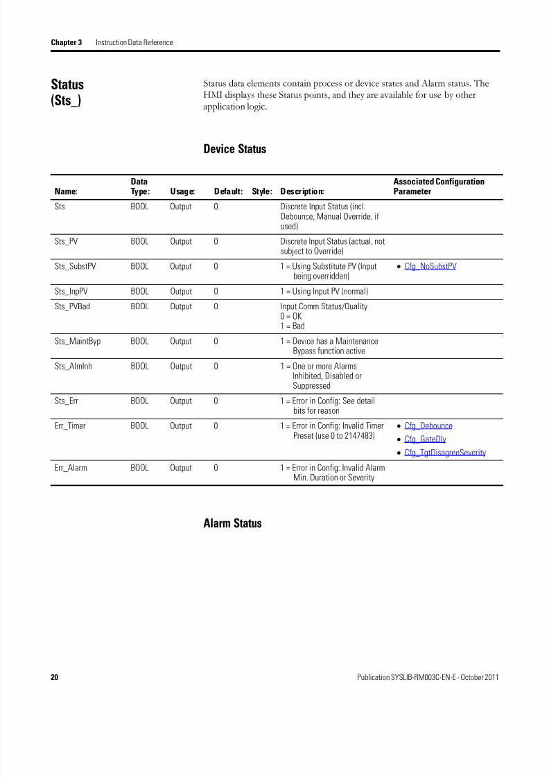
Status
(Sts_)
Status data elements contain process or device states and Alarm status. TheHMI displays these Status points, and they are available for use by otherapplication logic.
Device Status
Alarm Status
Name:DataType: Usage: Default: Style: Description:
Associated ConfigurationParameter
Sts BOOL Output 0 Discrete Input Status (incl.Debounce, Manual Override, ifused)
Sts_PV BOOL Output 0 Discrete Input Status (actual, notsubject to Override)
Sts_SubstPV BOOL Output 0 1 = Using Substitute PV (Inputbeing overridden)
• Cfg_NoSubstPV
Sts_InpPV BOOL Output 0 1 = Using Input PV (normal)
Sts_PVBad BOOL Output 0 Input Comm Status/Quality 0 = OK 1 = Bad
Sts_MaintByp BOOL Output 0 1 = Device has a MaintenanceBypass function active
Sts_AlmInh BOOL Output 0 1 = One or more AlarmsInhibited, Disabled orSuppressed
Sts_Err BOOL Output 0 1 = Error in Config: See detail
bits for reason
Err_Timer BOOL Output 0 1 = Error in Config: Invalid TimerPreset (use 0 to 2147483)
• Cfg_Debounce
• Cfg_GateDly
• Cfg_TgtDisagreeSeverity
Err_Alarm BOOL Output 0 1 = Error in Config: Invalid AlarmMin. Duration or Severity

8/20/2019 P DIn Instruction Manual
http://slidepdf.com/reader/full/p-din-instruction-manual 33/52
Publication SYSLIB-RM003C-EN-E - October 2011 21
Instruction Data Reference Chapter 3
Name:DataType: Usage: Default: Style: Description:
Associated ConfigurationParameter
Sts_TgtDisagree BOOL Output 0 1 = Input is not in Targetstate
Alm_TgtDisagree BOOL Output 0 1 = Discrete Input TargetDisagree Alarm
• Cfg_TgtDisagreeResetReqd
Ack_TgtDisagree BOOL Output 0 1 = Target DisagreeAlarmAcknowledged
• Cfg_TgtDisagreeAckReqd
Sts_TgtDisagreeDisabled BOOL Output 0 1 = Target DisagreeAlarm Disabled (notsaved or sent)
Sts_TgtDisagreeInhibited BOOL Output 0 1 = Target DisagreeAlarm Inhibited byLogic
Sts_TgtDisagreeSuppressed BOOL Output 0 1 = Target Disagree
Alarm Suppressed(logged only)

8/20/2019 P DIn Instruction Manual
http://slidepdf.com/reader/full/p-din-instruction-manual 34/52
22 Publication SYSLIB-RM003C-EN-E - October 2011
Chapter 3 Instruction Data Reference
Notes:
8/20/2019 P DIn Instruction Manual
http://slidepdf.com/reader/full/p-din-instruction-manual 35/52
23Publication SYSLIB-RM003C-EN-E - October 2011 23
Chapter 4
HMI Reference
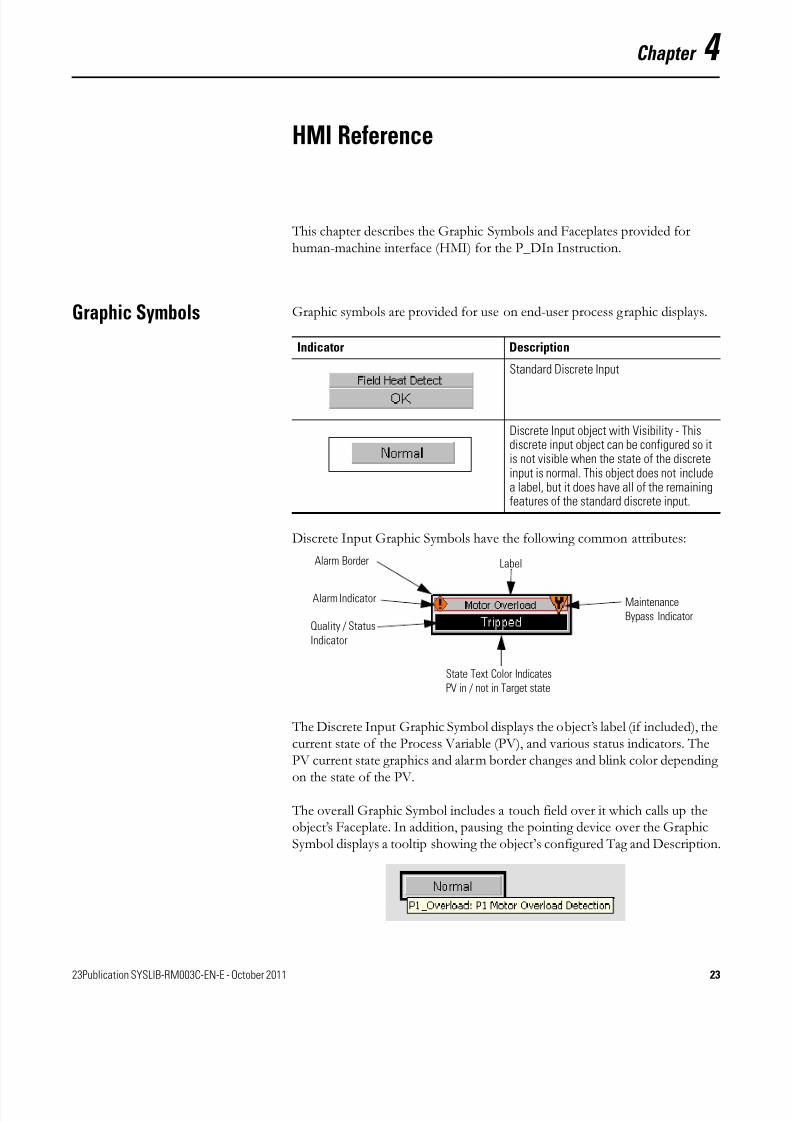
This chapter describes the Graphic Symbols and Faceplates provided forhuman-machine interface (HMI) for the P_DIn Instruction.
Graphic Symbols Graphic symbols are provided for use on end-user process graphic displays.
Discrete Input Graphic Symbols have the following common attributes:
The Discrete Input Graphic Symbol displays the object’s label (if included), thecurrent state of the Process Variable (PV), and various status indicators. ThePV current state graphics and alarm border changes and blink color dependingon the state of the PV.
The overall Graphic Symbol includes a touch field over it which calls up theobject’s Faceplate. In addition, pausing the pointing device over the GraphicSymbol displays a tooltip showing the object’s configured Tag and Description.
Indicator Description
Standard Discrete Input
Discrete Input object with Visibility - Thisdiscrete input object can be configured so itis not visible when the state of the discreteinput is normal. This object does not includea label, but it does have all of the remainingfeatures of the standard discrete input.
Alarm Indicator
Quality / Status
Indicator
State Text Color Indicates
PV in / not in Target state
Label
Maintenance
Bypass Indicator
Alarm Border

8/20/2019 P DIn Instruction Manual
http://slidepdf.com/reader/full/p-din-instruction-manual 36/52
24 Publication SYSLIB-RM003C-EN-E - October 2011
Chapter 4 HMI Reference
Process Variable State Indicator
User-configurable text is shown for the On state and the Off state of thediscrete Process Variable (PV). In addition, the text changes color depending
on the PV state and the Target input state:
Status / Quality Indicators
One of these symbols appears to the left of the Process Variable when thedescribed condition is true
TIP
When the Invalid Configuration Indicator appears, you can find whatconfiguration setting is invalid by following the indicators like a "trail ofbreadcrumbs". Click the Graphic Symbol to call up the Faceplate. The InvalidConfiguration indicator will appear next to the appropriate tab at the top of theFaceplate to guide you in finding the configuration error. Once you navigate to thetab, the misconfigured item will be flagged with this indicator or appear in amagenta box.
Color State
Black text on light gray PV state matches Target state
White or alarm color text on black PV state does not match Target state
Indicator Description
Invalid Configuration
PV Quality Bad: Communication Failure
Input matches Target
Input does not match Target
No symboldisplayed
No Invalid Configuration and PV Quality Good

8/20/2019 P DIn Instruction Manual
http://slidepdf.com/reader/full/p-din-instruction-manual 37/52
Publication SYSLIB-RM003C-EN-E - October 2011 25
HMI Reference Chapter 4
For the Discrete Input Instruction, the Invalid Configuration Indicatorappears under the following conditions:
• The Debounce Time is set to a value less than zero or greater than2,147,483 seconds.
• The Alarm Gate Delay is set to a value less than zero or greater than2,147,483 seconds.
• The Alarm Minimum Duration is set to a value less than zero or greaterthan 2,147,483 seconds.
• An Alarm Severity is set to a value other than 1 (information), 2(warning), 3 (exception) or 4 (fault).
Maintenance Bypass Indicator
This symbol appears to the right of the Label or Process Variable to indicatethat a Maintenance Bypass has been activated:
TIP
When the Maintenance Bypass Indicator appears, you can find what condition
was bypassed by following the indicators like a "trail of breadcrumbs". Click theGraphic Symbol to call up the Faceplate. The Maintenance Bypass Indicator willappear next to the appropriate tab at the top of the Faceplate to guide you infinding the bypass. Once you navigate to the tab, the bypassed item will beflagged with this indicator.
For the Discrete Input Instruction, the Maintenance Bypass Indicator appearsunder the following condition:
• The Substitute PV function has been enabled. The "live" Process Variable is being superseded by a Maintenance-entered value.
Graphic Symbol Description
A Maintenance Bypass is active
No symbol displayed No Maintenance Bypass active

8/20/2019 P DIn Instruction Manual
http://slidepdf.com/reader/full/p-din-instruction-manual 38/52
26 Publication SYSLIB-RM003C-EN-E - October 2011
Chapter 4 HMI Reference
Alarm Indicators
One of these symbols appears to the left of the Label to indicate the describedalarm condition. The alarm border and label background blink if
Acknowledgement of an alarm condition is required.
Symbol Description
Black "I" in white box with blackborder
Alarm Inhibit: an alarm is Inhibited by theProgram, Disabled by Maintenance orSuppressed by the Operator.
White bell, border, and textbackground
Return to Normal (no Alarm condition), but aprevious Alarm has not been acknowledged
Blue border and text backgroundYellow rectangle with exclamation
point (!)
Information Severity Alarm
Yellow border and text backgroundOrange triangle with exclamationpoint (!)
Warning Severity Alarm
Red border and text backgroundOrange diamond with exclamationpoint (!)
Exception Severity Alarm
Magenta border and text backgroundRed circle with two exclamationpoints (!!)
Fault Severity Alarm
No symbol or border displayed, text is onnormal (light gray) background, not blinking
No Alarm or Alarm Inhibit condition, and allAlarms are Acknowledged

8/20/2019 P DIn Instruction Manual
http://slidepdf.com/reader/full/p-din-instruction-manual 39/52
Publication SYSLIB-RM003C-EN-E - October 2011 27
HMI Reference Chapter 4
Using Graphics Symbols
The graphic symbol for P_DIn can be found in the global object file(RA-BAS) Process Graphics Library.ggfx. To use the graphic symbol, copy it
from the global object file and paste it in the display file. Next, right click onthe global object file in the display file and select "Global Object Parameter Values" and the following window appears:
Enter the tag(s) in the "Value" column as specified in the "Description"column.
Note: Values for items marked ‘(optional)’ may be left blank.
Faceplate The Discrete Input Faceplate consists of five tabbed pages. The Operator tabis displayed when the Faceplate is initially called up. Click the appropriate iconat the top of the screen to access a specific tab.
The Faceplate provides the means for Operators, Maintenance, Engineers andothers to interact with the P_DIn Instruction instance, including viewing itsStatus and Values and manipulating it through its Commands and Settings. When a given input is restricted via FactoryTalk View security, the requireduser Security Code letter is shown in the tables that follow.
Operator Engineering
Maintenance
Alarms
Alarms Configuration Help
Exit
8/20/2019 P DIn Instruction Manual
http://slidepdf.com/reader/full/p-din-instruction-manual 40/52
28 Publication SYSLIB-RM003C-EN-E - October 2011
Chapter 4 HMI Reference
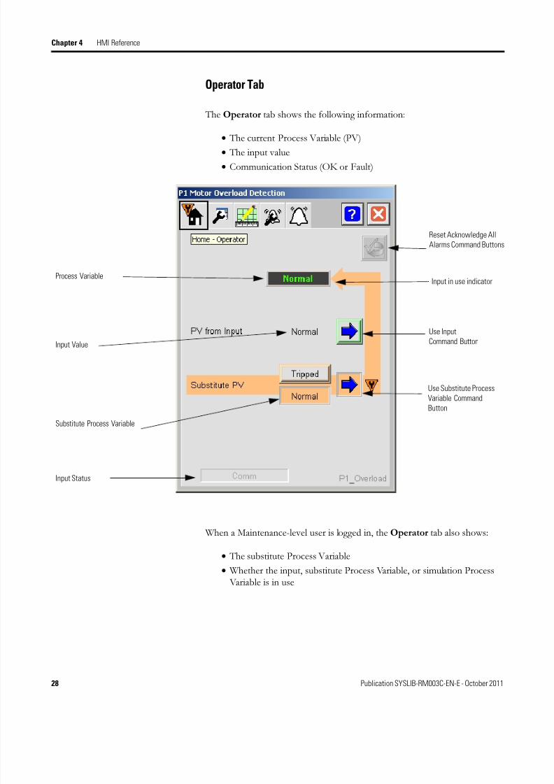
Operator Tab
The Operator tab shows the following information:
• The current Process Variable (PV)• The input value
• Communication Status (OK or Fault)
When a Maintenance-level user is logged in, the Operator tab also shows:
• The substitute Process Variable
• Whether the input, substitute Process Variable, or simulation Process Variable is in use
Process Variable
Input Value
Substitute Process Variable
Input in use indicator
Use Input
Command Button
Use Substitute Process
Variable Command
Button
Input Status
Reset Acknowledge All
Alarms Command Buttons
8/20/2019 P DIn Instruction Manual
http://slidepdf.com/reader/full/p-din-instruction-manual 41/52
Publication SYSLIB-RM003C-EN-E - October 2011 29
HMI Reference Chapter 4
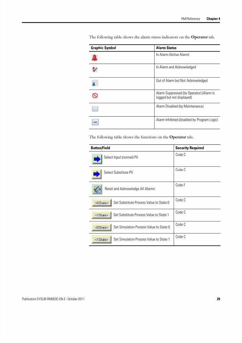
The following table shows the alarm status indicators on the Operator tab.
The following table shows the functions on the Operator tab:.
Graphic Symbol Alarm Status
In Alarm (Active Alarm)
In Alarm and Acknowledged
Out of Alarm but Not Acknowledged
Alarm Suppressed (by Operator) (Alarm islogged but not displayed)
Alarm Disabled (by Maintenance)
Alarm Inhibited (disabled by Program Logic)
Button/Field Security Required
Select Input (normal) PVCode C
Select Substitute PVCode C
Reset and Acknowledge All AlarmsCode F
Set Substitute Process Value to State 0Code C
Set Substitute Process Value to State 1Code C
Set Simulation Process Value to State 0Code C
Set Simulation Process Value to State 1
Code C

8/20/2019 P DIn Instruction Manual
http://slidepdf.com/reader/full/p-din-instruction-manual 42/52
30 Publication SYSLIB-RM003C-EN-E - October 2011
Chapter 4 HMI Reference
Alarms Tab
The Alarms tab bell icon at the top of the Faceplate changes color based onthe current active alarms. The Alarms tab icon blinks if an alarm is
unacknowledged or if the device or one of its alarms needs to be reset.
The Alarms tab displays each alarm for this device. If the alarm is active, thepanel behind the alarm will change color to match the severity of the alarm.
Alarm Acknowledge
Command Button
Reset and
Acknowledge AllAlarms Command
Button
Color Definition
Magenta Fault
Red Exception
Yellow Warning
Blue Information
Background (Light Gray) No alarm

8/20/2019 P DIn Instruction Manual
http://slidepdf.com/reader/full/p-din-instruction-manual 43/52
Publication SYSLIB-RM003C-EN-E - October 2011 31
HMI Reference Chapter 4
The following table lists the functions on the Alarm tab.
The panel behind the alarm blinks if the alarm requires acknowledgement.Click the button with the check mark to acknowledge the alarm.
Each Alarm Acknowledge button is enabled if the corresponding Alarmrequires acknowledgement.
The Reset and Acknowledge All Alarms button is enabled if any alarmrequires reset or acknowledgement.
Button Action Security Required
Alarm Acknowledge Code F
Reset and Acknowledge AllAlarms
Code F

8/20/2019 P DIn Instruction Manual
http://slidepdf.com/reader/full/p-din-instruction-manual 44/52
32 Publication SYSLIB-RM003C-EN-E - October 2011
Chapter 4 HMI Reference
Maintenance Tab
The Maintenance tab shows the following information:
• Current Process Variable
• Input Process Variable (or Simulated Process Variable when simulationis enabled)
• Selected and debounced Input Process Variable
• Target Process Variable
• Gate Enabled/Disabled State
• Animation highlights how the final PV Current Value was determined

8/20/2019 P DIn Instruction Manual
http://slidepdf.com/reader/full/p-din-instruction-manual 45/52
Publication SYSLIB-RM003C-EN-E - October 2011 33
HMI Reference Chapter 4
The Discrete Input alarm status appears on the Maintenance tab. The
following table shows the alarm status indicators:
The following table shows the data entries available on the Maintenance tab.
Graphic Symbol Alarm Status
In Alarm (Active Alarm)
In Alarm and Acknowledged
Out of Alarm but Not Acknowledged
Alarm Suppressed (by Operator) (Alarm islogged but not displayed)
Alarm Disabled (by Maintenance)
Alarm Inhibited (by Program logic)
Field Security Required
Gate Delay (seconds) Code D
Debounce Time (seconds) Code D
Target Disagree Status On Delay (seconds)
Code D
Target Disagree Status Off Delay (seconds)
Code D
8/20/2019 P DIn Instruction Manual
http://slidepdf.com/reader/full/p-din-instruction-manual 46/52
34 Publication SYSLIB-RM003C-EN-E - October 2011
Chapter 4 HMI Reference
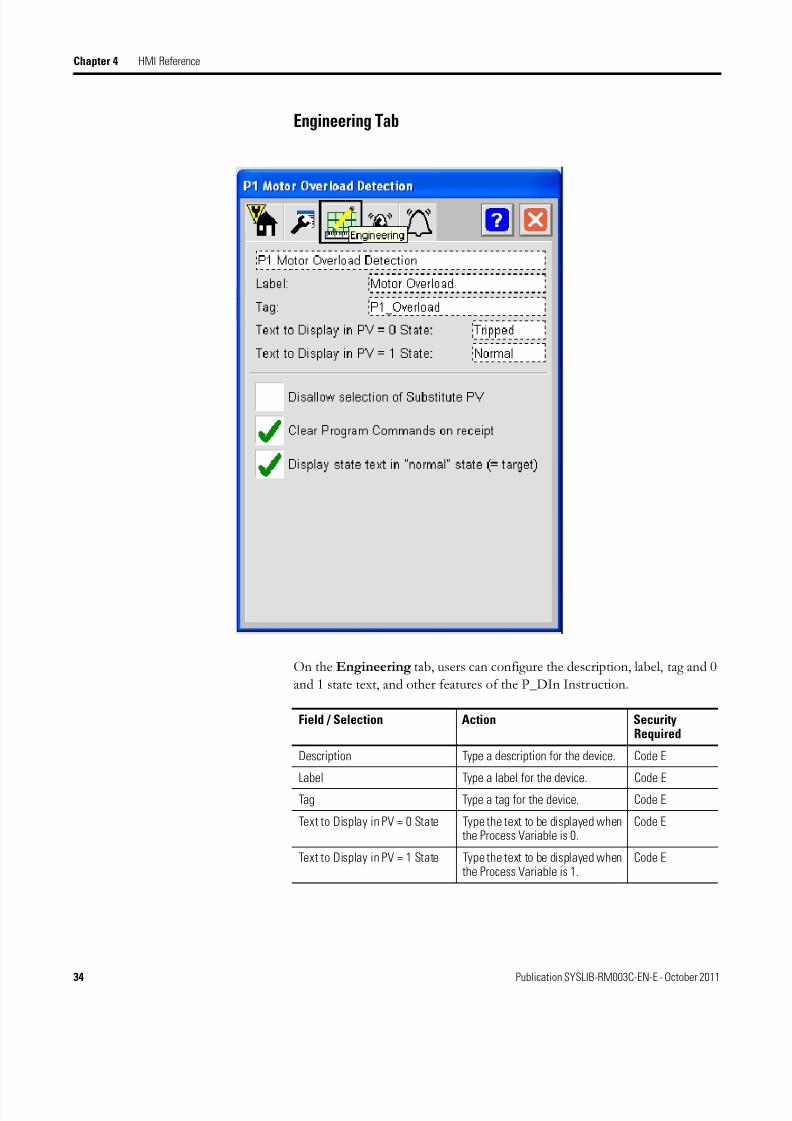
Engineering Tab
On the Engineering tab, users can configure the description, label, tag and 0
and 1 state text, and other features of the P_DIn Instruction.
Field / Selection Action SecurityRequired
Description Type a description for the device. Code E
Label Type a label for the device. Code E
Tag Type a tag for the device. Code E
Text to Display in PV = 0 State Type the text to be displayed whenthe Process Variable is 0.
Code E
Text to Display in PV = 1 State Type the text to be displayed whenthe Process Variable is 1.
Code E

8/20/2019 P DIn Instruction Manual
http://slidepdf.com/reader/full/p-din-instruction-manual 47/52
Publication SYSLIB-RM003C-EN-E - October 2011 35
HMI Reference Chapter 4
Disallow selection of SubstitutePV
Check this box to disallowMaintenance use of the SubstitutePV function.
Code E
Clear Program Commands onReceipt
Check this box to have theInstruction clear ProgramCommands on receipt (Edgetriggering).
Uncheck this box to leave ProgramCommands in their last state(Level triggering).
Code E
Display state text in "normal"state (when PV = Target)
For Graphic Symbols with visibility,check this box to display thesymbol regardless of whether thePV is in the Target state.
Uncheck this box to display thesymbol only when the PV is not inthe Target state.
Code E
Field / Selection Action SecurityRequired

8/20/2019 P DIn Instruction Manual
http://slidepdf.com/reader/full/p-din-instruction-manual 48/52
36 Publication SYSLIB-RM003C-EN-E - October 2011
Chapter 4 HMI Reference
Alarm Configuration Tab

8/20/2019 P DIn Instruction Manual
http://slidepdf.com/reader/full/p-din-instruction-manual 49/52
Publication SYSLIB-RM003C-EN-E - October 2011 37
HMI Reference Chapter 4
The Alarm Configuration tab contains configuration related to the alarms
for the device. For each alarm, the following attributes may be configured.
Check Box/Field Action SecurityRequired
Alarm The alarm exists for the device. Code E
Acknowledge Required Require acknowledgement of the alarm.
IMPORTANT
If using FTView Alarm and Events,configure its Alarm Tag for AcknowledgeRequired. The controller handlesacknowledgement within this instruction.
Code E
Reset Required Require a reset to clear the alarm status.There is a single alarm reset that resets
all of the alarms for the device.
IMPORTANT
If using FTView Alarms and Events, DONOT check the "Latched" checkbox as thecontroller handles the alarm reset withinthis instruction.
Code E
Severity Configure the severity level of the alarm: 1 = Information 2 = Warning 3 = Exception 4 = Fault
Code E
Minimum On Time When an Alarm occurs, the Alarm outputwill be held on for at least this amount oftime (sec). If set to 5 seconds or less, theAlarm output will be held on for at least 5seconds to ensure it is seen by polling.Set this time higher if you want an Alarmto be held in the Alarm state (and on theAlarm summary) longer. This will keep itvisible to the Operator, or keep the Alarmfrom clearing and being set again (for anintermittent condition) until the Operatorhas had time to perform anyAlarm-related actions.
Note: If the alarm is configured withReset Required (Cfg_ResetReqd = 1), theoperator can reset the alarm before thistime expires if the input condition hasreturned to normal.
Code D
8/20/2019 P DIn Instruction Manual
http://slidepdf.com/reader/full/p-din-instruction-manual 50/52
38 Publication SYSLIB-RM003C-EN-E - October 2011
Chapter 4 HMI Reference
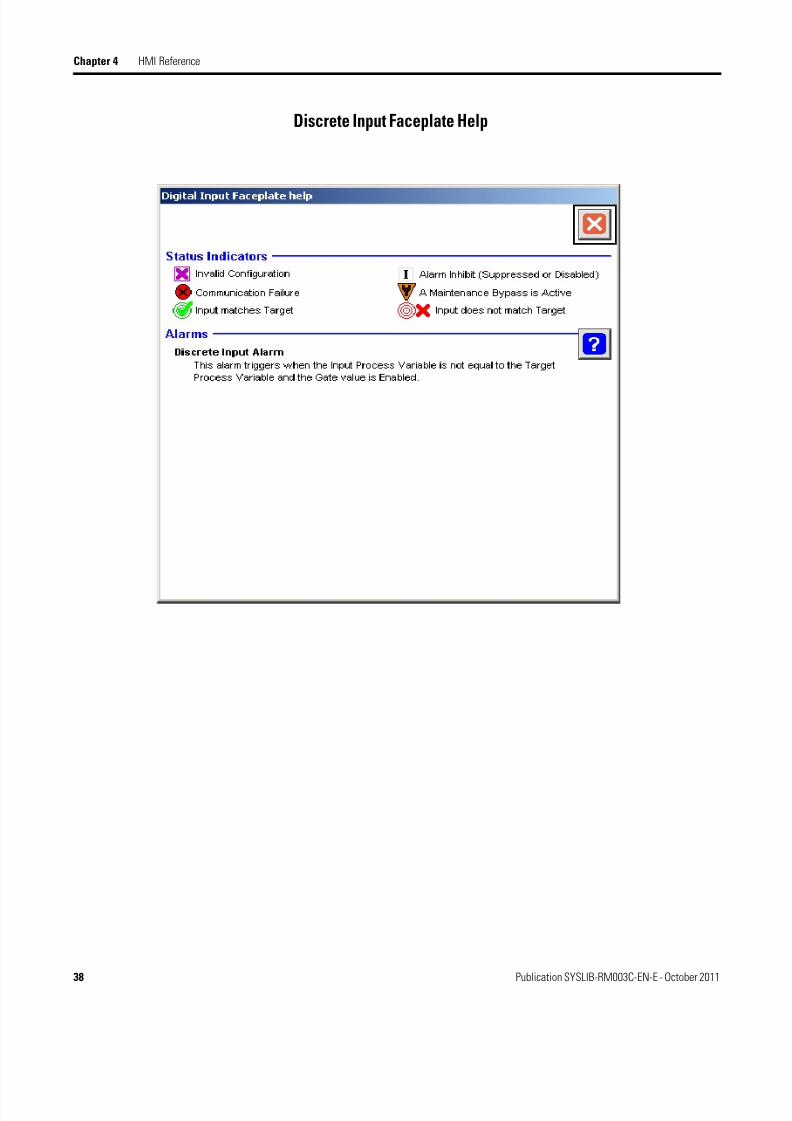
Discrete Input Faceplate Help

8/20/2019 P DIn Instruction Manual
http://slidepdf.com/reader/full/p-din-instruction-manual 51/52

8/20/2019 P DIn Instruction Manual
http://slidepdf.com/reader/full/p-din-instruction-manual 52/52
Rockwell Otomasyon Ticaret A.Ş., Kar Plaza ş Merkezi E Blok Kat:6 34752 çerenköy, stanbul, Tel: +90 (216) 5698400
Rockwell Automation Support
Rockwell Automation provides technical information on the Web to assist you in using its products.At http://www.rockwellautomation.com/support/, you can find technical manuals, a knowledge base of FAQs, technical andapplication notes, sample code and links to software service packs, and a MySupport feature that you can customize tomake the best use of these tools.
For an additional level of technical phone support for installation, configuration, and troubleshooting, we offerTechConnectSM support programs. For more information, contact your local distributor or Rockwell Automationrepresentative, or visit http://www.rockwellautomation.com/support/.
Installation Assistance
If you experience a problem within the first 24 hours of installation, review the information that is contained in thismanual. You can contact Customer Support for initial help in getting your product up and running.
New Product Satisfaction Return
Rockwell Automation tests all of its products to ensure that they are fully operational when shipped from themanufacturing facility. However, if your product is not functioning and needs to be returned, follow these procedures.
Documentation Feedback
Your comments will help us serve your documentation needs better. If you have any suggestions on how to improve thisdocument, complete this form, publication RA-DU002, available at http://www.rockwellautomation.com/literature/.
United States or Canada 1.440.646.3434
Outside United States or Canada Use the Worldwide Locator at http://www.rockwellautomation.com/support/americas/phone_en.html, or contact your local RockwellAutomation representative.
United States Contact your distributor. You must provide a Customer Support case number (call the phone number above to obtain one) to yourdistributor to complete the return process.
Outside United States Please contact your local Rockwell Automation representative for the return procedure.
www.rockwellautomation.com