p. national advisory committee for aeronauticsures 1 and 2. the wjng of the modol had an aspect...
TRANSCRIPT
/.
I
P.
e-*
FA
ABB No. 3F28
NATIONAL ADVISORY COMMITTEE FOR AERONAUTICS
WARTIME REPORT ORIGINALLY ISSUED
June 19^3 as Advance Bestrieted Eeport 3F28
EXPERIMENTAL DETERMINATION OF THE YAWING MOMENT DUE TO
YAWING CONTRIBUTED BY THE WING, FUSELAGE, AND
VERTICAL TAIL OF A MIDWING AIRPLANE MODEL
By John P. Campbell and Ward 0. Mathevs
Langley Memorial Aeronautical Laboratory Langley Field, Va.
" -1 <H51 SEPUIN0*
WASHINGTON
NACA WARTIME REPORTS are reprints of papers originally issued to provide rapid distribution of advance research results to an authorized group requiring them for the war effort. They were pre- viously held under a security status but are now unclassified. Some of these reports were not tech- nically edited. All have been reproduced without change in order to expedite general distribution.
L- 387
Date Due
Library Bg,Bau Cat. No. I
**V
*

NATIONAL ADVISORY COMMITTEE FOR AERONAUTICS
ADVANCE RESTRICTED REPORT
EXPERIMENTAL DETERMINATION OF THE YAWING MOMENT DUE TO CO '? YAWING CONTRIBUTED BY THE VING, FUSELAGE, AND
VERTICAL TAIL OF A MIDWING AIRPLANE MODEL
By John P. Campbell and Ward 0, Matbews
SUMMARY
Values of the lateral-stability derivative Cnr, the
rate of change of yawing-momer.t coefficient with yawing angular velocity, contributed 'by the wing, the fuselage, and the vertical tail have "been determined for a midwing airplane model by the free-cscillation method.
It was found that the values of Cn contributed by
the vertical tail and by the profile drag of the wing were in good agreement with theory. The damping contributed by the wing varied as the square of the lift coefficient, but the actual values were somewhat lower than those pre- dicted by existing theory, The value of Cn contributed
by the fuselage appeared to be negligible.
approximate value of Cn for a Conventional midwing air- in empirical formula is presented for obtaining an
plane.
INTRODUCTION
In calculating the lateral stability of an airplane, difficulty is often experienced in estimating values of the stability derivative Cn , the rate of change of yawing--moraent coefficient with yawing angular velocity. Al- though theoretical methods for obtaining the value of Cnr contributed by the vertical tail and the wing are given in references 1, 23 and 3, little recent experimental work has been dene to determine values of this derivative. In order to provide experimental data on the contributions of the wing, the fuselage, and the vertical tail to Cn , some measurements for a midwing airplane model have been
made in the MCA froe-flight tunnel. Additional measure- ments were made for a rectangular wing of high-lift sec- tion in order to extend the lift coefficients to the high values encountered "by full-scale airplanes. The results are presented in the present report»
A. free-oscillation method similar to that described in reference 4 was used. The values of Cnr were direct- ly determined from the damping of free-yawing oscilla- tions, which were obtained with the models mounted on a strut that permitted freedom only in yaw.
T CD -3
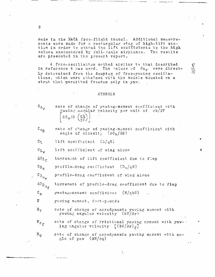
SYMBOLS
'n rate of change of yawing-moment coefficient with yawing angular velocity per unit of rh/2V
ÖCn/d (^-' \
27 J
P wn.
C»o
&0 WD,
IT
N,
'*
rate of change of ya. wing-moment coefficient v/ith angle of sideslip (3Cn/dß)
lift Cooificient (L/qS)
lift coefficient of wing alone
increment of lift coefficient due to flap
profile-drag coefficient (D0/q_S)
profile-drag coefficient of wing alone
increment of profile-drag coefficient due to flap
yawing-moment coefficient (I/GDS)
yawing moment, foot-pounds
rate of change of aerodynamic yawing moment with yawing angular velocity (dlT/dr)
rate of change of frictional yawing moment with yaw- ing angular velocity [(BK/3r)*]
rate of change of aerodynamic yawing moment with an- gle of yaw (dN/d\j;)
fr- CD to
I
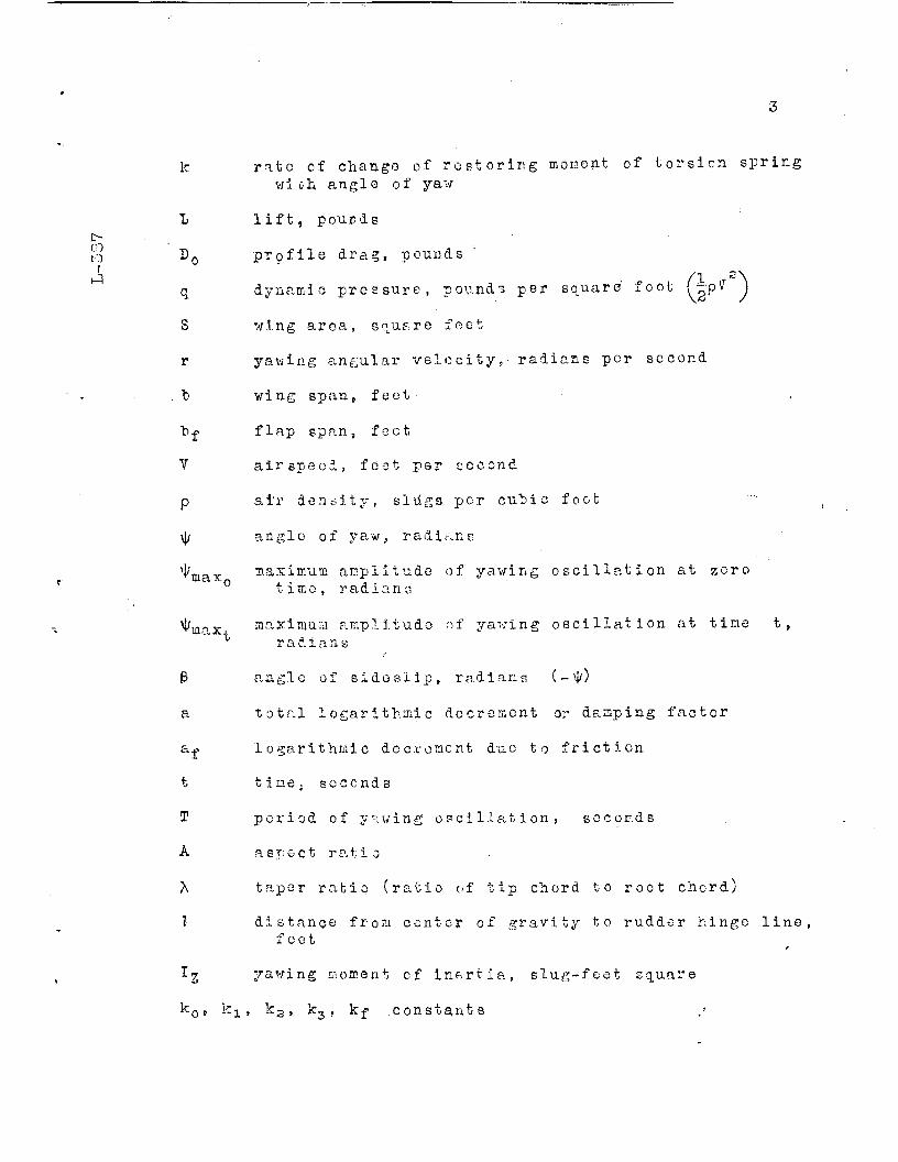
k
L
Do
S
r
o
V
P
rate of change of restoring moment of torsion spring with angle of yaw
max,
*ifla:
t
T
A
A
I
K)
lift, pounds
profile drag, pounds
dynamic pressure, pounds per square foot
wing area, square feet
yawing angular velocity,- radians per second
wing span, feet
flap span, feot
airspeed, foot per second
air density, slugs per cuhie foot
angle of yaw, radians
maximum amplitude of yawing oscillation at zero time, radians
maximum amplitude of yawing oscillation at time t, radians
angle of sideslip, radians (- \|/)
total logarithmic decrement or damping factor
logarithmic decrement due to friction
time; seconds
period of yawing oscillation, seconds
aspect ratio
taper ratio (ratio of tip chord to root chord)
distance from center of gravity to rudder hinge line, feet
yawing moment cf inertia, slug-feet square
k0, kjL , k3, k3. kf constants
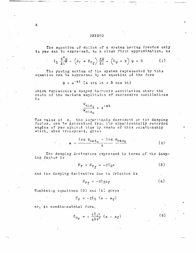
METHOD
The equation of motion of a system hevlng freedom only in yaw can 'be expressed, to a close first approximation, as
'* $'("* • "O !r ^ (** •k) * - ° (l1
The yawing motion of the system represented by this equation can "be expressed by an equation of the form
\\i = e"afc (A sin bt + B cos "bt)
which represents a damped harmonic oscillation where the ratio of the maximum amplitudes of successive oscillations la
'max* ~at •T- - _ e
*max0
The value of a, the logarithmic decrement or the damping factor, can te determined fror:, the experimentally recorded angles of yaw against time by. means of this relationship which t when trp.nspo so.4s gives
!og \|/mflir - log v a =3 -—-
iuaxn *"J Traast / \
° ~%- (2)
The damping derivative expressed in terms of the damp- ing factor is
Kr + Nrf - -ßlga (3)
and the damping derivative due to friction is
>rr^, = -2lZaf (4)
Combining equations (3) and (4) gives
lTr = ~2l% (a - a.f)
or, in nondimonsiohal form,
Cn „ „:Ü4 (a _ ftf) (5)
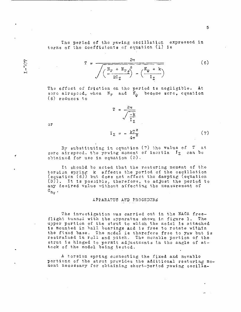
The period of the yawing oscillation expressed in terms of the coefficients of equation (l) is
CO
i l-H
T = 2TT
/ Nr + U
21. l£) . (5LÜ)
(6)
The effect of friction on the period is negligible. At zsro airspeed, when Nr and IT. (6) reduces to
"become zero, equation
T =
or
3TT
4TT;
(7)
3y substituting in equation (?) the value of zero airspeed, the yawing moment of inertia I obtained for use in equation (5).
nr
can at
be
It should he noted that the restoring moment of the torsion spring k affects the period of the oscillation (equation (6)} hut does not affect the damping (equation (3)) any °nr-'
It is possible, therefore, to adjust the period to .esired value without affecting the measurement of
APPARATUS AND PR0CEDUB3
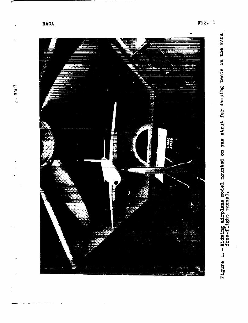
The investigation was carried out in the SAC A free- flight tunnel with the apparatus shown in figure 1. The upper portion of the strut to which the model is attached is mounted in ball bearings and is free to rotate within the fixed base. The model is therefore free to yaw but is restrained in roll and pitch. The movable portion of the strut is hinged to permit adjustments in the angle of at- tack of the model being tested.
A torsion spring connecting the fixed and movable portions of the strut provides the additional restoring mo- ment necessary for obtaining short-period yawing oscilla-
tions. It is important that the period of the ' oscilla- tions be fairly short to injure a well-defined oscillation envelope and therefore to permit an accurate measurement of damping.
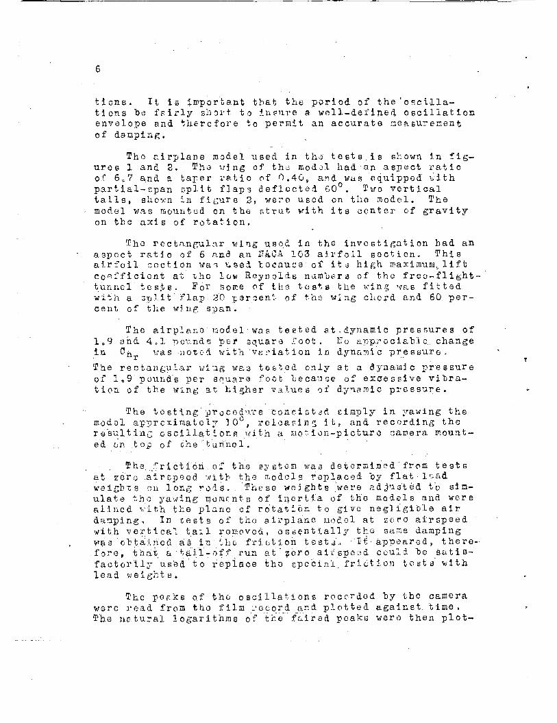
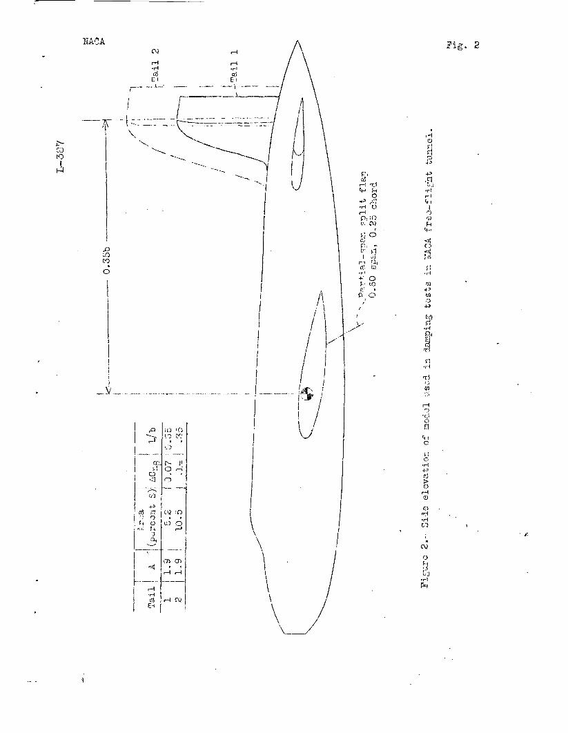
The airplane model used in ths tests, is shown in fig- ures 1 and 2. The wjng of the modol had an aspect ratio of 6fe7 and a taper ratio of 0.40, partial-span
and was split flaps deflected 60°. Two
equipped with vertical
tails, shown in figure 2, were usod on the model. The model was mounted on the strut with its center of gravity on the axis of rotation.
Tho rectangular wing usod in the investigation had an aspect ratio of 6 and an !T4CA 103 airfoil soot-ion. This airfoil section wa i used because of ita high maximum,, lift coefficient at the low Reynolds nam^era of the freo-flight- tunnel' tests. For some of the tests the wing was fitted with a split * i lap- 20 percent of tho wing chord and 60. per- cent, of the wing span.
The airplane model was tested at-dynamic pressures of 1 „ 9 and 4,1 pounds t>e_r square ooi 11 < appreciable, change in C n. was noted with variation in dynamic pressure
The rectangular wing was tested only at a dynamic pressure of 1.9'pound's per scuara foot "because of excessive vibra- tion of the wing at higher values of dynamic pressure.
The testing procedure consisted simply in yawing the model approximately 10°, reloading it, and recording the resulting oscillations with a mot. ion-picture camera mount- ed on .top of ehe tunnel.
The. .frie at.zero air op weights on lo ulate the yaw alined v it h t damping. In with vertical 1 was obtained as fore, 'that; "a tj factorlly used lead weights.
ti
rig in he ce
oh of the system was determined' d with the models replaced "by fl rods. . These weights were ad jus'
g moments of inertia of the mode plane of rotation to give negli sts of the airplane model at zer ail removed, essentially the sam in the friction test*;. It appe il-off run at "zero "airspeed coul to replace tho special, friction
fr<Mü tests at lead ted t'o sim- ls and were gible air o airspeed e damping aredj there- d be sati s- t e s t s with
The peaks of the oscillations roccrded by the camera were read from the film record and plotted against time. The natural logarithms of the" faired peaks were then plot-

CO cO 1
1-3
ted against time and the elopes of the resulting straight lino 9 were graphical representations of the logarithmic decrements a and aT.s The numerical values for a and a£ were determined from the slopes "by equation (2) and these values were substituted In equation (5) to obtain 0nr.
Lift and drag coefficients and yawing-moment coeffi- cients due to sideslip were determined "by tests on the six-component "balance in the tunnel for use in correlat- ing the measured values of Qn , with the theoretical de- rivatives«
THEORETICAL DAMPING D3RIVATITP-S
The value of Crj , for a complete airplane may be as- sumed to be made up of directly additive contributions of the vertical tail, wing, and fuselage, if interference ef- fect B arc neglected; that is,
Cnr - ^rUaiX} + A°ur(wing) + A°nr( fuselage)
It can be. shown that the contribution of the vertical tail. Is
n.r(tall)
lor a wing without flaps
^ i. Ar b rß(tail)
(S)
AC TJ / .. v = K0C3o + KJCL"
V (, '''Ixt g) 0 J'
Simple integration for K0 yields
.2 4- 2A/ iv Q = — U ,Ou (9)
Values for %x are given in figure 13 of reference 2, which may be represented by the equation
Kj. - -0.031 (l _ A - 6 3 ^ 13 2,5 J
The value -0.031 is for a rectangular wing of aspect
(10)
ratio 6.0. G-lauert, in reference 1, gives a value of -0.024 for tiiis condition,
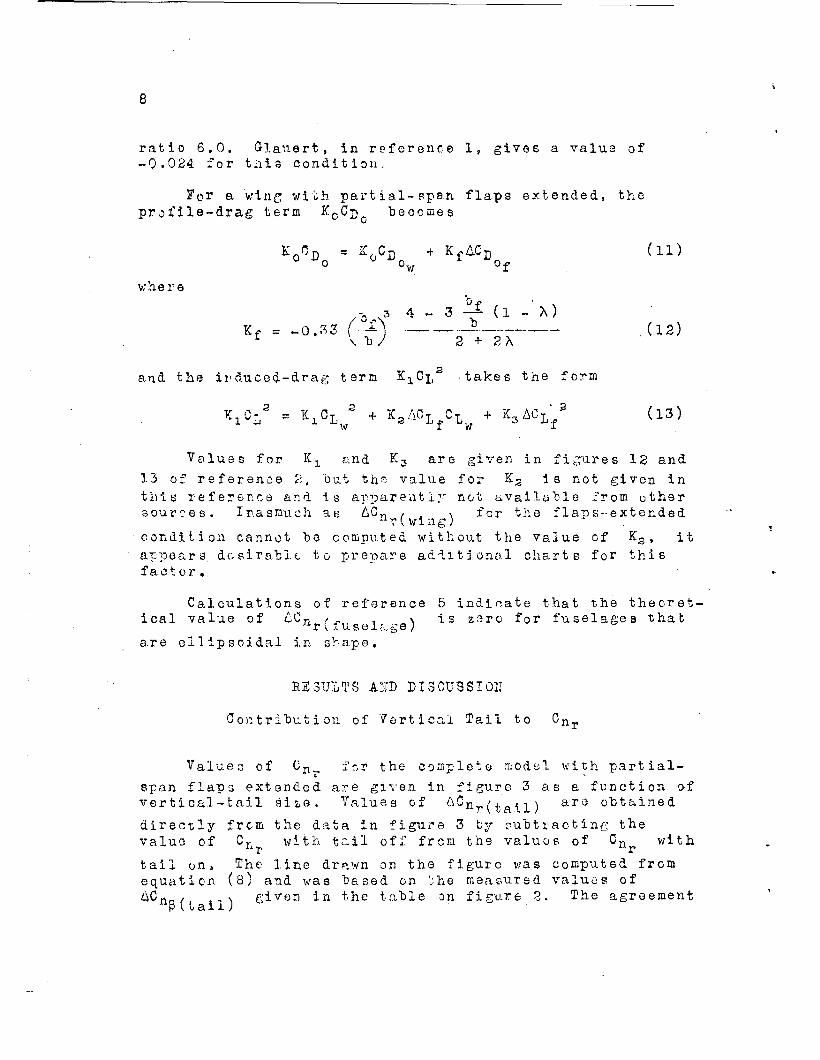
For a wine with partial-span flaps extended, the profile-drag term KcCj) becomes
KoCD„ = KoCD, + Kf^C'D(
where
K f = -0.33 (A
'w
3 4 - 3 -Ml - >0 0.~\ \,
\ "b / 3 + 2 A
and the induced-drag term ^-x^L takes the form
(11)
(12)
(13)
Values for Kx and K3 are given in figures 12 and 13 of reference 2, but the value for K3 is not given in this reference and is apparently not available from other sources. Inasmuch ae AC- , x for the flaps-extended
condition cannot ho computed without the value of K2, it appears desirable, to prepare additional charts for this factor.
Calculations of reference 5 indicate that the theoret- ical value of OCJI / „ , \ is zero for fuselages that J1r '\ fuselage) are ellipsoidal in shape.
RESULTS A1TD DISCUS SI Oil
Contribution of Vertical Tail to Cnr
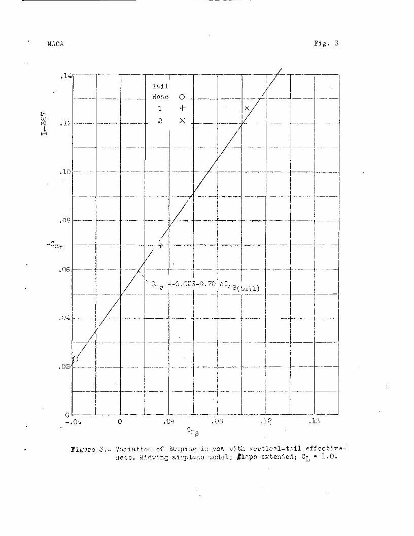
Values of ün_ for the complete model with partial- span flaps extended are given in figure 3 as a function of vertical-tail siae. Values of ^nWtail) ar3 obtained
directly from the data in figure 3 by subtracting the value of with tail off from the values of vn Cn with r tail on» The line drawn on the figure was computed from equation (8) and was based on the measured values of ACn ß(tail)
given in the table on figure 2. The agreement
co to I
between the test points and this computed line is an indi- cation that the contribution of the vertical tail to Cnr
for a midwing airplane can be computed with reasonable ac- curacy from the theoretical relation given in equation (8). For high- or low-wing airplanes a correction factor might be necessary for this relation because the sidewash at the tail, which varies with wing position, causes dif- ferent changes in AC,,, . and ACn . . . ng(tail) nr(tail)
Contribution of Fuselage to Cn
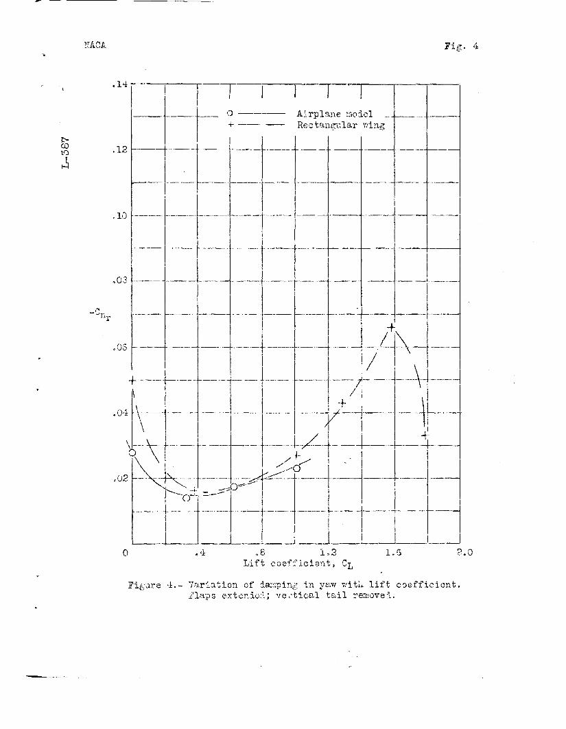
The data of figure 4 show the variation of Cnr with
lift coefficient for the fuselage-wing combination and for the rectangular wing with partial-span flaps extended. The value of Cnr for the fuselage and wing varied from
-0,014 to -0,028 over the lift range covered in the air- plane model tests.
A comparison of the Cn values for the fuselage-
wing combination with the values for the rectangular wing with flaps extended (fig. 4) indicates that the fuselage had a negligible effect on C-n . Although it appears from
a direct comparison cf the data that the fuselage slight- ly reduced Cn , this apparent reduction was probably-
caused by the difference in plan form and by the greater profile drag of the rectangular wing. Other recent tests, the results of which are 'unpublished, have indicated val- ues of AC„ , , ranging from -0.003 to -0.006. It
r(fuselage) appears, therefore, that the fuselage contribution to C
is normally small enough to be neglected. n.
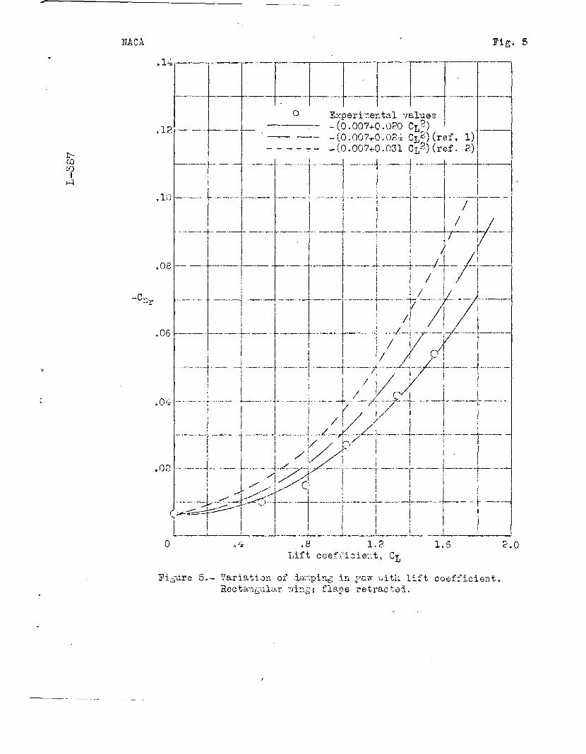
Contribution of Wing to
Variation of ACn , . N with lift coefficient.- The v\. wing; data of figure 5 show that ACn , . v for the wing with XJr(wingj flaps retracted varied as the square of the lift coeffi- cient, as predicted by theory, but that the value of Kx was smaller than the value predicted by either reference 1 or reference 2. The experimentally determined value of Kx for the rectangular wing was -0.020; whereas reference 1 predicted a value of -0.024 and reference 2, a value of
10
-0.031. It appears that the value of -0.031 given "by ref- erence 2 and used in equation (iO) Is too large and should be replaced "by -0.020."
The variation of Cri with lift coefficient for the 'T
wing with partial-apan flaps extended (f:l?. 4) differed from the variation with flaps retracted in that the mini- mam value of Cn was obtained at a small positive lift
coefficient rather than at zero lift, This result, which is also indicated by equation (j3)t is due to the fact that at zero lift the center flapped section is developing positive lift, the tip section is developing negative lift, and both are contributing to Cn Inasmuch as no calcu- lated value for the constant Kz was available, no corre- lation of the theoretical and experimental variation of
'nr(wing) flaps-extended condition
ACr, , . N with lift coefficient could be made for the
Variation of AC Muin^ w ith profile drag.- The
value o: C n, for the w*ng with flaps retracted at zero
lift was about -0.007, as shown in figure 5. The profile- drag coefficient Cp for the wing, as measured on the
balance in the tunnel for the same condition, was 0.024.
From the t;e two values, K0 is found to be ~^"T^7 or
-0.29. Equation {9) yields 0,33 as the theoretical value for K„ for a rectangular wing. It .ppears that the cal- u — — -
culated and the experimentally determined values of K( are in fairly good agreement.
With the partial-span flaps deflected on the rectangu- lar wing, the value of Cn clue to profile drag can be ob- clue to profile drag car
at the lift coefficien tained from the value of Cn given by the flap. For the wing tested, the flap gave an increment of lift coefficient of 0.60, From figure 4 at a lift coefficient of 0,60 the value of Cnr was -0.017. Combining equations (ll) and (13) and eliminating term3 containing
w because C^ = 0 at = 0.60, giv«
C» -4
Cn, = KoCI> + KfACD0 + K^L/ °w °f *
11
The value KQ^'D was -0-007 from the wing-alone test;
c- C.0 to
I Hi
'w 4'CT) was 0.080 fr om fores tests; K.» was -0.072 from
* Ojj L
equation (12); and K3 was -0.0092 from reference 2. Then, for a value of ACx, of 0,60,
r 2 0- -r- -0,007 + (-0.072x0.030) + \ -0 . 009 3* ( 0 . 60 ) r ' L
= -0.007 -0,006 -0.003
- -0.016
This result is in pood a^reem^nt with the measured value of -0.017. The magnitude of all.of these factors is small, however, compared vith the contribution of the tail surface.
Determination of Cn for Complete Model
The following empirical formula, which was derived from test results, should give a fair approximation of the value of Cn for a conventional nidwing airplane;
0.lr n ~f 2~A0 \ /'2+3/\> A A-b 1«X\ •- - • v -» -Kuuli " [°-3- Vst; CB
O + °-020 V1 " T3- - 2% Vj
COttCIUD'ü'G EEHAP'Sö
The free-oscillation method of determining damping in yaw is considered very satisfactory in that it provided reasonably accurate results quickly and easily. The follow- ing conclusions were dra.m from the results of the free- oscillabion tests of the rcidwing airplane model and the rec- tangular wing models
1, The experimental values fo•'•.'- the yawing moment due to yawing contributed "by the vertical tail were in good agreement with the calculated values.
2e The values of the yawing moment due to yawing contributed "by the wing varied as the square of the lift coefficient "bit were lower than those predicted "by theory.
12
3, The value of the yawing moment due to "yawing con- tributed "by the profile drag of the wing was approximately the same as the theoretical value.
4, The contribution of the fuselage to the yawing moment due to yawing was negligible compared with the value for the complete model.
5,, 1'he test results indicated that a fair approxima- tion ef the value cf the yawing moment due to yawing for a conventional midwing airplane could be obtained from an empirical formula.
Iiangley Memorial Aeronautical Laboratory, National Advisory Committee for Aeronautic:
Langley field, Va.
REFERENCES
1» Glauert, H.j Calculation of the Rotary Derivatives Due to Yawing for a Monoplane Wing, R. & H, No. 366, 3ritish A.R.C., 1933.
2, Pearson, Henry A.e and Jones, Robert T.j Theoretical Stability and Control Characteristics of Wings with Various Amounts of Taper and Twist. Rep. No, 635, NACA, 1938,
3, Zimmerman, Charles H.r- An Analysis of Lateral Stabil- ity in Power-Off Flight with Charts for Use in De- sign. Rep. Ho- 599, NACA , 1937,
T) ramvell, F . H., and Reif, E. F , t Experiments on Models of Complete Aeroplanes. Part IV - Determination of the Pitching Moment Due to Pitching for a Model Bi- plane at Various Inclinations to the Wind. R. & M. No. Ill, British A.C,A ., 1914.
5. Kunk, Max M.s Fundamentals of Fluid Dynamics for Air- craft Designers* The Ronald Press Co., 1929,
NACA Fig. 1
c- 0° CO
i
<
©
•P
09 +» CD q> •p
9 •H
I 4» CB
d o
«d -P
H q> •d o •
© © d si H-P
fr«.
•H MH Ö«H •H J 5 • •d © •H M
H

NACA
X
to
,0 10 to
„V._ __
Fig. 2
r-l O r!
r-l
1 n i)
O <3j
-I' 0» Q
tin n •H
fi •H
CO
o a
r. c •H
> G)
<U
Q >H •H
o f.)
•H

NACA Fig. 3
,i±r——r
co to .1? I
.10
.08
~C *r
,04
.02-
/ /"
1
/
o1- -.04
/
I Tail
ifone O .. _
1 + a X _
-
.Z. /
'
—„.».—
=-0.023-0.70 &:
.04
Pi^-ure 3.- Variation of .lamping in yaw wjta vertical-tail effoctive- nesä. Mid'.ving airplano model; £i'-ps extended; C^ = 1.0.

I-IACA Pig. 4
co to
Lift coefficient, Cj,
Figure 4.- Variation of damping in yaw witli lift coefficient. ..flaps extended; vertical tail removed.

NACA Pig. 5
,14
00 LO
I 1-3
,12
o Experimental values -(0.007+0.0P0 CL3) -(0.007+0.02-1 CL2)(ref, 1) -(0.007+0.031 CL2)(ref. 2)
.8 l.g Lift coefficient, C^
Figure 5.- Variation of damping in jraw vätli lift coefficient, Rectangular v/in^j flaps retracted.
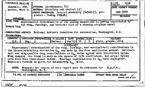
: Campbell, J?p. I Kathew, Ward 0. I
DIVISION: Aerodynamic» (s) SfCTlONi Stability and Control (1) CBOSS REFERENCES: Lateral stability (5JM9.7); Ur- planes - Yawing (081)98)
W0= 7932 OMG: AGENCY NUMBEQ
ARB-3F28
AUTHORS) AMEO-TlTlEi Experimentel daterraination of tha y.-wing moment due to yawing contributed by
the wing, fuselage, and vertical tail of a midwing eirplene model FOSG-N. TTIU,
OBKKNATING AGENCY. ; TRANSLATION.
Rational Advisory Committee for Aeronautioe, Washington, D.C.
ßTÖTOACT ' Experimental determination of the wing, fuselage, and vertical-teil contributions to
the lateral-stability derivative C„ was made by tha free oscillation method. Vorticel- tail ond wing-profile drag contributions to C- value egreed with- theoretical value. Hing damping uaa found to vary as the oquare of lift coefficient, but ectual values wero lese then theoretical values. Fuselage contributions to Cnr were negligible, finpirioel formula is given for determining C« value.
HOTBi Requests for copiee of thie report must be eddressed to» H.A.C.A., Washington, D. C.
T-Z KQ, AD MATESa COMMAND •TSQTJI ECKNiCAL I NDBt WRIGHT FIEIO, OHIO, USAAF j).
RiJAV JfVtfL