p: sscguidevt finaledited finalchapter 01c.ymcdn.com/sites/ · pdf filethe sudden movement...
TRANSCRIPT

1-1
1FUNDAMENTALS
James Robert Harris, P.E., Ph.D.
In introducing their well-known text, Fundamentals of Earthquake Engineering, Newmark andRosenblueth (1971) comment:
In dealing with earthquakes, we must contend with appreciable probabilities that failure will occurin the near future. Otherwise, all the wealth of the world would prove insufficient to fill ourneeds: the most modest structures would be fortresses. We must also face uncertainty on a largescale, for it is our task to design engineering systems – about whose pertinent properties we knowlittle – to resist future earthquakes and tidal waves – about whose characteristics we know evenless. . . . In a way, earthquake engineering is a cartoon. . . . Earthquake effects on structuressystematically bring out the mistakes made in design and construction, even the minutest mistakes.
Several points essential to an understanding of the theories and practices of earthquake-resistant designbear restating:
1. Ordinarily, a large earthquake produces the most severe loading that a building is expected to survive. The probability that failure will occur is very real and is greater than for other loading phenomena. Also, in the case of earthquakes, the definition of failure is altered to permit certain types of behaviorand damage that are considered unacceptable in relation to the effects of other phenomena.
2. The levels of uncertainty are much greater than those encountered in the design of structures to resistother phenomena. This applies both to knowledge of the loading function and to the resistanceproperties of the materials, members, and systems.
3. The details of construction are very important because flaws of no apparent consequence often willcause systematic and unacceptable damage simply because the earthquake loading is so severe and anextended range of behavior is permitted.
The remainder of this chapter is devoted to a very abbreviated discussion of fundamentals that reflect theconcepts on which earthquake-resistant design are based. When appropriate, important aspects of theNEHRP Recommended Provisions for Seismic Regulations for New Buildings and Other Structures arementioned and reference is made to particularly relevant portions of the document. Note that through2000, the NEHRP Recommended Provisions has been composed of two volumes of text and a separate setof maps. Part 1 (referred to herein as the Provisions) contains the actual requirements and Part 2 (referredto herein as the Commentary) provides a discussion of various aspects of the requirements.
Although the set of design examples is based on the 2000 Provisions, it is annotated to reflect changesmade to the 2003 Provisions. Annotations within brackets, [ ], indicate both organizational changes (as aresult of a reformat of all of the chapters of the 2003 Provisions) and substantive technical changes to the2003 Provisions and its primary reference documents. While the general concepts of the changes are

FEMA 451, NEHRP Recommended Provisions: Design Examples
1-2
described, the design examples and calculations in this book have not been revised to reflect the changesto the 2003 Provisions. Where related to the discussion in this chapter, significant changes to the 2003Provisions and primary reference documents are noted. However, some minor changes to the 2003Provisions and the reference documents may not be noted.
1.1 EARTHQUAKE PHENOMENA
According to the most widely held scientific belief, most earthquakes occur when two segments of theearth’s crust suddenly move in relation to one another. The surface along which movement occurs isknown as a fault. The sudden movement releases strain energy and causes seismic waves to propagatethrough the crust surrounding the fault. These waves cause the surface of the ground to shake violently,and it is this ground shaking that is the principal concern of structural engineering to resist earthquakes.
Earthquakes have many effects in addition to ground shaking. For various reasons, the other effects generally are not major considerations in the design of buildings and similar structures. For example,seismic sea waves or tsunamis can cause very forceful flood waves in coastal regions, and seiches (long-period sloshing) in lakes and inland seas can have similar effects along shorelines. These are outside thescope of the Provisions. This is not to say, however, that they should not be considered during siteexploration and analysis. Designing structures to resist such hydrodynamic forces is a very specializedtopic, and it is common to avoid constructing buildings and similar structures where such phenomena arelikely to occur. Long-period sloshing of the liquid contents of tanks is addressed by the Provisions.
Abrupt ground displacements occur where a fault intersects the ground surface. (This commonly occursin California earthquakes but apparently did not occur in the historic Charleston, South Carolina,earthquake or the very large New Madrid, Missouri, earthquakes of the nineteenth century.) Mass soilfailures such as landslides, liquefaction, and gross settlement are the result of ground shaking onsusceptible soil formations. Once again, design for such events is specialized, and it is common to locatestructures so that mass soil failures and fault breakage are of no major consequence to their performance. Modification of soil properties to protect against liquefaction is one important exception; large portions ofa few metropolitan areas with the potential for significant ground shaking are susceptible to liquefaction. Lifelines that cross faults require special design beyond the scope of the Provisions. The structural loadsspecified in the Provisions are based solely on ground shaking; they do not provide for ground failure. The Commentary includes a method for prediction of susceptibility to liquefaction as well as generalguidelines for locating potential fault rupture zones.
Nearly all large earthquakes are tectonic in origin – that is, they are associated with movements of andstrains in large segments of the earth’s crust, called plates, and virtually all such earthquakes occur at ornear the boundaries of these plates. This is the case with earthquakes in the far western portion of theUnited States where two very large plates, the North American continent and the Pacific basin, cometogether. In the central and eastern United States, however, earthquakes are not associated with such aplate boundary and their causes are not as completely understood. This factor, combined with the smalleramount of data about central and eastern earthquakes (because of their infrequency), means that theuncertainty associated with earthquake loadings is higher in the central and eastern portions of the nationthan in the West. Even in the West, the uncertainty (when considered as a fraction of the predicted level)about the hazard level is probably greater in areas where the mapped hazard is low than in areas where themapped hazard is high.
The amplitude of earthquake ground shaking diminishes with distance from the source, and the rate ofattenuation is less for lower frequencies of motion than for higher frequencies. This effect is captured, toan extent, by the fact that the Provisions uses two sets of maps define the hazard of seismic groundshaking – one is pertinent for higher frequency motion (the SS maps) and the other for lower frequencies(the S1 maps). There is evidence that extreme motions near the fault in certain types of large earthquakes
Chapter 1, Fundamentals
1-3
are not captured by the maps, but interim adjustments to design requirements for such a possibility areincluded in the Provisions.
Two basic data sources are used in establishing the likelihood of earthquake ground shaking, orseismicity, at a given location. The first is the historical record of earthquake effects and the second is thegeological record of earthquake effects. Given the infrequency of major earthquakes, there is no place inthe United States where the historical record is long enough to be used as a reliable basis for earthquakeprediction – certainly not as reliable as with other phenomena such as wind and snow. Even on theeastern seaboard, the historical record is too short to justify sole reliance on the historical record. Thus,the geological record is essential. Such data require very careful interpretation, but they are used widelyto improve knowledge of seismicity. Geological data have been developed for many locations as part ofthe nuclear power plant design process. On the whole, there are more geological data available for the farwestern United States than for other regions of the country. Both sets of data have been taken intoaccount in the Provisions seismic hazard maps. Ground shaking, however, is known to vary considerablyover small distances and the Provisions maps do not attempt to capture all such local variations(commonly called microzoning).
The Commentary provides a more thorough discussion of the development of the maps, their probabilisticbasis, the necessarily crude lumping of parameters, and other related issues. In particular, note thedescription of the newest generation of maps introduced in 1997 and their close relationship to thedevelopment of a new design criterion. There are extended discussions of these issues in the appendicesto the Commentary. Prior to its 1997 edition, the basis of the Provisions was to “provide life safety at thedesign earthquake motion,” which was defined as having a 10 percent probability of being exceeded in a50-year reference period. As of the 1997 edition, the basis became to “avoid structural collapse at themaximum considered earthquake (MCE) ground motion,” which is defined as having a 2 percentprobability of being exceeded in a 50-year reference period. In the long term, the change from life safetyto structural collapse prevention as the limit state will create significant changes in procedures for designanalysis. In the present interim, the ground motions for use with present design procedures are simplytaken as being two-thirds of the MCE ground motions.
1.2 STRUCTURAL RESPONSE TO GROUND SHAKING
The first important difference between structural response to an earthquake and response to most otherloadings is that the earthquake response is dynamic, not static. For most structures, even the response towind is essentially static. Forces within the structure are due almost entirely to the pressure loading ratherthan the acceleration of the mass of the structure. But with earthquake ground shaking, the abovegroundportion of a structure is not subjected to any applied force. The stresses and strains within thesuperstructure are created entirely by its dynamic response to the movement of its base, the ground. Eventhough the most used design procedure resorts to the use of a concept called the equivalent static force foractual calculations, some knowledge of the theory of vibrations of structures is essential.
1.2.1 Response Spectra
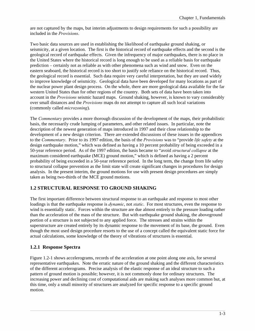
Figure 1.2-1 shows accelerograms, records of the acceleration at one point along one axis, for severalrepresentative earthquakes. Note the erratic nature of the ground shaking and the different characteristicsof the different accelerograms. Precise analysis of the elastic response of an ideal structure to such apattern of ground motion is possible; however, it is not commonly done for ordinary structures. Theincreasing power and declining cost of computational aids are making such analyses more common but, atthis time, only a small minority of structures are analyzed for specific response to a specific groundmotion.
FEMA 451, NEHRP Recommended Provisions: Design Examples
1-4
El Centro 1940
Imperial 6 (Hudson) 1979
Landers(Joshua Tree) 1992
Kern Taft 1952
Kobe 1995
Loma Prieta(Oakland Wharf) 1989
Mexico City 1985
Morgan Hill (Gilroy) 1984
North Palm Springs 1986
Northridge(Sylmar 90°) 1994
San Fernando (Pacoima Dam) 1971
San Fernando (Orion Blvd.) 1971
Northridge(Sylmar 360°) 1994
Tabas 1978
Figure 1.2-1 Earthquake ground acceleration in epicentral regions (all accelerograms are plotted to thesame scale for time and acceleration). Great earthquakes extend for much longer periods of time.
Figure 1.2-2 shows further detail developed from an accelerogram. Part (a) shows the groundacceleration along with the ground velocity and ground displacement derived from it. Part (b) shows the

Chapter 1, Fundamentals
1-5
20
0
-2030
0
-30250
0
-250
Acc
eler
atio
n,cm
\s\s
Vel
ocity
,cm
\sD
ispl
acem
ent,
cm
0 10 20 30 40
Time, s
(a) Ground acceleration, velocity, and displacement
030
0
10 20 30 40
-3070
0
-70500
0
-500
Dis
plac
emen
t,cm
Vel
ocity
,cm
\sA
ccel
erat
ion,
cm\s
\s
Time, s
(b) Roof acceleration, velocity, and displacement
acceleration, velocity, and displacement for the same event at the roof of the building located where theground motion was recorded. Note that the peak values are larger in the diagrams of Figure 1.2-2(b) (thevertical scales are different). This increase in response of the structure at the roof level over the motion ofthe ground itself is known as dynamic amplification. It depends very much on the vibrationalcharacteristics of the structure and the characteristic frequencies of the ground shaking at the site.
Figure 1.2-2 Holiday Inn ground and building roof motion during the M6.4 1971 San Fernandoearthquake: (a) north-south ground acceleration, velocity, and displacement and (b) north-south roofacceleration, velocity, and displacement (Housner and Jennings 1982). Note that the vertical scale of (b) isdifferent from (a). The Holiday Inn, a 7-story, reinforced concrete frame building, was approximately 5miles from the closest portion of the causative fault. The recorded building motions enabled an analysis tobe made of the stresses and strains in the structure during the earthquake.
In design, the response of a specific structure to an earthquake is ordinarily predicted from a designresponse spectrum such as is specified in the Provisions. The first step in creating a design responsespectrum is to determine the maximum response of a given structure to a specific ground motion (seeFigure 1.2-2). The underlying theory is based entirely on the response of a single-degree-of-freedomoscillator such as a simple one-story frame with the mass concentrated at the roof. The vibrationalcharacteristics of such a simple oscillator may be reduced to two: the natural frequency and the amountof damping. By recalculating the record of response versus time to a specific ground motion for a widerange of natural frequencies and for each of a set of common amounts of damping, the family of responsespectra for one ground motion may be determined. It is simply the plot of the maximum value ofresponse for each combination of frequency and damping.
Figure 1.2-3 shows such a result for the ground motion of Figure 1.2-2(a) and illustrates that the erraticnature of ground shaking leads to a response that is very erratic in that a slight change in the naturalperiod of vibration brings about a very large change in response. Different earthquake ground motionslead to response spectra with peaks and valleys at different points with respect to the natural frequency. Thus, computing response spectra for several different ground motions and then averaging them, based onsome normalization for different amplitudes of shaking, will lead to a smoother set of spectra. Suchsmoothed spectra are an important step in developing a design spectrum.

FEMA 451, NEHRP Recommended Provisions: Design Examples
1-6
Figure 1.2-3 Response spectrum of north-south ground acceleration (0, 0.02, 0.05, 0.10, 0.20 ofcritical damping) recorded at the Holiday Inn, approximately 5 miles from the causative fault inthe 1971 San Fernando earthquake (Housner and Jennings 1982).
Figure 1.2-4 is an example of an averaged spectrum. Note that the horizontal axes of Figures 1.2-3 and1.2-4 are different, one being for the known frequency (period) while the other is for the cyclic frequency. Cyclic frequency is the inverse of period; therefore, Figure 1.2-4 should be rotated about the line f = 1 tocompare it with Figure 1.2-3. Note that acceleration, velocity, or displacement may be obtained fromFigure 1.2-3 or 1.2-4 for a structure with known frequency (period) and damping.

Chapter 1, Fundamentals
1-7
Figure 1.2-4 Averaged spectrum (Newmark, Blume, and Kapur 1973). Mean and mean plus onestandard deviation acceleration, horizontal components (2.0 percent of critical damping). Reprinted with permission from the American Society of Civil Engineers.
Prior to the 1997 editions of the Provisions, the maps that characterized the ground shaking hazard wereplotted in terms of peak ground acceleration, and design response spectra were created using expressionsthat amplified (or de-amplified) the ground acceleration as a function of period and damping. With theintroduction of the MCE ground motions, this procedure changed. Now the maps present spectralresponse accelerations at two periods of vibration, 0.2 and 1.0 second, and the design response spectrumis computed more directly. This has removed a portion of the uncertainty in predicting responseaccelerations.
Few structures are so simple as to actually vibrate as a single-degree-of-freedom system. The principlesof dynamic modal analysis, however, allow a reasonable approximation of the maximum response of amulti-degree-of-freedom oscillator, such as a multistory building, if many specific conditions are met. The procedure involves dividing the total response into a number of natural modes, modeling each modeas an equivalent single-degree-of-freedom oscillator, determining the maximum response for each modefrom a single-degree-of-freedom response spectrum, and then estimating the maximum total response bystatistically summing the responses of the individual modes. The Provisions does not requireconsideration of all possible modes of vibration for most buildings because the contribution of the highermodes (higher frequencies) to the total response is relatively minor.
FEMA 451, NEHRP Recommended Provisions: Design Examples
1-8
The soil at a site has a significant effect on the characteristics of the ground motion and, therefore, on thestructure’s response. Especially at low amplitudes of motion and at longer periods of vibration, soft soilsamplify the motion at the surface with respect to bedrock motions. This amplification is diminishedsomewhat, especially at shorter periods as the amplitude of basic ground motion increases, due to yieldingin the soil. The Provisions accounts for this effect by providing amplifiers that are to be applied to the 0.2and 1.0 second spectral accelerations for various classes of soils. (The MCE ground motion maps aredrawn for sites on rock.) Thus, very different design response spectra are specified depending on the typeof soil(s) beneath the structure. The Commentary contains a thorough explanation of this feature.
1.2.2 Inelastic Response
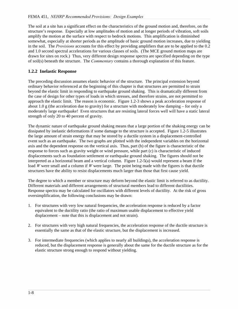
The preceding discussion assumes elastic behavior of the structure. The principal extension beyondordinary behavior referenced at the beginning of this chapter is that structures are permitted to strainbeyond the elastic limit in responding to earthquake ground shaking. This is dramatically different fromthe case of design for other types of loads in which stresses, and therefore strains, are not permitted toapproach the elastic limit. The reason is economic. Figure 1.2-3 shows a peak acceleration response ofabout 1.0 g (the acceleration due to gravity) for a structure with moderately low damping – for only amoderately large earthquake! Even structures that are resisting lateral forces well will have a static lateralstrength of only 20 to 40 percent of gravity.
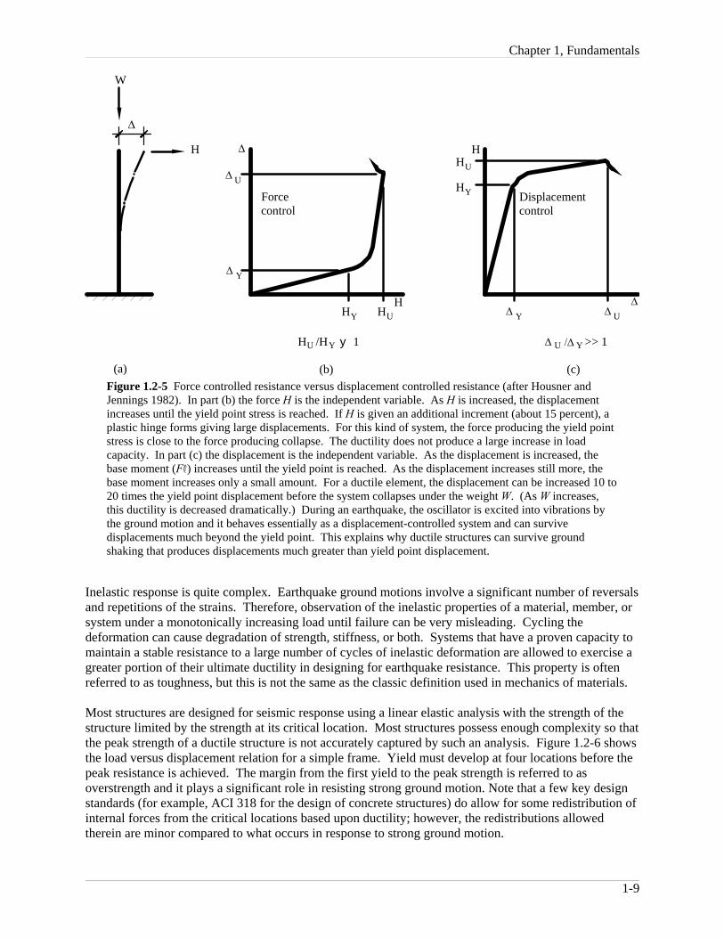
The dynamic nature of earthquake ground shaking means that a large portion of the shaking energy can bedissipated by inelastic deformations if some damage to the structure is accepted. Figure 1.2-5 illustratesthe large amount of strain energy that may be stored by a ductile system in a displacement-controlledevent such as an earthquake. The two graphs are plotted with the independent variables on the horizontalaxis and the dependent response on the vertical axis. Thus, part (b) of the figure is characteristic of theresponse to forces such as gravity weight or wind pressure, while part (c) is characteristic of induceddisplacements such as foundation settlement or earthquake ground shaking. The figures should not beinterpreted as a horizontal beam and a vertical column. Figure 1.2-5(a) would represent a beam if theload W were small and a column if W were large. The point being made with the figures is that ductilestructures have the ability to resist displacements much larger than those that first cause yield.
The degree to which a member or structure may deform beyond the elastic limit is referred to as ductility. Different materials and different arrangements of structural members lead to different ductilities. Response spectra may be calculated for oscillators with different levels of ductility. At the risk of grossoversimplification, the following conclusions may be drawn:
1. For structures with very low natural frequencies, the acceleration response is reduced by a factorequivalent to the ductility ratio (the ratio of maximum usable displacement to effective yielddisplacement – note that this is displacement and not strain).
2. For structures with very high natural frequencies, the acceleration response of the ductile structure isessentially the same as that of the elastic structure, but the displacement is increased.
3. For intermediate frequencies (which applies to nearly all buildings), the acceleration response isreduced, but the displacement response is generally about the same for the ductile structure as for theelastic structure strong enough to respond without yielding.
Chapter 1, Fundamentals
1-9
H
HH
Forcecontrol
Displacementcontrol
HY HU ∆ Y U∆
∆
∆
H /H y 1
(b)
U Y >> 1
(c)
U Y/∆∆
∆
(a)
W
HY
HU
∆ Y
U∆
Figure 1.2-5 Force controlled resistance versus displacement controlled resistance (after Housner andJennings 1982). In part (b) the force H is the independent variable. As H is increased, the displacementincreases until the yield point stress is reached. If H is given an additional increment (about 15 percent), aplastic hinge forms giving large displacements. For this kind of system, the force producing the yield pointstress is close to the force producing collapse. The ductility does not produce a large increase in loadcapacity. In part (c) the displacement is the independent variable. As the displacement is increased, thebase moment (FR) increases until the yield point is reached. As the displacement increases still more, thebase moment increases only a small amount. For a ductile element, the displacement can be increased 10 to20 times the yield point displacement before the system collapses under the weight W. (As W increases,this ductility is decreased dramatically.) During an earthquake, the oscillator is excited into vibrations bythe ground motion and it behaves essentially as a displacement-controlled system and can survivedisplacements much beyond the yield point. This explains why ductile structures can survive groundshaking that produces displacements much greater than yield point displacement.
Inelastic response is quite complex. Earthquake ground motions involve a significant number of reversalsand repetitions of the strains. Therefore, observation of the inelastic properties of a material, member, orsystem under a monotonically increasing load until failure can be very misleading. Cycling thedeformation can cause degradation of strength, stiffness, or both. Systems that have a proven capacity tomaintain a stable resistance to a large number of cycles of inelastic deformation are allowed to exercise agreater portion of their ultimate ductility in designing for earthquake resistance. This property is oftenreferred to as toughness, but this is not the same as the classic definition used in mechanics of materials.
Most structures are designed for seismic response using a linear elastic analysis with the strength of thestructure limited by the strength at its critical location. Most structures possess enough complexity so thatthe peak strength of a ductile structure is not accurately captured by such an analysis. Figure 1.2-6 showsthe load versus displacement relation for a simple frame. Yield must develop at four locations before thepeak resistance is achieved. The margin from the first yield to the peak strength is referred to asoverstrength and it plays a significant role in resisting strong ground motion. Note that a few key designstandards (for example, ACI 318 for the design of concrete structures) do allow for some redistribution ofinternal forces from the critical locations based upon ductility; however, the redistributions allowedtherein are minor compared to what occurs in response to strong ground motion.

FEMA 451, NEHRP Recommended Provisions: Design Examples
1-10
2 1
4 3
5 51010
H
δ
(a) Structures (b) H - δ curve
0 0.5 1 2 3 4 51.5 2.5 3.5 4.5
0
20
40
60
80
100
120
140
160
HY
HU
Figure 1.2-6 Initial yield load and failure load for a ductile portal frame. The margin from initialyield to failure (mechanism in this case) is known as overstrength.
To summarize, the characteristics important in determining a building’s seismic response are naturalfrequency, damping, ductility, stability of resistance under repeated reversals of inelastic deformation,and overstrength. The natural frequency is dependent on the mass and stiffness of the building. Usingthe Provisions, the designer calculates, or at least approximates, the natural period of vibration (theinverse of natural frequency). Damping, ductility, toughness, and overstrength depend primarily on thetype of building system, but not the building’s size or shape. Three coefficients – R, Cd, and Ω0 – areprovided to encompass damping, ductility, stability of resistance, and overstrength. R is intended to be aconservatively low estimate of the reduction of acceleration response in a ductile system from that for anelastic oscillator with a certain level of damping. It is used to compute a required strength. Computationsof displacement based upon ground motion reduced by the factor R will underestimate the actualdisplacements. Cd is intended to be a reasonable mean for the amplification necessary to convert theelastic displacement response computed for the reduced ground motion to actual displacements. Ω0 isintended to deliver a reasonably high estimate of the peak force that would develop in the structure. Setsof R, Cd, and Ω0 are specified in the Provisions for the most common structural materials and systems.
1.2.3 Building Materials
The following brief comments about building materials and systems are included as general guidelinesonly, not for specific application.
1.2.3.1 Wood
Timber structures nearly always resist earthquakes very well, even though wood is a brittle material as faras tension and flexure are concerned. It has some ductility in compression (generally monotonic), and itsstrength increases significantly for brief loadings, such as earthquake. Conventional timber structures(plywood or board sheathing on wood framing) possess much more ductility than the basic materialprimarily because the nails and other steel connection devices yield and the wood compresses against theconnector. These structures also possess a much higher degree of damping than the damping that isassumed in developing the basic design spectrum. Much of this damping is caused by slip at theconnections. The increased strength, connection ductility, and high damping combine to give timber

Chapter 1, Fundamentals
1-11
structures a large reduction from elastic response to design level. This large reduction should not be usedif the strength of the structure is actually controlled by bending or tension of the gross timber crosssections. The large reduction in acceleration combined with the light weight timber structures make themvery efficient with regard to earthquake ground shaking when they are properly connected. This isconfirmed by their generally good performance in earthquakes.
1.2.3.2 Steel
Steel is the most ductile of the common building materials. The moderate-to-large reduction from elasticresponse to design response allowed for steel structures is primarily a reflection of this ductility and thestability of the resistance of steel. Members subject to buckling (such as bracing) and connections subjectto brittle fracture (such as partial penetration welds under tension) are much less ductile and are addressedin the Provisions in various ways. Other defects, such as stress concentrations and flaws in welds, alsoaffect earthquake resistance as demonstrated in the Northridge earthquake. The basic and appliedresearch program that grew out of that demonstration has greatly increased knowledge of how to avoidlow ductility details in steel construction.
1.2.3.3 Reinforced Concrete
Reinforced concrete achieves ductility through careful limits on steel in tension and concrete incompression. Reinforced concrete beams with common proportions can possess ductility undermonotonic loading even greater than common steel beams, in which local buckling is usually a limitingfactor. Providing stability of the resistance to reversed inelastic strains, however, requires specialdetailing. Thus, there is a wide range of reduction factors from elastic response to design responsedepending on the detailing for stable and assured resistance. The Commentary and the commentary withthe ACI 318 standard for design of structural concrete explain how controlling premature shear failures inmembers and joints, buckling of compression bars, concrete compression failures (through confinementwith transverse reinforcement), the sequence of plastification, and other factors lead to larger reductionsfrom the elastic response.
1.2.3.4 Masonry
Masonry is a more diverse material than those mentioned above, but less is known about its inelasticresponse characteristics. For certain types of members (such as pure cantilever shear walls), reinforcedmasonry behaves in a fashion similar to reinforced concrete. The nature of the masonry construction,however, makes it difficult, if not impossible, to take some of the steps (e.g., confinement of compressionmembers) used with reinforced concrete to increase ductility and stability. Further, the discretedifferences between mortar and the masonry unit create additional failure phenomena. Thus, thereduction factors for reinforced masonry are not quite as large as those for reinforced concrete. Unreinforced masonry possesses little ductility or stability, except for rocking of masonry piers on a firmbase, and very little reduction from the elastic response is permitted.
1.2.3.5 Precast Concrete
Precast concrete obviously can behave quite similarly to reinforced concrete, but it also can behave quitedifferently. The connections between pieces of precast concrete commonly are not as strong as themembers being connected. Clever arrangements of connections can create systems in which yieldingunder earthquake motions occurs away from the connections, in which case the similarity to reinforcedconcrete is very real. Some carefully detailed connections also can mimic the behavior of reinforcedconcrete. Many common connection schemes, however, will not do so. Successful performance of suchsystems requires that the connections perform in a ductile manner. This requires some extra effort indesign, but it can deliver successful performance. As a point of reference, the most common wood

FEMA 451, NEHRP Recommended Provisions: Design Examples
1-12
seismic resisting systems perform well yet have connections (nails) that are significantly weaker than theconnected elements (structural wood panels). The Provisions includes guidance, some only for trial useand comment, for seismic design of precast structures.
1.2.3.6 Composite Steel and Concrete
Reinforced concrete is a composite material. In the context of the Provisions, composite is a termreserved for structures with elements consisting of structural steel and reinforced concrete acting in acomposite manner. These structures generally are an attempt to combine the most beneficial aspects ofeach material.
1.2.4 Building Systems
Three basic lateral-load-resisting elements – walls, braced frames, and unbraced frames (moment resistingframes) – are used to build a classification of structural types in the Provisions. Unbraced framesgenerally are allowed greater reductions from elastic response than walls and braced frames. In part, thisis because frames are more redundant, having several different locations with approximately the samestress levels, and common beam-column joints frequently exhibit an ability to maintain a stable responsethrough many cycles of reversed inelastic deformations. Systems using connection details that have notexhibited good ductility and toughness, such as unconfined concrete and the welded steel joint usedbefore the Northridge earthquake, are penalized with small reduction factors.
Connection details often make development of ductility difficult in braced frames, and buckling ofcompression members also limits their inelastic response. Eccentrically braced steel frames and newproportioning and detailing rules for concentrically braced frames have been developed to overcome theseshortcomings. [The 2003 Provisions include proportioning and detailing rules for buckling-restrainedbraced frames. This new system has the advantages of a special steel concentrically braced frame, butwith performance that is superior as brace buckling is prevented. Design provisions appear in 2003Provisions Sec. 8.6.] Walls that are not load bearing are allowed a greater reduction than walls that areload bearing. Redundancy is one reason; another is that axial compression generally reduces the flexuralductility of concrete and masonry elements (although small amounts of axial compression usuallyimprove the performance of materials weak in tension, such as masonry and concrete). Systems thatcombine different types of elements are generally allowed greater reductions from elastic responsebecause of redundancy.
Redundancy is frequently cited as a desirable attribute for seismic resistance. A quantitative measure ofredundance has been introduced in recent editions of the Provisions in an attempt to prevent use of largereductions from elastic response in structures that actually possess very little redundancy. As with manynew empirical measures, it is not universally accepted and is likely to change in the future. [In the 2003Provisions, a radical change was made to the requirements related to redundancy. Only two values of theredundancy factor, ρ, are defined: 1.0 and 1.3. Assignment of a value for ρ is based on explicitconsideration of the consequence of failure of a single element of the seismic-force-resisting system. Asimple, deemed-to-comply exception is provided for certain structures.]
1.3 ENGINEERING PHILOSOPHY

Chapter 1, Fundamentals
1-13
The Provisions, under “Purpose,” states:
The design earthquake ground motion levels specified herein could result in both structuraland nonstructural damage. For most structures designed and constructed according to theProvisions, structural damage from the design earthquake ground motion would be repairablealthough perhaps not economically so. For essential facilities, it is expected that the damagefrom the design earthquake ground motion would not be so severe as to preclude continuedoccupancy and function of the facility. . . . For ground motions larger than the design levels,the intent of the Provisions is that there be low likelihood of structural collapse.
The two points to be emphasized are that damage is to be expected when an earthquake (equivalent to thedesign earthquake) occurs and that the probability of collapse is not zero. The design earthquake groundmotion level mentioned is two-thirds of the MCE ground motion.
The basic structural criteria are strength, stability, and distortion. The yield-level strength provided mustbe at least that required by the design spectrum (which is reduced from the elastic spectrum as describedpreviously). Structural elements that cannot be expected to perform in a ductile manner are to havestrengths greater than those required by the Ω0 amplifier on the design spectral response. The stabilitycriterion is imposed by amplifying the effects of lateral forces for the destabilizing effect of lateraltranslation of the gravity weight (the P-delta effect). The distortion criterion as a limit on story drift andis calculated by amplifying the linear response to the (reduced) design spectrum by the factor Cd toaccount for inelastic behavior.
Yield-level strengths for steel and concrete structures are easily obtained from common design standards. The most common design standards for timber and masonry are based on allowable stress concepts thatare not consistent with the basis of the reduced design spectrum. Although strength-based standards forboth materials have been introduced in recent years, the engineering profession has not yet embracedthese new methods. In the past, the Provisions stipulated adjustments to common reference standards fortimber and masonry to arrive at a strength level equivalent to yield and compatible with the basis of thedesign spectrum. Most of these adjustments were simple factors to be applied to conventional allowablestresses. With the deletion of these methods from the Provisions, methods have been introduced intomodel building codes and the ASCE standard Minimum Design Loads for Buildings and Other Structuresto factor downward the seismic load effects based on the Provisions for use with allowable stress designmethods.
The Provisions recognizes that the risk presented by a particular building is a combination of the seismichazard at the site and the consequence of failure, due to any cause, of the building. Thus, a classificationsystem is established based on the use and size of the building. This classification is called the SeismicUse Group (SUG). A combined classification called the Seismic Design Category (SDC) incorporatesboth the seismic hazard and the SUG. The SDC is used throughout the Provisions for decisions regardingthe application of various specific requirements. The flow charts in Chapter 2 illustrate how theseclassifications are used to control application of various portions of the Provisions.
1.4 STRUCTURAL ANALYSIS
The Provisions sets forth several procedures for determining the force effect of ground shaking. Analytical procedures are classified by two facets: linear versus nonlinear and dynamic versus equivalentstatic. The two most fully constrained and frequently used are both linear methods: an equivalent staticforce procedure and a dynamic modal response spectrum analysis procedure. A third linear method, a fullhistory of dynamic response (often referred to as a time-history or response-history analysis), and anonlinear method are also permitted, subject to certain limitations. These methods use real or syntheticground motion histories as input but require them to be scaled to the basic response spectrum at the site

FEMA 451, NEHRP Recommended Provisions: Design Examples
1-14
for the range of periods of interest for the structure in question. Nonlinear analyses are very sensitive toassumptions made in the analysis and a peer review is required. A nonlinear static method, also know asa pushover analysis, is described in an appendix for trial use and comment. [In the 2003 Provisions,substantial changes were made to the appendix for the nonlinear static procedure based, in part, on theresults of the Applied Technology Council’s Project 55.]
The two most common linear methods make use of the same design spectrum. The entire reduction fromthe elastic spectrum to design spectrum is accomplished by dividing the elastic spectrum by thecoefficient R, which ranges from 1-1/4 to 8. The specified elastic spectrum is based on a damping level at5 percent of critical damping, and a part of the R factor accomplishes adjustments in the damping level. The Provisions define the total effect of earthquake actions as a combination of the response to horizontalmotions (or forces for the equivalent static force method) with response to vertical ground acceleration. The resulting internal forces are combined with the effects of gravity loads and then compared to the fullstrength of the members, which are not reduced by a factor of safety.
With the equivalent static force procedure, the level of the design spectrum is set by determining theappropriate values of basic seismic acceleration, the appropriate soil profile type, and the value for R. The particular acceleration for the building is determined from this spectrum by selecting a value for thenatural period of vibration. Equations that require only the height and type of structural system are givento approximate the natural period for various building types. (The area and length of shear walls comeinto play with an optional set of equations.) Calculation of a period based on an analytical model of thestructure is encouraged, but limits are placed on the results of such calculations. These limits prevent theuse of a very flexible model in order to obtain a large period and correspondingly low acceleration. Oncethe overall response acceleration is found, the base shear is obtained by multiplying it by the totaleffective mass of the building, which is generally the total permanent load.
Once the total lateral force is determined, the equivalent static force procedure specifies how this force isto be distributed along the height of the building. This distribution is based on the results of dynamicstudies of relatively uniform buildings and is intended to give an envelope of shear force at each level thatis consistent with these studies. This set of forces will produce, particularly in tall buildings, an envelopeof gross overturning moment that is larger than the dynamic studies indicate is necessary. Dynamicanalysis is encouraged, and the modal procedure is required for structures with large periods (essentiallythis means tall structures) in the higher seismic design categories.
With one exception, the remainder of the equivalent static force analysis is basically a standard structuralanalysis. That exception accounts for uncertainties in the location of the center of mass, uncertainties inthe strength and stiffness of the structural elements, and rotational components in the basic groundshaking. This concept is referred to as horizontal torsion. The Provisions requires that the center of forcebe displaced from the calculated center of mass by an arbitrary amount in either direction (this torsion isreferred to as accidental torsion). The twist produced by real and accidental torsion is then compared to athreshold, and if the threshold is exceeded, the torsion must be amplified.
In many respects, the modal analysis procedure is very similar to the equivalent static force procedure. The primary difference is that the natural period and corresponding deflected shape must be known forseveral of the natural modes of vibration. These are calculated from a mathematical model of thestructure. The procedure requires inclusion of enough modes so that the dynamic model represents atleast 90 percent of the mass in the structure that can vibrate. The base shear for each mode is determinedfrom a design spectrum that is essentially the same as that for the static procedure. The distribution offorces, and the resulting story shears and overturning moments, are determined for each mode directlyfrom the procedure. Total values for subsequent analysis and design are determined by taking the squareroot of the sum of the squares for each mode. This summation gives a statistical estimate of maximumresponse when the participation of the various modes is random. If two or more of the modes have very

Chapter 1, Fundamentals
1-15
similar periods, more advanced techniques for summing the values are required; these procedures mustaccount for coupling in the response of close modes. The sum of the absolute values for each mode isalways conservative.
A lower limit to the base shear determined from the modal analysis procedure is specified based on thestatic procedure and the approximate periods specified in the static procedure. When this limit is violated,which is common, all results are scaled up in direct proportion. The consideration of horizontal torsion isthe same as for the static procedure. Because the forces applied at each story, the story shears, and theoverturning moments are separately obtained from the summing procedure, the results are not staticallycompatible (that is, the moment calculated from the story forces will not match the moment from thesummation). Early recognition of this will avoid considerable problems in later analysis and checking.
For structures that are very uniform in a vertical sense, the two procedures give very similar results. Themodal analysis method is better for buildings having unequal story heights, stiffnesses, or masses. Themodal procedure is required for such structures in higher seismic design categories. Both methods arebased on purely elastic behavior and, thus, neither will give a particularly accurate picture of behavior inan earthquake approaching the design event. Yielding of one component leads to redistribution of theforces within the structural system. This may be very significant; yet, none of the linear methods canaccount for it.
Both of the common methods require consideration of the stability of the building as a whole. Thetechnique is based on elastic amplification of horizontal displacements created by the action of gravity onthe displaced masses. A simple factor is calculated and the amplification is provided for in designingmember strengths when the amplification exceeds about 10 percent. The technique is referred to as theP-delta analysis and is only an approximation of stability at inelastic response levels.
1.5 NONSTRUCTURAL ELEMENTS OF BUILDINGS
Severe ground shaking often results in considerable damage to the nonstructural elements of buildings. Damage to nonstructural elements can pose a hazard to life in and of itself, as in the case of heavypartitions or facades, or it can create a hazard if the nonstructural element ceases to function, as in thecase of a fire suppression system. Some buildings, such as hospitals and fire stations, need to befunctional immediately following an earthquake; therefore, many of their nonstructural elements mustremain undamaged.
The Provisions treats damage to and from nonstructural elements in three ways. First, indirect protectionis provided by an overall limit on structural distortion; the limits specified, however, may not offerenough protection to brittle elements that are rigidly bound by the structure. More restrictive limits areplaced upon those SUGs for which better performance is desired given the occurrence of strong groundshaking. Second, many components must be anchored for an equivalent static force. Third, the explicitdesign of some elements (the elements themselves, not just their anchorage) to accommodate specificstructural deformations or seismic forces is required.
The dynamic response of the structure provides the dynamic input to the nonstructural component. Somecomponents are rigid with respect to the structure (light weights and small dimensions often lead tofundamental periods of vibration that are very short). Application of the response spectrum conceptwould indicate that the time history of motion of a building roof to which mechanical equipment isattached looks like a ground motion to the equipment. The response of the component is often amplifiedabove the response of the supporting structure. Response spectra developed from the history of motion ofa point on a structure undergoing ground shaking are called floor spectra and are a useful inunderstanding the demands upon nonstructural components.

FEMA 451, NEHRP Recommended Provisions: Design Examples
1-16
The Provisions simplifies the concept greatly. The force for which components are checked depends on:
1. The component mass;
2. An estimate of component acceleration that depends on the structural response acceleration for shortperiod structures, the relative height of the component within the structure, and a crude approximationof the flexibility of the component or its anchorage;
3. The available ductility of the component or its anchorage; and
4. The function or importance of the component or the building.
Also included in the Provisions is a quantitative measure for the deformation imposed upon nonstructuralcomponents. The inertial force demands tend to control the seismic design for isolated or heavycomponents whereas the imposed deformations are important for the seismic design for elements that arecontinuous through multiple levels of a structure or across expansion joints between adjacent structures,such as cladding or piping.
1.6 QUALITY ASSURANCE
Since strong ground shaking has tended to reveal hidden flaws or weak links in buildings, detailedrequirements for assuring quality during construction are contained in the Provisions. Loads experiencedduring construction provide a significant test of the likely performance of ordinary buildings undergravity loads. Tragically, mistakes occasionally will pass this test only to cause failure later, but it isfairly rare. No comparable proof test exists for horizontal loads, and experience has shown that flaws inconstruction show up in a disappointingly large number of buildings as distress and failure due toearthquakes. This is coupled with the fact that the design is based on excursions into inelastic straining,which is not the case for response to other loads.
The quality assurance provisions require a systematic approach with an emphasis on documentation andcommunication. The designer who conceives the systems to resist the effects of earthquake forces mustidentify the elements that are critical for successful performance as well as specify the testing andinspection necessary to ensure that those elements are actually built to perform as intended. Minimumlevels of testing and inspection are specified in the Provisions for various types of systems andcomponents.
The Provisions also requires that the contractor and building official be aware of the requirementsspecified by the designer. Furthermore, those individuals who carry out the necessary inspection andtesting must be technically qualified and must communicate the results of their work to all concernedparties. In the final analysis, there is no substitute for a sound design, soundly executed.