p123786 18 mp om en usc t
TRANSCRIPT

CompassOW N E R ’ S M A N UA L
Fourth Edition Rev 1Printed in the U.S.A.
18MP-126-AD©2018 FCA US LLC. All Rights Reserved.Jeep is a registered trademark of FCA US LLC.
2 0 1 8
Co
mp
ass
20
18
DID_3636116_18d_Jeep_Compass_OM_070518.indd 1 7/5/2018 9:36:43 PM

VEHICLES SOLD IN CANADAWith respect to any Vehicles Sold in Canada, the nameFCA US LLC shall be deemed to be deleted and the nameFCA Canada Inc. used in substitution therefore.
DRIVING AND ALCOHOLDrunken driving is one of the most frequent causes ofaccidents.Your driving ability can be seriously impaired with bloodalcohol levels far below the legal minimum. If you aredrinking, don’t drive. Ride with a designated non-drinking driver, call a cab, a friend, or use public trans-portation.
WARNING!
Driving after drinking can lead to an accident.Your perceptions are less sharp, your reflexes areslower, and your judgment is impaired when youhave been drinking. Never drink and then drive.
This manual illustrates and describes the operation offeatures and equipment that are either standard or op-tional on this vehicle. This manual may also include adescription of features and equipment that are no longeravailable or were not ordered on this vehicle. Pleasedisregard any features and equipment described in thismanual that are not on this vehicle.
FCA US LLC reserves the right to make changes in designand specifications, and/or make additions to or improve-ments to its products without imposing any obligationupon itself to install them on products previously manu-factured.
Copyright © 2021 FCA US LLC
INSTALLATION OF RADIO TRANSMITTINGEQUIPMENTSpecial design considerations are incorporated into thisvehicle’s electronic system to provide immunity to radiofrequency signals. Mobile two-way radios and telephoneequipment must be installed properly by trained person-nel. The following must be observed during installation.
The positive power connection should be made directlyto the battery and fused as close to the battery as possible.The negative power connection should be made to bodysheet metal adjacent to the negative battery connection.This connection should not be fused.
Antennas for two-way radios should be mounted on theroof or the rear area of the vehicle. Care should be usedin mounting antennas with magnet bases. Magnets mayaffect the accuracy or operation of the compass onvehicles so equipped.
The antenna cable should be as short as practical androuted away from the vehicle wiring when possible. Useonly fully shielded coaxial cable.
Carefully match the antenna and cable to the radio toensure a low Standing Wave Ratio (SWR).
Mobile radio equipment with output power greater thannormal may require special precautions.
All installations should be checked for possible interfer-ence between the communications equipment and thevehicle’s electronic systems.
WARNING:
Operating, servicing and maintaining apassenger vehicle or off-road highwaymotor vehicle can expose you to chemicalsincluding engine exhaust, carbon monoxide,phthalates, and lead, which are known tothe State of California to cause cancer andbirth defects or other reproductive harm.To minimize exposure, avoid breathingexhaust, do not idle the engine except asnecessary, service your vehicle in awell-ventilated area and wear gloves orwash your hands frequently when servicingyour vehicle. For more information go towww.P65Warnings.ca.gov/passenger-vehicle.
DID_3636116_18d_Jeep_Compass_OM_070518.indd 2 7/5/2018 9:36:51 PM

TABLE OF CONTENTSSECTION PAGE
1 INTRODUCTION . . . . . . . . . . . . . . . . . . . . . . . . . . . . . . . . . . . . . . . . . . . . . . . . . . . . . . . . . . . . . . . . . . . 3
2 GRAPHICAL TABLE OF CONTENTS . . . . . . . . . . . . . . . . . . . . . . . . . . . . . . . . . . . . . . . . . . . . . . . . . . . . . . 9
3 GETTING TO KNOW YOUR VEHICLE . . . . . . . . . . . . . . . . . . . . . . . . . . . . . . . . . . . . . . . . . . . . . . . . . . . 15
4 GETTING TO KNOW YOUR INSTRUMENT PANEL . . . . . . . . . . . . . . . . . . . . . . . . . . . . . . . . . . . . . . . . . . 99
5 SAFETY . . . . . . . . . . . . . . . . . . . . . . . . . . . . . . . . . . . . . . . . . . . . . . . . . . . . . . . . . . . . . . . . . . . . . . . . 133
6 STARTING AND OPERATING . . . . . . . . . . . . . . . . . . . . . . . . . . . . . . . . . . . . . . . . . . . . . . . . . . . . . . . . . 221
7 IN CASE OF EMERGENCY . . . . . . . . . . . . . . . . . . . . . . . . . . . . . . . . . . . . . . . . . . . . . . . . . . . . . . . . . . . 293
8 SERVICING AND MAINTENANCE . . . . . . . . . . . . . . . . . . . . . . . . . . . . . . . . . . . . . . . . . . . . . . . . . . . . . 355
9 TECHNICAL SPECIFICATIONS . . . . . . . . . . . . . . . . . . . . . . . . . . . . . . . . . . . . . . . . . . . . . . . . . . . . . . . . 407
10 MULTIMEDIA . . . . . . . . . . . . . . . . . . . . . . . . . . . . . . . . . . . . . . . . . . . . . . . . . . . . . . . . . . . . . . . . . . . . 417
11 CUSTOMER ASSISTANCE . . . . . . . . . . . . . . . . . . . . . . . . . . . . . . . . . . . . . . . . . . . . . . . . . . . . . . . . . . . . 493
12 INDEX . . . . . . . . . . . . . . . . . . . . . . . . . . . . . . . . . . . . . . . . . . . . . . . . . . . . . . . . . . . . . . . . . . . . . . . . . . 499
1
2
3
4
5
6
7
8
9
10
11
12


INTRODUCTION
CONTENTS� INTRODUCTION . . . . . . . . . . . . . . . . . . . . . . . . .4
� ROLLOVER WARNING . . . . . . . . . . . . . . . . . . . . .4
� HOW TO USE THIS MANUAL . . . . . . . . . . . . . . .5
▫ Essential Information . . . . . . . . . . . . . . . . . . . . . .5
▫ Symbols . . . . . . . . . . . . . . . . . . . . . . . . . . . . . . .5
� WARNINGS AND CAUTIONS . . . . . . . . . . . . . . . .7
� VEHICLE MODIFICATIONS/ALTERATIONS . . . . .7
1

INTRODUCTION
Congratulations on selecting your new FCA US LLC ve-hicle. Be assured that it represents precision workmanship,distinctive styling, and high quality.
This Owner’s Manual has been prepared with the assis-tance of service and engineering specialists to acquaint youwith the operation and maintenance of your vehicle. It issupplemented by Warranty Information, and variouscustomer-oriented documents. Please take the time to readthese publications carefully. Following the instructions andrecommendations in this manual will help assure safe andenjoyable operation of your vehicle.
NOTE: After reviewing the owner information, it shouldbe stored in the vehicle for convenient referencing andremain with the vehicle when sold.
When it comes to service, remember that your authorizeddealer knows your Jeep® vehicle best, has factory-trainedtechnicians and genuine MOPAR® parts, and cares aboutyour satisfaction.
ROLLOVER WARNING
Utility vehicles have a significantly higher rollover ratethan other types of vehicles. This vehicle has a higherground clearance and a higher center of gravity than manypassenger vehicles. It is capable of performing better in awide variety of off-road applications. Driven in an unsafemanner, all vehicles can go out of control. Because of thehigher center of gravity, if this vehicle is out of control itmay roll over while some other vehicles may not.
Do not attempt sharp turns, abrupt maneuvers, or otherunsafe driving actions that can cause loss of vehicle con-trol. Failure to operate this vehicle safely may result in acollision, rollover of the vehicle, and severe or fatal injury.Drive carefully.
4 INTRODUCTION

Failure to use the driver and passenger seat belts providedis a major cause of severe or fatal injury. In fact, the U.S.government notes that the universal use of existing seatbelts could cut the highway death toll by 10,000 or moreeach year and could reduce disabling injuries by twomillion annually. In a rollover crash, an unbelted person issignificantly more likely to die than a person wearing a seatbelt. Always buckle up.
HOW TO USE THIS MANUAL
Essential Information
Consult the Table of Contents to determine which sectioncontains the information you desire.
Since the specification of your vehicle depends on the itemsof equipment ordered, certain descriptions and illustra-tions may differ from your vehicle’s equipment.
The detailed index at the back of this Owner’s Manualcontains a complete listing of all subjects.
Symbols
Consult the following table for a description of the symbolsthat may be used on your vehicle or throughout thisOwner’s Manual:
Rollover Warning Label
1
INTRODUCTION 5

6 INTRODUCTION

WARNINGS AND CAUTIONS
This Owner’s Manual contains WARNINGS against oper-ating procedures that could result in a collision, bodilyinjury and/or death. It also contains CAUTIONS againstprocedures that could result in damage to your vehicle. Ifyou do not read this entire Owner’s Manual, you may missimportant information. Observe all Warnings and Cau-tions.
VEHICLE MODIFICATIONS/ALTERATIONS
WARNING!
Any modifications or alterations to this vehicle couldseriously affect its roadworthiness and safety and maylead to a collision resulting in serious injury or death.
1
INTRODUCTION 7


GRAPHICAL TABLE OF CONTENTS
CONTENTS� FRONT VIEW . . . . . . . . . . . . . . . . . . . . . . . . . . .10
� REAR VIEW. . . . . . . . . . . . . . . . . . . . . . . . . . . . .11
� INSTRUMENT PANEL . . . . . . . . . . . . . . . . . . . . .12
� INTERIOR . . . . . . . . . . . . . . . . . . . . . . . . . . . . . .13
2

FRONT VIEW
Front View
1 — Hood/Engine Compartment 4 — Wheels/Tires2 — Headlights 5 — Exterior Mirrors3 — Windshield 6 — Doors
10 GRAPHICAL TABLE OF CONTENTS

REAR VIEW
Rear View
1 — Rear Lights2 — Rear Windshield Wiper3 — Liftgate
2
GRAPHICAL TABLE OF CONTENTS 11

INSTRUMENT PANEL
Instrument Panel
1 — Headlight Switch 5 — Instrument Cluster2 — Air Vents 6 — Windshield Wiper Lever3 — Multifunction Lever (Behind Steering Wheel) 7 — Glove Compartment4 — Steering Wheel
12 GRAPHICAL TABLE OF CONTENTS
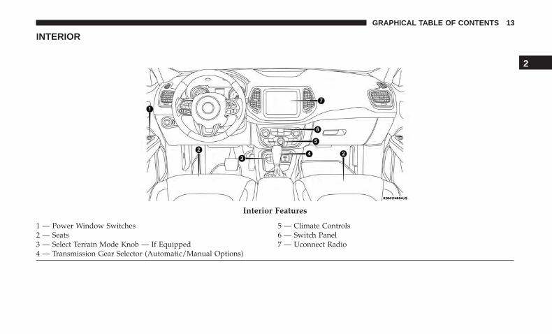
INTERIOR
Interior Features
1 — Power Window Switches 5 — Climate Controls2 — Seats 6 — Switch Panel3 — Select Terrain Mode Knob — If Equipped 7 — Uconnect Radio4 — Transmission Gear Selector (Automatic/Manual Options)
2
GRAPHICAL TABLE OF CONTENTS 13

GETTING TO KNOW YOUR VEHICLE
CONTENTS� KEYS . . . . . . . . . . . . . . . . . . . . . . . . . . . . . . . . .19
▫ Key Fob . . . . . . . . . . . . . . . . . . . . . . . . . . . . . .19
� IGNITION SWITCH . . . . . . . . . . . . . . . . . . . . . . .24
▫ Keyless Enter-N-Go — Ignition . . . . . . . . . . . . . .24
▫ Vehicle On Message . . . . . . . . . . . . . . . . . . . . .25
� REMOTE START — IF EQUIPPED . . . . . . . . . . . . .26
▫ How To Use Remote Start — If Equipped . . . . . .26
▫ Remote Start Abort Message On The InstrumentCluster Display — If Equipped . . . . . . . . . . . . . .27
▫ To Enter Remote Start Mode . . . . . . . . . . . . . . . .28
▫ To Exit Remote Start Mode Without Driving TheVehicle . . . . . . . . . . . . . . . . . . . . . . . . . . . . . . .28
▫ To Exit Remote Start Mode And Drive TheVehicle . . . . . . . . . . . . . . . . . . . . . . . . . . . . . . .28
▫ Remote Start Comfort Systems — If Equipped . . .29
▫ Remote Start Windshield Wiper De–IcerActivation — If Equipped. . . . . . . . . . . . . . . . . .29
▫ General Information . . . . . . . . . . . . . . . . . . . . .29
� SENTRY KEY . . . . . . . . . . . . . . . . . . . . . . . . . . . .30
▫ Replacement Keys . . . . . . . . . . . . . . . . . . . . . . .30
▫ Customer Key Programming . . . . . . . . . . . . . . .31
▫ General Information . . . . . . . . . . . . . . . . . . . . .31
� VEHICLE SECURITY ALARM — IF EQUIPPED . . .31
▫ Rearming Of The System . . . . . . . . . . . . . . . . . .31
▫ To Arm The System . . . . . . . . . . . . . . . . . . . . .32
▫ To Disarm The System . . . . . . . . . . . . . . . . . . .32
▫ Security System Manual Override . . . . . . . . . . . .32
� DOORS . . . . . . . . . . . . . . . . . . . . . . . . . . . . . . .33
▫ Manual Door Locks . . . . . . . . . . . . . . . . . . . . . .33
3

▫ Power Door Locks . . . . . . . . . . . . . . . . . . . . . .33
▫ Keyless Enter-N-Go — Passive Entry . . . . . . . . .34
▫ Automatic Unlock Doors On Exit . . . . . . . . . . . .38
▫ Child-Protection Door Lock System —Rear Doors . . . . . . . . . . . . . . . . . . . . . . . . . . . .38
� SEATS . . . . . . . . . . . . . . . . . . . . . . . . . . . . . . . .39
▫ Manual Seats — If Equipped . . . . . . . . . . . . . . .39
▫ Power Seats — If Equipped . . . . . . . . . . . . . . . .42
▫ Front Heated Seats — If Equipped . . . . . . . . . . .43
▫ 60/40 Split Folding Rear Seat With Fold-FlatFeature . . . . . . . . . . . . . . . . . . . . . . . . . . . . . .44
� HEAD RESTRAINTS . . . . . . . . . . . . . . . . . . . . . .46
▫ Front Head Restraint Adjustment . . . . . . . . . . . .46
▫ Rear Head Restraints . . . . . . . . . . . . . . . . . . . . .48
� STEERING WHEEL . . . . . . . . . . . . . . . . . . . . . . .49
▫ Tilt/Telescoping Steering Column . . . . . . . . . . . .49
▫ Heated Steering Wheel — If Equipped . . . . . . . .49
� MIRRORS . . . . . . . . . . . . . . . . . . . . . . . . . . . . . .50
▫ Inside Day/Night Mirror — If Equipped . . . . . .50
▫ Electrochromic Mirror — If Equipped . . . . . . . . .51
▫ Outside Mirrors . . . . . . . . . . . . . . . . . . . . . . . .52
▫ Power Adjustment Mirrors . . . . . . . . . . . . . . . . .52
▫ Folding Mirrors . . . . . . . . . . . . . . . . . . . . . . . . .53
▫ Heated Mirrors — If Equipped . . . . . . . . . . . . .54
▫ Illuminated Vanity Mirrors . . . . . . . . . . . . . . . .54
� EXTERIOR LIGHTS . . . . . . . . . . . . . . . . . . . . . . .55
▫ Headlight Switch . . . . . . . . . . . . . . . . . . . . . . .55
▫ Daytime Running Lights (DRL) — If Equipped . .55
▫ Multifunction Lever . . . . . . . . . . . . . . . . . . . . .56
▫ High/Low Beam Switch . . . . . . . . . . . . . . . . . .56
▫ Automatic High Beam Headlamp Control —If Equipped . . . . . . . . . . . . . . . . . . . . . . . . . . .56
▫ Flash-To-Pass . . . . . . . . . . . . . . . . . . . . . . . . . .57
▫ Automatic Headlights — If Equipped . . . . . . . . .57
▫ Headlight Time Delay . . . . . . . . . . . . . . . . . . . .57
16 GETTING TO KNOW YOUR VEHICLE
▫ Lights-On Reminder . . . . . . . . . . . . . . . . . . . . .58
▫ Fog Lights — If Equipped . . . . . . . . . . . . . . . . .58
▫ Turn Signals . . . . . . . . . . . . . . . . . . . . . . . . . . .59
▫ Lane Change Assist . . . . . . . . . . . . . . . . . . . . . .59
▫ Battery Saver Feature . . . . . . . . . . . . . . . . . . . .59
� INTERIOR LIGHTS . . . . . . . . . . . . . . . . . . . . . . .59
▫ Interior Courtesy Lights . . . . . . . . . . . . . . . . . .59
� WINDSHIELD WIPERS AND WASHERS . . . . . . . .61
▫ Windshield Wiper Operation. . . . . . . . . . . . . . . .61
▫ Rain Sensing Wipers — If Equipped . . . . . . . . . .63
▫ Rear Window Wiper/Washer . . . . . . . . . . . . . . .64
▫ Windshield Wiper De-Icer — If Equipped . . . . . .64
� CLIMATE CONTROLS . . . . . . . . . . . . . . . . . . . . .65
▫ Climate Controls Without A TouchscreenOverview . . . . . . . . . . . . . . . . . . . . . . . . . . . . .65
▫ Climate Controls With A TouchscreenOverview . . . . . . . . . . . . . . . . . . . . . . . . . . . . .69
▫ Climate Control Functions . . . . . . . . . . . . . . . . .75
▫ Automatic Temperature Control (ATC) —If Equipped . . . . . . . . . . . . . . . . . . . . . . . . . . .75
▫ Operating Tips . . . . . . . . . . . . . . . . . . . . . . . . .76
� WINDOWS . . . . . . . . . . . . . . . . . . . . . . . . . . . . .78
▫ Power Window Controls . . . . . . . . . . . . . . . . . .78
▫ Auto-Down Feature . . . . . . . . . . . . . . . . . . . . .79
▫ Auto-Up Feature With Anti-Pinch Protection . . . .79
▫ Reset Auto-Up. . . . . . . . . . . . . . . . . . . . . . . . . .80
▫ Window Lockout Switch. . . . . . . . . . . . . . . . . . .80
▫ Wind Buffeting . . . . . . . . . . . . . . . . . . . . . . . . .80
� POWER SUNROOF WITH POWER SHADE —IF EQUIPPED . . . . . . . . . . . . . . . . . . . . . . . . . . .81
▫ Opening Sunroof — Express . . . . . . . . . . . . . . . .82
▫ Opening Sunroof — Manual Mode . . . . . . . . . . .82
▫ Closing Sunroof — Express. . . . . . . . . . . . . . . . .82
▫ Closing Sunroof — Manual Mode . . . . . . . . . . . .82
▫ Venting Sunroof — Express. . . . . . . . . . . . . . . . .82
▫ Opening Power Shade — Express . . . . . . . . . . . .83
3
GETTING TO KNOW YOUR VEHICLE 17

▫ Opening Power Shade — Manual Mode . . . . . . .83
▫ Closing Power Shade — Express . . . . . . . . . . . . .83
▫ Closing Power Shade — Manual Mode . . . . . . . .83
▫ Pinch Protect Feature . . . . . . . . . . . . . . . . . . . . .84
▫ Wind Buffeting . . . . . . . . . . . . . . . . . . . . . . . . .84
▫ Sunroof Maintenance . . . . . . . . . . . . . . . . . . . . .84
� HOOD . . . . . . . . . . . . . . . . . . . . . . . . . . . . . . . .84
▫ Opening The Hood . . . . . . . . . . . . . . . . . . . . . .84
▫ Closing The Hood . . . . . . . . . . . . . . . . . . . . . . .85
� LIFTGATE . . . . . . . . . . . . . . . . . . . . . . . . . . . . .86
▫ Opening . . . . . . . . . . . . . . . . . . . . . . . . . . . . .86
▫ Closing . . . . . . . . . . . . . . . . . . . . . . . . . . . . . .86
▫ Power Liftgate — If Equipped . . . . . . . . . . . . . .87
▫ Cargo Area Features . . . . . . . . . . . . . . . . . . . . .89
� INTERNAL EQUIPMENT . . . . . . . . . . . . . . . . . . .92
▫ Storage . . . . . . . . . . . . . . . . . . . . . . . . . . . . . . .92
▫ Cupholders . . . . . . . . . . . . . . . . . . . . . . . . . . .93
▫ Power Outlets . . . . . . . . . . . . . . . . . . . . . . . . .93
▫ Power Inverter — If Equipped . . . . . . . . . . . . . .96
� ROOF LUGGAGE RACK — IF EQUIPPED . . . . . .96
18 GETTING TO KNOW YOUR VEHICLE

KEYS
Key Fob
Your vehicle uses a keyless ignition system. The ignitionsystem consists of a key fob with Remote Keyless Entry(RKE) and a START/STOP push button ignition system.The Remote Keyless Entry system consists of a key fob andKeyless Enter-N-Go feature if equipped.
NOTE: The key fob may not be found if it is located next toa mobile phone, laptop or other electronic device; thesedevices may block the key fob’s wireless signal.
The key fob allows you to lock or unlock the doors andliftgate from distances up to approximately 66 ft (20 m)using a handheld key fob. The key fob does not need to bepointed at the vehicle to activate the system.
The key fob also includes an emergency key, which storesin the rear of the key fob.
The emergency key allows for entry into the vehicle shouldthe battery in the vehicle or the key fob go dead. Theemergency key is also for locking the glove compartment.You can keep the emergency key with you when valetparking.
To remove the emergency key, slide the mechanical latch atthe top of the key fob sideways with your thumb and thenpull the key out with your other hand.
Key Fob
3
GETTING TO KNOW YOUR VEHICLE 19
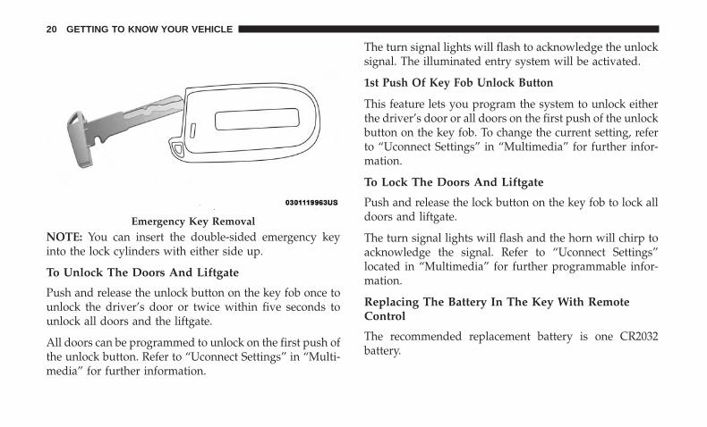
NOTE: You can insert the double-sided emergency keyinto the lock cylinders with either side up.
To Unlock The Doors And Liftgate
Push and release the unlock button on the key fob once tounlock the driver’s door or twice within five seconds tounlock all doors and the liftgate.
All doors can be programmed to unlock on the first push ofthe unlock button. Refer to “Uconnect Settings” in “Multi-media” for further information.
The turn signal lights will flash to acknowledge the unlocksignal. The illuminated entry system will be activated.
1st Push Of Key Fob Unlock Button
This feature lets you program the system to unlock eitherthe driver’s door or all doors on the first push of the unlockbutton on the key fob. To change the current setting, referto “Uconnect Settings” in “Multimedia” for further infor-mation.
To Lock The Doors And Liftgate
Push and release the lock button on the key fob to lock alldoors and liftgate.
The turn signal lights will flash and the horn will chirp toacknowledge the signal. Refer to “Uconnect Settings”located in “Multimedia” for further programmable infor-mation.
Replacing The Battery In The Key With RemoteControl
The recommended replacement battery is one CR2032battery.
Emergency Key Removal
20 GETTING TO KNOW YOUR VEHICLE

NOTE:
• Perchlorate Material — special handling may apply. Seewww.dtsc.ca.gov/hazardouswaste/perchlorate for fur-ther information.
• Do not touch the battery terminals that are on the backhousing or the printed circuit board.
Key Fob:
1. Remove the emergency key by sliding the mechanicallatch on the back of the key fob sideways with yourthumb and pull the emergency key out with your otherhand.
2. Separate the key fob halves using the tip of the emer-gency key, a #2 flat blade screwdriver, or a coin andgently pry the two halves of the key fob apart. Makesure not to damage the seal during removal.
Emergency Key Removal
1 — Emergency Key Release Button2 — Emergency Key
3
GETTING TO KNOW YOUR VEHICLE 21

Emergency Key Removal Separating Case With A Coin
22 GETTING TO KNOW YOUR VEHICLE

3. Remove the battery by turning the back cover over(battery facing downward) and tapping it lightly on asolid surface such as a table or similar and replace thebattery. When replacing the battery, match the + sign onthe battery to the + sign on the inside of the battery clip,located on the back cover. Avoid touching the newbattery with your fingers. Skin oils may cause batterydeterioration. If you touch a battery, clean it withrubbing alcohol.
4. To assemble the key fob case, snap the two halvestogether.
Programming Additional Key Fobs
Programming the key fob may be performed by yourauthorized dealer.
Request For Additional Key Fobs
NOTE: Only key fobs that are programmed to the vehicleelectronics can be used to start and operate the vehicle.Once a key fob is programmed to a vehicle, it cannot beprogrammed to any other vehicle.
WARNING!
• Always remove the key fobs from the vehicle andlock all doors when leaving the vehicle unattended.
• For vehicles equipped with Keyless Enter-N-Go —Ignition, always remember to place the ignition inthe OFF mode.
Duplication of key fobs may be performed at your autho-rized dealer. This procedure consists of programming ablank key fob to the vehicle electronics. A blank key fob isone that has never been programmed.
NOTE: When having the Sentry Key Immobilizer Systemserviced, bring all vehicle keys with you to your autho-rized dealer.
Key Fob Battery Replacement
3
GETTING TO KNOW YOUR VEHICLE 23

General Information
The following regulatory statement applies to all radiofrequency (RF) devices equipped in this vehicle:
This device complies with Part 15 of the FCC Rules andwith Industry Canada license-exempt RSS standard(s).Operation is subject to the following two conditions:
1. This device may not cause harmful interference, and
2. This device must accept any interference received, includ-ing interference that may cause undesired operation.
NOTE: Changes or modifications not expressly approvedby the party responsible for compliance could void theuser’s authority to operate the equipment.
IGNITION SWITCH
Keyless Enter-N-Go — Ignition
This feature allows the driver to operate the ignition withthe push of a button as long as the key fob is in thepassenger compartment.
The START/STOP push button ignition has three operatingmodes. The three modes are OFF, ON/RUN, and START.
NOTE: If the ignition state/mode does not change with thepush of a button, the key fob may have a low or deadbattery. In this situation, a back up method can be used tooperate the ignition switch. Put the nose side (side oppositeof the emergency key) of the key fob against the ENGINESTART/STOP button and push to operate the ignition.
The push button ignition can be placed in the followingmodes:
OFF• The engine is stopped.• Some electrical devices (e.g. Central locking, alarm, etc.)
are still available.
START/STOP Ignition Button
24 GETTING TO KNOW YOUR VEHICLE

ON/RUN
• Driving mode.
• All the electrical devices are available.
START
• Start the engine.
WARNING!
• When exiting the vehicle, always remove the key fobfrom the vehicle and lock your vehicle.
• Never leave children alone in a vehicle, or withaccess to an unlocked vehicle.
• Allowing children to be in a vehicle unattended isdangerous for a number of reasons. A child or otherscould be seriously or fatally injured. Childrenshould be warned not to touch the parking brake,brake pedal or the gear selector.
• Do not leave the key fob in or near the vehicle, or ina location accessible to children, and do not leave theignition of a vehicle equipped with Keyless Enter-N-Go in the ON/RUN mode. A child could operatepower windows, other controls, or move the vehicle.
(Continued)
WARNING! (Continued)• Do not leave children or animals inside parked
vehicles in hot weather. Interior heat build-up maycause serious injury or death.
CAUTION!
An unlocked vehicle is an invitation for thieves. Al-ways remove key fob from the vehicle and lock alldoors when leaving the vehicle unattended.
NOTE: For further information, refer to �Starting TheEngine� in �Starting And Operating.�
Vehicle On Message
When opening the driver’s door and the ignition is inON/RUN (engine not running) mode, a chime will soundto remind you to place the ignition in the OFF mode. Inaddition to the chime, the Vehicle On message will displayin the cluster.
3
GETTING TO KNOW YOUR VEHICLE 25

NOTE: The power window switches and power sunroof (ifequipped) will remain active for three minutes after theignition is cycled to the OFF mode. Opening either frontdoor will cancel this feature. The time for this feature isprogrammable.
WARNING!
• Before exiting a vehicle, always shift the automatictransmission into PARK, apply the parking brake,place the engine in the OFF position, remove the keyfob from the vehicle and lock your vehicle. Alwaysmake sure the keyless ignition is in “OFF” position,remove the key fob from the vehicle and lock thevehicle.
• Never leave children alone in a vehicle, or withaccess to an unlocked vehicle.
• Allowing children to be in a vehicle unattended isdangerous for a number of reasons. A child or otherscould be seriously or fatally injured. Childrenshould be warned not to touch the parking brake,brake pedal or the gear selector.
• Do not leave the key fob in or near the vehicle, or ina location accessible to children, and do not leave the
(Continued)
WARNING! (Continued)ignition in the ON/RUN mode. A child could operatepower windows, other controls, or move the vehicle.
• Do not leave children or animals inside parkedvehicles in hot weather. Interior heat build-up maycause serious injury or death.
CAUTION!
An unlocked vehicle is an invitation for thieves. Al-ways remove key fob from the vehicle and lock alldoors when leaving the vehicle unattended.
REMOTE START — IF EQUIPPED
How To Use Remote Start — If Equipped
• Push remote start button on the key fob twicewithin five seconds. Pushing the remote startbutton a third time shuts the engine off.
• To drive the vehicle, push unlock button, insert the keyin the ignition and turn to the ON/RUN position.
26 GETTING TO KNOW YOUR VEHICLE

• With remote start, the engine will only run for 15minutes (timeout) unless the ignition key is placed in theON/RUN position.
• The vehicle must be started with the key after twoconsecutive timeouts.
All of the following conditions must be met before theengine will remote start:
• Gear selector in PARK
• Doors closed
• Hood closed
• Liftgate closed
• Hazard switch off
• Brake switch inactive (brake pedal not pushed)
• Battery at an acceptable charge level
• Check engine light shall not be present
• PANIC button not pushed
• System not disabled from previous remote start event
• Vehicle alarm system indicator flashing
• Ignition in STOP/OFF position
• Fuel level meets minimum requirement
• Vehicle security alarm is not signaling an intrusion
WARNING!
• Do not start or run an engine in a closed garage orconfined area. Exhaust gas contains Carbon Monox-ide (CO) which is odorless and colorless. CarbonMonoxide is poisonous and can cause serious injuryor death when inhaled.
• Keep key fobs away from children. Operation of theRemote Start System, windows, door locks or othercontrols could cause serious injury or death.
Remote Start Abort Message On The InstrumentCluster Display — If Equipped
The following messages will display in the instrumentcluster display if the vehicle fails to remote start or exitsremote start prematurely:
• Remote Start Aborted — Door Open
• Remote Start Aborted — Hood Open
• Remote Start Aborted — Fuel Low
• Remote Start Aborted — Liftgate Open
3
GETTING TO KNOW YOUR VEHICLE 27

• Remote Start Disabled — Start Vehicle To Reset
• Remote Start Aborted — Too Cold
• Remote Start Aborted — Time Expired
The message will stay active until the ignition is turned tothe ON/RUN position.
To Enter Remote Start Mode
Push and release the remote start button on the key fobtwice within five seconds. The vehicle doors will lock, theparking lights will flash, and the horn will chirp twice (ifprogrammed). Then, the engine will start, and the vehiclewill remain in the Remote Start mode for a 15-minute cycle.
NOTE:
• If an engine fault is present or fuel level is low, thevehicle will start and then shut down in 10 seconds.
• The park lamps will turn on and remain on duringRemote Start mode.
• For security, power window and power sunroof opera-tion (if equipped) are disabled when the vehicle is in theRemote Start mode.
• The engine can be started two consecutive times withthe key fob. However, the ignition must be cycled by
pushing the START/STOP button twice (or the ignitionswitch must be cycled to the ON/RUN position) beforeyou can repeat the start sequence for a third cycle.
To Exit Remote Start Mode Without Driving TheVehicle
Push and release the remote start button one time or allowthe engine to run for the entire 15-minute cycle.
NOTE: To avoid unintentional shutdowns, the system willdisable with a one time push of the remote start button fortwo seconds after receiving a valid remote start request.
To Exit Remote Start Mode And Drive The Vehicle
Before the end of 15-minute cycle, push and release theunlock button on the key fob to unlock the doors anddisarm the vehicle security alarm (if equipped). Then, priorto the end of the 15-minute cycle, push and release theSTART/STOP button. If the START/STOP button is notpresent, insert the key fob into the ignition switch and turnthe switch to the ON/RUN position.
NOTE:
• For vehicles not equipped with the Keyless Enter-N-Go— Passive Entry feature, the ignition switch must be inthe ON/RUN position in order to drive the vehicle.
28 GETTING TO KNOW YOUR VEHICLE
• For vehicles not equipped with the Keyless Enter-N-Go— Passive Entry feature, the message “Remote StartActive — Insert Key and Turn To Run” will show in theinstrument cluster display until you insert the key.
• For vehicles equipped with the Keyless Enter-N-Go —Passive Entry feature, the message “Remote Start Active— Push Start Button” will will show in the instrumentcluster display until you push the START button.
Remote Start Comfort Systems — If Equipped
When remote start is activated, the heated steering wheeland driver heated seat features will automatically turn onin cold weather. In warm weather, the driver vented seatfeature will automatically turn on when the remote start isactivated. These features will stay on through the durationof remote start or until the ignition switch is cycled to theON/RUN position.
Remote Start Windshield Wiper De–Icer Activation— If Equipped
When remote start is active and the outside ambienttemperature is less than 40°F (4.4°C), the Windshield WiperDe-Icer will be enabled. Exiting remote start will resume
previous operation, except if the Windshield Wiper De-Iceris active. The Windshield Wiper De-Icer timer and opera-tion will continue.
General Information
The following regulatory statement applies to all radiofrequency (RF) devices equipped in this vehicle:
This device complies with Part 15 of the FCC Rules andwith Industry Canada license-exempt RSS standard(s).Operation is subject to the following two conditions:
1. This device may not cause harmful interference, and
2. This device must accept any interference received, in-cluding interference that may cause undesired opera-tion.
NOTE: Changes or modifications not expressly approvedby the party responsible for compliance could void theuser’s authority to operate the equipment.
3
GETTING TO KNOW YOUR VEHICLE 29

SENTRY KEY
The Sentry Key Immobilizer system prevents unauthorizedvehicle operation by disabling the engine. The system doesnot need to be armed or activated. Operation is automatic,regardless of whether the vehicle is locked or unlocked.
The system uses a key fob, keyless push button ignitionand a RF receiver to prevent unauthorized vehicle opera-tion. Therefore, only key fobs that are programmed to thevehicle can be used to start and operate the vehicle. Thesystem will not allow the engine to crank if an invalid keyfob is used to start and operate the vehicle. The system willshut the engine off in two seconds if an invalid key fob isused to start the engine.
After turning the ignition switch to the ON/RUN position,the vehicle security light will turn on for three seconds fora bulb check. If the light remains on after the bulb check, itindicates that there is a problem with the electronics. Inaddition, if the light begins to flash after the bulb check, itindicates that someone used an invalid key fob to start theengine. Either of these conditions will result in the enginebeing shut off after two seconds.
If the vehicle security light turns on during normal vehicleoperation (vehicle running for longer than ten seconds), itindicates that there is a fault in the electronics. Should this
occur, have the vehicle serviced as soon as possible by yourauthorized dealer.
CAUTION!
The Sentry Key Immobilizer system is not compatiblewith some aftermarket remote starting systems. Use ofthese systems may result in vehicle starting problemsand loss of security protection.
All of the key fobs provided with your new vehicle havebeen programmed to the vehicle electronics.
Replacement Keys
NOTE: Only key fobs that are programmed to the vehicleelectronics can be used to start and operate the vehicle.Once a key fob is programmed to a vehicle, it cannot beprogrammed to any other vehicle.
CAUTION!
• Always remove the key fobs from the vehicle andlock all doors when leaving the vehicle unattended.
• For vehicles equipped with Keyless Enter-N-Go —Ignition, always remember to place the ignition inthe OFF position.
30 GETTING TO KNOW YOUR VEHICLE

NOTE: Duplication of key fobs may be performed at yourauthorized dealer. This procedure consists of programminga blank key fob to the vehicle electronics. A blank key fobis one that has never been programmed.
When having the Sentry Key Immobilizer System serviced,bring all vehicle keys with you to your authorized dealer.
Customer Key Programming
Programming key fobs may be performed at your autho-rized dealer.
General Information
The following regulatory statement applies to all radiofrequency (RF) devices equipped in this vehicle:
This device complies with Part 15 of the FCC Rules andwith Industry Canada license-exempt RSS standard(s).Operation is subject to the following two conditions:
1. This device may not cause harmful interference, and
2. This device must accept any interference received, in-cluding interference that may cause undesired opera-tion.
NOTE: Changes or modifications not expressly approvedby the party responsible for compliance could void theuser’s authority to operate the equipment.
VEHICLE SECURITY ALARM — IF EQUIPPED
The vehicle security alarm monitors the vehicle doors,hood, liftgate, and the Keyless Enter-N-Go — Ignition forunauthorized operation. While the vehicle security alarm isarmed, interior switches for door locks and liftgate releaseare disabled. If something triggers the alarm, the vehiclesecurity alarm will provide the following audible andvisible signals:
• The horn will pulse
• The turn signals will flash
• The vehicle security light in the instrument cluster willflash
Rearming Of The System
If something triggers the alarm, and no action is taken todisarm it, the vehicle security alarm will turn the horn offafter approximately 90 seconds, and then the vehiclesecurity alarm will rearm itself.
3
GETTING TO KNOW YOUR VEHICLE 31

To Arm The System
Follow these steps to arm the vehicle security alarm:
1. Make sure the vehicle’s ignition is placed in the “OFF”mode.
2. Perform one of the following methods to lock thevehicle:• Push the lock button on the interior power door lock
switch with the driver and/or passenger door open.• Push the lock button on the key fob.
3. If any doors are open, close them.
To Disarm The System
The vehicle security alarm can be disarmed using any ofthe following methods:
• Push the unlock button on the key fob.
• Cycle the ignition out of the off mode to disarm thesystem.
NOTE:
• The driver’s door key cylinder and the liftgate button onthe key fob cannot arm or disarm the vehicle securityalarm.
• The vehicle security alarm remains armed during powerliftgate entry. Pushing the liftgate button will not disarmthe vehicle security alarm. If someone enters the vehiclethrough the liftgate and opens any door, the alarm willsound.
• When the vehicle security alarm is armed, the interiorpower door lock switches will not unlock the doors.
The vehicle security alarm is designed to protect yourvehicle. However, you can create conditions where thesystem will give you a false alarm. If one of the previouslydescribed arming sequences has occurred, the vehiclesecurity alarm will arm regardless of whether you are inthe vehicle or not. If you remain in the vehicle and open adoor, the alarm will sound. If this occurs, disarm thevehicle security alarm.
If the vehicle security alarm is armed and the batterybecomes disconnected, the vehicle security alarm willremain armed when the battery is reconnected; the exteriorlights will flash, and the horn will sound. If this occurs,disarm the vehicle security alarm.
Security System Manual Override
The vehicle security alarm will not arm if you lock thedoors using the manual door lock plunger.
32 GETTING TO KNOW YOUR VEHICLE

DOORS
Manual Door Locks
To lock each door, rotate the door lock knob on each doortrim panel forward until the lock indicator is shown. Tounlock the front doors, pull the inside door handle to thefirst detent or rotate the door lock button until the lockindicator is hidden. To unlock the rear doors, rotate thedoor lock button until the lock indicator is hidden.
If the door lock button is locked (lock indicator visible)when you shut the door, the door will remain locked.Therefore, make sure the key fob is not inside the vehiclebefore closing the door.
NOTE: The manual door locks will not lock or unlock theliftgate.
WARNING!
• For personal security and safety in the event of acollision, lock the vehicle doors before you drive aswell as when you park and exit the vehicle.
• When exiting the vehicle, always remove the key fobfrom the vehicle and lock your vehicle. If equipped
(Continued)
WARNING! (Continued)with Keyless Enter-N-Go — Ignition, always makesure the keyless ignition node is in “OFF” mode,remove the key fob from the vehicle and lock thevehicle. Unsupervised use of vehicle equipment maycause severe personal injuries or death.
• Never leave children alone in a vehicle, or withaccess to an unlocked vehicle. Allowing children tobe in a vehicle unattended is dangerous for a numberof reasons. A child or others could be seriously orfatally injured. Children should be warned not totouch the parking brake, brake pedal or the gearselector.
• Do not leave the key fob in or near the vehicle, or ina location accessible to children, and do not leave theignition of a vehicle equipped with Keyless Enter-N-Go — Ignition the ACC or ON/RUN mode. A childcould operate power windows, other controls, ormove the vehicle.
Power Door Locks
A power door lock switch is located on each of the frontdoor trim panels. Use this switch to lock or unlock thedoors, liftgate and fuel door.
3
GETTING TO KNOW YOUR VEHICLE 33

If you push the power door lock switch while the ignitionis in the ON/RUN position, and any door or the liftgate isopen, the power locks will not operate. This prevents youfrom accidentally locking the key fob in the vehicle. Placingthe ignition in the OFF position or closing the doors andliftgate will allow the locks to operate. If the driver door isopen, and the ignition is in the RUN position, a chime willsound as a reminder to remove the key.
Keyless Enter-N-Go — Passive Entry
The Passive Entry system is an enhancement to the vehi-cle’s Remote Keyless Entry system and a feature of KeylessEnter-N-Go — Passive Entry. This feature allows you tolock and unlock the vehicle’s door(s) and fuel door withouthaving to push the key fob lock or unlock buttons.
NOTE:
• Passive Entry may be programmed ON/OFF; refer to“Uconnect Settings” in “Multimedia” for further infor-mation.
• If wearing gloves on your hands, or if it has beenraining/snowing on the Passive Entry door handle, theunlock sensitivity can be affected, resulting in a slowerresponse time.
• If the vehicle is unlocked by Passive Entry and no dooris opened within 60 seconds, the vehicle will re-lock andif equipped will arm the security alarm.
• The key fob may not be able to be detected by thePassive Entry system if it is located next to a mobilephone, laptop or other electronic device; these devicesmay block the key fob’s wireless signal and prevent thePassive Entry system from locking and unlocking thevehicle.
Power Door Lock Switch
34 GETTING TO KNOW YOUR VEHICLE
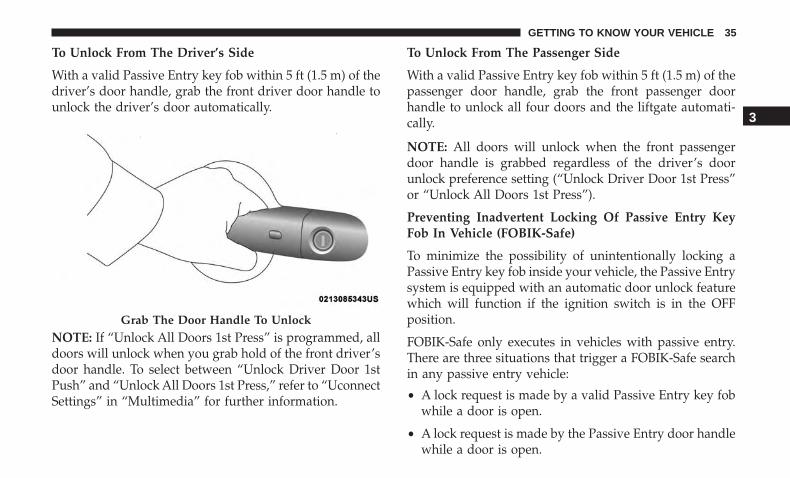
To Unlock From The Driver’s Side
With a valid Passive Entry key fob within 5 ft (1.5 m) of thedriver’s door handle, grab the front driver door handle tounlock the driver’s door automatically.
NOTE: If “Unlock All Doors 1st Press” is programmed, alldoors will unlock when you grab hold of the front driver’sdoor handle. To select between “Unlock Driver Door 1stPush” and “Unlock All Doors 1st Press,” refer to “UconnectSettings” in “Multimedia” for further information.
To Unlock From The Passenger Side
With a valid Passive Entry key fob within 5 ft (1.5 m) of thepassenger door handle, grab the front passenger doorhandle to unlock all four doors and the liftgate automati-cally.
NOTE: All doors will unlock when the front passengerdoor handle is grabbed regardless of the driver’s doorunlock preference setting (“Unlock Driver Door 1st Press”or “Unlock All Doors 1st Press”).
Preventing Inadvertent Locking Of Passive Entry KeyFob In Vehicle (FOBIK-Safe)
To minimize the possibility of unintentionally locking aPassive Entry key fob inside your vehicle, the Passive Entrysystem is equipped with an automatic door unlock featurewhich will function if the ignition switch is in the OFFposition.
FOBIK-Safe only executes in vehicles with passive entry.There are three situations that trigger a FOBIK-Safe searchin any passive entry vehicle:
• A lock request is made by a valid Passive Entry key fobwhile a door is open.
• A lock request is made by the Passive Entry door handlewhile a door is open.
Grab The Door Handle To Unlock
3
GETTING TO KNOW YOUR VEHICLE 35
• A lock request is made by the door panel switch whilethe door is open.
When any of these situations occur, after all open doors areshut, the FOBIK-Safe search will be executed. If it finds aPassive Entry key fob inside the car and it does not findany Passive Entry key fobs outside the car, then the car willunlock and alert the customer.
NOTE: The vehicle will only unlock the doors when a validPassive Entry key fob is detected inside the vehicle. Thevehicle will not unlock the doors when any of the follow-ing conditions are true:
• The doors are manually locked using the door lockknobs.
• There is a valid Passive Entry key fob outside the vehicleand within 5 ft (1.5m) of either Passive Entry doorhandle.
• Three attempts are made to lock the doors using thedoor panel switch and then close the doors.
To Unlock/Enter The Liftgate
The liftgate passive entry unlock feature is built intoliftgate handle release. With a valid Passive Entry key fobwithin 5 ft (1.5 m) of the liftgate, push the electronic liftgaterelease to open with one fluid motion.
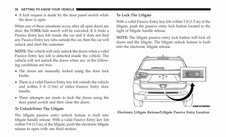
To Lock The Liftgate
With a valid Passive Entry key fob within 5 ft (1.5 m) of theliftgate, push the passive entry lock button located to theright of liftgate handle release.
NOTE: The liftgate passive entry lock button will lock alldoors and the liftgate. The liftgate unlock feature is builtinto the electronic liftgate release.
Electronic Liftgate Release/Liftgate Passive Entry Location
36 GETTING TO KNOW YOUR VEHICLE

To Lock The Vehicle’s Doors And Liftgate
With one of the vehicle’s Passive Entry key fob within 5 ft(1.5 m) of the driver or passenger front door handles, pushthe passive entry lock button located on the outside doorhandle, to lock the vehicle doors and liftgate.
NOTE: DO NOT grab the door handle, when pushing thedoor handle lock button. This could unlock the door(s).
NOTE:
• After pushing the door handle button, you must waittwo seconds before you can lock or unlock the doors,using either Passive Entry door handle. This is done toallow you to check if the vehicle is locked by pulling thedoor handle without the vehicle reacting and unlocking.
• If Passive Entry is disabled using the Uconnect System,the key protection described in �Preventing InadvertentLocking of Passive Entry key fob in Vehicle� remainsactive/functional.
Push The Door Handle Button To Lock
DO NOT Grab The Door Handle When Locking
3
GETTING TO KNOW YOUR VEHICLE 37

• The Passive Entry system will not operate if the key fobbattery is dead.
The vehicle doors can also be locked by using the lockbutton located on the vehicle’s interior door panel.
Automatic Unlock Doors On Exit
The doors will unlock automatically on vehicles withpower door locks if:
1. The Automatic Unlock Doors On Exit feature is enabled.
2. All doors are closed.
3. The transmission gear selector was not in PARK, then isplaced in PARK.
4. Any door is opened.
Child-Protection Door Lock System — Rear Doors
To provide a safer environment for small children riding inthe rear seats, the rear doors are equipped with a Child-Protection Door Lock system.
To use the system, open each rear door, use a flat bladescrewdriver (or emergency key) and rotate the dial to the lockor unlock position. When the system on a door is engaged,that door can only be opened by using the outside doorhandle even if the inside door lock is in the unlocked position.
NOTE:
• When the child lock system is engaged, the door can beopened only by using the outside door handle eventhough the inside door lock is in the unlocked position.
• After disengaging the Child-Protection Door Lock sys-tem, always test the door from the inside to make certainit is in the desired position.
• After engaging the Child-Protection Door Lock system,always test the door from the inside to make certain it isin the desired position.
Child-Protection Door Lock Function
38 GETTING TO KNOW YOUR VEHICLE

• For emergency exit with the system engaged, rotate thedoor lock button until the lock indicator is hidden(unlocked position), roll down the window, and openthe door with the outside door handle.
WARNING!
Avoid trapping anyone in a vehicle in a collision.Remember that the rear doors can only be opened fromthe outside when the Child-Protection locks are en-gaged (locked).
SEATS
Seats are a part of the Occupant Restraint System of thevehicle.
WARNING!
• It is dangerous to ride in a cargo area, inside or outsideof a vehicle. In a collision, people riding in these areasare more likely to be seriously injured or killed.
• Do not allow people to ride in any area of yourvehicle that is not equipped with seats and seat belts.
(Continued)
WARNING! (Continued)In a collision, people riding in these areas are morelikely to be seriously injured or killed.
• Be sure everyone in your vehicle is in a seat andusing a seat belt properly.
Manual Seats — If Equipped
Manual Front Seat Forward/Rearward Adjustment
On models equipped with manual seats, the adjusting baris located at the front of the seats, near the floor.
Front Seat Adjustment
3
GETTING TO KNOW YOUR VEHICLE 39

While sitting in the seat, lift up on the bar and move theseat forward or rearward. Release the bar once you havereached the desired position. Then, using body pressure,move forward and rearward on the seat to be sure that theseat adjusters have latched.
WARNING!
• Adjusting a seat while driving may be dangerous.Moving a seat while driving could result in loss ofcontrol which could cause a collision and seriousinjury or death.
• Seats should be adjusted before fastening the seatbelts and while the vehicle is parked. Serious injuryor death could result from a poorly adjusted seat belt.
Manual Seat Height Adjustment — If Equipped
The driver’s seat height can be raised or lowered by usinga lever, located on the outboard side of the seat. Pullupward on the lever to raise the seat height or pushdownward on the lever to lower the seat height.
Manual Front Seat Recline Adjustment
To adjust the seatback, lift the lever located on the outboardside of the seat, lean back to the desired position andrelease the lever. To return the seatback, lift the lever, leanforward and release the lever.
Seat Height Adjustment
40 GETTING TO KNOW YOUR VEHICLE

WARNING!
Do not ride with the seatback reclined so that theshoulder belt is no longer resting against your chest. Ina collision you could slide under the seat belt, whichcould result in serious injury or death.
Fold-Forward Front Passenger Seat — If Equipped
This feature allows for extended cargo space. When theseat is folded flat, it is an extension of the load floor surface(allowing long cargo to fit from the rear hatch up to theinstrument panel). The fold-forward seat back has a soft-back surface that you cannot use as a work surface whenthe seat is folded forward and the vehicle is not in motion.
Pull upward on the recline lever to fold or unfold the seat.
NOTE: You may experience deformation in the seat cush-ion from the seat belt buckles if the seats are left folded foran extended period of time. This is normal and by simplyopening the seats to the open position, over time the seatcushion will return to its normal shape.
WARNING!
Adjusting a seat while the vehicle is moving is dan-gerous. The sudden movement of the seat could causeyou to lose control. Adjust any seat only while thevehicle is parked.
Recline Lever
3
GETTING TO KNOW YOUR VEHICLE 41

Power Seats — If Equipped
Some models may be equipped with a power driver’s seatand/or power passenger seat. The power seat switch andpower seat recliner switch are located on the outboard sideof the seat near the floor. Use the power seat switch toadjust seat height, angle, or forward/rearward position.Use the power seat recline switch to adjust the angle of theseat back.
Forward Or Rearward Adjustment
The seat can be adjusted both forward and rearward. Pushthe seat switch forward or rearward, the seat will move inthe direction of the switch. Release the switch when thedesired position has been reached.
Height Adjustment
The height of the seats can be adjusted up or down. Pullupward or push downward on the seat switch, the seat willmove in the direction of the switch. Release the switchwhen the desired position is reached.
Tilt Adjustment
The angle of the seat cushion can be adjusted up or down.Pull upward or push downward on the front of the seatswitch and the front of the seat cushion will move in thedirection of the switch.
Reclining The Seatback Forward Or Rearward
The seatback can be reclined both forward and rearward.Push the seat recliner switch forward or rearward. Theseatback will move in the direction of the switch. Releasethe switch when the desired position has been reached.
Power Seat Switch
42 GETTING TO KNOW YOUR VEHICLE

WARNING!
Do not ride with the seatback reclined so that theshoulder belt is no longer resting against your chest. Ina collision you could slide under the seat belt, whichcould result in serious injury or death.
Power Lumbar — If Equipped
Vehicles equipped with power driver or passenger seatsmay be equipped with power lumbar. The power lumbarswitch is located on the outboard side of the power seat.
Push the switch forward or rearward to increase or de-crease the lumbar support. Push the switch upward ordownward to raise or lower the lumbar support.
Front Heated Seats — If Equipped
The front heated seats control buttons are located withinthe Uconnect system. You can gain access to the controlbuttons through the climate screen or the controls screen.
• Press the heated seat button once to turn the HIsetting on.
• Press the heated seat button a second time to turnthe LO setting on.
Power Seat Recliner Switch
Power Lumbar Switch
3
GETTING TO KNOW YOUR VEHICLE 43

• Press the heated seat button a third time to turn theheating elements off.
If your vehicle is equipped with automatic temperaturecontrols with an integrated center stack, or manual tem-perature controls, you’ll find the heated seat switches onthe switch bank below the radio screen.
If the HI level setting is selected, the system will automati-cally switch to LO level after approximately 60 minutes ofcontinuous operation. At that time, the display will changefrom HI to LO, indicating the change. The LO level settingwill turn off automatically after approximately 45 minutes.
NOTE: The engine must be running for the heated seats tooperate.
Vehicles With Remote Start — If Equipped
On models that are equipped with remote start, the heatedseats can be programmed to come on during a remote start.
This feature can be programmed through the Uconnectsystem. Refer to “Uconnect Settings” in “Multimedia” forfurther information.
WARNING!
• Persons who are unable to feel pain to the skinbecause of advanced age, chronic illness, diabetes,spinal cord injury, medication, alcohol use, exhaus-tion or other physical condition must exercise carewhen using the seat heater. It may cause burns evenat low temperatures, especially if used for longperiods of time.
• Do not place anything on the seat or seatback thatinsulates against heat, such as a blanket or cushion.This may cause the seat heater to overheat. Sitting ina seat that has been overheated could cause seriousburns due to the increased surface temperature of theseat.
60/40 Split Folding Rear Seat With Fold-FlatFeature
To provide additional storage area, each rear seat can befolded flat. This allows for extended cargo space and stillmaintains some rear seating room.
44 GETTING TO KNOW YOUR VEHICLE

NOTE: Prior to folding the rear seat, it may be necessary toposition the front seat to its mid-track position. Also, besure that the front seats are fully upright and positionedforward. This will allow the rear seat to fold down easily.
WARNING!
• It is extremely dangerous to ride in a cargo area,inside or outside of a vehicle. In a collision, peopleriding in these areas are more likely to be seriouslyinjured or killed.
• Do not allow people to ride in any area of yourvehicle that is not equipped with seats and seat belts.
• Be sure everyone in your vehicle is in a seat andusing a seat belt properly.
To Lower The Rear Seat
1. Pull the seatback release lever located on either side ofthe upper outer edge of the seat.
2. Fold that side of the rear seatback completely forward.
To Raise The Rear Seat
NOTE: If interference from the cargo area prevents theseatback from fully locking, you will have difficulty return-ing the seat to its proper position.
Raise the seatback and lock it into place.
Rear Seat Release Lever
1 — Seatback Release Levers2 — Seat Belt Guide
3
GETTING TO KNOW YOUR VEHICLE 45

The release lever will show a red indicator while in theunlocked position. Once the seat is locked in, the redindicator will no longer be visible.
WARNING!
Be certain that the seatback is securely locked intoposition. If the seatback is not securely locked intoposition the seat will not provide the proper stabilityfor child seats and/or passengers. An improperlylatched seat could cause serious injury.
HEAD RESTRAINTS
Head restraints are designed to reduce the risk of injury byrestricting head movement in the event of a rear impact.Head restraints should be adjusted so that the top of thehead restraint is located above the top of your ear.
WARNING!
• All occupants, including the driver, should not operatea vehicle or sit in a vehicle’s seat until the headrestraints are placed in their proper positions in order tominimize the risk of neck injury in the event of a crash.
(Continued)
WARNING! (Continued)• Head restraints should never be adjusted while the
vehicle is in motion. Driving a vehicle with the headrestraints improperly adjusted or removed could causeserious injury or death in the event of a collision.
NOTE: Do not reverse the head restraints (making the rearof the head restraint face forward) in an attempt to gainadditional clearance to the back of your head.
Front Head Restraint Adjustment
Your vehicle is equipped with front four way driver andpassenger head restraints.
To raise the head restraint, pull upward on the headrestraint. To lower the head restraint, push the adjustmentbutton, located at the base of the head restraint, and pushdownward on the head restraint.
To adjust the head restraint forward, pull the top of thehead restraint toward the front of the vehicle as desiredand release. To adjust the head restraint rearward, pull thetop of the head restraint to the forward most position andrelease. The head restraint will return to the rear mostposition.
46 GETTING TO KNOW YOUR VEHICLE

NOTE: The head restraints should only be removed byqualified technicians, for service purposes only. If either ofthe head restraints require removal, see your authorizeddealer.
WARNING!
• All occupants, including the driver, should not operatea vehicle or sit in a vehicle’s seat until the headrestraints are placed in their proper positions in order tominimize the risk of neck injury in the event of a crash.
• Head restraints should never be adjusted while thevehicle is in motion. Driving a vehicle with the headrestraints improperly adjusted or removed couldcause serious injury or death in the event of acollision.
Head Restraint Adjustment Button
3
GETTING TO KNOW YOUR VEHICLE 47
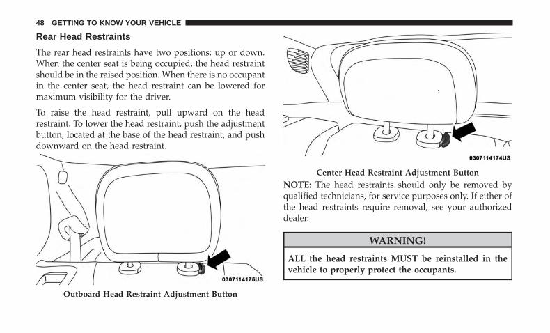
Rear Head Restraints
The rear head restraints have two positions: up or down.When the center seat is being occupied, the head restraintshould be in the raised position. When there is no occupantin the center seat, the head restraint can be lowered formaximum visibility for the driver.
To raise the head restraint, pull upward on the headrestraint. To lower the head restraint, push the adjustmentbutton, located at the base of the head restraint, and pushdownward on the head restraint.
NOTE: The head restraints should only be removed byqualified technicians, for service purposes only. If either ofthe head restraints require removal, see your authorizeddealer.
WARNING!
ALL the head restraints MUST be reinstalled in thevehicle to properly protect the occupants.
Outboard Head Restraint Adjustment Button
Center Head Restraint Adjustment Button
48 GETTING TO KNOW YOUR VEHICLE

STEERING WHEEL
Tilt/Telescoping Steering Column
This feature allows you to tilt the steering column upwardor downward. It also allows you to lengthen or shorten thesteering column. The tilt/telescoping lever is located belowthe steering wheel at the end of the steering column.
To unlock the steering column, push the control handledownward (toward the floor). To tilt the steering column,move the steering wheel upward or downward as desired.To lengthen or shorten the steering column, pull thesteering wheel outward or push it inward as desired. To
lock the steering column in position, push the controlhandle upward until fully engaged.
WARNING!
Do not adjust the steering column while driving.Adjusting the steering column while driving or driv-ing with the steering column unlocked, could cause thedriver to lose control of the vehicle. Failure to followthis warning may result in serious injury or death.
Heated Steering Wheel — If Equipped
The steering wheel contains a heating element that helpswarm your hands in cold weather. The heated steeringwheel has only one temperature setting. Once the heatedsteering wheel has been turned on, it can operate for anaverage of 80 minutes or more before automatically shut-ting off. This time may vary depending on environmentaltemperatures. The heated steering wheel can shut off earlyor may not turn on when the steering wheel is alreadywarm.
The heated steering wheel control button is located withinthe Uconnect system. You can gain access to the controlbutton through the climate screen or the controls screen.
Tilt/Telescoping Lever
3
GETTING TO KNOW YOUR VEHICLE 49

• Press the heated steering wheel button once to turnthe heating element on.
• Press the heated steering wheel button a second timeto turn the heating element off.
NOTE: The engine must be running for the heated steeringwheel to operate.
Vehicles With Remote Start — If Equipped
On models that are equipped with remote start, the heatedsteering wheel can be programmed to come on during aremote start through the Uconnect system. Refer to“Uconnect Settings” in “Multimedia” for further informa-tion.
WARNING!
• Persons who are unable to feel pain to the skinbecause of advanced age, chronic illness, diabetes,spinal cord injury, medication, alcohol use, exhaus-tion, or other physical conditions must exercise carewhen using the steering wheel heater. It may causeburns even at low temperatures, especially if usedfor long periods.
(Continued)
WARNING! (Continued)• Do not place anything on the steering wheel that
insulates against heat, such as a blanket or steeringwheel covers of any type and material. This maycause the steering wheel heater to overheat.
MIRRORS
Inside Day/Night Mirror — If Equipped
This is a single ball joint mirror that fixes to the windshieldbutton with a counter clockwise rotation. No tools areneeded for mounting. The mirror head can be adjusted leftand right, or tilted up and down for various drivers. Themirror should be adjusted to center on the view throughthe rear window.
50 GETTING TO KNOW YOUR VEHICLE

Headlight glare from vehicles behind you can be reducedby moving the small control under the mirror to the nightposition (toward the rear of the vehicle). The mirror shouldbe adjusted while set in the day position (toward thewindshield).
Electrochromic Mirror — If Equipped
This is a single ball joint mirror that fixes to the windshieldbutton with a counter clockwise rotation. No tools areneeded for mounting. The mirror head can be adjusted leftand right, or tilted up and down for various drivers. Themirror should be adjusted to center on the view throughthe rear window.
This mirror automatically adjusts for headlight glare fromvehicles behind you.
NOTE:
• The Electrochromic Mirror feature is disabled when thevehicle is in REVERSE to improve rear view viewing.
• The Electrochromic Mirror feature can be turned on oroff using the button located on the mirror. When theLED is on, the Automatic Dimming is enabled.
Adjusting Rearview Mirror
Automatic Dimming Button
3
GETTING TO KNOW YOUR VEHICLE 51

CAUTION!
To avoid damage to the mirror during cleaning, neverspray any cleaning solution directly onto the mirror.Apply the solution onto a clean cloth and wipe themirror clean.
Outside Mirrors
To receive maximum benefit, adjust the outside mirror(s) tocenter on the adjacent lane of traffic and a slight overlap ofthe view obtained from the inside mirror.
NOTE: The passenger side convex outside mirror will givea much wider view to the rear, and especially of the lanenext to your vehicle.
WARNING!
Vehicles and other objects seen in the passenger sideconvex mirror will look smaller and farther away thanthey really are. Relying too much on your passengerside convex mirror could cause you to collide withanother vehicle or other object. Use your inside mirrorwhen judging the size or distance of a vehicle seen inthe passenger side convex mirror.
Power Adjustment Mirrors
The power mirror switch is located on the driver’s doorpanel.
To adjust an exterior power mirror, select the right or leftside using the mirror selector switch, then push the mirroradjustment switch in the desired direction indicated by thedirection arrows.
52 GETTING TO KNOW YOUR VEHICLE

NOTE:
• To adjust the power mirrors, the ignition must be in theON/RUN position.
• Once the mirror is adjusted, rotate the control to theneutral position to avoid accidental movements.
Folding Mirrors
The exterior mirrors are hinged to allow the mirror to pivotforward or rearward to help avoid damage. The mirror hasthree detent positions: full forward, normal and full rear-ward.
Power Folding Mirror — If Equipped
The switch for the power folding mirrors is located in thepower mirror switch.
Push the switch once and the mirrors will fold in, pushingthe switch a second time will return the mirrors to thenormal driving position.
Power Mirror Switch
1 — Power Folding Mirror Switch2 — Mirror Selector Switch3 — Mirror Adjustment Switch
Folding Exterior Mirror
3
GETTING TO KNOW YOUR VEHICLE 53

Resetting The Power Folding Outside Mirrors
You may need to reset the power folding mirrors if thefollowing occurs:
• The mirrors are accidentally blocked while folding.
• The mirrors are accidentally manually folded/unfolded.
• The mirrors come out of the unfolded position.
• The mirrors shake and vibrate at normal driving speeds.
To reset the power folding mirrors: Fold and unfold themby pushing the button. (this may require multiple buttonpushes). This resets them to their normal position.
Puddle Lamps — If Equipped
Located under the exterior mirrors is a small lamp thatilluminates the ground when the doors are unlocked withthe key fob or when the doors to the vehicle are open.
Heated Mirrors — If Equipped
These mirrors are heated to melt frost or ice. Thisfeature will be activated whenever you turn on the
rear window defroster (if equipped). Refer to “ClimateControls” in this section for further information.
Illuminated Vanity Mirrors
An illuminated vanity mirror is located on each sun visor.To use the mirror, rotate the sun visor down and swing themirror cover upward. The lights will turn on automatically.Closing the mirror cover will turn off the light.
Illuminated Vanity Mirror Cover
54 GETTING TO KNOW YOUR VEHICLE

Sun Visor “Slide-On-Rod” Feature — If Equipped
The sun visor “Slide-On-Rod” feature allows for additionalflexibility in positioning the sun visor to block out the sun.
1. Fold down the sun visor.
2. Unclip the visor from the center clip.
3. Pivot the sun visor toward the side window.
4. Extend the sun visor blade for additional sun blockage.
NOTE: The sun visor blade can also be extended while thesun visor is against the windshield for additional sunblockage through the front of the vehicle.
EXTERIOR LIGHTS
Headlight Switch
The headlight switch is located on the left side ofthe instrument panel. This switch controls the op-eration of the headlights, parking lights, automatic
headlights — if equipped, instrument panel lights, instru-ment panel light dimming, interior lights and fog lights —if equipped.
Rotate the headlight switch clockwise to the first detent forparking light and instrument panel light operation. Rotatethe headlight switch to the second detent for headlight,parking light and instrument panel light operation.
Daytime Running Lights (DRL) — If Equipped
The Daytime Running Lights will turn on when the engineis started and remain on unless the headlamps are turnedon or the ignition is turned OFF.
Headlight Switch
3
GETTING TO KNOW YOUR VEHICLE 55

NOTE: If allowed by law in the country in which thevehicle was purchased the Daytime Running Lights can beturned on and off using the Uconnect System, refer to“Uconnect Settings” in “Multimedia” for further informa-tion.
Multifunction Lever
The multifunction lever controls the operation of the turnsignals, headlight beam selection and passing lights. Themultifunction lever is located on the left side of the steeringcolumn.
High/Low Beam Switch
Push the multifunction lever toward the instrument panelto switch the headlights to high beams. Pulling the multi-function lever back toward the steering wheel will returnthe lights to low beams.
Automatic High Beam Headlamp Control — IfEquipped
The Automatic High Beam Headlamp Control systemprovides increased forward lighting at night by automat-ing high beam control through the use of a digital cameramounted on the inside rearview mirror. This camera de-tects vehicle specific light and automatically switches fromhigh beams to low beams until the approaching vehicle isout of view.
NOTE:
• The Automatic High Beam Headlamp Control can beturned on or off using the Uconnect System. Refer to“Uconnect Settings” in “Multimedia” for further infor-mation.
Multifunction Lever
56 GETTING TO KNOW YOUR VEHICLE

• Broken, muddy, or obstructed headlights and taillightsof vehicles in the field of view will cause headlights toremain on longer (closer to the vehicle). Also, dirt, film,and other obstructions on the windshield or camera lenswill cause the system to function improperly.
• To opt out of the Advanced Auto High-Beam SensitivityControl (default) and enter Reduced High-Beam Sensi-tivity Control (not recommended), toggle highbeamlever 6 full on/off cycles within 10 seconds of ignitionON. System will return to default setting upon ignitionoff.
Flash-To-Pass
You can signal another vehicle with your headlights bylightly pulling the multifunction lever toward you. Thiswill cause the high beam headlights to turn on, and remainon, until the lever is released.
Automatic Headlights — If Equipped
This system automatically turns the headlights on or offaccording to ambient light levels. To turn the system on,rotate the headlight switch clockwise to the last detent forautomatic headlight operation. When the system is on, theheadlight time delay feature is also on. This means theheadlights will stay on for up to 90 seconds after you place
the ignition into the OFF position. To turn the automaticsystem off, move the headlight switch out of the AUTOposition.
NOTE: The engine must be running before the headlightswill come on in the automatic mode.
Headlight Time Delay
This feature provides the safety of headlight illuminationfor up to 90 seconds (programmable) when leaving yourvehicle in an unlit area.
To activate the delay feature, place the ignition in the OFFposition while the headlights are still on. Then, turn off theheadlights within 45 seconds. The delay interval beginswhen the headlight switch is turned off.
If you turn the headlights or parking lights on, or place theignition in ACC or RUN, the system will cancel the delay.
If you turn the headlights off before the ignition, they willturn off in the normal manner.
3
GETTING TO KNOW YOUR VEHICLE 57
NOTE:
• The lights must be turned off within 45 seconds ofplacing the ignition in the OFF position to activate thisfeature. If the headlight switch is in the AUTO positionprior to turning the ignition OFF, there is no need to turnthe headlight switch to off to activate Headlight Delay.
• The headlight delay time is programmable using theUconnect System, refer to “Uconnect Settings” in “Mul-timedia” for further information.
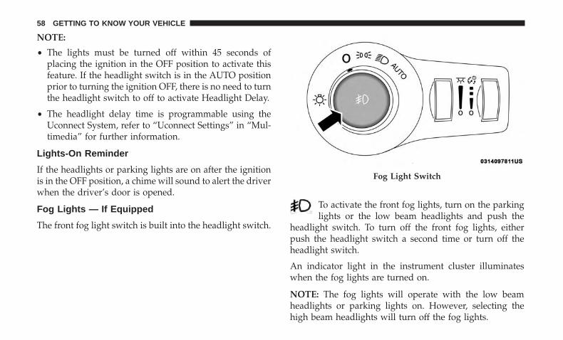
Lights-On Reminder
If the headlights or parking lights are on after the ignitionis in the OFF position, a chime will sound to alert the driverwhen the driver’s door is opened.
Fog Lights — If Equipped
The front fog light switch is built into the headlight switch.
To activate the front fog lights, turn on the parkinglights or the low beam headlights and push the
headlight switch. To turn off the front fog lights, eitherpush the headlight switch a second time or turn off theheadlight switch.
An indicator light in the instrument cluster illuminateswhen the fog lights are turned on.
NOTE: The fog lights will operate with the low beamheadlights or parking lights on. However, selecting thehigh beam headlights will turn off the fog lights.
Fog Light Switch
58 GETTING TO KNOW YOUR VEHICLE

Turn Signals
Move the multifunction lever up or down and the arrowson each side of the instrument cluster display flash to showproper operation of the front and rear turn signal lights.
NOTE:
• If either light remains on and does not flash, or there isa very fast flash rate, check for a defective outside lightbulb. If an indicator fails to light when the lever ismoved, it would suggest that the indicator bulb isdefective.
• A “Turn Signal On” message will appear in the instru-ment cluster display and a continuous chime will soundif the vehicle is driven more than 1 mile (1.6 km) witheither turn signal on.
• When the Daytime Running Lights are on and a turnsignal is activated, the Daytime Running Lamp will turnoff on the side of the vehicle in which the turn signal isflashing. The Daytime Running Lamp will turn back onwhen the turn signal is turned off.
Lane Change Assist
Tap the lever up or down once, without moving beyondthe detent, and the turn signal (right or left) will flash fivetimes then automatically turn off.
Battery Saver Feature
To protect the battery, the interior lights will turn offautomatically 15 minutes after the ignition switch is movedto the OFF/LOCK position. This will occur if the interiorlights were switched on manually or are on because a dooris open.
INTERIOR LIGHTS
Interior Courtesy Lights
The interior lights come on when a door is opened. Thelight switches in the overhead console are for readinglamps.
3
GETTING TO KNOW YOUR VEHICLE 59

To protect the battery, the interior lights will turn offautomatically 15 minutes after the ignition is moved to theLOCK position. This will occur if the interior lights wereswitched on manually or are on because a door is open.This includes the glove compartment light and the cargoarea light. To restore interior light operation, either placethe ignition in the ON/RUN position or cycle the lightswitch.
Instrument Panel Dimmer Control
The instrument panel dimmer control is part of the head-light switch and is located on the drivers side of theinstrument panel.
With the parking lights or headlights on, rotating theinstrument panel dimmer control upward will increase thebrightness of the instrument panel lights.
Ambient Light Control — If Equipped
Rotate the ambient dimmer control upward or downwardto increase or decrease the brightness of the ambient light
Overhead Light Switches
Instrument Panel Dimmer
60 GETTING TO KNOW YOUR VEHICLE

located in the overhead console, door handle lights, underI/P lights, door map pocket lights, and cubby bin lights.
WINDSHIELD WIPERS AND WASHERS
The windshield wiper/washer controls are located on thewindshield wiper/washer lever on the right side of thesteering column. The front wipers are operated by rotatinga switch, located on the end of the lever. For information onthe rear wiper/washer, refer to “Rear Wiper Operation” inthis section.
Windshield Wiper Operation
Rotate the end of the lever to one of the first two detentpositions for intermittent settings. The first intermittentwiper interval is 10 seconds. The second intermittent wipeinterval is based on vehicle speed. Rotate to the thirddetent for low wiper operation and the fourth detent forhigh wiper operation.
Ambient Light/Door Handle Light Dimmer
Windshield Wiper/Washer Lever
3
GETTING TO KNOW YOUR VEHICLE 61

CAUTION!
• Always remove any buildup of snow that preventsthe windshield wiper blades from returning to the“park” position. If the windshield wiper switch isturned off, and the blades cannot return to the “park”position, damage to the wiper motor may occur.
• Failure to follow these cautions can cause damage tothe heating elements:• Use care when washing the inside of the rear
window. Do not use abrasive window cleaners on
(Continued)
CAUTION! (Continued)the interior surface of the window. Use a soft clothand a mild washing solution, wiping parallel to theheating elements. Labels can be peeled off aftersoaking with warm water.
• Do not use scrapers, sharp instruments, or abrasivewindow cleaners on the interior surface of thewindow.
• Keep all objects a safe distance from the window.
Windshield Washer Operation
To use the washer, pull the lever toward you and holdwhile spray is desired. If the lever is pulled while in theintermittent setting, the wipers will turn on and operate forseveral wipe cycles after the lever is released, and thenresume the intermittent interval previously selected.
If the lever is pulled while the wipers are in the off position,the wipers will operate for several wipe cycles, then turn off.
WARNING!
Sudden loss of visibility through the windshield couldlead to a collision. You might not see other vehicles or
(Continued)
Windshield Wiper Operation
62 GETTING TO KNOW YOUR VEHICLE

WARNING! (Continued)other obstacles. To avoid sudden icing of the wind-shield during freezing weather, warm the windshieldwith the defroster before and during windshieldwasher use.
Mist
Use this feature when weather conditions make occasionalusage of the wipers necessary. Push the lever upward tothe MIST position and release for a single wiping cycle.
NOTE: The mist feature does not activate the washerpump; therefore, no washer fluid will be sprayed on thewindshield. The wash function must be used in order tospray the windshield with washer fluid.
Rain Sensing Wipers — If Equipped
This feature senses rain or snow fall on the windshield andautomatically activates the wipers for the driver. Thefeature is especially useful for road splash or oversprayfrom the windshield washers of the vehicle ahead. Rotatethe end of the multifunction lever to one of two settings toactivate this feature.
The sensitivity of the system can be adjusted with themultifunction lever. Wiper delay position one is the least
sensitive, and wiper delay position two is the most sensi-tive. Place the wiper switch in the O (off) position when notusing the system.
NOTE:
• The Rain Sensing feature will not operate when thewiper switch is in the low or high-speed position.
• The Rain Sensing feature may not function properlywhen ice, or dried salt water is present on the wind-shield.
• Use of Rain-X or products containing wax or siliconemay reduce Rain Sensing performance.
• The Rain Sensing feature can be turned on and off usingthe Uconnect System, refer to “Uconnect Settings” in“Multimedia” for further information.
The Rain Sensing system has protection features for thewiper blades and arms, and will not operate under thefollowing conditions:
• Change In Ignition Position — If the vehicle is in RainSensing mode and the ignition is cycled from OFF toON, the auto wiper will be suppressed until vehiclespeed is greater than 3 mph (5 km/h), or the wiperswitch is moved out of and back into the Intermittentwipe position.
3
GETTING TO KNOW YOUR VEHICLE 63

• Transmission In NEUTRAL Position — The Rain Sens-ing system will not operate if the NEUTRAL gear isselected in any speed unless the wiper switch is movedor the gear selector is moved out of NEUTRAL.
Remote Start Mode Inhibit — On vehicles equipped withRemote Starting system, Rain Sensing wipers are notoperational when the vehicle is in the remote start mode.Once the operator is in the vehicle and has placed theignition switch in the ON/RUN position, Rain Sensingwiper operation can resume, if it has been selected, and noother inhibit conditions (mentioned previously) exist.
Rear Window Wiper/Washer
The rear wiper/washer controls are located on the wind-shield wiper/washer lever on the right side of the steeringcolumn. The rear wiper has different operation modes:
• Intermittent mode
• In synchronous mode (at half speed of the front windowwiper) when the front window wiper is operating.
• Continuous mode
• Vehicle in REVERSE: If the front wiper is active and theREVERSE gear is selected, the wiper will turn on for onewipe.
Rotate the center portion of the lever upward to thefirst detent for intermittent operation and to the
second detent for continuous rear wiper operation.
To use the washer, push the lever forward andhold while spray is desired. If the lever is pushedwhile in the intermittent setting, the wiper willturn on and operate for several wipe cycles after
the end of the lever is released, and then resume theintermittent interval previously selected.
If the lever is pushed while the wiper is in the off position,the wiper will operate for several wipe cycles, then turn off.
NOTE: As a protective measure, the pump will stop if theswitch is held for more than 20 to 30 seconds. Once thelever is released the pump will resume normal operation.
Windshield Wiper De-Icer — If Equipped
Your vehicle may be equipped with a Windshield WiperDe-Icer feature that may be activated under the followingconditions:
• Activation By Front Defrost — The Windshield WiperDe-Icer shall be activated automatically in the case of acold weather manual start with full front defrost, andwhen the ambient temperature is below 33° F (0.6° C).
64 GETTING TO KNOW YOUR VEHICLE

• Activation By Rear Defrost — The Windshield WiperDe-Icer shall be activated automatically when the reardefrost is turned on and when the ambient temperatureis below 33° F (0.6° C).
• Activation By Remote Start Operation (If Equipped) —When remote start is active and the outside ambienttemperature is less than 33° F (0.6° C), the WindshieldWiper De-Icer shall be enabled. On exiting remote startresume previous operation except, if the WindshieldWiper De-Icer timer and operation shall continue.
CLIMATE CONTROLS
Climate Controls Without A Touchscreen Overview
The controls for the heating and air conditioning system inthis vehicle can consist of a series of outer rotary dials,
inner push knobs, and/or a touchscreen. These comfortcontrols can be set to obtain desired interior conditions.
Climate Controls Description
Icon DescriptionMAX A/C SettingSet the Temperature Control Knob to the MAX A/C Setting, to change the current setting to thecoldest output of air. Moving the Temperature Control Knob away from the MAX A/C settingcauses the MAX A/C operation to exit.
Manual Climate Controls
3
GETTING TO KNOW YOUR VEHICLE 65

Icon DescriptionA/C ButtonPress and release to change the current setting, the indicator illuminates when A/C is ON.
Recirculation ButtonPress and release this button to change the system between recirculation mode and outside airmode. Recirculation can be used when outside conditions such as smoke, odors, dust, or highhumidity are present.
NOTE:• Continuous use of the Recirculation mode may make the inside air stuffy and window fog-
ging may occur. Extended use of this mode is not recommended.• The use of the Recirculation mode in cold or damp weather could cause windows to fog on
the inside, because of moisture buildup inside the vehicle. Select the outside air position formaximum defogging.
• Recirculation can be used in all modes except for Defrost.• The A/C can be deselected manually without disturbing the mode control selection.Front Defrost SettingSet the Mode Control Knob to the Front Defroster Setting, to change the current airflow settingto Defrost mode. Air comes from the windshield and side window demist outlets when this fea-ture is on. When the defrost button is selected, the blower level may increase. Use Defrost modewith maximum temperature settings for best windshield and side window defrosting and de-fogging.
66 GETTING TO KNOW YOUR VEHICLE

Icon DescriptionRear Defrost ButtonPush and release the Rear Defrost Control button to turn ON the rear window defroster and theheated outside mirrors (if equipped). An indicator will illuminate when the rear window de-froster is on. The rear window defroster automatically turns off after ten minutes.Temperature Control KnobTemperature Control is used to regulate the temperature of the air forced through the climatesystem. The temperature can be selected using the temperature control knob on the faceplate.The temperature increases as you turn the temperature control knob clockwise. The temperaturedecreases as you turn the temperature control knob counterclockwise.Blower ControlBlower Control is used to regulate the amount of air forced through the climate system. Thereare seven blower speeds available. Adjusting the blower will cause automatic mode to switch tomanual operation. The speeds can be selected using the blower control knob on the faceplate.The blower speed increases as you turn the blower control knob clockwise from the lowestblower setting. The blower speed decreases as you turn the blower control knob counterclock-wise.
Panel Mode Panel ModeAir comes from the outlets in the instrument panel. Each of these outlets can be individuallyadjusted to direct the flow of air. The air vanes of the center outlets and outboard outlets can bemoved up and down or side to side to regulate airflow direction. There is a shut off wheel lo-cated below the air vanes to shut off or adjust the amount of airflow from these outlets.
3
GETTING TO KNOW YOUR VEHICLE 67
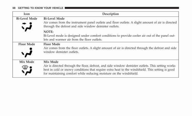
Icon DescriptionBi-Level Mode Bi-Level Mode
Air comes from the instrument panel outlets and floor outlets. A slight amount of air is directedthrough the defrost and side window demister outlets.
NOTE:Bi-Level mode is designed under comfort conditions to provide cooler air out of the panel out-lets and warmer air from the floor outlets.
Floor Mode Floor ModeAir comes from the floor outlets. A slight amount of air is directed through the defrost and sidewindow demister outlets.
Mix Mode Mix ModeAir is directed through the floor, defrost, and side window demister outlets. This setting worksbest in cold or snowy conditions that require extra heat to the windshield. This setting is goodfor maintaining comfort while reducing moisture on the windshield.
68 GETTING TO KNOW YOUR VEHICLE

Climate Controls With A Touchscreen Overview
The controls for the heating and air conditioning system inthis vehicle can consist of a series of outer rotary dials,inner push knobs, and/or a touchscreen. These comfortcontrols can be set to obtain desired interior conditions.
Uconnect 4 With 7-inch Display Automatic Climate Controls
3
GETTING TO KNOW YOUR VEHICLE 69

Climate Controls Description
Icon DescriptionMAX A/C ButtonPress and release the MAX A/C Button in the touchscreen to change the current setting to thecoldest output of air. Pressing the button again will cause the MAX A/C operation to exit.
Uconnect 4/4C NAV With 8.4-inch Display Automatic Climate Controls
70 GETTING TO KNOW YOUR VEHICLE

Icon DescriptionA/C ButtonPress and release to change the current setting, the indicator illuminates when A/C is ON.
Recirculation ButtonPress and release this button on the touchscreen or push the button on the faceplate to changethe system between recirculation mode and outside air mode.
NOTE:• Recirculation can be used when outside conditions, such as smoke, odors, dust or high hu-
midity are present.• Recirculation can be used on all modes except Defrost. The A/C can be deselected manually
without disturbing the mode control selection.• Continuous use of Recirculation mode may make the air inside the cabin stuffy and window
fogging may occur. Extended use is not recommended.AUTO ButtonAutomatically controls the interior cabin temperature by adjusting airflow distribution andamount. Toggling this function will cause the system to switch between manual mode and auto-matic modes. Refer to “Automatic Operation” within this section for more information.
3
GETTING TO KNOW YOUR VEHICLE 71

Icon DescriptionFront Defrost ButtonPress and release the Front Defrost Button to change the current airflow setting to Defrost mode.Air comes from the windshield and side window demist outlets when this feature is on. Whenthe defrost button is selected, the blower level may increase. Use Defrost mode with maximumtemperature settings for best windshield and side window defrosting and defogging. When tog-gling the front defrost mode button, the climate system will return to previous setting.Rear Defrost ButtonPush and release the Rear Defrost Control button to turn ON the rear window defroster and theheated outside mirrors (if equipped). An indicator will illuminate when the rear window de-froster is on. The rear window defroster automatically turns off after ten minutes.Driver and Passenger Temperature Up and Down ButtonsProvides the driver and passenger with independent temperature control. Push the red buttonon the faceplate or touchscreen or press and slide the temperature bar towards the red arrowbutton on the touchscreen for warmer temperature settings. Push the blue button on the face-plate or touchscreen or press and slide the temperature bar towards the blue arrow button onthe touchscreen for cooler temperature settings.
SYNC ButtonPress the SYNC button on the touchscreen (if equipped) or on the instrument panel (ifequipped) to toggle the Sync feature on/off. The SYNC indicator is illuminated when this fea-ture is enabled. SYNC is used to synchronize the passenger temperature setting with the drivertemperature setting. Changing the passenger temperature setting while in SYNC will automati-cally exit this feature.
72 GETTING TO KNOW YOUR VEHICLE
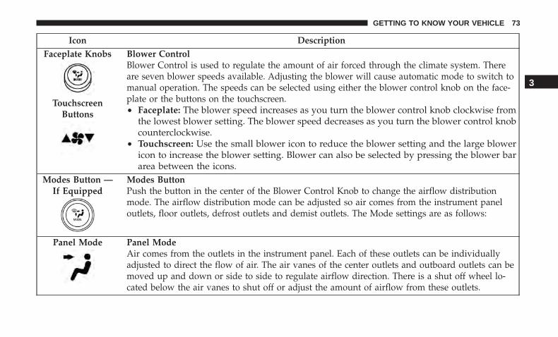
Icon DescriptionFaceplate Knobs
TouchscreenButtons
Blower ControlBlower Control is used to regulate the amount of air forced through the climate system. Thereare seven blower speeds available. Adjusting the blower will cause automatic mode to switch tomanual operation. The speeds can be selected using either the blower control knob on the face-plate or the buttons on the touchscreen.• Faceplate: The blower speed increases as you turn the blower control knob clockwise from
the lowest blower setting. The blower speed decreases as you turn the blower control knobcounterclockwise.
• Touchscreen: Use the small blower icon to reduce the blower setting and the large blowericon to increase the blower setting. Blower can also be selected by pressing the blower bararea between the icons.
Modes Button —If Equipped
Modes ButtonPush the button in the center of the Blower Control Knob to change the airflow distributionmode. The airflow distribution mode can be adjusted so air comes from the instrument paneloutlets, floor outlets, defrost outlets and demist outlets. The Mode settings are as follows:
Panel Mode Panel ModeAir comes from the outlets in the instrument panel. Each of these outlets can be individuallyadjusted to direct the flow of air. The air vanes of the center outlets and outboard outlets can bemoved up and down or side to side to regulate airflow direction. There is a shut off wheel lo-cated below the air vanes to shut off or adjust the amount of airflow from these outlets.
3
GETTING TO KNOW YOUR VEHICLE 73

Icon DescriptionBi-Level Mode Bi-Level Mode
Air comes from the instrument panel outlets and floor outlets. A slight amount of air is directedthrough the defrost and side window demister outlets.
NOTE:Bi-Level mode is designed under comfort conditions to provide cooler air out of the panel out-lets and warmer air from the floor outlets.
Floor Mode Floor ModeAir comes from the floor outlets. A slight amount of air is directed through the defrost and sidewindow demister outlets.
Mix Mode Mix ModeAir is directed through the floor, defrost, and side window demister outlets. This setting worksbest in cold or snowy conditions that require extra heat to the windshield. This setting is goodfor maintaining comfort while reducing moisture on the windshield.
Climate Control OFF ButtonPress and release this button to turn the Climate Controls off.
74 GETTING TO KNOW YOUR VEHICLE

Climate Control Functions
A/C (Air Conditioning)
The Air Conditioning (A/C) button allows the operator tomanually activate or deactivate the air conditioning sys-tem. When the air conditioning system is turned on, cooldehumidified air will flow through the outlets into thecabin. For improved fuel economy, press the A/C button toturn off the air conditioning and manually adjust theblower and airflow mode settings. Also, make sure to selectonly Panel, Bi-Level, or Floor modes.
NOTE:
• If fog or mist appears on the windshield or side glass,select Defrost mode and increase blower speed if needed.
• If your air conditioning performance seems lower thanexpected, check the front of the A/C condenser (locatedin front of the radiator), for an accumulation of dirt orinsects. Clean with a gentle water spray from the front ofthe radiator and through the condenser.
MAX A/C
MAX A/C sets the control for maximum cooling performance.Press and release to toggle between MAX A/C and the priorsettings. The button illuminates when MAX A/C is ON.
Pressing blower speed, temperature, recirculation, or modesettings, will cause the MAX A/C operation to switch tothe selected setting and MAX A/C to exit.
Recirculation
When outside air contains smoke, odors, or high humidity,or if rapid cooling is desired, you may wish to recirculateinterior air by pressing the Recirculation control button.The Recirculation indicator will illuminate when this but-ton is selected. Press the button a second time to turn offthe Recirculation mode and allow outside air into thevehicle.
NOTE: In cold weather, use of Recirculation mode maylead to excessive window fogging. The Recirculation fea-ture may be unavailable (button on the touchscreen greyedout) if conditions exist that could create fogging on theinside of the windshield.
Automatic Temperature Control (ATC) — IfEquipped
Automatic Operation
1. Push the AUTO button on the faceplate, or the AUTObutton on the touchscreen (if equipped) on the Auto-matic Temperature Control (ATC) Panel.
3
GETTING TO KNOW YOUR VEHICLE 75

2. Next, adjust the temperature you would like the systemto maintain by adjusting the temperature control but-tons. Once the desired temperature is displayed, thesystem achieves and automatically maintains that com-fort level.
3. When the system is set up for your comfort level, it isnot necessary to change the settings. You experience thegreatest efficiency by simply allowing the system tofunction automatically.
NOTE:
• It is not necessary to move the temperature settings forcold or hot vehicles. The system automatically adjuststhe temperature, mode, and blower speed to providecomfort as quickly as possible.
• The temperature can be displayed in U.S. or Metric unitsby selecting the US/Metric customer-programmable fea-ture.
To provide you with maximum comfort in the Automaticmode during cold start-ups, the blower fan remains on lowuntil the engine warms up. The blower increases in speedand transition into Auto mode.
Manual Operation Override
This system offers a full complement of manual overridefeatures. The AUTO symbol in the front ATC display willbe turned off when the system is being used in the manualmode.
Operating Tips
NOTE: Refer to the chart at the end of this section forsuggested control settings for various weather conditions.
Summer Operation
The engine cooling system must be protected with ahigh-quality antifreeze coolant to provide proper corrosionprotection and to protect against engine overheating. OATcoolant (conforming to MS.90032) is recommended.
Winter Operation
To ensure the best possible heater and defroster perfor-mance, make sure the engine cooling system is functioningproperly and the proper amount, type, and concentrationof coolant is used. Use of the Air Recirculation modeduring Winter months is not recommended, because it maycause window fogging.
76 GETTING TO KNOW YOUR VEHICLE

Vacation/Storage
Before you store your vehicle, or keep it out of service (i.e.,vacation) for two weeks or more, run the air conditioningsystem at idle for about five minutes, in fresh air with theblower setting on high. This will ensure adequate systemlubrication to minimize the possibility of compressor dam-age when the system is started again.
Window Fogging
Vehicle windows tend to fog on the inside in mild, rainy,and/or humid weather. To clear the windows, select De-frost or Mix mode and increase the front blower speed. Donot use the Recirculation mode without A/C for longperiods, as fogging may occur.
CAUTION!
Failure to follow these cautions can cause damage tothe heating elements:• Use care when washing the inside of the rear win-
dow. Do not use abrasive window cleaners on theinterior surface of the window. Use a soft cloth and amild washing solution, wiping parallel to the heat-
(Continued)
CAUTION! (Continued)ing elements. Labels can be peeled off after soakingwith warm water.
• Do not use scrapers, sharp instruments, or abrasivewindow cleaners on the interior surface of the win-dow.
• Keep all objects a safe distance from the window.
Outside Air Intake
Make sure the air intake, located directly in front of thewindshield, is free of obstructions, such as leaves. Leavescollected in the air intake may reduce airflow, and if theyenter the plenum, they could plug the water drains. InWinter months, make sure the air intake is clear of ice,slush, and snow.
Cabin Air Filter
The climate control system filters out dust and pollen fromthe air. Contact an authorized dealer to service your cabinair filter, and to have it replaced when needed.
3
GETTING TO KNOW YOUR VEHICLE 77

Operating Tips Chart WINDOWS
Power Window Controls
The window controls on the driver’s door control all thedoor windows.
There are single window controls on each passenger doortrim panel, which operate the passenger door windows.The window controls will operate only when the ignition isin the ACC or ON/RUN position.
Power Window Switches
78 GETTING TO KNOW YOUR VEHICLE

NOTE: For vehicles equipped with the Uconnect, thepower window switches will remain active for up to tenminutes after the ignition is cycled to the OFF position.Opening either front door will cancel this feature. The timeis programmable. Refer to “Uconnect Settings” in “Multi-media” for further information.
WARNING!
Never leave children unattended in a vehicle. Do notleave the key fob in or near the vehicle or in a locationaccessible to children, and do not leave the ignition ofa vehicle equipped with Keyless Enter-N-Go in theACC or ON/RUN mode. Occupants, particularly unat-tended children, can become entrapped by the win-dows while operating the power window switches.Such entrapment may result in serious injury or death.
Auto-Down Feature
The driver door power window switch and the passengerdoor power window switches have an Auto-Down feature.Push the window switch down, for a short period of time,and release and the window will go down automatically.
To open the window part way, push the window switchdown briefly and release it when you want the window tostop.
To stop the window from going all the way down duringthe Auto-Down operation, pull up on the switch briefly.
Auto-Up Feature With Anti-Pinch Protection
Lift the window switch up, for a short period of time, andrelease and the window will go up automatically.
To stop the window from going all the way up during theAuto-Up operation, push down on the switch briefly.
To close the window part way, lift the window switchbriefly and release it when you want the window to stop.
NOTE:
• If the window runs into any obstacle during auto-closure, it will reverse direction and then go back down.Remove the obstacle and use the window switch againto close the window.
• Any impact due to rough road conditions may triggerthe auto-reverse function unexpectedly during auto-closure. If this happens, pull the switch lightly and holdto close the window manually.
3
GETTING TO KNOW YOUR VEHICLE 79

WARNING!
There is no anti-pinch protection when the window isalmost closed. To avoid personal injury be sure to clearyour arms, hands, fingers and all objects from thewindow path before closing.
Reset Auto-Up
Should the Auto-Up feature stop working, the windowprobably needs to be reset. To reset Auto-Up:
1. Pull the window switch up to close the window com-pletely and continue to hold the switch up for anadditional two seconds after the window is closed.
2. Push the window switch down firmly to open thewindow completely and continue to hold the switchdown for an additional two seconds after the window isfully open.
Window Lockout Switch
The window lockout switch on the driver’s door trim panelallows you to disable the window controls on the rearpassenger doors. To disable the window controls, push andrelease the window lockout button (the indicator light onthe button with turn on). To enable the window controls,
push and release the window lockout button again (theindicator light on the button will turn back off).
Wind Buffeting
Wind buffeting can be described as the perception ofpressure on the ears or a helicopter-type sound in the ears.Your vehicle may exhibit wind buffeting with the windowsdown, or the sunroof (if equipped) in certain open orpartially open positions. This is a normal occurrence andcan be minimized. If the buffeting occurs with the rearwindows open, open the front and rear windows together
Window Lockout Switch
80 GETTING TO KNOW YOUR VEHICLE
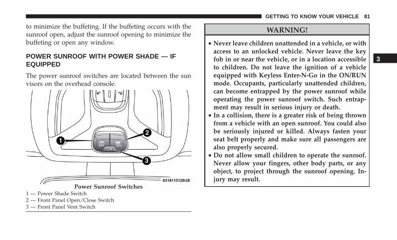
to minimize the buffeting. If the buffeting occurs with thesunroof open, adjust the sunroof opening to minimize thebuffeting or open any window.
POWER SUNROOF WITH POWER SHADE — IFEQUIPPED
The power sunroof switches are located between the sunvisors on the overhead console.
WARNING!
• Never leave children unattended in a vehicle, or withaccess to an unlocked vehicle. Never leave the keyfob in or near the vehicle, or in a location accessibleto children. Do not leave the ignition of a vehicleequipped with Keyless Enter-N-Go in the ON/RUNmode. Occupants, particularly unattended children,can become entrapped by the power sunroof whileoperating the power sunroof switch. Such entrap-ment may result in serious injury or death.
• In a collision, there is a greater risk of being thrownfrom a vehicle with an open sunroof. You could alsobe seriously injured or killed. Always fasten yourseat belt properly and make sure all passengers arealso properly secured.
• Do not allow small children to operate the sunroof.Never allow your fingers, other body parts, or anyobject, to project through the sunroof opening. In-jury may result.
Power Sunroof Switches1 — Power Shade Switch2 — Front Panel Open/Close Switch3 — Front Panel Vent Switch
3
GETTING TO KNOW YOUR VEHICLE 81

Opening Sunroof — Express
A comfort stop position and full open position are theprogrammed automatic stops for the sunroof open posi-tions. The comfort stop position has been optimized tominimize wind buffeting.
Push the switch and release it within one-half second. Thesunroof will open automatically to the comfort stop posi-tion (if the sunshade is in the closed position when theoperation is initiated the sunshade will automatically opento the half open position prior to the sunroof opening).Push the switch and release it again, the sunroof will opento the full open position and automatically stop. This iscalled “Express Open”. During Express Open operation,any movement of the sunroof switch will stop the sunroof.
Opening Sunroof — Manual Mode
A comfort stop position is a programmed automatic stopfor the sunroof open position. The comfort stop positionhas been optimized to minimize wind buffeting.
To open the sunroof, push and hold the switch. Thesunroof will stop automatically at the comfort stop position(if the sunshade is in the closed position when the opera-tion is initiated the sunshade will automatically open to thehalf open position prior to the sunroof opening). Push and
hold the switch again, the sunroof will open to the fullopen position and automatically stop. Any release of theswitch will stop the movement. The sunroof and sunshadewill remain in a partially opened condition until the switchis pushed and held again.
Closing Sunroof — Express
Pull the switch and release it within one-half second andthe sunroof will close automatically from any position. Thesunroof will close fully and stop automatically. This iscalled “Express Close.” During Express Close operation,any other actuation of the switch will stop the sunroof.
Closing Sunroof — Manual Mode
To close the sunroof, pull and hold the switch in the closeposition. Any release of the switch will stop the movementand the sunroof will remain in a partially closed conditionuntil the sunroof switch is pulled again.
Venting Sunroof — Express
Push and release the �Vent� button within one-half secondand the sunroof will move from the closed position to thevent position. This is called Express Vent. During ExpressVent operation, any movement of the switch will stop thesunroof.
82 GETTING TO KNOW YOUR VEHICLE

NOTE:
• If the sunshade is in the closed position when the ventswitch is pushed, the sunshade will automatically cycleto the halfway open position prior to the sunroof open-ing to the Vent position.
• When the sunroof is in a full open or a partial openposition, Express Vent operation is not available. Youmust push and hold the vent switch to cycle the sunrooffrom a slide open position to the vent position. Sunroofmovement will stop if the switch is released prior to thesunroof reaching the vent position.
Opening Power Shade — Express
Push the shade switch and release it within one-half secondand the shade will automatically open to the halfwayposition and stop automatically. Push the switch a secondtime from the halfway position and the shade will auto-matically open to the full open position and stop automati-cally. This is called “Express Open”. During Express Openoperation, any movement of the shade switch will stop theshade.
Opening Power Shade — Manual Mode
To open the shade, push and hold the switch. The shadewill open and stop automatically at the half-open position.
Push and hold the shade switch again and the shade willopen automatically to the full-open position. Any release ofthe switch will stop the movement and the shade willremain in a partially opened condition until the switch ispushed again.
Closing Power Shade — Express
Pull the switch and release it within one-half second andthe shade will close automatically from any position. If thesunroof is completely closed the shade will close fully andstop automatically. This is called “Express Close”. DuringExpress Close operation, any movement of the switch willstop the shade.
NOTE: If the sunroof is open, the shade will close to thehalf-open position. Pulling the shade close button againwill automatically close both the sunroof and shade com-pletely.
Closing Power Shade — Manual Mode
To close the shade, pull and hold the switch in the closeposition. Any release of the switch will stop the movementand the shade will remain in a partially closed conditionuntil the switch is pulled again.
3
GETTING TO KNOW YOUR VEHICLE 83

Pinch Protect Feature
This feature will detect an obstruction in the opening of thesunroof during Express Close operation. If an obstructionin the path of the sunroof is detected, the sunroof willautomatically retract. Remove the obstruction if this oc-curs. Next, pull the sunroof close switch and release toExpress Close.
NOTE: If three consecutive sunroof close attempts result inPinch Protect reversals, Pinch Protect will disable and thesunroof must be closed in Manual Mode.
Wind Buffeting
Wind buffeting can be described as the perception ofpressure on the ears or a helicopter-type sound in the ears.Your vehicle may exhibit wind buffeting with the windowsdown, or the sunroof (if equipped) in certain open orpartially open positions. This is a normal occurrence andcan be minimized. If the buffeting occurs with the rearwindows open, then open the front and rear windowstogether to minimize the buffeting. If the buffeting occurswith the sunroof open, adjust the sunroof opening tominimize the buffeting or open any window.
Sunroof Maintenance
Use only a non-abrasive cleaner and a soft cloth to clean theglass panel.
HOOD
Opening The Hood
Two latches must be released to open the hood.
1. Pull the hood release lever located underneath thedriver’s side of the instrument panel.
Hood Release Location (Underneath Instrument Panel)
84 GETTING TO KNOW YOUR VEHICLE

2. Move to the outside of the vehicle. The safety latchrelease lever is located behind the front edge of the hoodat the center. Reach in at the center of the hood with apalm facing the ground. Once contact is made with thesafety latch release lever, push it toward the passengerside of the vehicle to fully release the hood.
Closing The Hood
WARNING!
Be sure the hood is fully latched before driving yourvehicle. If the hood is not fully latched, it could openwhen the vehicle is in motion and block your vision.Failure to follow this warning could result in seriousinjury or death.
CAUTION!
To prevent possible damage, do not slam the hood toclose it. Lower hood to approximately 12 inches (30 cm)and drop the hood to close. Make sure hood is fullyclosed for both latches. Never drive vehicle unlesshood is fully closed, with both latches engaged.
Hood Safety Latch Release Lever Location
3
GETTING TO KNOW YOUR VEHICLE 85

LIFTGATE
Opening
To Unlock/Enter The Liftgate
The liftgate may be released by the overhead consoleswitch or the outside handle.
The overhead console switch will release the liftgate whenthe liftgate is unlocked or locked. The outside handlerequires the liftgate to be unlocked.
NOTE: Use the interior door lock/unlock button on thedoor panel or the key fob to lock and unlock the liftgate.The manual door locks on the doors and the exterior doorlock cylinder will not lock and unlock the liftgate.
WARNING!
Driving with the liftgate open can allow poisonousexhaust gases into your vehicle. You and your passen-gers could be injured by these fumes. Keep the liftgateclosed when you are operating the vehicle.
Closing
Grasp the liftgate pull handle and initiate lowering theliftgate. Release the handle when the liftgate reaches selfclosing position.
Liftgate Entry
86 GETTING TO KNOW YOUR VEHICLE

NOTE: Before closing the liftgate, make sure to be inpossession of the key because the liftgate may be locked.
Power Liftgate — If Equipped
The power liftgate may be opened or closed bythe key fob, outside handle, overhead consoleswitch, and the liftgate switch on the upper lefttrim when the liftgate is open.
Using any of the above ways:
• When the liftgate is fully closed, the liftgate will open.
• When the liftgate is fully open, the liftgate will close.
• When the liftgate is moving, the liftgate will reverse.
The key fob and the overhead console switch will open theliftgate when the liftgate is locked. The outside handlerequires the liftgate to be unlocked. Push the button on thekey fob twice within five seconds to open or close theliftgate.
When the liftgate button on the key fob is pushed twotimes, the turn signals will flash twice to signal that theliftgate is opening or closing (if Flash Lamps with Lock isenabled in the Uconnect settings), and the liftgate chimewill be audible. Refer to �Uconnect Settings� in �Multime-dia” for further information.
NOTE:
• Before closing the liftgate, make sure to be in possessionof the key because the liftgate may be locked.
• Use the interior door lock/unlock button on the doorpanel or the key fob to lock and unlock the liftgate. Themanual door locks on the doors and the exterior doorlock cylinder will not lock and unlock the liftgate.
Closing Liftgate
1 — Liftgate Pull Handle
3
GETTING TO KNOW YOUR VEHICLE 87

Lock The Vehicle
WARNING!
During power operation, personal injury or cargodamage may occur. Ensure the liftgate travel path isclear. Make sure the liftgate is closed and latchedbefore driving away.
NOTE:
• The liftgate will not power open or close if the gearselector is in gear or the vehicle speed is above 0 mph(0 km/h).
• If anything obstructs the power liftgate while it isclosing or opening, the liftgate will automatically re-verse to the closed or open position, provided it meetssufficient resistance.
• There are pinch sensors attached to the side of the liftgateopening. Light pressure anywhere along these strips willcause the liftgate to return to the open position.
• If the power liftgate encounters multiple obstructionswithin the same cycle, the system will automatically stop. Ifthis occurs, the liftgate must be opened or closed manually.
• The power liftgate will not operate in temperaturesbelow −22° F (−30° C) or temperatures about 150° F(65° C). Be sure to remove any buildup of snow or icefrom the liftgate before pushing any of the power liftgateswitches.
• If the liftgate is left open for an extended period of time,the liftgate may need to be closed manually to resetpower liftgate functionality.
• Gas props support the liftgate in the open position.However, because the gas pressure drops with tempera-ture, it may be necessary to assist the props whenopening the liftgate in cold weather.
• Before driving off, check the instrument cluster for aliftgate or door open message or warning indicator.Failure to do this could result in unintentionally leavingthe liftgate open while driving.
• If your liftgate is power closing and you put the vehiclein gear, the liftgate will continue to power close. How-ever, vehicle movement may result in a detection of anobstruction.
• If the electronic liftgate release handle is pushed with thepower liftgate is opening, the liftgate motor will disen-gage to allow manual operation.
88 GETTING TO KNOW YOUR VEHICLE

• If the electronic liftgate release handle is pushed whilethe power liftgate is closing, the liftgate will reverse tothe full open position.
WARNING!
• Driving with the liftgate open can allow poisonousexhaust gases into your vehicle. You and your pas-sengers could be injured by these fumes. Keep theliftgate closed when you are operating the vehicle.
• If you are required to drive with the liftgate open,make sure that all windows are closed, and theclimate control blower switch is set at high speed. Donot use the recirculation mode.
NOTE: Allow the power system to open the liftgate.Manually pushing or pulling the liftgate may activate theliftgate obstacle detection feature and stop the poweroperation or reverse its direction.
WARNING!
Personal injury or cargo damage may occur if caught inthe path of the liftgate. Make sure the liftgate path isclear before activating the liftgate.
Cargo Area Features
Cargo Load Floor
The cargo load floor system has a load capacity of 400 lbs(181 kg).
Cargo Load Floor Positions
The cargo load floor can be adjusted to three differentlevels to create more space in the cargo area. Thesepositions are: upper, center, and lower.
NOTE: The lower position is not available in vehiclesequipped with either a compact spare tire, or a full sizespare tire. The center position is not available in vehiclesequipped with a full size spare tire.
3
GETTING TO KNOW YOUR VEHICLE 89

To change the level of the load floor, pull upward on theload floor handle, pull the floor outward, and place theback of the floor into the desired position. Lower the frontof the floor into place.
Raising The Load Floor
To raise the load floor for access of the Tire Service Kit, orspare tire (if equipped), pull upward on the load floorhandle.
Do not raise the floor beyond the point of resistance. Invehicles equipped with a power liftgate, forcing the floorupward can damage the floor and vehicle’s trim panel.
To fully raise the load floor, pull upward on the floorhandle, pull the floor outward, then position the floorupright with the bottom fitting on top of the floor position-ing brackets. Push the top of the floor down firmly tosecure it in this position.
Cargo Load Floor Positions
1 — Upper Position2 — Center Position3 — Lower Position
Raised Load Floor — (Power Liftgate)
1 — Raised Load Floor2 — Raised Floor Maximum Height
90 GETTING TO KNOW YOUR VEHICLE

To provide additional storage area, each rear seat can befolded flat. This allows for extended cargo space and stillmaintains some rear seating room. Refer to “Seats” in“Getting To Know Your Vehicle” for further information.
Cargo Tie-Down Hooks And Loops
The tie-downs located on the cargo area floor should beused to secure loads safely when the vehicle is moving.
Cargo tie-down loops are located on the trim panels.
WARNING!
• Cargo tie-downs are not safe anchors for a child seattether strap. In a sudden stop or accident, a tie-downcould pull loose and allow the child seat to comeloose. A child could be badly injured. Use only theanchors provided for child seat tethers.
• To help protect against personal injury, passengersshould not be seated in the rear cargo area. The rearcargo space is intended for load carrying purposesonly, not for passengers, who should sit in seats anduse seat belts.
The weight and position of cargo and passengers canchange the vehicle center of gravity and vehicle han-dling. To avoid loss of control resulting in personalinjury, follow these guidelines for loading your vehicle:• Do not carry loads that exceed the load limits de-
scribed on the label attached to the left door or leftdoor center pillar.
• Always place cargo evenly on the cargo floor. Putheavier objects as low and as far forward as possible.
• Place as much cargo as possible in front of the rear axle.Too much weight or improperly placed weight over orbehind the rear axle can cause the vehicle to sway.
(Continued)
Fully Raised Load Floor Position
3
GETTING TO KNOW YOUR VEHICLE 91

WARNING! (Continued)• Do not pile luggage or cargo higher than the top of
the seatback. This could impair visibility or becomea dangerous projectile in a sudden stop or accident.
Rear Storage Bins
The rear storage bins are located in the rear of the vehicleon the sides of the load floor.
INTERNAL EQUIPMENT
Storage
Glove Compartment
The glove compartment is located on the passenger side ofthe instrument panel.
To open the glove compartment, pull the release handle.
Console Storage Compartment
To open, pull up on the latch and lift the cover.
Rear Storage Bin
Glove Compartment
92 GETTING TO KNOW YOUR VEHICLE

The center console armrest can also be adjusted forwardand rearward by pushing in the desired direction until itlocks into place.
The center console has a storage area which can hold cellphones, PDAs, and other small items.
WARNING!
Do not operate this vehicle with a console compartmentlid in the open position. Driving with the consolecompartment lid open may result in injury in a collision.
Cupholders
There are two cupholders for the front seat passengers,located in the center console.
There are two cupholders (if equipped) for the rear seatpassengers, located in the center armrest.
Power Outlets
Your vehicle is equipped with 12 Volt (13 Amp) poweroutlets that can be used to power cellular phones, smallelectronics and other low powered electrical accessories.The power outlets are labeled with either a “key” or a“battery” symbol to indicate how the outlet is powered.
Center Console Front Cupholders
3
GETTING TO KNOW YOUR VEHICLE 93

Power outlets labeled with a “key” are powered when theignition is in the ON or ACC position, while the outletslabeled with a “battery” are connected directly to thebattery and powered at all times.
NOTE:
• All accessories connected to the “battery” poweredoutlets should be removed or turned off when thevehicle is not in use to protect the battery againstdischarge.
CAUTION!
Power outlets are designed for accessory plugs only.Do not insert any other object in the power outlets asthis will damage the outlet and blow the fuse. Im-proper use of the power outlet can cause damage notcovered by your New Vehicle Limited Warranty.
The front power outlet is located on the center stack of theinstrument panel.
In addition to the front power outlet, there is may also bea power outlet located in the rear cargo area, if equipped.
Front Power Outlet
94 GETTING TO KNOW YOUR VEHICLE

NOTE: If equipped, the rear cargo area power outlet can beswitched from “ignition” only to constant “battery” pow-ered all the time. See an authorized dealer for details.
WARNING!
To avoid serious injury or death:• Only devices designed for use in this type of outlet
should be inserted into any 12 Volt outlet.• Do not touch with wet hands.
(Continued)
WARNING! (Continued)• Close the lid when not in use and while driving the
vehicle.• If this outlet is mishandled, it may cause an electric
shock and failure.
CAUTION!
• Many accessories that can be plugged in draw powerfrom the vehicle’s battery, even when not in use (i.e.,cellular phones, etc.). Eventually, if plugged in longenough, the vehicle’s battery will discharge suffi-ciently to degrade battery life and/or prevent theengine from starting.
• Accessories that draw higher power (i.e., coolers,vacuum cleaners, lights, etc.) will degrade the batteryeven more quickly. Only use these intermittently andwith greater caution.
• After the use of high power draw accessories, or longperiods of the vehicle not being started (with acces-sories still plugged in), the vehicle must be driven asufficient length of time to allow the generator torecharge the vehicle’s battery.
Rear Cargo Area Power Outlet
3
GETTING TO KNOW YOUR VEHICLE 95

Power Inverter — If Equipped
There is a 115 Volt, 150 Watt inverter outlet located on theback of the center console to convert DC current to ACcurrent. This outlet can power cellular phones, electronicsand other low power devices requiring power up to 150Watts. Certain high-end game consoles will exceed thispower limit, as will most power tools.
To turn on the power inverter outlet, simply plug in thedevice. The outlet automatically turns off when the deviceis unplugged.
The power inverter is designed with built-in overloadprotection. If the power rating of 150 Watts is exceeded, thepower inverter will automatically shut down. Once theelectrical device has been removed from the outlet theinverter should automatically reset. To avoid overloadingthe circuit, check the power ratings on electrical devicesprior to using the inverter.
WARNING!
To avoid serious injury or death:• Do not insert any objects into the receptacles.• Do not touch with wet hands.• Close the lid when not in use.• If this outlet is mishandled, it may cause an electric
shock and failure.
ROOF LUGGAGE RACK — IF EQUIPPED
The load carried on the roof, when equipped with aluggage rack, must not exceed 150 lbs (68 kg), and it shouldbe uniformly distributed over the cargo area.
Crossbars should always be used whenever cargo is placedon the roof rack. Check the straps frequently to be sure thatthe load remains securely attached.
Power Inverter Location
96 GETTING TO KNOW YOUR VEHICLE

NOTE: Crossbars can be purchased at your authorizeddealer through Mopar parts.
External racks do not increase the total load carryingcapacity of the vehicle. Be sure that the total occupant andluggage load inside the vehicle, plus the load on theluggage rack, do not exceed the maximum vehicle loadcapacity.
WARNING!
Cargo must be securely tied down before driving yourvehicle. Improperly secured loads can fly off the ve-hicle, particularly at high speeds, resulting in personalinjury or property damage. Follow the roof rack cau-tions when carrying cargo on your roof rack.
CAUTION!
• To avoid damage to the roof rack and vehicle, do notexceed the maximum roof rack load capacity. Alwaysdistribute heavy loads as evenly as possible andsecure the load appropriately.
(Continued)
CAUTION! (Continued)• Long loads, which extend over the windshield, such
as wood panels or surfboards, should be secured toboth the front and rear of the vehicle.
• Place a blanket or other protection between thesurface of the roof and the load.
• Travel at reduced speeds and turn corners carefullywhen carrying large or heavy loads on the roof rack.Wind forces, due to natural causes or nearby trucktraffic, can add sudden upward loads. This is espe-cially true on large flat loads and may result indamage to the cargo or your vehicle.
• Load should always be secured to cross bars first,with tie down loops used as additional securingpoints if needed. Tie loops are intended as supple-mentary tie down points only. Do not use ratchetingmechanisms with the tie loops. Check the strapsfrequently to be sure that the load remains securelyattached.
3
GETTING TO KNOW YOUR VEHICLE 97


GETTING TO KNOW YOUR INSTRUMENT PANEL
CONTENTS� INSTRUMENT CLUSTER . . . . . . . . . . . . . . . . . .100
▫ Instrument Cluster Descriptions . . . . . . . . . . . .101
� INSTRUMENT CLUSTER DISPLAY . . . . . . . . . . .102
▫ Instrument Cluster Display Location AndControls . . . . . . . . . . . . . . . . . . . . . . . . . . . . .103
▫ Oil Change Reset . . . . . . . . . . . . . . . . . . . . . .105
▫ Instrument Cluster Display Menu Items . . . . . .106
▫ Battery Saver On/Battery Saver ModeMessage — Electrical Load ReductionActions — If Equipped . . . . . . . . . . . . . . . . . .113
� TRIP COMPUTER . . . . . . . . . . . . . . . . . . . . . . .115
� WARNING LIGHTS AND MESSAGES . . . . . . . . .116
▫ Red Warning Lights . . . . . . . . . . . . . . . . . . . . .116
▫ Yellow Warning Lights . . . . . . . . . . . . . . . . . . .120
▫ Yellow Indicator Lights . . . . . . . . . . . . . . . . . . .125
▫ Green Indicator Lights . . . . . . . . . . . . . . . . . . .126
▫ White Indicator Lights . . . . . . . . . . . . . . . . . . .127
▫ Blue Indicator Lights . . . . . . . . . . . . . . . . . . . .129
▫ Gray Indicator Lights . . . . . . . . . . . . . . . . . . . .129
� ONBOARD DIAGNOSTIC SYSTEM — OBD II . . .129
▫ Onboard Diagnostic System (OBD II)Cybersecurity . . . . . . . . . . . . . . . . . . . . . . . . .130
� EMISSIONS INSPECTION AND MAINTENANCEPROGRAMS . . . . . . . . . . . . . . . . . . . . . . . . . . .130
4

INSTRUMENT CLUSTER
Base Instrument Cluster
100 GETTING TO KNOW YOUR INSTRUMENT PANEL

Instrument Cluster Descriptions
1. Tachometer• Indicates the engine speed in revolutions per minute
(RPM x 1000).
2. Instrument Cluster Display• The instrument cluster display features a driver-
interactive display. Refer to “Instrument Cluster Dis-
play” in “Getting To Know Your Instrument Panel” forfurther information.
3. Speedometer• Indicates vehicle speed.
4. Fuel Gauge• The gauge shows the level of fuel in the fuel tank when
the ignition switch is in the ON/RUN position.
Premium Instrument Cluster
4
GETTING TO KNOW YOUR INSTRUMENT PANEL 101

• The fuel pump symbol points to the side of thevehicle where the fuel door is located.
5. Temperature Gauge• The temperature gauge shows engine coolant tem-
perature. Any reading within the normal range indi-cates that the engine cooling system is operatingsatisfactorily.
• The gauge pointer will likely indicate a higher tem-perature when driving in hot weather or up mountaingrades. It should not be allowed to exceed the upperlimits of the normal operating range.
WARNING!
A hot engine cooling system is dangerous. You orothers could be badly burned by steam or boilingcoolant. You may want to call your authorized dealerfor service if your vehicle overheats.
CAUTION!
Driving with a hot engine cooling system could dam-age your vehicle. If the temperature gauge reads “H”
(Continued)
CAUTION! (Continued)pull over and stop the vehicle. Idle the vehicle with theair conditioner turned off until the pointer drops backinto the normal range. If the pointer remains on the“H”, turn the engine off immediately and call yourauthorized dealer for service.
NOTE: The hard telltales will illuminate for a bulb checkwhen the ignition is first cycled.
INSTRUMENT CLUSTER DISPLAY
Your vehicle may be equipped with an instrument clusterdisplay, which offers useful information to the driver. Withthe ignition in the STOP/OFF mode, opening/closing of adoor will activate the display for viewing, and display thetotal miles, or kilometers, in the odometer. Your instrumentcluster display is designed to display important informa-tion about your vehicle’s systems and features. Using adriver interactive display located on the instrument panel,your instrument cluster display can show you how sys-tems are working and give you warnings when they aren’t.The steering wheel mounted controls allow you to scroll
102 GETTING TO KNOW YOUR INSTRUMENT PANEL

through and enter the main menus and submenus. You canaccess the specific information you want and make selec-tions and adjustments.
Instrument Cluster Display Location And Controls
The instrument cluster display features a driver-interactivedisplay that is located in the instrument cluster.
The instrument cluster display menu items consist of thefollowing as equipped:
• Speedometer
• Vehicle Info
• Driver Assist
• Fuel Economy
• Trip
• Stop/Start (If Equipped)
Base Instrument Cluster Display Location And Controls
Premium Instrument Cluster Display Location AndControls
4
GETTING TO KNOW YOUR INSTRUMENT PANEL 103
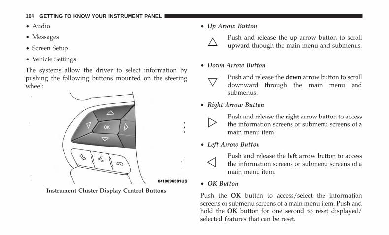
• Audio
• Messages
• Screen Setup
• Vehicle Settings
The systems allow the driver to select information bypushing the following buttons mounted on the steeringwheel:
• Up Arrow Button
Push and release the up arrow button to scrollupward through the main menu and submenus.
• Down Arrow Button
Push and release the down arrow button to scrolldownward through the main menu andsubmenus.
• Right Arrow Button
Push and release the right arrow button to accessthe information screens or submenu screens of amain menu item.
• Left Arrow Button
Push and release the left arrow button to accessthe information screens or submenu screens of amain menu item.
• OK Button
Push the OK button to access/select the informationscreens or submenu screens of a main menu item. Push andhold the OK button for one second to reset displayed/selected features that can be reset.
Instrument Cluster Display Control Buttons
104 GETTING TO KNOW YOUR INSTRUMENT PANEL

Oil Change Reset
• Your vehicle is equipped with an engine oil changeindicator system. The “Oil Change Due” message willdisplay in the instrument cluster display for five secondsafter a single chime has sounded, to indicate the nextscheduled oil change interval. The engine oil changeindicator system is duty cycle based, which means theengine oil change interval may fluctuate, dependentupon your personal driving style.
• Unless reset, this message will continue to display eachtime the ignition is cycled to the ON/RUN position.
• To reset the oil change indicator after performing thescheduled maintenance, refer to the following proce-dure.
Models Equipped With Keyless Enter-N-Go — Ignition
1. Without pushing the brake pedal, push the ENGINESTART/STOP button and cycle the ignition to the ON/RUN position (do not start the engine).
2. Fully push the accelerator pedal, slowly, three timeswithin ten seconds.
3. Cycle the ignition to the OFF/LOCK position.
NOTE: If the indicator message illuminates when youstart the vehicle, the oil change indicator system did notreset. If necessary, repeat this procedure.
Push Button Ignition
4
GETTING TO KNOW YOUR INSTRUMENT PANEL 105
Instrument Cluster Display Menu Items
NOTE: The instrument cluster display menu items displayin the center of the instrument cluster. Menu items mayvary depending on your vehicle features.
Speedometer
Push and release the up or down arrow button until theSpeedometer Menu item is displayed in the instrumentcluster display. Push and release the OK button to changethe speedometer scale from MPH to km/h (or vice versa).
Vehicle Info (Customer Information Features)
Push and release the up or down arrow button until theVehicle Info Menu item is displayed in the instrumentcluster display. Push and release the left or right arrowbutton to cycle through the Vehicle Info submenus andfollow the prompts on each screen as needed.
1. Tire Pressure• If tire pressure is OK for all tires a vehicle ICON is
displayed with tire pressure values in each corner ofthe ICON.
• If one or more tires have low pressure, “Inflate Tire ToXX” is displayed with the vehicle ICON and the tire
pressure values in each corner of the ICON with thepressure value of the low tire displayed in a differentcolor than the other tire pressure value.
• If the Tire Pressure system requires service, “ServiceTire Pressure System” is displayed.
• Tire PSI is an information only function and cannot bereset.
• Refer to “Tire Pressure Monitoring System (TPMS)”under “Safety” for further information.
2. Coolant Temperature
Displays the actual coolant temperature.
3. Transmission Temperature — Automatic TransmissionOnly
Displays the actual transmission temperature.
4. Oil Temperature
Displays the level of oil temperature.
5. Battery Voltage
Displays the actual battery voltage
106 GETTING TO KNOW YOUR INSTRUMENT PANEL

Fuel Economy
Push and release the up or down arrow button until theFuel Economy menu title is displayed in the instrumentcluster display. Push and hold the OK button to resetaverage fuel economy feature.
• Range – The display shows the estimated distance (mior km) that can be traveled with the fuel remaining inthe tank. When the Range value is less than 30 miles(48 km) estimated driving distance, the Range displaywill change to a “LOW FUEL” message. Adding asignificant amount of fuel to the vehicle will turn off the“LOW FUEL” message and a new Range value willdisplay. Range cannot be reset through the OK button.
NOTE: Significant changes in driving style or vehicleloading will greatly affect the actual drivable distance ofthe vehicle, regardless of the Range displayed value.
• Average – This display shows the average fuel economy(MPG, or L/100 km, or km/L) since the last reset.
• Current – This display shows the current fuel economy(MPG, or L/100 km, or km/L) while driving.
Driver Assist
Push and release the up or down arrow button until theDriver Assist menu title is displayed is highlighted in theinstrument cluster display.
LaneSense — If Equipped
The instrument cluster display displays the current Lane-Sense system settings. The information displayed dependson LaneSense system status and the conditions that need tobe met. Refer to “LaneSense — If Equipped” in “StartingAnd Operating” for further information.
Trip Info
Push and release the up or down arrow button until theTrip menu title is displayed in the instrument clusterdisplay. Toggle the left or right arrow button to select TripA or Trip B. The Trip information will display the follow-ing:
• Distance – Shows the total distance (mi or km) traveledfor Trip A or Trip B since the last reset.
• Average Fuel Economy – Shows the average fueleconomy (MPG or L/100 km or km/L) of Trip A or TripB since the last reset.
4
GETTING TO KNOW YOUR INSTRUMENT PANEL 107

• Elapsed Time – Shows the total elapsed time of travelsince Trip A or Trip B has been reset.
Hold the OK button to reset feature information.
Stop/Start – If Equipped
Push and release the up or down arrow button until theStop/Start menu title is displayed in the instrument clusterdisplay.
Audio
Push and release the up or down arrow button until theAudio menu title is displayed in the instrument clusterdisplay.
Stored Messages
Push and release the up or down arrow button until theMessages Menu Icon is highlighted in the instrumentcluster display. This feature shows the number of storedwarning messages. Pushing the left or right arrow buttonwill allow you to scroll through the stored messages.
Screen Setup
Push and release the up or down arrow button until theScreen Setup Menu Icon/Title is highlighted in the instru-ment cluster display. Push and release the OK button to
enter the sub-menus and follow the prompts on the screenas needed. The Screen Setup feature allows you to changewhat information is displayed in the instrument cluster aswell as the location that information is displayed.
Screen Setup Driver Selectable Items
Upper Left
• None
• Compass (default setting)
• Outside Temp
• Date
• Time
• Ignition State
• Range
• Fuel Economy Average — Premium Cluster
• Fuel Economy Current — Premium Cluster
Upper Right
• None
• Compass
• Outside Temp
108 GETTING TO KNOW YOUR INSTRUMENT PANEL

• Date
• Time
• Ignition State (default setting)
• Range
• Fuel Economy Average — Premium Cluster
• Fuel Economy Current — Premium Cluster
Restore Defaults (Restores All Settings To Default Set-tings)
• Yes
• No
Current Gear — If Equipped
• On
• Off (default setting)
Center
• None
• Compass
• Menu Title (default setting)
• Date
• Outside Temp
• Time
• Range
• Fuel Economy Average
• Fuel Economy Current
• Audio Info
• Trip A Distance
• Trip B Distance
• Speedometer
Vehicle Settings — If Equipped
Push and release the up or down arrow button until theVehicle Setup Menu item is displayed in the instrumentcluster display. This menu item allows you to change thesettings for the following:
• Display
• Units
• Clock and Date
• Security
• Safety and Assistance
4
GETTING TO KNOW YOUR INSTRUMENT PANEL 109

• Lights
• Doors and Locks
• Compass — If Equipped
NOTE: Most vehicle settings will be moved into the radioif a touchscreen radio is present, please refer to “UconnectSettings” in “Multimedia” for further information.
Display
By selecting Display, the following settings can be selected:
• Language: select the language in which to display theinformation/warnings.
• Nav. Repetition: displays information relating to thenavigation mode.
Units
By selecting Units, the unit of measurement to use fordisplaying various values can be set. Possible options are:
• US
• Metric
• Custom: allows individual changes of units for tempera-ture, distance, consumption, and tire pressure.
Clock And Date
By selecting Clock and Date, the time and date can be set.Possible options are:
• Set Time: adjust hours/minutes
• Set Format: adjust the time format “12h” (12 hours) or“24h” (24 hours)
• Set Date: adjust day/month/year
Security
Passenger Air Bag Disable (PAD): a selection of PassengerAir Bag Disable (ON/OFF) may be made if a child restraintmust be installed in the front seat.
Safety And Assistance
By selecting the item Safety and Assistance, the followingadjustments can be made:
• ParkSense (If Equipped): a selection of the type ofinformation provided by ParkSense
• Front ParkSense Volume (If Equipped): selection of thevolume of the beeps provided by the front ParkSense
• Rear ParkSense Volume (If Equipped): selection of thevolume of the beeps provided by the rear ParkSense
110 GETTING TO KNOW YOUR INSTRUMENT PANEL

• FCW Warning (If Equipped): a selection of operatingmodes of the system Forward Collision Warning Plus
• FCW Sensitivity (If Equipped): a selection of the “readi-ness” of intervention of the Forward Collision WarningPlus system, based on the distance to the obstacle
• Rain Sensing Wipers (If Equipped): enabling/disablingthe automatic operation of wipers in the event of rain
• LaneSense Force (If Equipped): selection of the force tobe applied to the steering wheel to put the car in theroadway through the system of electrical drive, in caseof operation of the system LaneSense
• LaneSense Warning (If Equipped): a selection of the“readiness” of intervention of LaneSense
• Buzzer Volume: There are 4 options: Off, Low, Medium,Loud
• Brake Service (If Equipped): activation of the procedureto carry out braking system maintenance
• Auto Park Brake (If Equipped): enable/disable autoinsertion of the Electric Parking Brake
• Speed Warning: Set the vehicle speed limit, which thedriver is notified through a visual and acoustic signaling(display of a message and a symbol on the display).When the speed warning is set, the icon (a circle with theset speed inside of it) should remain visualized until thedriver turns the Speed Warning off. If the driver ex-ceeded the set speed, the icon should remain for how-ever long the vehicle is over the set speed. Driver mayalso turn the Speed Warning “OFF” in the InstrumentCluster Display should you choose not to use thisfeature. To turn the feature off, the driver must use theInstrument Cluster Display buttons to navigate to theSpeed Warning, and then press the up or down arrowuntil you reach “OFF” rather than a speed.
• Hill Start Assist: Activation/Deactivation of the HillStart Assist system
Lights
By selecting Lights, the following adjustments can bemade:
• Ambient Lights (If Equipped): adjust the sensitivity oflighting in the doors and overhead console
4
GETTING TO KNOW YOUR INSTRUMENT PANEL 111

• Lights Off Delay: set the delay for headlight shutoff afterengine shutoff
• Headlight Sensitivity: adjust the sensitivity of headlightbrightness
• Greeting Lights: activate the direction indicators whenunlocking the doors
• Daytime Lights (If Equipped): activate/deactivate thedaytime running lights
• Cornering Lights (If Equipped): activate/deactivate thecornering lights
• Auto High Beam (If Equipped): activate/deactivate theautomatic high beam headlights
Doors And Locks
By selecting Doors and Locks, the following adjustmentscan be made:
• Auto Lock Doors: activate/deactivate the automaticlocking of the doors with the vehicle moving
• Auto Unlock Doors: automatic unlocking of the doorswhen exiting the vehicle
• Lights with Lock: activate the direction indicators whenlocking the doors
• Horn With Remote Lock: activate/deactivate the hornwhen pressing the lock button on the key. The optionsare “Off”, “First Press”, and “Second Press”
• Horn With Remote Start (If Equipped): activate/deactivate the horn at the Remote Starting of the enginewith the key
• Door Unlock: allow you to choose whether to unlock allthe doors or only the driver’s side door on the first pushof the unlock button on the key
• Auto Driver Comfort (If Equipped): activate/deactivateautomatic climate control during vehicle starts
• Key in Memory (If Equipped): activate/deactivatememory linked to a key
Compass
By selecting Compass, the following settings can bechanged:
Calibration (If Equipped)
This compass is self-calibrating, which eliminates the needto set the compass manually. When the vehicle is new, thecompass may appear erratic, and the cluster will displaydashes (- -) until the compass is calibrated. You may alsocalibrate the compass by completing one or more 360
112 GETTING TO KNOW YOUR INSTRUMENT PANEL

degree turns (in an area free from large metal or metallicobjects) until the dashes (- -) displayed in the instrumentcluster display turns off. The compass will now functionnormally.
Variance (If Equipped)
Compass Variance is the difference between MagneticNorth and Geographic North. To compensate for thedifferences, the variance should be set for the zone wherethe vehicle is driven, per the zone map. Once properly set,the compass will automatically compensate for the differ-ences and provide the most accurate compass heading.
Battery Saver On/Battery Saver Mode Message —Electrical Load Reduction Actions — If Equipped
This vehicle is equipped with an Intelligent Battery Sensor(IBS) to perform additional monitoring of the electricalsystem and status of the vehicle battery.
In cases when the IBS detects charging system failure, orthe vehicle battery conditions are deteriorating, electricalload reduction actions will take place to extend the drivingtime and distance of the vehicle. This is done by reducingpower to or turning off non-essential electrical loads.
Load reduction is only active when the engine is running.It will display a message if there is a risk of batterydepletion to the point where the vehicle may stall due tolack of electrical supply, or will not restart after the currentdrive cycle.
When load reduction is activated, the message “BatterySaver On” or “Battery Saver Mode” will appear in theinstrument cluster display.
These messages indicate the vehicle battery has a low stateof charge and continues to lose electrical charge at a ratethat the charging system cannot sustain.
Compass Variance Map
4
GETTING TO KNOW YOUR INSTRUMENT PANEL 113

NOTE:
• The charging system is independent from load reduc-tion. The charging system performs a diagnostic on thecharging system continuously.
• If the Battery Charge Warning Light is on it may indicatea problem with the charging system. Refer to “BatteryCharge Warning Light” in “Warning And IndicatorLights And Messages” located in ”Getting To KnowYour Instrument Panel” for further information.
The electrical loads that may be switched off (if equipped),and vehicle functions which can be effected by loadreduction:
• Heated Seat/Vented Seats/Heated Wheel
• Heated/Cooled Cup Holders — If Equipped
• Rear Defroster And Heated Mirrors
• HVAC System
• 150W Power Inverter System
• Audio and Telematics System
Loss of the battery charge may indicate one or more of thefollowing conditions:
• The charging system cannot deliver enough electricalpower to the vehicle system because the electrical loadsare larger than the capability of charging system. Thecharging system is still functioning properly.
• Turning on all possible vehicle electrical loads (e.g.HVAC to max settings, exterior and interior lights,overloaded power outlets +12V, 150W, USB ports) dur-ing certain driving conditions (city driving, towing,frequent stopping).
• Installing options like additional lights, upfitter electricalaccessories, audio systems, alarms and similar devices.
• Unusual driving cycles (short trips separated by longparking periods).
• The vehicle was parked for an extended period of time(weeks, months).
• The battery was recently replaced and was not chargedcompletely.
• The battery was discharged by an electrical load left onwhen the vehicle was parked.
114 GETTING TO KNOW YOUR INSTRUMENT PANEL

• The battery was used for an extended period with theengine not running to supply radio, lights, chargers,+12V portable appliances like vacuum cleaner’s, gameconsoles and similar devices.
What to do when an electrical load reduction actionmessage is present (“Battery Saver On” or “Battery SaverMode”)
During a trip:
• Reduce power to unnecessary loads if possible:– Turn off redundant lights (interior or exterior)– Check what may be plugged in to power outlets +12V,
150W, USB ports– Check HVAC settings (blower, temperature)– Check the audio settings (volume)
After a trip:
• Check if any aftermarket equipment was installed (ad-ditional lights, upfitter electrical accessories, audio sys-tems, alarms) and review specifications if any (load andIgnition Off Draw currents).
• Evaluate the latest driving cycles (distance, driving timeand parking time).
• The vehicle should have service performed if the mes-sage is still present during consecutive trips and theevaluation of the vehicle and driving pattern did nothelp to identify the cause.
TRIP COMPUTER
Push and release the up or down arrow button until theTrip A or Trip B icon is highlighted in the instrumentcluster display (Toggle left or right to select Trip A orTrip B). Push and release the OK button to display the Tripinformation.
Trip A
• Shows the total distance traveled for Trip A since the lastreset.
• Shows the elapsed time traveled for Trip A since the lastreset.
Trip B
• Shows the total distance traveled for Trip B since the lastreset.
• Shows the elapsed time traveled for Trip B since the lastreset.
4
GETTING TO KNOW YOUR INSTRUMENT PANEL 115

Elapsed Time
Shows the total elapsed time of travel since the last resetwhen the ignition switch is in the ACC position. Elapsedtime will increment when the ignition switch is in the ONor START position.
To Reset A Trip Function
Reset will only occur while a resettable function is selected(highlighted). Push and hold the OK button to clear theresettable function being displayed.
WARNING LIGHTS AND MESSAGES
The warning/indicator lights will illuminate in the instru-ment panel together with a dedicated message and/oracoustic signal when applicable. These indications areindicative and precautionary and as such must not beconsidered as exhaustive and/or alternative to the infor-mation contained in the Owner’s Manual, which you areadvised to read carefully in all cases. Always refer to theinformation in this chapter in the event of a failure indica-tion. All active telltales will display first if applicable. Thesystem check menu may appear different based uponequipment options and current vehicle status. Some tell-tales are optional and may not appear.
Red Warning Lights
— Air Bag Warning Light
This light indicates a fault with the air bag, and will turn onfor four to eight seconds as a bulb check when the ignitionis placed in the ON/RUN or ACC/ON/RUN position.This light will illuminate with a single chime when a faultwith the air bag has been detected, it will stay on until thefault is cleared. If the light is either not on during startup,stays on, or turns on while driving, have the systeminspected at an authorized dealer as soon as possible.
— Brake Warning Light
This light monitors various brake functions, includingbrake fluid level and parking brake application. If thebrake light turns on it may indicate that the parking brakeis applied, that the brake fluid level is low, or that there isa problem with the anti-lock brake system reservoir.
If the light remains on when the parking brake has beendisengaged, and the fluid level is at the full mark on themaster cylinder reservoir, it indicates a possible brakehydraulic system malfunction or that a problem with theBrake Booster has been detected by the Anti-Lock BrakeSystem (ABS) / Electronic Stability Control (ESC) system.In this case, the light will remain on until the condition has
116 GETTING TO KNOW YOUR INSTRUMENT PANEL

been corrected. If the problem is related to the brakebooster, the ABS pump will run when applying the brake,and a brake pedal pulsation may be felt during each stop.
The dual brake system provides a reserve braking capacityin the event of a failure to a portion of the hydraulicsystem. A leak in either half of the dual brake system isindicated by the Brake Warning Light, which will turn onwhen the brake fluid level in the master cylinder hasdropped below a specified level.
The light will remain on until the cause is corrected.
NOTE: The light may flash momentarily during sharpcornering maneuvers, which change fluid level conditions.The vehicle should have service performed, and the brakefluid level checked.
If brake failure is indicated, immediate repair is necessary.
WARNING!
Driving a vehicle with the red brake light on isdangerous. Part of the brake system may have failed. Itwill take longer to stop the vehicle. You could have acollision. Have the vehicle checked immediately.
Vehicles equipped with the Anti-Lock Brake System (ABS)are also equipped with Electronic Brake Force Distribution(EBD). In the event of an EBD failure, the Brake WarningLight will turn on along with the ABS Light. Immediaterepair to the ABS system is required.
Operation of the Brake Warning Light can be checked byturning the ignition switch from the OFF position to theON/RUN position. The light should illuminate for ap-proximately two seconds. The light should then turn offunless the parking brake is applied or a brake fault isdetected. If the light does not illuminate, have the lightinspected by your authorized dealer.
The light also will turn on when the parking brake isapplied with the ignition switch in the ON/RUN position.
NOTE: This light shows only that the parking brake isapplied. It does not show the degree of brake application.
— Battery Charge Warning Light
This light illuminates when the battery is not chargingproperly. If it stays on while the engine is running, theremay be a malfunction with the charging system. Contactyour authorized dealer as soon as possible.
This indicates a possible problem with the electrical systemor a related component.
4
GETTING TO KNOW YOUR INSTRUMENT PANEL 117

— Door Open Warning Light
This indicator will illuminate when a door is ajar/open andnot fully closed.
NOTE: If the vehicle is moving, there will also be a singlechime.
— Electric Power Steering Fault Warning Light
This light will turn on when there’s a fault with the EPS(Electric Power Steering) system. Refer to “Power Steering”in “Starting And Operating” for further information.
WARNING!
Continued operation with reduced assist could pose asafety risk to yourself and others. Service should beobtained as soon as possible.
— Electronic Throttle Control (ETC) WarningLight
This light informs you of a problem with the ElectronicThrottle Control (ETC) system. If a problem is detectedwhile the vehicle is running, the light will either stay on orflash depending on the nature of the problem. Cycle theignition when the vehicle is safely and completely stoppedand the transmission is placed in the PARK position. The
light should turn off. If the light remains on with thevehicle running, your vehicle will usually be drivable;however, see an authorized dealer for service as soon aspossible.
NOTE: This light may turn on if the accelerator and brakepedals are pressed at the same time.
If the light continues to flash when the vehicle is running,immediate service is required and you may experiencereduced performance, an elevated/rough idle, or enginestall and your vehicle may require towing. The light willcome on when the ignition is placed in the ON/RUN orACC/ON/RUN position and remain on briefly as a bulbcheck. If the light does not come on during starting, havethe system checked by an authorized dealer.
— Engine Coolant Temperature Warning Light
This light warns of an overheated engine condition. If theengine coolant temperature is too high, this indicator willilluminate and a single chime will sound. If the tempera-ture reaches the upper limit, a continuous chime will besound for four minutes or until the engine is able to cool:whichever comes first.
If the light turns on while driving, safely pull over and stopthe vehicle. If the A/C system is on, turn it off. Also, shift
118 GETTING TO KNOW YOUR INSTRUMENT PANEL
the transmission into NEUTRAL and idle the vehicle. If thetemperature reading does not return to normal, turn theengine off immediately and call for service. Refer to “IfYour Engine Overheats” in “In Case Of Emergency” forfurther information.
— Hood Open Warning Light
This indicator will illuminate when the hood is left openand not fully closed.
NOTE: If the vehicle is moving, there will also be a singlechime.
— Liftgate Open Warning Light
This indicator light will illuminate when the liftgate isopen.
NOTE: If the vehicle is moving, there will also be a singlechime.
— Oil Pressure Warning Light
This warning light will illuminate to indicate low engineoil pressure. If the light turns on while driving, stop thevehicle and shut off the engine as soon as possible. A chimewill sound when this light turns on.
Do not operate the vehicle until the cause is corrected. Thislight does not indicate how much oil is in the engine. Theengine oil level must be checked under the hood.
— Oil Temperature Warning Light
This telltale indicates engine oil temperature is high. If thelight turns on while driving, stop the vehicle and shut offthe engine as soon as possible. Wait for oil temperature toreturn to normal levels.
— Seat Belt Reminder Warning Light
This light indicates when the driver or passenger seat beltis unbuckled. When the ignition is first placed in theON/RUN or ACC/ON/RUN position and if the driver’sseat belt is unbuckled, a chime will sound and the light willturn on. When driving, if the driver or front passenger seatbelt remains unbuckled, the Seat Belt Reminder Light willflash or remain on continuously and a chime will sound.Refer to “Occupant Restraint Systems” in “Safety” forfurther information.
— Transmission Fault Warning Light
This light will illuminate (together with a message in theinstrument cluster display and a buzzer) to indicate atransmission fault. Contact your authorized dealer if themessage remains after restarting the engine.
4
GETTING TO KNOW YOUR INSTRUMENT PANEL 119
— Transmission Temperature Warning Light — IfEquipped
This light indicates high transmission fluid temperature.This may occur with strenuous usage such as trailertowing. If this light turns on, stop the vehicle and run theengine at idle or slightly faster, with the transmission inPARK or NEUTRAL, until the light turns off. Once the lightturns off, you may continue to drive normally.
WARNING!
If you continue operating the vehicle when the Trans-mission Temperature Warning Light is illuminated youcould cause the fluid to boil over, come in contact withhot engine or exhaust components and cause a fire.
CAUTION!
Continuous driving with the Transmission Tempera-ture Warning Light illuminated will eventually causesevere transmission damage or transmission failure.
— Vehicle Security Warning Light — If Equipped
This light will flash at a fast rate for approximately 15seconds when the vehicle security alarm is arming, andthen will flash slowly until the vehicle is disarmed.
Yellow Warning Lights
— Anti-Lock Brake (ABS) Warning Light
This light monitors the Anti-Lock Brake System (ABS). Thelight will turn on when the ignition is placed in theON/RUN or ACC/ON/RUN position and may stay on foras long as four seconds.
If the ABS light remains on or turns on while driving, thenthe Anti-Lock portion of the brake system is not function-ing and service is required as soon as possible. However,the conventional brake system will continue to operatenormally, assuming the Brake Warning Light is not also on.
If the ABS light does not turn on when the ignition isplaced in the ON/RUN or ACC/ON/RUN position, havethe brake system inspected by an authorized dealer.
— Electronic Park Brake Warning Light
This telltale will turn on to indicate the Electronic ParkBrake is not functioning properly and service is required.Contact an authorized dealer.
120 GETTING TO KNOW YOUR INSTRUMENT PANEL

— Electronic Stability Control (ESC) ActiveWarning Light — If Equipped
This warning light will indicate when the Electronic Sta-bility Control system is Active. The “ESC Indicator Light”in the instrument cluster will come on when the ignition isplaced in the ON/RUN or ACC/ON/RUN position, andwhen ESC is activated. It should go out with the enginerunning. If the “ESC Indicator Light” comes on continu-ously with the engine running, a malfunction has beendetected in the ESC system. If this warning light remainson after several ignition cycles, and the vehicle has beendriven several miles (kilometers) at speeds greater than30 mph (48 km/h), see an authorized dealer as soon aspossible to have the problem diagnosed and corrected.
• The “ESC Off Indicator Light” and the “ESC IndicatorLight” come on momentarily each time the ignition isplaced in the ON/RUN or ACC/ON/RUN position.
• The ESC system will make buzzing or clicking soundswhen it is active. This is normal; the sounds will stopwhen ESC becomes inactive.
• This light will come on when the vehicle is in an ESCevent.
— Electronic Stability Control (ESC) Off WarningLight — If Equipped
This warning light indicates the Electronic Stability Control(ESC) is off.
Each time the ignition is turned to ON/RUN or ACC/ON/RUN, the ESC system will be on, even if it was turned offpreviously.
— Fuel Cutoff Warning Light — If Equipped
This telltale will illuminate after an accident has occurred,and the system has shut the fuel off.
— LaneSense Warning Light — If Equipped
The LaneSense Warning Light will be solid yellow whenthe vehicle is approaching a lane marker. The warning lightwill flash when the vehicle is crossing the lane marker.
Refer to “LaneSense — If Equipped� in “Starting AndOperating” for further information.
— Service LaneSense Warning Light — IfEquipped
This light will turn on when the LaneSense system is notoperating and needs service. Please see an authorizeddealer.
4
GETTING TO KNOW YOUR INSTRUMENT PANEL 121

— Low Coolant Level Warning Light
This telltale will turn on to indicate the vehicle coolantlevel is low.
— Low Fuel Warning Light
Depending on whether the tank size is 51L or 60L, the LowFuel Indicator Light will turn on when the fuel level goesbelow 1.5 gal (5.6L) or 1.7 gal (6.6L) respectively.
— Low Washer Fluid Warning Light — IfEquipped
This indicator will illuminate when the windshield washerfluid is low.
— Engine Check/Malfunction Indicator WarningLight (MIL)
The Engine Check/Malfunction Indicator Light (MIL) is apart of an Onboard Diagnostic System called OBD II thatmonitors engine and automatic transmission control sys-tems. This warning light will illuminate when the ignitionis in the ON/RUN position before engine start. If the bulbdoes not come on when turning the ignition switch fromOFF to ON/RUN, have the condition checked promptly.
Certain conditions, such as a loose or missing gas cap, poorquality fuel, etc., may illuminate the light after engine start.
The vehicle should be serviced if the light stays on throughseveral typical driving styles. In most situations, the ve-hicle will drive normally and will not require towing.
When the engine is running, the MIL may flash to alertserious conditions that could lead to immediate loss ofpower or severe catalytic converter damage. The vehicleshould be serviced as soon as possible if this occurs.
WARNING!
A malfunctioning catalytic converter, as referencedabove, can reach higher temperatures than in normaloperating conditions. This can cause a fire if you driveslowly or park over flammable substances such as dryplants, wood, cardboard, etc. This could result in deathor serious injury to the driver, occupants or others.
CAUTION!
Prolonged driving with the Malfunction IndicatorLight (MIL) on could cause damage to the vehiclecontrol system. It also could affect fuel economy anddriveability. If the MIL is flashing, severe catalyticconverter damage and power loss will soon occur.Immediate service is required.
122 GETTING TO KNOW YOUR INSTRUMENT PANEL

— Service 4WD Warning Light — If Equipped
If the light stays on or comes on during driving, it meansthat the 4WD system is not functioning properly and thatservice is required. We recommend you drive to the nearestservice center and have the vehicle serviced immediately.
— Service Forward Collision Warning (FCW)Light — If Equipped
This telltale will turn on to indicate a fault in the ForwardCollision Warning System. Contact your local authorizeddealer for service. Refer to �Forward Collision Warning(FCW)� in �Safety� for further information.
— Service Stop/Start System Warning Light — IfEquipped
This telltale will turn on to indicate the Stop/Start systemis not functioning properly and service is required. Contactyour authorized dealer for service.
— Tire Pressure Monitoring System (TPMS)Warning Light
The warning light switches on and a message is displayedto indicate that the tire pressure is lower than the recom-mended value and/or that slow pressure loss is occurring.
In these cases, optimal tire duration and fuel consumptionmay not be guaranteed.
Should one or more tires be in the condition mentionedabove, the display will show the indications correspondingto each tire in sequence.
CAUTION!
Do not continue driving with one or more flat tires ashandling may be compromised. Stop the vehicle,avoiding sharp braking and steering. If a tire punctureoccurs, repair immediately using the dedicated tirerepair kit and contact your authorized dealer as soon aspossible.
Each tire, including the spare (if provided), should bechecked monthly when cold and inflated to the inflationpressure recommended by the vehicle manufacturer on thevehicle placard or tire inflation pressure label. (If yourvehicle has tires of a different size than the size indicatedon the vehicle placard or tire inflation pressure label, youshould determine the proper tire inflation pressure forthose tires.)
As an added safety feature, your vehicle has beenequipped with a tire pressure monitoring system (TPMS)
4
GETTING TO KNOW YOUR INSTRUMENT PANEL 123

that illuminates a low tire pressure telltale when one ormore of your tires is significantly under-inflated. Accord-ingly, when the low tire pressure telltale illuminates, youshould stop and check your tires as soon as possible, andinflate them to the proper pressure. Driving on a signifi-cantly under-inflated tire causes the tire to overheat andcan lead to tire failure. Under-inflation also reduces fuelefficiency and tire tread life, and may affect the vehicle’shandling and stopping ability.
Please note that the TPMS is not a substitute for proper tiremaintenance, and it is the driver’s responsibility to main-tain correct tire pressure, even if under-inflation has notreached the level to trigger illumination of the TPMS lowtire pressure telltale.
Your vehicle has also been equipped with a TPMS malfunc-tion indicator to indicate when the system is not operatingproperly. The TPMS malfunction indicator is combinedwith the low tire pressure telltale. When the system detectsa malfunction, the telltale will flash for approximately oneminute and then remain continuously illuminated. Thissequence will continue upon subsequent vehicle start-upsas long as the malfunction exists. When the malfunctionindicator is illuminated, the system may not be able todetect or signal low tire pressure as intended. TPMS
malfunctions may occur for a variety of reasons, includingthe installation of replacement or alternate tires or wheelson the vehicle that prevent the TPMS from functioningproperly. Always check the TPMS malfunction telltale afterreplacing one or more tires or wheels on your vehicle toensure that the replacement or alternate tires and wheelsallow the TPMS to continue to function properly.
CAUTION!
The TPMS has been optimized for the original equip-ment tires and wheels. TPMS pressures and warninghave been established for the tire size equipped onyour vehicle. Undesirable system operation or sensordamage may result when using replacement equip-ment that is not of the same size, type, and/or style.Aftermarket wheels can cause sensor damage. Usingaftermarket tire sealants may cause the Tire PressureMonitoring System (TPMS) sensor to become inoper-able. After using an aftermarket tire sealant it isrecommended that you take your vehicle to your au-thorized dealer to have your sensor function checked.
124 GETTING TO KNOW YOUR INSTRUMENT PANEL

— Towing Hook Breakdown Warning Light — IfEquipped
This light illuminates when there is a failure with the towhook. Contact your authorized dealer for service.
Yellow Indicator Lights
— 4WD Low Indicator Light — If Equipped
This light alerts the driver that the vehicle is in thefour-wheel drive LOW mode. The front and rear drive-shafts are mechanically locked together forcing the frontand rear wheels to rotate at the same speed. Low rangeprovides a greater gear reduction ratio to provide increasedtorque at the wheels.
Refer to “Four-Wheel Drive Operation — If Equipped” in“Starting And Operating” for further information on four-wheel drive operation and proper use.
— 4WD Lock Indicator Light
This light alerts the driver that the vehicle is in thefour-wheel drive LOCK mode. The front and rear drive-shafts are mechanically locked together, forcing the frontand rear wheels to rotate at the same speed.
Refer to “Four-Wheel Drive Operation” in “Starting AndOperating” for further information on four-wheel driveoperation and proper use.
— Active Speed Limiter Fault Indicator Light —If Equipped
This light will turn on when there is a fault detected withthe Active Speed Limiter.
— Electronic Stability Control (ESC) IndicatorLight
The “ESC Indicator Light” in the instrument cluster willcome on when the ignition is placed in the ON/RUNposition. It should go out when the engine is running. If the“ESC Indicator Light” comes on continuously with theengine running, a malfunction has been detected in theESC system. If this light remains on after several ignitioncycles, and the vehicle has been driven several miles(kilometers) at speeds greater than 30 mph (48 km/h), seeyour authorized dealer as soon as possible to have theproblem diagnosed and corrected.
• The “ESC Off Indicator Light” and the “ESC IndicatorLight” come on momentarily each time the ignition isplaced in the ON/RUN position.
4
GETTING TO KNOW YOUR INSTRUMENT PANEL 125

• Each time the ignition is placed in the ON/RUN posi-tion, the ESC system will be ON, even if it was turned offpreviously.
• The ESC system will make buzzing or clicking soundswhen it is active. This is normal; the sounds will stopwhen ESC becomes inactive following the maneuverthat caused the ESC activation.
This telltale indicates that an ESC event is active.
— Electronic Stability Control (ESC) OFFIndicator Light — If Equipped
This light indicates the Electronic Stability Control (ESC) isoff.
— Forward Collision Indicator Light — IfEquipped
This telltale will turn on to warn you of a possible collisionwith the vehicle in front of you.
— Forward Collision Warning Off Indicator Light— If Equipped
This light indicates that Forward Collision Warning is off.
— Immobilizer Fail / VPS Electrical AlarmIndicator Light
This telltale will illuminate when the vehicle security alarmsystem has detected an attempt to break into the vehicle.
Green Indicator Lights
— Active Speed Limiter SET Indicator Light — IfEquipped With A Premium Instrument Cluster
This indicator light will illuminate when the Active SpeedLimiter is on and set to a specific speed.
— LaneSense Indicator Light — If Equipped
The LaneSense indicator is solid green when both lanemarkings have been detected and the system is “armed”and ready to provide visual and torque warnings if anunintentional lane departure occurs. Refer to “LaneSense— If Equipped� in “Starting And Operating” for furtherinformation.
— Park/Headlight On Indicator Light
This indicator light will illuminate when the park lights orheadlights are turned on.
126 GETTING TO KNOW YOUR INSTRUMENT PANEL

— Front Fog Indicator Light — If Equipped
This indicator will illuminate when the front fog lights areon.
— Turn Signal Indicator Lights
When the left or right turn signal is activated, the turnsignal indicator will flash independently and the corre-sponding exterior turn signal lamps will flash. Turn signalscan be activated when the multifunction lever is moveddown (left) or up (right).
NOTE:
• A continuous chime will sound if the vehicle is drivenmore than 1 mile (1.6 km) with either turn signal on.
• Check for an inoperative outside light bulb if eitherindicator flashes at a rapid rate.
— Cruise Control SET Indicator Light — IfEquipped With A Premium Instrument Cluster
This indicator light will illuminate when the speed controlis set to the desired speed. Refer to “Speed Control — IfEquipped” in “Starting And Operating” for further infor-mation.
— Stop/Start Active Indicator Light — IfEquipped
This indicator light will illuminate when the Stop/Startfunction is in “Autostop” mode.
— Automatic High Beam Indicator Light — IfEquipped
This indicator shows that the automatic high beam head-lights are on.
White Indicator Lights
— Active Speed Limiter Ready Indicator Light —If Equipped With A Premium Instrument Cluster
This light will illuminate when the Active Speed Limiterhas been turned on, but not set.
— Active Speed Limiter SET Indicator Light — IfEquipped With A Base Instrument Cluster
This light will turn on when the Active Speed Limiter is onand set to a specific speed.
— Cruise Control Ready Indicator
This light will turn on when the speed control is ready, butnot set.
4
GETTING TO KNOW YOUR INSTRUMENT PANEL 127

— LaneSense Indicator Light — If Equipped
When the LaneSense system is ON, but not armed, theLaneSense indicator is solid white. This occurs when onlyleft, right, or neither lane line has been detected. If a singlelane line is detected, the system is ready to provide onlyvisual warnings if an unintentional lane departure occurson the detected lane line.
Refer to “LaneSense — If Equipped� in “Starting AndOperating” for further information.
— Hill Descent Control (HDC) Indicator Light —If Equipped
This indicator shows when the Hill Descent Control (HDC)feature is turned on. The lamp will be on solid when HDCis armed. HDC can only be armed when the transfer case isin the “4WD LOW” position and the vehicle speed is lessthen 30 mph (48 km/h). If these conditions are not metwhile attempting to use the HDC feature, the HDC indi-cator light will flash on/off.
— Cruise Control Ready Indicator Light — IfEquipped With A Premium Instrument Cluster
This light will turn on when the speed control has beenturned on, but not set. Refer to “Speed Control — IfEquipped” in “Starting And Operating” for further infor-mation.
— Cruise Control SET Indicator Light — IfEquipped With Base Instrument Cluster
This indicator light will illuminate when the speed controlis set.
Refer to “Speed Control — If Equipped” in “Starting AndOperating” for further information.
— Speed Warning Indicator Light — If Equipped
When Set Speed Warning is turned on and when the setspeed is exceeded, a single chime will sound along withpop up message of “Speed Warning Exceeded.” SpeedWarning can be turned on and off in the instrument clusterdisplay.
Refer to “Instrument Cluster Display Menu Items” in“Getting To Know Your Instrument Panel” for furtherinformation.
128 GETTING TO KNOW YOUR INSTRUMENT PANEL

The number “55” is only an example of a speed that can beset.
Blue Indicator Lights
— High Beam Indicator Light
This indicator shows that the high beam headlights are on.With the low beams activated, push the multifunction leverforward (toward the front of the vehicle) to turn on thehigh beams. Pull the multifunction lever rearward (towardthe rear of the vehicle) to turn off the high beams. If thehigh beams are off, pull the lever toward you for atemporary high beam on, �flash to pass� scenario.
Gray Indicator Lights
— Cruise Control Ready Indicator Light — IfEquipped With Base Instrument Cluster
This light will turn on when the speed control has beenturned on, but not set. Refer to “Speed Control — IfEquipped” in “Starting And Operating” for further infor-mation.
— Active Speed Limiter Ready Indicator Light —If Equipped With A Base Instrument Cluster
This light will turn on when the Active Speed Limiter is on,but not set.
ONBOARD DIAGNOSTIC SYSTEM — OBD II
Your vehicle is equipped with a sophisticated OnboardDiagnostic system called OBD II. This system monitors theperformance of the emissions, engine, and automatic trans-mission control systems. When these systems are operatingproperly, your vehicle will provide excellent performanceand fuel economy, as well as emissions well within currentgovernment regulations.
If any of these systems require service, the OBD II systemwill turn on the Malfunction Indicator Light (MIL). It willalso store diagnostic codes and other information to assistyour service technician in making repairs. Although yourvehicle will usually be drivable and not need towing, seean authorized dealer for service as soon as possible.
4
GETTING TO KNOW YOUR INSTRUMENT PANEL 129

CAUTION!
• Prolonged driving with the MIL on could causefurther damage to the emission control system. Itcould also affect fuel economy and driveability. Thevehicle must be serviced before any emissions testscan be performed.
• If the MIL is flashing while the vehicle is running,severe catalytic converter damage and power losswill soon occur. Immediate service is required.
Onboard Diagnostic System (OBD II) Cybersecurity
Your vehicle is required to have an Onboard Diagnosticsystem (OBD II) and a connection port to allow access toinformation related to the performance of your emissionscontrols. Authorized service technicians may need to ac-cess this information to assist with the diagnosis andservice of your vehicle and emissions system.
WARNING!
• ONLY an authorized service technician should con-nect equipment to the OBD II connection port inorder to diagnose or service your vehicle.
(Continued)
WARNING! (Continued)• If unauthorized equipment is connected to the OBD
II connection port, such as a driver-behavior trackingdevice, it may:• Be possible that vehicle systems, including safety
related systems, could be impaired or a loss ofvehicle control could occur that may result in anaccident involving serious injury or death.
• Access, or allow others to access, informationstored in your vehicle systems, including personalinformation.
For further information, refer to “Cybersecurity” in “Mul-timedia”.
EMISSIONS INSPECTION AND MAINTENANCEPROGRAMS
In some localities, it may be a legal requirement to pass aninspection of your vehicle’s emissions control system.Failure to pass could prevent vehicle registration.
130 GETTING TO KNOW YOUR INSTRUMENT PANEL

For states that require an Inspection and Main-tenance (I/M), this check verifies the “Malfunc-tion Indicator Light (MIL)” is functioning and isnot on when the engine is running, and that the
OBD II system is ready for testing.
Normally, the OBD II system will be ready. The OBD IIsystem may not be ready if your vehicle was recentlyserviced, recently had a dead battery or a battery replace-ment. If the OBD II system should be determined not readyfor the I/M test, your vehicle may fail the test.
Your vehicle has a simple ignition actuated test, which youcan use prior to going to the test station. To check if yourvehicle’s OBD II system is ready, you must do the following:
1. Cycle the ignition switch to the ON position, but do notcrank or start the engine.
NOTE: If you crank or start the engine, you will have tostart this test over.
2. As soon as you cycle the ignition switch to the ONposition, you will see the “Malfunction Indicator Light(MIL)” symbol come on as part of a normal bulb check.
3. Approximately 15 seconds later, one of two things willhappen:
• The MIL will flash for about ten seconds and then returnto being fully illuminated until you turn OFF the igni-tion or start the engine. This means that your vehicle’sOBD II system is not ready and you should not proceedto the I/M station.
• The MIL will not flash at all and will remain fullyilluminated until you place the ignition in the off posi-tion or start the engine. This means that your vehicle’sOBD II system is ready and you can proceed to the I/Mstation.
If your OBD II system is not ready, you should see anauthorized dealer or repair facility. If your vehicle wasrecently serviced or had a battery failure or replacement,you may need to do nothing more than drive your vehicleas you normally would in order for your OBD II system toupdate. A recheck with the above test routine may thenindicate that the system is now ready.
Regardless of whether your vehicle’s OBD II system is readyor not, if the MIL is illuminated during normal vehicleoperation you should have your vehicle serviced beforegoing to the I/M station. The I/M station can fail yourvehicle because the MIL is on with the engine running.
4
GETTING TO KNOW YOUR INSTRUMENT PANEL 131


SAFETY
CONTENTS� SAFETY FEATURES . . . . . . . . . . . . . . . . . . . . . .134
▫ Anti-Lock Brake System (ABS) . . . . . . . . . . . . .134
▫ Electronic Brake Control System . . . . . . . . . . . .135
� AUXILIARY DRIVING SYSTEMS . . . . . . . . . . . . .146
▫ Blind Spot Monitoring (BSM) — If Equipped . . .146
▫ Forward Collision Warning (FCW) WithMitigation — If Equipped . . . . . . . . . . . . . . . .154
▫ Tire Pressure Monitor System (TPMS) . . . . . . . .157
� OCCUPANT RESTRAINT SYSTEMS . . . . . . . . . .165
▫ Occupant Restraint Systems Features . . . . . . . .165
▫ Important Safety Precautions . . . . . . . . . . . . . .165
▫ Seat Belt Systems . . . . . . . . . . . . . . . . . . . . . .166
▫ Supplemental Restraint Systems (SRS) . . . . . . . .179
▫ Child Restraints . . . . . . . . . . . . . . . . . . . . . . .200
▫ Transporting Pets . . . . . . . . . . . . . . . . . . . . . .215
� SAFETY TIPS . . . . . . . . . . . . . . . . . . . . . . . . . . .215
▫ Transporting Passengers . . . . . . . . . . . . . . . . . .215
▫ Exhaust Gas . . . . . . . . . . . . . . . . . . . . . . . . . .216
▫ Safety Checks You Should Make Inside TheVehicle . . . . . . . . . . . . . . . . . . . . . . . . . . . . . .216
▫ Periodic Safety Checks You Should MakeOutside The Vehicle . . . . . . . . . . . . . . . . . . . .218
5

SAFETY FEATURES
Anti-Lock Brake System (ABS)
The Anti-Lock Brake System (ABS) provides increasedvehicle stability and brake performance under most brak-ing conditions. The system automatically prevents wheellock, and enhances vehicle control during braking.
The ABS performs a self-check cycle to ensure that the ABSis working properly each time the vehicle is started anddriven. During this self-check, you may hear a slightclicking sound as well as some related motor noises.
ABS is activated during braking when the system detects oneor more wheels begin to lock. Road conditions such as ice,snow, gravel, bumps, railroad tracks, loose debris, or panicstops may increase the likelihood of ABS activation(s).
You also may experience the following when ABS activates:
• The ABS motor noise (it may continue to run for a shorttime after the stop).
• The clicking sound of solenoid valves.
• Brake pedal pulsations.
• A slight drop of the brake pedal at the end of the stop.
These are all normal characteristics of ABS.
WARNING!
• The ABS contains sophisticated electronic equip-ment that may be susceptible to interference causedby improperly installed or high output radio trans-mitting equipment. This interference can cause pos-sible loss of anti-lock braking capability. Installationof such equipment should be performed by qualifiedprofessionals.
• Pumping of the Anti-Lock Brakes will diminish theireffectiveness and may lead to a collision. Pumpingmakes the stopping distance longer. Just press firmly onyour brake pedal when you need to slow down or stop.
• The ABS cannot prevent the natural laws of physicsfrom acting on the vehicle, nor can it increase brak-ing or steering efficiency beyond that afforded by thecondition of the vehicle brakes and tires or thetraction afforded.
• The ABS cannot prevent collisions, including thoseresulting from excessive speed in turns, followinganother vehicle too closely, or hydroplaning.
• The capabilities of an ABS equipped vehicle mustnever be exploited in a reckless or dangerous mannerthat could jeopardize the user’s safety or the safety ofothers.
134 SAFETY

ABS is designed to function with the OEM tires. Modifica-tion may result in degraded ABS performance.
Anti-Lock Brake Warning Light
The yellow “Anti-Lock Brake Warning Light” will turn onwhen the ignition is turned to the ON/RUN mode andmay stay on for as long as four seconds.
If the “Anti-Lock Brake Warning Light” remains on orcomes on while driving, it indicates that the anti-lockportion of the brake system is not functioning and thatservice is required. However, the conventional brake sys-tem will continue to operate normally if the “Anti-LockBrake Warning Light” is on.
If the “Anti-Lock Brake Warning Light” is on, the brakesystem should be serviced as soon as possible to restore thebenefits of anti-lock brakes. If the “Anti-Lock Brake Warn-ing Light” does not come on when the ignition is turned tothe ON/RUN mode, have the light repaired as soon aspossible.
Electronic Brake Control System
Your vehicle is equipped with an advanced ElectronicBrake Control system (EBC). This system includes Elec-tronic Brake Force Distribution (EBD), Anti-Lock BrakeSystem (ABS), Brake Assist System (BAS), Hill Start Assist
(HSA), Traction Control System (TCS), Electronic StabilityControl (ESC), and Electronic Roll Mitigation (ERM). Thesesystems work together to enhance both vehicle stabilityand control in various driving conditions.
Your vehicle may also be equipped with Ready AlertBraking (RAB), Rain Brake Support (RBS), Trailer SwayControl (TSC), and Dynamic Steering Torque (DST).
Traction Control System (TCS)
This system monitors the amount of wheel spin of each ofthe driven wheels. If wheel spin is detected, the TCS mayapply brake pressure to the spinning wheel(s) and/orreduce vehicle power to provide enhanced accelerationand stability. A feature of the TCS, Brake Limited Differen-tial (BLD), functions similar to a limited slip differentialand controls the wheel spin across a driven axle. If onewheel on a driven axle is spinning faster than the other, thesystem will apply the brake of the spinning wheel. Thiswill allow more vehicle torque to be applied to the wheelthat is not spinning. BLD may remain enabled even if TCSand ESC are in a reduced mode.
5
SAFETY 135

Brake Assist System (BAS)
The BAS is designed to optimize the vehicle’s brakingcapability during emergency braking maneuvers. The sys-tem detects an emergency braking situation by sensing therate and amount of brake application and then appliesoptimum pressure to the brakes. This can help reducebraking distances. The BAS complements the anti-lockbrake system (ABS). Applying the brakes very quicklyresults in the best BAS assistance. To receive the benefit ofthe system, you must apply continuous braking pressureduring the stopping sequence, (do not “pump” the brakes).Do not reduce brake pedal pressure unless braking is nolonger desired. Once the brake pedal is released, the BAS isdeactivated.
WARNING!
The Brake Assist System (BAS) cannot prevent thenatural laws of physics from acting on the vehicle, norcan it increase the traction afforded by prevailing roadconditions. BAS cannot prevent collisions, includingthose resulting from excessive speed in turns, drivingon very slippery surfaces, or hydroplaning. The capa-bilities of a BAS-equipped vehicle must never be
(Continued)
WARNING! (Continued)exploited in a reckless or dangerous manner, whichcould jeopardize the user’s safety or the safety ofothers.
Brake System Warning Light
The red “Brake System Warning Light” will turn on whenthe ignition is turned to the ON/RUN mode and may stayon for as long as four seconds.
If the “Brake System Warning Light” remains on or comeson while driving, it indicates that the brake system is notfunctioning properly and that immediate service is re-quired. If the “Brake System Warning Light” does not comeon when the ignition is turned to the ON/RUN mode, havethe light repaired as soon as possible.
Dynamic Steering Torque (DST)
Dynamic Steering Torque is a feature of the ESC andElectric Power Steering (EPS) modules that providestorque at the steering wheel for certain driving conditionsin which the ESC module is detecting vehicle instability.The torque that the steering wheel receives is only meant tohelp the driver realize optimal steering behavior in order to
136 SAFETY

reach/maintain vehicle stability. The only notification thedriver receives that the feature is active is the torqueapplied to the steering wheel.
NOTE: The DST feature is only meant to help the driverrealize the correct course of action through small torqueson the steering wheel, which means the effectiveness of theDST feature is highly dependent on the driver’s sensitivityand overall reaction to the applied torque. It is veryimportant to realize that this feature will not steer thevehicle, meaning the driver is still responsible for steeringthe vehicle.
Electronic Brake Force Distribution (EBD)
This function manages the distribution of the brakingtorque between the front and rear axles by limiting brakingpressure to the rear axle. This is done to prevent overslip ofthe rear wheels to avoid vehicle instability, and to preventthe rear axle from entering ABS before the front axle.
Electronic Roll Mitigation (ERM)
This system anticipates the potential for wheel lift bymonitoring the driver’s steering wheel input and the speedof the vehicle. When ERM determines that the rate ofchange of the steering wheel angle and vehicle’s speed aresufficient to potentially cause wheel lift, it then applies the
appropriate brake and may also reduce engine power tolessen the chance that wheel lift will occur. ERM can onlyreduce the chance of wheel lift occurring during severe orevasive driving maneuvers; it cannot prevent wheel liftdue to other factors, such as road conditions, leaving theroadway, or striking objects or other vehicles.
WARNING!
Many factors, such as vehicle loading, road conditionsand driving conditions, influence the chance thatwheel lift or rollover may occur. ERM cannot preventall wheel lift or roll overs, especially those that involveleaving the roadway or striking objects or other ve-hicles. The capabilities of an ERM-equipped vehiclemust never be exploited in a reckless or dangerousmanner which could jeopardize the user’s safety or thesafety of others.
Electronic Stability Control (ESC)
This system enhances directional control and stability ofthe vehicle under various driving conditions. ESC correctsfor oversteering or understeering of the vehicle by apply-ing the brake of the appropriate wheel(s) to assist in
5
SAFETY 137
counteracting the oversteer or understeer condition. En-gine power may also be reduced to help the vehiclemaintain the desired path.
ESC uses sensors in the vehicle to determine the vehiclepath intended by the driver and compares it to the actualpath of the vehicle. When the actual path does not matchthe intended path, ESC applies the brake of the appropriatewheel to assist in counteracting the oversteer or understeercondition.
• Oversteer — when the vehicle is turning more thanappropriate for the steering wheel position.
• Understeer — when the vehicle is turning less thanappropriate for the steering wheel position.
The “ESC Activation/Malfunction Indicator Light” locatedin the instrument cluster will start to flash as soon as theESC system becomes active. The “ESC Activation/Malfunction Indicator Light” also flashes when the TCS isactive. If the “ESC Activation/Malfunction IndicatorLight” begins to flash during acceleration, ease up on theaccelerator and apply as little throttle as possible. Be sure toadapt your speed and driving to the prevailing roadconditions.
WARNING!
• Electronic Stability Control (ESC) cannot prevent thenatural laws of physics from acting on the vehicle, norcan it increase the traction afforded by prevailing roadconditions. ESC cannot prevent accidents, includingthose resulting from excessive speed in turns, drivingon very slippery surfaces, or hydroplaning. ESC alsocannot prevent accidents resulting from loss of vehiclecontrol due to inappropriate driver input for the con-ditions. Only a safe, attentive, and skillful driver canprevent accidents. The capabilities of an ESCequipped vehicle must never be exploited in a recklessor dangerous manner which could jeopardize the us-er’s safety or the safety of others.
• Vehicle modifications, or failure to properly main-tain your vehicle, may change the handling charac-teristics of your vehicle, and may negatively affectthe performance of the ESC system. Changes to thesteering system, suspension, braking system, tiretype and size or wheel size may adversely affect ESCperformance. Improperly inflated and unevenlyworn tires may also degrade ESC performance. Anyvehicle modification or poor vehicle maintenance
(Continued)
138 SAFETY

WARNING! (Continued)that reduces the effectiveness of the ESC system canincrease the risk of loss of vehicle control, vehiclerollover, personal injury and death.
ESC Operating Modes
NOTE: Depending upon model and mode of operation, theESC system may have multiple operating modes.
ESC On
This is the normal operating mode for the ESC. Wheneverthe vehicle is started, the ESC system will be in this mode.This mode should be used for most driving conditions.Alternate ESC modes should only be used for specificreasons as noted in the following paragraphs.
Partial Off
The “Partial Off” mode is intended for times when a morespirited driving experience is desired. This mode maymodify TCS and ESC thresholds for activation, whichallows for more wheel spin than normally allowed. Thismode may be useful if the vehicle becomes stuck.
To enter the “Partial Off” mode, momentarily push the“ESC Off” switch and the “ESC Off Indicator Light” willilluminate. To turn the ESC on again, momentarily pushthe “ESC Off” switch and the “ESC Off Indicator Light”will turn off.
NOTE: When driving with snow chains, or when startingoff in deep snow, sand, or gravel, it may be desirable toallow more wheel spin. This can be accomplished bymomentarily pushing the “ESC Off” button to enter partialmode “Partial Off” mode. Once the situation requiring“Partial Off” mode is overcome, turn ESC back on by
ESC OFF Button
5
SAFETY 139

momentarily pushing the “ESC Off” button. This may bedone while the vehicle is in motion.
WARNING!
• When in “Partial Off” mode, the TCS functionalityof ESC, (except for the limited slip feature describedin the TCS section), has been disabled and the “ESCOff Indicator Light” will be illuminated. When in“Partial Off” mode, the engine power reductionfeature of TCS is disabled, and the enhanced vehiclestability offered by the ESC system is reduced.
• Trailer Sway control (TSC) is disabled when the ESCsystem is in the “Partial Off” mode.
Full Off (Four-Wheel Drive Models Only)
This mode is intended for off-highway or off-road usewhen ESC stability features could inhibit vehicle maneu-verability due to trail conditions. This mode is entered bypushing and holding the “ESC Off” switch for five secondswhen the vehicle is stopped and the engine is running.After five seconds, the �ESC OFF Indicator Light� willilluminate and the “ESC OFF” message will appear in theinstrument cluster display.
In this mode, ESC and TCS, except for the “limited slip”feature described in the TCS section, are turned off until thevehicle reaches a speed of 40 mph (64 km/h). At 40 mph(64 km/h), the system returns to “Partial Off” mode, asdescribed above. TCS remains off. When the vehicle speeddrops below 30 mph (48 km/h), the ESC system shuts off.ESC is deactivated at low vehicle speeds so that it will notinterfere with off-road driving however, ESC functionreturns to provide the stability feature at speeds above40 mph (64 km/h). The �ESC OFF Indicator Light� willalways be illuminated when ESC is off.
To turn ESC on again, momentarily push the “ESC Off”switch. This will restore the “ESC On” mode of operation.
NOTE: The “ESC OFF” message will display and anaudible chime will sound when the gear selector is placedinto the PARK position from any other position, and thenmoved out of the PARK position. This will occur even if themessage was previously cleared.
WARNING!
In the �Full Off� mode, the engine torque reduction andstability features are disabled. In an emergency evasive
(Continued)
140 SAFETY
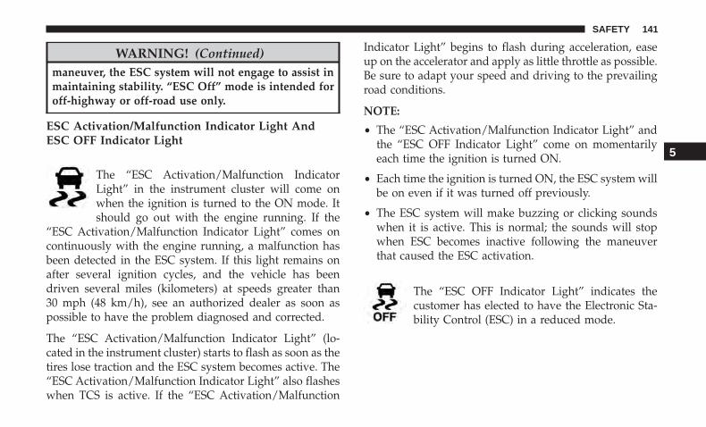
WARNING! (Continued)maneuver, the ESC system will not engage to assist inmaintaining stability. “ESC Off” mode is intended foroff-highway or off-road use only.
ESC Activation/Malfunction Indicator Light AndESC OFF Indicator Light
The “ESC Activation/Malfunction IndicatorLight” in the instrument cluster will come onwhen the ignition is turned to the ON mode. Itshould go out with the engine running. If the
“ESC Activation/Malfunction Indicator Light” comes oncontinuously with the engine running, a malfunction hasbeen detected in the ESC system. If this light remains onafter several ignition cycles, and the vehicle has beendriven several miles (kilometers) at speeds greater than30 mph (48 km/h), see an authorized dealer as soon aspossible to have the problem diagnosed and corrected.
The “ESC Activation/Malfunction Indicator Light” (lo-cated in the instrument cluster) starts to flash as soon as thetires lose traction and the ESC system becomes active. The“ESC Activation/Malfunction Indicator Light” also flasheswhen TCS is active. If the “ESC Activation/Malfunction
Indicator Light” begins to flash during acceleration, easeup on the accelerator and apply as little throttle as possible.Be sure to adapt your speed and driving to the prevailingroad conditions.
NOTE:
• The “ESC Activation/Malfunction Indicator Light” andthe “ESC OFF Indicator Light” come on momentarilyeach time the ignition is turned ON.
• Each time the ignition is turned ON, the ESC system willbe on even if it was turned off previously.
• The ESC system will make buzzing or clicking soundswhen it is active. This is normal; the sounds will stopwhen ESC becomes inactive following the maneuverthat caused the ESC activation.
The “ESC OFF Indicator Light” indicates thecustomer has elected to have the Electronic Sta-bility Control (ESC) in a reduced mode.
5
SAFETY 141

Hill Descent Control (HDC) — If Equipped
HDC is intended for low speed off road driving while in4WD Low Range. HDC maintains vehicle speed whiledescending hills during various driving situations. HDCcontrols vehicle speed by actively controlling the brakes.
HDC has three states:
1. Off (feature is not enabled and will not activate).
2. Enabled (feature is enabled and ready but activationconditions are not met, or driver is actively overridingwith brake or throttle application).
3. Active (feature is enabled and actively controlling ve-hicle speed).
Enabling HDC
HDC is enabled by pushing the HDC switch, but thefollowing conditions must also be met to enable HDC:
• Driveline is in 4WD Low Range.
• Vehicle speed is below 7.5 mph (12 km/h).
• Electric Park Brake (EPB) is released.
• Driver’s door is closed.
Activating HDC
Once HDC is enabled, it will activate automatically ifdriven down a grade of sufficient magnitude (greater thanapproximately 8%). The set speed for HDC is selectable bythe driver and can be adjusted within the thresholds byusing throttle or brake application.
Hill Descent Control (Trailhawk)
142 SAFETY
Driver Override:
The driver may override HDC activation speed withthrottle or brake application at anytime.
Deactivating HDC
HDC will be deactivated but remain available if any of thefollowing conditions occur:
• Driver overrides HDC set speed with a speed exceeding7.5 mph (12 km/h) but remains below 25 mph(40 km/h).
• Vehicle is on a downhill grade of insufficient magnitude(less than approximately 8%), is on level ground, or is onan uphill grade.
• Vehicle is shifted to PARK.
Disabling HDC
HDC will be deactivated and disabled if any of thefollowing conditions occur:
• The driver pushes the HDC switch.
• The driveline is shifted out of 4WD Low Range.
• Driver’s door opens.
• The vehicle is driven greater than 25 mph (40 km/h)(HDC exits immediately.)
Feedback To The Driver:
The instrument cluster has an HDC icon and the HDCswitch has an LED which offer feedback to the driver aboutthe state HDC is in.
• The cluster icon and switch lamp will illuminate andremain solid when HDC is enabled or activated. This isthe normal operating condition for HDC.
• The switch lamp will flash for several seconds thenextinguish when the driver pushes the HDC switchwhen enable conditions have not been met.
The Hill Descent Switch is located within the Selec-Terrainknob in the upper right position.
WARNING!
HDC is only intended to assist the driver in controllingvehicle speed when descending hills. The driver mustremain attentive to the driving conditions and is re-sponsible for maintaining a safe vehicle speed.
5
SAFETY 143

Hill Start Assist (HSA)
The HSA system is designed to mitigate roll back from acomplete stop while on an incline. If the driver releases thebrake while stopped on an incline, HSA will continue tohold the brake pressure for a short period. If the driverdoes not apply the throttle before this time expires, thesystem will release brake pressure and the vehicle will rolldown the hill as normal.
The following conditions must be met in order for HSA toactivate:
• The feature must be enabled.
• The vehicle must be stopped.
• Park brake must be off.
• Driver door must be closed.
• The vehicle must be on a sufficient grade.
• The gear selection must match vehicle uphill direction(i.e., vehicle facing uphill is in forward gear; vehiclebacking uphill is in REVERSE gear).
• HSA will work in REVERSE gear and all forward gears.The system will not activate if the transmission is inPARK or NEUTRAL. For vehicles equipped with amanual transmission, if the clutch is pressed, HSA willremain active.
WARNING!
There may be situations where the Hill Start Assist(HSA) will not activate and slight rolling may occur,such as on minor hills or with a loaded vehicle, orwhile pulling a trailer. HSA is not a substitute foractive driving involvement. It is always the driver’sresponsibility to be attentive to distance to other ve-hicles, people, and objects, and most importantly brakeoperation to ensure safe operation of the vehicle underall road conditions. Your complete attention is alwaysrequired while driving to maintain safe control of yourvehicle. Failure to follow these warnings can result ina collision or serious personal injury.
144 SAFETY

Towing With HSA
HSA will also provide assistance to mitigate roll back whiletowing a trailer.
WARNING!
• If you use a trailer brake controller with your trailer,the trailer brakes may be activated and deactivatedwith the brake switch. If so, there may not be enoughbrake pressure to hold both the vehicle and thetrailer on a hill when the brake pedal is released. Inorder to avoid rolling down an incline while resum-ing acceleration, manually activate the trailer brakeor apply more vehicle brake pressure prior to releas-ing the brake pedal.
• HSA is not a parking brake. Always apply theparking brake fully when exiting your vehicle. Also,be certain to place the transmission in PARK.
• Failure to follow these warnings can result in acollision or serious personal injury.
Disabling And Enabling HSA
This feature can be turned on or turned off. To change thecurrent setting, proceed as follows:
• If disabling HSA using Uconnect Settings, refer to“Uconnect Settings” in “Multimedia” for further infor-mation.
Rain Brake Support (RBS)
Rain Brake Support may improve braking performance inwet conditions. It will periodically apply a small amount ofbrake pressure to remove any water buildup on the frontbrake rotors. It functions when the windshield wipers arein LO or HI speed. When Rain Brake Support is active,there is no notification to the driver and no driver interac-tion is required.
Ready Alert Braking (RAB)
Ready Alert Braking may reduce the time required to reachfull braking during emergency braking situations. It antici-pates when an emergency braking situation may occur bymonitoring how fast the throttle is released by the driver.The EBC will prepare the brake system for a panic stop.
5
SAFETY 145

Trailer Sway Control (TSC)
TSC uses sensors in the vehicle to recognize an excessivelyswaying trailer and will take the appropriate actions toattempt to stop the sway. TSC will become active automati-cally once an excessively swaying trailer is recognized.
NOTE: TSC cannot stop all trailers from swaying. Alwaysuse caution when towing a trailer and follow the trailertongue weight recommendations. Refer to “Trailer Tow-ing” in “Starting And Operating” for further information.
When TSC is functioning, the “ESC Activation/Malfunction Indicator Light” will flash, the engine powermay be reduced and you may feel the brakes being appliedto individual wheels to attempt to stop the trailer fromswaying. TSC is disabled when the ESC system is in the“Partial Off” or “Full Off” modes.
WARNING!
If TSC activates while driving, slow the vehicle down,stop at the nearest safe location, and adjust the trailerload to eliminate trailer sway.
AUXILIARY DRIVING SYSTEMS
Blind Spot Monitoring (BSM) — If Equipped
The Blind Spot Monitoring (BSM) system uses two radar-based sensors, located inside the rear bumper fascia, todetect highway licensable vehicles (automobiles, trucks,motorcycles, etc.) that enter the blind spot zones from therear/front/side of the vehicle.
When the vehicle is started, the BSM warning light willmomentarily illuminate in both outside rear view mirrorsto let the driver know that the system is operational. The
Rear Detection Zones
146 SAFETY
BSM system sensors operate when the vehicle is in anyforward gear or REVERSE and enters stand-by mode whenthe vehicle is in PARK.
The BSM detection zone covers approximately one lanewidth on both sides of the vehicle 12 ft (3.8 m). The zonelength starts at the outside mirror and extends approxi-mately 10 ft (3 m) beyond the rear bumper of the vehicle.The BSM system monitors the detection zones on bothsides of the vehicle when the vehicle speed reaches ap-proximately 6 mph (10 km/h) or higher and will alert thedriver of vehicles in these areas.
NOTE:
• The BSM system does NOT alert the driver aboutrapidly approaching vehicles that are outside the detec-tion zones.
• The BSM system detection zone DOES NOT change ifyour vehicle is towing a trailer. Therefore, visually verifythe adjacent lane is clear for both your vehicle and trailerbefore making a lane change. If the trailer or other object(i.e., bicycle, sports equipment) extends beyond the sideof your vehicle, this may result in the BSM warning lightremaining illuminated the entire time the vehicle is in aforward gear. It may be necessary to deactivate the BSM
system manually to avoid miss-detection. Refer to“Uconnect Settings” in “Multimedia” for further infor-mation.
• The Blind Spot Monitoring (BSM) system may experi-ence drop outs (blinking on and off) of the side mirrorWarning Indicator lamps when a motorcycle or anysmall object remains at the side of the vehicle forextended periods of time (more than a couple of sec-onds).
The area on the rear fascia where the radar sensors arelocated must remain free of snow, ice, and dirt/roadcontamination so that the BSM system can function prop-erly. Do not block the area of the rear fascia where the radarsensors are located with foreign objects (bumper stickers,bicycle racks, etc.)
5
SAFETY 147

The BSM system will provide a visual alert in the appro-priate side view mirror based on a detected object. If theturn signal is then activated, and it corresponds to an alertpresent on that side of the vehicle, an audible chime willalso be sounded. Whenever a turn signal and detectedobject are present on the same side at the same time, boththe visual and audio alerts will be issued. In addition to theaudible alert the radio (if on) will also be muted.
The BSM system monitors the detection zone from threedifferent entry points (side, rear, front) while driving to seeif an alert is necessary. The BSM system will issue an alertduring these types of zone entries.
Radar Sensor Location (Driver Side Shown) Warning Light Location
148 SAFETY

Entering From The Side
Vehicles that move into your adjacent lanes from eitherside of the vehicle.
Entering From The Rear
Vehicles that come up from behind your vehicle on eitherside and enter the rear detection zone with a relative speedof less than 30 mph (48 km/h).
Side MonitoringRear Monitoring
5
SAFETY 149

Overtaking Traffic
If you pass another vehicle slowly with a relative speed lessthan 10 mph (16 km/h) and the vehicle remains in theblind spot for approximately 1.5 seconds, the warning lightwill be illuminated. If the difference in speed between thetwo vehicles is greater than 10 mph (16 km/h), the warninglight will not illuminate.
The BSM system is designed not to issue an alert onstationary objects such as guardrails, posts, walls, foliage,berms, etc. However, occasionally the system may alert onsuch objects. This is normal operation and your vehicledoes not require service.
Overtaking/Approaching
Overtaking/Passing
150 SAFETY

The BSM system will not alert you of objects that aretraveling in the opposite direction of the vehicle in adjacentlanes.
NOTE: The BSM system may experience drop outs (blink-ing on and off) in the side mirror LED icons while amotorcycle, or any small target, remains at the vehicle’sB-pillar for an extended period of time (longer than acouple of seconds).
WARNING!
The Blind Spot Monitoring system is only an aid tohelp detect objects in the blind spot zones. The BSMsystem is not designed to detect pedestrians, bicyclists,or animals. Even if your vehicle is equipped with theBSM system, always check your vehicle’s mirrors,glance over your shoulder, and use your turn signalbefore changing lanes. Failure to do so can result inserious injury or death.
Stationary Objects Opposing Traffic
5
SAFETY 151

Rear Cross Path (RCP)
The Rear Cross Path (RCP) feature is intended to aid thedriver when backing out of parking spaces where theirvision of oncoming vehicles may be blocked. Proceedslowly and cautiously out of the parking space until therear end of the vehicle is exposed. The RCP system willthen have a clear view of the cross traffic and if anoncoming vehicle is detected, alert the driver.
RCP monitors the rear detection zones on both sides of thevehicle, for objects that are moving toward the side of thevehicle with a minimum speed of approximately 3 mph
(5 km/h), to objects moving a maximum of approximately20 mph (32 km/h), such as in parking lot situations.
NOTE: In a parking lot situation, oncoming vehicles can beobscured by vehicles parked on either side. If the sensorsare blocked by other structures or vehicles, the system willnot be able to alert the driver.
When RCP is on and the vehicle is in REVERSE, the driveris alerted using both the visual and audible alarms, includ-ing reducing the radio volume.
WARNING!
Rear Cross Path Detection (RCP) is not a back up aidsystem. It is intended to be used to help a driver detectan oncoming vehicle in a parking lot situation. Driversmust be careful when backing up, even when usingRCP. Always check carefully behind your vehicle, lookbehind you, and be sure to check for pedestrians,animals, other vehicles, obstructions, and blind spotsbefore backing up. Failure to do so can result in seriousinjury or death.RCP Detection Zones
152 SAFETY

Modes Of Operation
Three selectable modes of operation are available in theUconnect System. Refer to “Uconnect Settings” in “Multi-media” for further information.
Blind Spot Alert Lights Only (Default Setting)
When operating in Blind Spot Alert mode, the BSM systemwill provide a visual alert in the appropriate side viewmirror based on a detected object. However, when thesystem is operating in Rear Cross Path (RCP) mode, thesystem will respond with both visual and audible alertswhen a detected object is present. Whenever an audiblealert is requested, the radio is muted.
Blind Spot Alert Lights/Chime
When operating in Blind Spot Alert Lights/Chime mode,the BSM system will provide a visual alert in the appro-priate side view mirror based on a detected object. If theturn signal is then activated, and it corresponds to an alertpresent on that side of the vehicle, an audible chime willalso be sounded. Whenever a turn signal and detectedobject are present on the same side at the same time, boththe visual and audible alerts will be issued. In addition tothe audible alert the radio (if on) will also be muted.
NOTE: Whenever an audible alert is requested by the BSMsystem, the radio is also muted.
When the system is in RCP, the system shall respond withboth visual and audible alerts when a detected object ispresent. Whenever an audible alert is requested, the radiovolume is reduced. Turn/hazard signal status is ignored;the RCP state always requests the chime.
Blind Spot Alert Off
When the BSM system is turned off there will be no visualor audible alerts from either the BSM or RCP systems.
NOTE: The BSM system will store the current operatingmode when the vehicle is shut off. Each time the vehicle isstarted the previously stored mode will be recalled andused.
Blocked Sensor
If the system detects degraded performance due to con-tamination or foreign objects, a message will warn you of ablocked sensor and the warning indicators in side viewmirrors will be illuminated. The warning indicators willremain illuminated until blockage clearing conditions aremet. First clear the fascia area around the sensors of the
5
SAFETY 153

blockage. After removing the blockage, reset the system bycycling the ignition from ON to OFF and then back ON.
General Information
The following regulatory statement applies to all RadioFrequency (RF) devices equipped in this vehicle:
This device complies with Part 15 of the FCC Rules andwith Industry Canada license-exempt RSS standard(s).Operation is subject to the following two conditions:
1. This device may not cause harmful interference.
2. This device must accept any interference received, in-cluding interference that may cause undesired opera-tion.
NOTE: Changes or modifications not expressly approvedby the party responsible for compliance could void theuser’s authority to operate the equipment.
Forward Collision Warning (FCW) With Mitigation— If Equipped
Forward Collision Warning (FCW) With MitigationOperation
The Forward Collision Warning (FCW) system with miti-gation provides the driver with audible warnings, visual
warnings (within the instrument cluster display), and mayapply a brake jerk to warn the driver when it detects apotential frontal collision. The warnings and limited brak-ing are intended to provide the driver with enough time toreact, avoid or mitigate the potential collision.
NOTE: FCW monitors the information from the forwardlooking sensors as well as the Electronic Brake Controller(EBC), to calculate the probability of a forward collision.When the system determines that a forward collision isprobable, the driver will be provided with audible andvisual warnings and may provide a brake jerk warning.
If the driver does not take action based upon these pro-gressive warnings, then the system will provide a limitedlevel of active braking to help slow the vehicle and mitigatethe potential forward collision. If the driver reacts to thewarnings by braking and the system determines that thedriver intends to avoid the collision by braking but has notapplied sufficient brake force, the system will compensateand provide additional brake force as required.
If a Forward Collision Warning with Mitigation eventbegins at a speed below 26 mph (42 km/h), the system mayprovide the maximum braking possible to mitigate thepotential forward collision. If the Forward Collision Warn-ing with Mitigation event stops the vehicle completely, the
154 SAFETY

system will hold the vehicle at standstill for two secondsand then release the brakes.
When the system determines a collision with the vehicle infront of you is no longer probable, the warning messagewill be deactivated.
NOTE:
• The minimum speed for FCW activation is 1 mph(2 km/h).
• The FCW alerts may be triggered on objects other thanvehicles such as guard rails or sign posts based on the
course prediction. This is expected and is a part ofnormal FCW activation and functionality.
• It is unsafe to test the FCW system. To prevent suchmisuse of the system, after four Active Braking eventswithin a key cycle, the Active Braking portion of FCWwill be deactivated until the next key cycle.
• The FCW system is intended for on-road use only. If thevehicle is taken off-road, the FCW system should bedeactivated to prevent unnecessary warnings to thesurroundings.
WARNING!
Forward Collision Warning (FCW) is not intended toavoid a collision on its own, nor can FCW detect everytype of potential collision. The driver has the respon-sibility to avoid a collision by controlling the vehiclevia braking and steering. Failure to follow this warn-ing could lead to serious injury or death.
FCW Settings
The forward collision menu setting is located in theUconnect settings.
FCW Message
5
SAFETY 155

NOTE: The default status of FCW is “Full On,” this allowsthe system to provide warning and autonomous braking inthe event of a potential frontal collision.
Changing the FCW status to “Warning Only” prevents thesystem from providing autonomous braking, or additionalbrake support if the driver is not braking adequately in theevent of a potential frontal collision.
Changing the FCW status to off deactivates the system, sono warning or autonomous braking will be available incase of a possible collision
NOTE: The FCW system state is kept in memory from oneignition cycle to the next. If the system is turned off, it willremain off when the vehicle is restarted.
Changing FCW Sensitivity And Operating Status
The FCW Sensitivity And Operation Settings are program-mable through the Uconnect System. Refer to “UconnectSettings” in “Multimedia” for further information.
The default status of FCW is the “Medium” setting and theFCW is in the “Full On” setting. This allows the system towarn the driver of a possible collision with the vehicle infront using audible/visual warnings and it applies autono-mous braking.
Changing the FCW status to “Far” setting allows thesystem to warn the driver of a possible collision with thevehicle in front using audible/visual warning when thelatter is at a farther distance than �Medium� setting. Thisprovides the most reaction time to avoid a possible colli-sion.
Changing the FCW status to the “Near” setting, allows thesystem to warn the driver of a possible collision with thevehicle in front when the distance between the vehicle inthe front is much closer. This setting provides less reactiontime than the “Far” and “Medium” settings, which allowsfor a more dynamic driving experience.
NOTE:
• The system will retain the last setting selected by thedriver after ignition shut down.
• FCW may not react to irrelevant objects such as over-head objects, ground reflections, objects not in the pathof the vehicle, stationary objects that are far away,oncoming traffic, or leading vehicles with the same orhigher rate of speed.
• If FCW is disabled, unavailable screens will be dis-played.
156 SAFETY

FCW Limited Warning
If the instrument cluster display reads “FCW LimitedFunctionality” or “FCW Limited Functionality Clean FrontWindshield” momentarily, there may be a condition thatlimits FCW functionality. Although the vehicle is stilldrivable under normal conditions, the active braking maynot be fully available. Once the condition that limited thesystem performance is no longer present, the system willreturn to its full performance state. If the problem persists,see your authorized dealer.
Service FCW Warning
If the system turns off, and the instrument cluster displayreads “FCW Unavailable Service Required”, there is aninternal system fault. Although the vehicle is still drivableunder normal conditions, have the system checked by anauthorized dealer.
General Information
The following regulatory statement applies to all RadioFrequency (RF) devices equipped in this vehicle:
This device complies with Part 15 of the FCC Rules andwith Industry Canada license-exempt RSS standard(s).Operation is subject to the following two conditions:
1. This device may not cause harmful interference.
2. This device must accept any interference received, in-cluding interference that may cause undesired opera-tion.
NOTE: Changes or modifications not expressly approvedby the party responsible for compliance could void theuser’s authority to operate the equipment.
Tire Pressure Monitor System (TPMS)
The Tire Pressure Monitor System (TPMS) will warn thedriver of a low tire pressure based on the vehicle recom-mended cold placard pressure.
The tire pressure will vary with temperature by approxi-mately 1 psi (7 kPa) for every 12°F (6.5°C). This means thatwhen the outside temperature decreases, the tire pressurewill decrease. Tire pressure should always be set based oncold inflation tire pressure. This is defined as the tirepressure after the vehicle has not been driven for at leastthree hours, or driven less than 1 mile (1.6 km) after a threehour period. The cold tire inflation pressure must notexceed the maximum inflation pressure molded into thetire sidewall. Refer to “Tires” in “Servicing And Mainte-nance” for information on how to properly inflate the
5
SAFETY 157

vehicle’s tires. The tire pressure will also increase as thevehicle is driven. This is normal and there should be noadjustment for this increased pressure.
The TPMS will warn the driver of a low tire pressure if thetire pressure falls below the low-pressure warning limit forany reason, including low temperature effects and naturalpressure loss through the tire. The TPMS will continue towarn the driver of low tire pressure as long as thecondition exists, and will not turn off until the tire pressureis at or above the recommended cold placard pressure.
NOTE: Once the low tire pressure warning (Tire PressureMonitoring System Warning Light) illuminates, you mustincrease the tire pressure to the recommended cold placardpressure in order for the Tire Pressure Monitoring SystemWarning Light to turn off.
NOTE: When filling warm tires, the tire pressure may needto be increased up to an additional 4 psi (28 kPa) above therecommended cold placard pressure in order to turn theTire Pressure Monitoring System Warning Light off.
The system will automatically update and the Tire PressureMonitoring System Warning Light will turn off once thesystem receives the updated tire pressures. The vehicle
may need to be driven for up to 20 minutes above 15 mph(24 km/h) in order for the TPMS to receive this informa-tion.
For example, your vehicle may have a recommended cold(parked for more than three hours) placard pressure of33 psi (227 kPa). If the ambient temperature is 68°F (20°C)and the measured tire pressure is 28 psi (193 kPa), atemperature drop to 20°F (-7°C) will decrease the tirepressure to approximately 24 psi (165 kPa). This tirepressure is low enough to turn on the Tire PressureMonitoring System Warning Light. Driving the vehiclemay cause the tire pressure to rise to approximately 28 psi(193 kPa), but the Tire Pressure Monitoring System Warn-ing Light will still be on. In this situation, the Tire PressureMonitoring System Warning Light will turn off only afterthe tires are inflated to the vehicle’s recommended coldplacard pressure value.
NOTE: When filling warm tires, the tire pressure may needto be increased up to an additional 4 psi (28 kPa) above therecommended cold placard pressure in order to turn theTire Pressure Monitoring System Warning Light off.
158 SAFETY

CAUTION!
• The TPMS has been optimized for the originalequipment tires and wheels. TPMS pressures andwarning have been established for the tire sizeequipped on your vehicle. Undesirable system op-eration or sensor damage may result when usingreplacement equipment that is not of the same size,type, and/or style. The TPM sensor is not designedfor use on aftermarket wheels and may contribute toa poor overall system performance or sensor damage.Customers are encouraged to use OEM wheels toassure proper TPM feature operation.
• Using aftermarket tire sealants may cause the TirePressure Monitoring System (TPMS) sensor to be-come inoperable. After using an aftermarket tiresealant it is recommended that you take your vehicleto your authorized dealer to have your sensor func-tion checked.
• After inspecting or adjusting the tire pressure alwaysreinstall the valve stem cap. This will prevent mois-ture and dirt from entering the valve stem, whichcould damage the TPMS sensor.
NOTE:
• The TPMS is not intended to replace normal tire care andmaintenance, or to provide warning of a tire failure orcondition.
• The TPMS should not be used as a tire pressure gaugewhile adjusting your tire pressure.
• Driving on a significantly underinflated tire causes thetire to overheat and can lead to tire failure. Underinfla-tion also reduces fuel efficiency and tire tread life, andmay affect the vehicle’s handling and stopping ability.
• The TPMS is not a substitute for proper tire mainte-nance, and it is the driver’s responsibility to maintaincorrect tire pressure using an accurate tire pressuregauge, even if underinflation has not reached the level totrigger illumination of the Tire Pressure MonitoringSystem Warning Light.
• Seasonal temperature changes will affect tire pressure,and the TPMS will monitor the actual tire pressure in thetire.
5
SAFETY 159

Base System
The Tire Pressure Monitor System (TPMS) uses wirelesstechnology with wheel rim mounted electronic sensors tomonitor tire pressure levels. Sensors, mounted to eachwheel as part of the valve stem, transmit tire pressurereadings to the receiver module.
NOTE: It is particularly important for you to check the tirepressure in all of the tires on your vehicle monthly and tomaintain the proper pressure.
The TPMS consists of the following components:
• Receiver Module
• Four Tire Pressure Monitoring Sensors
• Tire Pressure Monitoring System Warning Light
Tire Pressure Monitoring Low Pressure Warnings
The Tire Pressure Monitoring System Warning Lightwill illuminate in the instrument cluster, a “LOW
TIRE PRESSURE” message will display in the instrumentcluster and a chime will sound when tire pressure is low inone or more of the four active road tires. Should this occur,you should stop as soon as possible, check the inflationpressure of each tire on your vehicle, and inflate each tire to
the vehicle’s recommended cold placard pressure value.Once the system receives the updated tire pressures, thesystem will automatically update and the Tire PressureMonitoring System Warning Light will turn off.
NOTE: When filling warm tires, the tire pressure may needto be increased up to an additional 4 psi (28 kPa) above therecommended cold placard pressure in order to turn theTire Pressure Monitoring System Warning Light off. Thevehicle may need to be driven for up to 20 minutes above15 mph (24 km/h) in order for the TPMS to receive thisinformation.
Service TPMS Warning
When a system fault is detected, the Tire Pressure Moni-toring System Warning Light will flash on and off for 75seconds and then remain on solid. The system fault willalso sound a chime. If the ignition is cycled, this sequencewill repeat, providing the system fault still exists. The TirePressure Monitoring System Warning Light will turn offwhen the fault condition no longer exists. A system faultcan occur due to any of the following:
• Jamming due to electronic devices or driving next tofacilities emitting the same radio frequencies as theTPMS sensors.
160 SAFETY
• Installing some form of aftermarket window tinting thataffects radio wave signals.
• Lots of snow or ice around the wheels or wheel hous-ings.
• Using tire chains on the vehicle.
• Using wheels/tires not equipped with TPMS sensors.
Vehicles With Compact Spare or non-Matching Full SizeSpare
1. The compact spare tire or non-matching full size sparetire does not have a tire pressure monitoring sensor.Therefore, the TPMS will not monitor the pressure in thespare tire.
2. If you install the compact or non-matching full sizespare tire in place of a road tire that has a pressure belowthe low-pressure warning limit, a chime will sound andthe “Tire Pressure Monitoring System Warning Light”and “LOW TIRE PRESSURE” message will turn onupon the next ignition cycle.
3. After driving the vehicle for up to 20 minutes above15 mph (24 km/h), the Tire Pressure Monitoring SystemWarning Light will flash on and off for 75 seconds andthen remain on solid.
4. For each subsequent ignition cycle, a chime will soundand the Tire Pressure Monitoring System Warning Lightwill flash on and off for 75 seconds and then remain onsolid.
5. Once you repair or replace the original road tire andreinstall it on the vehicle in place of the compact spare ornon-matching full size spare, the TPMS will updateautomatically and the Tire Pressure Monitoring SystemWarning Light will turn off, as long as no tire pressure isbelow the low-pressure warning limit in any of the fouractive road tires. The vehicle may need to be driven forup to 20 minutes above 15 mph (24 km/h) in order forthe TPMS to receive this information.
Premium System — If Equipped
The Tire Pressure Monitor System (TPMS) uses wirelesstechnology with wheel rim mounted electronic sensors tomonitor tire pressure levels. Sensors, mounted to eachwheel as part of the valve stem, transmit tire pressurereadings to the receiver module.
NOTE: It is particularly important for you to check the tirepressure in all of the tires on your vehicle monthly and tomaintain the proper pressure.
5
SAFETY 161

The TPMS consists of the following components:
• Receiver Module
• Four Tire Pressure Monitoring Sensors
• Various Tire Pressure Monitoring System messages,which will display in the instrument cluster display.
• Tire Pressure Monitoring System Warning Light
Tire Pressure Monitoring Low Pressure Warnings
The Tire Pressure Monitoring System Warning Lightwill illuminate in the instrument cluster and a
chime will sound when tire pressure is low in one or moreof the four active road tires. In addition, the instrumentcluster will display a �Tire Low� message, an “Inflate toXX” message, and a graphic showing the pressure valuesof each tire with the low tire pressure values highlighted orin a different color.
Should this occur, you should stop as soon as possible andinflate the tires with low pressure (those highlighted or ina different color in the instrument cluster display graphic)to the vehicle’s recommended cold placard pressure value,as shown in the “Inflate to XX” message. Once the systemreceives the updated tire pressures, the system will auto-matically update, the pressure values in the graphic dis-play in the instrument cluster will stop being highlightedor return to their original color, and the Tire PressureMonitoring System Warning Light will turn off.
Tire Pressure Monitoring Low Pressure Warning
162 SAFETY

NOTE: When filling warm tires, the tire pressure may needto be increased up to an additional 4 psi (28 kPa) above therecommended cold placard pressure in order to turn theTire Pressure Monitoring System Warning Light off.The vehicle may need to be driven for up to 20 minutesabove 15 mph (24 km/h) in order for the TPMS to receivethis information.
SERVICE TPMS Warning
When a system fault is detected, the Tire Pressure Moni-toring System Warning Light will flash on and off for 75seconds and then remain on solid. The system fault willalso sound a chime. In addition, the instrument cluster willdisplay a �SERVICE TPM SYSTEM� message for a mini-mum of five seconds and then display dashes (- -) in placeof the pressure value to indicate which sensor is not beingreceived.
If the ignition key is cycled, this sequence will repeat,providing the system fault still exists. If the system fault nolonger exists, the Tire Pressure Monitoring System WarningLight will no longer flash, and the “SERVICE TPM SYS-TEM” message will no longer display, and a pressure valuewill display in place of the dashes. A system fault can occurdue to any of the following:
• Jamming due to electronic devices or driving next tofacilities emitting the same radio frequencies as theTPMS sensors.
• Installing some form of aftermarket window tinting thataffects radio wave signals.
• Lots of snow or ice around the wheels or wheel housings.
• Using tire chains on the vehicle.
• Using wheels/tires not equipped with TPMS sensors.
Vehicles With Compact Spare or Non-Matching Full SizeSpare
1. The compact spare tire or non-matching full size doesnot have a tire pressure monitoring sensor. Therefore,the TPMS will not monitor the pressure in the compactspare tire.
2. If you install the compact or non-matching full sizespare tire in place of a road tire that has a pressure belowthe low-pressure warning limit, upon the next ignitionkey cycle, the Tire Pressure Monitoring System WarningLight will remain on and a chime will sound. Inaddition, the graphic in the instrument cluster will stilldisplay a different color or highlighted pressure valueand the “Inflate to XX” message.
5
SAFETY 163

3. After driving the vehicle for up to 20 minutes above15 mph (24 km/h), the Tire Pressure Monitoring SystemWarning Light will flash on and off for 75 seconds andthen remain on solid. In addition, the instrument clusterwill display a “SERVICE TPM SYSTEM” message forfive seconds and then display dashes (- -) in place of thepressure value.
4. For each subsequent ignition key cycle, a chime willsound, the Tire Pressure Monitoring System WarningLight will flash on and off for 75 seconds and then remainon solid, and the instrument cluster will display a “SER-VICE TPM SYSTEM” message for five seconds and thendisplay dashes (- -) in place of the pressure value.
5. Once you repair or replace the original road tire andreinstall it on the vehicle in place of the compact spare ornon-matching full size, the TPMS will update automati-cally. In addition, the Tire Pressure Monitoring SystemWarning Light will turn off and the graphic in theinstrument cluster will display a new pressure valueinstead of dashes (- -), as long as no tire pressure isbelow the low-pressure warning limit in any of the fouractive road tires. The vehicle may need to be driven forup to 20 minutes above 15 mph (24 km/h) in order forthe TPMS to receive this information.
TPMS Deactivation — If Equipped
The TPMS can be deactivated if replacing all four wheeland tire assemblies (road tires) with wheel and tire assem-blies that do not have TPMS Sensors, such as wheninstalling winter wheel and tire assemblies on your vehicle.
To deactivate the TPMS, first replace all four wheel and tireassemblies (road tires) with tires not equipped with TirePressure Monitoring (TPM) Sensors. Then, drive the ve-hicle for 20 minutes above 15 mph (24 km/h). The TPMSwill chime, the Tire Pressure Monitoring System WarningLight will flash on and off for 75 seconds and then remainon. The instrument cluster will display the “SERVICE TPMSYSTEM” message and then display dashes (--) in place ofthe pressure values.
Beginning with the next ignition cycle, the TPMS will nolonger chime or display the “SERVICE TPM SYSTEM”message in the instrument cluster but dashes (--) willremain in place of the pressure values.
To reactivate the TPMS, replace all four wheel and tireassemblies (road tires) with tires equipped with TPMsensors. Then, drive the vehicle for up to 20 minutes above15 mph (24 km/h). The TPMS will chime, the Tire PressureMonitoring System Warning Light will flash on and off for75 seconds and then turn off. The instrument cluster will
164 SAFETY

display the “SERVICE TPM SYSTEM” message and thendisplay pressure values in place of the dashes. On the nextignition cycle the �SERVICE TPM SYSTEM� message willno longer be displayed as long as no system fault exists.
General Information
The following regulatory statement applies to all radiofrequency (RF) devices equipped in this vehicle:
This device complies with Part 15 of the FCC Rules andwith Industry Canada license-exempt RSS standard(s).Operation is subject to the following two conditions:
(1) This device may not cause harmful interference, and
(2) This device must accept any interference received,including interference that may cause undesired operation.
NOTE: Changes or modifications not expressly approvedby the party responsible for compliance could void theuser’s authority to operate the equipment.
OCCUPANT RESTRAINT SYSTEMS
Some of the most important safety features in your vehicleare the restraint systems:
Occupant Restraint Systems Features
• Seat Belt Systems
• Supplemental Restraint Systems (SRS) Air Bags
• Child Restraints
Some of the safety features described in this section may bestandard equipment on some models, or may be optionalequipment on others. If you are not sure, ask your autho-rized dealer.
Important Safety Precautions
Please pay close attention to the information in this section.It tells you how to use your restraint system properly, tokeep you and your passengers as safe as possible.
Here are some simple steps you can take to minimize therisk of harm from a deploying air bag:
1. Children 12 years old and under should always ridebuckled up in the rear seat of a vehicle with a rear seat.
2. If a child from 2 to 12 years old (not in a rear-facing childrestraint) must ride in the front passenger seat, move theseat as far back as possible and use the proper childrestraint (refer to “Child Restraints” in this section forfurther information).
5
SAFETY 165
3. Children that are not big enough to wear the vehicle seatbelt properly (refer to “Child Restraints” in this sectionfor further information) should be secured in the rearseat of a vehicle with a rear seat in child restraints orbelt-positioning booster seats. Older children who donot use child restraints or belt-positioning booster seatsshould ride properly buckled up in the rear seat of avehicle with a rear seat.
4. Never allow children to slide the shoulder belt behindthem or under their arm.
5. You should read the instructions provided with yourchild restraint to make sure that you are using itproperly.
6. All occupants should always wear their lap and shoul-der belts properly.
7. The driver and front passenger seats should be movedback as far as practical to allow the front air bags roomto inflate.
8. Do not lean against the door or window. If your vehiclehas side air bags, and deployment occurs, the side airbags will inflate forcefully into the space between occu-pants and the door and occupants could be injured.
9. If the air bag system in this vehicle needs to be modifiedto accommodate a disabled person, refer to the “Cus-tomer Assistance” section for customer service contactinformation.
WARNING!
• Never place a rear-facing child restraint in front of anair bag. A deploying passenger front air bag cancause death or serious injury to a child 12 years oryounger, including a child in a rear-facing childrestraint.
• Only use a rear-facing child restraint in the rear seatof a vehicle with a rear seat.
Seat Belt Systems
Buckle up even though you are an excellent driver, even onshort trips. Someone on the road may be a poor driver andcould cause a collision that includes you. This can happenfar away from home or on your own street.
Research has shown that seat belts save lives, and they canreduce the seriousness of injuries in a collision. Some of theworst injuries happen when people are thrown from thevehicle. Seat belts reduce the possibility of ejection and the
166 SAFETY

risk of injury caused by striking the inside of the vehicle.Everyone in a motor vehicle should be belted at all times.
Enhanced Seat Belt Use Reminder System (BeltAlert)
Driver and Passenger BeltAlert (if equipped)
BeltAlert is a feature intended to remind the driverand outboard front seat passenger (if equipped withoutboard front passenger seat BeltAlert) to buckle theirseat belts. The Belt Alert feature is active whenever theignition switch is in the START or ON/RUN position.
Initial Indication
If the driver is unbuckled when the ignition switch is firstin the START or ON/RUN position, a chime will signal fora few seconds. If the driver or outboard front seat passen-ger (if equipped with outboard front passenger seatBeltAlert) is unbuckled when the ignition switch is first inthe START or ON/RUN position the Seat Belt ReminderLight will turn on and remain on until both outboard frontseat belts are buckled. The outboard front passenger seatBeltAlert is not active when an outboard front passengerseat is unoccupied.
BeltAlert Warning Sequence
The BeltAlert warning sequence is activated when thevehicle is moving above a specified vehicle speed rangeand the driver or outboard front seat passenger is unbuck-led (if equipped with outboard front passenger seatBeltAlert) (the outboard front passenger seat BeltAlert isnot active when the outboard front passenger seat isunoccupied). The BeltAlert warning sequence starts byblinking the Seat Belt Reminder Light and sounding anintermittent chime. Once the BeltAlert warning sequencehas completed, the Seat Belt Reminder Light will remain onuntil the seat belts are buckled. The BeltAlert warningsequence may repeat based on vehicle speed until thedriver and occupied outboard front seat passenger seatbelts are buckled. The driver should instruct all occupantsto buckle their seat belts.
Change of Status
If the driver or outboard front seat passenger (if equippedwith outboard front passenger seat BeltAlert) unbucklestheir seat belt while the vehicle is traveling, the BeltAlertwarning sequence will begin until the seat belts are buck-led again.
5
SAFETY 167

The outboard front passenger seat BeltAlert is not activewhen the outboard front passenger seat is unoccupied.BeltAlert may be triggered when an animal or other itemsare placed on the outboard front passenger seat or whenthe seat is folded flat (if equipped). It is recommended thatpets be restrained in the rear seat (if equipped) in petharnesses or pet carriers that are secured by seat belts, andcargo is properly stowed.
BeltAlert can be activated or deactivated by your autho-rized dealer. FCA US LLC does not recommend deactivat-ing BeltAlert.
NOTE: If BeltAlert has been deactivated and the driver oroutboard front seat passenger (if equipped with outboardfront passenger seat BeltAlert) is unbuckled the Seat BeltReminder Light will turn on and remain on until the driverand outboard front seat passenger seat belts are buckled.
Lap/Shoulder Belts
All seating positions in your vehicle are equipped withlap/shoulder belts.
The seat belt webbing retractor will lock only during verysudden stops or collisions. This feature allows the shoulderpart of the seat belt to move freely with you under normalconditions. However, in a collision the seat belt will lock
and reduce your risk of striking the inside of the vehicle orbeing thrown out of the vehicle.
WARNING!
• Relying on the air bags alone could lead to moresevere injuries in a collision. The air bags work withyour seat belt to restrain you properly. In somecollisions, the air bags won’t deploy at all. Alwayswear your seat belt even though you have air bags.
• In a collision, you and your passengers can suffermuch greater injuries if you are not properly buckledup. You can strike the interior of your vehicle orother passengers, or you can be thrown out of thevehicle. Always be sure you and others in yourvehicle are buckled up properly.
• It is dangerous to ride in a cargo area, inside oroutside of a vehicle. In a collision, people riding inthese areas are more likely to be seriously injured orkilled.
• Do not allow people to ride in any area of yourvehicle that is not equipped with seats and seat belts.
• Be sure everyone in your vehicle is in a seat andusing a seat belt properly. Occupants, including the
(Continued)
168 SAFETY
WARNING! (Continued)driver, should always wear their seat belts whetheror not an air bag is also provided at their seatingposition to minimize the risk of severe injury ordeath in the event of a crash.
• Wearing your seat belt incorrectly could make yourinjuries in a collision much worse. You might sufferinternal injuries, or you could even slide out of theseat belt. Follow these instructions to wear your seatbelt safely and to keep your passengers safe, too.
• Two people should never be belted into a single seatbelt. People belted together can crash into one an-other in a collision, hurting one another badly. Neveruse a lap/shoulder belt or a lap belt for more than oneperson, no matter what their size.
WARNING!
• A lap belt worn too high can increase the risk ofinjury in a collision. The seat belt forces won’t be atthe strong hip and pelvic bones, but across yourabdomen. Always wear the lap part of your seat beltas low as possible and keep it snug.
(Continued)
WARNING! (Continued)• A twisted seat belt may not protect you properly. In
a collision, it could even cut into you. Be sure the seatbelt is flat against your body, without twists. If youcan’t straighten a seat belt in your vehicle, take it toyour authorized dealer immediately and have itfixed.
• A seat belt that is buckled into the wrong buckle willnot protect you properly. The lap portion could ridetoo high on your body, possibly causing internalinjuries. Always buckle your seat belt into thebuckle nearest you.
• A seat belt that is too loose will not protect youproperly. In a sudden stop, you could move too farforward, increasing the possibility of injury. Wearyour seat belt snugly.
• A seat belt that is worn under your arm is dangerous.Your body could strike the inside surfaces of thevehicle in a collision, increasing head and neckinjury. A seat belt worn under the arm can causeinternal injuries. Ribs aren’t as strong as shoulderbones. Wear the seat belt over your shoulder so thatyour strongest bones will take the force in a collision.
(Continued)
5
SAFETY 169

WARNING! (Continued)• A shoulder belt placed behind you will not protect
you from injury during a collision. You are morelikely to hit your head in a collision if you do notwear your shoulder belt. The lap and shoulder beltare meant to be used together.
• A frayed or torn seat belt could rip apart in a collisionand leave you with no protection. Inspect the seatbelt system periodically, checking for cuts, frays, orloose parts. Damaged parts must be replaced imme-diately. Do not disassemble or modify the seat beltsystem. Seat belt assemblies must be replaced after acollision.
Lap/Shoulder Belt Operating Instructions
1. Enter the vehicle and close the door. Sit back and adjustthe seat.
2. The seat belt latch plate is above the back of the frontseat, and next to your arm in the rear seat (for vehiclesequipped with a rear seat). Grasp the latch plate andpull out the seat belt. Slide the latch plate up thewebbing as far as necessary to allow the seat belt to goaround your lap.
3. When the seat belt is long enough to fit, insert the latchplate into the buckle until you hear a “click.”
Pulling Out The Latch Plate
170 SAFETY

4. Position the lap belt so that it is snug and lies low acrossyour hips, below your abdomen. To remove slack in thelap belt portion, pull up on the shoulder belt. To loosenthe lap belt if it is too tight, tilt the latch plate and pullon the lap belt. A snug seat belt reduces the risk ofsliding under the seat belt in a collision.
5. Position the shoulder belt across the shoulder and chestwith minimal, if any slack so that it is comfortable andnot resting on your neck. The retractor will withdrawany slack in the shoulder belt.
6. To release the seat belt, push the red button on thebuckle. The seat belt will automatically retract to itsstowed position. If necessary, slide the latch plate downthe webbing to allow the seat belt to retract fully.
Inserting Latch Plate Into Buckle Positioning The Lap Belt
5
SAFETY 171

Lap/Shoulder Belt Untwisting Procedure
Use the following procedure to untwist a twisted lap/shoulder belt.
1. Position the latch plate as close as possible to the anchorpoint.
2. At about 6 to 12 inches (15 to 30 cm) above the latchplate, grasp and twist the seat belt webbing 180 degreesto create a fold that begins immediately above the latchplate.
3. Slide the latch plate upward over the folded webbing.The folded webbing must enter the slot at the top of thelatch plate.
4. Continue to slide the latch plate up until it clears thefolded webbing and the seat belt is no longer twisted.
Adjustable Upper Shoulder Belt Anchorage
In the driver and front passenger seats, the top of theshoulder belt can be adjusted upward or downward toposition the seat belt away from your neck. Push orsqueeze the anchorage button to release the anchorage, andmove it up or down to the position that serves you best.
As a guide, if you are shorter than average, you will preferthe shoulder belt anchorage in a lower position, and if youare taller than average, you will prefer the shoulder beltanchorage in a higher position. After you release theanchorage button, try to move it up or down to make surethat it is locked in position.
Adjustable Anchorage
172 SAFETY

NOTE: The adjustable upper shoulder belt anchorage isequipped with an Easy Up feature. This feature allows theshoulder belt anchorage to be adjusted in the upwardposition without pushing or squeezing the release button.To verify the shoulder belt anchorage is latched, pulldownward on the shoulder belt anchorage until it is lockedinto position.
WARNING!
• Wearing your seat belt incorrectly could make yourinjuries in a collision much worse. You might sufferinternal injuries, or you could even slide out of theseat belt. Follow these instructions to wear your seatbelt safely and to keep your passengers safe, too.
• Position the shoulder belt across the shoulder andchest with minimal, if any slack so that it is comfort-able and not resting on your neck. The retractor willwithdraw any slack in the shoulder belt.
• Misadjustment of the seat belt could reduce theeffectiveness of the safety belt in a crash.
Second Row Center Seat Belt Operating Instructions
The second row center seat belt may feature a seat belt witha mini-latch plate and buckle. The mini-latch plate andbuckle, if equipped, should remain connected at all times.If the mini-latch plate and buckle become disconnected,they must be properly reconnected prior to the rear centerseat belt being used by an occupant.
1. Grasp the mini-latch plate and pull the seat belt over theseat.
Pulling Out The Latch Plate
5
SAFETY 173

2. When the seat belt is long enough to fit, insert themini-latch plate into the mini-buckle until you hear a“click.”
3. Sit back in seat. Slide the regular latch plate up thewebbing as far as necessary to allow the seat belt to goaround your lap.
4. When the seat belt is long enough to fit, insert the latchplate into the buckle until you hear a “click.”
Inserting Mini-Latch Plate Into Mini-BuckleInserting Latch Plate Into Buckle
174 SAFETY

5. Position the lap belt so that it is snug and lies low acrossyour hips, below your abdomen. To remove slack in thelap belt portion, pull up on the shoulder belt. To loosenthe lap belt if it is too tight, pull on the lap belt. A snugseat belt reduces the risk of sliding under the seat belt ina collision.
6. Position the shoulder belt on your chest so that it iscomfortable and not resting on your neck. The retractorwill withdraw any slack in the seat belt.
7. To release the seat belt, push the red button on thebuckle.
8. To disengage the mini-latch plate from the mini-buckle,insert the regular latch plate into the center red slot onthe mini-buckle.
WARNING!
• If the mini-latch plate and mini-buckle are not prop-erly connected when the seat belt is used by an
(Continued)
Inserting Latch Plate Into Buckle
Detaching Mini-Buckle With Seat Belt Tongue
5
SAFETY 175
WARNING! (Continued)occupant, the seat belt will not be able to provideproper restraint and will increase the risk of injury ina collision.
• When reattaching the mini-latch plate and mini-buckle, ensure the seat belt webbing is not twisted.If the webbing is twisted, follow the precedingprocedure to detach the mini-latch plate and mini-buckle, untwist the webbing, and reattach the mini-latch plate and mini-buckle.
Seat Belt Extender
If a seat belt is not long enough to fit properly, even whenthe webbing is fully extended and the adjustable uppershoulder belt anchorage (if equipped) is in its lowestposition, your authorized dealer can provide you with aSeat Belt Extender. The Seat Belt Extender should be usedonly if the existing seat belt is not long enough. When theSeat Belt Extender is not required for a different occupant,it must be removed.
WARNING!
• ONLY use a Seat Belt Extender if it is physicallyrequired in order to properly fit the original seat beltsystem. DO NOT USE the Seat Belt Extender if,when worn, the distance between the front edge ofthe Seat Belt Extender buckle and the center of theoccupant’s body is LESS than 6 inches.
• Using a Seat Belt Extender when not needed canincrease the risk of serious injury or death in acollision. Only use the Seat Belt Extender when thelap belt is not long enough and only use in therecommended seating positions. Remove and storethe Seat Belt Extender when not needed.
176 SAFETY

Seat Belts And Pregnant Women
Seat belts must be worn by all occupants including preg-nant women: the risk of injury in the event of an accidentis reduced for the mother and the unborn child if they arewearing a seat belt.
Position the lap belt snug and low below the abdomen andacross the strong bones of the hips. Place the shoulder beltacross the chest and away from the neck. Never place theshoulder belt behind the back or under the arm.
Seat Belt Pretensioner
The front seat belt system is equipped with pretensioningdevices that are designed to remove slack from the seat beltin the event of a collision. These devices may improve theperformance of the seat belt by removing slack from theseat belt early in a collision. Pretensioners work for all sizeoccupants, including those in child restraints.
NOTE: These devices are not a substitute for proper seatbelt placement by the occupant. The seat belt still must beworn snugly and positioned properly.
The pretensioners are triggered by the Occupant RestraintController (ORC). Like the air bags, the pretensioners aresingle use items. A deployed pretensioner or a deployed airbag must be replaced immediately.
Energy Management Feature
The front seat belt system is equipped with an EnergyManagement feature that may help further reduce the riskof injury in the event of a collision. The seat belt system hasa retractor assembly that is designed to release webbing ina controlled manner.
Pregnant Women And Seat Belts
5
SAFETY 177

Switchable Automatic Locking Retractors (ALR)
The seat belts in the passenger seating positions areequipped with a Switchable Automatic Locking Retractor(ALR) which is used to secure a child restraint system. Foradditional information, refer to “Installing Child RestraintsUsing The Vehicle Seat Belt” under the “Child Restraints”section of this manual. The figure below illustrates thelocking feature for each seating position.
If the passenger seating position is equipped with an ALRand is being used for normal usage, only pull the seat beltwebbing out far enough to comfortably wrap around theoccupant’s mid-section so as to not activate the ALR. If the
ALR is activated, you will hear a clicking sound as the seatbelt retracts. Allow the webbing to retract completely inthis case and then carefully pull out only the amount ofwebbing necessary to comfortably wrap around the occu-pant’s mid-section. Slide the latch plate into the buckleuntil you hear a �click.�
In Automatic Locking Mode, the shoulder belt is automati-cally pre-locked. The seat belt will still retract to removeany slack in the shoulder belt. Use the Automatic LockingMode anytime a child restraint is installed in a seatingposition that has a seat belt with this feature. Children 12years old and under should always be properly restrainedin the rear seat of a vehicle with a rear seat.
WARNING!
• Never place a rear-facing child restraint in front of anair bag. A deploying passenger front air bag cancause death or serious injury to a child 12 years oryounger, including a child in a rear-facing childrestraint.
• Only use a rear-facing child restraint in the rear seatof a vehicle with a rear seat.
ALR — Switchable Automatic Locking Retractor
178 SAFETY
How To Engage The Automatic Locking Mode
1. Buckle the combination lap and shoulder belt.
2. Grasp the shoulder portion and pull downward untilthe entire seat belt is extracted.
3. Allow the seat belt to retract. As the seat belt retracts,you will hear a clicking sound. This indicates the seatbelt is now in the Automatic Locking Mode.
How To Disengage The Automatic Locking Mode
Unbuckle the combination lap/shoulder belt and allow itto retract completely to disengage the Automatic LockingMode and activate the vehicle sensitive (emergency) lock-ing mode.
WARNING!
• The seat belt assembly must be replaced if theswitchable Automatic Locking Retractor (ALR) fea-ture or any other seat belt function is not workingproperly when checked according to the proceduresin the Service Manual.
• Failure to replace the seat belt assembly could in-crease the risk of injury in collisions.
(Continued)
WARNING! (Continued)• Do not use the Automatic Locking Mode to restrain
occupants who are wearing the seat belt or childrenwho are using booster seats. The locked mode is onlyused to install rear-facing or forward-facing childrestraints that have a harness for restraining the child.
Supplemental Restraint Systems (SRS)
Some of the safety features described in this section may bestandard equipment on some models, or may be optionalequipment on others. If you are not sure, ask your autho-rized dealer.
The air bag system must be ready to protect you in acollision. The Occupant Restraint Controller (ORC) moni-tors the internal circuits and interconnecting wiring asso-ciated with the electrical Air Bag System Components.Your vehicle may be equipped with the following Air BagSystem Components:
Air Bag System Components
• Occupant Restraint Controller (ORC)
• Air Bag Warning Light
• Steering Wheel and Column
5
SAFETY 179

• Instrument Panel
• Knee Impact Bolsters
• Driver and Front Passenger Air Bags
• Seat Belt Buckle Switch
• Supplemental Side Air Bags
• Supplemental Knee Air Bags
• Front and Side Impact Sensors
• Seat Belt Pretensioners
• Seat Track Position Sensors
• Occupant Classification System
Air Bag Warning Light
The ORC monitors the readiness of the electronicparts of the air bag system whenever the ignitionswitch is in the START or ON/RUN position. Ifthe ignition switch is in the OFF position or in the
ACC position, the air bag system is not on and the air bagswill not inflate.
The ORC contains a backup power supply system that maydeploy the air bag system even if the battery loses power orit becomes disconnected prior to deployment.
The ORC turns on the Air Bag Warning Light in theinstrument panel for approximately four to eight secondsfor a self-check when the ignition switch is first in theON/RUN position. After the self-check, the Air Bag Warn-ing Light will turn off. If the ORC detects a malfunction inany part of the system, it turns on the Air Bag WarningLight, either momentarily or continuously. A single chimewill sound to alert you if the light comes on again afterinitial startup.
The ORC also includes diagnostics that will illuminate theinstrument panel Air Bag Warning Light if a malfunction isdetected that could affect the air bag system. The diagnos-tics also record the nature of the malfunction. While the airbag system is designed to be maintenance free, if any of thefollowing occurs, have an authorized dealer service the airbag system immediately.
• The Air Bag Warning Light does not come on during thefour to eight seconds when the ignition switch is first inthe ON/RUN position.
• The Air Bag Warning Light remains on after the four toeight-second interval.
• The Air Bag Warning Light comes on intermittently orremains on while driving.
180 SAFETY

NOTE: If the speedometer, tachometer, or any enginerelated gauges are not working, the Occupant RestraintController (ORC) may also be disabled. In this conditionthe air bags may not be ready to inflate for your protection.Have an authorized dealer service the air bag systemimmediately.
WARNING!
Ignoring the Air Bag Warning Light in your instrumentpanel could mean you won’t have the air bag system toprotect you in a collision. If the light does not come onas a bulb check when the ignition is first turned on,stays on after you start the vehicle, or if it comes on asyou drive, have an authorized dealer service the air bagsystem immediately.
Redundant Air Bag Warning Light
If a fault with the Air Bag Warning Light isdetected, which could affect the SupplementalRestraint System (SRS), the Redundant Air BagWarning Light will illuminate on the instrument
panel. The Redundant Air Bag Warning Light will stay onuntil the fault is cleared. In addition, a single chime willsound to alert you that the Redundant Air Bag Warning
Light has come on and a fault has been detected. If theRedundant Air Bag Warning Light comes on intermittentlyor remains on while driving have an authorized dealerservice the vehicle immediately. For additional informationregarding the Redundant Air Bag Warning Light refer to“Getting To Know Your Instrument Panel” section of thismanual.
Front Air Bags
This vehicle has front air bags and lap/shoulder belts forboth the driver and front passenger. The front air bags area supplement to the seat belt restraint systems. The driverfront air bag is mounted in the center of the steering wheel.The passenger front air bag is mounted in the instrumentpanel, above the glove compartment. The words “SRSAIRBAG” or “AIRBAG” are embossed on the air bagcovers.
5
SAFETY 181

WARNING!
• Being too close to the steering wheel or instrumentpanel during front air bag deployment could causeserious injury, including death. Air bags need roomto inflate. Sit back, comfortably extending your armsto reach the steering wheel or instrument panel.
(Continued)
WARNING! (Continued)• Never place a rear-facing child restraint in front of an
air bag. A deploying passenger front air bag cancause death or serious injury to a child 12 years oryounger, including a child in a rear-facing childrestraint.
• Only use a rear-facing child restraint in the rear seatof a vehicle with a rear seat.
Driver And Passenger Front Air Bag Features
The Advanced Front Air Bag system has multistage driverand front passenger air bags. This system provides outputappropriate to the severity and type of collision as deter-mined by the Occupant Restraint Controller (ORC), whichmay receive information from the front impact sensors (ifequipped) or other system components.
The first stage inflator is triggered immediately during animpact that requires air bag deployment. A low energyoutput is used in less severe collisions. A higher energyoutput is used for more severe collisions.
This vehicle may be equipped with a driver and/or frontpassenger seat belt buckle switch that detects whether the
Front Air Bag/Knee Bolster Locations
1 — Driver And Passenger Front Air Bags2 — Passenger Knee Impact Bolster3 — Driver Knee Impact Bolster/Supplemental Driver Knee Air Bag
182 SAFETY

driver or front passenger seat belt is buckled. The seat beltbuckle switch may adjust the inflation rate of the Ad-vanced Front Air Bags.
This vehicle may be equipped with driver and/or frontpassenger seat track position sensors that may adjust theinflation rate of the Advanced Front Air Bags based uponseat position.
This vehicle is equipped with a right front passengerOccupant Classification System (“OCS”) that is designed toprovide Passenger Advanced Front Air Bag output appro-priate to the occupant’s seated weight input, as determinedby the OCS.
WARNING!
• No objects should be placed over or near the air bagon the instrument panel or steering wheel becauseany such objects could cause harm if the vehicle is ina collision severe enough to cause the air bag toinflate.
• Do not put anything on or around the air bag coversor attempt to open them manually. You may damagethe air bags and you could be injured because the air
(Continued)
WARNING! (Continued)bags may no longer be functional. The protectivecovers for the air bag cushions are designed to openonly when the air bags are inflating.
• Relying on the air bags alone could lead to moresevere injuries in a collision. The air bags work withyour seat belt to restrain you properly. In somecollisions, air bags won’t deploy at all. Always wearyour seat belts even though you have air bags.
Front Air Bag Operation
Front Air Bags are designed to provide additional protec-tion by supplementing the seat belts. Front air bags are notexpected to reduce the risk of injury in rear, side, orrollover collisions. The front air bags will not deploy in allfrontal collisions, including some that may produce sub-stantial vehicle damage — for example, some pole colli-sions, truck underrides, and angle offset collisions.
On the other hand, depending on the type and location ofimpact, front air bags may deploy in crashes with littlevehicle front-end damage but that produce a severe initialdeceleration.
5
SAFETY 183

Because air bag sensors measure vehicle deceleration overtime, vehicle speed and damage by themselves are notgood indicators of whether or not an air bag should havedeployed.
Seat belts are necessary for your protection in all collisions,and also are needed to help keep you in position, awayfrom an inflating air bag.
When the ORC detects a collision requiring the front airbags, it signals the inflator units. A large quantity ofnon-toxic gas is generated to inflate the front air bags.
The steering wheel hub trim cover and the upper passen-ger side of the instrument panel separate and fold out ofthe way as the air bags inflate to their full size. The front airbags fully inflate in less time than it takes to blink youreyes. The front air bags then quickly deflate while helpingto restrain the driver and front passenger.
Occupant Classification System (OCS) — FrontPassenger Seat
The OCS is part of a Federally regulated safety system forthis vehicle. It is designed to provide Passenger AdvancedFront Air Bag output appropriate to the occupant’s seatedweight, as determined by the OCS.
The Occupant Classification System (OCS) consists of thefollowing:
• Occupant Restraint Controller (ORC)
• Occupant Classification Module (OCM) and Sensor lo-cated in the front passenger seat
• Air Bag Warning Light
Occupant Classification Module (OCM) And Sensor
The Occupant Classification Module (OCM) is locatedunderneath the front passenger seat. The Sensor is locatedbeneath the passenger seat cushion foam. Any weight onthe seat will be sensed by the Sensor. The OCM uses inputfrom the Sensor to determine the front passenger’s mostprobable classification. The OCM communicates this infor-mation to the ORC. The ORC may reduce the inflation rateof the Passenger Advanced Front Air Bag deploymentbased on occupant classification. In order for the OCS tooperate as designed, it is important for the front passengerto be seated properly and properly wearing the seat belt.
184 SAFETY

The OCS will NOT prevent deployment of the PassengerAdvanced Front Air Bag. The OCS may reduce the inflationrate of the Passenger Advanced Front Air Bag if the OCSestimates that:
• The front passenger seat is unoccupied or has very lightobjects on it; or
• The front passenger seat is occupied by a small passen-ger, including a child; or
• The front passenger seat is occupied by a rear-facingchild restraint; or
• The front passenger is not properly seated or his or herweight is taken off of the seat for a period of time.
Front Passenger SeatOccupant Status
Front Passenger Air BagOutput
Rear-facing child restraint Reduced-power deploy-ment
Child, including a child ina forward-facing child re-straint or booster seat*
Reduced-power deploy-ment OR Full-power de-ployment
Properly seated adult Full-power deploymentOR reduced-power de-ployment
Front Passenger SeatOccupant Status
Front Passenger Air BagOutput
Unoccupied seat Reduced-power deploy-ment
* It is possible for a child to be classified as an adult,allowing a full-power Passenger Advanced Front Air Bagdeployment. Never allow children to ride in the frontpassenger seat and never install a child restraint system,including a rear-facing child restraint, in the front passen-ger seat.
WARNING!
• Never place a rear-facing child restraint in front of anair bag. A deploying passenger front air bag cancause death or serious injury to a child 12 years oryounger, including a child in a rear-facing childrestraint.
• Only use a rear-facing child restraint in the rear seatof a vehicle with a rear seat.
• Children 12 years or younger should always ridebuckled up in the rear seat of a vehicle with a rearseat.
5
SAFETY 185

The OCS determines the front passenger’s most probableclassification. The OCS estimates the seated weight on thefront passenger seat and where that weight is located. TheOCS communicates the classification status to the ORC.The ORC uses the classification to determine whether thePassenger Advanced Front Air Bag inflation rate should beadjusted.
In order for the OCS to operate as designed, it is importantfor the front passenger to be seated properly and properlywearing the seat belt. Properly seated passengers are:
• Sitting upright
• Facing forward
• Sitting in the center of the seat with their feet comfort-ably on or near the floor
• Sitting with their back against the seatback and theseatback in an upright position
Lighter Weight Passengers (Including Small Adults)
When a lighter weight passenger, including a small adult,occupies the front passenger seat, the OCS may reduce theinflation rate of the Passenger Advanced Front Air Bag.This does not mean that the OCS is working improperly.
Do not decrease OR increase the front passenger’s seatedweight on the front passenger seat
The front passenger’s seated weight must be properlypositioned on the front passenger seat. Failure to do so mayresult in serious injury or death. The OCS determines themost probable classification of the occupant that it detects.
Seated Properly
186 SAFETY

The OCS will detect the front passenger’s decreased orincreased seated weight, which may result in an adjustedinflation rate of the Passenger Advanced Front Air Bag in acollision. This does not mean that the OCS is workingimproperly. Decreasing the front passenger’s seated weighton the front passenger seat may result in a reduced-powerdeployment of the Passenger Advanced Front Air Bag.Increasing the front passenger’s seated weight on the frontpassenger seat may result in a full-power deployment ofthe Passenger Advanced Front Air Bag.
Examples of improper front passenger seating include:
• The front passenger’s weight is transferred to anotherpart of the vehicle (like the door, arm rest or instrumentpanel).
• The front passenger leans forward, sideways, or turns toface the rear of the vehicle.
• The front passenger’s seatback is not in the full uprightposition.
• The front passenger carries or holds an object whileseated (e.g., backpack, box, etc.).
• Objects are lodged under the front passenger seat.
• Objects are lodged between the front passenger seat andcenter console.
• Accessories that may change the seated weight on thefront passenger seat are attached to the front passengerseat.
• Anything that may decrease or increase the front pas-senger’s seated weight.
The OCS determines the front passenger’s most probableclassification. If an occupant in the front passenger seat isseated improperly, the occupant may provide an outputsignal to the OCS that is different from the occupant’sproperly seated weight input, for example:
Not Seated Properly
5
SAFETY 187

Not Seated Properly Not Seated Properly
188 SAFETY

WARNING!
• If a child restraint system, child, small teenager oradult in the front passenger seat is seated improp-erly, the occupant may provide an output signal tothe OCS that is different from the occupant’s prop-erly seated weight input. This may result in seriousinjury or death in a collision.
• Always wear your seat belt and sit properly, with theseatback in an upright position, your back against
(Continued)
WARNING! (Continued)the seatback, sitting upright, facing forward, in thecenter of the seat, with your feet comfortably on ornear the floor.
• Do not carry or hold any objects (e.g., backpacks,boxes, etc.) while seated in the front passenger seat.Holding an object may provide an output signal tothe OCS that is different than the occupant’s prop-erly seated weight input, which may result in seriousinjury or death in a collision.
• Placing an object on the floor under the front pas-senger seat may prevent the OCS from workingproperly, which may result in serious injury or deathin a collision. Do not place any objects on the floorunder the front passenger seat.
The Air Bag Warning Light in the instrument panelwill turn on whenever the OCS is unable to classify thefront passenger seat status. A malfunction in the OCSmay affect the operation of the air bag system.
If the Air Bag Warning Light does not come on, orstays on after you start the vehicle, or it comes on as youdrive, take the vehicle to your authorized dealer forservice immediately.
Not Seated Properly
5
SAFETY 189

The passenger seat assembly contains critical OCS compo-nents that may affect the Passenger Advanced Front AirBag inflation. In order for the OCS to properly classify theseated weight of a front seat passenger, the OCS compo-nents must function as designed. Do not make any modi-fications to the front passenger seat components, assembly,or to the seat cover. If the seat, trim cover, or cushion needsservice for any reason, take the vehicle to an authorizeddealer. Only FCA US LLC approved seat accessories maybe used.
The following requirements must be strictly followed:
• Do not modify the front passenger seat assembly orcomponents in any way.
• Do not use prior or future model year seat covers orcushions not designated by FCA US LLC for the specificmodel being repaired. Always use the correct seat coverand cushion specified for the vehicle.
• Do not replace the seat cover or cushion with anaftermarket seat cover or cushion.
• Do not add a secondary seat cover or mat.
• At no time should any Supplemental Restraint System(SRS) component or SRS related component or fastener
be modified or replaced with any part except thosewhich are approved by FCA US LLC.
WARNING!
• Unapproved modifications or service procedures tothe passenger seat assembly, its related components,seat cover or cushion may inadvertently change theair bag deployment in case of a frontal collision. Thiscould result in death or serious injury to the frontpassenger if the vehicle is involved in a collision. Amodified vehicle may not comply with requiredFederal Motor Vehicle Safety Standards (FMVSS)and/or Canadian Motor Vehicle Safety Standards(CMVSS).
• If it is necessary to modify the air bag system forpersons with disabilities, contact your authorizeddealer.
Knee Impact Bolsters
The Knee Impact Bolsters help protect the knees of thedriver and front passenger, and position the front occu-pants for improved interaction with the front air bags.
190 SAFETY

WARNING!
• Do not drill, cut, or tamper with the knee impactbolsters in any way.
• Do not mount any accessories to the knee impactbolsters such as alarm lights, stereos, citizen bandradios, etc.
Supplemental Driver Knee Air Bag
This vehicle is equipped with a Supplemental Driver KneeAir Bag mounted in the instrument panel below thesteering column. The Supplemental Driver Knee Air Bagprovides enhanced protection during a frontal impact byworking together with the seat belts, pretensioners, andfront air bags.
Supplemental Side Air Bags
Supplemental Seat-Mounted Side Air Bags (SABs)
This vehicle is equipped with Supplemental Seat-MountedSide Air Bags (SABs).
Supplemental Seat-Mounted Side Air Bags (SABs) arelocated in the outboard side of the front seats. The SABs aremarked with a “SRS AIRBAG” or “AIRBAG” label sewninto the outboard side of the seats.
The SABs may help to reduce the risk of occupant injuryduring certain side impacts, in addition to the injuryreduction potential provided by the seat belts and bodystructure.
When the SAB deploys, it opens the seam on the outboardside of the seatback’s trim cover. The inflating SAB deploysthrough the seat seam into the space between the occupantand the door. The SAB moves at a very high speed andwith such a high force that it could injure occupants if theyare not seated properly, or if items are positioned in thearea where the SAB inflates. Children are at an even greaterrisk of injury from a deploying air bag.
Front Supplemental Seat-Mounted Side Air Bag
5
SAFETY 191

WARNING!
Do not use accessory seat covers or place objectsbetween you and the Side Air Bags; the performancecould be adversely affected and/or objects could bepushed into you, causing serious injury.
Supplemental Side Air Bag Inflatable Curtains (SABICs)
This vehicle is equipped with Supplemental Side Air BagInflatable Curtains (SABICs).
Supplemental Side Air Bag Inflatable Curtains (SABICs)are located above the side windows. The trim covering theSABICs is labeled “SRS AIRBAG” or “AIRBAG.”
SABICs may help reduce the risk of head and other injuriesto front and rear seat outboard occupants in certain sideimpacts, in addition to the injury reduction potentialprovided by the seat belts and body structure.
The SABIC deploys downward, covering the side windows.An inflating SABIC pushes the outside edge of the headlinerout of the way and covers the window. The SABICs inflatewith enough force to injure occupants if they are not beltedand seated properly, or if items are positioned in the areawhere the SABICs inflate. Children are at an even greater riskof injury from a deploying air bag.
Supplemental Side Air Bag Inflatable Curtain (SABIC)Label Location
192 SAFETY

The SABICs may help reduce the risk of partial or completeejection of vehicle occupants through side windows incertain side impact events.
WARNING!
• Do not mount equipment, or stack luggage or othercargo up high enough to block the deployment of theSABICs. The trim covering above the side windowswhere the SABIC and its deployment path are lo-cated should remain free from any obstructions.
• In order for the SABICs to work as intended, do notinstall any accessory items in your vehicle whichcould alter the roof. Do not add an aftermarketsunroof to your vehicle. Do not add roof racks thatrequire permanent attachments (bolts or screws) forinstallation on the vehicle roof. Do not drill into theroof of the vehicle for any reason.
Side Impacts
The Side Air Bags are designed to activate in certain sideimpacts. The Occupant Restraint Controller (ORC) deter-mines whether the deployment of the Side Air Bags in aparticular impact event is appropriate, based on the sever-ity and type of collision. The side impact sensors aid the
ORC in determining the appropriate response to impactevents. The system is calibrated to deploy the Side Air Bagson the impact side of the vehicle during impacts thatrequire Side Air Bag occupant protection. In side impacts,the Side Air Bags deploy independently; a left side impactdeploys the left Side Air Bags only and a right-side impactdeploys the right Side Air Bags only. Vehicle damage byitself is not a good indicator of whether or not Side AirBags should have deployed.
The Side Air Bags will not deploy in all side collisions,including some collisions at certain angles, or some sidecollisions that do not impact the area of the passengercompartment. The Side Air Bags may deploy duringangled or offset frontal collisions where the front air bagsdeploy.
Side Air Bags are a supplement to the seat belt restraintsystem. Side Air Bags deploy in less time than it takes toblink your eyes.
WARNING!
• Occupants, including children, who are up against orvery close to Side Air Bags can be seriously injured
(Continued)
5
SAFETY 193

WARNING! (Continued)or killed. Occupants, including children, shouldnever lean on or sleep against the door, side win-dows, or area where the side air bags inflate, even ifthey are in an infant or child restraint.
• Seat belts (and child restraints where appropriate)are necessary for your protection in all collisions.They also help keep you in position, away from aninflating Side Air Bag. To get the best protectionfrom the Side Air Bags, occupants must wear theirseat belts properly and sit upright with their backsagainst the seats. Children must be properly re-strained in a child restraint or booster seat that isappropriate for the size of the child.
WARNING!
• Side Air Bags need room to inflate. Do not leanagainst the door or window. Sit upright in the centerof the seat.
• Being too close to the Side Air Bags during deploy-ment could cause you to be severely injured orkilled.
(Continued)
WARNING! (Continued)• Relying on the Side Air Bags alone could lead to
more severe injuries in a collision. The Side Air Bagswork with your seat belt to restrain you properly. Insome collisions, Side Air Bags won’t deploy at all.Always wear your seat belt even though you haveSide Air Bags.
NOTE: Air bag covers may not be obvious in the interiortrim, but they will open during air bag deployment.
Rollover Events
Side Air Bags are designed to activate in certain rolloverevents. The ORC determines whether the deployment ofthe Side Air Bags in a particular rollover event is appro-priate, based on the severity and type of collision. Vehicledamage by itself is not a good indicator of whether or notSide Air Bags should have deployed.
The Side Air Bags will not deploy in all rollover events. Therollover sensing system determines if a rollover event maybe in progress and whether deployment is appropriate. Inthe event the vehicle experiences a rollover or near rollover
194 SAFETY

event, and deployment of the Side Air Bags is appropriate,the rollover sensing system will also deploy the seat beltpretensioners on both sides of the vehicle.
The SABICs may help reduce the risk of partial or completeejection of vehicle occupants through side windows incertain rollover or side impact events.
Air Bag System Components
NOTE: The Occupant Restraint Controller (ORC) monitorsthe internal circuits and interconnecting wiring associatedwith electrical Air Bag System Components listed below:
• Occupant Restraint Controller (ORC)
• Air Bag Warning Light
• Steering Wheel and Column
• Instrument Panel
• Knee Impact Bolsters
• Driver and Front Passenger Air Bags
• Seat Belt Buckle Switch
• Supplemental Side Air Bags
• Supplemental Knee Air Bags
• Front and Side Impact Sensors
• Seat Belt Pretensioners
• Seat Track Position Sensors
• Occupant Classification System
If A Deployment Occurs
The front air bags are designed to deflate immediately afterdeployment.
NOTE: Front and/or side air bags will not deploy in allcollisions. This does not mean something is wrong with theair bag system.
If you do have a collision which deploys the air bags, anyor all of the following may occur:
• The air bag material may sometimes cause abrasionsand/or skin reddening to the occupants as the air bagsdeploy and unfold. The abrasions are similar to frictionrope burns or those you might get sliding along a carpetor gymnasium floor. They are not caused by contact withchemicals. They are not permanent and normally healquickly. However, if you haven’t healed significantlywithin a few days, or if you have any blistering, see yourdoctor immediately.
• As the air bags deflate, you may see some smoke-likeparticles. The particles are a normal by-product of the
5
SAFETY 195

process that generates the non-toxic gas used for air baginflation. These airborne particles may irritate the skin,eyes, nose, or throat. If you have skin or eye irritation,rinse the area with cool water. For nose or throatirritation, move to fresh air. If the irritation continues,see your doctor. If these particles settle on your clothing,follow the garment manufacturer’s instructions forcleaning.
Do not drive your vehicle after the air bags have deployed.If you are involved in another collision, the air bags willnot be in place to protect you.
WARNING!
Deployed air bags and seat belt pretensioners cannotprotect you in another collision. Have the air bags, seatbelt pretensioners, and the seat belt retractor assem-blies replaced by an authorized dealer immediately.Also, have the Occupant Restraint Controller Systemserviced as well.
NOTE:
• Air bag covers may not be obvious in the interior trim,but they will open during air bag deployment.
• After any collision, the vehicle should be taken to anauthorized dealer immediately.
Enhanced Accident Response System
In the event of an impact, if the communication networkremains intact, and the power remains intact, dependingon the nature of the event, the ORC will determine whetherto have the Enhanced Accident Response System performthe following functions:
• Cut off fuel to the engine (If Equipped)
• Cut off battery power to the electric motor (If Equipped)
• Flash hazard lights as long as the battery has power
• Turn on the interior lights, which remain on as long asthe battery has power or for 15 minutes from theintervention of the Enhanced Accident Response Sys-tem.
• Unlock the power door locks.
Your vehicle may also be designed to perform any of theseother functions in response to the Enhanced AccidentResponse System:
• Turn off the Fuel Filter Heater, Turn off the HVACBlower Motor, Close the HVAC Circulation Door
196 SAFETY

• Cut off battery power to the:• Engine• Electric Motor (if equipped)• Electric power steering• Brake booster• Electric park brake• Automatic transmission gear selector• Horn• Front wiper• Headlamp washer pump
NOTE: After an accident, remember to cycle the ignition tothe STOP (OFF/LOCK) position and remove the key fromthe ignition switch to avoid draining the battery. Carefullycheck the vehicle for fuel leaks in the engine compartmentand on the ground near the engine compartment and fueltank before resetting the system and starting the engine. Ifthere are no fuel leaks or damage to the vehicle electricaldevices (e.g. headlights) after an accident, reset the systemby following the procedure described below.
Enhanced Accident Response System ResetProcedure
After the event occurs, when the system is active, amessage regarding fuel cutoff is displayed. Turn the igni-tion switch from ignition AVV/START or MAR/ACC/ON/RUN to ignition STOP/OFF/LOCK. Carefully checkthe vehicle for fuel leaks in the engine compartment and onthe ground near the engine compartment and fuel tankbefore resetting the system and starting the engine.
Depending on the nature of the event the left and right turnsignal lights, located in the instrument panel, may both beblinking and will continue to blink. In order to move yourvehicle to the side of the road, you must follow the systemreset procedure.
Customer Action Customer Will See
NOTE: Each step MUST BE held for at least two seconds1. Turn ignition STOP/OFF/LOCK. (Turn SignalSwitch Must be placed inNeutral State).2. Turn ignition MAR/ACC/ON/RUN.
Right turn light BLINKS.Left turn light is OFF.
5
SAFETY 197

Customer Action Customer Will See
NOTE: Each step MUST BE held for at least two seconds3. Turn right turn signalswitch ON.
Right turn light is ONSOLID.Left turn light BLINKS.
4. Place turn signal inneutral state.
Right turn light is OFF.Left turn light BLINKS.
5. Turn left turn signalswitch ON.
Right turn light BLINKS.Left turn light is ONSOLID.
6. Place turn signal inneutral state.
Right turn light BLINKS.Left turn light is OFF.
7. Turn right turn signalswitch ON.
Right turn light is ONSOLID.Left turn light BLINKS.
8. Place turn signal inneutral state.
Right turn light is OFF.Left turn light BLINKS.
9. Turn left turn signalswitch ON.
Right turn light is ONSOLID.Left turn light is ONSOLID.
Customer Action Customer Will See
NOTE: Each step MUST BE held for at least two seconds10. Turn left turn signalswitch OFF. (Turn SignalSwitch Must be placed inNeutral State).
Right turn light is OFF.Left turn light is OFF.
11. Turn ignition STOP/OFF/LOCK.12. Turn ignition MAR/ACC/ON/RUN. (Entiresequence needs to becompleted within oneminute or sequence willneed to be repeated).
System is now reset andthe engine may be started.
Turn hazard flashers OFF(Manually).
If a reset procedure step is not completed within 60seconds, then the turn signal lights will blink and the resetprocedure must be performed again in order to be success-ful.
198 SAFETY
Maintaining Your Air Bag System
WARNING!
• Modifications to any part of the air bag system couldcause it to fail when you need it. You could beinjured if the air bag system is not there to protectyou. Do not modify the components or wiring, in-cluding adding any kind of badges or stickers to thesteering wheel hub trim cover or the upper right sideof the instrument panel. Do not modify the frontbumper, vehicle body structure, or add aftermarketside steps or running boards.
• It is dangerous to try to repair any part of the air bagsystem yourself. Be sure to tell anyone who works onyour vehicle that it has an air bag system.
• Do not attempt to modify any part of your air bagsystem. The air bag may inflate accidentally or maynot function properly if modifications are made.Take your vehicle to an authorized dealer for any airbag system service. If your seat, including your trimcover and cushion, needs to be serviced in any way(including removal or loosening/tightening of seatattachment bolts), take the vehicle to your authorized
(Continued)
WARNING! (Continued)dealer. Only manufacturer approved seat accessoriesmay be used. If it is necessary to modify the air bagsystem for persons with disabilities, contact yourauthorized dealer.
Event Data Recorder (EDR)
This vehicle is equipped with an event data recorder(EDR). The main purpose of an EDR is to record, in certaincrash or near crash-like situations, such as an air bagdeployment or hitting a road obstacle, data that will assistin understanding how a vehicle’s systems performed. TheEDR is designed to record data related to vehicle dynamicsand safety systems for a short period of time, typically 30seconds or less. The EDR in this vehicle is designed torecord such data as:
• How various systems in your vehicle were operating;
• Whether or not the driver and passenger safety beltswere buckled/fastened;
• How far (if at all) the driver was depressing the accel-erator and/or brake pedal; and,
• How fast the vehicle was traveling.
5
SAFETY 199

These data can help provide a better understanding of thecircumstances in which crashes and injuries occur.
NOTE: EDR data are recorded by your vehicle only if anon-trivial crash situation occurs; no data are recorded bythe EDR under normal driving conditions and no personaldata (e.g., name, gender, age, and crash location) arerecorded. However, other parties, such as law enforcement,could combine the EDR data with the type of personallyidentifying data routinely acquired during a crash investi-gation.
To read data recorded by an EDR, special equipment isrequired, and access to the vehicle or the EDR is needed. Inaddition to the vehicle manufacturer, other parties, such aslaw enforcement, that have the special equipment, can readthe information if they have access to the vehicle or the EDR.
Child Restraints
Everyone in your vehicle needs to be buckled up at alltimes, including babies and children. Every state in theUnited States, and every Canadian province, requires thatsmall children ride in proper restraint systems. This is thelaw, and you can be prosecuted for ignoring it.
Children 12 years or younger should ride properly buckledup in a rear seat, if available. According to crash statistics,
children are safer when properly restrained in the rearseats rather than in the front.
WARNING!
In a collision, an unrestrained child can become aprojectile inside the vehicle. The force required to holdeven an infant on your lap could become so great thatyou could not hold the child, no matter how strong youare. The child and others could be badly injured orkilled. Any child riding in your vehicle should be in aproper restraint for the child’s size.
There are different sizes and types of restraints for childrenfrom newborn size to the child almost large enough for anadult safety belt. Always check the child seat Owner’sManual to make sure you have the correct seat for yourchild. Carefully read and follow all the instructions andwarnings in the child restraint Owner’s Manual and on allthe labels attached to the child restraint.
Before buying any restraint system, make sure that it has alabel certifying that it meets all applicable Safety Stan-dards. You should also make sure that you can install it inthe vehicle where you will use it.
200 SAFETY

NOTE:
• For additional information, refer to www.safercar.gov/parents/index.htm or call: 1–888–327–4236
• Canadian residents should refer to Transport Canada’s web-site for additional information: http://www.tc.gc.ca/eng/motorvehiclesafety/safedrivers-childsafety-index-53.htm
Summary Of Recommendations For Restraining Children In Vehicles
Child Size, Height, Weight Or Age Recommended Type Of Child RestraintInfants and Toddlers Children who are two years old or
younger and who have not reached theheight or weight limits of their child re-
straint
Either an Infant Carrier or a ConvertibleChild Restraint, facing rearward in the rear
seat of the vehicle
Small Children Children who are at least two years old orwho have outgrown the height or weight
limit of their rear-facing child restraint
Forward-Facing Child Restraint with a five-point Harness, facing forward in the rear
seat of the vehicleLarger Children Children who have outgrown their
forward-facing child restraint, but are toosmall to properly fit the vehicle’s seat belt
Belt Positioning Booster Seat and the ve-hicle seat belt, seated in the rear seat of the
vehicleChildren Too Large for
Child RestraintsChildren 12 years old or younger, who
have outgrown the height or weight limitof their booster seat
Vehicle Seat Belt, seated in the rear seat ofthe vehicle
5
SAFETY 201

Infant And Child Restraints
Safety experts recommend that children ride rear-facing inthe vehicle until they are two years old or until they reacheither the height or weight limit of their rear-facing childrestraint. Two types of child restraints can be used rear-facing: infant carriers and convertible child seats.
The infant carrier is only used rear-facing in the vehicle. Itis recommended for children from birth until they reachthe weight or height limit of the infant carrier. Convertiblechild seats can be used either rear-facing or forward-facingin the vehicle. Convertible child seats often have a higherweight limit in the rear-facing direction than infant carriersdo, so they can be used rear-facing by children who haveoutgrown their infant carrier but are still less than at leasttwo years old. Children should remain rear-facing untilthey reach the highest weight or height allowed by theirconvertible child seat.
WARNING!
• Never place a rear-facing child restraint in front of anair bag. A deploying passenger front air bag can causedeath or serious injury to a child 12 years or younger,including a child in a rear-facing child restraint.
(Continued)
WARNING! (Continued)• Only use a rear-facing child restraint in the rear seat
of a vehicle with a rear seat.
Older Children And Child Restraints
Children who are two years old or who have outgrowntheir rear-facing convertible child seat can ride forward-facing in the vehicle. Forward-facing child seats and con-vertible child seats used in the forward-facing direction arefor children who are over two years old or who haveoutgrown the rear-facing weight or height limit of theirrear-facing convertible child seat. Children should remainin a forward-facing child seat with a harness for as long aspossible, up to the highest weight or height allowed by thechild seat.
All children whose weight or height is above the forward-facing limit for the child seat should use a belt-positioningbooster seat until the vehicle’s seat belts fit properly. If thechild cannot sit with knees bent over the vehicle’s seatcushion while the child’s back is against the seatback, theyshould use a belt-positioning booster seat. The child andbelt-positioning booster seat are held in the vehicle by theseat belt.
202 SAFETY

WARNING!
• Improper installation can lead to failure of an infantor child restraint. It could come loose in a collision.The child could be badly injured or killed. Followthe child restraint manufacturer’s directions exactlywhen installing an infant or child restraint.
• After a child restraint is installed in the vehicle, donot move the vehicle seat forward or rearward be-cause it can loosen the child restraint attachments.Remove the child restraint before adjusting the ve-hicle seat position. When the vehicle seat has beenadjusted, reinstall the child restraint.
• When your child restraint is not in use, secure it inthe vehicle with the seat belt or LATCH anchorages,or remove it from the vehicle. Do not leave it loose inthe vehicle. In a sudden stop or accident, it couldstrike the occupants or seatbacks and cause seriouspersonal injury.
Children Too Large For Booster Seats
Children who are large enough to wear the shoulder beltcomfortably, and whose legs are long enough to bend overthe front of the seat when their back is against the seatback,should use the seat belt in a rear seat. Use this simple 5-steptest to decide whether the child can use the vehicle’s seatbelt alone:
1. Can the child sit all the way back against the back of thevehicle seat?
2. Do the child’s knees bend comfortably over the front ofthe vehicle seat – while the child is still sitting all theway back?
3. Does the shoulder belt cross the child’s shoulder be-tween their neck and arm?
4. Is the lap part of the belt as low as possible, touching thechild’s thighs and not the stomach?
5
SAFETY 203

5. Can the child stay seated like this for the whole trip?
If the answer to any of these questions was “no,” then thechild still needs to use a booster seat in this vehicle. If thechild is using the lap/shoulder belt, check seat belt fitperiodically and make sure the seat belt buckle is latched.A child’s squirming or slouching can move the belt out ofposition. If the shoulder belt contacts the face or neck,move the child closer to the center of the vehicle, or use abooster seat to position the seat belt on the child correctly.
WARNING!
Never allow a child to put the shoulder belt under anarm or behind their back. In a crash, the shoulder beltwill not protect a child properly, which may result inserious injury or death. A child must always wear boththe lap and shoulder portions of the seat belt correctly.
Recommendations For Attaching Child Restraints
Restraint Type CombinedWeight of theChild + Child
Restraint
Use Any Attachment Method Shown With An “X” BelowLATCH – Lower
Anchors OnlySeat Belt Only LATCH – Lower
Anchors + TopTether Anchor
Seat Belt + TopTether Anchor
Rear-FacingChild Restraint
Up to 65 lbs(29.5 kg)
X X
Rear-FacingChild Restraint
More than 65 lbs(29.5 kg)
X
Forward-FacingChild Restraint
Up to 65 lbs(29.5 kg)
X X
Forward-FacingChild Restraint
More than 65 lbs(29.5 kg)
X
204 SAFETY

Lower Anchors And Tethers For CHildren (LATCH)Restraint System
Your vehicle is equipped with the child restraint anchoragesystem called LATCH, which stands for Lower Anchorsand Tethers for CHildren. The LATCH system has threevehicle anchor points for installing LATCH-equipped childseats. There are two lower anchorages located at the backof the seat cushion where it meets the seatback and one toptether anchorage located behind the seating position. Theseanchorages are used to install LATCH-equipped child seatswithout using the vehicle’s seat belts. Some seating posi-tions may have a top tether anchorage but no loweranchorages. In these seating positions, the seat belt must be
used with the top tether anchorage to install the childrestraint. Please see the following table for moreinformation.
LATCH Positions For Installing Child Restraints InThis Vehicle
LATCH Label
LATCH Positions
• Lower Anchorage Symbol (2 Anchorages PerSeating Position)
• Top Tether Anchorage Symbol
5
SAFETY 205

Frequently Asked Questions About Installing Child Restraints With LATCHWhat is the weight limit (child’s weight +weight of the child restraint) for using the
LATCH anchorage system to attach thechild restraint?
65 lbs (29.5 kg) Use the LATCH anchorage system until the com-bined weight of the child and the child restraint is65 lbs (29.5 kg). Use the seat belt and tether anchorinstead of the LATCH system once the combined
weight is more than 65 lbs (29.5 kg).Can the LATCH anchorages and the seat
belt be used together to attach a rear-facingor forward-facing child restraint?
No Do not use the seat belt when you use the LATCHanchorage system to attach a rear-facing or forward-
facing child restraint.Booster seats may be attached to the LATCH anchor-ages if allowed by the booster seat manufacturer. Seeyour booster seat owner’s manual for more informa-
tion.Can a child seat be installed in the center
position using the inner LATCH lower an-chorages?
Yes You can install child restraints with flexible loweranchors in the center position. The inner anchorages
are 16 inches (400 mm) apart. Do not install childrestraints with rigid lower anchors in the center po-
sition.Can two child restraints be attached using
a common lower LATCH anchorage?No Never “share” a LATCH anchorage with two or
more child restraints. If the center position does nothave dedicated LATCH lower anchorages, use the
seat belt to install a child seat in the center positionnext to a child seat using the LATCH anchorages in
an outboard position.
206 SAFETY

Frequently Asked Questions About Installing Child Restraints With LATCHCan the rear-facing child restraint touch the
back of the front passenger seat?Yes The child seat may touch the back of the front pas-
senger seat if the child restraint manufacturer alsoallows contact. See your child restraint owner’s
manual for more information.Can the head restraints be removed? Yes The head restraints may be removed in every rear
seating position.
Locating The LATCH Anchorages
The lower anchorages are round bars that arefound at the rear of the seat cushion where itmeets the seatback, below the anchorage sym-bols on the seatback. They are just visible when
you lean into the rear seat to install the child restraint. Youwill easily feel them if you run your finger along the gapbetween the seatback and seat cushion.
Lower Anchorage Location
5
SAFETY 207
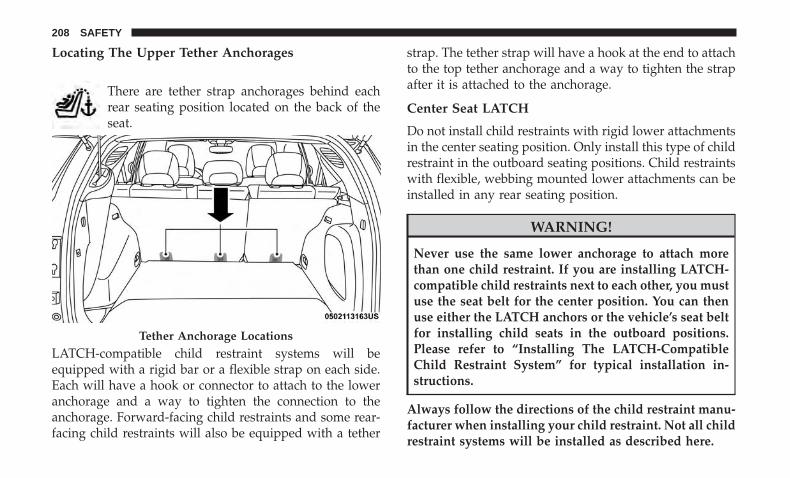
Locating The Upper Tether Anchorages
There are tether strap anchorages behind eachrear seating position located on the back of theseat.
LATCH-compatible child restraint systems will beequipped with a rigid bar or a flexible strap on each side.Each will have a hook or connector to attach to the loweranchorage and a way to tighten the connection to theanchorage. Forward-facing child restraints and some rear-facing child restraints will also be equipped with a tether
strap. The tether strap will have a hook at the end to attachto the top tether anchorage and a way to tighten the strapafter it is attached to the anchorage.
Center Seat LATCH
Do not install child restraints with rigid lower attachmentsin the center seating position. Only install this type of childrestraint in the outboard seating positions. Child restraintswith flexible, webbing mounted lower attachments can beinstalled in any rear seating position.
WARNING!
Never use the same lower anchorage to attach morethan one child restraint. If you are installing LATCH-compatible child restraints next to each other, you mustuse the seat belt for the center position. You can thenuse either the LATCH anchors or the vehicle’s seat beltfor installing child seats in the outboard positions.Please refer to “Installing The LATCH-CompatibleChild Restraint System” for typical installation in-structions.
Always follow the directions of the child restraint manu-facturer when installing your child restraint. Not all childrestraint systems will be installed as described here.
Tether Anchorage Locations
208 SAFETY

To Install A LATCH-Compatible Child Restraint
If the selected seating position has a Switchable AutomaticLocking Retractor (ALR) seat belt, stow the seat belt,following the instructions below. See the section “InstallingChild Restraints Using the Vehicle Seat Belt” to check whattype of seat belt each seating position has.
1. Loosen the adjusters on the lower straps and on thetether strap of the child seat so that you can more easilyattach the hooks or connectors to the vehicle anchor-ages.
2. Place the child seat between the lower anchorages forthat seating position. For some second row seats, youmay need to recline the seat and / or raise the headrestraint to get a better fit. If the rear seat can be movedforward and rearward in the vehicle, you may wish tomove it to its rear-most position to make room for thechild seat. You may also move the front seat forward toallow more room for the child seat.
3. Attach the lower hooks or connectors of the childrestraint to the lower anchorages in the selected seatingposition.
4. If the child restraint has a tether strap, connect it to thetop tether anchorage. See the section “Installing ChildRestraints Using the Top Tether Anchorage” for direc-tions to attach a tether anchor.
5. Tighten all of the straps as you push the child restraintrearward and downward into the seat. Remove slack inthe straps according to the child restraint manufactur-er’s instructions.
6. Test that the child restraint is installed tightly by pullingback and forth on the child seat at the belt path. Itshould not move more than 1 inch (25.4 mm) in anydirection.
5
SAFETY 209

How To Stow An Unused Switchable-ALR (ALR)Seat Belt:
When using the LATCH attaching system to install a childrestraint, stow all ALR seat belts that are not being used byother occupants or being used to secure child restraints. Anunused belt could injure a child if they play with it andaccidentally lock the seat belt retractor. Before installing achild restraint using the LATCH system, buckle the seatbelt behind the child restraint and out of the child’s reach.If the buckled seat belt interferes with the child restraintinstallation, instead of buckling it behind the child re-straint, route the seat belt through the child restraint beltpath and then buckle it. Do not lock the seat belt. Remindall children in the vehicle that the seat belts are not toys andthat they should not play with them.
WARNING!
• Improper installation of a child restraint to theLATCH anchorages can lead to failure of the re-straint. The child could be badly injured or killed.Follow the child restraint manufacturer’s directionsexactly when installing an infant or child restraint.
(Continued)
WARNING! (Continued)• Child restraint anchorages are designed to withstand
only those loads imposed by correctly-fitted childrestraints. Under no circumstances are they to beused for adult seat belts, harnesses, or for attachingother items or equipment to the vehicle.
Installing Child Restraints Using The Vehicle SeatBelt
Child restraint systems are designed to be secured invehicle seats by lap belts or the lap belt portion of alap/shoulder belt.
WARNING!
• Improper installation or failure to properly secure achild restraint can lead to failure of the restraint. Thechild could be badly injured or killed.
• Follow the child restraint manufacturer’s directionsexactly when installing an infant or child restraint.
210 SAFETY

The seat belts in the passenger seating positions areequipped with a Switchable Automatic Locking Retractor(ALR) that is designed to keep the lap portion of the seatbelt tight around the child restraint so that it is notnecessary to use a locking clip. The ALR retractor can be“switched” into a locked mode by pulling all of thewebbing out of the retractor and then letting the webbingretract back into the retractor. If it is locked, the ALR willmake a clicking noise while the webbing is pulled back intothe retractor. Refer to the “Automatic Locking Mode”description in “Switchable Automatic Locking Retractors(ALR)” under “Occupant Restraint Systems” for additionalinformation on ALR.
Please see the table below and the following sections formore information.
Lap/Shoulder Belt Systems For Installing ChildRestraints In This Vehicle
Automatic Locking Retractor (ALR) Locations
• ALR = Switchable Automatic Locking Retractor
• Top Tether Anchorage Symbol
5
SAFETY 211

Frequently Asked Questions About Installing Child Restraints With Seat BeltsWhat is the weight limit (child’s weight + weightof the child restraint) for using the Tether Anchorwith the seat belt to attach a forward facing child
restraint?
Weight limitof the Child
Restraint
Always use the tether anchor when using theseat belt to install a forward facing child re-
straint, up to the recommended weight limit ofthe child restraint.
Can the rear-facing child restraint touch the backof the front passenger seat?
Yes Contact between the front passenger seat and thechild restraint is allowed, if the child restraint
manufacturer also allows contact.Can the head restraints be removed? Yes The head restraints can be removed in every seat-
ing position.Can the buckle stalk be twisted to tighten theseat belt against the belt path of the child re-
straint?
No Do not twist the buckle stalk in a seating positionwith an ALR retractor.
Installing A Child Restraint With A SwitchableAutomatic Locking Retractor (ALR):
Child restraint systems are designed to be secured invehicle seats by lap belts or the lap belt portion of alap/shoulder belt.
WARNING!
• Improper installation or failure to properly secure achild restraint can lead to failure of the restraint. Thechild could be badly injured or killed.
• Follow the child restraint manufacturer’s directionsexactly when installing an infant or child restraint.
212 SAFETY

1. Place the child seat in the center of the seating position.For some second row seats, you may need to recline theseat and/or raise the head restraint to get a better fit. Ifthe rear seat can be moved forward and rearward in thevehicle, you may wish to move it to its rear-mostposition to make room for the child seat. You may alsomove the front seat forward to allow more room for thechild seat.
2. Pull enough of the seat belt webbing from the retractorto pass it through the belt path of the child restraint. Donot twist the belt webbing in the belt path.
3. Slide the latch plate into the buckle until you hear a“click.”
4. Pull on the webbing to make the lap portion tightagainst the child seat.
5. To lock the seat belt, pull down on the shoulder part ofthe belt until you have pulled all the seat belt webbingout of the retractor. Then, allow the webbing to retractback into the retractor. As the webbing retracts, you willhear a clicking sound. This means the seat belt is now inthe Automatic Locking mode.
6. Try to pull the webbing out of the retractor. If it islocked, you should not be able to pull out any webbing.If the retractor is not locked, repeat step 5.
7. Finally, pull up on any excess webbing to tighten the lapportion around the child restraint while you push thechild restraint rearward and downward into the vehicleseat.
8. If the child restraint has a top tether strap and theseating position has a top tether anchorage, connect thetether strap to the anchorage and tighten the tetherstrap. See the section “Installing Child Restraints Usingthe Top Tether Anchorage” for directions to attach atether anchor.
9. Test that the child restraint is installed tightly by pullingback and forth on the child seat at the belt path. Itshould not move more than 1 inch (25.4 mm) in anydirection.
Any seat belt system will loosen with time, so check thebelt occasionally, and pull it tight if necessary.
5
SAFETY 213

Installing Child Restraints Using The Top TetherAnchorage:
WARNING!
Do not attach a tether strap for a rear-facing car seat toany location in front of the car seat, including the seatframe or a tether anchorage. Only attach the tetherstrap of a rear-facing car seat to the tether anchoragethat is approved for that seating position, locatedbehind the top of the vehicle seat. See the section“Lower Anchors and Tethers for CHildren (LATCH)Restraint System” for the location of approved tetheranchorages in your vehicle.
1. Look behind the seating position where you plan toinstall the child restraint to find the tether anchorage.You may need to move the seat forward to providebetter access to the tether anchorage. If there is no toptether anchorage for that seating position, move thechild restraint to another position in the vehicle if one isavailable.
2. Route the tether strap to provide the most direct path forthe strap between the anchor and the child seat. If yourvehicle is equipped with adjustable rear head restraints,raise the head restraint, and where possible, route thetether strap under the head restraint and between thetwo posts. If not possible, lower the head restraint andpass the tether strap around the outboard side of thehead restraint.
3. Attach the tether strap hook of the child restraint to thetop tether anchorage as shown in the diagram.
4. Remove slack in the tether strap according to the childrestraint manufacturer’s instructions.
214 SAFETY

WARNING!
• An incorrectly anchored tether strap could lead toincreased head motion and possible injury to thechild. Use only the anchorage position directly be-hind the child seat to secure a child restraint toptether strap.
• If your vehicle is equipped with a split rear seat,make sure the tether strap does not slip into theopening between the seatbacks as you remove slackin the strap.
Transporting Pets
Air Bags deploying in the front seat could harm your pet. Anunrestrained pet will be thrown about and possibly injured,or injure a passenger during panic braking or in a collision.
Pets should be restrained in the rear seat in pet harnesses orpet carriers that are secured by seat belts.
SAFETY TIPS
Transporting Passengers
NEVER TRANSPORT PASSENGERS IN THE CARGO AREA.
WARNING!
• Do not leave children or animals inside parkedvehicles in hot weather. Interior heat build-up maycause serious injury or death.
• It is extremely dangerous to ride in a cargo area,inside or outside of a vehicle. In a collision, peopleriding in these areas are more likely to be seriouslyinjured or killed.
• Do not allow people to ride in any area of yourvehicle that is not equipped with seats and seat belts.
• Be sure everyone in your vehicle is in a seat andusing a seat belt properly.
Rear Seat Tether Anchors
5
SAFETY 215

Exhaust Gas
WARNING!
Exhaust gases can injure or kill. They contain carbonmonoxide (CO), which is colorless and odorless.Breathing it can make you unconscious and can even-tually poison you. To avoid breathing (CO), followthese safety tips:• Do not run the engine in a closed garage or in
confined areas any longer than needed to move yourvehicle in or out of the area.
• If you are required to drive with the trunk/liftgate/rear doors open, make sure that all windows areclosed and the climate control BLOWER switch is setat high speed. DO NOT use the recirculation mode.
• If it is necessary to sit in a parked vehicle with theengine running, adjust your heating or cooling con-trols to force outside air into the vehicle. Set theblower at high speed.
The best protection against carbon monoxide entry into thevehicle body is a properly maintained engine exhaustsystem.
Whenever a change is noticed in the sound of the exhaustsystem, when exhaust fumes can be detected inside the
vehicle, or when the underside or rear of the vehicle isdamaged, have a competent mechanic inspect the completeexhaust system and adjacent body areas for broken, dam-aged, deteriorated, or mispositioned parts. Open seams orloose connections could permit exhaust fumes to seep intothe passenger compartment. In addition, inspect the ex-haust system each time the vehicle is raised for lubricationor oil change. Replace as required.
Safety Checks You Should Make Inside The Vehicle
Seat Belts
Inspect the seat belt system periodically, checking for cuts,frays, and loose parts. Damaged parts must be replacedimmediately. Do not disassemble or modify the system.
Front seat belt assemblies must be replaced after a collision.Rear seat belt assemblies must be replaced after a collisionif they have been damaged (i.e., bent retractor, torn web-bing, etc.). If there is any question regarding seat belt orretractor condition, replace the seat belt.
Air Bag Warning Light
The Air Bag warning light will turn on for four toeight seconds as a bulb check when the ignition switchis first turned to ON/RUN. If the light is either not onduring starting, stays on, or turns on while driving,
216 SAFETY

have the system inspected at your authorized dealer assoon as possible. After the bulb check, this light willilluminate with a single chime when a fault with the AirBag System has been detected. It will stay on until thefault is removed. If the light comes on intermittently orremains on while driving, have your authorized dealerservice the vehicle immediately. Refer to “OccupantRestraint Systems” in “Safety” for further information.
Defroster
Check operation by selecting the defrost mode and placethe blower control on high speed. You should be able tofeel the air directed against the windshield. See yourauthorized dealer for service if your defroster is inoper-able.
Floor Mat Safety Information
Always use floor mats designed to fit your vehicle. Onlyuse a floor mat that does not interfere with the operation ofthe accelerator, brake or clutch pedals. Only use a floor matthat is securely attached using the floor mat fasteners so itcannot slip out of position and interfere with the accelera-tor, brake or clutch pedals or impair safe operation of yourvehicle in other ways.
WARNING!
An improperly attached, damaged, folded, or stackedfloor mat, or damaged floor mat fasteners may causeyour floor mat to interfere with the accelerator, brake,or clutch pedals and cause a loss of vehicle control. Toprevent SERIOUS INJURY or DEATH:• ALWAYS securely attach your floor mat using the
floor mat fasteners. DO NOT install your floor matupside down or turn your floor mat over. Lightly pullto confirm mat is secured using the floor mat fasten-ers on a regular basis.
• ALWAYS REMOVE THE EXISTING FLOOR MATFROM THE VEHICLE before installing any otherfloor mat. NEVER install or stack an additional floormat on top of an existing floor mat.
• ONLY install floor mats designed to fit your vehicle.NEVER install a floor mat that cannot be properlyattached and secured to your vehicle. If a floor matneeds to be replaced, only use a FCA approved floormat for the specific make, model, and year of yourvehicle.
(Continued)
5
SAFETY 217
WARNING! (Continued)• ONLY use the driver’s side floor mat on the driver’s
side floor area. To check for interference, with thevehicle properly parked with the engine off, fullydepress the accelerator, the brake, and the clutchpedal (if present) to check for interference. If yourfloor mat interferes with the operation of any pedal,or is not secure to the floor, remove the floor matfrom the vehicle and place the floor mat in yourtrunk.
• ONLY use the passenger’s side floor mat on thepassenger’s side floor area.
• ALWAYS make sure objects cannot fall or slide intothe driver’s side floor area when the vehicle ismoving. Objects can become trapped under accelera-tor, brake, or clutch pedals and could cause a loss ofvehicle control.
• NEVER place any objects under the floor mat (e.g.,towels, keys, etc.). These objects could change theposition of the floor mat and may cause interferencewith the accelerator, brake, or clutch pedals.
• If the vehicle carpet has been removed and re-installed, always properly attach carpet to the floor
(Continued)
WARNING! (Continued)and check the floor mat fasteners are secure to thevehicle carpet. Fully depress each pedal to check forinterference with the accelerator, brake, or clutchpedals then re-install the floor mats.
• It is recommended to only use mild soap and waterto clean your floor mats. After cleaning, always checkyour floor mat has been properly installed and issecured to your vehicle using the floor mat fastenersby lightly pulling mat.
Periodic Safety Checks You Should Make OutsideThe Vehicle
Tires
Examine tires for excessive tread wear and uneven wearpatterns. Check for stones, nails, glass, or other objectslodged in the tread or sidewall. Inspect the tread for cutsand cracks. Inspect sidewalls for cuts, cracks, and bulges.Check the wheel nuts for tightness. Check the tires (includ-ing spare) for proper cold inflation pressure.
218 SAFETY
Lights
Have someone observe the operation of brake lights andexterior lights while you work the controls. Check turnsignal and high beam indicator lights on the instrumentpanel.
Door Latches
Check for proper closing, latching, and locking.
Fluid Leaks
Check area under the vehicle after overnight parking forfuel, coolant, oil, or other fluid leaks. Also, if gasolinefumes are detected or if fuel, or brake fluid leaks aresuspected. The cause should be located and correctedimmediately.
5
SAFETY 219


STARTING AND OPERATING
CONTENTS� STARTING THE ENGINE . . . . . . . . . . . . . . . . . .224
▫ Normal Starting . . . . . . . . . . . . . . . . . . . . . . .224
▫ Cold Weather Operation(Below –22°F Or −30°C) . . . . . . . . . . . . . . . . . .226
▫ Extended Park Starting . . . . . . . . . . . . . . . . . . .226
▫ After Starting — Warming Up The Engine . . . . .227
▫ If Engine Fails To Start . . . . . . . . . . . . . . . . . .227
▫ Stopping The Engine . . . . . . . . . . . . . . . . . . . .228
� ENGINE BLOCK HEATER — IF EQUIPPED . . . .228
� ENGINE BREAK-IN RECOMMENDATIONS . . . .229
� PARK BRAKE . . . . . . . . . . . . . . . . . . . . . . . . . .230
▫ Electric Park Brake (EPB) . . . . . . . . . . . . . . . . .230
� MANUAL TRANSMISSION — IF EQUIPPED . . .235
▫ Shifting . . . . . . . . . . . . . . . . . . . . . . . . . . . . . .236
▫ Downshifting. . . . . . . . . . . . . . . . . . . . . . . . . .237
▫ Parking . . . . . . . . . . . . . . . . . . . . . . . . . . . . . .238
� AUTOMATIC TRANSMISSION —IF EQUIPPED . . . . . . . . . . . . . . . . . . . . . . . . . .239
▫ Ignition Park Interlock . . . . . . . . . . . . . . . . . . .240
▫ Brake/Transmission Shift Interlock System . . . .240
▫ Six-Speed Or Nine-Speed AutomaticTransmission . . . . . . . . . . . . . . . . . . . . . . . . . .241
� FOUR-WHEEL DRIVE OPERATION —IF EQUIPPED . . . . . . . . . . . . . . . . . . . . . . . . . . .248
▫ Jeep Active Drive . . . . . . . . . . . . . . . . . . . . . . .248
� SELEC-TERRAIN — IF EQUIPPED. . . . . . . . . . . .250
▫ Mode Selection Guide. . . . . . . . . . . . . . . . . . . .251
� POWER STEERING. . . . . . . . . . . . . . . . . . . . . . .252
� STOP/START SYSTEM — IF EQUIPPED. . . . . . . .253
6

▫ Automatic Mode . . . . . . . . . . . . . . . . . . . . . . .253
▫ Possible Reasons The Engine Does NotAutostop . . . . . . . . . . . . . . . . . . . . . . . . . . . . .254
▫ To Start The Engine While In Autostop Mode . . .255
▫ To Manually Turn Off The Stop/Start System . .255
▫ To Manually Turn On The Stop/Start System . . .256
▫ System Malfunction . . . . . . . . . . . . . . . . . . . . .256
� SPEED CONTROL — IF EQUIPPED . . . . . . . . . .256
▫ To Activate . . . . . . . . . . . . . . . . . . . . . . . . . . .257
▫ To Set A Desired Speed. . . . . . . . . . . . . . . . . . .257
▫ To Vary The Speed Setting . . . . . . . . . . . . . . . .257
▫ To Accelerate For Passing . . . . . . . . . . . . . . . . .259
▫ To Resume Speed . . . . . . . . . . . . . . . . . . . . . .259
▫ To Deactivate . . . . . . . . . . . . . . . . . . . . . . . . .259
� PARKSENSE REAR PARK ASSIST —IF EQUIPPED . . . . . . . . . . . . . . . . . . . . . . . . . .259
▫ ParkSense Sensors . . . . . . . . . . . . . . . . . . . . . .259
▫ ParkSense Warning Display. . . . . . . . . . . . . . . .260
▫ ParkSense Display . . . . . . . . . . . . . . . . . . . . . .260
▫ Enabling And Disabling ParkSense . . . . . . . . . .264
▫ Service The ParkSense Rear Park AssistSystem . . . . . . . . . . . . . . . . . . . . . . . . . . . . . .264
▫ Cleaning The ParkSense System. . . . . . . . . . . . .264
▫ ParkSense System Usage Precautions . . . . . . . . .265
� LANESENSE — IF EQUIPPED . . . . . . . . . . . . . .266
▫ LaneSense Operation . . . . . . . . . . . . . . . . . . . .266
▫ Turning LaneSense On Or Off . . . . . . . . . . . . . .267
▫ LaneSense Warning Message . . . . . . . . . . . . . . .267
▫ Changing LaneSense Status . . . . . . . . . . . . . . . .272
� PARKVIEW REAR BACK UP CAMERA . . . . . . . .273
� REFUELING THE VEHICLE . . . . . . . . . . . . . . . .274
� VEHICLE LOADING . . . . . . . . . . . . . . . . . . . . .276
▫ Certification Label . . . . . . . . . . . . . . . . . . . . . .276
� TRAILER TOWING . . . . . . . . . . . . . . . . . . . . . .278
▫ Common Towing Definitions. . . . . . . . . . . . . . .278
222 STARTING AND OPERATING

▫ Trailer Towing Weights (Maximum TrailerWeight Ratings) . . . . . . . . . . . . . . . . . . . . . . .280
▫ Trailer And Tongue Weight . . . . . . . . . . . . . . .281
▫ Towing Requirements . . . . . . . . . . . . . . . . . . .281
▫ Towing Tips . . . . . . . . . . . . . . . . . . . . . . . . . .285
� RECREATIONAL TOWING (BEHINDMOTORHOME, ETC.) . . . . . . . . . . . . . . . . . . . .286
▫ Towing This Vehicle Behind Another Vehicle . . .286
▫ Recreational Towing — Front-Wheel Drive(FWD) Models . . . . . . . . . . . . . . . . . . . . . . . . .287
▫ Recreational Towing — 4X4 Models . . . . . . . . . .287
� DRIVING TIPS . . . . . . . . . . . . . . . . . . . . . . . . . .288
▫ On-Road Driving Tips . . . . . . . . . . . . . . . . . . .288
▫ Off-Road Driving Tips . . . . . . . . . . . . . . . . . . .288
6
STARTING AND OPERATING 223

STARTING THE ENGINE
Before starting your vehicle, adjust your seat, adjust bothinside and outside mirrors, and fasten your seat belts.
WARNING!
• When exiting the vehicle, always remove the key fobfrom the vehicle and lock your vehicle.
• Never leave children alone in a vehicle, or withaccess to an unlocked vehicle.
• Allowing children to be in a vehicle unattended isdangerous for a number of reasons. A child or otherscould be seriously or fatally injured. Childrenshould be warned not to touch the parking brake,brake pedal or the transmission gear selector.
• Do not leave the key fob in or near the vehicle, or ina location accessible to children, and do not leave theignition of a vehicle equipped with Keyless Enter-N-Go in the ACC or ON/RUN mode. A child couldoperate power windows, other controls, or move thevehicle.
• Do not leave children or animals inside parkedvehicles in hot weather. Interior heat build-up maycause serious injury or death.
Start the engine with the gear selector in the NEUTRAL orPARK position. Apply the brake before shifting to anydriving range.
Normal Starting
NOTE: Normal starting of either a cold or a warm engine isobtained without pumping or pressing the accelerator pedal.
Cycle the ignition switch to the START position and releasewhen the engine starts. If the engine fails to start within 10seconds, cycle the ignition switch to the LOCK/OFF posi-tion, wait 10 to 15 seconds, then repeat the “NormalStarting” procedure.
Tip Start Feature
Cycle the ignition switch to START position and release itas soon as the starter engages. The starter motor willcontinue to run, and will automatically disengage itselfwhen the engine is running. If the engine fails to start, cyclethe ignition switch to the OFF position, wait 10 to 15seconds, then repeat the “Normal Starting” procedure.
Automatic Transmission
The gear selector must be in the NEUTRAL or PARKposition before you can start the engine. Apply the brakesbefore shifting into any driving gear.
224 STARTING AND OPERATING
CAUTION!
Damage to the transmission may occur if the followingprecautions are not observed:• Do not shift between PARK, REVERSE, NEUTRAL,
or DRIVE when the engine is above idle speed.• Shift into or out of PARK or REVERSE only after the
vehicle has come to a complete stop.• Before shifting into any gear, make sure your foot is
firmly on the brake pedal.
Keyless Enter-N-Go Functions — Using The ENGINESTART/STOP Button
1. The transmission must be in PARK or NEUTRAL.
2. Press and hold the brake pedal while pushing theENGINE START/STOP button once.
3. The system takes over and attempts to start the vehicle.If the vehicle fails to start, the starter will disengageautomatically after 10 seconds.
4. If you wish to stop the cranking of the engine prior tothe engine starting, push the button again.
NOTE: Normal starting of either a cold or a warm engine isobtained without pumping or pressing the accelerator pedal.
Keyless Enter-N-Go — With Driver’s Foot OFF The BrakePedal/Clutch Pedal (In PARK Or NEUTRAL Position)
The Keyless Enter-N-Go feature operates similar to anignition switch. It has three positions, OFF, RUN, andSTART. To change the ignition switch positions withoutstarting the vehicle and use the accessories follow thesesteps starting with the ignition switch in the OFF position:
1. Push the ENGINE START/STOP button once to changethe ignition switch to the RUN position,
2. Push the ENGINE START/STOP button a second timeto change the ignition switch to the OFF position,
Manual Transmission
The gear selector must be in the NEUTRAL position beforeyou can start the engine. Apply the brakes before shiftinginto any driving gear.
Keyless Enter-N-Go Functions — Using The ENGINESTART/STOP Button
1. The transmission must be in NEUTRAL.
2. Press and hold the clutch pedal while pushing theENGINE START/STOP button once.
6
STARTING AND OPERATING 225

3. The system takes over and attempts to start the vehicle.If the vehicle fails to start, the starter will disengageautomatically after 10 seconds.
4. If you wish to stop the cranking of the engine prior tothe engine starting, push the button again.
NOTE: Normal starting of either a cold or a warm engine isobtained without pumping or pressing the accelerator pedal.
Keyless Enter-N-Go Functions — With Driver’s Foot OFFThe Brake Pedal/Clutch Pedal (In PARK Or NEUTRALPosition)
The Keyless Enter-N-Go feature operates similar to anignition switch. It has three positions, OFF, RUN, andSTART. To change the ignition switch positions withoutstarting the vehicle and use the accessories follow thesesteps starting with the ignition switch in the OFF position:
1. Push the ENGINE START/STOP button once to changethe ignition switch to the RUN position,
2. Push the ENGINE START/STOP button a second timeto change the ignition switch to the OFF position,
Cold Weather Operation (Below –22°F Or −30°C)
To ensure reliable starting at these temperatures, use of anexternally powered electric engine block heater (availablefrom your authorized dealer) is recommended.
Extended Park Starting
NOTE: Extended Park condition occurs when the vehiclehas not been started or driven for at least 30 days.
1. Install a battery charger or jumper cables to the batteryto ensure a full battery charge during the crank cycle.
2. Cycle the ignition in the START position and release itwhen the engine starts.
3. If the engine fails to start within ten seconds, cycle theignition to the OFF position, wait five seconds to allowthe starter to cool, then repeat the Extended ParkStarting procedure.
4. If the engine fails to start after eight attempts, allow thestarter to cool for at least 10 minutes, then repeat theprocedure.
226 STARTING AND OPERATING

CAUTION!
To prevent damage to the starter, do not crank continu-ously for more than 10 seconds at a time. Wait 10 to 15seconds before trying again.
After Starting — Warming Up The Engine
The idle speed is controlled automatically and it willdecrease as the engine warms up.
If Engine Fails To Start
If the engine fails to start after you have followed the�Normal Starting� or �Extreme Cold Weather� procedure,and has not experienced an extended park condition asidentified in �Extended Park Starting� procedure it may beflooded. Push the accelerator pedal all the way to the floorand hold it there. Crank the engine for no more than 15seconds. This should clear any excess fuel in case theengine is flooded. Leave the ignition key in the RUNposition, release the accelerator pedal and repeat the “Nor-mal Starting” procedure.
CAUTION!
To prevent damage to the starter, do not continuouslycrank the engine for more than 25 seconds at a time.Wait 60 seconds before trying again.
WARNING!
• Never pour fuel or other flammable liquid into thethrottle body air inlet opening in an attempt to startthe vehicle. This could result in flash fire causingserious personal injury.
• Do not attempt to push or tow your vehicle to get itstarted. Vehicles equipped with an automatic trans-mission cannot be started this way. Unburned fuelcould enter the catalytic converter and once theengine has started, ignite and damage the converterand vehicle.
• If the vehicle has a discharged battery, booster cablesmay be used to obtain a start from a booster batteryor the battery in another vehicle. This type of startcan be dangerous if done improperly. Refer to “JumpStarting Procedure” in “In Case Of Emergency” forfurther information.
6
STARTING AND OPERATING 227

Stopping The Engine
Vehicles Equipped With Electronic Key (Keyless Enter-N-Go):
To shut off the engine with vehicle speed greater than5 mph (8 km/h), you must push and hold the ignition orpush the START/STOP button three times consecutivelywithin a few seconds. The engine will shut down, and theignition will be placed in the RUN position.
Turning Off the car (placing the ignition from the RUNposition to the STOP position), the power supply to theaccessories are maintained for a period of three minutes.
Opening the driver side door with the ignition in RUN willsound a short chime that reminds the driver to place theignition to STOP.
When the ignition is in the STOP/OFF position, the win-dow switches remains active for three minutes. Opening afront door will cancel this function.
After severe driving, idle the engine to allow the tempera-ture inside the engine compartment to cool before shuttingoff the engine.
ENGINE BLOCK HEATER — IF EQUIPPED
The engine block heater warms the engine and permitsquicker starts in cold weather.
Connect the cord to a 110-115 Volt AC electrical outlet witha grounded, three-wire extension cord.
For ambient temperatures below 0°F (-18°C), the engineblock heater is recommended. For ambient temperaturesbelow -20°F (-29°C), the engine block heater is required.
The engine block heater cord is routed under the hood,behind to the driver’s side headlamp. Follow the stepsbelow to properly use the engine block heater:
1. Locate the engine block heater cord (behind the driver’sside headlamp).
2. Undo the Velcro strap that secures the heater cord inplace.
3. Pull the cord to the front of the vehicle and plug it intoa grounded, three-wire extension cord.
4. After the vehicle is running, reattach the cord to theVelcro strap, and properly stow away behind the driv-er’s side headlamp.
228 STARTING AND OPERATING

NOTE:
• The engine block heater cord is a factory installedoption. If your vehicle is not equipped, heater cords areavailable from your authorized Mopar dealer.
• The engine block heater will require 110 Volts AC and6.5 Amps to activate the heater element.
• The engine block heater must be plugged in at least onehour to have an adequate warming effect on the engine.
WARNING!
Remember to disconnect the engine block heater cordbefore driving. Damage to the 110-115 Volt electricalcord could cause electrocution.
ENGINE BREAK-IN RECOMMENDATIONS
A long break-in period is not required for the engine anddrivetrain (transmission and axle) in your vehicle.
Drive moderately during the first 300 miles (500 km). Afterthe initial 60 miles (100 km), speeds up to 50 or 55 mph (80or 90 km/h) are desirable.
While cruising, brief full-throttle acceleration within thelimits of local traffic laws contributes to a good break-in.Wide-open throttle acceleration in low gear can be detri-mental and should be avoided.
The engine oil installed in the engine at the factory is ahigh-quality energy conserving type lubricant. Oil changesshould be consistent with anticipated climate conditionsunder which vehicle operations will occur. For the recom-mended viscosity and quality grades, refer to “DealerService” in “Servicing And Maintenance”.
CAUTION!
Never use Non-Detergent Oil or Straight Mineral Oilin the engine or damage may result.
NOTE: A new engine may consume some oil during itsfirst few thousand miles (kilometers) of operation. Thisshould be considered a normal part of the break-in and notinterpreted as a problem.
6
STARTING AND OPERATING 229

PARK BRAKE
Electric Park Brake (EPB)
Your vehicle is equipped with an Electric Park BrakeSystem (EPB) that offers simple operation, and someadditional features that make the parking brake moreconvenient and useful.
The parking brake is primarily intended to prevent thevehicle from rolling while parked. Before leaving thevehicle, make sure that the park brake is applied. Also, becertain to leave the transmission in PARK.
You can engage the park brake in two ways:
• Manually, by applying the park brake switch.
• Automatically, by enabling the Auto Park Brake featurein the customer programmable features section of theUconnect settings.
The park brake switch is located in the center console.
To apply the park brake manually, pull up on the switchmomentarily. You may hear a slight whirring sound fromthe back of the vehicle while the park brake engages. Oncethe park brake is fully engaged, the BRAKE warning lampin the instrument cluster and an indicator on the switchwill illuminate. If your foot is on the brake pedal while youapply the park brake, you may notice a small amount ofbrake pedal movement. The park brake can be appliedeven when the ignition switch is OFF but the BRAKEwarning lamp will not illuminate, however, it can only bereleased when the ignition switch is in the ON/RUNposition.
Electric Park Brake Switch
230 STARTING AND OPERATING

NOTE: The EPB fault lamp will illuminate if the EPBswitch is held for longer than 60 seconds in either thereleased or applied position. The light will extinguish uponreleasing the switch.
If the Auto Park Brake feature is enabled, the parking brakewill automatically engage whenever the transmission isplaced into PARK, or with a manual transmission, whenthe ignition switch is turned OFF. If your foot is on thebrake pedal, you may notice a small amount of brake pedalmovement while the park brake is engaging.
The park brake will release automatically when the igni-tion switch is ON, the transmission is in DRIVE or RE-VERSE, the driver seat belt is buckled, and an attempt ismade to drive away.
To release the park brake manually, the ignition switchmust be in the ON/RUN position. Put your foot on thebrake pedal, then push the park brake switch downmomentarily. You may hear a slight whirring sound fromthe back of the car while the parking brake disengages. Youmay also notice a small amount of movement in the brakepedal. Once the park brake is fully disengaged, the BRAKEwarning lamp in the instrument cluster and the LEDindicator on the switch will extinguish.
NOTE: When parking on a hill, it is important to turn thefront wheels toward the curb on a downhill grade andaway from the curb on an uphill grade. Apply the parkbrake before placing the gear selector in PARK, otherwisethe load on the transmission locking mechanism may makeit difficult to move the gear selector out of PARK. Theparking brake should always be applied whenever thedriver is not in the vehicle.
WARNING!
• Do not rely on the parking brake to operate effec-tively if the rear brakes have been immersed in wateror mud.
• Never use the PARK position as a substitute for theparking brake. Always apply the parking brake fullywhen parked to guard against vehicle movement andpossible injury or damage.
• When leaving the vehicle, always remove the key fobfrom the ignition and lock your vehicle.
• Never leave children alone in a vehicle, or withaccess to an unlocked vehicle. Allowing children tobe in a vehicle unattended is dangerous for a numberof reasons. A child or others could be seriously or
(Continued)
6
STARTING AND OPERATING 231

WARNING! (Continued)fatally injured. Children should be warned not totouch the parking brake, brake pedal or the gearselector.
• Do not leave the key fob in or near the vehicle, or ina location accessible to children, and do not leave theignition of a vehicle equipped with Keyless Enter-N-Go in the ACC or ON/RUN mode. A child couldoperate power windows, other controls, or move thevehicle.
• Be sure the parking brake is fully disengaged beforedriving; failure to do so can lead to brake failure anda collision.
• Always fully apply the parking brake when leavingyour vehicle, or it may roll and cause damage orinjury. Also be certain to leave the transmission inPARK. Failure to do so may allow the vehicle to rolland cause damage or injury.
CAUTION!
If the Brake System Warning Light remains on with theparking brake released, a brake system malfunction is
(Continued)
CAUTION! (Continued)indicated. Have the brake system serviced by an au-thorized dealer immediately.
If exceptional circumstances should make it necessary toengage the park brake while the vehicle is in motion,maintain upward pressure on the electric park brakeswitch for as long as engagement is desired. The BRAKEwarning lamp will illuminate, and a continuous chime willsound. The rear stop lamps will also be illuminated auto-matically while the vehicle remains in motion.
To disengage the park brake while the vehicle is in motion,release the switch. If the vehicle is brought to a completestop using the parking brake, when the vehicle reachesapproximately 3 mph, (5 km/h) the parking brake willremain engaged.
WARNING!
Driving the vehicle with the parking brake engaged, orrepeated use of the parking brake to slow the vehiclemay cause serious damage to the brake system; failureto do so can lead to brake failure and a collision.
232 STARTING AND OPERATING

In the unlikely event of a malfunction of the Electric ParkBrake system, a yellow EPB fault lamp will illuminate. Thismay be accompanied by the BRAKE warning lamp flash-ing. In this event, urgent service of the electric park brakesystem is required. Do not rely on the parking brake tohold the vehicle stationary.
Auto Park Brake
The EPB can be programmed to be applied automaticallywhenever the vehicle speed is below 1.9 mph (3 km/h) andthe automatic transmission is placed in PARK, or with amanual transmission, whenever the ignition switch is inthe OFF position. Auto Park Brake is enabled and disabledby customer selection through the Customer Program-mable Features section of the Uconnect Settings.
Any single Auto Park Brake application can be bypassedby pushing the EPB switch to the release position while thetransmission is placed in PARK (automatic transmission)and the ignition is in the ON/RUN position.
SafeHold
SafeHold is a safety feature of the EPB system that willengage the park brake automatically if the vehicle is leftunsecured while the ignition switch is in ON/RUN.
For automatic transmissions, the EPB will automaticallyengage if all of the following conditions are met:
• Vehicle speed is below 1.9 mph (3 km/h).• There is no attempt to depress the brake pedal or
accelerator pedal.• The seat belt is unbuckled.• The driver door is open.• The vehicle is not in the PARK position.
For manual transmissions, the EPB will automaticallyengage if all of the following conditions are met:
• Vehicle speed is below 1.9 mph (3 km/h).• There is no attempt to depress the brake pedal or
accelerator pedal.• The clutch pedal is not pressed.• The seat belt is unbuckled.• The driver door is open.
SafeHold can be temporarily bypassed by pushing the EPBSwitch while the driver door is open and the brake pedal ispressed. Once manually bypassed, SafeHold will be en-abled again once the vehicle reaches 12 mph (20 km/h) orthe ignition is turned to the OFF position and back toON/RUN again.
6
STARTING AND OPERATING 233

Brake Service Mode
We recommend having your brakes serviced by your autho-rized dealer. You should only make repairs for which youhave the knowledge and the right equipment. You shouldonly enter Brake Service Mode during brake service.
When servicing your rear brakes, it may be necessary foryou or your technician to push the rear piston into the rearcaliper bore. With the electric park brake system, this canonly be done after retracting the EPB actuator. The actuatorretraction can be done easily by entering the Brake ServiceMode through the Uconnect Settings in your vehicle. Thismenu based system will guide you through the stepsnecessary to retract the EPB actuator in order to performrear brake service.
Service Mode has requirements that must be met in orderto be activated:
• The vehicle must be at a standstill.
• The parking brake must be disabled.
• The transmission must be in park or neutral.
• The EPB switch not activated.
• The vehicle in ignition ON/RUN position.
• The brake pedal not pressed.
While in service mode, the EPB fault lamp will flashcontinuously while the ignition switch is ON/RUN.
NOTE: A dedicated message will appear in the instrumentcluster display if Brake Service Mode cannot be activated.
When brake service work is complete, the following stepsmust be followed to reset the parking brake system tonormal operation:
• Ensure the vehicle is at a standstill.
• Press the brake pedal with moderate force.
• Apply the EPB Switch.
NOTE: A dedicated message will appear in the instrumentcluster display if Brake Service Mode cannot be deacti-vated.
WARNING!
You can be badly injured working on or around amotor vehicle. Do only that service work for which youhave the knowledge and the right equipment. If youhave any doubt about your ability to perform a servicejob, take your vehicle to a competent mechanic.
234 STARTING AND OPERATING

MANUAL TRANSMISSION — IF EQUIPPED
WARNING!
You or others could be injured if you leave the vehicleunattended without having the park brake fully ap-plied. The park brake should always be applied whenthe driver is not in the vehicle, especially on an incline.
CAUTION!
Never drive with your foot resting on the clutch pedal,or attempt to hold the vehicle on a hill with the clutchpedal partially engaged, as this will cause abnormalwear on the clutch.
NOTE: During cold weather, you may experience in-creased effort in shifting until the transmission fluid warmsup. This is normal.
To shift the gears, fully press the clutch pedal and place thegear selector into the desired gear position (the diagram forthe engagement of the gears is displayed on the handle ofthe selector).
To engage REVERSE gear from the NEUTRAL position, liftthe REVERSE ring, located below the knob and move thegear selector all the way left and then forward.
Gear Selector
6
STARTING AND OPERATING 235

Shifting
Fully press the clutch pedal before shifting gears. As yourelease the clutch pedal, lightly press the accelerator pedal.
You should always use first gear when starting from astanding position.
Recommended Vehicle Shift Speeds
To utilize your manual transmission efficiently for fueleconomy and performance, it should be upshifted as listedin the recommended shift speed chart. Shift at the vehiclespeeds listed for acceleration. When heavily loaded orpulling a trailer, these recommended up-shift speeds maynot apply.
Manual Transmission Shift Speeds in MPH (KM/H)All Engines Gear Selection 2 to 3 3 to 4 4 to 5 5 to 6
Accel. 24 (39) 34 (55) 47 (76) 56 (90)Cruise 19 (31) 27 (43) 37 (60) 41 (66)
Shift Pattern
236 STARTING AND OPERATING

NOTE: A certain amount of noise from the transmission isnormal. This noise can be most noticeable when the vehicleis idling in NEUTRAL with the clutch engaged (clutchpedal released), but it may also be heard when driving. Thenoise may also be more noticeable when the transmission iswarm. This noise is normal and is not an indication of aproblem with your clutch or transmission.
Downshifting
Moving from a high gear down to a lower gear is recom-mended to preserve brakes when driving down steep hills.In addition, downshifting at the right time provides betteracceleration when you desire to resume speed. Downshiftprogressively. Do not skip gears to avoid overspeeding theengine and clutch.
WARNING!
Do not downshift for additional engine braking on aslippery surface. The drive wheels could lose theirgrip, and the vehicle could skid.
CAUTION!
• Skipping gears and downshifting into lower gears athigher vehicle speeds can damage the engine andclutch systems, Any attempt to shift into lower gearwith clutch pedal depressed may result damage tothe clutch system. Shifting into lower gear andreleasing the clutch may result in engine damage.
• When descending a hill, be very careful to downshiftone gear at a time to prevent overspeeding the enginewhich can cause engine damage, and/or clutch dam-age, even if the clutch pedal is pressed. If transfercase is in low range the vehicle speeds to causeengine and clutch damage are significantly lower.
• Failure to follow the maximum recommended down-shifting speeds may cause the engine damage and/ordamage the clutch, even if the clutch pedal ispressed.
• Descending a hill in low range with clutch pedaldepressed could result in clutch damage.
6
STARTING AND OPERATING 237
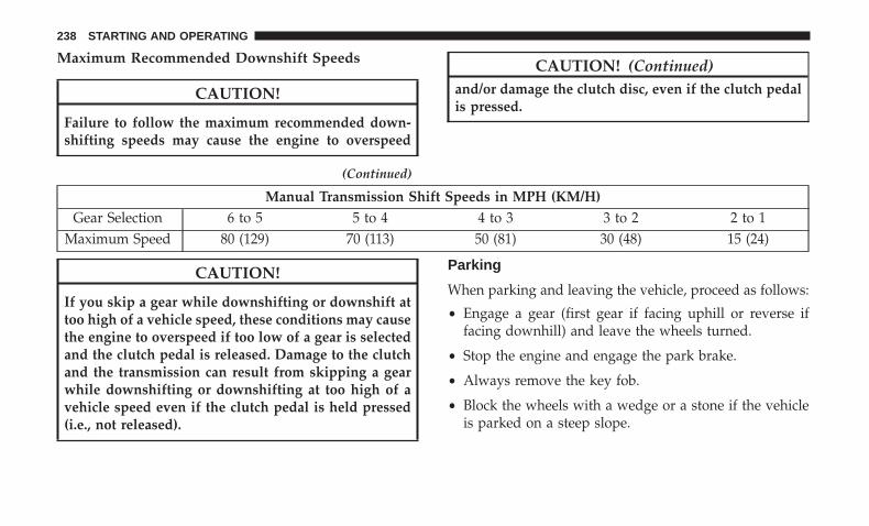
Maximum Recommended Downshift Speeds
CAUTION!
Failure to follow the maximum recommended down-shifting speeds may cause the engine to overspeed
(Continued)
CAUTION! (Continued)and/or damage the clutch disc, even if the clutch pedalis pressed.
Manual Transmission Shift Speeds in MPH (KM/H)Gear Selection 6 to 5 5 to 4 4 to 3 3 to 2 2 to 1
Maximum Speed 80 (129) 70 (113) 50 (81) 30 (48) 15 (24)
CAUTION!
If you skip a gear while downshifting or downshift attoo high of a vehicle speed, these conditions may causethe engine to overspeed if too low of a gear is selectedand the clutch pedal is released. Damage to the clutchand the transmission can result from skipping a gearwhile downshifting or downshifting at too high of avehicle speed even if the clutch pedal is held pressed(i.e., not released).
Parking
When parking and leaving the vehicle, proceed as follows:
• Engage a gear (first gear if facing uphill or reverse iffacing downhill) and leave the wheels turned.
• Stop the engine and engage the park brake.
• Always remove the key fob.
• Block the wheels with a wedge or a stone if the vehicleis parked on a steep slope.
238 STARTING AND OPERATING

NOTE: NEVER leave the car with the gearbox in neutral(or, if equipped with automatic transmission, before plac-ing the gear lever in PARK).
WARNING!
Never leave children unattended in the vehicle. Al-ways remove the key fob when exiting the vehicle andtake it with you.
AUTOMATIC TRANSMISSION — IF EQUIPPED
WARNING!
• Never use the PARK position as a substitute for thepark brake. Always apply the park brake fully whenexiting the vehicle to guard against vehicle move-ment and possible injury or damage.
• Your vehicle could move and injure you and others ifit is not in PARK. Check by WARNING! trying tomove the gear selector out of PARK with the brakepedal released. Make sure the transmission is inPARK before exiting the vehicle.
(Continued)
WARNING! (Continued)• It is dangerous to shift out of PARK or NEUTRAL if
the engine speed is higher than idle speed. If yourfoot is not firmly pressing the brake pedal, thevehicle could accelerate quickly forward or in re-verse. You could lose control of the vehicle and hitsomeone or something. Only shift into gear when theengine is idling normally and your foot is firmlypressing the brake pedal.
• The vehicle may not engage a newly selected gear ifthe vehicle is moving while shifting.
• Unintended movement of a vehicle could injurethose in or near the vehicle. As with all vehicles, youshould never exit a vehicle while the engine isrunning. Before exiting a vehicle, always come to acomplete stop, then apply the park brake, shift thetransmission into PARK, and turn the ignition OFF.When the ignition is in the OFF mode, the transmis-sion is locked in PARK, securing the vehicle againstunwanted movement.
• When leaving the vehicle, always make sure theignition is in the OFF mode, remove the key fob fromthe vehicle, and lock the vehicle.
(Continued)
6
STARTING AND OPERATING 239

WARNING! (Continued)• Never leave children alone in a vehicle, or with
access to an unlocked vehicle. Allowing children tobe in a vehicle unattended is dangerous for a numberof reasons. A child or others could be seriously orfatally injured. Children should be warned not totouch the park brake, brake pedal or the transmis-sion gear selector.
• Do not leave the key fob in or near the vehicle (or ina location accessible to children), and do not leavethe ignition in the ON/RUN mode. A child couldoperate power windows, other controls, or move thevehicle.
CAUTION!
Damage to the transmission may occur if the followingprecautions are not observed:• Shift into or out of PARK or REVERSE only after the
vehicle has come to a complete stop.• Do not shift between PARK, REVERSE, NEUTRAL,
or DRIVE when the engine is above idle speed.• Before shifting into any gear, make sure your foot is
firmly pressing the brake pedal.
NOTE: You must press and hold the brake pedal whileshifting out of PARK.
Ignition Park Interlock
This vehicle is equipped with an Ignition Park Interlockwhich requires the transmission to be in PARK before theignition can be turned to the OFF mode. This helps thedriver avoid inadvertently leaving the vehicle withoutplacing the transmission in PARK. This system also locksthe transmission in PARK whenever the ignition is in theOFF mode.
Brake/Transmission Shift Interlock System
This vehicle is equipped with a Brake Transmission ShiftInterlock system (BTSI) that holds the transmission gearselector in PARK unless the brakes are applied. To shift thetransmission out of PARK, the ignition must be in theON/RUN mode (whether the engine is running or not),and the brake pedal must be pressed. The brake pedal mustalso be pressed to shift from NEUTRAL into DRIVE orREVERSE when the vehicle is stopped or moving at lowspeeds.
240 STARTING AND OPERATING

Six-Speed Or Nine-Speed Automatic Transmission
NOTE: Your vehicle may be equipped with a six-speed ornine-speed automatic transmission, depending on model.This section describes operation of both the six-speed andnine-speed transmission.
The transmission gear range (PRND) is displayed bothbeside the gear selector and in the instrument cluster. Toselect a gear range, push the lock button on the gearselector and move the selector rearward or forward. Youmust also press the brake pedal to shift the transmissionout of PARK (or NEUTRAL, when the vehicle is stopped ormoving at low speeds). Select the DRIVE range for normaldriving.
NOTE: In the event of a mismatch between the gearselector position and the actual transmission gear (forexample, driver selects REVERSE while driving forward),the position indicator will blink continuously until theselector is returned to the proper position, or the requestedshift can be completed.
The electronically-controlled transmission adapts its shiftschedule based on driver inputs, along with environmentaland road conditions. The transmission electronics are self-calibrating; therefore, the first few shifts on a new vehicle
may be somewhat abrupt. This is a normal condition, andprecision shifts will develop within a few hundred miles(kilometers).
The nine-speed transmission has been developed to meetthe needs of current and future FWD/AWD vehicles.Software and calibration is refined to optimize the custom-er’s driving experience and fuel economy. By design, somevehicle and driveline combinations utilize 9th gear only invery specific driving situations and conditions.
Only shift from DRIVE to PARK or REVERSE when theaccelerator pedal is released and the vehicle is stopped. Besure to keep your foot on the brake pedal when shiftingbetween these gears.
The transmission gear selector provides PARK, REVERSE,NEUTRAL, DRIVE, and AutoStick (+/-) shift positions.Manual shifts can be made using the AutoStick shiftcontrol. Moving the gear selector into the AutoStick (+/-)position (beside the DRIVE position) activates AutoStickmode, providing manual shift control and displaying thecurrent gear in the instrument cluster (as 1, 2, 3, etc.).Toggling the gear selector forward (-) or rearward (+) whilein the AutoStick position will manually select the transmis-sion gear. Refer to �AutoStick� in this section for furtherinformation.
6
STARTING AND OPERATING 241

NOTE: If the gear selector cannot be moved to the PARK,REVERSE, or NEUTRAL position (when pushed forward)it is probably in the AutoStick (+/-) position (beside theDRIVE position). In AutoStick mode, the transmission gear(1, 2, 3, etc.) is displayed in the instrument cluster. Movethe gear selector to the right (into the DRIVE [D] position)for access to PARK, REVERSE, and NEUTRAL.
Gear Ranges
Do not depress the accelerator pedal when shifting fromPARK or NEUTRAL into another gear range.
NOTE: After selecting any gear range, wait a moment toallow the selected gear to engage before accelerating. Thisis especially important when the engine is cold.
PARK (P)
This range supplements the parking brake by locking thetransmission. The engine can be started in this range.Never attempt to use PARK while the vehicle is in motion.Apply the parking brake when exiting the vehicle in thisrange.
When parking on a level surface, you may shift thetransmission into PARK first, and then apply the parkingbrake.
When parking on a hill, apply the parking brake beforeshifting the transmission to PARK, otherwise the load onthe transmission locking mechanism may make it difficultto move the gear selector out of PARK. As an addedprecaution, turn the front wheels toward the curb on adownhill grade and away from the curb on an uphill grade.
When exiting the vehicle, always:
1. Apply the parking brake.
2. Shift the transmission into PARK.
3. Turn the ignition OFF.
Gear Selector
242 STARTING AND OPERATING

4. Remove the key fob from the vehicle.
NOTE: Block the wheels with a wedge or a stone if thevehicle is parked on a steep slope.
WARNING!
• Never use the PARK position as a substitute for thepark brake. Always apply the park brake fully whenexiting the vehicle to guard against vehicle move-ment and possible injury or damage.
• Your vehicle could move and injure you and others ifit is not in PARK. Check by WARNING! trying tomove the gear selector out of PARK with the brakepedal released. Make sure the transmission is inPARK before exiting the vehicle.
• It is dangerous to shift out of PARK or NEUTRAL ifthe engine speed is higher than idle speed. If yourfoot is not firmly pressing the brake pedal, thevehicle could accelerate quickly forward or in re-verse. You could lose control of the vehicle and hitsomeone or something. Only shift into gear when theengine is idling normally and your foot is firmlypressing the brake pedal.
(Continued)
WARNING! (Continued)• The vehicle may not engage a newly selected gear if
the vehicle is moving while shifting.• Unintended movement of a vehicle could injure
those in or near the vehicle. As with all vehicles, youshould never exit a vehicle while the engine isrunning. Before exiting a vehicle, always come to acomplete stop, then apply the park brake, shift thetransmission into PARK, and turn the ignition OFF.When the ignition is in the OFF mode, the transmis-sion is locked in PARK, securing the vehicle againstunwanted movement.
• When leaving the vehicle, always make sure theignition is in the OFF mode, remove the key fob fromthe vehicle, and lock the vehicle.
• Never leave children alone in a vehicle, or withaccess to an unlocked vehicle. Allowing children tobe in a vehicle unattended is dangerous for a numberof reasons. A child or others could be seriously orfatally injured. Children should be warned not totouch the park brake, brake pedal or the transmis-sion gear selector.
(Continued)
6
STARTING AND OPERATING 243

WARNING! (Continued)• Do not leave the key fob in or near the vehicle (or in
a location accessible to children), and do not leavethe ignition in the ON/RUN mode. A child couldoperate power windows, other controls, or move thevehicle.
CAUTION!
• Before moving the transmission gear selector out ofPARK, you must turn the ignition to the ON/RUNmode, and also press the brake pedal. Otherwise,damage to the gear selector could result.
• DO NOT race the engine when shifting from PARKor NEUTRAL into another gear range, as this candamage the drivetrain.
The following indicators should be used to ensure that youhave properly engaged the transmission into the PARKposition:
• When shifting into PARK, push the lock button on thegear selector, and firmly move the selector all the wayforward until it stops and is fully seated.
• Look at the transmission gear position display andverify that it indicates the PARK position (P).
• With brake pedal released, verify that the gear selectorwill not move out of PARK.
REVERSE (R)
This range is for moving the vehicle backward. Shift intoREVERSE only after the vehicle has come to a completestop.
NEUTRAL (N)
Use this range when the vehicle is standing for prolongedperiods with the engine running. The engine may bestarted in this range. Apply the park brake and shift thetransmission into PARK if you must exit the vehicle.
WARNING!
Do not coast in NEUTRAL and never turn off theignition to coast down a hill. These are unsafe practicesthat limit your response to changing traffic or roadconditions. You might lose control of the vehicle andhave a collision.
244 STARTING AND OPERATING

CAUTION!
Towing the vehicle, coasting, or driving for any otherreason with the transmission in NEUTRAL can causesevere transmission damage.Refer to “Recreational Towing” in “Starting And Op-erating” and “Towing A Disabled Vehicle” in “In CaseOf Emergency” for further information.
DRIVE (D)
This range should be used for most city and highwaydriving. It provides the smoothest upshifts and downshifts,and the best fuel economy. The transmission automaticallyupshifts through all forward gears. The DRIVE positionprovides optimum driving characteristics under all normaloperating conditions.
When frequent transmission shifting occurs (such as whenoperating the vehicle under heavy loading conditions, inhilly terrain, traveling into strong head winds, or whiletowing a heavy trailer), use the AutoStick shift control toselect a lower gear (refer to �AutoStick� in this section forfurther information). Under these conditions, using a lowergear will improve performance and extend transmissionlife by reducing excessive shifting and heat buildup.
If the transmission temperature exceeds normal operatinglimits, the transmission controller may modify the trans-mission shift schedule, reduce engine torque, and/or ex-pand the range of torque converter clutch engagement.This is done to prevent transmission damage due tooverheating.
If the transmission becomes extremely hot, the �Transmis-sion Temperature Warning Light� may illuminate, and thetransmission may operate differently until the transmissioncools down.
During cold temperatures, transmission operation may bemodified depending on engine and/or transmission tem-perature as well as vehicle speed. This feature improveswarm up time of the engine and transmission to achievemaximum efficiency. Engagement of the torque converterclutch (and, for the nine-speed, shifts into 8th or 9th gear),are inhibited until the engine and/or transmission is warm(refer to the “Note” under “Torque Converter Clutch” inthis section). Normal operation will resume once thetemperature(s) have risen to a suitable level.
AutoStick
AutoStick is a driver-interactive transmission feature pro-viding manual shift control, giving you more control of thevehicle. AutoStick allows you to maximize engine braking,
6
STARTING AND OPERATING 245

eliminate undesirable upshifts and downshifts, and im-prove overall vehicle performance. This system can alsoprovide you with more control during passing, city driv-ing, cold slippery conditions, mountain driving, trailertowing, and many other situations.
Operation
When the gear selector is in the AutoStick position (besidethe DRIVE position), it can be moved forward and rear-ward. This allows the driver to manually select the trans-mission gear being used. Moving the gear selector forward(-) triggers a downshift and rearward (+) an upshift. Thecurrent gear is displayed in the instrument cluster.
In AutoStick mode, the transmission will shift up or downwhen the driver moves the gear selector rearward (+) orforward (-), unless an engine lugging or overspeed condi-tion would result. It will remain in the selected gear untilanother upshift or downshift is chosen, except as describedbelow.
• Six-speed transmissions will automatically upshift whennecessary to prevent engine over-speed.
• The transmission will automatically downshift as thevehicle slows (to prevent engine lugging) and willdisplay the current gear.
• The transmission will automatically downshift to firstgear when coming to a stop. After a stop, the drivershould manually upshift (+) the transmission as thevehicle is accelerated.
• You can start out, from a stop, in first or second gear (orthird gear, in six-speed models, or in 4LO range, Snowmode, or Sand mode, where available). Tapping (+) (at astop) will allow starting in second gear. Starting out insecond gear can be helpful in snowy or icy conditions.
• If a requested downshift would cause the engine toover-speed, that shift will not occur.
• The system will ignore attempts to upshift at too low ofa vehicle speed.
• Transmission shifting will be more noticeable whenAutoStick is enabled.
• The system may revert to automatic shift mode if a faultor overheat condition is detected.
246 STARTING AND OPERATING

NOTE: When Selec-Speed or Hill Descent Control is en-abled, AutoStick is not active.
To disengage AutoStick, return the gear selector to theDRIVE position. You can shift in or out of the AutoStickposition at any time without taking your foot off theaccelerator pedal.
WARNING!
Do not downshift for additional engine braking on aslippery surface. The drive wheels could lose their gripand the vehicle could skid, causing a collision orpersonal injury.
Transmission Limp Home Mode
Transmission function is monitored electronically for abnor-mal conditions. If a condition is detected that could result intransmission damage, Transmission Limp Home Mode isactivated. In this mode, the transmission may operate only ina fixed gear, or may remain in NEUTRAL. The MalfunctionIndicator Light (MIL) may be illuminated. Limp Home Modemay allow the vehicle to be driven to an authorized dealerfor service without damaging the transmission.
In the event of a momentary problem, the transmission canbe reset to regain all forward gears by performing thefollowing steps:
1. Stop the vehicle.
2. Shift the transmission into PARK, if possible. If not, shiftthe transmission to NEUTRAL.
3. Push and hold the ignition until the engine turns OFF.
4. Wait approximately 30 seconds.
5. Restart the engine.
6. Shift into the desired gear range. If the problem is nolonger detected, the transmission will return to normaloperation.
NOTE: Even if the transmission can be reset, we recom-mend that you visit your authorized dealer at your earliestpossible convenience. Your authorized dealer has diagnos-tic equipment to assess the condition of your transmission.If the transmission cannot be reset, authorized dealerservice is required.
6
STARTING AND OPERATING 247
Torque Converter Clutch
A feature designed to improve fuel economy has beenincluded in the automatic transmission on your vehicle. Aclutch within the torque converter engages automaticallyat calibrated speeds. This may result in a slightly differentfeeling or response during normal operation in the uppergears. When the vehicle speed drops or during someaccelerations, the clutch automatically disengages.
NOTE: The torque converter clutch will not engage untilthe engine and/or transmission is warm (usually after 1 to3 miles [2 to 5 km] of driving). Because the engine speed ishigher when the torque converter clutch is not engaged, itmay seem as if the transmission is not shifting properlywhen the vehicle is cold. This is normal. The torqueconverter clutch will function normally once the pow-ertrain is sufficiently warm.
FOUR-WHEEL DRIVE OPERATION — IF EQUIPPED
Jeep Active Drive
Your vehicle may be equipped with a Power Transfer Unit(PTU). This system is automatic with no driver inputs oradditional driving skills required. Under normal drivingconditions, the front wheels provide most of the traction. Ifthe front wheels begin to lose traction, power is shiftedautomatically to the rear wheels. The greater the frontwheel traction loss, the greater the power transfer to therear wheels.
Additionally, on dry pavement under heavy throttle input(where one may have no wheel spin), torque will be sent tothe rear in a preemptive effort to improve vehicle launchand performance characteristics.
CAUTION!
All wheels must have the same size and type tires.Unequal tire sizes must not be used. Unequal tire sizemay cause failure of the power transfer unit.
248 STARTING AND OPERATING

Four Wheel Drive (4x4)
The four wheel drive (4WD) is fully automatic in normaldriving mode.
NOTE: It is not possible to carry out the change of modewhen the vehicle exceeds the speed of 75 mph (120 km/h).
Enabling Four Wheel Drive (4x4)
The buttons for the activation of four wheel drive arelocated on the device Selec-Terrain and allow you to selectthe following:
• 4WD LOCK
• 4WD LOW — (Trailhawk models only)
Active Drive Control — If Equipped
The Power Transfer Unit (PTU) is locked to ensure imme-diate availability of torque to the rear drive axles. Thisfeature is selectable in AUTO mode and automatic in theother driving mode. 4WD LOCK can be enabled by thefollowing ways:
• When the 4WD LOCK button is pushed.
• When the Selec-Terrain switch is rotated from AUTO toany other off-road modes.
Selec-Terrain Switch
6
STARTING AND OPERATING 249

Active Drive With Low Control — (Trailhawk modelsonly)
The 4WD LOW mode helps to improve the off-roadperformance in all modes. To enable 4WD LOW, pleasefollow the steps below:
Enabling 4WD LOW
With the vehicle stationary, the ignition in the ON/RUN orwith the engine running, shift the transmission into NEU-TRAL and push the button once 4WD LOW. The instru-ment cluster will display the message �4WD LOW� oncethe shift is complete.
NOTE:
• Both LOCK and LOW LEDs will blink and then becomeactive on the Selec-Terrain switch until the shift iscomplete.
• The instrument cluster display will illuminate the �4WDLOW� icon.
Disabling 4WD LOW
To disable the 4WD LOW mode, the vehicle must bestationary and the transmission shifted into NEUTRAL.Push the 4WD LOW button once.
SELEC-TERRAIN — IF EQUIPPED
Selec-Terrain combines the capabilities of the vehicle con-trol systems, along with driver input, to provide the bestperformance for all terrains.
Selec-Terrain Switch (Trailhawk)
250 STARTING AND OPERATING

Mode Selection Guide
Rotate the Selec-Terrain knob to select the desired mode.
• AUTO: This four-wheel drive operation is a continuousoperation, is fully automatic and can be used on and offroad. This mode balances traction to ensure maneuver-ability and acceleration improvement compared to avehicle with two wheel drive. This mode also reducesfuel consumption, since it allows the disconnect of thedrive shaft where conditions permit.
• SNOW: This mode allows you to have greater stabilityunder conditions of bad weather. For use on and off roadon surfaces with poor traction, such as roads coveredwith snow. When in SNOW mode (depending on certain
Selec-Terrain Switch
Selec-Terrain Switch (Trailhawk)
6
STARTING AND OPERATING 251

operating conditions), the transmission may use secondgear (rather than first gear) during launches, to mini-mize wheel slippage.
• SAND: For off-road driving or use on surfaces with poortraction, such as dry sand. The transmission is set toprovide maximum traction.
• MUD: For off-road driving or use on surfaces with poortraction, such as roads covered by mud or wet grass.
• ROCK (Trailhawk only): This mode is only available in4WD LOW range. The device sets the vehicle to maxi-mize traction and allow the highest steering capacity foroff-road surfaces. This mode gives you the maximumperformance off-road. Use for low speed obstacles suchas large rocks, deep ruts, etc.
NOTE:
• Rock mode is only available on the vehicles equippedwith the Off-Road package.
• Activate the Hill Descent Control for steep downhillcontrol. See “Electronic Brake Control System” in thissection for further information.
POWER STEERING
The electric power steering system will give you goodvehicle response and increased ease of maneuverability intight spaces. The system will vary its assist to provide lightefforts while parking and good feel while driving. If theelectric steering system experiences a fault that reducesassist or prevents the vehicle from providing assist, youwill still have the ability to steer the vehicle manually.
WARNING!
Continued operation with reduced assist could pose asafety risk to yourself and others. Service should beobtained as soon as possible.
If the “SERVICE POWER STEERING� OR�POWER STEERING ASSIST OFF - SERVICESYSTEM” message and a steering wheel icon aredisplayed on the instrument cluster display, it
indicates that the vehicle needs to be taken to the dealer forservice. It is likely the vehicle has lost power steeringassistance. Refer to “Instrument Cluster Display” in “Get-ting To Know Your Instrument Panel” for further informa-tion.
252 STARTING AND OPERATING
If the “POWER STEERING SYSTEM HOT - PERFOR-MANCE MAY BE LIMITED” message and an icon aredisplayed on the instrument cluster display, it indicatesthat extreme steering maneuvers may have occurred,which caused an over temperature condition in the powersteering system. You will lose power steering assistancemomentarily until the over temperature condition no lon-ger exists. Once driving conditions are safe, then pull overand let vehicle idle for a few moments until the light turnsoff. Refer to “Instrument Cluster Display” in “Getting ToKnow Your Instrument Panel” for further information.
NOTE:
• Even if the power steering assistance is no longeroperational, it is still possible to steer the vehicle. Underthese conditions there will be a substantial increase insteering effort, especially at low speeds and duringparking maneuvers.
• If the condition persists, see your authorized dealer forservice.
STOP/START SYSTEM — IF EQUIPPED
The Stop/Start function is developed to reduce fuel con-sumption. The system will stop the engine automaticallyduring a vehicle stop if the required conditions are met.Releasing the brake pedal or pressing the accelerator pedalwill automatically re-start the engine.
This vehicle has been upgraded with a heavy duty starter,enhanced battery, and other upgraded engine parts, tohandle the additional engine starts.
Automatic Mode
The Stop/Start feature is enabled after every normal cus-tomer engine start. At that time, the system will go intoSTOP/START READY and if all other conditions are met,can go into a STOP/START AUTOSTOP ACTIVE “Au-tostop” mode.
To Activate The Autostop Mode, The Following MustOccur:
• The system must be in STOP/START READY state. ASTOP/START READY message will be displayed in theinstrument cluster display within the Stop/Start section.Refer to “Instrument Cluster Display” in “Getting ToKnow Your Instrument Panel” for further information.
6
STARTING AND OPERATING 253

• The vehicle must be completely stopped.
• The gear selector must be in a forward gear and thebrake pedal depressed.
The engine will shut down, the tachometer will move tothe zero position and the Stop/Start telltale will illuminateindicating you are in Autostop. Customer settings will bemaintained upon return to an engine running condition.
Possible Reasons The Engine Does Not Autostop
Prior to engine shut down, the system will check manysafety and comfort conditions to see if they are fulfilled.Detailed information about the operation of the Stop/Startsystem may be viewed in the instrument cluster displayStop/Start Screen. In the following situations the enginewill not stop:
• Driver’s seat belt is not buckled.
• Driver’s door is not closed.
• Battery temperature is too warm or cold.
• Battery charge is low.
• The vehicle is on a steep grade.
• Cabin heating or cooling is in process and an acceptablecabin temperature has not been achieved.
• HVAC is set to full defrost mode at a high blower speed.
• HVAC set to MAX A/C.
• Engine has not reached normal operating temperature.
• The transmission is not in a forward gear.
• Hood is open.
• Vehicle is in 4WD LOW transfer case mode.
• Brake pedal is not pressed with sufficient pressure.
Other Factors Which Can Inhibit Autostop Include:
• Accelerator pedal input.
• Engine temp too high.
• 5 MPH (8 km/h) threshold not achieved from previousAUTOSTOP.
• Steering angle beyond threshold.
• Adaptive Cruise Control is on and speed is set.
It may be possible for the vehicle to be driven several timeswithout the STOP/START system going into a STOP/START READY state under more extreme conditions of theitems listed above.
254 STARTING AND OPERATING

To Start The Engine While In Autostop Mode
While in a forward gear, the engine will start when thebrake pedal is released or the throttle pedal is depressed.The transmission will automatically re-engage upon en-gine restart.
Conditions That Will Cause The Engine To Start Auto-matically While In Autostop Mode:
• The transmission selector is moved out of DRIVE.
• To maintain cabin temperature comfort.
• HVAC is set to full defrost mode.
• HVAC system temperature or fan speed is manuallyadjusted.
• Battery voltage drops too low.
• Low brake vacuum (e.g. after several brake pedal appli-cations).
• STOP/START OFF switch is pressed.
• A STOP/START system error occurs.
• 4WD system is put into 4WD LOW mode.
Conditions That Force An Application Of The ElectricPark Brake While In Autostop Mode:
• The drivers door is open and brake pedal released.
• The drivers door is open and the drivers seat belt isunbuckled.
• The engine hood has been opened.
• A STOP/START system error occurs.
To Manually Turn Off The Stop/Start System
1. Push the STOP/START Off switch (located on theswitch bank). The light on the switch will illuminate.
STOP/START OFF Switch
6
STARTING AND OPERATING 255
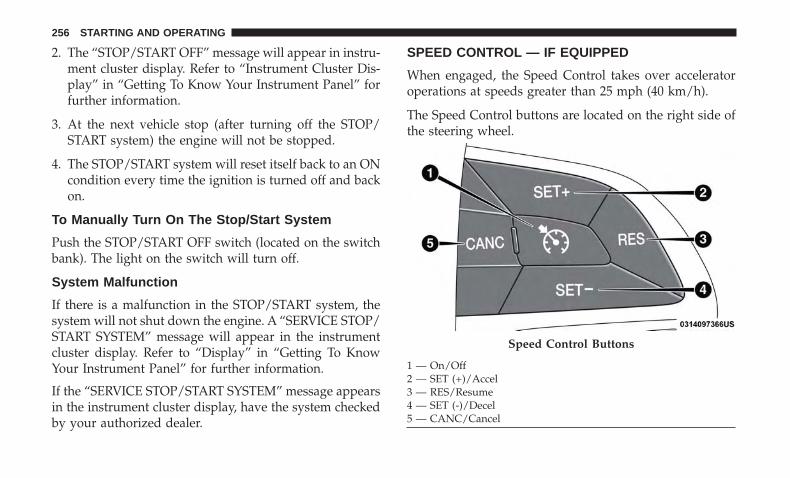
2. The “STOP/START OFF” message will appear in instru-ment cluster display. Refer to “Instrument Cluster Dis-play” in “Getting To Know Your Instrument Panel” forfurther information.
3. At the next vehicle stop (after turning off the STOP/START system) the engine will not be stopped.
4. The STOP/START system will reset itself back to an ONcondition every time the ignition is turned off and backon.
To Manually Turn On The Stop/Start System
Push the STOP/START OFF switch (located on the switchbank). The light on the switch will turn off.
System Malfunction
If there is a malfunction in the STOP/START system, thesystem will not shut down the engine. A “SERVICE STOP/START SYSTEM” message will appear in the instrumentcluster display. Refer to “Display” in “Getting To KnowYour Instrument Panel” for further information.
If the “SERVICE STOP/START SYSTEM” message appearsin the instrument cluster display, have the system checkedby your authorized dealer.
SPEED CONTROL — IF EQUIPPED
When engaged, the Speed Control takes over acceleratoroperations at speeds greater than 25 mph (40 km/h).
The Speed Control buttons are located on the right side ofthe steering wheel.
Speed Control Buttons
1 — On/Off2 — SET (+)/Accel3 — RES/Resume4 — SET (-)/Decel5 — CANC/Cancel
256 STARTING AND OPERATING

NOTE: In order to ensure proper operation, the SpeedControl System has been designed to shut down if multiplespeed control functions are operated at the same time. Ifthis occurs, the Speed Control System can be reactivated bypushing the Speed Control on/off button and resetting thedesired vehicle set speed.
WARNING!
Speed Control can be dangerous where the systemcannot maintain a constant speed. Your vehicle couldgo too fast for the conditions, and you could losecontrol and have an accident. Do not use Speed Controlin heavy traffic or on roads that are winding, icy,snow-covered or slippery.
To Activate
Push the on/off button to activate the Speed Control. Thecruise indicator light in the instrument cluster display willilluminate. To turn the system off, push the on/off buttona second time. The cruise indicator light will turn off. Thesystem should be turned off when not in use.
WARNING!
Leaving the Speed Control system on when not in useis dangerous. You could accidentally set the system orcause it to go faster than you want. You could losecontrol and have an accident. Always leave the systemoff when you are not using it.
To Set A Desired Speed
Turn the Speed Control on.
NOTE: The vehicle should be traveling at a steady speedand on level ground before pushing the SET (+) or SET (-)button.
When the vehicle has reached the desired speed, push theSET (+) or SET (-) button and release. Release the accelera-tor and the vehicle will operate at the selected speed.
To Vary The Speed Setting
To Increase Speed
When the Speed Control is set, you can increase speed bypushing the SET (+) button.
The driver’s preferred units can be selected through theinstrument panel settings. Refer to ”Instrument Cluster
6
STARTING AND OPERATING 257

Display” in “Getting To Know Your Instrument Panel” formore information. The speed increment shown is depen-dent on the chosen speed unit of U.S. (mph) or Metric(km/h):
U.S. Speed (mph)
• Pushing the SET (+) button once will result in a 1 mphincrease in set speed. Each subsequent tap of the buttonresults in an increase of 1 mph.
• If the button is continually pushed, the set speed willcontinue to increase until the button is released, then thenew set speed will be established.
Metric Speed (km/h)
• Pushing the SET (+) button once will result in a 1 km/hincrease in set speed. Each subsequent tap of the buttonresults in an increase of 1 km/h.
• If the button is continually pushed, the set speed willcontinue to increase until the button is released, then thenew set speed will be established.
To Decrease Speed
When the Speed Control is set, you can decrease speed bypushing the SET (-) button.
The driver’s preferred units can be selected through theinstrument panel settings. Refer to ”Instrument ClusterDisplay” in “Getting To Know Your Instrument Panel” formore information. The speed increment shown is depen-dent on the chosen speed unit of U.S. (mph) or Metric(km/h):
U.S. Speed (mph)
• Pushing the SET (-) button once will result in a 1 mphdecrease in set speed. Each subsequent tap of the buttonresults in a decrease of 1 mph.
• If the button is continually pushed, the set speed willcontinue to decrease until the button is released, then thenew set speed will be established.
Metric Speed (km/h)
• Pushing the SET (-) button once will result in a 1 km/hdecrease in set speed. Each subsequent tap of the buttonresults in a decrease of 1 km/h.
• If the button is continually pushed, the set speed willcontinue to decrease until the button is released, then thenew set speed will be established.
258 STARTING AND OPERATING

To Accelerate For Passing
Press the accelerator as you would normally. When thepedal is released, the vehicle will return to the set speed.
To Resume Speed
To resume a previously set speed, push the RES button andrelease. Resume can be used at any speed above 20 mph(32 km/h).
To Deactivate
A soft tap on the brake pedal, pushing the CANC (cancel)button, or normal brake pressure while slowing the vehiclewill deactivate the speed control without erasing the setspeed from memory.
Pushing the on/off button or cycling the ignition to OFF,erases the set speed from memory.
PARKSENSE REAR PARK ASSIST — IF EQUIPPED
The ParkSense Rear Park Assist system provides visual andaudible indications of the distance between the rear fasciaand a detected obstacle when backing up, e.g. during aparking maneuver. Refer to “ParkSense System UsagePrecautions” for limitations of this system and recommen-dations.
ParkSense will retain the last system state (enabled ordisabled) from the last ignition cycle when the ignition ischanged to the ON/RUN position.
ParkSense can be active only when the gear selector is inREVERSE. The system will remain active while in RE-VERSE until the vehicle speed is increased to approxi-mately 7 mph (11 km/h) or above. While in REVERSE, andabove the system’s operating speed, a warning will appearwithin the instrument cluster display indicating the vehiclespeed is too fast. The system will become active againwhen the vehicle speed is decreased to speeds less thanapproximately 6 mph (9 km/h).
ParkSense Sensors
The four ParkSense sensors, located in the rear fascia/bumper, monitor the area behind the vehicle that is withinthe sensors’ field of view. The sensors can detect obstaclesfrom approximately 12 inches (30 cm) up to 79 inches(200 cm) from the rear fascia/bumper in the horizontaldirection, depending on the location, type and orientationof the obstacle.
6
STARTING AND OPERATING 259

ParkSense Warning Display
The ParkSense Warning screen will only be displayed if“Sound and Display” is selected from the Customer -Programmable Features section of the Uconnect System.Refer to �Uconnect Settings” in “Multimedia” for furtherinformation.
The ParkSense Warning screen is located within the instru-ment cluster display. It provides visual warnings to indi-cate the distance between the rear fascia/bumper and thedetected obstacle. Refer to “Instrument Cluster Display” in“Getting To Know Your Instrument Panel” for furtherinformation.
ParkSense Display
When the vehicle is in REVERSE, the instrument clusterdisplay will show the park assist ready system status.
The system will indicate a detected obstacle by showing asingle arc in one or more regions based on the obstacle’sdistance and location relative to the vehicle.
If an obstacle is detected in the center rear region, thedisplay will show a single solid arc in the center rear regionAs the vehicle moves closer to the obstacle, the display will
show the single arc moving closer to the vehicle and theaudible chime increases as the objects gets close to thevehicle.
If an obstacle is detected in the left and /or right rearregion, the display will show a single flashing arc in the leftand/or right rear region As the vehicle moves closer to theobstacle, the display will show the single arc moving closerto the vehicle and the audible chime increases as the objectsgets close to the vehicle.
Single 1/2 Second Tone/Solid Arc
260 STARTING AND OPERATING

Slow Tone/Solid Arc Slow Tone/Solid Arc
6
STARTING AND OPERATING 261

The vehicle is close to the obstacle when the warningdisplay shows one flashing arc and sounds a continuoustone. The following chart shows the warning alert opera-tion when the system is detecting an obstacle:
Fast Tone/Flashing Arc Continuous Tone/Flashing Arc
262 STARTING AND OPERATING

WARNING ALERTSRear
Distance(inches/cm)
Greaterthan
79 inches(200 cm)
79-59 inches(200-
150 cm)
59-47 inches(150-
120 cm)
47-39 inches(120-
100 cm)
39-25 inches(100-65 cm)
25-12 inches(65-30 cm)
Less than12 inches(30 cm)
Arcs — Left None None None None None 2ndFlashing
1st Flashing
Arcs —Center
None 6th Solid 5th Solid 4th Solid 3rdFlashing
2ndFlashing
1st Flashing
Arcs —Right
None None None None None 2ndFlashing
1st Flashing
AudibleAlert
Chime
None Audible chime increases as the objects get close to the vehicle. Continuous
RadioVolumeReduced
No Yes Yes Yes Yes Yes Yes
NOTE: ParkSense will reduce the volume of the radio, ifon, when the system is sounding an audio tone.
6
STARTING AND OPERATING 263

Enabling And Disabling ParkSense
ParkSense can be enabled and disabled with the ParkSenseswitch, located on the switch panel below the Uconnectdisplay.
When the ParkSense switch is pushed to disablethe system, the instrument cluster display willshow the “PARKSENSE OFF” message for ap-proximately five seconds. Refer to “Instrument
Cluster Display” in “Getting To Know Your InstrumentPanel” for further information. When the gear selector ismoved to REVERSE and the system is disabled, the instru-ment cluster display will show the “PARKSENSE OFF”message for as long as the vehicle is in REVERSE.
The ParkSense switch LED will be on when ParkSense isdisabled or requires service. The ParkSense switch LEDwill be off when the system is enabled. If the ParkSenseswitch is pushed, and requires service, the ParkSenseswitch LED will blink momentarily, and then the LED willbe on.
Service The ParkSense Rear Park Assist System
During vehicle start up, when the ParkSense Rear ParkAssist System has detected a faulted condition, the instru-ment cluster display will actuate a single chime, once per
ignition cycle, and it will display the “PARKSENSE UN-AVAILABLE WIPE REAR SENSORS” or the “PARKSENSEUNAVAILABLE SERVICE REQUIRED” message. Refer to“Instrument Cluster Display” for more information. Underthis condition, ParkSense will not operate.
If “PARKSENSE UNAVAILABLE WIPE REAR SENSORS”appears in the instrument cluster display make sure theouter surface and the underside of the rear fascia/bumperis clean and clear of snow, ice, mud, dirt or other obstruc-tion and then cycle the ignition. If the message continues toappear, see your authorized dealer.
If “PARKSENSE UNAVAILABLE SERVICE REQUIRED”appears in the instrument cluster display, see your autho-rized dealer.
Cleaning The ParkSense System
Clean the Rear Park Assist sensors with water, car washsoap and a soft cloth. Do not use rough or hard cloths. Inwashing stations, clean sensors quickly keeping the vaporjet/high pressure washing nozzles at least 4 inches (10 cm)from the sensors. Do not scratch or poke the sensors.Otherwise, you could damage the sensors.
264 STARTING AND OPERATING

ParkSense System Usage Precautions
NOTE:
• Ensure that the rear bumper is free of snow, ice, mud,dirt and debris to keep the ParkSense system operatingproperly.
• Jackhammers, large trucks, and other vibrations couldaffect the performance of ParkSense.
• When you turn ParkSense OFF, the instrument clusterdisplay will read “PARKSENSE OFF” Furthermore, onceyou turn ParkSense OFF, it remains off until you turn iton again, even if you cycle the ignition.
• ParkSense, when on, will reduce the volume of the radiowhen it is sounding a tone.
• Clean the ParkSense sensors regularly, taking care not toscratch or damage them. The sensors must not becovered with ice, snow, slush, mud, dirt or debris.Failure to do so can result in the system not workingproperly. The ParkSense system might not detect anobstacle behind the fascia/bumper, or it could provide afalse indication that an obstacle is behind the fascia/bumper.
• Use the ParkSense switch to turn the ParkSense systemOFF if objects such as bicycle carriers, trailer hitches, etc.
are placed within 12 inches (30 cm) from the rearfascia/bumper. Failure to do so can result in the systemmisinterpreting a close object as a sensor problem,causing the “PARKSENSE UNAVAILABLE SERVICEREQUIRED” message to be displayed in the instrumentcluster display.
• The operation of the rear sensors is automatically deac-tivated when the trailer’s electric plug is inserted in thevehicle’s tow hook socket. The rear sensors are automati-cally reactivated when the trailer’s cable plug is re-moved.
WARNING!
• Drivers must be careful when backing up even whenusing ParkSense. Always check carefully behindyour vehicle, look behind you, and be sure to checkfor pedestrians, animals, other vehicles, obstructions,and blind spots before backing up. You are respon-sible for safety and must continue to pay attention toyour surroundings. Failure to do so can result inserious injury or death.
• Before using ParkSense, it is strongly recommendedthat the ball mount and hitch ball assembly is
(Continued)
6
STARTING AND OPERATING 265

WARNING! (Continued)disconnected from the vehicle when the vehicle isnot used for towing. Failure to do so can result ininjury or damage to vehicles or obstacles because thehitch ball will be much closer to the obstacle than therear fascia when the loudspeaker sounds the con-tinuous tone. Also, the sensors could detect the ballmount and hitch ball assembly, depending on its sizeand shape, giving a false indication that an obstacleis behind the vehicle.
CAUTION!
• ParkSense is only a parking aid and it is unable torecognize every obstacle, including small obstacles.Parking curbs might be temporarily detected or notdetected at all. Obstacles located above or below thesensors will not be detected when they are in closeproximity.
• The vehicle must be driven slowly when usingParkSense in order to be able to stop in time when anobstacle is detected. It is recommended that thedriver looks over his/her shoulder when usingParkSense.
LANESENSE — IF EQUIPPED
LaneSense Operation
The LaneSense system is operational at speeds above37 mph (60 km/h) and below 112 mph (180 km/h). TheLaneSense system uses a forward looking camera to detectlane markings and measure vehicle position within thelane boundaries.
When both lane markings are detected and the driverunintentionally drifts out of the lane (no turn signalapplied), the LaneSense system provides a haptic warningin the form of torque applied to the steering wheel, as wellas a visual warning in the instrument cluster display, toprompt the driver to remain within the lane boundaries.
The driver may manually override the haptic warning byapplying torque into the steering wheel at any time.
When only a single lane marking is detected and the driverunintentionally drifts across the lane marking (no turnsignal applied), the LaneSense system provides a visualwarning through the instrument cluster display to promptthe driver to remain within the lane. When only a singlelane marking is detected, a haptic (torque) warning will notbe provided.
266 STARTING AND OPERATING

NOTE: When operating conditions have been met, theLaneSense system will monitor if the driver’s hands are onthe steering wheel and provide an audible and visualwarning to the driver when the driver’s hands are notdetected on the steering wheel. The system will cancel ifthe driver does not return their hands to the wheel.
Turning LaneSense On Or Off
The default status of LaneSense is “Off”.
The LaneSense button is located on the switch panel belowthe Uconnect display.
To turn the LaneSense system on, push the LaneSensebutton to turn the system on (LED turns off). A “Lane SenseOn” message is shown in the instrument cluster display.
To turn the LaneSense system off, push the LaneSensebutton once to turn the system off (LED turns on).
NOTE: The LaneSense system will retain the last systemstate on or off from the last ignition cycle when the ignitionis changed to the ON/RUN position.
LaneSense Warning Message
The LaneSense system will indicate the current lane driftcondition through the instrument cluster display.
LaneSense Warning Button
Lane Sense On Message
6
STARTING AND OPERATING 267

Base Instrument Cluster Display — If Equipped
When the LaneSense system is on; the lane lines are graywhen both of the lane boundaries have not been detectedand the LaneSense telltale is solid white.
Left Lane Departure — Only Left Lane Detected
• When the LaneSense system is on, the LaneSense telltaleis solid white when only the left lane marking has
been detected and the system is ready to providevisual warnings in the instrument cluster display if anunintentional lane departure occurs.
• When the LaneSense system senses the lane has beenapproached and is in a lane departure situation, the leftthick lane line flashes from white to gray, the left thinline remains solid white and the LaneSense telltale
changes from solid white to flashing yellow.
NOTE: The LaneSense system operates with the similarbehavior for a right lane departure when only the rightlane marking has been detected.
System On (Gray Lines/White Telltale )Lane Approached (Flashing White To Gray Thick
Line/Flashing Yellow Telltale )
268 STARTING AND OPERATING

Left Lane Departure — Both Lanes Detected
• When the LaneSense system is on, the lane lines turnfrom gray to white to indicate that both of the lanemarkings have been detected. The LaneSense telltale
is solid green when both lane markings have beendetected and the system is “armed” to provide visualwarnings in the instrument cluster display and atorque warning in the steering wheel if an uninten-tional lane departure occurs.
• When the LaneSense system senses a lane drift situation,the left thick lane line and the left thin line turn solid
white. The LaneSense telltale changes from solidgreen to solid yellow. At this time torque is applied tothe steering wheel in the opposite direction of thelane boundary.
• For example: if approaching the left side of the lane thesteering wheel will turn to the right.
• When the LaneSense system senses the lane has beenapproached and is in a lane departure situation, the leftthick lane line flashes from white to gray, the left thinline remains solid white and the LaneSense telltale
changes from solid yellow to flashing yellow. At
Lanes Sensed (White Lines/Green Telltale )
Lane Sensed (Solid White Thick Line, Solid White ThinLine/Solid Yellow Telltale )
6
STARTING AND OPERATING 269

this time torque is applied to the steering wheel in theopposite direction of the lane boundary.
• For example: if approaching the left side of the lane thesteering wheel will turn to the right.
NOTE: The LaneSense system operates with the similarbehavior for a right lane departure.
Premium Instrument Cluster Display — If Equipped
When the LaneSense system is on; the lane lines are graywhen both of the lane boundaries have not been detectedand the LaneSense telltale is solid white.
Left Lane Departure — Only Left Lane Detected
• When the LaneSense system is on, the LaneSense telltaleis solid white when only the left lane marking has
been detected and the system is ready to providevisual warnings in the instrument cluster display if anunintentional lane departure occurs.
• When the LaneSense system senses the lane has beenapproached and is in a lane departure situation, the leftthick lane line flashes yellow, the left thin line remainssolid yellow and the LaneSense telltale changes fromsolid white to flashing yellow.
Lane Approached (Flashing White To Gray Thick Line,Solid White Thin Line/Flashing Yellow Telltale )
System On (Gray Lines/White Telltale )
270 STARTING AND OPERATING

NOTE: The LaneSense system operates with the similarbehavior for a right lane departure when only the rightlane marking has been detected.
Left Lane Departure — Both Lanes Detected
• When the LaneSense system is on, the lane lines turnfrom gray to white to indicate that both of the lanemarkings have been detected. The LaneSense telltale
is solid green when both lane markings have beendetected and the system is “armed” to provide visual
warnings in the instrument cluster display and atorque warning in the steering wheel if an uninten-tional lane departure occurs.
• When the LaneSense system senses a lane drift situation,the left thick lane line and left thin line turn solid yellow.The LaneSense telltale changes from solid green tosolid yellow. At this time torque is applied to thesteering wheel in the opposite direction of the laneboundary.
• For example: if approaching the left side of the lane thesteering wheel will turn to the right.
Lane Approached (Flashing Yellow Thick Line, SolidYellow Thin Line/Flashing Yellow Telltale )
Lanes Sensed (White Lines/Green Telltale )
6
STARTING AND OPERATING 271

• When the LaneSense system senses the lane has beenapproached and is in a lane departure situation, the leftthick lane line flashes yellow and the left thin lineremains solid yellow. The LaneSense telltale changesfrom solid yellow to flashing yellow. At this timetorque is applied to the steering wheel in the oppositedirection of the lane boundary.
• For example: if approaching the left side of the lane thesteering wheel will turn to the right.
NOTE: The LaneSense system operates with the similarbehavior for a right lane departure.
Changing LaneSense Status
The LaneSense system has settings to adjust the intensity ofthe torque warning (Low/Medium/High) and the warn-ing zone sensitivity (Early/Medium/Late) that you canconfigure through the Uconnect system screen. Refer to“Uconnect Settings” in “Multimedia” for further informa-tion.
Lane Sensed (Solid Yellow Thick Line, Solid Yellow ThinLine/Solid Yellow Telltale )
Lane Approached (Flashing Yellow Thick Line, SolidYellow Thin Line/Flashing Yellow Telltale )
272 STARTING AND OPERATING
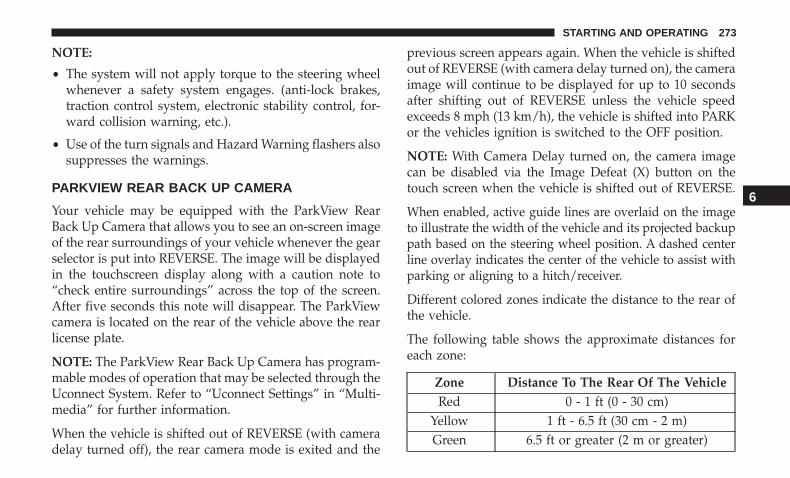
NOTE:
• The system will not apply torque to the steering wheelwhenever a safety system engages. (anti-lock brakes,traction control system, electronic stability control, for-ward collision warning, etc.).
• Use of the turn signals and Hazard Warning flashers alsosuppresses the warnings.
PARKVIEW REAR BACK UP CAMERA
Your vehicle may be equipped with the ParkView RearBack Up Camera that allows you to see an on-screen imageof the rear surroundings of your vehicle whenever the gearselector is put into REVERSE. The image will be displayedin the touchscreen display along with a caution note to“check entire surroundings” across the top of the screen.After five seconds this note will disappear. The ParkViewcamera is located on the rear of the vehicle above the rearlicense plate.
NOTE: The ParkView Rear Back Up Camera has program-mable modes of operation that may be selected through theUconnect System. Refer to “Uconnect Settings” in “Multi-media” for further information.
When the vehicle is shifted out of REVERSE (with cameradelay turned off), the rear camera mode is exited and the
previous screen appears again. When the vehicle is shiftedout of REVERSE (with camera delay turned on), the cameraimage will continue to be displayed for up to 10 secondsafter shifting out of REVERSE unless the vehicle speedexceeds 8 mph (13 km/h), the vehicle is shifted into PARKor the vehicles ignition is switched to the OFF position.
NOTE: With Camera Delay turned on, the camera imagecan be disabled via the Image Defeat (X) button on thetouch screen when the vehicle is shifted out of REVERSE.
When enabled, active guide lines are overlaid on the imageto illustrate the width of the vehicle and its projected backuppath based on the steering wheel position. A dashed centerline overlay indicates the center of the vehicle to assist withparking or aligning to a hitch/receiver.
Different colored zones indicate the distance to the rear ofthe vehicle.
The following table shows the approximate distances foreach zone:
Zone Distance To The Rear Of The VehicleRed 0 - 1 ft (0 - 30 cm)
Yellow 1 ft - 6.5 ft (30 cm - 2 m)Green 6.5 ft or greater (2 m or greater)
6
STARTING AND OPERATING 273

WARNING!
Drivers must be careful when backing up even whenusing the ParkView Rear Back Up Camera. Alwayscheck carefully behind your vehicle, and be sure tocheck for pedestrians, animals, other vehicles, obstruc-tions, or blind spots before backing up. You are re-sponsible for the safety of your surroundings and mustcontinue to pay attention while backing up. Failure todo so can result in serious injury or death.
CAUTION!
• To avoid vehicle damage, ParkView should only beused as a parking aid. The ParkView camera isunable to view every obstacle or object in your drivepath.
• To avoid vehicle damage, the vehicle must be drivenslowly when using ParkView to be able to stop intime when an obstacle is seen. It is recommendedthat the driver look frequently over his/her shoulderwhen using ParkView.
NOTE: If snow, ice, mud, or any foreign substance buildsup on the camera lens, clean the lens, rinse with water, anddry with a soft cloth. Do not cover the lens.
REFUELING THE VEHICLE
The Capless Fuel System uses a flapper placed at the fillerpipe of the fuel tank; it opens and closes automaticallyupon insertion/extraction of the fuel nozzle. The CaplessFuel System is designed so that it prevents the filling of anincorrect type of fuel.
1. Open the fuel filler door by pushing on the outer edge ofthe Fuel Door.
Fuel Filler Door
274 STARTING AND OPERATING

2. There is no fuel filler cap. A flapper door inside the pipeseals the system.
3. Insert the fuel nozzle fully into the filler pipe; the nozzleopens and holds the flapper door while refueling.
4. Fill the vehicle with fuel, and when the fuel nozzle“clicks” or shuts off, the fuel tank is full.
5. Wait ten seconds before removing the fuel nozzle toallow fuel to drain from nozzle.
6. Remove the fuel nozzle and close the fuel door.
Emergency Gas Can Refueling
Most gas cans will not open the flapper door. A funnel isprovided to open the flapper door to allow emergencyrefueling with a gas can.
1. Retrieve funnel from the spare tire storage area.
2. Insert funnel into same filler pipe opening as the fuelnozzle.
3. Ensure funnel is inserted fully to hold flapper dooropen.
4. Pour fuel into funnel opening.
Filling Procedure
Fuel Funnel
6
STARTING AND OPERATING 275

5. Remove funnel from filler pipe, clean off prior to puttingback in the spare tire storage area.
NOTE:
• When the fuel nozzle “clicks” or shuts off, the fuel tankis full.
WARNING!
• Never have any smoking materials lit in or near thevehicle when the gas cap is removed or the tank isbeing filled.
• Never add fuel when the engine is running. This isin violation of most state and federal fire regulationsand may cause the MIL to turn on.
• A fire may result if gasoline is pumped into aportable container that is inside of a vehicle. Youcould be burned. Always place gas containers on theground while filling.
VEHICLE LOADING
Certification Label
As required by National Highway Traffic Safety Adminis-tration regulations, your vehicle has a certification labelaffixed to the driver’s side door or pillar.
This label contains the month and year of manufacture,Gross Vehicle Weight Rating (GVWR), Gross Axle WeightRating (GAWR) front and rear, and Vehicle IdentificationNumber (VIN). A Month-Day-Hour (MDH) number isincluded on this label and indicates the Month, Day andHour of manufacture. The bar code that appears on thebottom of the label is your VIN.
Gross Vehicle Weight Rating (GVWR)
The GVWR is the total permissible weight of your vehicleincluding driver, passengers, vehicle, options and cargo.The label also specifies maximum capacities of front andrear axle systems (GAWR). Total load must be limited soGVWR and front and rear GAWR are not exceeded.
Payload
The payload of a vehicle is defined as the allowable loadweight a truck can carry, including the weight of the driver,all passengers, options and cargo.
Gross Axle Weight Rating (GAWR)
The GAWR is the maximum permissible load on the frontand rear axles. The load must be distributed in the cargoarea so that the GAWR of each axle is not exceeded.
276 STARTING AND OPERATING

Each axle GAWR is determined by the components in thesystem with the lowest load carrying capacity (axle,springs, tires or wheels). Heavier axles or suspensioncomponents sometimes specified by purchasers for in-creased durability does not necessarily increase the vehi-cle’s GVWR.
Tire Size
The tire size on the Vehicle Certification Label representsthe actual tire size on your vehicle. Replacement tires mustbe equal to the load capacity of this tire size.
Rim Size
This is the rim size that is appropriate for the tire sizelisted.
Inflation Pressure
This is the cold tire inflation pressure for your vehicle forall loading conditions up to full GAWR.
Curb Weight
The curb weight of a vehicle is defined as the total weightof the vehicle with all fluids, including vehicle fuel, at fullcapacity conditions, and with no occupants or cargo loadedinto the vehicle. The front and rear curb weight values are
determined by weighing your vehicle on a commercialscale before any occupants or cargo are added.
Loading
The actual total weight and the weight of the front and rearof your vehicle at the ground can best be determined byweighing it when it is loaded and ready for operation.
The entire vehicle should first be weighed on a commercialscale to insure that the GVWR has not been exceeded. Theweight on the front and rear of the vehicle should then bedetermined separately to be sure that the load is properlydistributed over the front and rear axle. Weighing thevehicle may show that the GAWR of either the front or rearaxles has been exceeded but the total load is within thespecified GVWR. If so, weight must be shifted from front torear or rear to front as appropriate until the specifiedweight limitations are met. Store the heavier items downlow and be sure that the weight is distributed equally. Stowall loose items securely before driving.
Improper weight distributions can have an adverse effecton the way your vehicle steers and handles and the waythe brakes operate.
6
STARTING AND OPERATING 277

CAUTION!
Do not load your vehicle any heavier than the GVWR orthe maximum front and rear GAWR. If you do, parts onyour vehicle can break, or it can change the way yourvehicle handles. This could cause you to lose control.Also overloading can shorten the life of your vehicle.
TRAILER TOWING
In this section you will find safety tips and information onlimits to the type of towing you can reasonably do withyour vehicle. Before towing a trailer, carefully review thisinformation to tow your load as efficiently and safely aspossible.
To maintain the New Vehicle Limited Warranty coverage,follow the requirements and recommendations in thismanual concerning vehicles used for trailer towing.
Common Towing Definitions
The following trailer towing related definitions will assistyou in understanding the following information:
Gross Vehicle Weight Rating (GVWR)
The GVWR is the total allowable weight of your vehicle.This includes driver, passengers, cargo and tongue weight.
The total load must be limited so that you do not exceedthe GVWR. Refer to “Vehicle Loading/Vehicle CertificationLabel” in “Starting And Operating” for further informa-tion.
Gross Trailer Weight (GTW)
The GTW is the weight of the trailer plus the weight of allcargo, consumables and equipment (permanent or tempo-rary) loaded in or on the trailer in its �loaded and ready foroperation� condition.
The recommended way to measure GTW is to put yourfully loaded trailer on a vehicle scale. The entire weight ofthe trailer must be supported by the scale.
Gross Axle Weight Rating (GAWR)
The GAWR is the maximum capacity of the front and rearaxles. Distribute the load over the front and rear axlesevenly. Make sure that you do not exceed either front orrear GAWR. Refer to “Vehicle Loading/Vehicle Certifica-tion Label” in “Starting And Operating” for further infor-mation.
278 STARTING AND OPERATING

WARNING!
It is important that you do not exceed the maximumfront or rear GAWR. A dangerous driving conditioncan result if either rating is exceeded. You could losecontrol of the vehicle and have a collision.
Tongue Weight (TW)
The tongue weight is the downward force exerted on thehitch ball by the trailer. You must consider this as part ofthe load on your vehicle.
Trailer Frontal Area
The frontal area is the maximum height multiplied by themaximum width of the front of a trailer.
Trailer Sway Control
The trailer sway control can be a mechanical telescopinglink that can be installed between the hitch receiver and thetrailer tongue that typically provides adjustable frictionassociated with the telescoping motion to dampen anyunwanted trailer swaying motions while traveling.
If equipped, the electronic Trailer Sway Control (TSC)recognizes a swaying trailer and automatically appliesindividual wheel brakes and/or reduces engine power toattempt to eliminate the trailer sway.
Weight-Carrying Hitch
A weight-carrying hitch supports the trailer tongue weight,just as if it were luggage located at a hitch ball or someother connecting point of the vehicle. These kinds ofhitches are the most popular on the market today and theyare commonly used to tow small and medium sizedtrailers.
Weight-Distributing Hitch
A weight-distributing system works by applying leveragethrough spring (load) bars. They are typically used forheavier loads to distribute trailer tongue weight to the towvehicle’s front axle and the trailer axle(s). When used inaccordance with the manufacturer’s directions, it providesfor a more level ride, offering more consistent steering andbrake control thereby enhancing towing safety. The addi-tion of a friction/hydraulic sway control also dampenssway caused by traffic and crosswinds and contributespositively to tow vehicle and trailer stability. Trailer swaycontrol and a weight distributing (load equalizing) hitchare recommended for heavier Tongue Weights (TW) and
6
STARTING AND OPERATING 279

may be required depending on vehicle and trailerconfiguration/loading to comply with Gross Axle WeightRating (GAWR) requirements.
WARNING!
• An improperly adjusted Weight Distributing Hitchsystem may reduce handling, stability, braking per-formance, and could result in a collision.
(Continued)
WARNING! (Continued)• Weight Distributing Systems may not be compatible
with Surge Brake Couplers. Consult with your hitchand trailer manufacturer or a reputable RecreationalVehicle dealer for additional information.
Trailer Towing Weights (Maximum Trailer Weight Ratings)
Engine/Transmission ModelMaximum GTW (Gross
Trailer Wt.)Maximum Tongue Wt. (See
Note)2.4L / Manual FWD or 4WD Trailer towing is not recommended.2.4L / 6 Speed Auto FWD or 4WD Trailer towing is not recommended.2.4L / 9 Speed Auto 4WD 2000 lbs (907 kg) 200 lbs (90 kg)
When towing a trailer the technically permissible laden weight may be exceeded by not more than 10% or 220 lbs(100 kg), whichever is lower provided that the operating speed is restricted to 62 mph (100 km/h) or less.
Refer to local laws for maximum trailer towing speeds and loads.Towing limits quoted represent the maximum towing ability of the vehicle at its Gross Combined Mass to restart on a
12 percent gradient at sea level.The performance and economy of all models will be reduced when used for towing.
280 STARTING AND OPERATING

Trailer And Tongue Weight
Never exceed the maximum tongue weight stamped onyour trailer hitch.
Consider the following items when computing the weighton the front/rear axles of the vehicle:
• The trailer tongue weight of the trailer.
• The weight of any other type of cargo or equipment putin or on your vehicle.
• The weight of the driver and all passengers.
NOTE: Remember that everything put into or on thetrailer adds to the load on your vehicle. Also, additional
factory-installed options, or authorized dealer-installedoptions, must be considered as part of the total load onyour vehicle. Refer to the tire loading information placardlocated on the driver’s door pillar for the maximumcombined weight of occupants and cargo for your vehicle.
Towing Requirements
To promote proper break-in of your new vehicle drivetraincomponents, the following guidelines are recommended.
CAUTION!
• Do not tow a trailer at all during the first 500 miles(805 km) the new vehicle is driven. The engine, axleor other parts could be damaged.
• Then, during the first 500 miles (805 km) that a trailer istowed, do not drive over 50 mph (80 km/h) and do notmake starts at full throttle. This helps the engine andother parts of the vehicle wear in at the heavier loads.
Perform the maintenance listed in the “Scheduled Servic-ing”. Refer to “Scheduled Servicing” in “Servicing AndMaintenance” for the proper maintenance intervals. Whentowing a trailer, never exceed the GAWR or GCWR ratings.
6
STARTING AND OPERATING 281

WARNING!
Improper towing can lead to a collision. Follow theseguidelines to make your trailer towing as safe aspossible:• Make certain that the load is secured in the trailer
and will not shift during travel. When traileringcargo that is not fully secured, dynamic load shiftscan occur that may be difficult for the driver tocontrol. You could lose control of your vehicle andhave a collision.
• When hauling cargo or towing a trailer, do notoverload your vehicle or trailer. Overloading cancause a loss of control, poor performance or damageto brakes, axle, engine, transmission, steering, sus-pension, chassis structure or tires.
• Safety chains must always be used between yourvehicle and trailer. Always connect the chains to thehook retainers of the vehicle hitch. Cross the chainsunder the trailer tongue and allow enough slack forturning corners.
• Vehicles with trailers should not be parked on agrade. When parking, apply the parking brake on thetow vehicle. Put the tow vehicle transmission in
(Continued)
WARNING! (Continued)PARK. For four-wheel drive vehicles, make sure thetransfer case is not in NEUTRAL. Always, block or�chock� the trailer wheels.
• GCWR must not be exceeded.• Total weight must be distributed between the tow
vehicle and the trailer such that the following fourratings are not exceeded:
1. GVWR
2. GTW
3. GAWR
4. Tongue weight rating for the trailer hitch utilized.
Towing Requirements — Tires
• Do not attempt to tow a trailer while using a compactspare tire.
• Do not drive more than 50 mph (80 km/h) when towingwhile using a full size spare tire.
• Proper tire inflation pressures are essential to the safeand satisfactory operation of your vehicle. Refer to“Tires” in “Servicing And Maintenance” for proper tireinflation procedures.
282 STARTING AND OPERATING

• Check the trailer tires for proper tire inflation pressuresbefore trailer usage.
• Check for signs of tire wear or visible tire damage beforetowing a trailer. Refer to “Tires” in “Servicing AndMaintenance” for the proper inspection procedure.
• When replacing tires, refer to “Tires” in “Servicing AndMaintenance” for the proper tire replacement proce-dures. Replacing tires with a higher load carrying capac-ity will not increase the vehicle’s GVWR and GAWRlimits.
Towing Requirements — Trailer Brakes
• Do not interconnect the hydraulic brake system orvacuum system of your vehicle with that of the trailer.This could cause inadequate braking and possible per-sonal injury.
• An electronically actuated trailer brake controller isrequired when towing a trailer with electronically actu-ated brakes. When towing a trailer equipped with ahydraulic surge actuated brake system, an electronicbrake controller is not required.
• Trailer brakes are recommended for trailers over1,000 lbs (453 kg) and required for trailers in excess of2,000 lbs (907 kg).
WARNING!
• Do not connect trailer brakes to your vehicle’s hy-draulic brake lines. It can overload your brake sys-tem and cause it to fail. You might not have brakeswhen you need them and could have a collision.
• Towing any trailer will increase your stopping dis-tance. When towing you should allow for additionalspace between your vehicle and the vehicle in frontof you. Failure to do so could result in a collision.
CAUTION!
If the trailer weighs more than 1,000 lbs (453 kg)loaded, it should have its own brakes and they shouldbe of adequate capacity. Failure to do this could lead toaccelerated brake lining wear, higher brake pedaleffort, and longer stopping distances.
Towing Requirements — Trailer Lights And Wiring
Whenever you pull a trailer, regardless of the trailer size,stoplights and turn signals on the trailer are required formotoring safety.
6
STARTING AND OPERATING 283

The Trailer Tow Package may include a four- and seven-pinwiring harness. Use a factory approved trailer harness andconnector.
NOTE: Do not cut or splice wiring into the vehicle’s wiringharness.
The electrical connections are all complete to the vehiclebut you must mate the harness to a trailer connector. Referto the following illustrations.
NOTE:
• Disconnect trailer wiring connector from the vehiclebefore launching a boat (or any other device pluggedinto vehicle’s electrical connect) into water.
• Be sure to reconnect after clear from water area.
Four-Pin Connector
1 — Female Pins 4 — Park2 — Male Pin 5 — Left Stop/Turn3 — Ground 6 — Right Stop/Turn
284 STARTING AND OPERATING
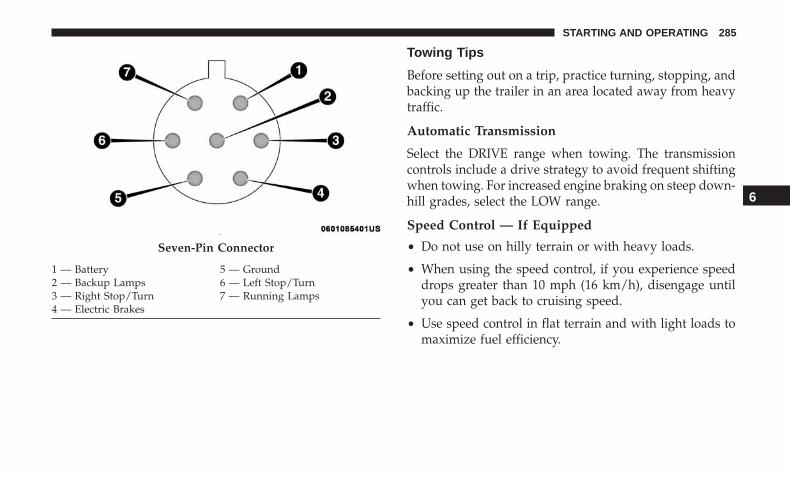
Towing Tips
Before setting out on a trip, practice turning, stopping, andbacking up the trailer in an area located away from heavytraffic.
Automatic Transmission
Select the DRIVE range when towing. The transmissioncontrols include a drive strategy to avoid frequent shiftingwhen towing. For increased engine braking on steep down-hill grades, select the LOW range.
Speed Control — If Equipped
• Do not use on hilly terrain or with heavy loads.
• When using the speed control, if you experience speeddrops greater than 10 mph (16 km/h), disengage untilyou can get back to cruising speed.
• Use speed control in flat terrain and with light loads tomaximize fuel efficiency.
Seven-Pin Connector
1 — Battery 5 — Ground2 — Backup Lamps 6 — Left Stop/Turn3 — Right Stop/Turn 7 — Running Lamps4 — Electric Brakes
6
STARTING AND OPERATING 285

Cooling System
To reduce potential for engine and transmission overheat-ing, take the following actions:
City Driving
• In city traffic — while stopped, place the transmission inNEUTRAL, but do not increase engine idle speed.
Highway Driving
• Reduce speed.
• Temporarily turn off air conditioning.
RECREATIONAL TOWING (BEHIND MOTORHOME, ETC.)Towing This Vehicle Behind Another Vehicle
TOWING CONDITIONWHEELS OFF THE
GROUNDFRONT WHEEL DRIVE
(FWD)FOUR-WHEEL DRIVE
(4WD)Flat Tow NONE NOT ALLOWED NOT ALLOWED
Dolly Tow REAR NOT ALLOWED NOT ALLOWEDFRONT OK NOT ALLOWED
On Trailer ALL BEST METHOD OK
NOTE:
• When towing your vehicle, always follow applicablestate and provincial laws. Contact state and provincialHighway Safety offices for additional details.
• You must ensure that the Auto Park Brake feature isdisabled before towing this vehicle, to avoid inadvertentElectric Park Brake engagement. The Auto Park Brakefeature is enabled or disabled via the customer program-mable features in the Uconnect Settings.
286 STARTING AND OPERATING

Recreational Towing — Front-Wheel Drive (FWD)Models
Recreational towing is allowed ONLY if the front wheelsare OFF the ground. This may be accomplished using a towdolly (front wheels off the ground) or vehicle trailer (allfour wheels off the ground). If using a tow dolly, follow thisprocedure:
1. Properly secure the dolly to the tow vehicle, followingthe dolly manufacturer’s instructions.
2. Drive the front wheels onto the tow dolly.
3. Apply the Electric Park Brake (EPB). Place the transmis-sion in PARK. Turn the engine OFF.
4. Properly secure the front wheels to the dolly, followingthe dolly manufacturer’s instructions.
5. Turn the ignition to the ON/RUN position, but do notstart the engine.
6. Press and hold the brake pedal.
7. Release the Electric Park Brake (EPB).
8. Turn the ignition OFF, remove the key fob, and releasethe brake pedal.
CAUTION!
• Towing with the front wheels on the ground willcause severe transmission damage. Damage fromimproper towing is not covered under the NewVehicle Limited Warranty.
• Ensure that the Electric Park Brake is released, andremains released, while being towed.
Recreational Towing — 4X4 Models
Recreational towing (with all four wheels on the ground, orusing a towing dolly) is NOT ALLOWED. This vehicle maybe towed on flatbed or vehicle trailer provided all fourwheels are OFF the ground.
CAUTION!
Towing this vehicle with ANY of its wheels on theground can cause severe transmission and/or powertransfer unit damage. Damage from improper towingis not covered under the New Vehicle Limited War-ranty.
6
STARTING AND OPERATING 287
DRIVING TIPS
On-Road Driving Tips
Utility vehicles have higher ground clearance and a nar-rower track to make them capable of performing in a widevariety of off-road applications. Specific design character-istics give them a higher center of gravity than conven-tional passenger cars.
An advantage of the higher ground clearance is a betterview of the road, allowing you to anticipate problems.They are not designed for cornering at the same speeds asconventional passenger cars any more than low-slungsports cars are designed to perform satisfactorily in off-road conditions. Avoid sharp turns or abrupt maneuvers.As with other vehicles of this type, failure to operate thisvehicle correctly may result in loss of control or vehiclerollover.
Off-Road Driving Tips
When To Use 4WD LOW Range
When off-road driving, shift to 4WD LOW for additionaltraction and control on slippery or difficult terrain, ascend-ing or descending steep hills, and to increase low-speedpulling power (refer to “Four-Wheel Drive Operation — IfEquipped” in this section for further details). This range
should be limited to extreme situations such as deep snow,mud, or sand where additional low speed pulling power isneeded. Vehicle speeds in excess of 25 mph (40 km/h)should be avoided when in 4WD LOW range.
Driving Through Water
Although your vehicle is capable of driving through water,there are a number of precautions that must be consideredbefore entering the water:
CAUTION!
When driving through water, do not exceed 5 mph(8 km/h). Always check water depth before entering asa precaution, and check all fluids afterward. Drivingthrough water may cause damage that may not becovered by the New Vehicle Limited Warranty.
Driving through water more than a few inches/centimetersdeep will require extra caution to ensure safety and pre-vent damage to your vehicle. If you must drive throughwater, try to determine the depth and the bottom condition(and location of any obstacles) prior to entering. Proceedwith caution and maintain a steady controlled speed lessthan 5 mph (8 km/h) in deep water to minimize waveeffects.
288 STARTING AND OPERATING

Flowing Water
If the water is swift flowing and rising (as in storm run-off)avoid crossing until the water level recedes and/or theflow rate is reduced. If you must cross flowing-water,avoid depths in excess of 9 inches (22 cm). The flowingwater can erode the streambed causing your vehicle to sinkinto deeper water. Determine exit point(s) that are down-stream of your entry point to allow for drifting.
Standing Water
Avoid driving in standing water deeper than 16 inches(40.5 cm), and reduce speed appropriately to minimizewave effects. Maximum speed in 16 inches (40.5 cm) ofwater is less than 5 mph (8 km/h).
(Trailhawk only): Avoid driving in standing water deeperthan 19 inches (48 cm), and reduce speed appropriately tominimize wave effects. Maximum speed in 19 inches(48 cm) of water is less than 5 mph (8 km/h).
Maintenance
After driving through deep water, inspect your vehiclefluids and lubricants (engine, transmission, Power TransferUnit, and Rear Drive Module) to assure they have not been
contaminated. Contaminated fluids and lubricants (milky,foamy in appearance) should be flushed/changed as soonas possible to prevent component damage.
Driving In Snow, Mud And Sand
In heavy snow, when pulling a load, or for additionalcontrol at slower speeds, shift the transmission to a lowgear and shift the 4WD system to the appropriate terrainmode, using 4WD LOW if necessary. Refer to “Four-WheelDrive Operation” in “Starting And Operating” for furtherinformation. Do not shift to a lower gear than necessary tomaintain headway. Over-revving the engine can spin thewheels and traction will be lost.
Avoid abrupt downshifts on icy or slippery roads becauseengine braking may cause skidding and loss of control.
Hill Climbing
NOTE: Before attempting to climb a hill, determine theconditions at the crest and/or on the other side.
Before climbing a steep hill, shift the transmission to alower gear and shift the 4WD System to 4WD LOW. Usefirst gear and 4WD LOW for very steep hills.
6
STARTING AND OPERATING 289

NOTE: Brakes should be applied at increased slippage, butbefore coming to a stop to avoid digging into the loosesurface and rendering the operator of the vehicle stuck/immobile.
If you stall or begin to lose headway while climbing asteep hill, allow your vehicle to come to a stop andimmediately apply the brakes. Once stopped, shift toREVERSE. Back slowly down the hill allowing the com-pression braking of the engine to help regulate your speed.If the brakes are required to control vehicle speed, applythem lightly and avoid locking or skidding the tires.
WARNING!
If the engine stalls or you lose headway or cannotmake it to the top of a steep hill or grade, never attemptto turn around. To do so may result in tipping androlling the vehicle. Always back straight down a hill inREVERSE gear carefully. Never back down a hill inNEUTRAL using only the brake.
NOTE: Remember, never drive diagonally across a hill -drive straight up or down.
If the wheels start to slip as you approach the crest of a hill,ease off the accelerator and maintain headway by turning
the front wheels slowly left and right. This may provide afresh “bite” into the surface and may provide traction tocomplete the climb.
Traction Downhill
Shift the transmission into a low gear and the 4WD Systemto 4WD LOW range or Select Hill Descent Control ifequipped (refer to �Safety Features� in the “Safety” sectionfor further information). Let the vehicle go slowly downthe hill with all four wheels turning against engine com-pression drag. This will permit you to control the vehiclespeed and direction.
When descending mountains or hills, repeated braking cancause brake fade with loss of braking control. Avoidrepeated heavy braking by downshifting the transmissionwhenever possible.
After Driving Off-Road
Off-road operation puts more stress on your vehicle thandoes most on-road driving. After going off-road, it isalways a good idea to check for damage.
• Completely inspect the underbody of your vehicle.Check tires, body structure, steering, suspension, andexhaust system for damage.
290 STARTING AND OPERATING
• Inspect the radiator for mud and debris and clean asrequired.
• Check threaded fasteners for looseness, particularly onthe chassis, drivetrain components, steering, and sus-pension. Retighten them, if required, and torque to thevalues specified in the Service Manual.
• Check for accumulations of plants or brush. These thingscould be a fire hazard. They might hide damage to fuellines, brake hoses, axle pinion seals, and propeller shafts.
• After extended operation in mud, sand, water, or similardirty conditions, have the radiator, fan, brake rotors,wheels, brake linings, and axle yokes inspected andcleaned as soon as possible.
WARNING!
Abrasive material in any part of the braking systemmay cause excessive wear or unpredictable brakingperformance. Full braking power may not be availableto prevent a collision. If you have been operating yourvehicle in dirty conditions, inspect and clean thebraking components as soon as possible.
• Impacted material can cause wheel imbalance. Freeingthe wheels of impacted material will likely rectify im-balance condition.
6
STARTING AND OPERATING 291

IN CASE OF EMERGENCY
CONTENTS� HAZARD WARNING FLASHERS . . . . . . . . . . . .295
� ASSIST AND SOS MIRROR — IF EQUIPPED . . . .295
� BULB REPLACEMENT . . . . . . . . . . . . . . . . . . . .301
▫ Replacement Bulbs . . . . . . . . . . . . . . . . . . . . . .301
▫ High Intensity Discharge (HID) Headlamps —If Equipped . . . . . . . . . . . . . . . . . . . . . . . . . . .303
▫ Replacing Exterior Bulbs . . . . . . . . . . . . . . . . . .303
▫ Replacing Interior Bulbs . . . . . . . . . . . . . . . . . .309
� FUSES . . . . . . . . . . . . . . . . . . . . . . . . . . . . . . . .314
▫ General Information . . . . . . . . . . . . . . . . . . . . .315
▫ Fuse Location . . . . . . . . . . . . . . . . . . . . . . . . .316
▫ Engine Compartment Fuses/Distribution Unit . .316
▫ Interior Fuses . . . . . . . . . . . . . . . . . . . . . . . . .320
▫ Rear Cargo Fuse/Relay Distribution Unit . . . . . .322
� JACKING AND TIRE CHANGING . . . . . . . . . . .324
▫ Jack Location/Spare Tire Stowage . . . . . . . . . . .324
▫ Preparations For Jacking . . . . . . . . . . . . . . . . .326
▫ Jacking Instructions . . . . . . . . . . . . . . . . . . . . .327
▫ Road Tire Installation . . . . . . . . . . . . . . . . . . . .331
� TIRE SERVICE KIT — IF EQUIPPED . . . . . . . . . .332
� JUMP STARTING . . . . . . . . . . . . . . . . . . . . . . . .343
▫ Preparations For Jump Start . . . . . . . . . . . . . . .343
▫ Jump Starting Procedure . . . . . . . . . . . . . . . . . .344
� REFUELING IN EMERGENCY. . . . . . . . . . . . . . .346
� IF YOUR ENGINE OVERHEATS . . . . . . . . . . . . .346
� GEAR SELECTOR OVERRIDE . . . . . . . . . . . . . .347
� FREEING A STUCK VEHICLE . . . . . . . . . . . . . .348
7

� TOWING A DISABLED VEHICLE . . . . . . . . . . . .349
▫ Without The Key Fob . . . . . . . . . . . . . . . . . . . .351
▫ Front-Wheel Drive (FWD) Models — With KeyFob. . . . . . . . . . . . . . . . . . . . . . . . . . . . . . . . .351
▫ 4x4 Models . . . . . . . . . . . . . . . . . . . . . . . . . . .351
▫ Emergency Tow Hooks — If Equipped . . . . . . .352
� ENHANCED ACCIDENT RESPONSE SYSTEM(EARS) . . . . . . . . . . . . . . . . . . . . . . . . . . . . . . .353
� EVENT DATA RECORDER (EDR) . . . . . . . . . . . .353
294 IN CASE OF EMERGENCY
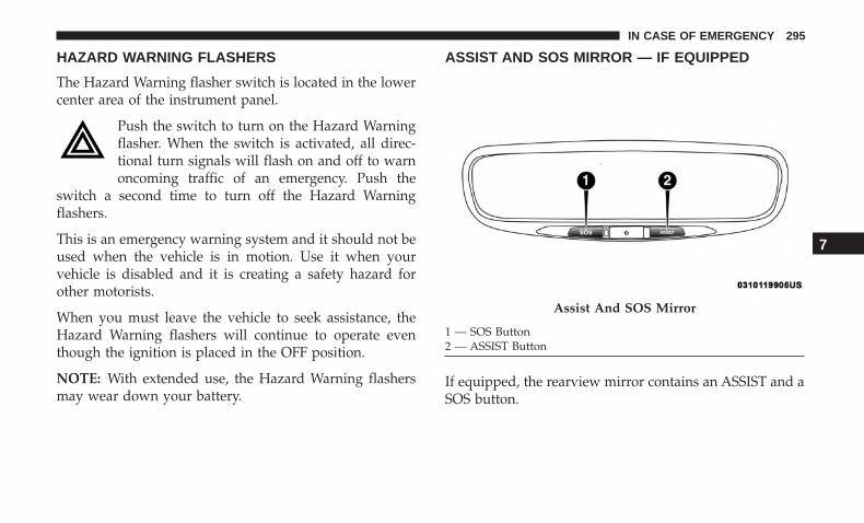
HAZARD WARNING FLASHERS
The Hazard Warning flasher switch is located in the lowercenter area of the instrument panel.
Push the switch to turn on the Hazard Warningflasher. When the switch is activated, all direc-tional turn signals will flash on and off to warnoncoming traffic of an emergency. Push the
switch a second time to turn off the Hazard Warningflashers.
This is an emergency warning system and it should not beused when the vehicle is in motion. Use it when yourvehicle is disabled and it is creating a safety hazard forother motorists.
When you must leave the vehicle to seek assistance, theHazard Warning flashers will continue to operate eventhough the ignition is placed in the OFF position.
NOTE: With extended use, the Hazard Warning flashersmay wear down your battery.
ASSIST AND SOS MIRROR — IF EQUIPPED
If equipped, the rearview mirror contains an ASSIST and aSOS button.
Assist And SOS Mirror
1 — SOS Button2 — ASSIST Button
7
IN CASE OF EMERGENCY 295
WARNING!
ALWAYS obey traffic laws and pay attention to theroad. ALWAYS drive safely with your hands on thesteering wheel. You have full responsibility and as-sume all risks related to the use of the features andapplications in this vehicle. Only use the features andapplications when it is safe to do so. Failure to do somay result in an accident involving serious injury ordeath.
NOTE:
• Your vehicle may be transmitting data as authorized bythe subscriber.
• The SOS and ASSIST buttons will only function if youare connected to an operable LTE (voice/data) or 4G(data) network. Other Uconnect services will only beoperable if your SiriusXM Guardian service is active andyou are connected to an operable LTE (voice/data) or 4G(data) network.
ASSIST Call
The ASSIST Button is used to automatically connect you toany one of the following support centers:
• Roadside Assistance – If you get a flat tire, or need a tow,just push the ASSIST button and you’ll be connected tosomeone who can help. Roadside Assistance will knowwhat vehicle you’re driving and its location. Additionalfees may apply for roadside assistance.
• SiriusXM Guardian Customer Care – In-vehicle supportfor SiriusXM Guardian.
• Vehicle Customer Care – Total support for all othervehicle issues.
SOS Call
1. Push the SOS Call button on the Rearview Mirror.
NOTE: In case the SOS Call button is pushed in error, therewill be a ten second delay before the SOS Call systeminitiates a call to a SOS operator. To cancel the SOS Callconnection, push the SOS call button on the RearviewMirror or press the cancellation button on the DeviceScreen. Termination of the SOS Call will turn off the greenLED light on the Rearview Mirror.
296 IN CASE OF EMERGENCY

2. The LED light located between the ASSIST and SOSbuttons on the Rearview Mirror will turn green once aconnection to a SOS operator has been made.
3. Once a connection between the vehicle and a SOS operatoris made, the SOS Call system may transmit the followingimportant vehicle information to a SOS operator:
• Indication that the occupant placed a SOS Call.
• The vehicle brand.
• The last known GPS coordinates of the vehicle.
4. You should be able to speak with the SOS operatorthrough the vehicle audio system to determine if addi-tional help is needed.
WARNING!
ALWAYS obey traffic laws and pay attention to theroad. ALWAYS drive safely with your hands on thesteering wheel. You have full responsibility and as-sume all risks related to the use of the features andapplications in this vehicle. Only use the features andapplications when it is safe to do so. Failure to do somay result in an accident involving serious injury ordeath.
NOTE:• Your vehicle may be transmitting data as authorized
by the subscriber.• Once a connection is made between the vehicle’s SOS
Call system and the SOS operator, the SOS operator maybe able to open a voice connection with the vehicle todetermine if additional help is needed. Once the SOSoperator opens a voice connection with the vehicle’sSOS Call system, the operator should be able to speakwith you or other vehicle occupants and hear soundsoccurring in the vehicle. The vehicle’s SOS Call systemwill attempt to remain connected with the SOS operatoruntil the SOS operator terminates the connection.
5. The SOS operator may attempt to contact appropriateemergency responders and provide them with impor-tant vehicle information and GPS coordinates.
WARNING!
• If anyone in the vehicle could be in danger (e.g., fireor smoke is visible, dangerous road conditions orlocation), do not wait for voice contact from anEmergency Services Agent. All occupants should exitthe vehicle immediately and move to a safe location.
(Continued)
7
IN CASE OF EMERGENCY 297

WARNING! (Continued)• Never place anything on or near the vehicle’s oper-
able network and GPS antennas. You could preventoperable network and GPS signal reception, whichcan prevent your vehicle from placing an emergencycall. An operable network and GPS signal receptionis required for the SOS Call system to functionproperly.
• The SOS Call system is embedded into the vehicle’selectrical system. Do not add aftermarket electricalequipment to the vehicle’s electrical system. Thismay prevent your vehicle from sending a signal toinitiate an emergency call. To avoid interference thatcan cause the SOS Call system to fail, never addaftermarket equipment (e.g., two-way mobile radio,CB radio, data recorder, etc.) to your vehicle’s electri-cal system or modify the antennas on your vehicle. IFYOUR VEHICLE LOSES BATTERY POWER FORANY REASON (INCLUDING DURING OR AFTERAN ACCIDENT), THE UCONNECT FEATURES,APPS AND SERVICES, AMONG OTHERS, WILLNOT OPERATE.
(Continued)
WARNING! (Continued)• Modifications to any part of the SOS Call system
could cause the air bag system to fail when you needit. You could be injured if the air bag system is notthere to help protect you.
SOS Call System Limitations
Vehicles sold in Mexico DO NOT have SOS Call systemcapabilities.
SOS or other emergency line operators in Mexico may notanswer or respond to SOS system calls.
If the SOS Call system detects a malfunction, any of thefollowing may occur at the time the malfunction is de-tected, and at the beginning of each ignition cycle:
• The Rearview Mirror light located between the ASSISTand SOS buttons will continuously be illuminated red.
• The Device Screen will display the following message“Vehicle device requires service. Please contact yourdealer.”
• An In-Vehicle Audio message will state “Vehicle devicerequires service. Please contact your dealer.”
298 IN CASE OF EMERGENCY

WARNING!
• Ignoring the Rearview Mirror light could mean youwill not have SOS Call services. If the RearviewMirror light is illuminated, have your authorizeddealer service the SOS Call system immediately.
• The Occupant Restraint Control module turns on theair bag Warning Light on the instrument panel if amalfunction in any part of the system is detected. Ifthe Air Bag Warning Light is illuminated, have yourauthorized dealer service the Occupant RestraintControl system immediately.
Even if the SOS Call system is fully functional, factorsbeyond FCA US LLC’s control may prevent or stop the SOSCall system operation. These include, but are not limitedto, the following factors:
• Delayed accessories mode is active.
• The ignition is in the OFF position.
• The vehicle’s electrical systems are not intact.
• The SOS Call system software and/or hardware aredamaged during a crash.
• The vehicle battery loses power or becomes discon-nected during a vehicle crash.
• LTE (voice/data) or 4G (data) network and/or GlobalPositioning Satellite signals are unavailable or ob-structed.
• Equipment malfunction at the SOS operator facility.
• Operator error by the SOS operator.
• LTE (voice/data) or 4G (data) network congestion.
• Weather.
• Buildings, structures, geographic terrain, or tunnels.
WARNING!
ALWAYS obey traffic laws and pay attention to theroad. ALWAYS drive safely with your hands on thesteering wheel. You have full responsibility and as-sume all risks related to the use of the features andapplications in this vehicle. Only use the features andapplications when it is safe to do so. Failure to do somay result in an accident involving serious injury ordeath.
7
IN CASE OF EMERGENCY 299

NOTE:
• Your vehicle may be transmitting data as authorized bythe subscriber.
• Never place anything on or near the vehicle’s LTE(voice/data) or 4G (data) and GPS antennas. You couldprevent LTE (voice/data) or 4G (data) and GPS signalreception, which can prevent your vehicle from placingan emergency call. An operable LTE (voice/data) or 4G(data) network connection and a GPS signal is requiredfor the SOS Call system to function properly.
General Information
This device complies with Part 15 of the FCC Rules.Operation is subject to the following two conditions: (1)This device may not cause harmful interference, and (2)this device must accept any interference received, includ-ing interference that may cause undesired operation.
NOTE: Changes or modifications not expressly approvedby the party responsible for compliance could void theuser’s authority to operate the equipment.
CAUTION!
To avoid damage to the mirror during cleaning, neverspray any cleaning solution directly onto the mirror.Apply the solution onto a clean cloth and wipe themirror clean.
300 IN CASE OF EMERGENCY

BULB REPLACEMENTReplacement Bulbs
Interior Bulbs
Lamps Bulb NumberFront Courtesy Light C5W
Front Courtesy Lights (Sun Visors) C5WRear Dome Light (Models Without Retractable roof) C5WRear Interior Lights (Models With Retractable roof) C5W
Interior Lights HT-168Dome Light (Glove Box) HT-168
Exterior Bulbs
Lamps Bulb NumberLow Beam Headlamps (Halogen) H11LLHigh Beam Headlamps (Halogen) 9005LL
Front Position/Daytime Running Lights (DRL ) PSX24WFront Direction Indicator Lamps 7444NAFront Position – Premium LED LED (Serviced At An Authorized Dealer)
Front Fog Lamps H11LLLow Beam / High Beam Headlamps (HID) D3S (HID) (Serviced At An Authorized Dealer)
Side Indicators (Front – Halogen) W5W
7
IN CASE OF EMERGENCY 301

Lamps Bulb NumberSide Indicators (Front – HID) LED (Serviced At An Authorized Dealer)
Side Indicators (Side View Mirror) LED (Serviced At An Authorized Dealer)Tail/Brake Lights Premium Tail Lights: LED (Serviced At An Authorized
Dealer)Base Tail Lights: W21/5WLL-M
Turn Indicators W21WLL For Premium Tail LampsW21/5WLL For Base Tail Lamps
Center High Mounted Stop Lamp (CHMSL) LED (Serviced At An Authorized Dealer)License Plate Lamp LED (Serviced At An Authorized Dealer)
Liftgate Lamp Reverse W21WLLLiftgate Lamp Tail LED (Serviced At An Authorized Dealer)
302 IN CASE OF EMERGENCY

High Intensity Discharge (HID) Headlamps — IfEquipped
The headlamps contain a type of high voltage dischargelight source. High voltage can remain in the circuit evenwith the headlamp switch off. Because of this, you shouldnot attempt to service a HID headlamp light source your-self. If an HID headlamp light source fails, take yourvehicle to an authorized dealer for service.
NOTE: On vehicles equipped with HID headlamps, whenthe headlamps are turned on, there is a blue hue to thelights. This diminishes and becomes more white afterapproximately 10 seconds, as the system charges.
WARNING!
A transient high voltage occurs at the bulb sockets ofHID headlamps when the headlamp switch is turnedON. It may cause serious electrical shock or electrocu-tion if not serviced properly. See your authorizeddealer for service.
Replacing Exterior Bulbs
Headlamps
Hi/Lo Beam Light Halogen
The bulbs can be accessed from the wheel liner with thefollowing procedure:
1. Turn the front wheels completely.
2. Remove the wheel liner.
3. Remove the headlamp bulb cap.
4. Rotate the headlamp bulb socket counterclockwise thenpull outwards.
Headlamp
1 — Low Beam Bulb Cap2 — High Beam Bulb Cap
7
IN CASE OF EMERGENCY 303

5. Push on the locking tab on the headlamp bulb connectorand remove the bulb and socket.
6. Install the new headlamp bulb making sure it’s properlylocked.
7. Install the headlamp bulb and socket; turn it clockwisemaking sure it is properly locked.
8. Reinstall the wheel liner.
NOTE: We advise referring to an authorized dealer.
WARNING!
Carry out the operation of replacing lamps only withthe engine off. Also make sure that the engine is cold,to avoid the danger of burns.
Turn Signal Light/Position Lights/Daytime RunningLights
To replace the bulbs proceed as follows:
1. Turn the front wheels completely.
2. Remove the wheel liner.
3. Remove the electrical connectors.
4. For the DRL bulb, grip the bulb at the top and bottomlocking tabs and squeeze to and remove the bulb.
5. To replace the DRL bulb gently push bulb towardshousing. Be sure to hear both the top and bottomlocking tabs “CLICK” to ensure the bulb is properlyseated.
6. For the turn signal bulb, rotate in a counterclockwisedirection and remove the bulb and bulb socket. Pull thebulb axially to remove it from the socket.
Headlamp Bulb Socket
304 IN CASE OF EMERGENCY

7. Install the bulb and sockets and rotate them clockwisemaking sure that it is properly locked.
8. Reconnect the electrical connectors.
9. Reinstall the wheel liner.
NOTE: We advise referring to an authorized dealer.
Front Fog Lights
To replace the bulbs proceed as follows:
1. Turn the front wheels completely.
2. Remove the wheel liner.
3. By pushing the electrical connector tab remove theelectrical connector.
4. Rotate the bulb counterclockwise, and then replace thebulb.
5. Insert the new bulb in the socket, making sure the bulbis locked into place.
6. Reconnect the electrical connector.
7. Reinstall the wheel liner.
NOTE: We advise referring to an authorized dealer.
Fog Lamp Housing
1 — Bulb
7
IN CASE OF EMERGENCY 305

Side Indicators
The Side Indicators are LED. For their replacement seeyour authorized dealer.
Rear Body Side Tail Lamps
Contain the following:
• Position lights
• Stop lights
• Direction indicator
To replace the bulbs proceed as follows:
1. Open the liftgate.
2. Using a suitable tool remove fasteners.
3. Disconnect the electrical connector by pushing the re-lease.
4. Remove the rear body side tail lamp, sliding it awayfrom the back of the vehicle.
Body Side Tail Lamp Opening
1 — Fasteners
306 IN CASE OF EMERGENCY

5. Replace the bulb as necessary by turning and removingthe bulb housing. 6. Insert the new bulb, making sure it is properly locked.
7. Reposition the rear body side lamp assembly on the car.
8. Reconnect the electrical connector.
9. Reinstall the body side lamp making sure to align theball studs.
Body Side Tail Lamp
1 — Rear Body Side Tail Lamp2 — Ball Stud
Reverse Side of Tail Lamp
1 — Direction Indicator Bulb / Stop Lamp Bulb2 — Electrical Connector3 — Ball Studs
7
IN CASE OF EMERGENCY 307

10. Install fasteners and tighten body side lamp assembly.
11. Finally close the tailgate.
Reverse Lamps
1. Open the liftgate.
2. Using a suitable tool remove the access panel for bodyside lamps, remove lift gate access cover for lift gatelamps.
3. Disconnect the electrical connector by pushing the re-lease.
4. Remove bulb and replace making sure it is properlylocked.
5. Reconnect the electrical connector.
6. Reinstall the access panels making sure they are lockedin correctly.
Body Side Tail Lamp
1 — Rear Body Side Tail Lamp2 — Ball Stud
Liftgate
1 — Lift Gate Access Covers
308 IN CASE OF EMERGENCY

7. Finally close the tailgate.
3rd Stop Lamp
The CHMSL is LED. For their replacement, see yourauthorized dealer.
License Plate Lights
The License Plate light is LED. For their replacement, seeyour authorized dealer.
Replacing Interior Bulbs
Front Courtesy Light
To replace the bulbs proceed as follows:
1. Using a suitable tool remove the front courtesy lightassemby.
2. Release the retainer clips and bulb housing as shown.Front Courtesy Light
7
IN CASE OF EMERGENCY 309
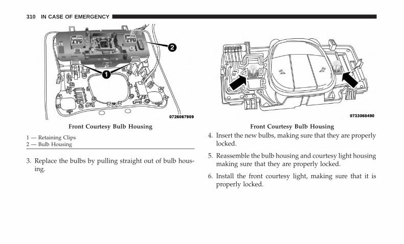
3. Replace the bulbs by pulling straight out of bulb hous-ing.
4. Insert the new bulbs, making sure that they are properlylocked.
5. Reassemble the bulb housing and courtesy light housingmaking sure that they are properly locked.
6. Install the front courtesy light, making sure that it isproperly locked.
Front Courtesy Bulb Housing
1 — Retaining Clips2 — Bulb Housing
Front Courtesy Bulb Housing
310 IN CASE OF EMERGENCY

Dome Light Vanity Mirror — If Equipped
To replace the bulbs proceed as follows:
1. Lift the cover of the mirror and pull out the mirror framewith the mirror light cover attached.
2. Replace the bulb, releasing it from the side contacts, andthen insert the new bulb, making sure that it is properlylocked between the contacts.
3. Reinstall the visor mirror light cover making sure that itis properly locked.
4. Finally lower the visor mirror cover to the mirror.
Dome Light Glove Compartment
To replace the bulb proceed as follows:
1. Open the glove compartment.
2. Place your fingers inside the light assembly, pull thebulb to replace it.
3. Insert the new bulb, making sure it is properly locked.
Visor
1 — Visor Mirror Cover2 — Visor Mirror Light Bulb Removal/Installation
7
IN CASE OF EMERGENCY 311

Dome Light
To replace the bulbs proceed as follows:
1. Lower the handle in the direction shown; remove thedome light.
2. Replace the bulb by removing it from the side contacts.
3. Insert the new bulb, locking it between the contacts.
4. Reinstall the dome light.
Grab Handle/Dome Light
Bulb
312 IN CASE OF EMERGENCY

Interior Cargo Lights
To replace the bulbs proceed as follows:
1. Using thumb with slight pressure – push bulb holder tothe side.
2. Fully disengage the bulb holder from the housing.Bulb Holder
Bulb Holder
7
IN CASE OF EMERGENCY 313

3. Rotate bulb holder to replace bulb.
WARNING!
• Modifications or repair of the electrical system per-formed incorrectly and without taking into accountthe technical characteristics can cause malfunctionswith the risk of fire.
• Halogen lamps contain gas under pressure, in theevent of breakage be careful of the projection offragments of glass.
• Halogen lamps must be handled by touching onlythe metallic part. If the transparent bulb is in contact
(Continued)
WARNING! (Continued)with the fingers, reduces the intensity of the emittedlight and you can also affect the life of the lamp. Incase of accidental contact, rub the bulb with a clothdampened with alcohol and allow to dry.
NOTE: It is recommended to have your bulbs replaced byyour authorized dealer.
FUSES
WARNING!
• When replacing a blown fuse, always use an appro-priate replacement fuse with the same amp rating asthe original fuse. Never replace a fuse with anotherfuse of higher amp rating. Never replace a blownfuse with metal wires or any other material. Do notplace a fuse inside a circuit breaker cavity or viceversa. Failure to use proper fuses may result inserious personal injury, fire and/or property damage.
• Before replacing a fuse, make sure that the ignition isoff and that all the other services are switched offand/or disengaged.
(Continued)
Bulb
314 IN CASE OF EMERGENCY

WARNING! (Continued)• If the replaced fuse blows again, contact an autho-
rized dealer.• If a general protection fuse for safety systems (air
bag system, braking system), power unit systems(engine system, transmission system) or steeringsystem blows, contact an authorized dealer.
General Information
The fuses protect electrical systems against excessive cur-rent.
When a device does not work, you must check the fuseelement inside the blade fuse for a break/melt.
Also, please be aware that when using power outlets forextended periods of time with the engine off may result invehicle battery discharge.
Blade Fuses
1 — Fuse Element2 — Blade Fuse with a good/functional fuse element.3 — Blade fuse with a NOT functional / BAD fuse element (blownfuse).
7
IN CASE OF EMERGENCY 315

Fuse Location
The fuses are grouped into controllers located in the enginecompartment.
Engine Compartment Fuses/Distribution Unit
The engine compartment fuse panel is located on the leftside of the engine compartment.
Removing Fuse Cover and Locking Screw
Proceed as follows:
1. Slowly turn the screw counterclockwise.
2. Slowly release the screw.
3. Remove the fuse cover by sliding it upward.
Fuse Panel & Cover Location
1 — Cover Screw2 — Fuse Cover
316 IN CASE OF EMERGENCY
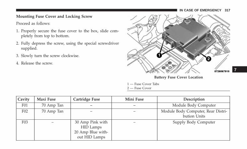
Mounting Fuse Cover and Locking Screw
Proceed as follows:
1. Properly secure the fuse cover to the box, slide com-pletely from top to bottom.
2. Fully depress the screw, using the special screwdriversupplied.
3. Slowly turn the screw clockwise.
4. Release the screw.
Cavity Maxi Fuse Cartridge Fuse Mini Fuse DescriptionF01 70 Amp Tan – – Module Body ComputerF02 70 Amp Tan – – Module Body Computer, Rear Distri-
bution UnitsF03 – 30 Amp Pink with
HID Lamps20 Amp Blue with-
out HID Lamps
– Supply Body Computer
Battery Fuse Cover Location
1 — Fuse Cover Tabs2 — Fuse Cover
7
IN CASE OF EMERGENCY 317

Cavity Maxi Fuse Cartridge Fuse Mini Fuse DescriptionF04 – 40 Amp Tan – Brake Control Electronics ModuleF05 – 40 Amp Tan – PTC HeaterF06 40 Amp Orange – – Starter RelayF07 40 Amp Orange – – Rear Distribution Unit For Trailer Tow
UsageF08 – 30 Amp Pink – Supply for F24, F87, Steering ControlF09 – – 7.5 Amp Brown Control Module EngineF10 – – 20 Amp Yellow HornF11 – – 20 Amp Yellow – 1.4L
Gas & Diesel Engines25 Amp Clear – 2.4 L
Engines
Supply Secondary Loads
F14 – – 7.5 Amp Brown Diesel Crankcase HeaterF15 40 Amp Orange – – Brake Control Module PumpF16 – – 10 Amp Red Engine Control Module Power, Auto-
matic TransmissionF17 – – 10 Amp Red Engine Secondary LoadsF18 – – 20 Amp Yellow 12V Rear Cargo Outlet Ignition Pow-
eredF19 – – 7.5 Amp Brown Air Conditioner Compressor and
PWM Rad Fan enable
318 IN CASE OF EMERGENCY

Cavity Maxi Fuse Cartridge Fuse Mini Fuse DescriptionF20 – – 20 Amp Yellow Cigar LighterF21 – – 15 Amp Blue Fuel PumpF22 – – 20 Amp Yellow – Gas
Engine15 Amp Blue – Diesel
Engine
Power Control Module Engine
F23 – – 30 Amp Green Window Heater GridF24 – – 15 Amp Blue Electronic Unit Supply Automatic
TransmissionF30 – – 20 Amp Yellow (Cus-
tomer Selectable,Move From F18)
12V Rear Cargo Outlet Constant Bat-tery Powered
F81 60 Amp Blue – – Glow Plug ModuleF82 – 40 Amp Green – Diesel Fuel Filter HeaterF83 – 40 Amp Green – HVAC FanF84 – – 30 Amp Green Power Supply All Wheel DriveF87 – – 5 Amp Tan Gear Selector Automatic TransmissionF88 – – 7.5 Amp Brown Heated Outside MirrorsF89 – – 30 Amp Green Heated Rear WindowF90 – – 5 Amp Tan IBS Sensor (Battery State Of Charge)Fxx – – 10 Amp Red Dual Battery Control Relay
7
IN CASE OF EMERGENCY 319
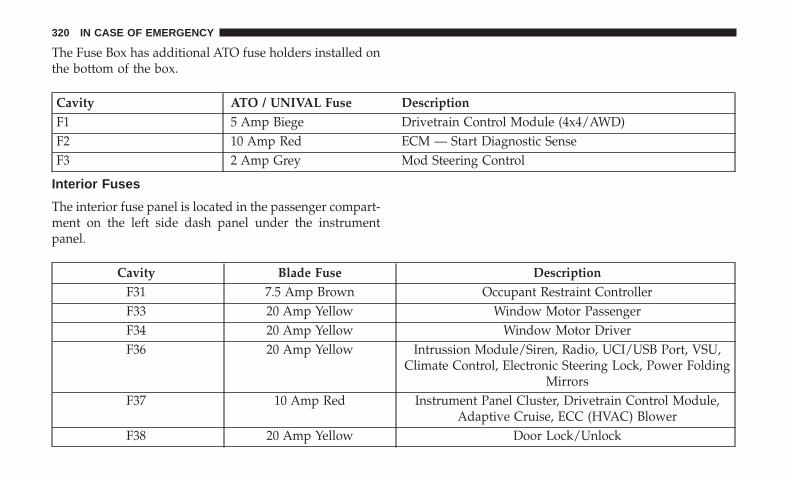
The Fuse Box has additional ATO fuse holders installed onthe bottom of the box.
Cavity ATO / UNIVAL Fuse DescriptionF1 5 Amp Biege Drivetrain Control Module (4x4/AWD)F2 10 Amp Red ECM — Start Diagnostic SenseF3 2 Amp Grey Mod Steering Control
Interior Fuses
The interior fuse panel is located in the passenger compart-ment on the left side dash panel under the instrumentpanel.
Cavity Blade Fuse DescriptionF31 7.5 Amp Brown Occupant Restraint ControllerF33 20 Amp Yellow Window Motor PassengerF34 20 Amp Yellow Window Motor DriverF36 20 Amp Yellow Intrussion Module/Siren, Radio, UCI/USB Port, VSU,
Climate Control, Electronic Steering Lock, Power FoldingMirrors
F37 10 Amp Red Instrument Panel Cluster, Drivetrain Control Module,Adaptive Cruise, ECC (HVAC) Blower
F38 20 Amp Yellow Door Lock/Unlock
320 IN CASE OF EMERGENCY

Cavity Blade Fuse DescriptionF42 7.5 Amp Brown Brake System Module, Electric Power SteeringF43 20 Amp Yellow Washer Pump Front And RearF47 20 Amp Yellow Rear Left Window LifterF48 20 Amp Yellow Rear Right Window LifterF49 7.5 Amp Brown Park Assist, Blind Spot, Voltage Stabilizer, Humidity Sen-
sor, Sunroof, Electronic Steering Lock, Temp Sense, Mir-ror, Heated Seats, Light And Rain Sensor
F50 7.5 Amp Brown Occupant Restraint ControllerF51 7.5 Amp Brown Electronic Climate Control, Occupant Classification, Rear
View Camera, Climate Control, Headlamp Leveling, Ter-rain Select, Heated Rear Window, Trailer Tow, Haptic
Lane DepartureF53 7.5 Amp Brown Keyless Ignition Node Module, Electric Park Brake, RF
Hub, ClusterF94 15 Amp Blue ECC (HVAC) Blower, Lumbar Adjust Driver Seat, Power
Outlets
7
IN CASE OF EMERGENCY 321

Rear Cargo Fuse/Relay Distribution Unit
To access the fuses, remove the access door from the leftrear panel of the rear cargo area.
The fuses may be contained in two units. Fuse holder No.1 is located closest to the rear of the vehicle and fuse holderNo. 2 (if equipped with trailer towing) is located closest tothe front of the vehicle.
Fuse Holder No. 1
Cavity Mini Fuse DescriptionF1 30 Amp Green Power InverterF2 30 Amp Green Memory SeatF3 20 Amp Yellow Sun Roof – If EquippedF4 30 Amp Green Power Seat (Passenger Side)F5 30 Amp Green Power Seat (Driver Side)
Rear Cargo Fuse Cavities
1 — Fuse Holder No. 12 — Fuse Holder No. 2
322 IN CASE OF EMERGENCY

Cavity Mini Fuse DescriptionF6 7.5 Amp Brown Power Lumbar (Power Seats)F7 15 Amp Blue Heated Steering Wheel / Ventilated SeatsF8 20 Amp Yellow Heated Seats
Fuse Holder No. 2
Cavity Mini Fuse DescriptionF1 10 Amp Red Controller Exterior Lighting On TrailerF5 15 Amp Blue Controller Exterior Lighting Lights (Drivers Side)F6 15 Amp Blue Controller Exterior Lighting Lights (Passenger Side)F7 10 Amp Red TTM Jumper Battery Feed
On the Rear Cargo Fuse/Relay Distribution Unit bracket,there is a Maxi Fuse holder for the Power Liftgate and anATO / Uni Val fuse holder for the HIFI Audio System.
Cavity Maxi Fuse DescriptionF01 30 Amp Green Power Liftgate
Cavity ATO / Uni-Val Fuse DescriptionF02 25 Amp Clear HIFI Audio System
7
IN CASE OF EMERGENCY 323

JACKING AND TIRE CHANGING
WARNING!
• Do not attempt to change a tire on the side of thevehicle close to moving traffic. Pull far enough offthe road to avoid the danger of being hit whenoperating the jack or changing the wheel.
• Being under a jacked-up vehicle is dangerous. Thevehicle could slip off the jack and fall on you. Youcould be crushed. Never put any part of your bodyunder a vehicle that is on a jack. If you need to getunder a raised vehicle, take it to a service centerwhere it can be raised on a lift.
• Never start or run the engine while the vehicle is ona jack.
• The jack is designed to be used as a tool for changingtires only. The jack should not be used to lift thevehicle for service purposes. The vehicle should bejacked on a firm level surface only. Avoid ice orslippery areas.
Jack Location/Spare Tire Stowage
If equipped, the jack and tools are located in the rearstorage compartment, below the spare tire.
Jack And Tools Location
1 — Jack2 — Alignment Pin3 — Wheel Bolt Wrench4 — Emergency Funnel5 — Screwdriver
324 IN CASE OF EMERGENCY

1. Open the liftgate.
2. Lift the access cover using the load floor handle.
3. Remove the fastener securing the spare tire, and removethe spare wheel from the vehicle. The jack and tools willbe found beneath.
4. Remove the alignment pin from the middle, rotate thejack counterclockwise, and lift it from the foam tray.
5. Remove the jack and wheel bolt wrench.Load Floor Handle
Spare Tire Fastener
7
IN CASE OF EMERGENCY 325

WARNING!
A loose tire or jack thrown forward in a collision orhard stop could endanger the occupants of the vehicle.Always stow the jack parts and the spare tire in theplaces provided. Have the deflated (flat) tire repairedor replaced immediately.
Preparations For Jacking
1. Park the vehicle on a firm level surface as far from theedge of the roadway as possible. Avoid icy or slipperyareas.
WARNING!
Do not attempt to change a tire on the side of thevehicle close to moving traffic. Pull far enough off theroad to avoid being hit when operating the jack orchanging the wheel.
2. Turn on the Hazard Warning flasher.
3. Apply the parking brake.
4. Place the gear selector into PARK (automatic transmis-sion) or REVERSE (manual transmission).
5. Turn the ignition off to the OFF position.
Jack And Tools1 — Wheel Bolt Wrench2 — Jack3 — Emergency Funnel4 — Screwdriver5 — Alignment Pin
326 IN CASE OF EMERGENCY

6. Block both the front and rear of the wheel diagonallyopposite the jacking position. For example, if the rightfront wheel is being changed, block the left rear wheel.
NOTE: Passengers should not remain in thevehicle when the vehicle is being jacked.
Jacking Instructions
WARNING!
Carefully follow these tire changing warnings to helpprevent personal injury or damage to your vehicle:• Always park on a firm, level surface as far from the
edge of the roadway as possible before raising thevehicle.
• Turn on the Hazard Warning flasher.• Block the wheel diagonally opposite the wheel to be
raised.• Apply the parking brake firmly and set the transmis-
sion in PARK.
(Continued)
WARNING! (Continued)• Never start or run the engine with the vehicle on a
jack.• Do not let anyone sit in the vehicle when it is on a
jack.• Do not get under the vehicle when it is on a jack. If
you need to get under a raised vehicle, take it to aservice center where it can be raised on a lift.
• Only use the jack in the positions indicated and forlifting this vehicle during a tire change.
• If working on or near a roadway, be extremelycareful of motor traffic.
• To assure that spare tires, flat or inflated, are securelystowed, spares must be stowed with the valve stemfacing the ground.
7
IN CASE OF EMERGENCY 327

CAUTION!
Do not attempt to raise the vehicle by jacking onlocations other than those indicated in the JackingInstructions for this vehicle.
1. Remove the spare tire, jack, and wheel bolt wrench.
2. If equipped with aluminum wheels where the center capcovers the wheel bolts, use the wheel bolt wrench to prythe center cap off carefully before raising the vehicle.
3. Before raising the vehicle, use the wheel bolt wrench toloosen, but not remove, the wheel bolts on the wheelwith the flat tire. Turn the wheel bolts counterclockwiseone turn while the wheel is still on the ground.
4. Place the jack underneath the lift area that is closest tothe flat tire. Turn the jack screw clockwise to firmlyengage the jack saddle with the lift area of the sill flange,centering the jack saddle inside the cutout in the sillcladding.
Jack Warning Label
Jacking Locations
328 IN CASE OF EMERGENCY

5. Raise the vehicle just enough to remove the flat tire.
WARNING!
Raising the vehicle higher than necessary can make thevehicle less stable. It could slip off the jack and hurtsomeone near it. Raise the vehicle only enough toremove the tire.
6. Remove the wheel bolts and tire.
Rear Jacking Location Front Jacking Location
7
IN CASE OF EMERGENCY 329

7. Remove the alignment pin from the jack assembly andthread the pin into the wheel hub to assist in mountingthe spare tire.
8. Mount the spare tire.
CAUTION!
Be sure to mount the spare tire with the valve stemfacing outward. The vehicle could be damaged if thespare tire is mounted incorrectly.
NOTE:
• For vehicles equipped, do not attempt to install acenter cap or wheel cover on the compact spare.
• Refer to “Compact Spare Tire” and to “Limited-UseSpare” under “Tires—General Information” in “Servic-ing And Maintenance” for additional warnings, cau-tions, and information about the spare tire, its use, andoperation.
9. Install and lightly tighten the wheel bolts.
WARNING!
To avoid the risk of forcing the vehicle off the jack, donot tighten the wheel nuts fully until the vehicle hasbeen lowered. Failure to follow this warning mayresult in serious injury.
10. Lower the vehicle to the ground by turning the jackhandle counterclockwise.
11. Finish tightening the wheel bolts. Push down on thewrench while at the end of the handle for increasedleverage. Tighten the wheel bolts in a star pattern untileach wheel bolt has been tightened twice. Refer to“Wheel And Tire Torque Specifications” in “TechnicalMounting Spare Tire
330 IN CASE OF EMERGENCY

Specifications” for the proper lug bolt torque. If indoubt about the correct tightness, have them checkedwith a torque wrench by your authorized dealer or at aservice station.
12. Place the jack on the foam tray and open it far enoughso that it is secured. Once placed in position, rotate itclockwise to lock it in. Replace the alignment pin in thecenter hole to lock the jack in place.
WARNING!
A loose tire or jack thrown forward in a collision orhard stop could endanger the occupants of the vehicle.Always stow the jack parts and the spare tire in theplaces provided. Have the deflated (flat) tire repairedor replaced immediately.
Road Tire Installation
1. Mount the road tire on the axle.
2. Install the remaining wheel bolts with the threaded endof the wheel bolt toward the wheel. Lightly tighten thewheel bolts.
WARNING!
To avoid the risk of forcing the vehicle off the jack, donot tighten the wheel bolts fully until the vehicle hasbeen lowered. Failure to follow this warning mayresult in serious injury.
3. Lower the vehicle to the ground by turning the jackhandle counterclockwise.
4. Finish tightening the wheel bolts. Push down on thewrench while at the end of the handle for increasedleverage. Tighten the wheel bolts in a star pattern untileach wheel bolt has been tightened twice. Refer to“Wheel And Tire Torque Specifications” in “TechnicalSpecifications” for the proper lug bolt torque. If in doubtabout the correct tightness, have them checked with atorque wrench by your authorized dealer or servicestation.
5. Lower the jack until it is free. Remove the wheel blocks.Reassemble the lug wrench to the jack assembly andstow it in the spare tire area. Secure the assembly usingthe means provided. Release the parking brake beforedriving the vehicle.
7
IN CASE OF EMERGENCY 331
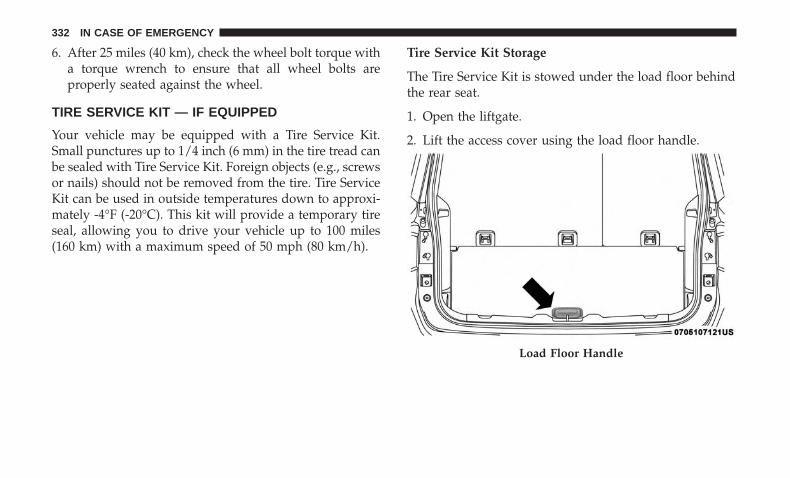
6. After 25 miles (40 km), check the wheel bolt torque witha torque wrench to ensure that all wheel bolts areproperly seated against the wheel.
TIRE SERVICE KIT — IF EQUIPPED
Your vehicle may be equipped with a Tire Service Kit.Small punctures up to 1/4 inch (6 mm) in the tire tread canbe sealed with Tire Service Kit. Foreign objects (e.g., screwsor nails) should not be removed from the tire. Tire ServiceKit can be used in outside temperatures down to approxi-mately -4°F (-20°C). This kit will provide a temporary tireseal, allowing you to drive your vehicle up to 100 miles(160 km) with a maximum speed of 50 mph (80 km/h).
Tire Service Kit Storage
The Tire Service Kit is stowed under the load floor behindthe rear seat.
1. Open the liftgate.
2. Lift the access cover using the load floor handle.
Load Floor Handle
332 IN CASE OF EMERGENCY
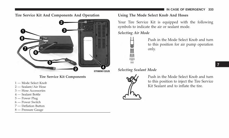
Tire Service Kit And Components And Operation Using The Mode Select Knob And Hoses
Your Tire Service Kit is equipped with the followingsymbols to indicate the air or sealant mode.
Selecting Air Mode
Push in the Mode Select Knob and turnto this position for air pump operationonly.
Selecting Sealant Mode
Push in the Mode Select Knob and turnto this position to inject the Tire ServiceKit Sealant and to inflate the tire.
Tire Service Kit Components
1 — Mode Select Knob2 — Sealant/Air Hose3 — Hose Accessories4 — Sealant Bottle5 — Power Plug6 — Power Switch7 — Deflation Button8 — Pressure Gauge
7
IN CASE OF EMERGENCY 333

Using The Power Button
Push and release the Power Button onceto turn On the Tire Service Kit. Push andrelease the Power Button again to turnOff the Tire Service Kit.
Using The Deflation Button
Push the Deflation Button to reduce theair pressure in the tire if it becomesover-inflated.
Tire Service Kit Usage Precautions
• Replace the Tire Service Kit Sealant Bottle prior to theexpiration date (printed at the lower right hand corneron the bottle label) to assure optimum operation of thesystem. Refer to “Sealant Bottle Replacement” in thissection.
• The Sealant Bottle is a one tire application use and needsto be replaced after each use. Always replace thesecomponents immediately at your original equipmentvehicle dealer.
• When the Tire Service Kit sealant is in a liquid form,clean water, and a damp cloth will remove the materialfrom the vehicle or tire and wheel components. Once thesealant dries, it can easily be peeled off and properlydiscarded.
• For optimum performance, make sure the valve stem onthe wheel is free of debris before connecting the TireService Kit.
• You can use the Tire Service Kit air pump to inflatebicycle tires. The kit also comes with two needles,located in the Accessory Storage Compartment (on thebottom of the air pump) for inflating sport balls, rafts, orsimilar inflatable items. However, use only the Air Pumpand make sure the Mode Select Knob is in the Air Modewhen inflating such items to avoid injecting sealant intothem. The Tire Service Kit Sealant is only intended toseal punctures less than 1/4 inch (6 mm) diameter in thetread of your vehicle.
• Do not lift or carry the Tire Service Kit by the hoses.
334 IN CASE OF EMERGENCY

WARNING!
• Do not attempt to seal a tire on the side of the vehicleclosest to traffic. Pull far enough off the road to avoidthe danger of being hit when using the Tire Service Kit.
• Do not use Tire Service Kit or drive the vehicle underthe following circumstances:– If the puncture in the tire tread is approximately
1/4 inch (6 mm) or larger.– If the tire has any sidewall damage.– If the tire has any damage from driving with
extremely low tire pressure.– If the tire has any damage from driving on a flat tire.– If the wheel has any damage.– If you are unsure of the condition of the tire or the
wheel.• Keep Tire Service Kit away from open flames or heat
source.• A loose Tire Service Kit thrown forward in a collision
or hard stop could endanger the occupants of the
(Continued)
WARNING! (Continued)vehicle. Always stow the Tire Service Kit in the placeprovided. Failure to follow these warnings can resultin injuries that are serious or fatal to you, yourpassengers, and others around you.
• Take care not to allow the contents of Tire Service Kitto come in contact with hair, eyes, or clothing. TireService Kit sealant is harmful if inhaled, swallowed,or absorbed through the skin. It causes skin, eye, andrespiratory irritation. Flush immediately with plentyof water if there is any contact with eyes or skin.Change clothing as soon as possible, if there is anycontact with clothing.
• Tire Service Kit Sealant solution contains latex. In caseof an allergic reaction or rash, consult a physicianimmediately. Keep Tire Service Kit out of reach ofchildren. If swallowed, rinse mouth immediately withplenty of water and drink plenty of water. Do notinduce vomiting! Consult a physician immediately.
7
IN CASE OF EMERGENCY 335
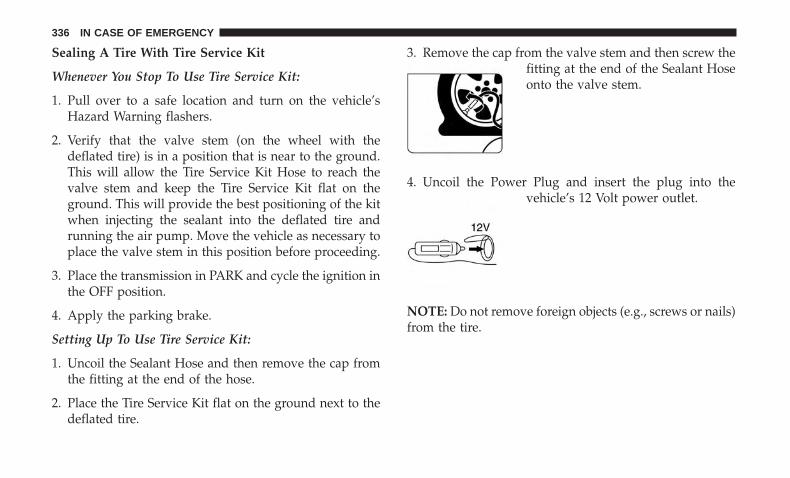
Sealing A Tire With Tire Service Kit
Whenever You Stop To Use Tire Service Kit:
1. Pull over to a safe location and turn on the vehicle’sHazard Warning flashers.
2. Verify that the valve stem (on the wheel with thedeflated tire) is in a position that is near to the ground.This will allow the Tire Service Kit Hose to reach thevalve stem and keep the Tire Service Kit flat on theground. This will provide the best positioning of the kitwhen injecting the sealant into the deflated tire andrunning the air pump. Move the vehicle as necessary toplace the valve stem in this position before proceeding.
3. Place the transmission in PARK and cycle the ignition inthe OFF position.
4. Apply the parking brake.
Setting Up To Use Tire Service Kit:
1. Uncoil the Sealant Hose and then remove the cap fromthe fitting at the end of the hose.
2. Place the Tire Service Kit flat on the ground next to thedeflated tire.
3. Remove the cap from the valve stem and then screw thefitting at the end of the Sealant Hoseonto the valve stem.
4. Uncoil the Power Plug and insert the plug into thevehicle’s 12 Volt power outlet.
NOTE: Do not remove foreign objects (e.g., screws or nails)from the tire.
336 IN CASE OF EMERGENCY
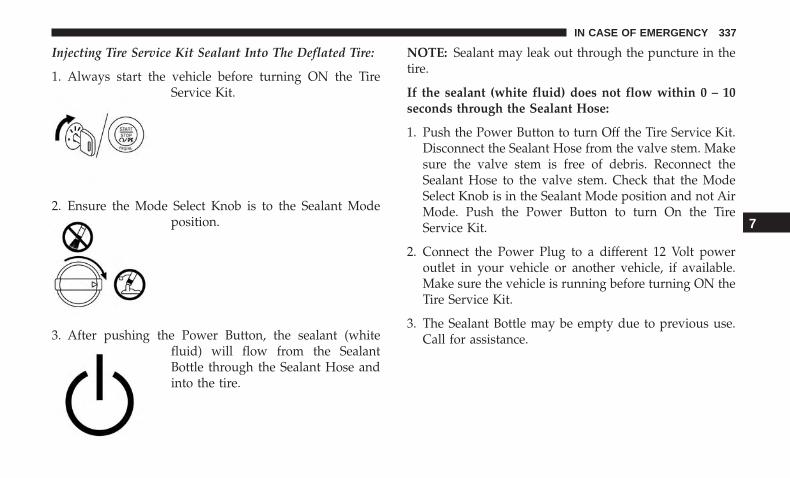
Injecting Tire Service Kit Sealant Into The Deflated Tire:
1. Always start the vehicle before turning ON the TireService Kit.
2. Ensure the Mode Select Knob is to the Sealant Modeposition.
3. After pushing the Power Button, the sealant (whitefluid) will flow from the SealantBottle through the Sealant Hose andinto the tire.
NOTE: Sealant may leak out through the puncture in thetire.
If the sealant (white fluid) does not flow within 0 – 10seconds through the Sealant Hose:
1. Push the Power Button to turn Off the Tire Service Kit.Disconnect the Sealant Hose from the valve stem. Makesure the valve stem is free of debris. Reconnect theSealant Hose to the valve stem. Check that the ModeSelect Knob is in the Sealant Mode position and not AirMode. Push the Power Button to turn On the TireService Kit.
2. Connect the Power Plug to a different 12 Volt poweroutlet in your vehicle or another vehicle, if available.Make sure the vehicle is running before turning ON theTire Service Kit.
3. The Sealant Bottle may be empty due to previous use.Call for assistance.
7
IN CASE OF EMERGENCY 337

If the sealant (white fluid) does flow through the SealantHose:
1. Continue to operate the pump until sealant is no longerflowing through hose (typically takes30 - 70 seconds). As the sealant flowsthrough the Sealant Hose, the Pres-sure Gauge can read as high as 70 psi(4.8 Bar). The Pressure Gauge willdecrease quickly from approximately70 psi (4.8 Bar) to the actual tirepressure when the Sealant Bottle isempty.
2. The pump will start to inject air into the tire immedi-ately after the Sealant Bottle is empty.Continue to operate the pump andinflate the tire to the cold tire inflationpressure found on the tire and load-ing information label located in thedriver-side door opening. Check thetire pressure by looking at the Pres-sure Gauge.
If the tire does not inflate to at least 26 psi (1.8 Bar)pressure within 15 minutes:
• The tire is too badly damaged. Do not attempt to drivethe vehicle further. Call for assistance.
If the tire inflates to the recommended pressure or is atleast 26 psi (1.8 Bar) pressure within 15 minutes:
NOTE: If the tire becomes over-inflated, push the DeflationButton to reduce the tire pressure to the recommendedinflation pressure before continuing.
1. Push the Power Button to turn off the Tire Service Kit.
2. Remove the speed limit label from the Tire Service Kitand place sticker on the steeringwheel.
338 IN CASE OF EMERGENCY
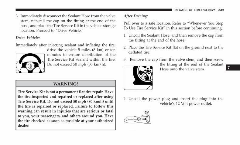
3. Immediately disconnect the Sealant Hose from the valvestem, reinstall the cap on the fitting at the end of thehose, and place the Tire Service Kit in the vehicle storagelocation. Proceed to “Drive Vehicle.”
Drive Vehicle:
Immediately after injecting sealant and inflating the tire,drive the vehicle 5 miles (8 km) or tenminutes to ensure distribution of theTire Service Kit Sealant within the tire.Do not exceed 50 mph (80 km/h).
WARNING!
Tire Service Kit is not a permanent flat tire repair. Havethe tire inspected and repaired or replaced after usingTire Service Kit. Do not exceed 50 mph (80 km/h) untilthe tire is repaired or replaced. Failure to follow thiswarning can result in injuries that are serious or fatalto you, your passengers, and others around you. Havethe tire checked as soon as possible at your authorizeddealer.
After Driving:
Pull over to a safe location. Refer to “Whenever You StopTo Use Tire Service Kit” in this section before continuing.
1. Uncoil the Sealant Hose, and then remove the cap fromthe fitting at the end of the hose.
2. Place the Tire Service Kit flat on the ground next to thedeflated tire.
3. Remove the cap from the valve stem, and then screwthe fitting at the end of the SealantHose onto the valve stem.
4. Uncoil the power plug and insert the plug into thevehicle’s 12 Volt power outlet.
7
IN CASE OF EMERGENCY 339

5. Uncoil the Hose and screw the fitting at the end of thehose onto the valve stem.
6. Turn the Mode Select Knob and turn to the Air Modeposition.
7. Check the pressure in the tire by reading the PressureGauge.
If tire pressure is less than 19 psi (1.3 Bar):
The tire is too badly damaged. Do not attempt to drive thevehicle further. Call for assistance.
If the tire pressure is 19 psi (1.3 Bar) or higher:
1. Push the Power Button to turn on Tire Service Kit andinflate the tire to the cold tire inflationpressure found on the tire and load-ing information label located in thedriver-side door opening.
NOTE: If the tire becomes over-inflated, push the DeflationButton to reduce the tire pressure to the recommendedinflation pressure before continuing.
2. Disconnect the Tire Service Kit from the valve stem,reinstall the cap on the valve stem and unplug from 12Volt outlet.
3. Place the Tire Service Kit in its proper storage area in thevehicle.
4. Have the tire inspected and repaired or replaced at theearliest opportunity at your authorized dealer or tireservice center.
5. Remove the Speed Limit sticker from the steering wheelafter the tire has been repaired.
340 IN CASE OF EMERGENCY
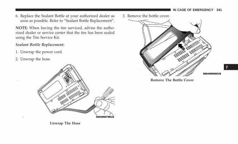
6. Replace the Sealant Bottle at your authorized dealer assoon as possible. Refer to “Sealant Bottle Replacement”.
NOTE: When having the tire serviced, advise the autho-rized dealer or service center that the tire has been sealedusing the Tire Service Kit.
Sealant Bottle Replacement:
1. Unwrap the power cord.
2. Unwrap the hose.
3. Remove the bottle cover.
Unwrap The Hose
Remove The Bottle Cover
7
IN CASE OF EMERGENCY 341
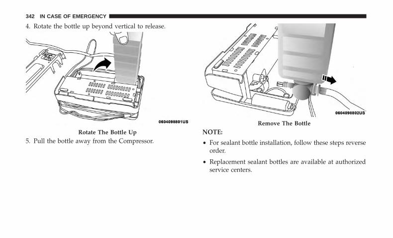
4. Rotate the bottle up beyond vertical to release.
5. Pull the bottle away from the Compressor.NOTE:
• For sealant bottle installation, follow these steps reverseorder.
• Replacement sealant bottles are available at authorizedservice centers.
Rotate The Bottle Up
Remove The Bottle
342 IN CASE OF EMERGENCY

JUMP STARTING
If your vehicle has a discharged battery, it can be jumpstarted using a set of jumper cables and a battery in anothervehicle or by using a portable battery booster pack. Jumpstarting can be dangerous if done improperly, so pleasefollow the procedures in this section carefully.
NOTE: When using a portable battery booster pack, followthe manufacturer’s operating instructions and precautions.
WARNING!
Do not attempt jump starting if the battery is frozen. Itcould rupture or explode and cause personal injury.
CAUTION!
Do not use a portable battery booster pack or any otherbooster source with a system voltage greater than 12Volts or damage to the battery, starter motor, alternatoror electrical system may occur.
Preparations For Jump Start
The battery in your vehicle is located in the front of theengine compartment, behind the left headlight assembly.
NOTE: The positive battery post is covered with a protec-tive cap. Lift up on the cap to gain access to the post.
Positive Battery Post
7
IN CASE OF EMERGENCY 343
WARNING!
• Take care to avoid the radiator cooling fan wheneverthe hood is raised. It can start anytime the ignitionswitch is ON. You can be injured by moving fanblades.
• Remove any metal jewelry such as rings, watchbands and bracelets that could make an inadvertentelectrical contact. You could be seriously injured.
• Batteries contain sulfuric acid that can burn yourskin or eyes and generate hydrogen gas which isflammable and explosive. Keep open flames orsparks away from the battery.
1. Apply the parking brake, shift the automatic transmis-sion into PARK (manual transmission in NEUTRAL)and turn the ignition to OFF/LOCK.
2. Turn off the heater, radio, and all unnecessary electricalaccessories.
3. If using another vehicle to jump start the battery, parkthe vehicle within the jumper cables reach, set theparking brake and make sure the ignition is OFF/LOCK.
WARNING!
Do not allow vehicles to touch each other as this couldestablish a ground connection and personal injurycould result.
Jump Starting Procedure
WARNING!
Failure to follow this jump starting procedure couldresult in personal injury or property damage due tobattery explosion.
CAUTION!
Failure to follow these procedures could result indamage to the charging system of the booster vehicleor the discharged vehicle.
Connecting The Jumper Cables
1. Connect the positive (+) end of the jumper cable to thepositive (+) post of the discharged vehicle.
2. Connect the opposite end of the positive (+) jumpercable to the positive (+) post of the booster battery.
344 IN CASE OF EMERGENCY
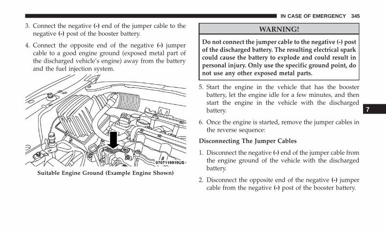
3. Connect the negative (-) end of the jumper cable to thenegative (-) post of the booster battery.
4. Connect the opposite end of the negative (-) jumpercable to a good engine ground (exposed metal part ofthe discharged vehicle’s engine) away from the batteryand the fuel injection system.
WARNING!
Do not connect the jumper cable to the negative (-) postof the discharged battery. The resulting electrical sparkcould cause the battery to explode and could result inpersonal injury. Only use the specific ground point, donot use any other exposed metal parts.
5. Start the engine in the vehicle that has the boosterbattery, let the engine idle for a few minutes, and thenstart the engine in the vehicle with the dischargedbattery.
6. Once the engine is started, remove the jumper cables inthe reverse sequence:
Disconnecting The Jumper Cables
1. Disconnect the negative (-) end of the jumper cable fromthe engine ground of the vehicle with the dischargedbattery.
2. Disconnect the opposite end of the negative (-) jumpercable from the negative (-) post of the booster battery.
Suitable Engine Ground (Example Engine Shown)
7
IN CASE OF EMERGENCY 345

3. Disconnect the positive (+) end of the jumper cable fromthe positive (+) post of the booster battery.
4. Disconnect the opposite end of the positive (+) jumpercable from the positive (+) post of the vehicle with thedischarged battery.
If frequent jump starting is required to start your vehicle,you should have the battery and charging system in-spected at your authorized dealer.
CAUTION!
Accessories plugged into the vehicle power outletsdraw power from the vehicle’s battery, even when notin use (i.e., cellular devices, etc.). Eventually, if pluggedin long enough without engine operation, the vehicle’sbattery will discharge sufficiently to degrade batterylife and/or prevent the engine from starting.
REFUELING IN EMERGENCY
The fuel filling procedure in case of emergency is describedin the “Emergency Gas Can Refueling”. Refer to “RefuelingThe Vehicle” in “Starting And Operating” for furtherinformation.
IF YOUR ENGINE OVERHEATS
In any of the following situations, you can reduce thepotential for overheating your engine by taking the appro-priate action.
• On the highways — slow down.
• In city traffic — while stopped, place the transmission inNEUTRAL, but do not increase engine idle speed.
CAUTION!
Driving with a hot cooling system could damage yourvehicle. If the temperature gauge reads “H,” pull overand stop the vehicle. Idle the vehicle with the airconditioner turned off until the pointer drops backinto the normal range. If the pointer remains on the“H” and you hear continuous chimes, turn the engineoff immediately and call for service.
NOTE: There are steps that you can take to slow down animpending overheat condition:
• If your air conditioner (A/C) is on, turn it off. The A/Csystem adds heat to the engine cooling system andturning the A/C off can help remove this heat.
346 IN CASE OF EMERGENCY

• You can also turn the temperature control to maximumheat, the mode control to floor and the blower control tohigh. This allows the heater core to act as a supplementto the radiator and aids in removing heat from theengine cooling system.
WARNING!
You or others can be badly burned by hot enginecoolant (antifreeze) or steam from your radiator. If yousee or hear steam coming from under the hood, do notopen the hood until the radiator has had time to cool.Never try to open a cooling system pressure cap whenthe radiator or coolant bottle is hot.
GEAR SELECTOR OVERRIDE
If a malfunction occurs, and the gear selector cannot bemoved out of the PARK position, you can use the followingprocedure to temporarily move the gear selector:
1. Turn the engine OFF.
2. Apply the park brake.
3. Grasp the boot material rearward of the gear selectorand pull up to carefully separate the gear selector bezeland boot assembly from the center console.
4. Press and maintain firm pressure on the brake pedal.
5. Insert a small screwdriver or similar tool down into thegear selector override access hole (at the right rearcorner of the gear selector assembly), and push and holdthe override release lever down.
Gear Selector Bezel
7
IN CASE OF EMERGENCY 347

6. Move the gear selector to the NEUTRAL position.
7. The vehicle may then be started in NEUTRAL.
8. Reinstall the gear selector boot.
FREEING A STUCK VEHICLE
If your vehicle becomes stuck in mud, sand or snow, it canoften be moved using a rocking motion. Turn the steeringwheel right and left to clear the area around the frontwheels. For vehicles with automatic transmission, pushand hold the lock button on the gear selector. Then shift
back and forth between DRIVE and REVERSE (for auto-matic transmission) or SECOND GEAR and REVERSE (formanual transmission) while gently pressing the accelerator.
NOTE: For vehicles with automatic transmission, shiftsbetween DRIVE and REVERSE can only be achieved atwheel speeds of 5 mph (8 km/h) or less. Whenever thetransmission remains in NEUTRAL for more than twoseconds, you must press the brake pedal to engage DRIVEor REVERSE.
Use the least amount of accelerator pedal pressure that willmaintain the rocking motion without spinning the wheelsor racing the engine.
WARNING!
Fast spinning tires can be dangerous. Forces generatedby excessive wheel speeds may cause damage, or evenfailure, of the axle and tires. A tire could explode andinjure someone. Do not spin your vehicle’s wheelsfaster than 30 mph (48 km/h) or for longer than 30seconds continuously without stopping when you arestuck and do not let anyone near a spinning wheel, nomatter what the speed.
Gear Selector Override Access Hole
348 IN CASE OF EMERGENCY

NOTE: Push the “ESC Off” switch (if necessary), to placethe Electronic Stability Control (ESC) system in “PartialOff” mode, before rocking the vehicle. Refer to “ElectronicBrake Control System” in “Safety” for further information.Once the vehicle has been freed, push the �ESC Off� switchagain to restore “ESC On” mode.
CAUTION!
• Racing the engine or spinning the wheels may leadto transmission overheating and failure. Allow theengine to idle with the transmission in NEUTRALfor at least one minute after every five rocking-motion cycles. This will minimize overheating andreduce the risk of clutch or transmission failureduring prolonged efforts to free a stuck vehicle.
(Continued)
CAUTION! (Continued)• When “rocking” a stuck vehicle by shifting between
DRIVE/SECOND gear and REVERSE, do not spinthe wheels faster than 15 mph (24 km/h), or drive-train damage may result.
• Revving the engine or spinning the wheels too fastmay lead to transmission overheating and failure. Itcan also damage the tires. Do not spin the wheelsabove 30 mph (48 km/h) while in gear (no transmis-sion shifting occurring).
TOWING A DISABLED VEHICLE
This section describes procedures for towing a disabledvehicle using a commercial towing service.
Towing Condition Wheels OFFThe Ground
FWD MODELS 4X4 MODELS
Flat Tow NONE NOT ALLOWED NOT ALLOWEDWheel Lift Or
Dolly TowRear NOT ALLOWED NOT ALLOWEDFront OK NOT ALLOWED
Flatbed ALL BEST METHOD ONLY METHOD
7
IN CASE OF EMERGENCY 349
Proper towing or lifting equipment is required to preventdamage to your vehicle. Use only tow bars and otherequipment designed for this purpose, following equipmentmanufacturer’s instructions. Use of safety chains is man-datory. Attach a tow bar or other towing devices to mainstructural members of the vehicle, not to bumpers orassociated brackets. State and local laws regarding vehiclesunder tow must be observed.
NOTE:
• You must ensure that the Auto Park Brake feature isdisabled before towing this vehicle to avoid inadvertentElectric Park Brake engagement. The Auto Park Brakefeature is enabled or disabled via the customer program-mable features in the Uconnect Settings.
• Vehicles with a discharged battery, or total electricalfailure when the electric park brake (EPB) is engaged,will need a wheel dolly or jack to raise the rear wheelsoff the ground when moving the vehicle onto a flatbed.
If you must use the accessories (wipers, defrosters, etc.)while being towed, the ignition must be in the ON/RUNmode.
Note that the Safehold feature will engage the Electric ParkBrake whenever the driver’s door is opened (if the batteryis connected, ignition is ON, transmission is not in PARK,and brake pedal is released). If you are towing this vehiclewith the ignition in the ON/RUN mode, you must manu-ally disable the Electric Park Brake each time the driver’sdoor is opened by pressing the brake pedal and thenreleasing the EPB.
If the vehicle’s battery is discharged, refer to “Gear SelectorOverride” in this section for instructions on shifting theautomatic transmission out of PARK so that the vehicle canbe moved.
CAUTION!
• Do not use sling-type equipment when towing. Ve-hicle damage may occur.
• When securing the vehicle to a flatbed truck, do notattach to front or rear suspension components. Dam-age to your vehicle may result from improper towing.
• Ensure that the Electric Park Brake is released, andremains released, while being towed.
350 IN CASE OF EMERGENCY
Without The Key Fob
Special care must be taken when the vehicle is towed withthe ignition in the LOCK/OFF mode. The only approvedmethod of towing without the key fob is with a flatbedtruck. Proper towing equipment is necessary to preventdamage to the vehicle.
Front-Wheel Drive (FWD) Models — With Key Fob
The manufacturer recommends towing your vehicle withall four wheels OFF the ground using a flatbed.
If flatbed equipment is not available, this vehicle must betowed with the front wheels OFF the ground (using atowing dolly, or wheel lift equipment with the front wheelsraised).
Ensure that the Electric Park Brake is released, and remainsreleased, while being towed. The Electric Park Brake doesnot need to be released if all four wheels are off the ground.
CAUTION!
Towing this vehicle in violation of the above require-ments can cause severe engine and/or transmissiondamage. Damage from improper towing is not coveredunder the New Vehicle Limited Warranty.
4x4 Models
The manufacturer requires towing with all four wheelsOFF the ground.
Acceptable methods are to tow the vehicle on a flatbed, orwith one end of the vehicle raised and the opposite end ona towing dolly.
CAUTION!
• Front or rear wheel lifts must not be used (if theremaining wheels are on the ground). Internal dam-age to the transmission or transfer case will occur ifa front or rear wheel lift is used when towing.
• Towing this vehicle in violation of the above require-ments can cause severe transmission and/or transfercase damage. Damage from improper towing is notcovered under the New Vehicle Limited Warranty.
7
IN CASE OF EMERGENCY 351

Emergency Tow Hooks — If Equipped
If your vehicle is equipped with tow hooks, there will beone in the rear and two mounted on the front of the vehicle.The rear hook will be located on the driver’s side of thevehicle.
NOTE: For off-road recovery, it is recommended to useboth of the front tow hooks to minimize the risk of damageto the vehicle.
Place the ignition in the ON/RUN position, and subse-quently in OFF/LOCK, without opening the door. Duringtowing, remember that not having the aid of the powerbrakes and the electromechanical power steering will re-quire greater force when applying the brakes and steeringof the vehicle.
WARNING!
• Do not use a chain for freeing a stuck vehicle. Chainsmay break, causing serious injury or death.
(Continued)
Front Tow Hooks Location
Rear Tow Hook Location
352 IN CASE OF EMERGENCY

WARNING! (Continued)• Stand clear of vehicles when pulling with tow hooks.
Tow straps may become disengaged, causing seriousinjury.
CAUTION!
Tow hooks are for emergency use only, to rescue avehicle stranded off road. Do not use tow hooks fortow truck hookup or highway towing. You coulddamage your vehicle.
ENHANCED ACCIDENT RESPONSE SYSTEM(EARS)
This vehicle is equipped with an Enhanced AccidentResponse System.
Please refer to “Occupant Restraint Systems” in “Safety”for further information on the Enhanced Accident Re-sponse System (EARS) function.
EVENT DATA RECORDER (EDR)
This vehicle is equipped with an Event Data Recorder(EDR). The main purpose of an EDR is to record data thatwill assist in understanding how a vehicle’s systems per-formed under certain crash or near crash-like situations,such as an air bag deployment or hitting a road obstacle.
Please refer to “Occupant Restraint Systems” in “Safety”for further information on the Event Data Recorder (EDR).
7
IN CASE OF EMERGENCY 353


SERVICING AND MAINTENANCE
CONTENTS� SCHEDULED SERVICING . . . . . . . . . . . . . . . . .357
▫ Maintenance Plan. . . . . . . . . . . . . . . . . . . . . . .357
� ENGINE COMPARTMENT . . . . . . . . . . . . . . . . .360
▫ 2.4L Engine . . . . . . . . . . . . . . . . . . . . . . . . . . .360
▫ Checking Oil Level . . . . . . . . . . . . . . . . . . . . .361
▫ Adding Washer Fluid . . . . . . . . . . . . . . . . . . .361
▫ Maintenance-Free Battery . . . . . . . . . . . . . . . . .362
� DEALER SERVICE . . . . . . . . . . . . . . . . . . . . . . .362
▫ Engine Oil . . . . . . . . . . . . . . . . . . . . . . . . . . .363
▫ Engine Oil Filter . . . . . . . . . . . . . . . . . . . . . . .364
▫ Engine Air Cleaner Filter . . . . . . . . . . . . . . . . .364
▫ Air Conditioner Maintenance . . . . . . . . . . . . . .365
▫ Body Lubrication . . . . . . . . . . . . . . . . . . . . . .366
▫ Wiper Blades . . . . . . . . . . . . . . . . . . . . . . . . .366
▫ Exhaust System . . . . . . . . . . . . . . . . . . . . . . . .369
▫ Cooling System . . . . . . . . . . . . . . . . . . . . . . . .371
▫ Brake System . . . . . . . . . . . . . . . . . . . . . . . . .375
▫ Manual Transmission — If Equipped . . . . . . . .376
▫ Automatic Transmission — If Equipped . . . . . .377
� RAISING THE VEHICLE . . . . . . . . . . . . . . . . . .378
� TIRES . . . . . . . . . . . . . . . . . . . . . . . . . . . . . . . .378
▫ Tire Safety Information . . . . . . . . . . . . . . . . . .378
▫ Tires — General Information . . . . . . . . . . . . . .387
▫ Tire Types . . . . . . . . . . . . . . . . . . . . . . . . . . . .393
▫ Spare Tires — If Equipped . . . . . . . . . . . . . . . .394
▫ Tire Chains (Traction Devices) . . . . . . . . . . . . .396
▫ Tire Rotation Recommendations . . . . . . . . . . . .397
8
� DEPARTMENT OF TRANSPORTATION UNIFORMTIRE QUALITY GRADES . . . . . . . . . . . . . . . . . .399
▫ Treadwear . . . . . . . . . . . . . . . . . . . . . . . . . . . .399
▫ Traction Grades . . . . . . . . . . . . . . . . . . . . . . . .399
▫ Temperature Grades . . . . . . . . . . . . . . . . . . . . .399
� STORING THE VEHICLE . . . . . . . . . . . . . . . . . .400
� BODYWORK . . . . . . . . . . . . . . . . . . . . . . . . . . .401
▫ Protection From Atmospheric Agents . . . . . . . .401
▫ Body And Underbody Maintenance . . . . . . . . . .401
▫ Preserving The Bodywork . . . . . . . . . . . . . . . . .403
� INTERIORS . . . . . . . . . . . . . . . . . . . . . . . . . . . .404
▫ Seats And Fabric Parts . . . . . . . . . . . . . . . . . . .404
▫ Plastic And Coated Parts. . . . . . . . . . . . . . . . . .405
▫ Leather Parts . . . . . . . . . . . . . . . . . . . . . . . . . .406
▫ Glass Surfaces . . . . . . . . . . . . . . . . . . . . . . . . .406
356 SERVICING AND MAINTENANCE

SCHEDULED SERVICING
Your vehicle is equipped with an automatic oil changeindicator system. The oil change indicator system will re-mind you that it is time to take your vehicle in for scheduledmaintenance.
Based on engine operation conditions, the oil change indica-tor message will illuminate in the instrument cluster. Thismeans that service is required for your vehicle. Operatingconditions such as frequent short-trips, trailer tow andextremely hot or cold ambient temperatures will influencewhen the “Change Oil” or “Oil Change Required” message isdisplayed. Severe Operating Conditions can cause thechange oil message to illuminate as early as 3,500 miles(5,600 km) since last reset. Have your vehicle serviced assoon as possible, within the next 500 miles (805 km).
Your authorized dealer will reset the oil change indicatormessage after completing the scheduled oil change. If a sched-uled oil change is performed by someone other than yourauthorized dealer, the message can be reset by referring to thesteps described under “Instrument Cluster Display” in “Get-ting To Know Your Instrument Panel” for further information.
NOTE: Under no circumstances should oil change intervalsexceed 10,000 miles (16,000 km), one year or 350 hours ofengine run time, whichever comes first. The 350 hours of
engine run or idle time is generally only a concern for fleetcustomers.
Severe Duty All Models
Change Engine Oil at 4,000 miles (6,500 km) or 350 hours ofengine run time if the vehicle is operated in a dusty and offroad environment or is operated predominately at idle oronly very low engine RPM’s. This type of vehicle use isconsidered Severe Duty.
NOTE: The Oil Change Indicator will not illuminate underthese conditions.
Once A Month Or Before A Long Trip:
• Check engine oil level.
• Check windshield washer fluid level.
• Check the tire inflation pressures and look for unusualwear or damage.
• Check the fluid levels of the coolant reservoir, and brakemaster cylinder reservoir, and fill as needed.
• Check function of all interior and exterior lights.
Maintenance Plan
Refer to the “Maintenance Plan” on the following page forthe required maintenance intervals.
8
SERVICING AND MAINTENANCE 357

Required Maintenance Intervals.
At Every Oil Change Interval As Indicated By OilChange Indicator System:
Change oil and filterRotate the tires
Rotate at the first sign of irregular wear, even if it oc-curs before the oil indicator system turns on
Inspect battery and clean and tighten terminals as required
At Every Oil Change Interval As Indicated By OilChange Indicator System:
Inspect brake pads, shoes, rotors, drums, and hosesInspect engine cooling system protection and hoses
Inspect exhaust systemInspect engine air filter if using in dusty or off-road
conditions
Mileage or time passed (whichever comes first)
20,0
00
30,0
00
40,0
00
50,0
00
60,0
00
70,0
00
80,0
00
90,0
00
100,
000
110,
000
120,
000
130,
000
140,
000
150,
000
Or Years: 2 3 4 5 6 7 8 9 10 11 12 13 14 15Or Kilometers:
32,0
00
48,0
00
64,0
00
80,0
00
96,0
00
112,
000
128,
000
144,
000
160,
000
176,
000
192,
000
208,
000
224,
000
240,
000
If using your vehicle in dusty or off-road conditions, in-spect the air cleaner filter, and replace if necessary. X X X X X X X
Inspect the brake linings, replace if necessary. X X X X X X XInspect the front suspension, tie rod ends and bootseals, replace if necessary. X X X X X X X
Inspect the CV joints. X X X X X X XInspect front accessory drive belt, tensioner, idler pul-ley, and replace if necessary. X
358 SERVICING AND MAINTENANCE

Mileage or time passed (whichever comes first)
20,0
00
30,0
00
40,0
00
50,0
00
60,0
00
70,0
00
80,0
00
90,0
00
100,
000
110,
000
120,
000
130,
000
140,
000
150,
000
Or Years: 2 3 4 5 6 7 8 9 10 11 12 13 14 15Or Kilometers:
32,0
00
48,0
00
64,0
00
80,0
00
96,0
00
112,
000
128,
000
144,
000
160,
000
176,
000
192,
000
208,
000
224,
000
240,
000
Replace engine air cleaner filter. X X XReplace air conditioning/cabin air filter. X X X X X X XReplace spark plugs.* XFlush and replace the engine coolant at 10 years or150,000 miles (240,000 km) whichever comes first. X X
Inspect and replace PCV valve if necessary. X
* The spark plug change interval is mileage based only,yearly intervals do not apply.
WARNING!
• You can be badly injured working on or around amotor vehicle. Do only service work for which youhave the knowledge and the right equipment. If youhave any doubt about your ability to perform a
(Continued)
WARNING! (Continued)service job, take your vehicle to a competent me-chanic.
• Failure to properly inspect and maintain your vehiclecould result in a component malfunction and effectvehicle handling and performance. This could causean accident.
8
SERVICING AND MAINTENANCE 359

ENGINE COMPARTMENT
2.4L Engine
1 — Engine Air Cleaner Filter 5 — Battery 9 — Engine Coolant Pressure Cap2 — Engine Oil Dipstick 6 — Power Distribution Center (Fuses) 10 — Engine Coolant Reservoir3 — Engine Oil Fill Cap 7 — Washer Fluid Reservoir4 — Brake Fluid Reservoir 8 — Battery
360 SERVICING AND MAINTENANCE

Checking Oil Level
To assure proper engine lubrication, the engine oil must bemaintained at the correct level. Check the oil level atregular intervals, such as once a month or before a longtrip. The best time to check the engine oil level is approxi-mately five minutes after a fully warmed engine is shut off.Do not check oil level before starting the engine after it hassat overnight. Checking engine oil level when the engine iscold will give you an incorrect reading.
Checking the oil while the vehicle is on level ground, andapproximately five minutes after a fully warmed engine isshut off, will improve the accuracy of the oil level readings.Maintain the oil level between the range markings on thedipstick. The safe range is indicated by a crosshatch zone.Adding 1 quart (0.9 Liters) of oil when the reading is at thelow end of the indicated range will result in the oil level atthe full end of the indicator range.
CAUTION!
• Overfilling or underfilling will cause oil aeration, orloss of oil pressure. This could damage your engine.
• Never use Non-Detergent Oil or Straight Mineral Oilin the engine or damage may result.
Adding Washer Fluid
The fluid reservoir is located in the front of the enginecompartment. Be sure to check the fluid level in thereservoir at regular intervals. Fill the reservoir with wind-shield washer solvent (not radiator antifreeze) and operatethe system for a few seconds to flush out the residualwasher fluid.
When refilling the washer fluid reservoir, take somewasher fluid, apply it to a cloth or towel, and wipe cleanthe wiper blades; this will help blade performance.
To prevent freeze-up of your windshield washer system incold weather, select a solution or mixture that meets orexceeds the temperature range of your climate. This ratinginformation can be found on most washer fluid containers.
WARNING!
Commercially available windshield washer solventsare flammable. They could ignite and burn you. Caremust be exercised when filling or working around thewasher solution.
8
SERVICING AND MAINTENANCE 361

Maintenance-Free Battery
Your vehicle is equipped with a maintenance-free battery.You will never have to add water, nor is periodic mainte-nance required.
WARNING!
• Battery fluid is a corrosive acid solution and canburn or even blind you. Do not allow battery fluid tocontact your eyes, skin, or clothing. Do not lean overa battery when attaching clamps. If acid splashes ineyes or on skin, flush the area immediately withlarge amounts of water. Refer to “Jump StartingProcedure” in “In Case Of Emergency” for furtherinformation.
• Battery gas is flammable and explosive. Keep flameor sparks away from the battery. Do not use a boosterbattery or any other booster source with an outputgreater than 12 Volts. Do not allow cable clamps totouch each other.
• Battery posts, terminals, and related accessories con-tain lead and lead compounds. Wash hands afterhandling.
CAUTION!
• It is essential when replacing the cables on thebattery that the positive cable is attached to thepositive post and the negative cable is attached to thenegative post. Battery posts are marked positive (+)and negative (-) and are identified on the batterycase. Cable clamps should be tight on the terminalposts and free of corrosion.
• If a “fast charger” is used while the battery is in thevehicle, disconnect both vehicle battery cables beforeconnecting the charger to the battery. Do not use a“fast charger” to provide starting voltage.
DEALER SERVICE
An authorized dealer has the qualified service personnel,special tools, and equipment to perform all service opera-tions in an expert manner. Service Manuals are availablewhich include detailed service information for your ve-hicle. Refer to these Service Manuals before attempting anyprocedure yourself.
NOTE: Intentional tampering with emissions control sys-tems may void your warranty and could result in civilpenalties being assessed against you.
362 SERVICING AND MAINTENANCE

WARNING!
You can be badly injured working on or around amotor vehicle. Only do service work for which youhave the knowledge and the proper equipment. If youhave any doubt about your ability to perform a servicejob, take your vehicle to a competent mechanic.
Engine Oil
Change Engine Oil
Refer to the “Scheduled Servicing” in this section for theproper maintenance intervals.
NOTE: Under no circumstances should oil change inter-vals exceed 10,000 miles (16,000 km), twelve months or350 hours of engine run time, whichever comes first. The350 hours of engine run or idle time is generally only aconcern for fleet customers.
Engine Oil Selection — 2.4L Engine
For best performance and maximum protection under alltypes of operating conditions, the manufacturer only rec-ommends engine oils that are API certified and meet therequirements of FCA Material Standard MS-6395.
American Petroleum Institute (API) Engine OilIdentification Symbol
This symbol means that the oil hasbeen certified by the American Pe-troleum Institute (API). The manu-facturer only recommends API Cer-tified engine oils.
This symbol certifies 0W-20, 5W-20,0W-30, 5W-30 and 10W-30 engineoils.
CAUTION!
Do not use chemical flushes in your engine oil as thechemicals can damage your engine. Such damage is notcovered by the New Vehicle Limited Warranty.
Engine Oil Viscosity (SAE Grade) — 2.4L Engine
Mopar SAE 0W-20 engine oil approved to FCA MaterialStandard MS-6395 or equivalent is recommended for alloperating temperatures. This engine oil improves lowtemperature starting and vehicle fuel economy.
8
SERVICING AND MAINTENANCE 363

The engine oil filler cap also shows the recommendedengine oil viscosity for your engine. For information onengine oil fill cap location, refer to “Engine Compartment”in this section.
Lubricants which do not have both the engine oil certifi-cation mark and the correct SAE viscosity grade numbershould not be used.
Synthetic Engine Oils
You may use synthetic engine oils provided the recom-mended oil quality requirements are met, and the recom-mended maintenance intervals for oil and filter changes arefollowed.
Synthetic engine oils which do not have both the engine oilcertification mark and the correct SAE viscosity gradenumber should not be used.
Materials Added To Engine Oil
The manufacturer strongly recommends against the addi-tion of any additives (other than leak detection dyes) to theengine oil. Engine oil is an engineered product and itsperformance may be impaired by supplemental additives.
Disposing Of Used Engine Oil And Oil Filters
Care should be taken in disposing of used engine oil andoil filters from your vehicle. Used oil and oil filters,indiscriminately discarded, can present a problem to theenvironment. Contact an authorized dealer, service stationor governmental agency for advice on how and where usedoil and oil filters can be safely discarded in your area.
Engine Oil Filter
The engine oil filter should be replaced with a new filter atevery engine oil change.
Engine Oil Filter Selection
This manufacturer’s engines have a full-flow type dispos-able oil filter. Use a filter of this type for replacement. Thequality of replacement filters varies considerably. Onlyhigh quality filters should be used to assure most efficientservice. Mopar engine oil filters are high quality oil filtersand are recommended.
Engine Air Cleaner Filter
Refer to the “Maintenance Plan” in this section for theproper maintenance intervals.
364 SERVICING AND MAINTENANCE

NOTE: Be sure to follow the “Severe Duty Conditions”maintenance interval if applicable.
WARNING!
The air induction system (air cleaner, hoses, etc.) canprovide a measure of protection in the case of enginebackfire. Do not remove the air induction system (aircleaner, hoses, etc.) unless such removal is necessaryfor repair or maintenance. Make sure that no one isnear the engine compartment before starting the ve-hicle with the air induction system (air cleaner, hoses,etc.) removed. Failure to do so can result in seriouspersonal injury.
Engine Air Cleaner Filter Selection
The quality of replacement engine air cleaner filters variesconsiderably. Only high quality filters should be used toassure most efficient service. Mopar engine air cleanerfilters are a high quality filter and are recommended.
Air Conditioner Maintenance
For best possible performance, your air conditioner shouldbe checked and serviced by an authorized dealer at thestart of each warm season. This service should include
cleaning of the condenser fins and a performance test.Drive belt tension should also be checked at this time.
WARNING!
• Use only refrigerants and compressor lubricants ap-proved by the manufacturer for your air conditioningsystem. Some unapproved refrigerants are flam-mable and can explode, injuring you. Other unap-proved refrigerants or lubricants can cause the sys-tem to fail, requiring costly repairs. Refer toWarranty Information Book, located in your owner’sinformation kit, for further warranty information.
• The air conditioning system contains refrigerant un-der high pressure. To avoid risk of personal injury ordamage to the system, adding refrigerant or anyrepair requiring lines to be disconnected should bedone by an experienced technician.
CAUTION!
Do not use chemical flushes in your air conditioningsystem as the chemicals can damage your air condition-ing components. Such damage is not covered by theNew Vehicle Limited Warranty.
8
SERVICING AND MAINTENANCE 365

Refrigerant Recovery And Recycling R-134a — IfEquipped
R-134a Air Conditioning Refrigerant is a hydrofluoro-carbon (HFC) that is an ozone-friendly substance. Themanufacturer recommends that air conditioning service beperformed by an authorized dealer or other service facili-ties using recovery and recycling equipment.
NOTE: Use only manufacturer approved A/C system PAGcompressor oil and refrigerants.
A/C Air Filter
See an authorized dealer for service.
Body Lubrication
Locks and all body pivot points, including such items asseat tracks, door hinge pivot points and rollers, liftgate,tailgate, decklid, sliding doors and hood hinges, should belubricated periodically with a lithium based grease, such asMopar Spray White Lube to assure quiet, easy operationand to protect against rust and wear. Prior to the applica-tion of any lubricant, the parts concerned should be wipedclean to remove dust and grit; after lubricating excess oiland grease should be removed. Particular attention shouldalso be given to hood latching components to ensure
proper function. When performing other underhood ser-vices, the hood latch, release mechanism and safety catchshould be cleaned and lubricated.
The external lock cylinders should be lubricated twice ayear, preferably in the Fall and Spring. Apply a smallamount of a high quality lubricant, such as Mopar LockCylinder Lubricant directly into the lock cylinder.
Wiper Blades
Clean the rubber edges of the wiper blades and thewindshield and rear window periodically with a sponge orsoft cloth and a mild nonabrasive cleaner. This will removeaccumulations of salt, waxes, or road film, and help reducestreaking and smearing.
Operation of the wipers on dry glass for long periods maycause deterioration of the wiper blades. Always use washerfluid when using the wipers to remove salt or dirt from adry windshield or rear window.
Avoid using the wiper blades to remove frost or ice fromthe windshield or rear window. Make sure that they are notfrozen to the glass before turning them on to avoiddamaging the blade. Keep the wiper blade out of contactwith petroleum products such as engine oil, gasoline, etc.
366 SERVICING AND MAINTENANCE

NOTE: Life expectancy of wiper blades varies dependingon geographical area and frequency of use. Poor perfor-mance of blades may be present with chattering, marks,water lines or wet spots. If any of these conditions arepresent, clean the wiper blades or replace as necessary.
Wiper Blade Removal/Installation
CAUTION!
Do not allow the wiper arm to spring back against theglass without the wiper blade in place or the glass maybe damaged.
1. Lift the wiper arm to raise the wiper blade off of theglass, until the wiper arm is in the full up position.
2. To disengage the wiper blade from the wiper arm, flipup the locking tab.
Windshield Wiper Arm
1 — Wiper2 — Locking Tab3 — Wiper Arm
8
SERVICING AND MAINTENANCE 367

3. Tilt the lower end of the wiper blade away from the armand use one finger push the release tab toward thewiper arm.
4. Slide the wiper blade down towards the base of thewiper arm.
5. With the wiper blade disengaged, remove the wiperblade from the wiper arm by holding the wiper armwith one hand and separating the wiper blade from thewiper arm with the other hand (move the wiper bladedown toward the base of the wiper arm and away fromthe J hook in the end of the wiper arm).
Wiper Locking Assembly
1 — Wiper2 — Locking Tab
Wiper Disengaging
1 — Locking Tab2 — Wiper3 — Release Tab
368 SERVICING AND MAINTENANCE

6. Gently lower the wiper arm onto the glass.
Installing The Front Wipers
1. Lift the wiper arm off of the glass, until the wiper arm isin the full up position.
2. Position the wiper blade under the hook on the tip of thewiper arm with the wiper locking tab open.
3. Insert the receiver bracket on the wiper assembly intothe hook on the tip of the arm through the opening inthe wiper blade under the locking tab.
4. Slide the wiper blade up into the hook on the wiper armuntil it is latched (engagement will be accompanied byan audible click). Fold down the latch release tab andsnap it into its locked position.
5. Gently lower the wiper blade onto the glass.
Exhaust System
The best protection against carbon monoxide entry into thevehicle body is a properly maintained engine exhaustsystem.
If you notice a change in the sound of the exhaust system;or if the exhaust fumes can be detected inside the vehicle;or when the underside or rear of the vehicle is damaged;have an authorized technician inspect the complete ex-haust system and adjacent body areas for broken, dam-aged, deteriorated, or mispositioned parts. Open seams orloose connections could permit exhaust fumes to seep intothe passenger compartment. In addition, have the exhaustsystem inspected each time the vehicle is raised for lubri-cation or oil change. Replace as required.
Removing Wiper From Wiper Arm
1 — Wiper2 — Locking Tab3 — Wiper Arm J Hook
8
SERVICING AND MAINTENANCE 369

WARNING!
• Exhaust gases can injure or kill. They contain carbonmonoxide (CO), which is colorless and odorless.Breathing it can make you unconscious and caneventually poison you. To avoid breathing CO, referto “Safety Tips” in “Safety” for further information.
• A hot exhaust system can start a fire if you park overmaterials that can burn. Such materials might begrass or leaves coming into contact with your exhaustsystem. Do not park or operate your vehicle in areaswhere your exhaust system can contact anything thatcan burn.
CAUTION!
• The catalytic converter requires the use of unleadedfuel only. Leaded gasoline will destroy the effective-ness of the catalyst as an emissions control deviceand may seriously reduce engine performance andcause serious damage to the engine.
• Damage to the catalytic converter can result if yourvehicle is not kept in proper operating condition. In
(Continued)
CAUTION! (Continued)the event of engine malfunction, particularly involv-ing engine misfire or other apparent loss of perfor-mance, have your vehicle serviced promptly. Contin-ued operation of your vehicle with a severemalfunction could cause the converter to overheat,resulting in possible damage to the converter andvehicle.
Under normal operating conditions, the catalytic converterwill not require maintenance. However, it is important tokeep the engine properly tuned to assure proper catalystoperation and prevent possible catalyst damage.
NOTE: Intentional tampering with emissions control sys-tems can result in civil penalties being assessed againstyou.
In unusual situations involving grossly malfunctioningengine operation, a scorching odor may suggest severe andabnormal catalyst overheating. If this occurs, stop thevehicle, turn off the engine and allow it to cool. Service,including a tune-up to manufacturer’s specifications,should be obtained immediately.
370 SERVICING AND MAINTENANCE
To minimize the possibility of catalytic converter damage:
• Do not interrupt the ignition when the transmission is ingear and the vehicle is in motion.
• Do not try to start the vehicle by pushing or towing thevehicle.
• Do not idle the engine with any ignition componentsdisconnected or removed, such as when diagnostictesting, or for prolonged periods during very rough idleor malfunctioning operating conditions.
Cooling System
WARNING!
• You or others can be badly burned by hot enginecoolant (antifreeze) or steam from your radiator. Ifyou see or hear steam coming from under the hood,do not open the hood until the radiator has had timeto cool. Never open a cooling system pressure capwhen the radiator or coolant bottle is hot.
• Keep hands, tools, clothing, and jewelry away fromthe radiator cooling fan when the hood is raised. The
(Continued)
WARNING! (Continued)fan starts automatically and may start at any time,whether the engine is running or not.
• When working near the radiator cooling fan, discon-nect the fan motor lead or turn the ignition to theOFF mode. The fan is temperature controlled and canstart at any time the ignition is in the ON mode.
Coolant Checks
Check engine coolant (antifreeze) protection every 12months (before the onset of freezing weather, where appli-cable). If the engine coolant (antifreeze) is dirty or rusty inappearance, the system should be drained, flushed andrefilled with fresh engine coolant (antifreeze). Check thefront of the A/C condenser for any accumulation of bugs,leaves, etc. If dirty, clean by gently spraying water from agarden hose vertically down the face of the condenser.
Cooling System — Drain, Flush And Refill
NOTE: Some vehicles require special tools to add coolantproperly. Failure to fill these systems properly could lead tosevere internal engine damage. If any coolant is needed tobe added to the system please contact an local authorizeddealer.
8
SERVICING AND MAINTENANCE 371

If the engine coolant (antifreeze) is dirty or contains visiblesediment, have an authorized dealer clean and flush withOAT coolant (antifreeze) (conforming to MS.90032).
Refer to the “Maintenance Plan” in this section for theproper maintenance intervals.
Selection Of Coolant
Refer to “Fluids And Lubricants” in “Technical Specifica-tions” for further information.
NOTE:
• Mixing of engine coolant (antifreeze) other than speci-fied Organic Additive Technology (OAT) engine coolant(antifreeze), may result in engine damage and maydecrease corrosion protection. Organic Additive Tech-nology (OAT) engine coolant is different and should notbe mixed with Hybrid Organic Additive Technology(HOAT) engine coolant (antifreeze) or any “globallycompatible” coolant (antifreeze). If a non-OAT enginecoolant (antifreeze) is introduced into the cooling systemin an emergency, the cooling system will need to bedrained, flushed, and refilled with fresh OAT coolant(conforming to MS.90032), by an authorized dealer assoon as possible.
• Do not use water alone or alcohol-based engine coolant(antifreeze) products. Do not use additional rust inhibi-tors or antirust products, as they may not be compatiblewith the radiator engine coolant and may plug theradiator.
• This vehicle has not been designed for use with propyl-ene glycol-based engine coolant (antifreeze). Use ofpropylene glycolbased engine coolant (antifreeze) is notrecommended.
• Some vehicles require special tools to add coolant prop-erly. Failure to fill these systems properly could lead tosevere internal engine damage. If any coolant is neededto be added to the system please contact your localauthorized dealer.
Adding Coolant
Your vehicle has been built with an improved enginecoolant (OAT coolant conforming to MS.90032) that allowsextended maintenance intervals. This engine coolant (anti-freeze) can be used up to ten years or 150,000 miles(240,000 km) before replacement. To prevent reducing thisextended maintenance period, it is important that you usethe same engine coolant (OAT coolant conforming toMS.90032) throughout the life of your vehicle.
372 SERVICING AND MAINTENANCE

Please review these recommendations for using OrganicAdditive Technology (OAT) engine coolant (antifreeze)that meets the requirements of FCA Material StandardMS.90032. When adding engine coolant (antifreeze):
• We recommend using Mopar Antifreeze/Coolant 10Year/150,000 Mile (240,000 km) Formula OAT (OrganicAdditive Technology) that meets the requirements ofFCA Material Standard MS.90032.
• Mix a minimum solution of 50% OAT engine coolantthat meets the requirements of FCA Material StandardMS.90032 and distilled water. Use higher concentrations(not to exceed 70%) if temperatures below −34°F (−37°C)are anticipated. Please contact an authorized dealer forassistance.
• Use only high purity water such as distilled or deionizedwater when mixing the water/engine coolant (anti-freeze) solution. The use of lower quality water willreduce the amount of corrosion protection in the enginecooling system.
NOTE:
• It is the owner’s responsibility to maintain the proper levelof protection against freezing according to the tempera-tures occurring in the area where the vehicle is operated.
• Some vehicles require special tools to add coolant prop-erly. Failure to fill these systems properly could lead tosevere internal engine damage. If any coolant is neededto be added to the system, please contact a local autho-rized dealer.
• Mixing engine coolant (antifreeze) types is not recom-mended and can result in cooling system damage. IfHOAT and OAT coolant are mixed in an emergency, havea authorized dealer drain, flush, and refill with OATcoolant (conforming to MS.90032) as soon as possible.
Cooling System Pressure Cap
The cap must be fully tightened to prevent loss of enginecoolant (antifreeze), and to ensure that engine coolant(antifreeze) will return to the radiator from the coolantexpansion bottle/recovery tank if so equipped.
The cap should be inspected and cleaned if there is anyaccumulation of foreign material on the sealing surfaces.
WARNING!
• Do not open hot engine cooling system. Never addengine coolant (antifreeze) when the engine is over-
(Continued)
8
SERVICING AND MAINTENANCE 373
WARNING! (Continued)heated. Do not loosen or remove the cap to cool anoverheated engine. Heat causes pressure to build upin the cooling system. To prevent scalding or injury,do not remove the pressure cap while the system ishot or under pressure.
• Do not use a pressure cap other than the one speci-fied for your vehicle. Personal injury or enginedamage may result.
Disposal Of Used Coolant
Used ethylene glycol-based coolant (antifreeze) is a regu-lated substance requiring proper disposal. Check with yourlocal authorities to determine the disposal rules for yourcommunity. To prevent ingestion by animals or children,do not store ethylene glycol-based coolant in open contain-ers or allow it to remain in puddles on the ground. Ifingested by a child or pet, seek emergency assistanceimmediately. Clean up any ground spills immediately.
Coolant Level
The coolant expansion bottle provides a quick visualmethod for determining that the coolant level is adequate.
With the engine off and cold, the level of the engine coolant(antifreeze) in the bottle should be between the “MIN” and“MAX” marks.
As long as the engine operating temperature is satisfactory,the coolant bottle need only be checked once a month.
When additional engine coolant (antifreeze) is needed tomaintain the proper level, it should be added to the coolantbottle. Do not overfill.
Points To Remember
NOTE: When the vehicle is stopped after a few miles/kilometers of operation, you may observe vapor comingfrom the front of the engine compartment. This is normallya result of moisture from rain, snow, or high humidityaccumulating on the radiator and being vaporized whenthe thermostat opens, allowing hot engine coolant (anti-freeze) to enter the radiator.
If an examination of your engine compartment shows noevidence of radiator or hose leaks, the vehicle may besafely driven. The vapor will soon dissipate.
• Do not overfill the coolant expansion bottle.
• Check the coolant freeze point in the radiator and in thecoolant expansion bottle. If engine coolant (antifreeze)
374 SERVICING AND MAINTENANCE

needs to be added, the contents of the coolant expansionbottle must also be protected against freezing.
• If frequent engine coolant (antifreeze) additions arerequired, the cooling system should be pressure testedfor leaks.
• Maintain engine coolant (antifreeze) concentration at aminimum of 50% OAT coolant (conforming toMS.90032) and distilled water for proper corrosion pro-tection of your engine which contains aluminum com-ponents.
• Make sure that the coolant expansion bottle overflowhoses are not kinked or obstructed.
• Keep the front of the radiator clean. If your vehicle isequipped with air conditioning, keep the front of thecondenser clean.
• Do not change the thermostat for Summer or Winteroperation. If replacement is ever necessary, install ONLYthe correct type thermostat. Other designs may result inunsatisfactory engine coolant (antifreeze) performance,poor gas mileage, and increased emissions.
Brake System
In order to assure brake system performance, all brakesystem components should be inspected periodically. Referto the “Maintenance Plan” in this section for the propermaintenance intervals.
WARNING!
Riding the brakes can lead to brake failure and possi-bly a collision. Driving with your foot resting or ridingon the brake pedal can result in abnormally high braketemperatures, excessive lining wear, and possiblebrake damage. You would not have your full brakingcapacity in an emergency.
Brake Master Cylinder
The fluid in the master cylinder should be checked whenperforming under hood services or immediately if the“Brake Warning Light” is illuminated.
Be sure to clean the top of the master cylinder area beforeremoving the cap. If necessary, add fluid to bring the fluidlevel up to the requirements described on the brake fluidreservoir. With disc brakes, fluid level can be expected tofall as the brake pads wear. Brake fluid level should be
8
SERVICING AND MAINTENANCE 375

checked when pads are replaced. However, low fluid levelmay be caused by a leak and a checkup may be needed.
Use only manufacturer’s recommended brake fluid. Referto “Fluids And Lubricants” in “Technical Specifications”for further information.
WARNING!
• Use only manufacturer’s recommended brake fluid.Refer to “Fluids And Lubricants” in “TechnicalSpecifications” for further information. Using thewrong type of brake fluid can severely damage yourbrake system and/or impair its performance. Theproper type of brake fluid for your vehicle is alsoidentified on the original factory installed hydraulicmaster cylinder reservoir.
• To avoid contamination from foreign matter or mois-ture, use only new brake fluid or fluid that has beenin a tightly closed container. Keep the master cylin-der reservoir cap secured at all times. Brake fluid ina open container absorbs moisture from the airresulting in a lower boiling point. This may cause it
(Continued)
WARNING! (Continued)to boil unexpectedly during hard or prolonged brak-ing, resulting in sudden brake failure. This couldresult in a collision.
• Overfilling the brake fluid reservoir can result inspilling brake fluid on hot engine parts, causing thebrake fluid to catch fire. Brake fluid can also damagepainted and vinyl surfaces, care should be taken toavoid its contact with these surfaces.
• Do not allow petroleum based fluid to contaminatethe brake fluid. Brake seal components could bedamaged, causing partial or complete brake failure.This could result in a collision.
Manual Transmission — If Equipped
Lubricant Selection
Use only the manufacturers recommended transmissionfluid. Refer to “Fluids And Lubricants” in “TechnicalSpecifications” for further information.
376 SERVICING AND MAINTENANCE
Fluid Level Check
Check the fluid level by removing the fill plug. The fluidlevel should be between the bottom of the fill hole and apoint not more than 3/16 inch (4.7 mm) below the bottomof the hole.
Add fluid, if necessary, to maintain the proper level.
Please see your authorized dealer for service.
Frequency Of Fluid Change
Under normal operating conditions, the fluid installed atthe factory will give satisfactory lubrication for the life ofthe vehicle. Fluid changes are not necessary unless lubri-cant has become contaminated with water.
NOTE: If contaminated with water, the fluid should bechanged immediately.
Automatic Transmission — If Equipped
Selection Of Lubricant
It is important to use the proper transmission fluid toensure optimum transmission performance and life. Useonly the manufacturer’s specified transmission fluid. Referto “Fluids And Lubricants” in “Technical Specifications”
for fluid specifications. It is important to maintain thetransmission fluid at the correct level using the recom-mended fluid.
NOTE: No chemical flushes should be used in any trans-mission; only the approved lubricant should be used.
CAUTION!
Using a transmission fluid other than the manufactur-er’s recommended fluid may cause deterioration intransmission shift quality and/or torque convertershudder. Refer to “Fluids And Lubricants” in “Techni-cal Specifications” for fluid specifications.
Special Additives
The manufacturer strongly recommends against using anyspecial additives in the transmission. Automatic Transmis-sion Fluid (ATF) is an engineered product and its perfor-mance may be impaired by supplemental additives. There-fore, do not add any fluid additives to the transmission.The only exception to this policy is the use of special dyesfor diagnosing fluid leaks in six-speed transmissions.Avoid using transmission sealers as they may adverselyaffect seals.
8
SERVICING AND MAINTENANCE 377

CAUTION!
Do not use chemical flushes in your transmission asthe chemicals can damage your transmission compo-nents. Such damage is not covered by the New VehicleLimited Warranty.
Fluid Level Check
The fluid level is preset at the factory and does not requireadjustment under normal operating conditions. Routinefluid level checks are not required; therefore the transmis-sion has no dipstick. An authorized dealer can check yourtransmission fluid level using special service tools. If younotice fluid leakage or transmission malfunction, visit anauthorized dealer immediately to have the transmissionfluid level checked. Operating the vehicle with an im-proper fluid level can cause severe transmission damage.
CAUTION!
If a transmission fluid leak occurs, visit an authorizeddealer immediately. Severe transmission damage mayoccur. An authorized dealer has the proper tools toadjust the fluid level accurately.
Fluid And Filter Changes
Under normal operating conditions, the fluid installed atthe factory will provide satisfactory lubrication for the lifeof the vehicle.
Routine fluid and filter changes are not required. However,change the fluid and filter if the fluid becomes contami-nated (with water, etc.), or if the transmission is disas-sembled for any reason.
RAISING THE VEHICLE
In the case where it is necessary to raise the vehicle, go toan authorized dealer or service station.
TIRES
Tire Safety Information
Tire safety information will cover aspects of the followinginformation: Tire Markings, Tire Identification Numbers,Tire Terminology and Definitions, Tire Pressures, and TireLoading.
378 SERVICING AND MAINTENANCE
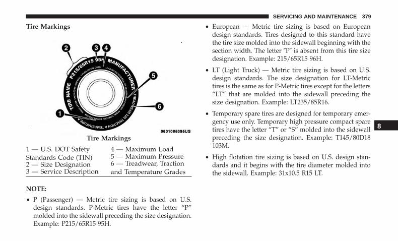
Tire Markings
NOTE:
• P (Passenger) — Metric tire sizing is based on U.S.design standards. P-Metric tires have the letter “P”molded into the sidewall preceding the size designation.Example: P215/65R15 95H.
• European — Metric tire sizing is based on Europeandesign standards. Tires designed to this standard havethe tire size molded into the sidewall beginning with thesection width. The letter �P� is absent from this tire sizedesignation. Example: 215/65R15 96H.
• LT (Light Truck) — Metric tire sizing is based on U.S.design standards. The size designation for LT-Metrictires is the same as for P-Metric tires except for the letters“LT” that are molded into the sidewall preceding thesize designation. Example: LT235/85R16.
• Temporary spare tires are designed for temporary emer-gency use only. Temporary high pressure compact sparetires have the letter “T” or “S” molded into the sidewallpreceding the size designation. Example: T145/80D18103M.
• High flotation tire sizing is based on U.S. design stan-dards and it begins with the tire diameter molded intothe sidewall. Example: 31x10.5 R15 LT.
Tire Markings
1 — U.S. DOT SafetyStandards Code (TIN)
4 — Maximum Load
2 — Size Designation5 — Maximum Pressure
3 — Service Description6 — Treadwear, Tractionand Temperature Grades
8
SERVICING AND MAINTENANCE 379

Tire Sizing Chart
EXAMPLE:Example Size Designation: P215/65R15XL 95H, 215/65R15 96H, LT235/85R16C, T145/80D18 103M, 31x10.5 R15 LTP = Passenger car tire size based on U.S. design standards, or�....blank....� = Passenger car tire based on European design standards, orLT = Light truck tire based on U.S. design standards, orT or S = Temporary spare tire or31 = Overall diameter in inches (in)215, 235, 145 = Section width in millimeters (mm)65, 85, 80 = Aspect ratio in percent (%)– Ratio of section height to section width of tire, or10.5 = Section width in inches (in)R = Construction code– �R� means radial construction, or– �D� means diagonal or bias construction15, 16, 18 = Rim diameter in inches (in)Service Description:95 = Load Index– A numerical code associated with the maximum load a tire can carry
380 SERVICING AND MAINTENANCE

EXAMPLE:H = Speed Symbol– A symbol indicating the range of speeds at which a tire can carry a load corresponding to its load index under cer-
tain operating conditions– The maximum speed corresponding to the speed symbol should only be achieved under specified operating condi-
tions (i.e., tire pressure, vehicle loading, road conditions, and posted speed limits)Load Identification:Absence of the following load identification symbols on the sidewall of the tire indicates a Standard Load (SL) tire:• XL = Extra load (or reinforced) tire, or• LL = Light load tire or• C, D, E, F, G = Load range associated with the maximum load a tire can carry at a specified pressureMaximum Load – Maximum load indicates the maximum load this tire is designed to carryMaximum Pressure – Maximum pressure indicates the maximum permissible cold tire inflation pressure for this tire
8
SERVICING AND MAINTENANCE 381

Tire Identification Number (TIN)
The TIN may be found on one or both sides of the tire;however, the date code may only be on one side. Tires withwhite sidewalls will have the full TIN, including the datecode, located on the white sidewall side of the tire. Look for
the TIN on the outboard side of black sidewall tires asmounted on the vehicle. If the TIN is not found on theoutboard side, then you will find it on the inboard side ofthe tire.
EXAMPLE:DOT MA L9 ABCD 0301
DOT = Department of Transportation– This symbol certifies that the tire is in compliance with the U.S. Department of Transportation tire safety standards
and is approved for highway useMA = Code representing the tire manufacturing location (two digits)L9 = Code representing the tire size (two digits)ABCD = Code used by the tire manufacturer (one to four digits)03 = Number representing the week in which the tire was manufactured (two digits)– 03 means the 3rd week01 = Number representing the year in which the tire was manufactured (two digits)– 01 means the year 2001– Prior to July 2000, tire manufacturers were only required to have one number to represent the year in which the
tire was manufactured. Example: 031 could represent the 3rd week of 1981 or 1991
382 SERVICING AND MAINTENANCE

Tire Terminology And Definitions
Term DefinitionB-Pillar The vehicle B-Pillar is the structural member of the body located be-
hind the front door.Cold Tire Inflation Pressure Cold tire inflation pressure is defined as the tire pressure after the
vehicle has not been driven for at least three hours, or driven lessthan 1 mile (1.6 km) after sitting for a minimum of three hours. In-flation pressure is measured in units of PSI (pounds per square inch)or kPa (kilopascals).
Maximum Inflation Pressure The maximum inflation pressure is the maximum permissible coldtire inflation pressure for this tire. The maximum inflation pressure ismolded into the sidewall.
Recommended Cold Tire Inflation Pressure Vehicle manufacturer’s recommended cold tire inflation pressure asshown on the tire placard.
Tire Placard A label permanently attached to the vehicle describing the vehicle’sloading capacity, the original equipment tire sizes and the recom-mended cold tire inflation pressures.
8
SERVICING AND MAINTENANCE 383

Tire Loading And Tire Pressure
NOTE: The proper cold tire inflation pressure is listed onthe driver’s side B-Pillar or the rear edge of the driver’sside door.
Check the inflation pressure of each tire, including thespare tire (if equipped), at least monthly and inflate to therecommended pressure for your vehicle.
Example Tire Placard Location (Door)
Example Tire Placard Location (B-Pillar)
384 SERVICING AND MAINTENANCE

Tire And Loading Information Placard
This placard tells you important information about the:
1. Number of people that can be carried in the vehicle.
2. Total weight your vehicle can carry.
3. Tire size designed for your vehicle.
4. Cold tire inflation pressures for the front, rear, and sparetires.
Loading
The vehicle maximum load on the tire must not exceed theload carrying capacity of the tire on your vehicle. You willnot exceed the tire’s load carrying capacity if you adhere tothe loading conditions, tire size, and cold tire inflationpressures specified on the Tire and Loading Informationplacard in “Vehicle Loading” in the “Starting And Operat-ing” section of this manual.
NOTE: Under a maximum loaded vehicle condition, grossaxle weight ratings (GAWRs) for the front and rear axlesmust not be exceeded.
For further information on GAWRs, vehicle loading, andtrailer towing, refer to “Vehicle Loading” in the “StartingAnd Operating” section of this manual.
To determine the maximum loading conditions of yourvehicle, locate the statement “The combined weight ofoccupants and cargo should never exceed XXX kg orXXX lbs” on the Tire and Loading Information placard. Thecombined weight of occupants, cargo/luggage and trailertongue weight (if applicable) should never exceed theweight referenced here.
Tire And Loading Information Placard8
SERVICING AND MAINTENANCE 385

Steps For Determining Correct Load Limit—
(1) Locate the statement “The combined weight ofoccupants and cargo should never exceed XXX kg orXXX lbs.” on your vehicle’s placard.
(2) Determine the combined weight of the driver andpassengers that will be riding in your vehicle.
(3) Subtract the combined weight of the driver andpassengers from XXX kg or XXX lbs.
(4) The resulting figure equals the available amount ofcargo and luggage load capacity. For example, if “XXX”amount equals 1400 lbs. and there will be five 150 lbpassengers in your vehicle, the amount of availablecargo and luggage load capacity is 650 lbs. (1400-750(5x150) = 650 lbs.)
(5) Determine the combined weight of luggage andcargo being loaded on the vehicle. That weight may notsafely exceed the available cargo and luggage loadcapacity calculated in Step 4.
(6) If your vehicle will be towing a trailer, load fromyour trailer will be transferred to your vehicle. Consult
this manual to determine how this reduces the availablecargo and luggage load capacity of your vehicle.
Metric Example For Load Limit
For example, if “XXX” amount equals 635 kg and there willbe five 68 kg passengers in your vehicle, the amount ofavailable cargo and luggage load capacity is 295 kg (635-340 (5x68) = 295 kg) as shown in step 4.
NOTE:
• If your vehicle will be towing a trailer, load from yourtrailer will be transferred to your vehicle. The followingtable shows examples on how to calculate total load,cargo/luggage, and towing capacities of your vehiclewith varying seating configurations and number andsize of occupants. This table is for illustration purposesonly and may not be accurate for the seating and loadcarry capacity of your vehicle.
• For the following example, the combined weight ofoccupants and cargo should never exceed 865 lbs(392 kg).
386 SERVICING AND MAINTENANCE

WARNING!
Overloading of your tires is dangerous. Overloadingcan cause tire failure, affect vehicle handling, andincrease your stopping distance. Use tires of the rec-ommended load capacity for your vehicle. Never over-load them.
Tires — General Information
Tire Pressure
Proper tire inflation pressure is essential to the safe andsatisfactory operation of your vehicle. Four primary areasare affected by improper tire pressure:
• Safety and Vehicle Stability
• Economy
8
SERVICING AND MAINTENANCE 387

• Tread Wear
• Ride Comfort
Safety
WARNING!
• Improperly inflated tires are dangerous and cancause collisions.
• Underinflation increases tire flexing and can resultin overheating and tire failure.
• Overinflation reduces a tire’s ability to cushionshock. Objects on the road and chuckholes can causedamage that result in tire failure.
• Overinflated or underinflated tires can affect vehiclehandling and can fail suddenly, resulting in loss ofvehicle control.
• Unequal tire pressures can cause steering problems.You could lose control of your vehicle.
• Unequal tire pressures from one side of the vehicleto the other can cause the vehicle to drift to the rightor left.
• Always drive with each tire inflated to the recom-mended cold tire inflation pressure.
Both under-inflation and over-inflation affect the stabilityof the vehicle and can produce a feeling of sluggishresponse or over responsiveness in the steering.
NOTE:
• Unequal tire pressures from side to side may causeerratic and unpredictable steering response.
• Unequal tire pressure from side to side may cause thevehicle to drift left or right.
Fuel Economy
Underinflated tires will increase tire rolling resistanceresulting in higher fuel consumption.
Tread Wear
Improper cold tire inflation pressures can cause abnormalwear patterns and reduced tread life, resulting in the needfor earlier tire replacement.
Ride Comfort And Vehicle Stability
Proper tire inflation contributes to a comfortable ride.Over-inflation produces a jarring and uncomfortable ride.
388 SERVICING AND MAINTENANCE

Tire Inflation Pressures
The proper cold tire inflation pressure is listed on thedriver’s side B-Pillar or rear edge of the driver’s side door.
At least once a month:
• Check and adjust tire pressure with a good qualitypocket-type pressure gauge. Do not make a visualjudgement when determining proper inflation. Tiresmay look properly inflated even when they are under-inflated.
• Inspect tires for signs of tire wear or visible damage.
CAUTION!
After inspecting or adjusting the tire pressure, alwaysreinstall the valve stem cap. This will prevent moistureand dirt from entering the valve stem, which coulddamage the valve stem.
Inflation pressures specified on the placard are always“cold tire inflation pressure”. Cold tire inflation pressure isdefined as the tire pressure after the vehicle has not beendriven for at least three hours, or driven less than 1 mile(1.6 km) after sitting for a minimum of three hours. The
cold tire inflation pressure must not exceed the maximuminflation pressure molded into the tire sidewall.
Check tire pressures more often if subject to a wide rangeof outdoor temperatures, as tire pressures vary with tem-perature changes.
Tire pressures change by approximately 1 psi (7 kPa) per12°F (7°C) of air temperature change. Keep this in mindwhen checking tire pressure inside a garage, especially inthe Winter.
Example: If garage temperature = 68°F (20°C) and theoutside temperature = 32°F (0°C) then the cold tire inflationpressure should be increased by 3 psi (21 kPa), whichequals 1 psi (7 kPa) for every 12°F (7°C) for this outsidetemperature condition.
Tire pressure may increase from 2 to 6 psi (13 to 40 kPa)during operation. DO NOT reduce this normal pressurebuild up or your tire pressure will be too low.
Tire Pressures For High Speed Operation
The manufacturer advocates driving at safe speeds andwithin posted speed limits. Where speed limits or condi-tions are such that the vehicle can be driven at high speeds,
8
SERVICING AND MAINTENANCE 389

maintaining correct tire inflation pressure is very impor-tant. Increased tire pressure and reduced vehicle loadingmay be required for high-speed vehicle operation. Refer toan authorized tire dealer or original equipment vehicledealer for recommended safe operating speeds, loadingand cold tire inflation pressures.
WARNING!
High speed driving with your vehicle under maximumload is dangerous. The added strain on your tires couldcause them to fail. You could have a serious collision.Do not drive a vehicle loaded to the maximum capacityat continuous speeds above 75 mph (120 km/h).
Radial Ply Tires
WARNING!
Combining radial ply tires with other types of tires onyour vehicle will cause your vehicle to handle poorly.The instability could cause a collision. Always useradial ply tires in sets of four. Never combine themwith other types of tires.
Tire Repair
If your tire becomes damaged, it may be repaired if it meetsthe following criteria:
• The tire has not been driven on when flat.
• The damage is only on the tread section of your tire(sidewall damage is not repairable).
• The puncture is no greater than a ¼ of an inch (6 mm).
Consult an authorized tire dealer for tire repairs andadditional information.
Damaged Run Flat tires, or Run Flat tires that haveexperienced a loss of pressure should be replaced immedi-ately with another Run Flat tire of identical size and servicedescription (Load Index and Speed Symbol).
Run Flat Tires — If Equipped
Run Flat tires allow you the capability to drive 50 miles(80 km) at 50 mph (80 km/h) after a rapid loss of inflationpressure. This rapid loss of inflation is referred to as theRun Flat mode. A Run Flat mode occurs when the tireinflation pressure is of/or below 14 psi (96 kPa). Once aRun Flat tire reaches the run flat mode it has limiteddriving capabilities and needs to be replaced immediately.A Run Flat tire is not repairable.
390 SERVICING AND MAINTENANCE
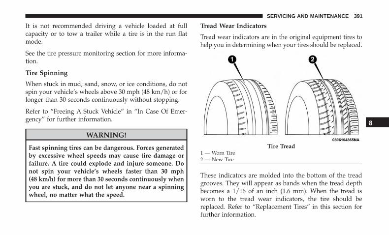
It is not recommended driving a vehicle loaded at fullcapacity or to tow a trailer while a tire is in the run flatmode.
See the tire pressure monitoring section for more informa-tion.
Tire Spinning
When stuck in mud, sand, snow, or ice conditions, do notspin your vehicle’s wheels above 30 mph (48 km/h) or forlonger than 30 seconds continuously without stopping.
Refer to “Freeing A Stuck Vehicle” in “In Case Of Emer-gency” for further information.
WARNING!
Fast spinning tires can be dangerous. Forces generatedby excessive wheel speeds may cause tire damage orfailure. A tire could explode and injure someone. Donot spin your vehicle’s wheels faster than 30 mph(48 km/h) for more than 30 seconds continuously whenyou are stuck, and do not let anyone near a spinningwheel, no matter what the speed.
Tread Wear Indicators
Tread wear indicators are in the original equipment tires tohelp you in determining when your tires should be replaced.
These indicators are molded into the bottom of the treadgrooves. They will appear as bands when the tread depthbecomes a 1/16 of an inch (1.6 mm). When the tread isworn to the tread wear indicators, the tire should bereplaced. Refer to “Replacement Tires” in this section forfurther information.
Tire Tread1 — Worn Tire2 — New Tire
8
SERVICING AND MAINTENANCE 391

Life Of Tire
The service life of a tire is dependent upon varying factorsincluding, but not limited to:
• Driving style.
• Tire pressure - Improper cold tire inflation pressures cancause uneven wear patterns to develop across the tiretread. These abnormal wear patterns will reduce treadlife, resulting in the need for earlier tire replacement.
• Distance driven.
• Performance tires, tires with a speed rating of V orhigher, and Summer tires typically have a reduced treadlife. Rotation of these tires per the vehicle scheduledmaintenance is highly recommended.
WARNING!
Tires and the spare tire should be replaced after sixyears, regardless of the remaining tread. Failure tofollow this warning can result in sudden tire failure.You could lose control and have a collision resulting inserious injury or death.
Keep dismounted tires in a cool, dry place with as littleexposure to light as possible. Protect tires from contact withoil, grease, and gasoline.
Replacement Tires
The tires on your new vehicle provide a balance of manycharacteristics. They should be inspected regularly forwear and correct cold tire inflation pressures. The manu-facturer strongly recommends that you use tires equivalentto the originals in size, quality and performance whenreplacement is needed. Refer to the paragraph on “TreadWear Indicators” in this section. Refer to the Tire andLoading Information placard or the Vehicle CertificationLabel for the size designation of your tire. The Load Indexand Speed Symbol for your tire will be found on theoriginal equipment tire sidewall.
See the Tire Sizing Chart example found in the “Tire SafetyInformation” section of this manual for more informationrelating to the Load Index and Speed Symbol of a tire.
It is recommended to replace the two front tires or two reartires as a pair. Replacing just one tire can seriously affectyour vehicle’s handling. If you ever replace a wheel, makesure that the wheel’s specifications match those of theoriginal wheels.
392 SERVICING AND MAINTENANCE

It is recommended you contact an authorized tire dealer ororiginal equipment dealer with any questions you mayhave on tire specifications or capability. Failure to useequivalent replacement tires may adversely affect thesafety, handling, and ride of your vehicle.
WARNING!
• Do not use a tire, wheel size, load rating, or speedrating other than that specified for your vehicle.Some combinations of unapproved tires and wheelsmay change suspension dimensions and perfor-mance characteristics, resulting in changes to steer-ing, handling, and braking of your vehicle. This cancause unpredictable handling and stress to steeringand suspension components. You could lose controland have a collision resulting in serious injury ordeath. Use only the tire and wheel sizes with loadratings approved for your vehicle.
• Never use a tire with a smaller load index or capacity,other than what was originally equipped on yourvehicle. Using a tire with a smaller load index couldresult in tire overloading and failure. You could losecontrol and have a collision.
(Continued)
WARNING! (Continued)• Failure to equip your vehicle with tires having ad-
equate speed capability can result in sudden tirefailure and loss of vehicle control.
CAUTION!
Replacing original tires with tires of a different sizemay result in false speedometer and odometer read-ings.
Tire Types
All Season Tires — If Equipped
All Season tires provide traction for all seasons (Spring,Summer, Fall, and Winter). Traction levels may vary be-tween different all season tires. All season tires can beidentified by the M+S, M&S, M/S or MS designation on thetire sidewall. Use all season tires only in sets of four; failureto do so may adversely affect the safety and handling ofyour vehicle.
Summer Or Three Season Tires — If Equipped
Summer tires provide traction in both wet and dry condi-tions, and are not intended to be driven in snow or on ice.
8
SERVICING AND MAINTENANCE 393
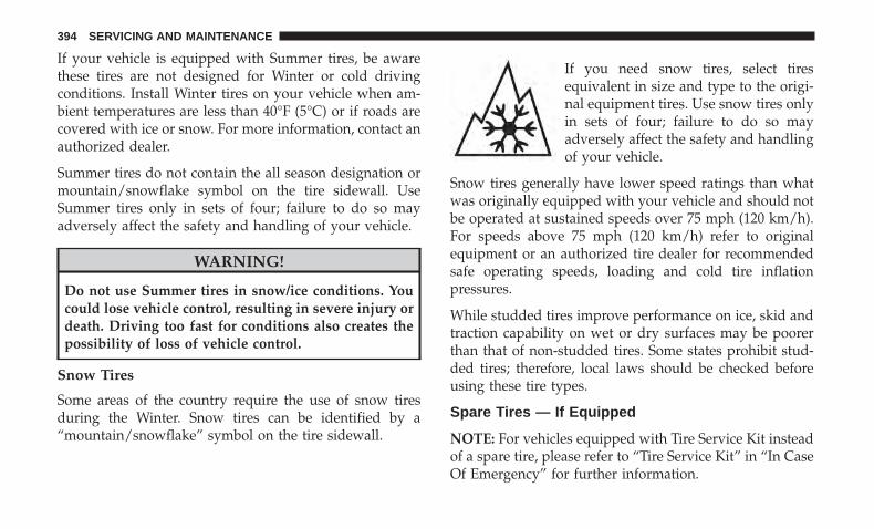
If your vehicle is equipped with Summer tires, be awarethese tires are not designed for Winter or cold drivingconditions. Install Winter tires on your vehicle when am-bient temperatures are less than 40°F (5°C) or if roads arecovered with ice or snow. For more information, contact anauthorized dealer.
Summer tires do not contain the all season designation ormountain/snowflake symbol on the tire sidewall. UseSummer tires only in sets of four; failure to do so mayadversely affect the safety and handling of your vehicle.
WARNING!
Do not use Summer tires in snow/ice conditions. Youcould lose vehicle control, resulting in severe injury ordeath. Driving too fast for conditions also creates thepossibility of loss of vehicle control.
Snow Tires
Some areas of the country require the use of snow tiresduring the Winter. Snow tires can be identified by a“mountain/snowflake” symbol on the tire sidewall.
If you need snow tires, select tiresequivalent in size and type to the origi-nal equipment tires. Use snow tires onlyin sets of four; failure to do so mayadversely affect the safety and handlingof your vehicle.
Snow tires generally have lower speed ratings than whatwas originally equipped with your vehicle and should notbe operated at sustained speeds over 75 mph (120 km/h).For speeds above 75 mph (120 km/h) refer to originalequipment or an authorized tire dealer for recommendedsafe operating speeds, loading and cold tire inflationpressures.
While studded tires improve performance on ice, skid andtraction capability on wet or dry surfaces may be poorerthan that of non-studded tires. Some states prohibit stud-ded tires; therefore, local laws should be checked beforeusing these tire types.
Spare Tires — If Equipped
NOTE: For vehicles equipped with Tire Service Kit insteadof a spare tire, please refer to “Tire Service Kit” in “In CaseOf Emergency” for further information.
394 SERVICING AND MAINTENANCE

CAUTION!
Because of the reduced ground clearance, do not takeyour vehicle through an automatic car wash with acompact or limited use temporary spare installed.Damage to the vehicle may result.
Spare Tire Matching Original Equipped Tire AndWheel — If Equipped
Your vehicle may be equipped with a spare tire and wheelequivalent in look and function to the original equipment tireand wheel found on the front or rear axle of your vehicle.This spare tire may be used in the tire rotation for yourvehicle. If your vehicle has this option, refer to an authorizedtire dealer for the recommended tire rotation pattern.
Compact Spare Tire — If Equipped
The compact spare is for temporary emergency use only. Youcan identify if your vehicle is equipped with a compact spareby looking at the spare tire description on the Tire andLoading Information Placard located on the driver’s sidedoor opening or on the sidewall of the tire. Compact sparetire descriptions begin with the letter “T” or “S” precedingthe size designation. Example: T145/80D18 103M.
T, S = Temporary Spare Tire
Since this tire has limited tread life, the original equipmenttire should be repaired (or replaced) and reinstalled onyour vehicle at the first opportunity.
Do not install a wheel cover or attempt to mount aconventional tire on the compact spare wheel, since thewheel is designed specifically for the compact spare tire.Do not install more than one compact spare tire and wheelon the vehicle at any given time.
WARNING!
Compact and collapsible spares are for temporaryemergency use only. With these spares, do not drivemore than 50 mph (80 km/h). Temporary use spareshave limited tread life. When the tread is worn to thetread wear indicators, the temporary use spare tireneeds to be replaced. Be sure to follow the warnings,which apply to your spare. Failure to do so could resultin spare tire failure and loss of vehicle control.
Full Size Spare — If Equipped
The full size spare is for temporary emergency use only.This tire may look like the originally equipped tire on thefront or rear axle of your vehicle, but it is not. This sparetire may have limited tread life. When the tread is worn to
8
SERVICING AND MAINTENANCE 395
the tread wear indicators, the temporary use full size sparetire needs to be replaced. Since it is not the same as youroriginal equipment tire, replace (or repair) the originalequipment tire and reinstall on the vehicle at the firstopportunity.
Limited Use Spare — If Equipped
The limited use spare tire is for temporary emergency useonly. This tire is identified by a label located on the limiteduse spare wheel. This label contains the driving limitationsfor this spare. This tire may look like the original equippedtire on the front or rear axle of your vehicle, but it is not.Installation of this limited use spare tire affects vehiclehandling. Since it is not the same as your original equip-ment tire, replace (or repair) the original equipment tireand reinstall on the vehicle at the first opportunity.
WARNING!
Limited use spares are for emergency use only. Instal-lation of this limited use spare tire affects vehiclehandling. With this tire, do not drive more than thespeed listed on the limited use spare wheel. Keepinflated to the cold tire inflation pressures listed on
(Continued)
WARNING! (Continued)your Tire and Loading Information Placard located onthe driver’s side B-Pillar or the rear edge of the driver’sside door. Replace (or repair) the original equipmenttire at the first opportunity and reinstall it on yourvehicle. Failure to do so could result in loss of vehiclecontrol.
Tire Chains (Traction Devices)
Use of traction devices require sufficient tire-to-body clear-ance. Follow these recommendations to guard againstdamage:
• Traction device must be of proper size for the tire, asrecommended by the traction device manufacturer.
• Install on front tires only.
• For a 215/65R16 tire, use of a snow traction device witha maximum projection of 7 mm beyond the tire profile isrecommended.
• No other tire sizes are recommended for use with a tirechain or traction device.
396 SERVICING AND MAINTENANCE

WARNING!
Using tires of different size and type (M+S, Snow)between front and rear axles can cause unpredictablehandling. You could lose control and have a collision.
CAUTION!
To avoid damage to your vehicle or tires, observe thefollowing precautions:• Because of restricted traction device clearance be-
tween tires and other suspension components, it isimportant that only traction devices in good condi-tion are used. Broken devices can cause seriousdamage. Stop the vehicle immediately if noise occursthat could indicate device breakage. Remove thedamaged parts of the device before further use.
• Install device as tightly as possible and then re-tighten after driving about ½ mile (0.8 km).
• Do not exceed 30 mph (48 km/h).• Drive cautiously and avoid severe turns and large
bumps, especially with a loaded vehicle.• Do not drive for a prolonged period on dry pave-
ment.
(Continued)
CAUTION! (Continued)• Observe the traction device manufacturer’s instruc-
tions on the method of installation, operating speed,and conditions for use. Always use the suggestedoperating speed of the device manufacturer’s if it isless than 30 mph (48 km/h).
• Do not use traction devices on a compact spare tire.
Tire Rotation Recommendations
The tires on the front and rear of your vehicle operate atdifferent loads and perform different steering, handling,and braking functions. For these reasons, they wear atunequal rates.
These effects can be reduced by timely rotation of tires. Thebenefits of rotation are especially worthwhile with aggres-sive tread designs such as those on On/Off Road type tires.Rotation will increase tread life, help to maintain mud,snow, and wet traction levels, and contribute to a smooth,quiet ride.
Refer to the “Maintenance Plan” for the proper mainte-nance intervals. The reasons for any rapid or unusual wearshould be corrected prior to rotation being performed.
8
SERVICING AND MAINTENANCE 397

The suggested Front Wheel Drive (FWD) rotation methodis the “forward cross” shown in the following diagram.This rotation pattern does not apply to some directionaltires that must not be reversed.
The suggested Four Wheel Drive (4WD) Tire rotationmethod is the “rearward cross” shown in the followingdiagram.
CAUTION!
Proper operation of four-wheel drive vehicles dependson tires of equal size, type and circumference on eachwheel. Any difference in tire size can cause damage tothe power transfer unit. Tire rotation schedule shouldbe followed to balance tire wear.
Front Wheel Drive (FWD) Tire Rotation
Four Wheel Drive (4WD) Tire Rotation
398 SERVICING AND MAINTENANCE
DEPARTMENT OF TRANSPORTATION UNIFORMTIRE QUALITY GRADES
The following tire grading categories were establishedby the National Highway Traffic Safety Administration.The specific grade rating assigned by the tire’s manu-facturer in each category is shown on the sidewall of thetires on your vehicle.
All passenger vehicle tires must conform to Federalsafety requirements in addition to these grades.
Treadwear
The Treadwear grade is a comparative rating, based onthe wear rate of the tire when tested under controlledconditions on a specified government test course. Forexample, a tire graded 150 would wear one and one-halftimes as well on the government course as a tire graded100. The relative performance of tires depends upon theactual conditions of their use, however, and may departsignificantly from the norm due to variations in drivinghabits, service practices, and differences in road charac-teristics and climate.
Traction Grades
The Traction grades, from highest to lowest, are AA, A,B, and C. These grades represent the tire’s ability to stop
on wet pavement, as measured under controlled condi-tions on specified government test surfaces of asphaltand concrete. A tire marked C may have poor tractionperformance.
WARNING!
The traction grade assigned to this tire is based onstraight-ahead braking traction tests, and does notinclude acceleration, cornering, hydroplaning, orpeak traction characteristics.
Temperature Grades
The Temperature grades are A (the highest), B, and C,representing the tire’s resistance to the generation ofheat and its ability to dissipate heat, when tested undercontrolled conditions on a specified indoor laboratorytest wheel.
Sustained high temperature can cause the material ofthe tire to degenerate and reduce tire life, and excessivetemperature can lead to sudden tire failure. The grade Ccorresponds to a level of performance, which all pas-senger vehicle tires must meet under the Federal MotorVehicle Safety Standard No. 109. Grades B and A
8
SERVICING AND MAINTENANCE 399
represent higher levels of performance on the laboratorytest wheel, than the minimum required by law.
WARNING!
The temperature grade for this tire is established fora tire that is properly inflated and not overloaded.Excessive speed, under-inflation, or excessive load-ing, either separately or in combination, can causeheat buildup and possible tire failure.
STORING THE VEHICLE
If the vehicle should remain stationary for more than amonth, observe the following precautions:
• Park your vehicle in a covered, dry and possibly airylocation the windows open slightly.
• Check that the Electric Park Brake is not engaged.
• Disconnect the negative (-) terminal from the batterypost and be sure that the battery is fully charged. Duringstorage check battery charge quarterly.
• If you do not disconnect the battery from the electricalsystem, check the battery charge every 30 days.
• Clean and protect the painted parts by applying protec-tive waxes.
• Clean and protect polished metal parts by applyingprotective waxes.
• Apply talcum powder to the front and rear wiper bladesand leave raised from the glass.
• Cover the vehicle with an appropriate cover taking carenot to damage the painted surface by dragging acrossdirty surfaces. Do not use plastic sheeting which will notallow the evaporation of moisture present on the surfaceof the vehicle.
• Inflate the tires at a pressure of +7.25 psi (+0.5 bar)higher than recommended on the tire placard and checkit periodically.
• Do not drain the engine cooling system.
• Whenever you leave the vehicle is stationary for twoweeks or more, run idle the engine for approximatelyfive minutes, with the air conditioning system on andhigh fan speed. This will ensure a proper lubrication ofthe system, thus minimizing the possibility of damage tothe compressor when the vehicle is put back into opera-tion.
400 SERVICING AND MAINTENANCE
NOTE: When the vehicle has not been started or driven forat least 30 days, an Extended Park Start Procedure isrequired to start the vehicle. Refer to “Starting The Engine”in “Starting And Operating” for further information.
CAUTION!
Before removal of the positive and negative terminalsto the battery, wait at least a minute with ignitionswitch in the OFF position and close the driver’s door.When reconnecting the positive and negative terminalsto the battery be sure the ignition switch is in the OFFposition and the driver’s door is closed.
BODYWORK
Protection From Atmospheric Agents
Vehicle body care requirements vary according to geographiclocations and usage. Chemicals that make roads passable insnow and ice and those that are sprayed on trees and roadsurfaces during other seasons are highly corrosive to themetal in your vehicle. Outside parking, which exposes yourvehicle to airborne contaminants, road surfaces on which thevehicle is operated, extreme hot or cold weather and otherextreme conditions will have an adverse effect on paint,metal trim, and underbody protection.
The following maintenance recommendations will enableyou to obtain maximum benefit from the corrosion resis-tance built into your vehicle.
What Causes Corrosion?
Corrosion is the result of deterioration or removal of paintand protective coatings from your vehicle.
The most common causes are:
• Road salt, dirt and moisture accumulation.
• Stone and gravel impact.
• Insects, tree sap and tar.
• Salt in the air near seacoast localities.
• Atmospheric fallout/industrial pollutants.
Body And Underbody Maintenance
Wheel And Wheel Trim Care
All wheels and wheel trim, especially aluminum andchrome plated wheels, should be cleaned regularly usingmild (neutral Ph) soap and water to maintain their lusterand to prevent corrosion. Wash wheels with the same soapsolution recommended for the body of the vehicle andremember to always wash when the surfaces are not hot tothe touch.
8
SERVICING AND MAINTENANCE 401

Your wheels are susceptible to deterioration caused by salt,sodium chloride, magnesium chloride, calcium chloride,etc., and other road chemicals used to melt ice or controldust on dirt roads. Use a soft cloth or sponge and mild soapto wipe away promptly. Do not use harsh chemicals or astiff brush. They can damage the wheel’s protective coatingthat helps keep them from corroding and tarnishing.
CAUTION!
Avoid products or automatic car washes that use acidicsolutions or strong alkaline additives or harsh brushes.Many aftermarket wheel cleaners and automatic carwashes may damage the wheel’s protective finish.Such damage is not covered by the New VehicleLimited Warranty. Only car wash soap, Mopar WheelCleaner or equivalent is recommended.
When cleaning extremely dirty wheels including excessivebrake dust, care must be taken in the selection of tire andwheel cleaning chemicals and equipment to prevent dam-age to the wheels. Mopar Wheel Treatment or MoparChrome Cleaner or their equivalent is recommended orselect a non-abrasive, non-acidic cleaner for aluminum orchrome wheels.
CAUTION!
Do not use scouring pads, steel wool, a bristle brush,metal polishes or oven cleaner. These products maydamage the wheel’s protective finish. Such damage isnot covered by the New Vehicle Limited Warranty.Only car wash soap, Mopar Wheel Cleaner or equiva-lent is recommended.
NOTE: If you intend parking or storing your vehicle for anextended period after cleaning the wheels with wheelcleaner, drive your vehicle and apply the brakes to removethe water droplets from the brake components. This activ-ity will remove the red rust on the brake rotors and preventvehicle vibration when braking.
Dark Vapor Chrome, Black Satin Chrome, or Low GlossClear Coat Wheels
CAUTION!
If your vehicle is equipped with these specialtywheels, DO NOT USE wheel cleaners, abrasives, orpolishing compounds. They will permanently damagethis finish and such damage is not covered by the New
(Continued)
402 SERVICING AND MAINTENANCE

CAUTION! (Continued)Vehicle Limited Warranty. HAND WASH ONLY US-ING MILD SOAP AND WATER WITH A SOFTCLOTH. Used on a regular basis; this is all that isrequired to maintain this finish.
Cleaning Headlights
Your vehicle is equipped with plastic headlights and foglights that are lighter and less susceptible to stone breakagethan glass headlights.
Plastic is not as scratch resistant as glass and thereforedifferent lens cleaning procedures must be followed.
To minimize the possibility of scratching the lenses andreducing light output, avoid wiping with a dry cloth. Toremove road dirt, wash with a mild soap solution followedby rinsing.
Do not use abrasive cleaning components, solvents, steelwool or other aggressive material to clean the lenses.
Preserving The Bodywork
Washing
• Wash your vehicle regularly. Always wash your vehiclein the shade using Mopar Car Wash, or a mild car washsoap, and rinse the panels completely with clear water.
• If insects, tar, or other similar deposits have accumulatedon your vehicle, use Mopar Super Kleen Bug and TarRemover to remove.
• Use a high quality cleaner wax, such as Mopar CleanerWax to remove road film, stains and to protect yourpaint finish. Take care never to scratch the paint.
• Avoid using abrasive compounds and power buffing thatmay diminish the gloss or thin out the paint finish.
CAUTION!
• Do not use abrasive or strong cleaning materials suchas steel wool or scouring powder that will scratchmetal and painted surfaces.
• Use of power washers exceeding 1,200 psi (8,274 kPa)can result in damage or removal of paint and decals.
8
SERVICING AND MAINTENANCE 403

Special Care
• If you drive on salted or dusty roads or if you drive nearthe ocean, hose off the undercarriage at least once amonth.
• It is important that the drain holes in the lower edges ofthe doors, rocker panels, and trunk be kept clear andopen.
• If you detect any stone chips or scratches in the paint,touch them up immediately. The cost of such repairs isconsidered the responsibility of the owner.
• If your vehicle is damaged due to a collision or similarcause that destroys the paint and protective coating,have your vehicle repaired as soon as possible. The costof such repairs is considered the responsibility of theowner.
• If you carry special cargo such as chemicals, fertilizers,de-icer salt, etc., be sure that such materials are wellpackaged and sealed.
• If a lot of driving is done on gravel roads, consider mudor stone shields behind each wheel.
• Use Mopar Touch Up Paint on scratches as soon aspossible. An authorized dealer has touch up paint tomatch the color of your vehicle.
INTERIORS
Seats And Fabric Parts
Use Mopar Total Clean to clean fabric upholstery andcarpeting.
WARNING!
Do not use volatile solvents for cleaning purposes.Many are potentially flammable, and if used in closedareas they may cause respiratory harm.
Stain Repel Fabric Cleaning Procedure — IfEquipped
Stain Repel seats may be cleaned in the following manner:
• Remove as much of the stain as possible by blotting witha clean, dry towel.
• Blot any remaining stain with a clean, damp towel.
• For tough stains, apply Mopar Total Clean, or a mildsoap solution to a clean, damp cloth and remove stain.Use a fresh, damp towel to remove soap residue.
• For grease stains, apply Mopar Multi-Purpose Cleanerto a clean, damp cloth and remove stain. Use a fresh,damp towel to remove soap residue.
404 SERVICING AND MAINTENANCE

• Do not use any harsh solvents or any other form ofprotectants on Stain Repel products.
Seat Belt Maintenance
Do not bleach, dye or clean the belts with chemical solventsor abrasive cleaners. This will weaken the fabric. Sundamage can also weaken the fabric.
If the belts need cleaning, use a mild soap solution orlukewarm water. Do not remove the belts from the vehicleto wash them. Dry with a soft cloth.
Replace the belts if they appear frayed or worn or if thebuckles do not work properly.
WARNING!
A frayed or torn belt could rip apart in a collision andleave you with no protection. Inspect the belt systemperiodically, checking for cuts, frays, or loose parts.Damaged parts must be replaced immediately. Do notdisassemble or modify the system. Seat belt assembliesmust be replaced after a collision if they have beendamaged (i.e., bent retractor, torn webbing, etc.).
Plastic And Coated Parts
Use Mopar Total Clean to clean vinyl upholstery.
CAUTION!
• Direct contact of air fresheners, insect repellents,suntan lotions, or hand sanitizers to the plastic,painted, or decorated surfaces of the interior maycause permanent damage. Wipe away immediately.
• Damage caused by these type of products may not becovered by your New Vehicle Limited Warranty.
Cleaning Plastic Instrument Cluster Lenses
The lenses in front of the instruments in this vehicle aremolded in clear plastic. When cleaning the lenses, caremust be taken to avoid scratching the plastic.
1. Clean with a wet soft cloth. A mild soap solution may beused, but do not use high alcohol content or abrasivecleaners. If soap is used, wipe clean with a clean dampcloth.
2. Dry with a soft cloth.
8
SERVICING AND MAINTENANCE 405

Leather Parts
Mopar Total Clean is specifically recommended for leatherupholstery.
Your leather upholstery can be best preserved by regularcleaning with a damp soft cloth. Small particles of dirt canact as an abrasive and damage the leather upholstery andshould be removed promptly with a damp cloth. Stubbornsoils can be removed easily with a soft cloth and MoparTotal Clean. Care should be taken to avoid soaking yourleather upholstery with any liquid. Please do not usepolishes, oils, cleaning fluids, solvents, detergents, orammonia-based cleaners to clean your leather upholstery.Application of a leather conditioner is not required tomaintain the original condition.
NOTE: If equipped with light colored leather, it tends toshow any foreign material, dirt, and fabric dye transfermore so than darker colors. The leather is designed for easycleaning, and FCA recommends Mopar total care leathercleaner applied on a cloth to clean the leather seats asneeded.
CAUTION!
Do not use Alcohol and Alcohol-based and/or Ketonebased cleaning products to clean leather seats, asdamage to the seat may result.
Glass Surfaces
All glass surfaces should be cleaned on a regular basis withMopar Glass Cleaner, or any commercial household-typeglass cleaner. Never use an abrasive type cleaner. Usecaution when cleaning the inside rear window equippedwith electric defrosters or windows equipped with radioantennas. Do not use scrapers or other sharp instrumentsthat may scratch the elements.
When cleaning the rear view mirror, spray cleaner on thetowel or cloth that you are using. Do not spray cleanerdirectly on the mirror.
406 SERVICING AND MAINTENANCE

TECHNICAL SPECIFICATIONS
CONTENTS� IDENTIFICATION DATA. . . . . . . . . . . . . . . . . . .408
▫ Vehicle Identification Number . . . . . . . . . . . . .408
� WHEEL AND TIRE TORQUE SPECIFICATIONS . .409
▫ Torque Specifications . . . . . . . . . . . . . . . . . . . .409
� FUEL REQUIREMENTS . . . . . . . . . . . . . . . . . . .410
▫ 2.4L Engine . . . . . . . . . . . . . . . . . . . . . . . . . . .410
▫ Reformulated Gasoline . . . . . . . . . . . . . . . . . . .411
▫ Gasoline/Oxygenate Blends . . . . . . . . . . . . . . .411
▫ E-85 Usage In Non-Flex Fuel Vehicles. . . . . . . . .411
▫ CNG And LP Fuel System Modifications . . . . . .412
▫ MMT In Gasoline . . . . . . . . . . . . . . . . . . . . . . .412
▫ Materials Added To Fuel . . . . . . . . . . . . . . . . .412
▫ Fuel System Cautions . . . . . . . . . . . . . . . . . . . .413
▫ Carbon Monoxide Warnings . . . . . . . . . . . . . . .413
� FLUID CAPACITIES . . . . . . . . . . . . . . . . . . . . . .414
� FLUIDS AND LUBRICANTS . . . . . . . . . . . . . . . .415
▫ Engine . . . . . . . . . . . . . . . . . . . . . . . . . . . . . .415
▫ Chassis . . . . . . . . . . . . . . . . . . . . . . . . . . . . .416
9

IDENTIFICATION DATA
Vehicle Identification Number
The Vehicle Identification Number (VIN) is found on theleft front corner of the windshield and is visible from theoutside of the vehicle. The VIN number also is stampedinto the right front body, on the front floor. With thepassenger seat in the rear most position, a door in thecarpet can be opened to reveal the VIN. It also appears onthe Automobile Information Disclosure Label affixed to awindow on your vehicle, the vehicle registration, and thetitle.
Vehicle Identification Number
Right Front Body VIN Location
408 TECHNICAL SPECIFICATIONS

NOTE: It is illegal to remove or alter the VIN.
WHEEL AND TIRE TORQUE SPECIFICATIONS
Proper lug nut/bolt torque is very important to ensure thatthe wheel is properly mounted to the vehicle. Any time awheel has been removed and reinstalled on the vehicle, thelug nuts/bolts should be torqued using a properly cali-brated torque wrench using a high quality six sided (hex)deep wall socket.
Torque Specifications
Lug Nut/BoltTorque
**Lug Nut/BoltSize
Lug Nut/BoltSocket Size
100 Ft-Lbs(135 N·m)
M12 x 1.25 19 mm
**Use only your authorized dealer recommended lug nuts/bolts and clean or remove any dirt or oil before tightening.
Inspect the wheel mounting surface prior to mounting thetire and remove any corrosion or loose particles.
Opening The VIN Door
Wheel Mounting Surface
9
TECHNICAL SPECIFICATIONS 409
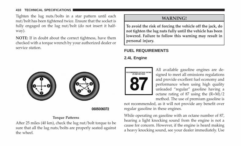
Tighten the lug nuts/bolts in a star pattern until eachnut/bolt has been tightened twice. Ensure that the socket isfully engaged on the lug nut/bolt (do not insert it half-way).
NOTE: If in doubt about the correct tightness, have themchecked with a torque wrench by your authorized dealer orservice station.
After 25 miles (40 km), check the lug nut/bolt torque to besure that all the lug nuts/bolts are properly seated againstthe wheel.
WARNING!
To avoid the risk of forcing the vehicle off the jack, donot tighten the lug nuts fully until the vehicle has beenlowered. Failure to follow this warning may result inpersonal injury.
FUEL REQUIREMENTS
2.4L Engine
All available gasoline engines are de-signed to meet all emissions regulationsand provide excellent fuel economy andperformance when using high qualityunleaded “regular” gasoline having aoctane rating of 87 using the (R+M)/2method. The use of premium gasoline is
not recommended, as it will not provide any benefit overregular gasoline in these engines.
While operating on gasoline with an octane number of 87,hearing a light knocking sound from the engine is not acause for concern. However, if the engine is heard makinga heavy knocking sound, see your dealer immediately. Use
Torque Patterns
410 TECHNICAL SPECIFICATIONS

of gasoline with an octane number lower than 87 can causeengine failure and may void or not be covered by the NewVehicle Limited Warranty.
Poor quality gasoline can cause problems such as hardstarting, stalling, and hesitations. If you experience thesesymptoms, try another brand of gasoline before consider-ing service for the vehicle.
Reformulated Gasoline
Many areas of the country require the use of cleanerburning gasoline referred to as “Reformulated Gasoline”.Reformulated gasoline contains oxygenates and are specifi-cally blended to reduce vehicle emissions and improve airquality.
The use of reformulated gasoline is recommended. Prop-erly blended reformulated gasoline will provide improvedperformance and durability of engine and fuel systemcomponents.
Gasoline/Oxygenate Blends
Some fuel suppliers blend unleaded gasoline with oxygen-ates such as ethanol.
CAUTION!
DO NOT use E-85, gasoline containing methanol, orgasoline containing more than 15% ethanol (E-15). Useof these blends may result in starting and drivabilityproblems, damage critical fuel system components,cause emissions to exceed the applicable standard,and/or cause the “Malfunction Indicator Light” toilluminate. Please observe pump labels as they shouldclearly communicate if a fuel contains greater than 15%ethanol (E-15).
Problems that result from using gasoline containing morethan 15% ethanol (E-15) or gasoline containing methanolare not the responsibility of the manufacturer and mayvoid or not be covered under New Vehicle Limited War-ranty.
E-85 Usage In Non-Flex Fuel Vehicles
Non-Flex Fuel Vehicles (FFV) are compatible with gasolinecontaining up to 15% ethanol (E-15). Gasoline with higherethanol content may void the New Vehicle Limited War-ranty.
9
TECHNICAL SPECIFICATIONS 411

If a Non-FFV vehicle is inadvertently fueled with E-85 fuel,the engine will have some or all of these symptoms:
• Operate in a lean mode.
• OBD II “Malfunction Indicator Light” on.
• Poor engine performance.
• Poor cold start and cold drivability.
• Increased risk for fuel system component corrosion.
CNG And LP Fuel System Modifications
Modifications that allow the engine to run on compressednatural gas (CNG) or liquid propane (LP) may result indamage to the engine, emissions, and fuel system compo-nents. Problems that result from running CNG or LP arenot the responsibility of the manufacturer and may void ornot be covered under the New Vehicle Limited Warranty.
MMT In Gasoline
Methylcyclopentadienyl Manganese Tricarbonyl (MMT) isa manganese-containing metallic additive that is blendedinto some gasoline to increase octane. Gasoline blendedwith MMT provides no performance advantage beyondgasoline of the same octane number without MMT. Gaso-line blended with MMT reduces spark plug life andreduces emissions system performance in some vehicles.
The manufacturer recommends that gasoline withoutMMT be used in your vehicle. The MMT content ofgasoline may not be indicated on the gasoline pump,therefore, you should ask your gasoline retailer whetherthe gasoline contains MMT. MMT is prohibited in Federaland California reformulated gasoline.
Materials Added To Fuel
Besides using unleaded gasoline with the proper octanerating, gasolines that contain detergents, corrosion, andstability additives are recommended. Using gasolines thathave these additives will help improve fuel economy,reduce emissions, and maintain vehicle performance.
Designated TOP TIER Detergent Gasolinecontains a higher level of detergents tofurther aide in minimizing engine and fuelsystem deposits. When available, the usageof Top Tier Detergent gasoline is recom-mended. Visit www.toptiergas.com for a listof TOP TIER Detergent Gasoline Retailers.
Indiscriminate use of fuel system cleaning agents should beavoided. Many of these materials intended for gum andvarnish removal may contain active solvents or similaringredients. These can harm fuel system gasket and dia-phragm materials.
412 TECHNICAL SPECIFICATIONS

Fuel System Cautions
CAUTION!
Follow these guidelines to maintain your vehicle’sperformance:• The use of leaded gasoline is prohibited by Federal
law. Using leaded gasoline can impair engine perfor-mance and damage the emissions control system.
• An out-of-tune engine or certain fuel or ignitionmalfunctions can cause the catalytic converter tooverheat. If you notice a pungent burning odor orsome light smoke, your engine may be out of tune ormalfunctioning and may require immediate service.Contact an authorized dealer for service assistance.
• The use of fuel additives, which are now being soldas octane enhancers, is not recommended. Most ofthese products contain high concentrations of metha-nol. Fuel system damage or vehicle performanceproblems resulting from the use of such fuels oradditives is not the responsibility of the manufac-turer and may void or not be covered under the NewVehicle Limited Warranty.
NOTE: Intentional tampering with the emissions control sys-tem can result in civil penalties being assessed against you.
Carbon Monoxide Warnings
WARNING!
Carbon monoxide (CO) in exhaust gases is deadly.Follow the precautions below to prevent carbon mon-oxide poisoning:• Do not inhale exhaust gases. They contain carbon
monoxide, a colorless and odorless gas, which cankill. Never run the engine in a closed area, such as agarage, and never sit in a parked vehicle with theengine running for an extended period. If the vehicleis stopped in an open area with the engine runningfor more than a short period, adjust the ventilationsystem to force fresh, outside air into the vehicle.
• Guard against carbon monoxide with proper main-tenance. Have the exhaust system inspected everytime the vehicle is raised. Have any abnormal condi-tions repaired promptly. Until repaired, drive withall side windows fully open.
9
TECHNICAL SPECIFICATIONS 413

FLUID CAPACITIES
U.S. MetricFuel (Approximate)2.4 Liter Gasoline Engine 13.5 Gallons 51 LitersEngine Oil With Filter2.4 Liter Gasoline Engine (SAE 0W-20, API Certified) 5.5 Quarts 5.2 LitersCooling System*2.4 Liter Gasoline Engine (Mopar Antifreeze/Engine Coolant 10Year/150,000 Mile Formula)
6.8 Quarts 6.5 Liters
* Includes heater and coolant recovery bottle filled to MAX level.
414 TECHNICAL SPECIFICATIONS

FLUIDS AND LUBRICANTS
Engine
Component Fluid, Lubricant, or Genuine PartEngine Coolant We recommend you use Mopar Antifreeze/Coolant 10 Year/150,000 Mile (240,000
Kilometers) Formula OAT (Organic Additive Technology) meeting the requirementsof FCA Material Standard MS.90032.
Engine Oil – 2.4 Liter Engine We recommend you use SAE 0W-20 API Certified Engine Oil, meeting the require-ments of FCA Material Standard MS-6395 such as Mopar, Pennzoil, and Shell Helix.Refer to your engine oil filler cap for correct SAE grade.
Engine Oil Filter We recommend you use a Mopar Engine Oil Filter.Spark Plugs We recommend you use Mopar Spark Plugs.Fuel Selection – 2.4 Liter Engine 87 Octane, 0-15% Ethanol 9
TECHNICAL SPECIFICATIONS 415

Chassis
Component Fluid, Lubricant, or Genuine PartManual Transmission – If Equipped We recommend you use Mopar C Series Manual & Dual Dry Clutch Transmis-
sion Fluid.Six-Speed Automatic Transmission(FWD Models) – If Equipped
Use only Mopar AW-1 Automatic Transmission Fluid, or equivalent. Failure touse the correct fluid may affect the function or performance of your transmis-sion.
Nine-Speed Automatic Transmission(4WD Models) – If Equipped
Use only Mopar ZF 8&9 Speed ATF Automatic Transmission Fluid, or equiva-lent. Failure to use the correct fluid may affect the function or performance ofyour transmission.
Power Transfer Unit (PTU) –If Equipped
We recommended you use Mopar Front Axle/PTU Synthetic Axle LubricantSAE 75W-90 (API GL-5).
Rear Differential (RDM) – If Equipped We recommended you use Mopar Rear Axle/RDM Synthetic Axle LubricantSAE 75W-90 (API GL-5).
Brake Master Cylinder We recommend you use Mopar DOT 3. If DOT 3 brake fluid is not available,then DOT 4 is acceptable.
Refrigerant Use Only Refrigerant R134aCharge Amounts:2.4L Engines — 567g (1.25lb)
Compressor Oil Use Only PAG Oil RL-8972.4L Engines — 135ml (4.56oz)
416 TECHNICAL SPECIFICATIONS

MULTIMEDIA
CONTENTS� UCONNECT SYSTEMS . . . . . . . . . . . . . . . . . . .419
� DRAG & DROP MENU BAR . . . . . . . . . . . . . . . .419
� CYBERSECURITY . . . . . . . . . . . . . . . . . . . . . . .420
� UCONNECT SETTINGS . . . . . . . . . . . . . . . . . . .422
▫ Customer Programmable Features —Uconnect 3 Settings . . . . . . . . . . . . . . . . . . . . .422
▫ Customer Programmable Features —Uconnect 4 Settings . . . . . . . . . . . . . . . . . . . . .438
▫ Customer Programmable Features —Uconnect 4/4C NAV Settings . . . . . . . . . . . . . .451
� STEERING WHEEL AUDIO CONTROLS . . . . . . .469
▫ Radio Operation. . . . . . . . . . . . . . . . . . . . . . . .469
▫ Media Mode . . . . . . . . . . . . . . . . . . . . . . . . . .469
� AUX/USB/MP3 CONTROL . . . . . . . . . . . . . . . .470
� RADIO OPERATION AND MOBILE PHONES . . .470
▫ Regulatory And Safety Information . . . . . . . . . .471
� UCONNECT VOICE RECOGNITIONQUICK TIPS . . . . . . . . . . . . . . . . . . . . . . . . . . .472
▫ Introducing Uconnect . . . . . . . . . . . . . . . . . . . .472
▫ Get Started . . . . . . . . . . . . . . . . . . . . . . . . . . .474
▫ Basic Voice Commands . . . . . . . . . . . . . . . . . . .475
▫ Radio . . . . . . . . . . . . . . . . . . . . . . . . . . . . . . .475
▫ Media . . . . . . . . . . . . . . . . . . . . . . . . . . . . . . .477
▫ Phone . . . . . . . . . . . . . . . . . . . . . . . . . . . . . . .479
▫ Voice Text Reply . . . . . . . . . . . . . . . . . . . . . . .481
▫ Climate . . . . . . . . . . . . . . . . . . . . . . . . . . . . . .482
▫ Navigation (4C NAV) . . . . . . . . . . . . . . . . . . . .483
▫ SiriusXM Guardian (4C/4C NAV)—If Equipped . . . . . . . . . . . . . . . . . . . . . . . . . . .484
▫ Register (4C/4C NAV) . . . . . . . . . . . . . . . . . . .484
10
▫ Vehicle Health Report/Alert (4C/4C NAV) . . . . .485
▫ Mobile App (4C/4C NAV) . . . . . . . . . . . . . . . .485
▫ SiriusXM Travel Link (4C NAV). . . . . . . . . . . . .486
▫ Siri Eyes Free — If Equipped . . . . . . . . . . . . . .486
▫ Using Do Not Disturb . . . . . . . . . . . . . . . . . . .487
▫ Android Auto — If Equipped . . . . . . . . . . . . . .488
▫ Apple CarPlay — If Equipped. . . . . . . . . . . . . .490
▫ General Information . . . . . . . . . . . . . . . . . . . . .491
▫ Additional Information . . . . . . . . . . . . . . . . . . .492
� CD MAINTENANCE . . . . . . . . . . . . . . . . . . . . .492
418 MULTIMEDIA

UCONNECT SYSTEMS
For detailed information about your Uconnect system orpairing a phone to your Uconnect system, refer to yourUconnect Owner’s Manual Supplement.
NOTE: Uconnect screen images are for illustration pur-poses only and may not reflect exact software for yourvehicle.
DRAG & DROP MENU BAR
The Uconnect features and services in the main menu barare easily changed for your convenience. Simply followthese steps: Uconnect 4 Apps Menu
10
MULTIMEDIA 419

1. Press the “Apps ” button to open the App screen.
2. Press and hold, then drag the selected App to replace anexisting shortcut in the main menu bar.
The new shortcut will now be an active App/shortcut onthe main menu bar.
CYBERSECURITY
Your vehicle may be a connected vehicle and may beequipped with both wired and wireless networks. Thesenetworks allow your vehicle to send and receive informa-tion. This information allows systems and features in yourvehicle to function properly.
Your vehicle may be equipped with certain security fea-tures to reduce the risk of unauthorized and unlawfulaccess to vehicle systems and wireless communications.Vehicle software technology continues to evolve over timeand FCA US LLC, working with its suppliers, evaluatesand takes appropriate steps as needed. Similar to a com-puter or other devices, your vehicle may require softwareupdates to improve the usability and performance of yoursystems or to reduce the potential risk of unauthorized andunlawful access to your vehicle systems.
The risk of unauthorized and unlawful access to yourvehicle systems may still exist, even if the most recentversion of vehicle software (such as Uconnect software) isinstalled.
Uconnect 4C/4C NAV Apps Menu
420 MULTIMEDIA
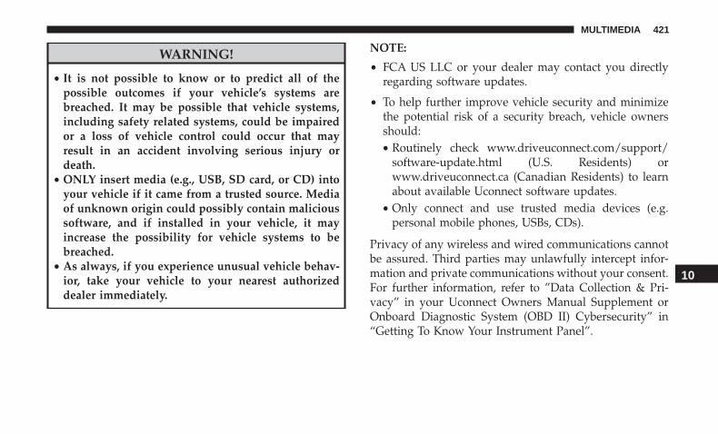
WARNING!
• It is not possible to know or to predict all of thepossible outcomes if your vehicle’s systems arebreached. It may be possible that vehicle systems,including safety related systems, could be impairedor a loss of vehicle control could occur that mayresult in an accident involving serious injury ordeath.
• ONLY insert media (e.g., USB, SD card, or CD) intoyour vehicle if it came from a trusted source. Mediaof unknown origin could possibly contain malicioussoftware, and if installed in your vehicle, it mayincrease the possibility for vehicle systems to bebreached.
• As always, if you experience unusual vehicle behav-ior, take your vehicle to your nearest authorizeddealer immediately.
NOTE:
• FCA US LLC or your dealer may contact you directlyregarding software updates.
• To help further improve vehicle security and minimizethe potential risk of a security breach, vehicle ownersshould:• Routinely check www.driveuconnect.com/support/
software-update.html (U.S. Residents) orwww.driveuconnect.ca (Canadian Residents) to learnabout available Uconnect software updates.
• Only connect and use trusted media devices (e.g.personal mobile phones, USBs, CDs).
Privacy of any wireless and wired communications cannotbe assured. Third parties may unlawfully intercept infor-mation and private communications without your consent.For further information, refer to ”Data Collection & Pri-vacy” in your Uconnect Owners Manual Supplement orOnboard Diagnostic System (OBD II) Cybersecurity” in“Getting To Know Your Instrument Panel”.
10
MULTIMEDIA 421

UCONNECT SETTINGS
The Uconnect system uses a combination of buttons on thetouchscreen and buttons on the faceplate located on thecenter of the instrument panel that allow you to access andchange the customer programmable features. Many fea-tures can vary by vehicle.
Buttons on the touchscreen are accessible on the Uconnecttouchscreen.
Buttons on the faceplate are located below, and beside theUconnect system in the center of the instrument panel. Inaddition, there is a Scroll/Enter control knob located on theright side. Turn the control knob to scroll through menusand change settings (i.e., 30, 60, 90), push the center of thecontrol knob one or more times to select or change a setting(i.e., ON, OFF).
Your Uconnect system may also have Display Off and backarrow buttons on the faceplate.
Push the Display Off button on the faceplate to turn off theUconnect screen. Push the Display Off button on thefaceplate a second time to turn the screen on.
Push the Back Arrow button on the faceplate to exit out ofa Menu or certain option on the Uconnect system.
Customer Programmable Features — Uconnect 3Settings
Push the “Settings” button on the touchscreen to displaythe settings menu screen. In this mode the Uconnectsystem allows you to access all of the available program-mable features.
Uconnect 3 With 5–inch Display Buttons On TheTouchscreen And Buttons On The Faceplate
1 — Uconnect Buttons On The Touchscreen2 — Uconnect Buttons On The Faceplate
422 MULTIMEDIA

NOTE: Only one touchscreen area may be selected at a time.
When making a selection, press the button on the touch-screen to enter the desired mode. Once in the desiredmode, press and release the preferred setting and makeyour selection. Once the setting is complete, either pressthe back arrow/Done button on the touchscreen or theBack button on the faceplate to return to the previousmenu. Pressing the Up or Down Arrow buttons on theright side of the screen will allow you to toggle up or downthrough the available settings.
NOTE: All settings should be changed with the ignition inthe “ON/RUN” position.
The following tables list the settings that may be foundwithin the Uconnect 3 radio, along with the selectableoptions pertaining to each setting.
Display
After pressing the “Display” button on the touchscreen, thefollowing settings will be available:
Setting Name Selectable OptionsDisplay Mode Auto Manual
Brightness + -
NOTE:The “Brightness” setting can also be adjusted by selecting any point on the scale between the “+” and “-” buttons onthe touchscreen.
Language English Français Español
NOTE:Selecting any option within the “Language” setting will change the language for all displayed nomenclature, includ-ing the trip functions and the navigation system (if equipped).
Touchscreen Beep Yes NoVoice Settings Voice Response Length Show Command List
10
MULTIMEDIA 423

Units
After pressing the “Units” button on the touchscreen, thefollowing settings will be available:
Setting Name Selectable OptionsUnits US Metric Custom
NOTE:• The “Metric” option changes the instrument cluster display to metric units of measure.• The “Custom” option allows setting the “Fuel Consumption” (L/100km, or km/L) and “Pressure” (kPa, or bar)
units of measure independently.
Clock & Date
After pressing the “Clock & Date” button on the touch-screen, the following settings will be available:
Setting Name Selectable OptionsSet Time and Format 12 hour 24 hour AM PM
NOTE:Within the “Set Time and Format” setting, press the corresponding arrow buttons on the touchscreen to adjust to thecorrect time.
Set Time Hours + –Set Time Minutes + –
424 MULTIMEDIA

Setting Name Selectable OptionsSet Date Up Arrow Down Arrow
NOTE:Within the “Set Date” setting, press the corresponding arrow buttons on the touchscreen to adjust to the correct date.
Show Time Status — IfEquipped
On Off
Sync Time — If Equipped On Off
Safety/Assistance
After pressing the “Safety/Assistance” button on thetouchscreen, the following settings will be available:
Setting Name Selectable OptionsParkView Backup Camera
DelayOn Off
NOTE:The “ParkView Backup Camera Delay” setting determines whether or not the screen will display the rear view imagewith dynamic grid lines for up to ten seconds after the vehicle is shifted out of REVERSE. This delay will be canceledif the vehicle’s speed exceeds 8 mph (13 km/h), the transmission is shifted into PARK, or the ignition is switched tothe OFF position.
10
MULTIMEDIA 425

Setting Name Selectable OptionsParkView Backup Camera
Active Guide LinesOn Off
NOTE:The “ParkView Backup Camera Active Guide Lines” setting overlays the Rear Backup Camera image with active, ordynamic, grid lines to help illustrate the width of the vehicle and its project back up path, based on the steeringwheel position when the option is checked. A dashed center line overlay indicates the center of the vehicle to assistwith parking or aligning to a hitch/receiver.
Forward Collision WarningPlus (FCW+) Sensitivity — If
Equipped
Far Med Near
NOTE:The “Forward Collision Warning Plus (FCW+) Sensitivity” setting determines at what relative distance the vehicledirectly in front of you needs to be at, before the system will warn you of a possible collision with the vehicle directlyin front of you, based on the option is selected. “Far” will give you the most amount of reaction time, whereas“Near” will give you the least amount of reaction time, based on the distance between the two vehicles.
426 MULTIMEDIA
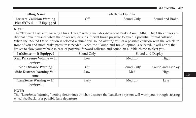
Setting Name Selectable OptionsForward Collision Warning
Plus (FCW+) — If EquippedOff Sound Only Sound and Brake
NOTE:The “Forward Collision Warning Plus (FCW+)” setting includes Advanced Brake Assist (ABA). The ABA applies ad-ditional brake pressure when the driver requests insufficient brake pressure to avoid a potential frontal collision.When the “Sound Only” option is selected a chime will sound alerting you of a possible collision with the vehicle infront of you and more brake pressure is needed. When the “Sound and Brake” option is selected, it will apply thebrakes to slow your vehicle in case of potential forward collision and sound an audible chime to alert you.
ParkSense — If Equipped Sound Only Sound and DisplayRear ParkSense Volume — If
EquippedLow Medium High
Side Distance Warning Off Sound Only Sound and DisplaySide Distance Warning Vol-
umeLow Med High
LaneSense Warning — IfEquipped
Early Medium Late
NOTE:The “LaneSense Warning” setting determines at what distance the LaneSense system will warn you, through steeringwheel feedback, of a possible lane departure.
10
MULTIMEDIA 427

Setting Name Selectable OptionsLaneSense Strength — If
EquippedLow Medium High
Blind Spot Alert — IfEquipped
Off Lights Lights and Chime
NOTE:If your vehicle has experienced any damage in the area where the sensor is located, even if the fascia is not damaged,the sensor may have become misaligned. Take your vehicle to an authorized dealer to verify sensor alignment. A sen-sor that is misaligned will result in the Blind Spot Monitor (BSM) not operating to specification.Rain Sensing Auto Wipers —
If EquippedOn Off
Electric Park Brake ServiceMode
Yes No
NOTE:The “Electric Park Brake Service Mode” feature provides a means for a technician or vehicle owner to utilize a vehicleintegrated, menu driven system, to command the electric park brake retraction, to service the rear foundation brakes(brake pads, calipers, rotors, etc.).
428 MULTIMEDIA

Brakes — If Equipped
After pressing the “Brakes” button on the touchscreen thefollowing setting will be available:
Setting Name Selectable OptionsAuto Park Brake On Off
Lights
After pressing the “Lights” button on the touchscreen, thefollowing settings will be available:
Setting Name Selectable OptionsHeadlight Sensitivity — If
EquippedLevel 1: minimum
sensitivityLevel 2: medium sen-
sitivityLevel 3: maximum sensitivity
NOTE:The greater the sensitivity set, the less the external light variation required to turn on the lights (e.g. with a setting onlevel 3 at sunset the headlights turn on earlier than in levels 1 and 2).
Headlight Off Delay 0 sec 30 sec 60 sec 90 sec
NOTE:When the “Headlight Off Delay” feature is selected, it allows the adjustment of the amount of time the headlightsremain on after the engine is shut off.
Greeting Lights On Off
10
MULTIMEDIA 429

Setting Name Selectable OptionsAutomatic High Beam Head-
lamps — If EquippedOn Off
Daytime Running Lights On OffCornering Lights On Off
NOTE:When the “Cornering Lights” feature is selected, if the steering wheel rotation angle is large or the turn signal indica-tors are on, a light (incorporated in the fog light) will turn on, on the relevant side to improve visibility at night.Flash Lights With Lock — If
EquippedOn Off
Interior Ambient Lights + -
NOTE:The “Interior Ambient Lights” setting can also be adjusted by selecting any point on the scale between the “+” and“-” buttons on the touchscreen.
430 MULTIMEDIA

Doors & Locks
After pressing the “Doors & Locks” button on the touch-screen, the following settings will be available:
Setting Name Selectable OptionsAuto Unlock On Exit On Off
NOTE:When this feature is selected, all doors will unlock when the vehicle is stopped and the transmission is in the PARKor NEUTRAL position and the driver’s door is opened.
Flash Lights With Lock On OffHorn With Lock On Off
Horn With Remote Start — IfEquipped
On Off
Remote Door Unlock/Door Unlock Driver All
NOTE:When “Driver” is selected, only the driver’s door will unlock on the first push of the key fob unlock button, you mustpush the key fob unlock button twice to unlock the passenger’s doors. When “All” is selected, all of the doors will unlockon the first press of the key fob unlock button. If “All” is programmed, all doors will unlock no matter which PassiveEntry equipped door handle is grasped. If “Driver” is programmed, only the driver’s door will unlock when the driver’sdoor is grasped. Touching the handle more than once will only result in the driver’s door opening once. If the driver’sdoor is opened, the interior door lock/unlock switch can be used to unlock all doors (or use key fob).
10
MULTIMEDIA 431

Setting Name Selectable OptionsMemory Linked To FOB — If
EquippedOn Off
NOTE:This feature provides automatic recall of all settings stored to a memory location (driver’s seat, exterior mirrors, steer-ing column position and radio station pre-sets) to enhance driver mobility when entering and exiting the vehicle.
Setting Name Selectable OptionsAuto Door Locks On Off
NOTE:When this feature is selected, all doors will lock automatically when the vehicle reaches a speed of 12 mph (20 km/h).
Auto Comfort Systems — If Equipped
After pressing the “Auto-On Comfort Systems” button onthe touchscreen, the following settings will be available:
Setting Name Selectable OptionsAuto-On Driver Heated/Ventilated Seat & Steering
Wheel With Vehicle Start — If EquippedOff Remote Start All Starts
NOTE:When this feature is selected, the driver’s heated seat and heated steering wheel will automatically turn on when tem-peratures are below 40° F (4.4° C). When temperatures are above 80° F (26.7° C), the driver vented seat will turn on.
432 MULTIMEDIA

Engine Off Options
After pressing the “Engine Off Options” button on thetouchscreen, the following settings will be available:
Setting Name Selectable OptionsHeadlight Off Delay 0 sec 30 sec 60 sec 90 sec
NOTE:When this feature is selected, it allows the adjustment of the amount of time the headlights remain on after the en-gine is shut off.
Radio Off Delay 0 min 20 min
NOTE:When this feature is selected, the radio will stay on for a preset time after the ignition key is turned to STOP/OFF.
Audio
After pressing the “Audio” button on the touchscreen, thefollowing settings will be available:
Setting Name Selectable OptionsEqualizer Bass Mid Treble
NOTE:When in this display you may adjust the “Bass”, “Mid”, and “Treble” settings. Adjust the settings with the “+” and“–” setting buttons on the touchscreen or by selecting any point on the scale between the “+” and “–” buttons on thetouchscreen. Bass/Mid/Treble also allow you to simply slide your finger up or down to change the setting as well aspress directly on the desired setting.
10
MULTIMEDIA 433

Setting Name Selectable OptionsBalance/Fade Up Arrow
ButtonDown Ar-
row ButtonLeft Arrow
ButtonRight Ar-
row ButtonCenter “C”
Button
NOTE:When in this display you may adjust the “Balance/Fade” of the audio by using the “Arrow” button on the touch-screen to adjust the sound level from the front and rear or right and left side speakers. Press the “Center ‘C’ Button”on the touchscreen to reset the balance and fade to the factory setting.
Speed Adjusted Volume Off 1 2 3Surround Sound — If Equipped On Off
Loudness On Off
NOTE:The “Loudness” feature improves sound quality at lower volumes when enabled.
AUX Volume Offset — If Equipped + -
NOTE:The “AUX Volume Offset” feature provides the ability to tune the audio level for portable devices connected throughthe AUX input.
434 MULTIMEDIA

Phone/Bluetooth
After pressing the “Phone/Bluetooth” button on the touch-screen, the following settings will be available:
Setting Name Selectable OptionsPaired Phones List of Paired Phones
NOTE:This feature shows which phones are paired to the Phone/Bluetooth system. For further information, refer to theUconnect Owner’s Manual Supplement.
SiriusXM Setup — If Equipped
After pressing the “SiriusXM Setup” button on the touch-screen, the following settings will be available:
Setting Name Selectable OptionsChannel Skip List of Channels
NOTE:SiriusXM can be programmed to designate a group of channels that are the most desirable to listen to or to excludeundesirable channels while scanning. This feature allows you to select the channels you would like to skip.
10
MULTIMEDIA 435

Setting Name Selectable OptionsSubscription Info Sirius ID
NOTE:New vehicle purchasers or lessees will receive a free limited time subscription to SiriusXM Satellite Radio with yourradio. Following the expiration of the free services, it will be necessary to access the information on the SubscriptionInformation screen to re-subscribe.
1. Press the “Subscription Info” button on the touchscreen to access the Subscription Information screen.
2. Write down the Sirius ID numbers for your receiver. To reactivate your service, either call the number listed on thescreen or visit the provider online.
Restore Settings
After pressing the “Restore Settings” button on the touch-screen, the following settings will be available:
Setting Name Selectable OptionsRestore Settings OK Cancel
NOTE:When the “Restore Settings” feature is selected, it will reset all settings to their default settings.
436 MULTIMEDIA

Clear Personal Data
After pressing the “Clear Personal Data” button on thetouchscreen, the following settings will be available:
Setting Name Selectable OptionsClear Personal Data OK Cancel
NOTE:When the “Clear Personal Data” feature is selected it will remove all personal data including Bluetooth devices andpresets.
10
MULTIMEDIA 437

Customer Programmable Features — Uconnect 4Settings
Press the “Settings” button on the bottom bar, or press the“Apps ” button, then press the “Settings” button onthe touchscreen to display the menu setting screen. Inthis mode the Uconnect system allows you to access allof the available programmable features.
NOTE:
• Only one touchscreen area may be selected at a time.
• Depending on the vehicles options, feature settings mayvary.
When making a selection, press the button on the touch-screen to enter the desired mode. Once in the desiredmode, press and release the preferred setting “option” untila check-mark appears next to the setting, showing thatsetting has been selected. Once the setting is complete,either press the Back Arrow button on the touchscreen toreturn to the previous menu, or press the “X” button on thetouchscreen to close out of the settings screen. Pressing theUp or Down Arrow button on the right side of the screenwill allow you to toggle up or down through the availablesettings.
The following tables list the settings that may be foundwithin the Uconnect 4 with 7-inch display radio, alongwith the selectable options pertaining to each setting.
Uconnect 4 With 7-inch Display Buttons On TheTouchscreen And Buttons On The Faceplate
1 — Uconnect Buttons On The Touchscreen2 — Uconnect Buttons On The Faceplate
438 MULTIMEDIA

Language
After pressing the “Language” button on the touchscreen,the following settings will be available:
Setting Name Selectable OptionsLanguage English Espanol Francais
Display
After pressing the “Display” button on the touchscreen, thefollowing settings will be available:
Setting Name Selectable OptionsDisplay Mode Auto Manual
Display Brightness Headlights On + -Display Brightness Headlights Off + -
Touchscreen Beep On Off
Control Screen Timeout On OffPhone Pop-ups Displayed in Cluster On Off
10
MULTIMEDIA 439

Units
After pressing the “Units” button on the touchscreen, thefollowing settings will be available:
Setting Name Selectable OptionsUnits US Metric Custom
NOTE:• The “Metric” option changes the instrument cluster display to metric units of measure.• The “Custom” option allows setting the “Distance, Fuel Consumption” (MPG (US), MPG (UK), L/100km, or
km/L),“Pressure” (kPa, or bar) and “Temperature” (C, or F) units of measure independently.
Voice
After pressing the “Voice” button on the touchscreen, thefollowing settings will be available:
Setting Name Selectable OptionsVoice Response Length Brief DetailedShow Command List Always With Help Never
440 MULTIMEDIA

Time & Date
After pressing the “Time & Date” button on the touch-screen, the following settings will be available:
Setting Name Selectable OptionsSet Time Hours + -
NOTE:The “Set Time Hours” feature will allow you to adjust the hours.
Set Time Minutes + -
NOTE:The “Set Time Minutes” feature will allow you to adjust the minutes.
Time Format 12hrs 24hrsAM PM
Set Date Up Arrow Down Arrow
NOTE:Within the “Set Date” setting, press the corresponding arrow buttons on the touchscreen to adjust to the correct date.
Show Time Status — If Equipped On OffSync Time With GPS — If Equipped On Off
10
MULTIMEDIA 441

Safety/Driving Assistance — If Equipped
After pressing the “Safety/Driving Assistance” button onthe touchscreen, the following settings will be available:
Setting Name Selectable OptionsForward Collision Warning Off Warning Only Warning + Active
Brake
NOTE:The “Forward Collision Warning Plus (FCW+)” setting includes Advanced Brake Assist (ABA). The ABA applies ad-ditional brake pressure when the driver requests insufficient brake pressure to avoid a potential frontal collision.When the “Sound Only” option is selected a chime will sound alerting you of a possible collision with the vehicle infront of you and more brake pressure is needed. When the “Sound and Brake” option is selected, it will apply thebrakes to slow your vehicle in case of potential forward collision and sound an audible chime to alert you.Forward Collision Warning Sensitivity — If Equipped Near Medium Far
NOTE:The “Forward Collision Warning Plus (FCW+) Sensitivity” setting determines at what relative distance the vehicledirectly in front of you needs to be at, before the system will warn you of a possible collision with the vehicle directlyin front of you, based on the option is selected. “Far” will give you the most amount of reaction time, whereas“Near” will give you the least amount of reaction time, based on the distance between the two vehicles.
442 MULTIMEDIA

Setting Name Selectable OptionsLaneSense Warning — If Equipped Early Medium Late
NOTE:The “LaneSense Warning” setting determines at what distance the LaneSense system will warn you, through steeringwheel feedback, of a possible lane departure.
LaneSense Strength Low Med HighParkSense — If Equipped Sound Sound and DisplayRear ParkSense Volume Low Medium High
Rain Sensing Auto Wipers On Off
Brakes
After pressing the “Brakes” button on the touchscreen, thefollowing settings will be available:
Setting Name Selectable OptionsAuto Park Brake On Off
Brake Service Yes No
NOTE:Selecting the “Brake Service” feature will display a pop-up asking whether you would like to retract the park brakesto allow brake system service.
10
MULTIMEDIA 443

Lights
After pressing the “Lights” button on the touchscreen, thefollowing settings will be available:
Setting Name Selectable OptionsInterior Ambient Lights + -
NOTE:The “Interior Ambient Lights” setting can also be adjusted by selecting any point on the scale between the “+” and“-” buttons on the touchscreen.
Headlight Sensitivity — IfEquipped
Level 1: minimumsensitivity
Level 2: medium sen-sitivity
Level 3: maximum sensitivity
NOTE:The greater the sensitivity set, the less the external light variation required to turn on the lights (e.g. with a setting onlevel 3 at sunset the headlights turn on earlier than in levels 1 and 2).
Headlight Off Delay + -
NOTE:When the “Headlight Off Delay” feature is selected, it allows the adjustment of the amount of time the headlightsremain on after the engine is shut off.
Greeting Lights On OffAuto Dim High Beams — If
EquippedOn Off
444 MULTIMEDIA
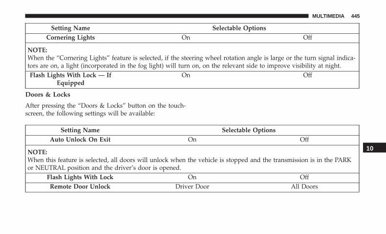
Setting Name Selectable OptionsCornering Lights On Off
NOTE:When the “Cornering Lights” feature is selected, if the steering wheel rotation angle is large or the turn signal indica-tors are on, a light (incorporated in the fog light) will turn on, on the relevant side to improve visibility at night.Flash Lights With Lock — If
EquippedOn Off
Doors & Locks
After pressing the “Doors & Locks” button on the touch-screen, the following settings will be available:
Setting Name Selectable OptionsAuto Unlock On Exit On Off
NOTE:When this feature is selected, all doors will unlock when the vehicle is stopped and the transmission is in the PARKor NEUTRAL position and the driver’s door is opened.
Flash Lights With Lock On OffRemote Door Unlock Driver Door All Doors
10
MULTIMEDIA 445

Setting Name Selectable OptionsPersonal Settings Linked To Key
Fob — If EquippedOn Off
Setting Name Selectable OptionsAuto Door Locks On Off
NOTE:When this feature is selected, all doors will lock automatically when the vehicle reaches a speed of 12 mph(20 km/h).
Engine Off Options — If Equipped
After pressing the “Engine Off Options” button on thetouchscreen, the following settings will be available:
Setting Name Selectable OptionsHeadlight Off Delay + -
Radio Off Delay 0 min 20 minRadio Off With Door On Off
446 MULTIMEDIA

Audio
After pressing the “Audio” button on the touchscreen, thefollowing settings will be available:
Setting Name Selectable OptionsBalance & Fade + -
NOTE:When in this display you may adjust the “Balance & Fade” of the audio by pressing and dragging the “Speaker Icon”toward any location in the box.
Equalizer Bass Mid Treble
NOTE:When in this display you may adjust the “Bass”, “Mid”, and “Treble” settings. Adjust the settings with the “+” and“–” setting buttons on the touchscreen or by selecting any point on the scale between the “+” and “–” buttons on thetouchscreen. Bass/Mid/Treble also allow you to simply slide your finger up or down to change the setting as well aspress directly on the desired setting.
Speed Adjusted Volume Off 1 2 3Loudness On Off
NOTE:The “Loudness” feature improves sound quality at lower volumes when enabled.
10
MULTIMEDIA 447
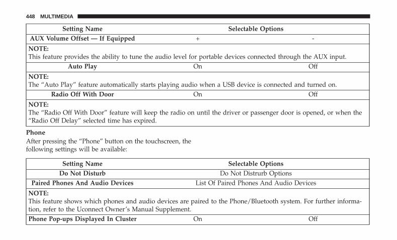
Setting Name Selectable OptionsAUX Volume Offset — If Equipped + -
NOTE:This feature provides the ability to tune the audio level for portable devices connected through the AUX input.
Auto Play On Off
NOTE:The “Auto Play” feature automatically starts playing audio when a USB device is connected and turned on.
Radio Off With Door On Off
NOTE:The “Radio Off With Door” feature will keep the radio on until the driver or passenger door is opened, or when the“Radio Off Delay” selected time has expired.
PhoneAfter pressing the “Phone” button on the touchscreen, thefollowing settings will be available:
Setting Name Selectable OptionsDo Not Disturb Do Not Distrurb Options
Paired Phones And Audio Devices List Of Paired Phones And Audio Devices
NOTE:This feature shows which phones and audio devices are paired to the Phone/Bluetooth system. For further informa-tion, refer to the Uconnect Owner’s Manual Supplement.Phone Pop-ups Displayed In Cluster On Off
448 MULTIMEDIA

SiriusXM Setup — If Equipped
After pressing the “SiriusXM Setup” button on the touch-screen, the following settings will be available:
Setting Name Selectable OptionsChannel Skip List Of Channels
NOTE:SiriusXM can be programmed to designate a group of channels that are the most desirable to listen to or to excludeundesirable channels while scanning. This feature allows you to select the channels you would like to skip.
Subscription Info Sirius ID
NOTE:New vehicle purchasers or lessees will receive a free limited time subscription to SiriusXM Satellite Radio with yourradio. Following the expiration of the free services, it will be necessary to access the information on the SubscriptionInformation screen to re-subscribe.
1. Press the “Subscription Info” button on the touchscreen to access the Subscription Information screen.
2. Write down the Sirius ID numbers for your receiver. To reactivate your service, either call the number listed on thescreen or visit the provider online.
10
MULTIMEDIA 449

Restore Settings
After pressing the “Restore Settings” button on the touch-screen, the following settings will be available:
Setting Name Selectable OptionsRestore Settings OK Cancel
NOTE:When this feature is selected it will reset all settings to their default settings.
Clear Personal Data
After pressing the “Clear Personal Data” button on thetouchscreen, the following settings will be available:
Setting Name Selectable OptionsClear Personal Data OK Cancel
NOTE:When this feature is selected it will remove all personal data including Bluetooth devices and presets.
450 MULTIMEDIA

Customer Programmable Features — Uconnect4/4C NAV Settings
Press the “Apps ” button, then press the “Settings” button on the touchscreen to display the menu
setting screen. In this mode the Uconnect system allowsyou to access all of the available programmable features.
NOTE:
• Only one touchscreen area may be selected at a time.
• Depending on the vehicles options, feature settings mayvary.
When making a selection, press the button on the touch-screen to enter the desired mode. Once in the desiredmode, press and release the preferred setting “option” untila check-mark appears next to the setting, showing thatsetting has been selected. Once the setting is complete,either press the Back Arrow button on the touchscreen toreturn to the previous menu, or press the “X” button on thetouchscreen to close out of the settings screen. Pressing theUp or Down Arrow button on the right side of the screenwill allow you to toggle up or down through the availablesettings.
The following tables list the settings that may be foundwithin the Uconnect 4/4C NAV radio, along with theselectable options pertaining to each setting.
Uconnect 4/4C NAV With 8.4–inch Display Buttons OnThe Touchscreen And Buttons On The Faceplate
1 — Uconnect Buttons On The Touchscreen2 — Uconnect Buttons On The Faceplate
10
MULTIMEDIA 451

Language
After pressing the “Language” button on the touchscreen,the following settings will be available:
Setting Name Selectable OptionsSet Language On Off
NOTE:When the “Set Language” feature is selected, you may select one of multiple languages (English / Français / Espa-ñol) for all display nomenclature, including the trip functions and the navigation system (if equipped). Press the “SetLanguage” button on the touchscreen, then press the desired language button on the touchscreen until a check-markappears next to the language, showing that setting has been selected.
Display
After pressing the “Display” button on the touchscreen, thefollowing settings will be available:
Setting Name Selectable OptionsDisplay Mode Manual Auto
Display Brightness WithHeadlights ON
+ -
NOTE:To make changes to the �Display Brightness with Headlights ON� setting, the headlights must be on and the interiordimmer switch must not be in the �party� or �parade� positions.
452 MULTIMEDIA

Setting Name Selectable OptionsDisplay Brightness With
Headlights OFF+ -
NOTE:To make changes to the �Display Brightness with Headlights OFF� setting, the headlights must be off and the interiordimmer switch must not be in the �party� or �parade� positions.
Set Theme Options On Off
NOTE:When in this display, you may select the theme for the display screen. To make your selection, press the �Set Theme�button on the touchscreen, then select the desired theme option button until a check-mark appears showing that thesetting has been selected.
Touchscreen Beep On OffControl Screen Time-Out On Off
NOTE:When the “Control Screen Time-Out” feature is selected, the Controls Screen will stay open for five seconds beforethe screen times out. With the feature deselected, the screen will stay open until it is manually closed.Navigation Turn-By-Turn In
ClusterOn Off
NOTE:When the “Navigation Turn-By-Turn In Cluster” feature is selected, the turn-by-turn directions will appear in the In-strument Cluster Display as the vehicle approaches a designated turn within a programmed route.
10
MULTIMEDIA 453

Setting Name Selectable OptionsPhone Pop-ups Displayed in
ClusterOn Off
Units
After pressing the “Units” button on the touchscreen, thefollowing settings will be available:
Setting Name Selectable OptionsUnits US Metric Custom
NOTE:• The “Metric” option changes the instrument cluster display to metric units of measure.• The “Custom” option allows setting the “Fuel Consumption” (L/100km, or km/L), “Pressure” (kPa, or bar), and
“Temperature” (°C or °F) units of measure independently.
Voice
After pressing the “Voice” button on the touchscreen, thefollowing settings will be available:
Setting Name Selectable OptionsVoice Response Length Brief DetailedShow Command List Always With Help Never
454 MULTIMEDIA
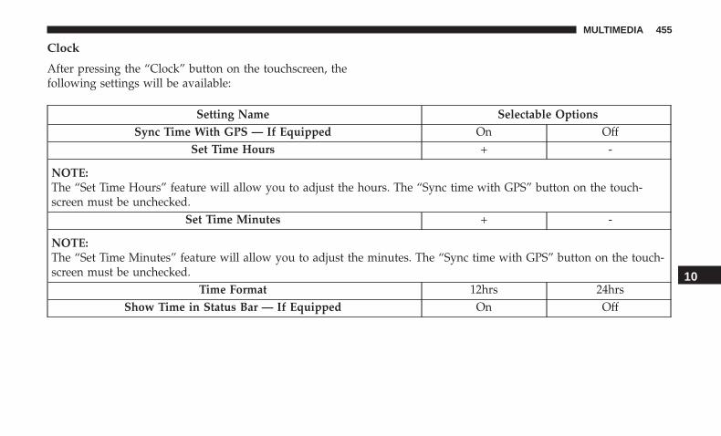
Clock
After pressing the “Clock” button on the touchscreen, thefollowing settings will be available:
Setting Name Selectable OptionsSync Time With GPS — If Equipped On Off
Set Time Hours + -
NOTE:The “Set Time Hours” feature will allow you to adjust the hours. The “Sync time with GPS” button on the touch-screen must be unchecked.
Set Time Minutes + -
NOTE:The “Set Time Minutes” feature will allow you to adjust the minutes. The “Sync time with GPS” button on the touch-screen must be unchecked.
Time Format 12hrs 24hrsShow Time in Status Bar — If Equipped On Off
10
MULTIMEDIA 455

Safety & Driving Assistance
After pressing the “Safety & Driving Assistance” button onthe touchscreen, the following settings will be available:
Setting Name Selectable OptionsForward Collision Warning Sensitivity — If Equipped Near Medium Far
NOTE:The “Forward Collision Warning Plus (FCW+) Sensitivity” setting determines at what relative distance the vehicledirectly in front of you needs to be at, before the system will warn you of a possible collision with the vehicle directlyin front of you, based on the option is selected. “Far” will give you the most amount of reaction time, whereas“Near” will give you the least amount of reaction time, based on the distance between the two vehicles.
Forward Collision Warning-Plus (FCW+) Off Sound Only Sound and Brake
NOTE:The “Forward Collision Warning Plus (FCW+)” setting includes Advanced Brake Assist (ABA). The ABA applies ad-ditional brake pressure when the driver requests insufficient brake pressure to avoid a potential frontal collision.When the “Sound Only” option is selected a chime will sound alerting you of a possible collision with the vehicle infront of you and more brake pressure is needed. When the “Sound and Brake” option is selected, it will apply thebrakes to slow your vehicle in case of potential forward collision and sound an audible chime to alert you.
LaneSense Warning — If Equipped Early Medium Late
NOTE:The “LaneSense Warning” setting determines at what distance the LaneSense system will warn you, through steeringwheel feedback, of a possible lane departure.
456 MULTIMEDIA

Setting Name Selectable OptionsParkSense — If Equipped Sound Only Sound and DisplayRear ParkSense Volume Low Medium High
Blind Spot Alert — If Equipped Off Lights Lights & Chime
NOTE:If your vehicle has experienced any damage in the area where the sensor is located, even if the fascia is not damaged,the sensor may have become misaligned. Take your vehicle to your authorized dealer to verify sensor alignment. Asensor that is misaligned will result in the BSM not operating to specification.
ParkView Backup Camera Active Guidelines On OffParkView Backup Camera Delay On Off
NOTE:The “ParkView Backup Camera Delay” setting determines whether or not the screen will display the rear view imagewith dynamic grid lines for up to ten seconds after the vehicle is shifted out of REVERSE. This delay will be canceledif the vehicle’s speed exceeds 8 mph (13 km/h), the transmission is shifted into PARK, or the ignition is switched tothe OFF position.
Rain Sensing Auto Wipers On OffSide Distance Warning Off Sound Sound and Dis-
playSide Distance Warning Volume Low Med High
10
MULTIMEDIA 457

Brakes
After pressing the “Brakes” button on the touchscreen, thefollowing settings will be available:
Setting Name Selectable OptionsElectric Park Brake Service Mode —
If EquippedYes No
NOTE:This feature provides a means for a technician or vehicle owner to utilize a vehicle integrated, menu driven system,to command the electric park brake retraction, to service the rear foundation brakes (brake pads, calipers, rotors, etc.).
Auto Park Brake On Off
Lights
After pressing the “Lights” button on the touchscreen, thefollowing settings will be available:
Setting Name Selectable OptionsHeadlight Sensitivity Level 1: minimum
sensitivityLevel 2: medium
sensitivityLevel 3: maximum sensitivity
NOTE:The greater the sensitivity set, the less the external light variation required to turn on the lights (e.g. with a setting onlevel 3 at sunset the headlights turn on earlier than in levels 1 and 2).
458 MULTIMEDIA

Setting Name Selectable OptionsHeadlight Off Delay 0 sec 30 sec 60 sec 90 sec
NOTE:When this feature is selected, it allows the adjustment of the amount of time the headlights remain on after the en-gine is shut off.Headlight Illumination On
Approach0 sec 30 sec 60 sec 90 sec
Greeting Lights On OffDaytime Running Lights On Off
Cornering Lights On Off
NOTE:When the “Cornering Lights” feature is selected, if the steering wheel rotation angle is large or the turn signal indica-tors are on, a light (incorporated in the fog light) will turn on, on the relevant side to improve visibility at night.Flash Lights With Lock — If
EquippedOn Off
Interior Ambient Lights + -
NOTE:The “Interior Ambient Lights” setting can also be adjusted by selecting any point on the scale between the “+” and“-” buttons on the touchscreen.
10
MULTIMEDIA 459

Setting Name Selectable OptionsAuto Dim High Beams — If
EquippedOn Off
NOTE:When the “Auto Dim High Beams” feature is selected, the high beam headlights will activate/deactivate automati-cally under certain conditions.
Doors & Locks
After pressing the “Doors & Locks” button on the touch-screen, the following settings will be available:
Setting Name Selectable OptionsAuto Unlock On Exit On Off
NOTE:When the “Auto Unlock On Exit” feature is selected, all doors will unlock when the vehicle is stopped, the transmis-sion is in the PARK or NEUTRAL position, and the driver’s door is opened.
Flash Lights With Lock On OffSound Horn With Lock — If Equipped Off 1st Press 2nd Press
Sound Horn With Remote Start — IfEquipped
On Off
460 MULTIMEDIA

Setting Name Selectable Options1st Press Of Key Fob Unlocks Driver Door All Doors
NOTE:When �Driver Door� is selected with 1st Press Of Key Fob Unlocks, only the driver’s door will unlock with the firstpress of the key fob unlock button. You must press the key fob unlock button twice to unlock the passenger’s doors.When �All Doors� is selected for 1st Press Of Key Fob Unlocks, all doors will unlock on the first press of the key fobunlock button. If the vehicle is programmed 1st Press Of Key Fob Unlocks “All Doors,” all doors will unlock, no mat-ter which Passive Entry equipped door handle is grasped. If 1st Press Of Key Fob Unlocks “Driver Door” is pro-grammed, only the driver’s door will unlock when the driver’s door is grasped. With Passive Entry, if 1st Press OfKey Fob Unlocks “Driver Door” is programmed, touching the handle more than once will result in only the driver’sdoor opening. If “Driver Door” is selected, once the driver door is opened, the interior door lock/unlock switch canbe used to unlock all doors (or use key fob).
Passive Entry — If Equipped On Off
NOTE:This feature allows you to lock and unlock the vehicles door(s) without having to push the key fob lock or unlockbuttons.
Personal Settings Linked to Key Fob — IfEquipped
On Off
NOTE:The “Personal Settings Linked To Key Fob” feature provides automatic recall of all settings stored to a memory loca-tion (driver’s seat, exterior mirrors, steering column position and radio station pre-sets) to enhance driver mobilitywhen entering and exiting the vehicle.
10
MULTIMEDIA 461

Auto Comfort Systems — If Equipped
After pressing the “Auto-On Comfort Systems” button onthe touchscreen, the following settings will be available:
Setting Name Selectable OptionsAuto-On Driver Heated/Ventilated Seat & Steering Wheel
With Vehicle Start — If EquippedOff Remote Start All Starts
NOTE:When this feature is selected the driver’s heated seat and heated steering wheel will automatically turn on when tem-peratures are below 40° F (4.4° C). When temperatures are above 80° F (26.7° C) the driver vented seat will turn on.
Engine Off Options
After pressing the “Engine Off Options” button on thetouchscreen, the following settings will be available:
Setting Name Selectable OptionsHeadlight Off Delay + -
462 MULTIMEDIA

Radio
After pressing the �Radio” on the touchscreen, the follow-ing settings will be available:
Setting Name Selectable OptionsRadio Off Delay 0 min 20 min
NOTE:When this feature is selected, the radio will stay on for 20 minutes, or until the first door is opened after the engine isshut off.
Audio
After pressing the “Audio” button on the touchscreen, thefollowing settings will be available:
Setting Name Selectable OptionsBalance/Fade Speaker Icon
NOTE:When in this display you may adjust the “Balance/Fade” of the audio by pressing and dragging the “Speaker Icon”toward any location in the box.
10
MULTIMEDIA 463

Setting Name Selectable OptionsEqualizer Bass Mid Treble
NOTE:When in this display you may adjust the “Bass”, “Mid”, and “Treble” settings. Adjust the settings with the “+” and“–” setting buttons on the touchscreen or by selecting any point on the scale between the “+” and “–” buttons on thetouchscreen. Bass/Mid/Treble also allow you to simply slide your finger up or down to change the setting as well aspress directly on the desired setting.
Speed Adjusted Volume Off 1 2 3Surround Sound — If Equipped On Off
AUX Volume Offset — If Equipped + -
NOTE:This feature provides the ability to tune the audio level for portable devices connected through the AUX input.
Phone/Bluetooth
After pressing the “Phone/Bluetooth” button on the touch-screen, the following settings will be available:
Setting Name Selectable OptionsDo Not Disturb List of Settings
NOTE:Press “Do Not Disturb” to access the available settings. The following settings are: Auto Reply (both, text, call), AutoReply Message (custom, default) and Custom Auto Reply Message (create message).
464 MULTIMEDIA

Setting Name Selectable OptionsPaired Phones List Of Paired Phones
NOTE:This feature shows which phones are paired to the Phone/Bluetooth system. For further information, refer to theUconnect Owner’s Manual Supplement.
Paired Audio Sources List Of Paired Audio Sources
NOTE:This feature shows which Audio Sources are paired to the Phone/Bluetooth system. For further information, refer tothe Uconnect Owner’s Manual Supplement.
SiriusXM Setup — If Equipped
After pressing the “SiriusXM Setup” button on the touch-screen, the following settings will be available:
Setting Name Selectable OptionsChannel Skip List Of Channels
NOTE:SiriusXM can be programmed to designate a group of channels that are the most desirable to listen to or to excludeundesirable channels while scanning. This feature allows you to select the channels you would like to skip.
10
MULTIMEDIA 465

Setting Name Selectable OptionsSubscription Info Sirius ID
NOTE:New vehicle purchasers or lessees will receive a free limited time subscription to SiriusXM Satellite Radio with yourradio. Following the expiration of the free services, it will be necessary to access the information on the SubscriptionInformation screen to re-subscribe.
1. Press the “Subscription Info” button on the touchscreen to access the Subscription Information screen.
2. Write down the Sirius ID numbers for your receiver. To reactivate your service, either call the number listed on thescreen or visit the provider online.
SiriusXM Travel Link is a separate subscription.
Radio Setup — If Equipped
After pressing the “Radio Setup” button (if equipped) onthe touchscreen, the following settings will be available:
Setting Name Selectable OptionsTraffic Announcement On Off
NOTE:Allows the system to pause the radio or a media device to issue a traffic bulletin.
466 MULTIMEDIA

Setting Name Selectable OptionsAlternative Frequency On Off
NOTE:Allows the frequency to change automatically to maintain the strongest signal.
Regional On Off
NOTE: Forces the system to select from a network station when the system is present in a different region.
Restore Settings
After pressing the “Restore Settings” button on the touch-screen, the following settings will be available:
Setting Name Selectable OptionsRestore Settings OK Cancel
NOTE:When this feature is selected it will reset all settings to their default settings.
10
MULTIMEDIA 467

Clear Personal Data
After pressing the “Clear Personal Data” button on thetouchscreen, the following settings will be available:
Setting Name Selectable OptionsClear Personal Data OK Cancel
NOTE:When this feature is selected it will remove all personal data including Bluetooth devices and presets.
System Information
After pressing the “System Information” button on thetouchscreen, the following settings will be available:
Setting Name Selectable OptionsSoftware Licenses Software Information Screen
NOTE:When this feature is selected, a “Licensing Information” screen will appear, displaying a licensing information websitefor the radio.
Map Update Download System Information ToUSB
Generate Request Code
NOTE:The “Download System Information To USB” will create a special USB required for Map updates of the radio.Whereas the “Generate Request Code” will display a code for the user to input online when downloading the maps.
468 MULTIMEDIA

STEERING WHEEL AUDIO CONTROLS
The remote sound system controls are located on the rearsurface of the steering wheel at the three and nine o’clockpositions.
The right-hand control is a rocker-type switch with apush-button in the center and controls the volume andmode of the sound system. Pushing the top of the rockerswitch will increase the volume, and pushing the bottom ofthe rocker switch will decrease the volume.
Pushing the center button will make the radio switchbetween the various modes available (AM/FM etc.).
The left-hand control is a rocker-type switch with a push-button in the center. The function of the left-hand control isdifferent depending on which mode you are in.
The following describes the left-hand control operation ineach mode.
Radio Operation
Pushing the top of the switch will “Seek” up for the nextlistenable station and pushing the bottom of the switch will“Seek” down for the next listenable station.
The button located in the center of the left-hand controlwill tune to the next preset station that you have pro-grammed in the radio preset button.
Media Mode
Pushing the top of the switch once goes to the next track onthe selected media (AUX/USB/Bluetooth). Pushing thebottom of the switch once goes to the beginning of thecurrent track, or to the beginning of the previous track if itis within eight seconds after the current track begins toplay.
If you push the switch up or down twice, it plays thesecond track; three times, it plays the third, etc.
Remote Sound System Controls10
MULTIMEDIA 469

AUX/USB/MP3 CONTROL
There is a USB and AUX Jack in the center console. Thisfeature allows an external device to be plugged into theUSB or AUX ports.
If equipped, there may also be another USB port (chargeonly) located on the back of the center console.
For further information, refer to the Uconnect Owner’sManual Supplement.
RADIO OPERATION AND MOBILE PHONES
Under certain conditions, the mobile phone being on inyour vehicle can cause erratic or noisy performance fromyour radio. This condition may be lessened or eliminatedby relocating the mobile phone antenna. This condition isnot harmful to the radio. If your radio performance does
Center Console USB Port
1 — USB Port2 — AUX Jack
Charge Only USB Port
470 MULTIMEDIA

not satisfactorily “clear” by the repositioning of the an-tenna, it is recommended that the radio volume be turneddown or off during mobile phone operation when notusing Uconnect (if equipped).
Regulatory And Safety Information
USA/CANADA
Exposure to Radio Frequency Radiation
The radiated output power of the internal wireless radio isfar below the FCC and IC radio frequency exposure limits.Nevertheless, the wireless radio will be used in such amanner that the radio is 20 cm or further from the humanbody.
The internal wireless radio operates within guidelinesfound in radio frequency safety standards and recommen-dations, which reflect the consensus of the scientific com-munity.
The radio manufacturer believes the internal wireless radiois safe for use by consumers. The level of energy emitted isfar less than the electromagnetic energy emitted by wire-less devices such as mobile phones. However, the use ofwireless radios may be restricted in some situations or
environments, such as aboard airplanes. If you are unsureof restrictions, you are encouraged to ask for authorizationbefore turning on the wireless radio.
The following regulatory statement applies to all RadioFrequency (RF) devices equipped in this vehicle:
This device complies with Part 15 of the FCC Rules andwith Industry Canada license-exempt RSS standard(s).Operation is subject to the following two conditions:
1. This device may not cause harmful interference, and
2. This device must accept any interference received, includ-ing interference that may cause undesired operation.
NOTE: Changes or modifications not expressly approvedby the party responsible for compliance could void theuser’s authority to operate the equipment.
NOTE:
• This equipment has been tested and found to complywith the limits for a Class B digital device, pursuant toPart 15 of the FCC Rules. These limits are designed toprovide reasonable protection against harmful interfer-ence in a residential installation. This equipment gener-ates, uses and can radiate radio frequency energy and, if
10
MULTIMEDIA 471

not installed and used in accordance with the instruc-tions, may cause harmful interference to radio commu-nications. However, there is no guarantee that interfer-ence will not occur in a particular installation.
• If this equipment does cause harmful interference toradio or television reception, which can be determinedby turning the equipment off and on, the user is encour-aged to try to correct the interference by one or more ofthe following measures:
1. Increase the separation between the equipment andreceiver.
2. Consult an authorized dealer or an experienced radiotechnician for help.
UCONNECT VOICE RECOGNITION QUICK TIPS
Introducing Uconnect
Start using Uconnect Voice Recognition with these helpfulquick tips. It provides the key Voice Commands and tipsyou need to know to control your Uconnect 3, Uconnect 4,or Uconnect 4/4C NAV system.
Uconnect 3 With 5–inch Display
472 MULTIMEDIA
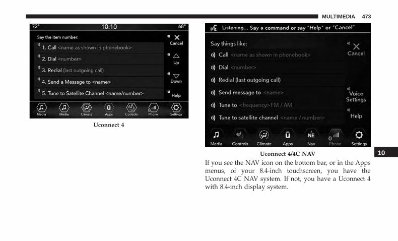
If you see the NAV icon on the bottom bar, or in the Appsmenus, of your 8.4-inch touchscreen, you have theUconnect 4C NAV system. If not, you have a Uconnect 4with 8.4-inch display system.
Uconnect 4
Uconnect 4/4C NAV 10
MULTIMEDIA 473

Get Started
All you need to control your Uconnect system with yourvoice are the buttons on your steering wheel.
Helpful hints for using Voice Recognition:
1. Visit UconnectPhone.com to check mobile device andfeature compatibility and to find phone pairing instruc-tions.
2. Reduce background noise. Wind and passenger conver-sations are examples of noise that may impact recogni-tion.
3. Speak clearly at a normal pace and volume while facingstraight ahead. The microphone is positioned on therearview mirror and aimed at the driver.
4. Each time you give a Voice Command, you must firstpush either the Voice Recognition (VR) or Phone button,wait until after the beep, then say your Voice Command.
5. You can interrupt the help message or system promptsby pushing the VR or Phone button and saying a VoiceCommand from current category.
Uconnect Voice Command Buttons
1 — Push To Initiate Or To Answer A Phone Call, Send Or ReceiveA Text2 — For All Radios: Push To Begin Radio, Media, or Climate Func-tions. For 8.4–inch System Only: Push To Begin Navigation Function3 — Push To End Call
474 MULTIMEDIA

Basic Voice Commands
The basic Voice Commands below can be given at anypoint while using your Uconnect system.
Push the VR button . After the beep, say:
• “ Cancel” to stop a current voice session
• “ Help” to hear a list of suggested Voice Commands
• “ Repeat” to listen to the system prompts again
Notice the visual cues that inform you of your voicerecognition system’s status. Cues appear on the touch-screen.
Radio
Use your voice to quickly get to the AM, FM or SiriusXMSatellite Radio stations you would like to hear. (Subscrip-tion or included SiriusXM Satellite Radio trial required.)
Push the VR button . After the beep, say:
• “ Tune to ninety-five-point-five FM”
• “ Tune to Satellite Channel Hits 1”
TIP: At any time, if you are not sure of what to say or wantto learn a Voice Command, push the VR button and say“ Help.” The system provides you with a list of com-mands.
Uconnect 3 Radio
10
MULTIMEDIA 475

Uconnect 4 Radio
Uconnect 4/4C NAV Radio
476 MULTIMEDIA

Media
Uconnect offers connections via USB, Bluetooth and auxil-iary ports (If Equipped). Voice operation is only availablefor connected USB and AUX devices. (Remote CD playeroptional and not available on all vehicles.)
Push the VR button . After the beep, say one of thefollowing commands and follow the prompts to switchyour media source or choose an artist.
• “ Change source to Bluetooth”
• “ Change source to AUX”
• “ Change source to USB”
• “ Play artist Beethoven”; “ Play album Greatest Hits”; “Play song Moonlight Sonata”; “ Play genre Classical”
TIP: Press the Browse button on the touchscreen to see allof the music on your USB device. Your Voice Commandmust match exactly how the artist, album, song and genreinformation is displayed.
Uconnect 3 Media
10
MULTIMEDIA 477

Uconnect 4 Media
Uconnect 4/4C NAV Media
478 MULTIMEDIA

Phone
Making and answering hands-free phone calls is easy withUconnect. When the Phonebook button is illuminated onyour touchscreen, your system is ready. CheckUconnectPhone.com for mobile phone compatibility andpairing instructions.
Push the VR button and the Phone button. After thebeep, say one of the following commands:
• “ Call John Smith”
• “ Dial 123-456-7890 and follow the system prompts”
• “ Redial (call previous outgoing phone number)”
• “ Call back (call previous incoming phone number)”
TIP: When providing a Voice Command, push the VRbutton and the Phone button and say “ Call,” thenpronounce the name exactly as it appears in your phonebook. When a contact has multiple phone numbers, youcan say “ Call John Smith work.”
Uconnect 3 Phone
10
MULTIMEDIA 479

Uconnect 4 Phone
Uconnect 4/4C NAV Phone
480 MULTIMEDIA

Voice Text Reply
Uconnect announces incoming text messages. Push thePhone or VR button and say “ Listen.” (Must havecompatible mobile phone paired to Uconnect system.)
1. Once an incoming text message is read to you, push thePhone or VR button . After the beep, say: “Reply.”
2. Listen to the Uconnect prompts. After the beep, repeatone of the pre-defined messages and follow the systemprompts.
PRE-DEFINED VOICE TEXT REPLY RESPONSESYes. Stuck in traffic. See you later.
No. Start withoutme. I’ll be late.
Okay. Where are you? I will be<number>
minutes late.Call me. Are you thereyet?
I’ll call you later. I needdirections.
See you in<number> of
minutes.I’m on my way. Can’t talk rightnow.I’m lost. Thanks.
TIP: Your mobile phone must have the full implementationof the Message Access Profile (MAP) to take advantage ofthis feature. For details about MAP, visitUconnectPhone.com.
Apple iPhone iOS 6 or later supports reading incomingtext messages only. To enable this feature on your AppleiPhone, follow these four simple steps:
iPhone Notification Settings
1 — Select “Settings”2 — Select “Bluetooth”3 — Select The (i) For The Paired Vehicle4 — Turn On “Show Notifications”
10
MULTIMEDIA 481

TIP: Voice Text Reply is not compatible with iPhone, but ifyour vehicle is equipped with Siri Eyes Free, you can useyour voice to send a text message.
Climate
Too hot? Too cold? Adjust vehicle temperatures hands-freeand keep everyone comfortable while you keep movingahead. (If vehicle is equipped with climate control.)
Push the VR button . After the beep, say one of thefollowing commands:
• “ Set driver temperature to 70 degrees”
• “ Set passenger temperature to 70 degrees”
TIP: Voice Command for Climate may only be used toadjust the interior temperature of your vehicle. VoiceCommand will not work to adjust the heated seats orsteering wheel if equipped.
Uconnect 4 Climate
482 MULTIMEDIA

Navigation (4C NAV)
The Uconnect navigation feature helps you save time andbecome more productive when you know exactly how toget to where you want to go.
1. To enter a destination, push the VR button . After thebeep, say: “ Find address 800 Chrysler Drive AuburnHills, Michigan.”
2. Then follow the system prompts.
TIP: To start a POI search, push the VR button . Afterthe beep, say: “ Find nearest coffee shop.”
Uconnect 4C/4C NAV Climate
Uconnect 4C NAV Navigation
10
MULTIMEDIA 483

SiriusXM Guardian (4C/4C NAV)— If Equipped
CAUTION!
Some SiriusXM Guardian services, including SOS Calland Roadside Assistance Call will NOT work withoutan operable LTE (voice/data) or 3G or 4G (data) net-work connection compatible with your device.
NOTE: Your vehicle may be transmitting data as autho-rized by the subscriber.
An included trial and/or subscription is required to takeadvantage of the SiriusXM Guardian services in the nextsection of this guide. To register with SiriusXM Guardian,press the Apps button on the Uconnect 4C/4C NAVtouchscreen to get started.
NOTE: SiriusXM Guardian is available only on equippedvehicles purchased within the continental United States,Alaska, Hawaii and Canada. Services can only be usedwhere coverage is available; see coverage map for details.
SOS Call
Theft Alarm Notification
Remote Door Lock/Unlock
Send & Go
Vehicle Finder
Stolen Vehicle Assistance
Remote Vehicle Start**
Remote Horn & Lights
Roadside Assistance Call
Vehicle Health Reports**
Vehicle Health Alert**
Performance Pages Plus**
**If vehicle is equipped.
Register (4C/4C NAV)
To unlock the full potential of SiriusXM Guardian in yourvehicle, you must activate your SiriusXM Guardian ser-vices.
1. Press the Apps icon on the bottom of your in-vehicletouchscreen.
2. Select the Activate Services icon from your list of apps.
484 MULTIMEDIA

3. Select “Customer Care” to speak with a SiriusXMGuardian Customer Care agent who will activate ser-vices in your vehicle, or select “Enter Email” to activateon the web.
• U.S. residents visit: www.siriusxm.com/guardian.
• Canadian residents visit: www.siriusxm.ca/guardian.
Vehicle Health Report/Alert (4C/4C NAV)
Your vehicle will send you a monthly email report, whichsummarizes the performance of your vehicle’s key systemsso you can stay on top of your vehicle’s maintenance needsif you are registered for SiriusXM Guardian. Your vehiclewill also send you Vehicle Health Alerts when it detectsissues with its key systems that need your attention. Forfurther information, refer to your owner’s manual.
Mobile App (4C/4C NAV)
You’re only a few steps away from using remote com-mands and sending a destination from your phone to yourvehicle.
To use the Uconnect Mobile App:
• Once you have registered your SiriusXM Guardianservices, download the Uconnect App to your mobiledevice. Use your Owner Account login and password toopen the app.
• Once on the “Remote” screen, you can begin usingRemote Door Lock/Unlock, Remote Vehicle Start, andactivate your horn and lights remotely, if equipped.
Mobile App
10
MULTIMEDIA 485

• Press the “Location” button on the bottom menu bar ofthe app to bring up a map to locate your vehicle or senda location to your Uconnect Navigation using VehicleFinder and Send & Go , if equipped.
• Press the “Settings” side menu in the upper left corner ofthe app to bring up app settings.
NOTE: For further information please visitDriveUconnect.com (U.S. Residents) or DriveUconnect.ca(Canadian Residents).
SiriusXM Travel Link (4C NAV)
Need to find a gas station, view local movie listings, checka sports score or the 5 - day weather forecast? SiriusXMTravel Link is a suite of services that brings a wealth ofinformation right to your Uconnect 4C NAV system. (Notavailable for Uconnect 4 system.)
Push the VR button . After the beep, say one of thefollowing commands:
• “ Show fuel prices”
• “ Show 5 - day weather forecast”
• “ Show extended weather”
TIP: Traffic alerts are not accessible with Voice Command.
Siri Eyes Free — If Equipped
Siri lets you use your voice to send text messages, selectmedia, place phone calls and much more. Siri uses yournatural language to understand what you mean and re-sponds back to confirm your requests. The system isdesigned to keep your eyes on the road and your hands onthe wheel by letting Siri help you perform useful tasks.
SiriusXM Travel Link
486 MULTIMEDIA

To enable Siri, push and hold, then release the UconnectVoice Recognition (VR) button on the steering wheel. Afteryou hear a double beep you can ask Siri to play podcastsand music, get directions, read text messages and manyother useful requests.
Using Do Not Disturb
With Do Not Disturb, you can disable notifications fromincoming calls and texts, allowing you to keep your eyeson the road and hands on the wheel. For your convenience,there is a counter display to keep track of your missed callsand text messages while you were using Do Not Disturb.
Uconnect 4 Siri Eyes Free Available
Uconnect 4C/4C NAV With 8.4–inch Siri Eyes FreeAvailable
10
MULTIMEDIA 487

Do Not Disturb can automatically reply with a text mes-sage, a call or both, when declining an incoming call andsend it to voicemail.
Automatic reply messages can be:
• “I am driving right now, I will get back to you shortly.”
• Create a custom auto reply message up to 160 characters.
While in Do Not Disturb, Conference Call can be selectedso you can still place a second call without being inter-rupted by incoming calls.
NOTE:
• Only the beginning of your custom message will be seenon the touchscreen.
• Reply with text message is not compatible with iPhones.
• Auto reply with text message is only available onphones that supporting Bluetooth MAP.
Android Auto — If Equipped
Android Auto allows you to use your voice to interact withAndroid’s best-in-class speech technology through yourvehicle’s voice recognition system, and use your smart-phone’s data plan to project your Android powered smart-phone and a number of its apps onto your Uconnecttouchscreen. Connect your Android 5.0 (Lollipop), orhigher, to one of the media USB ports, using the factory-provided USB cable, and press the new Android Auto iconthat replaces your “Phone” icon on the main menu bar tobegin Android Auto. Push and hold the VR button on thesteering wheel, or press and hold the “Microphone” iconwithin Android Auto, to activate Android’s VR, whichrecognizes natural voice commands, to use a list of yoursmartphone’s features:
• Maps
• Music
• Phone
• Text Messages
• Additional Apps
488 MULTIMEDIA

Refer to your Uconnect Owner’s Manual Supplement forfurther information.
Android Auto On 7-inch Display
Android Auto On 8.4-inch Display 10
MULTIMEDIA 489
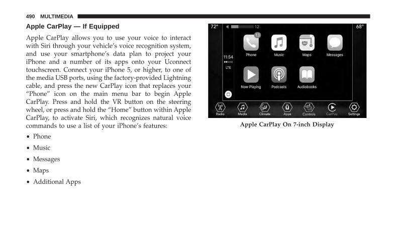
Apple CarPlay — If Equipped
Apple CarPlay allows you to use your voice to interactwith Siri through your vehicle’s voice recognition system,and use your smartphone’s data plan to project youriPhone and a number of its apps onto your Uconnecttouchscreen. Connect your iPhone 5, or higher, to one ofthe media USB ports, using the factory-provided Lightningcable, and press the new CarPlay icon that replaces your“Phone” icon on the main menu bar to begin AppleCarPlay. Press and hold the VR button on the steeringwheel, or press and hold the “Home” button within AppleCarPlay, to activate Siri, which recognizes natural voicecommands to use a list of your iPhone’s features:
• Phone
• Music
• Messages
• Maps
• Additional Apps
Apple CarPlay On 7-inch Display
490 MULTIMEDIA

Refer to your Uconnect Owner’s Manual Supplement forfurther information.
General Information
The following regulatory statement applies to all RadioFrequency (RF) devices equipped in this vehicle:
This device complies with Part 15 of the FCC Rules andwith Industry Canada license-exempt RSS standard(s).Operation is subject to the following two conditions:
1. This device may not cause harmful interference, and
2. This device must accept any interference received, in-cluding interference that may cause undesired opera-tion.
NOTE: Changes or modifications not expressly approvedby the party responsible for compliance could void theuser’s authority to operate the equipment.
Apple CarPlay On 8.4-inch Display 10
MULTIMEDIA 491

Additional Information
© 2017 FCA US LLC. All rights reserved. Mopar andUconnect are registered trademarks and Mopar OwnerConnect is a trademark of FCA US LLC. Android is atrademark of Google Inc. SiriusXM and all related marksand logos are trademarks of SiriusXM Radio Inc.
For Uconnect system support, call: 1-877-855-8400 (24hours a day 7 days a week) or visit DriveUconnect.com(U.S. Residents) or DriveUconnect.ca (Canadian Resi-dents).
CD MAINTENANCE
To keep a CD in good condition, take the followingprecautions:
1. Handle the disc by its edge; avoid touching the surface.
2. If the disc is stained, clean the surface with a soft cloth,wiping from center to edge.
3. Do not apply paper or tape to the disc; avoid scratchingthe disc.
4. Do not use solvents such as benzene, thinner, cleaners,or anti-static sprays.
5. Store the disc in its case after playing.
6. Do not expose the disc to direct sunlight.
7. Do not store the disc where temperatures may becometoo high.
NOTE: If you experience difficulty in playing a particulardisc, it may be damaged (e.g., scratched, reflective coatingremoved, a hair, moisture or dew on the disc), oversized, orhave protection encoding. Try a known good disc beforeconsidering disc player service.
492 MULTIMEDIA

CUSTOMER ASSISTANCE
CONTENTS� SUGGESTIONS FOR OBTAINING SERVICE FOR
YOUR VEHICLE . . . . . . . . . . . . . . . . . . . . . . . .494
▫ Prepare For The Appointment . . . . . . . . . . . . . .494
▫ Prepare A List . . . . . . . . . . . . . . . . . . . . . . . . .494
▫ Be Reasonable With Requests . . . . . . . . . . . . . .494
� IF YOU NEED ASSISTANCE . . . . . . . . . . . . . . . .494
▫ FCA US LLC Customer Center . . . . . . . . . . . . .495
▫ FCA Canada Inc. Customer Center. . . . . . . . . . .495
▫ In Mexico Contact . . . . . . . . . . . . . . . . . . . . . .495
▫ Puerto Rico And U.S. Virgin Islands. . . . . . . . . .495
▫ Customer Assistance For The Hearing Or SpeechImpaired (TDD/TTY) . . . . . . . . . . . . . . . . . . . .496
▫ Service Contract . . . . . . . . . . . . . . . . . . . . . . .496
� WARRANTY INFORMATION . . . . . . . . . . . . . . .497
� MOPAR PARTS . . . . . . . . . . . . . . . . . . . . . . . . .497
� REPORTING SAFETY DEFECTS . . . . . . . . . . . . .497
▫ In The 50 United States And Washington, D.C. . .497
▫ In Canada . . . . . . . . . . . . . . . . . . . . . . . . . . . .498
� PUBLICATION ORDER FORMS . . . . . . . . . . . . .49811

SUGGESTIONS FOR OBTAINING SERVICE FORYOUR VEHICLE
Prepare For The Appointment
If you are having warranty work done, be sure to have theright papers with you. Take your warranty folder. All workto be performed may not be covered by the warranty.Discuss additional charges with the service manager. Keepa maintenance log of your vehicle’s service history. Thiscan often provide a clue to the current problem.
Prepare A List
Make a written list of your vehicle’s problems or thespecific work you want done. If you’ve had an accident orwork done that is not on your maintenance log, let theservice advisor know.
Be Reasonable With Requests
If you list a number of items and you must have yourvehicle by the end of the day, discuss the situation with theservice advisor and list the items in order of priority. Atmany authorized dealers, you may obtain a rental vehicleat a minimal daily charge. If you need a rental, it isadvisable to make these arrangements when you call for anappointment.
IF YOU NEED ASSISTANCE
The manufacturer and its authorized dealer are vitallyinterested in your satisfaction. We want you to be happywith our products and services.
Warranty service must be done by an authorized dealer. Westrongly recommend that you take the vehicle to an autho-rized dealer. They know your vehicle the best, and are mostconcerned that you get prompt and high quality service.The manufacturer’s authorized dealer have the facilities,factory-trained technicians, special tools, and the latestinformation to ensure the vehicle is fixed correctly and in atimely manner.
This is why you should always talk to an authorized dealerservice manager first. Most matters can be resolved withthis process.
• If for some reason you are still not satisfied, talk to thegeneral manager or owner of the authorized dealer.They want to know if you need assistance.
• If an authorized dealer is unable to resolve the concern,you may contact the manufacturer’s customer center.
494 CUSTOMER ASSISTANCE

Any communication to the manufacturer’s customer centershould include the following information:
• Owner’s name and address
• Owner’s telephone number (home and office)
• Authorized dealer name
• Vehicle Identification Number (VIN)
• Vehicle delivery date and mileage
FCA US LLC Customer Center
P.O. Box 21–8004
Auburn Hills, MI 48321–8004
Phone: (877) 426-5337
FCA Canada Inc. Customer Center
P.O. Box 1621
Windsor, Ontario N9A 4H6
Phone: (800) 465-2001 English / (800) 387-9983 French
In Mexico Contact
Av. Prolongacion Paseo de la Reforma, 1240
Sante Fe C.P. 05109
Mexico, D. F.
In Mexico City: 5081-7568
Outside Mexico City: 1-800-505-1300
Puerto Rico And U.S. Virgin Islands
FCA Caribbean LLC
P.O. Box 191857
San Juan 00919-1857
Phone: (877) 426-5337
Fax: (787) 782-3345
11
CUSTOMER ASSISTANCE 495

Customer Assistance For The Hearing Or SpeechImpaired (TDD/TTY)
To assist customers who have hearing difficulties, themanufacturer has installed special TDD (Telecommunica-tion Devices for the Deaf) equipment at its customer center.Any hearing or speech impaired customer, who has accessto a TDD or a conventional teletypewriter (TTY) in theUnited States, can communicate with the manufacturer bydialing 1-800-380-CHRY.
Canadian residents with hearing difficulties that requireassistance can use the special needs relay service offered byBell Canada. For TTY teletypewriter users, dial 711 and forVoice callers, dial 1-800-855-0511 to connect with a BellRelay Service operator.
Service Contract
You may have purchased a service contract for a vehicle tohelp protect you from the high cost of unexpected repairsafter the manufacturer’s New Vehicle Limited Warrantyexpires. The manufacturer stands behind only the manu-facturer’s service contracts. If you purchased a manufac-turer’s service contract, you will receive Plan Provisionsand an Owner Identification Card in the mail within threeweeks of the vehicle delivery date. If you have any
questions about the service contract, call the manufactur-er’s Service Contract National Customer Hotline at 1-800-521-9922 (Canadian residents, call (800) 465-2001 English /(800) 387-9983 French).
The manufacturer will not stand behind any service con-tract that is not the manufacturer’s service contract. It is notresponsible for any service contract other than the manu-facturer’s service contract. If you purchased a servicecontract that is not a manufacturer’s service contract, andyou require service after the manufacturer’s New VehicleLimited Warranty expires, please refer to the contractdocuments, and contact the person listed in those docu-ments.
We appreciate that you have made a major investmentwhen you purchased the vehicle. An authorized dealer hasalso made a major investment in facilities, tools, andtraining to assure that you are absolutely delighted withthe ownership experience. You will be pleased with theirsincere efforts to resolve any warranty issues or relatedconcerns.
496 CUSTOMER ASSISTANCE

WARNING!
Engine exhaust (internal combustion engines only),some of its constituents, and certain vehicle compo-nents contain, or emit, chemicals known to the State ofCalifornia to cause cancer and birth defects, or otherreproductive harm. In addition, certain fluids con-tained in vehicles and certain products of componentwear contain, or emit, chemicals known to the State ofCalifornia to cause cancer and birth defects, or otherreproductive harm.
WARRANTY INFORMATION
See the Warranty Information Booklet for the terms andprovisions of FCA US LLC warranties applicable to thisvehicle and market.
MOPAR PARTS
Mopar fluids, lubricants, parts, and accessories are avail-able from an authorized dealer. They are recommended foryour vehicle in order to help keep the vehicle operating atits best.
REPORTING SAFETY DEFECTS
In The 50 United States And Washington, D.C.
If you believe that your vehicle has a defect that couldcause a crash or cause injury or death, you shouldimmediately inform the National Highway TrafficSafety Administration (NHTSA) in addition to notifyingFCA US LLC.
If NHTSA receives similar complaints, it may open aninvestigation, and if it finds that a safety defect exists ina group of vehicles, it may order a recall and remedycampaign. However, NHTSA cannot become involvedin individual problems between you, an authorizeddealer or FCA US LLC.
To contact NHTSA, you may call the Vehicle SafetyHotline toll free at 1-888-327-4236 (TTY: 1-800-424-9153);or go to http://www.safercar.gov; or write to: Admin-istrator, NHTSA, 1200 New Jersey Avenue, SE., WestBuilding, Washington, D.C. 20590. You can also obtainother information about motor vehicle safety fromhttp://www.safercar.gov.
11
CUSTOMER ASSISTANCE 497

In Canada
If you believe that your vehicle has a safety defect, youshould contact the Customer Service Department imme-diately. Canadian customers who wish to report a safetydefect to the Canadian government should contactTransport Canada, Motor Vehicle Defect Investigationsand Recalls at 1-800-333-0510 or go to http://www.tc.gc.ca/roadsafety/.
PUBLICATION ORDER FORMS
To order the following manuals, you may use either thewebsite or the phone numbers listed below. Visa, Master-card, American Express, and Discover orders are accepted.
Service Manuals
These comprehensive Service Manuals provide the infor-mation that students and professional technicians need indiagnosing/troubleshooting, problem solving, maintain-ing, servicing, and repairing FCA US LLC vehicles. Acomplete working knowledge of the vehicle, system,and/or components is written in straightforward languagewith illustrations, diagrams, and charts.
Diagnostic Procedure Manuals
Diagnostic Procedure Manuals are filled with diagrams,charts and detailed illustrations. These practical manualsmake it easy for students and technicians to find and fixproblems on computer-controlled vehicle systems and fea-tures. They show exactly how to find and correct problemsthe first time, using step-by-step troubleshooting and driv-ability procedures, proven diagnostic tests and a completelist of all tools and equipment.
Owner’s Manuals
These Owner’s Manuals have been prepared with theassistance of service and engineering specialists to acquaintyou with specific FCA US LLC vehicles. Included arestarting, operating, emergency and maintenance proce-dures as well as specifications, capabilities and safety tips.
Call toll free at:
• 1-800-890-4038 (U.S.)
• 1-800-387-1143 (Canada)
Or
Visit us on the Worldwide Web at:
• www.techauthority.com (U.S.)
498 CUSTOMER ASSISTANCE

INDEX
12

Adding Engine Coolant (Antifreeze) . . . . . . . . . . . . .372Additives, Fuel . . . . . . . . . . . . . . . . . . . . . . . . . . . .412Air Bag . . . . . . . . . . . . . . . . . . . . . . . . . . . . . . . . .181
Air Bag Operation . . . . . . . . . . . . . . . . . . . . . . . .183Air Bag Warning Light . . . . . . . . . . . . . . . . .180, 184Driver Knee Air Bag . . . . . . . . . . . . . . . . . . . . . .191Enhanced Accident Response . . . . . . . . . . . . .196, 353Event Data Recorder (EDR) . . . . . . . . . . . . . . . . .353Front Air Bag . . . . . . . . . . . . . . . . . . . . . . . . . . .184If Deployment Occurs . . . . . . . . . . . . . . . . . . . . .195Knee Impact Bolsters . . . . . . . . . . . . . . . . . . . . . .190Maintaining Your Air Bag System . . . . . . . . . . . . .199Maintenance . . . . . . . . . . . . . . . . . . . . . . . . . . . .199Redundant Air Bag Warning Light . . . . . . . . . . . .181Side Air Bags . . . . . . . . . . . . . . . . . . . . . . . . . . .191Transporting Pets . . . . . . . . . . . . . . . . . . . . . . . .215
Air Bag Light . . . . . . . . . . . . . . . . . . . . . . .116, 180, 216Air Cleaner, Engine (Engine Air Cleaner Filter). . . . . .364Air Conditioner Maintenance . . . . . . . . . . . . . . . . . .365Air Conditioning Filter . . . . . . . . . . . . . . . . . . . .77, 366Air Conditioning, Operating Tips . . . . . . . . . . . . . . . .76Air Conditioning Refrigerant . . . . . . . . . . . . . . .365, 366Air Conditioning System. . . . . . . . . . . . . . . . . . .75, 365Air Filter . . . . . . . . . . . . . . . . . . . . . . . . . . . . . . . .364
Air PressureTires . . . . . . . . . . . . . . . . . . . . . . . . . . . . . . . . . .389
AlarmArm The System . . . . . . . . . . . . . . . . . . . . . . . . . .32Disarm The System . . . . . . . . . . . . . . . . . . . . . . . .32Security Alarm . . . . . . . . . . . . . . . . . . . . . . . . . .120
Alarm (Security Alarm) . . . . . . . . . . . . . . . . . . . . . . .31Alarm System (Security Alarm) . . . . . . . . . . . . . . . . .31Alterations/Modifications, Vehicle . . . . . . . . . . . . . . . .7Antifreeze (Engine Coolant) . . . . . . . . . . . . . . . .372, 414
Disposal . . . . . . . . . . . . . . . . . . . . . . . . . . . . . . .374Anti-Lock Brake System (ABS) . . . . . . . . . . . . . . . . .134Anti-Lock Warning Light . . . . . . . . . . . . . . . . . . . . .120Arming System (Security Alarm) . . . . . . . . . . . . . . . .31Assist, Hill Start . . . . . . . . . . . . . . . . . . . . . . . . . . .144Audio Systems (Radio). . . . . . . . . . . . . . . . . . . . . . .419Auto Down Power Windows . . . . . . . . . . . . . . . . . . .79Automatic Dimming Mirror . . . . . . . . . . . . . . . . .50, 51Automatic Door Locks. . . . . . . . . . . . . . . . . . . . . . . .38Automatic Headlights . . . . . . . . . . . . . . . . . . . . . . . .57Automatic High Beams . . . . . . . . . . . . . . . . . . . . . . .56Automatic Temperature Control (ATC) . . . . . . . . . . . .75Automatic Transaxle . . . . . . . . . . . . . . . . . . . . . . . .239Automatic Transmission . . . . . . . . . . . . . . . . . .241, 378
Adding Fluid . . . . . . . . . . . . . . . . . . . . . . . .378, 416
500 INDEX

Fluid And Filter Changes . . . . . . . . . . . . . . . . . . .378Fluid Change . . . . . . . . . . . . . . . . . . . . . . . . . . .378Fluid Level Check . . . . . . . . . . . . . . . . . . . . .377, 378Fluid Type . . . . . . . . . . . . . . . . . . . . . . . . . .377, 416Special Additives . . . . . . . . . . . . . . . . . . . . . . . . .377
Auto Unlock, Doors . . . . . . . . . . . . . . . . . . . . . . . . .38Auto Up Power Windows . . . . . . . . . . . . . . . . . . . . .79Auxiliary Electrical Outlet (Power Outlet) . . . . . . . . . .93Auxiliary Power Outlet . . . . . . . . . . . . . . . . . . . . . . .93Axle Fluid . . . . . . . . . . . . . . . . . . . . . . . . . . . . . . .416Axle Lubrication . . . . . . . . . . . . . . . . . . . . . . . . . . .416
Battery . . . . . . . . . . . . . . . . . . . . . . . . . . . . . . .117, 362Charging System Light . . . . . . . . . . . . . . . . . . . . .117Keyless Key Fob Replacement . . . . . . . . . . . . . . . .20
Belts, Seat . . . . . . . . . . . . . . . . . . . . . . . . . . . . . . . .216Blind Spot Monitoring . . . . . . . . . . . . . . . . . . . . . . .146Body Mechanism Lubrication . . . . . . . . . . . . . . . . . .366B-Pillar Location . . . . . . . . . . . . . . . . . . . . . . . . . . .384Brake Assist System. . . . . . . . . . . . . . . . . . . . . . . . .136Brake Control System, Electronic. . . . . . . . . . . . . . . .135Brake Fluid . . . . . . . . . . . . . . . . . . . . . . . . . . . . . . .416Brake System . . . . . . . . . . . . . . . . . . . . . . . . . . . . .375
Fluid Check . . . . . . . . . . . . . . . . . . . . . . . . .375, 416Master Cylinder . . . . . . . . . . . . . . . . . . . . . . . . .375
Parking . . . . . . . . . . . . . . . . . . . . . . . . . . . . . . .230Warning Light . . . . . . . . . . . . . . . . . . . . . . . . . . .116
Brake/Transmission Interlock . . . . . . . . . . . . . . . . . .240Brightness, Interior Lights . . . . . . . . . . . . . . . . . . .59, 60Bulb Replacement . . . . . . . . . . . . . . . . . . . . . . . . . .301Bulbs, Light . . . . . . . . . . . . . . . . . . . . . . . . . . . . . .219
Camera, Rear . . . . . . . . . . . . . . . . . . . . . . . . . . . . .273Capacities, Fluid . . . . . . . . . . . . . . . . . . . . . . . . . . .414Caps, Filler
Fuel . . . . . . . . . . . . . . . . . . . . . . . . . . . . . . . . . .274Oil (Engine) . . . . . . . . . . . . . . . . . . . . . . . . .360, 363Radiator (Coolant Pressure) . . . . . . . . . . . . . . . . .373
Carbon Monoxide Warning . . . . . . . . . . . . . . . .216, 413Cargo Area Features . . . . . . . . . . . . . . . . . . . . . . . . .89Cargo Load Floor . . . . . . . . . . . . . . . . . . . . . . . . . . .89Cargo Tie-Downs . . . . . . . . . . . . . . . . . . . . . . . . .89, 91Car Washes. . . . . . . . . . . . . . . . . . . . . . . . . . . . . . .403Cellular Phone . . . . . . . . . . . . . . . . . . . . . . . . . . . .470Certification Label . . . . . . . . . . . . . . . . . . . . . . . . . .276Chains, Tire . . . . . . . . . . . . . . . . . . . . . . . . . . . . . .396Change Oil Indicator . . . . . . . . . . . . . . . . . . . . . . . .105Changing A Flat Tire . . . . . . . . . . . . . . . . . . . . .324, 378Chart, Tire Sizing. . . . . . . . . . . . . . . . . . . . . . . . . . .380Check Engine Light (Malfunction Indicator Light). . . .130
12
INDEX 501

Checking Your Vehicle For Safety . . . . . . . . . . . . . . .215Checks, Safety . . . . . . . . . . . . . . . . . . . . . . . . . . . . .215Child Restraint . . . . . . . . . . . . . . . . . . . . . . . . . . . .200Child Restraints
Booster Seats . . . . . . . . . . . . . . . . . . . . . . . . . . . .203Child Seat Installation . . . . . . . . . . . . . . . . . . . . .212How To Stow An unused ALR Seat Belt . . . . . . . .210Infants And Child Restraints . . . . . . . . . . . . . . . .202Lower Anchors And Tethers For Children . . . . . . .205Older Children And Child Restraints . . . . . . . . . . .202Seating Positions . . . . . . . . . . . . . . . . . . . . . . . . .204
Child Safety Locks . . . . . . . . . . . . . . . . . . . . . . . . . .38Clean Air Gasoline. . . . . . . . . . . . . . . . . . . . . . . . . .411Cleaning
Wheels . . . . . . . . . . . . . . . . . . . . . . . . . . . . . . . .401Windshield Wiper Blades . . . . . . . . . . . . . . . . . . .366
Climate Control . . . . . . . . . . . . . . . . . . . . . . . . . . . .65Manual . . . . . . . . . . . . . . . . . . . . . . . . . . . . . . . .65
Coin Holder . . . . . . . . . . . . . . . . . . . . . . . . . . . . . . .92Cold Weather Operation. . . . . . . . . . . . . . . . . . . . . .226Compact Disc (CD) Maintenance. . . . . . . . . . . . . . . .492Compact Spare Tire . . . . . . . . . . . . . . . . . . . . . . . . .395Computer, Trip/Travel . . . . . . . . . . . . . . . . . . . . . . .115Connector
UCI . . . . . . . . . . . . . . . . . . . . . . . . . . . . . . . . . .470
Universal Consumer Interface (UCI) . . . . . . . . . . .470Console . . . . . . . . . . . . . . . . . . . . . . . . . . . . . . . . . .92Console, Floor . . . . . . . . . . . . . . . . . . . . . . . . . . . . .92Contract, Service . . . . . . . . . . . . . . . . . . . . . . . . . . .496Cooling Pressure Cap (Radiator Cap) . . . . . . . . . . . .373Cooling System . . . . . . . . . . . . . . . . . . . . . . . . . . . .371
Adding Coolant (Antifreeze) . . . . . . . . . . . . . . . . .372Coolant Capacity . . . . . . . . . . . . . . . . . . . . . . . . .414Coolant Level . . . . . . . . . . . . . . . . . . . . . . . .371, 374Disposal Of Used Coolant . . . . . . . . . . . . . . . . . .374Drain, Flush, And Refill . . . . . . . . . . . . . . . . . . . .371Inspection . . . . . . . . . . . . . . . . . . . . . . . . . . . . . .374Points To Remember . . . . . . . . . . . . . . . . . . . . . .374Pressure Cap . . . . . . . . . . . . . . . . . . . . . . . . . . . .373Radiator Cap . . . . . . . . . . . . . . . . . . . . . . . . . . .373Selection Of Coolant (Antifreeze) . . . . . . .372, 414, 415
Corrosion Protection . . . . . . . . . . . . . . . . . . . . . . . .401Cruise Light. . . . . . . . . . . . . . . . . . . . . . . .127, 128, 129Cupholders . . . . . . . . . . . . . . . . . . . . . . . . . . . . . . .93Customer Assistance . . . . . . . . . . . . . . . . . . . . . . . .494Customer Programmable Features . . . . . . . . . . . . . . .422Cybersecurity . . . . . . . . . . . . . . . . . . . . . . . . . . . . .420
Daytime Running Lights . . . . . . . . . . . . . . . . . . . . . .55Dealer Service . . . . . . . . . . . . . . . . . . . . . . . . . . . . .362
502 INDEX

Defroster, Windshield. . . . . . . . . . . . . . . . . . . . . . . .217Diagnostic System, Onboard . . . . . . . . . . . . . . . . . . .129Dimmer Switch, Headlight . . . . . . . . . . . . . . . . . .55, 56Dipsticks
Oil (Engine) . . . . . . . . . . . . . . . . . . . . . . . . . . . .361Disabled Vehicle Towing . . . . . . . . . . . . . . . . . . . . .349Disposal
Antifreeze (Engine Coolant) . . . . . . . . . . . . . . . . .374Disturb. . . . . . . . . . . . . . . . . . . . . . . . . . . . . . . . . .487Door Ajar . . . . . . . . . . . . . . . . . . . . . . . . . . . . .118, 119Door Ajar Light. . . . . . . . . . . . . . . . . . . . . . . . .118, 119Driver’s Seat Back Tilt . . . . . . . . . . . . . . . . . . . . . . . .40Driver’s Seat Tilt Back . . . . . . . . . . . . . . . . . . . . . . . .39Driving. . . . . . . . . . . . . . . . . . . . . . . . . . . . . . . . . .288
Electrical Outlet, Auxiliary (Power Outlet) . . . . . . . . . .93Electric Brake Control System
Anti-Lock Brake System . . . . . . . . . . . . . . . . . . . .134Electric Parking Brake . . . . . . . . . . . . . . . . . . . . . . .230Electronic Brake Control System . . . . . . . . . . . . . . . .135
Traction Control System . . . . . . . . . . . . . . . . . . . .135Electronic Speed Control (Cruise Control) . . . . . . . . .256Electronic Stability Control (ESC) . . . . . . . . . . . . . . .137Electronic Throttle Control Warning Light . . . . . . . . .118
Emergency, In Case OfHazard Warning Flasher . . . . . . . . . . . . . . . . . . .295Jacking . . . . . . . . . . . . . . . . . . . . . . . . . . . .324, 378Jump Starting . . . . . . . . . . . . . . . . . . . . . . . . . . .343Overheating . . . . . . . . . . . . . . . . . . . . . . . . . . . .346Tow Hooks . . . . . . . . . . . . . . . . . . . . . . . . . . . . .352Towing . . . . . . . . . . . . . . . . . . . . . . . . . . . . . . . .349
Emission Control System Maintenance. . . . . . . . . . . .130Engine . . . . . . . . . . . . . . . . . . . . . . . . . . . . . . . . . .360
Air Cleaner . . . . . . . . . . . . . . . . . . . . . . . . . . . . .364Block Heater . . . . . . . . . . . . . . . . . . . . . . . . . . . .228Break-In Recommendations . . . . . . . . . . . . . . . . .229Checking Oil Level . . . . . . . . . . . . . . . . . . . . . . .361Coolant (Antifreeze) . . . . . . . . . . . . . . . . . . . . . .415Cooling . . . . . . . . . . . . . . . . . . . . . . . . . . . . . . .371Exhaust Gas Caution . . . . . . . . . . . . . . . . . . .216, 413Fails To Start . . . . . . . . . . . . . . . . . . . . . . . . . . . .227Flooded, Starting . . . . . . . . . . . . . . . . . . . . . . . . .227Jump Starting . . . . . . . . . . . . . . . . . . . . . . . . . . .343Oil . . . . . . . . . . . . . . . . . . . . . . . . . . . .363, 414, 415Oil Filler Cap . . . . . . . . . . . . . . . . . . . . . . . .360, 363Oil Filter . . . . . . . . . . . . . . . . . . . . . . . . . . . . . . .364Oil Selection . . . . . . . . . . . . . . . . . . . . . . . . .363, 414Oil Synthetic . . . . . . . . . . . . . . . . . . . . . . . . . . . .364Overheating . . . . . . . . . . . . . . . . . . . . . . . . . . . .346
12
INDEX 503

Starting . . . . . . . . . . . . . . . . . . . . . . . . . . . . . . .224Engine Oil Viscosity. . . . . . . . . . . . . . . . . . . . . . . . .363Engine Oil Viscosity Chart . . . . . . . . . . . . . . . . . . . .363Enhanced Accident Response Feature . . . . . . . . .196, 353Ethanol. . . . . . . . . . . . . . . . . . . . . . . . . . . . . . . . . .411Exhaust Gas Caution . . . . . . . . . . . . . . . . . . . . . . . .413Exhaust Gas Cautions . . . . . . . . . . . . . . . . . . . . . . .216Exhaust System . . . . . . . . . . . . . . . . . . . . . . . .216, 369Exterior Lighting. . . . . . . . . . . . . . . . . . . . . . . . . . . .55Exterior Lights . . . . . . . . . . . . . . . . . . . . . . . . . .55, 219
FiltersAir Cleaner . . . . . . . . . . . . . . . . . . . . . . . . . . . . .364Air Conditioning . . . . . . . . . . . . . . . . . . . . . .77, 366Engine Oil . . . . . . . . . . . . . . . . . . . . . . . . . .364, 415Engine Oil Disposal . . . . . . . . . . . . . . . . . . . . . . .364
FlashersHazard Warning . . . . . . . . . . . . . . . . . . . . . . . . .295Turn Signal . . . . . . . . . . . . . . . . . . . .55, 59, 127, 219
Flash-To-Pass . . . . . . . . . . . . . . . . . . . . . . . . . . . .55, 57Flooded Engine Starting . . . . . . . . . . . . . . . . . . . . . .227Floor Console . . . . . . . . . . . . . . . . . . . . . . . . . . . . . .92Fluid, Brake . . . . . . . . . . . . . . . . . . . . . . . . . . . . . .416Fluid Capacities. . . . . . . . . . . . . . . . . . . . . . . . . . . .414Fluid Leaks. . . . . . . . . . . . . . . . . . . . . . . . . . . . . . .219
Fluid Level ChecksBrake . . . . . . . . . . . . . . . . . . . . . . . . . . . . . . . . .375Engine Oil . . . . . . . . . . . . . . . . . . . . . . . . . . . . .361
Fluids And Lubricants . . . . . . . . . . . . . . . . . . . . . . .415Fog Lights . . . . . . . . . . . . . . . . . . . . . . . . . . . . . .55, 58Folding Rear Seat . . . . . . . . . . . . . . . . . . . . . . . . . . .44Folding Rear Seats . . . . . . . . . . . . . . . . . . . . . . . . . .39Forward Collision Warning. . . . . . . . . . . . . . . . . . . .154Freeing A Stuck Vehicle . . . . . . . . . . . . . . . . . . . . . .348Fuel . . . . . . . . . . . . . . . . . . . . . . . . . . . . . . . . . . . .410
Additives . . . . . . . . . . . . . . . . . . . . . . . . . . . . . .412Clean Air . . . . . . . . . . . . . . . . . . . . . . . . . . . . . .411Ethanol . . . . . . . . . . . . . . . . . . . . . . . . . . . . . . . .411Filler Cap (Gas Cap) . . . . . . . . . . . . . . . . . . . . . .274Gasoline . . . . . . . . . . . . . . . . . . . . . . . . . . . . . . .410Light . . . . . . . . . . . . . . . . . . . . . . . . . . . . . . . . .122Materials Added . . . . . . . . . . . . . . . . . . . . . . . . .412Methanol . . . . . . . . . . . . . . . . . . . . . . . . . . . . . .411Octane Rating . . . . . . . . . . . . . . . . . . . . . . . .410, 415Specifications . . . . . . . . . . . . . . . . . . . . . . . . . . .415Tank Capacity . . . . . . . . . . . . . . . . . . . . . . . . . . .414
Fuses . . . . . . . . . . . . . . . . . . . . . . . . . . . . . . . . . . .314
Gas Cap (Fuel Filler Cap) . . . . . . . . . . . . . . . . . . . . .274Gasoline, Clean Air . . . . . . . . . . . . . . . . . . . . . . . . .411
504 INDEX

Gasoline (Fuel) . . . . . . . . . . . . . . . . . . . . . . . . . . . .410Gasoline, Reformulated . . . . . . . . . . . . . . . . . . . . . .411Gear Ranges . . . . . . . . . . . . . . . . . . . . . . . . . . .236, 242Gear Select Lever Override. . . . . . . . . . . . . . . . . . . .347Glass Cleaning . . . . . . . . . . . . . . . . . . . . . . . . . . . .406Gross Axle Weight Rating. . . . . . . . . . . . . . . . . . . . .278Gross Vehicle Weight Rating . . . . . . . . . . . . . . . . . . .278GVWR . . . . . . . . . . . . . . . . . . . . . . . . . . . . . . . . . .276
Hazard Warning Flasher. . . . . . . . . . . . . . . . . . . . . .295Headlights
Automatic . . . . . . . . . . . . . . . . . . . . . . . . . . . . . .57Cleaning . . . . . . . . . . . . . . . . . . . . . . . . . . . . . . .403Delay . . . . . . . . . . . . . . . . . . . . . . . . . . . . . . .55, 57High Beam/Low Beam Select Switch . . . . . . . . .55, 56Lights On Reminder . . . . . . . . . . . . . . . . . . . . .55, 58Passing . . . . . . . . . . . . . . . . . . . . . . . . . . . . . .55, 57Switch . . . . . . . . . . . . . . . . . . . . . . . . . . . . . . . . .55Time Delay . . . . . . . . . . . . . . . . . . . . . . . . . . .55, 57
Head Restraints . . . . . . . . . . . . . . . . . . . . . . . . . . . .46Head Rests . . . . . . . . . . . . . . . . . . . . . . . . . . . . . . . .46Heated Mirrors . . . . . . . . . . . . . . . . . . . . . . . . . .50, 54Heater, Engine Block . . . . . . . . . . . . . . . . . . . . . . . .228High Beam/Low Beam Select (Dimmer) Switch . . .55, 56Hill Descent Control . . . . . . . . . . . . . . . . . . . . . . . .142
Hill Descent Control Indicator . . . . . . . . . . . . . . . . .142Hill Start Assist . . . . . . . . . . . . . . . . . . . . . . . . . . . .144Holder, Coin. . . . . . . . . . . . . . . . . . . . . . . . . . . . . . .92Holder, Cup . . . . . . . . . . . . . . . . . . . . . . . . . . . . . . .93Hood Prop . . . . . . . . . . . . . . . . . . . . . . . . . . . . . . . .84Hood Release . . . . . . . . . . . . . . . . . . . . . . . . . . . . . .84
Inside Rearview Mirror . . . . . . . . . . . . . . . . . . . .50, 295Instrument Cluster . . . . . . . . . . . . . . . . . . . . . .100, 101
Instrument Cluster . . . . . . . . . . . . . . . . . . . . . . .105Instrument Cluster Display
Information Display . . . . . . . . . . . . . . . . . . . . . . .106Instrument Cluster Display . . . . . . . . . . . . . . . . . .103
Instrument Panel Lens Cleaning . . . . . . . . . . . . . . . .405Interior Appearance Care . . . . . . . . . . . . . . . . . . . . .404Interior Fuses . . . . . . . . . . . . . . . . . . . . . . . . . . . . .320Interior Lights. . . . . . . . . . . . . . . . . . . . . . . . . . . . . .59Introduction . . . . . . . . . . . . . . . . . . . . . . . . . . . . . . . .4Inverter, Power . . . . . . . . . . . . . . . . . . . . . . . . . . . . .96iPod/USB/MP3 Control . . . . . . . . . . . . . . . . . . . . . .470
Jacking Instructions . . . . . . . . . . . . . . . . . . . . . . . . .327Jack Location . . . . . . . . . . . . . . . . . . . . . . . . . . . . .324Jack Operation . . . . . . . . . . . . . . . . . . . . . .324, 327, 378
12
INDEX 505

Jump Starting . . . . . . . . . . . . . . . . . . . . . . . . . . . . .343
Key Fob . . . . . . . . . . . . . . . . . . . . . . . . . . . . . . . . . .19Arm The Alarm . . . . . . . . . . . . . . . . . . . . . . . . . .32Disarm The Alarm . . . . . . . . . . . . . . . . . . . . . . . .32Programming Additional Key Fobs . . . . . . . . . .23, 31
Key Fob Battery Service (Remote Keyless Entry) . . . . .20Key Fob Programming (Remote Keyless Entry) . . . . . .23Key-In Reminder. . . . . . . . . . . . . . . . . . . . . . . . . . . .25Keyless Enter-N-Go. . . . . . . . . . . . . . . . . . . . . . . . . .34Key, Replacement. . . . . . . . . . . . . . . . . . . . . . . . .23, 30Keys . . . . . . . . . . . . . . . . . . . . . . . . . . . . . . . . . . . .19
Lane Change And Turn Signals . . . . . . . . . . . . . . .55, 59Lane Change Assist . . . . . . . . . . . . . . . . . . . . . . .55, 59LaneSense. . . . . . . . . . . . . . . . . . . . . . . . . . . . . . . .266Lap/Shoulder Belts . . . . . . . . . . . . . . . . . . . . . . . . .168Latches. . . . . . . . . . . . . . . . . . . . . . . . . . . . . . . . . .219
Hood . . . . . . . . . . . . . . . . . . . . . . . . . . . . . . . . . .84Leaks, Fluid . . . . . . . . . . . . . . . . . . . . . . . . . . . . . .219Life Of Tires . . . . . . . . . . . . . . . . . . . . . . . . . . . . . .392Liftgate . . . . . . . . . . . . . . . . . . . . . . . . . . . . . . . . . .86Liftgate Window Wiper/Washer . . . . . . . . . . . . . . . . .64Light Bulbs . . . . . . . . . . . . . . . . . . . . . . . . . . . . . . .219Lights. . . . . . . . . . . . . . . . . . . . . . . . . . . . . . . . . . .219
Air Bag . . . . . . . . . . . . . . . . . . . . . . . . .116, 180, 216Automatic Headlights . . . . . . . . . . . . . . . . . . . . . .57Battery Saver . . . . . . . . . . . . . . . . . . . . . . . . . .55, 59Brake Assist Warning . . . . . . . . . . . . . . . . . . . . . .141Brake Warning . . . . . . . . . . . . . . . . . . . . . . . . . .116Bulb Replacement . . . . . . . . . . . . . . . . . . . . . . . .301Cruise . . . . . . . . . . . . . . . . . . . . . . . . . .127, 128, 129Daytime Running . . . . . . . . . . . . . . . . . . . . . . . . .55Dimmer Switch, Headlight . . . . . . . . . . . . . . . .55, 56Engine Temperature Warning . . . . . . . . . . . . . . . .118Exterior . . . . . . . . . . . . . . . . . . . . . . . . . . . . . . .219Fog . . . . . . . . . . . . . . . . . . . . . . . . . . . . . . . . . . .58Hazard Warning Flasher . . . . . . . . . . . . . . . . . . .295Headlights . . . . . . . . . . . . . . . . . . . . . . . . . . . . . .55Headlights On Reminder . . . . . . . . . . . . . . . . .55, 58Headlight Switch . . . . . . . . . . . . . . . . . . . . . . . . .55High Beam . . . . . . . . . . . . . . . . . . . . . . . . . . .55, 56High Beam/Low Beam Select . . . . . . . . . . . . . .55, 56Hill Descent Control Indicator . . . . . . . . . . . . . . .142Instrument Cluster . . . . . . . . . . . . . . . . . . . . . . . .55Intensity Control . . . . . . . . . . . . . . . . . . . . . . .59, 60Interior . . . . . . . . . . . . . . . . . . . . . . . . . . . . . . . .59Lights On Reminder . . . . . . . . . . . . . . . . . . . . .55, 58Low Fuel . . . . . . . . . . . . . . . . . . . . . . . . . . . . . .122Malfunction Indicator (Check Engine) . . . . . . . . . .122
506 INDEX
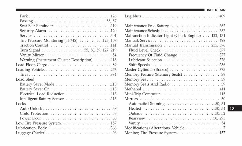
Park . . . . . . . . . . . . . . . . . . . . . . . . . . . . . . . . . .126Passing . . . . . . . . . . . . . . . . . . . . . . . . . . . . . .55, 57Seat Belt Reminder . . . . . . . . . . . . . . . . . . . . . . .119Security Alarm . . . . . . . . . . . . . . . . . . . . . . . . . .120Service . . . . . . . . . . . . . . . . . . . . . . . . . . . . . . . .301Tire Pressure Monitoring (TPMS) . . . . . . . . . .123, 157Traction Control . . . . . . . . . . . . . . . . . . . . . . . . .141Turn Signal . . . . . . . . . . . . . . . . . .55, 56, 59, 127, 219Vanity Mirror . . . . . . . . . . . . . . . . . . . . . . . . . . . .54Warning (Instrument Cluster Description) . . . . . . .118
Load Floor, Cargo . . . . . . . . . . . . . . . . . . . . . . . . . . .89Loading Vehicle. . . . . . . . . . . . . . . . . . . . . . . . . . . .276
Tires . . . . . . . . . . . . . . . . . . . . . . . . . . . . . . . . . .384Load Shed
Battery Saver Mode . . . . . . . . . . . . . . . . . . . . . . .113Battery Saver On . . . . . . . . . . . . . . . . . . . . . . . . .113Electrical Load Reduction . . . . . . . . . . . . . . . . . . .113Intelligent Battery Sensor . . . . . . . . . . . . . . . . . . .113
LocksAuto Unlock . . . . . . . . . . . . . . . . . . . . . . . . . . . . .38Child Protection . . . . . . . . . . . . . . . . . . . . . . . . . .38Power Door . . . . . . . . . . . . . . . . . . . . . . . . . . . . .33
Low Tire Pressure System. . . . . . . . . . . . . . . . . . . . .157Lubrication, Body . . . . . . . . . . . . . . . . . . . . . . . . . .366Luggage Carrier . . . . . . . . . . . . . . . . . . . . . . . . . . . .96
Lug Nuts . . . . . . . . . . . . . . . . . . . . . . . . . . . . . . . .409
Maintenance Free Battery . . . . . . . . . . . . . . . . . . . . .362Maintenance Schedule . . . . . . . . . . . . . . . . . . . . . . .357Malfunction Indicator Light (Check Engine) . . . .122, 131Manual, Service. . . . . . . . . . . . . . . . . . . . . . . . . . . .498Manual Transmission . . . . . . . . . . . . . . . . . . . .235, 376
Fluid Level Check . . . . . . . . . . . . . . . . . . . . . . . .377Frequency Of Fluid Change . . . . . . . . . . . . . . . . .377Lubricant Selection . . . . . . . . . . . . . . . . . . . . . . .376Shift Speeds . . . . . . . . . . . . . . . . . . . . . . . . . . . .236
Master Cylinder (Brakes) . . . . . . . . . . . . . . . . . . . . .375Memory Feature (Memory Seats) . . . . . . . . . . . . . . . .39Memory Seat . . . . . . . . . . . . . . . . . . . . . . . . . . . . . .39Memory Seats And Radio . . . . . . . . . . . . . . . . . . . . .39Methanol . . . . . . . . . . . . . . . . . . . . . . . . . . . . . . . .411Mini-Trip Computer. . . . . . . . . . . . . . . . . . . . . . . . .115Mirrors . . . . . . . . . . . . . . . . . . . . . . . . . . . . . . . . . .50
Automatic Dimming . . . . . . . . . . . . . . . . . . . .50, 51Heated . . . . . . . . . . . . . . . . . . . . . . . . . . . . . .50, 54Outside . . . . . . . . . . . . . . . . . . . . . . . . . . . . . .50, 52Rearview . . . . . . . . . . . . . . . . . . . . . . . . . . . .50, 295Vanity . . . . . . . . . . . . . . . . . . . . . . . . . . . . . . . . .54
Modifications/Alterations, Vehicle . . . . . . . . . . . . . . . .7Monitor, Tire Pressure System. . . . . . . . . . . . . . . . . .157
12
INDEX 507

Mopar Parts . . . . . . . . . . . . . . . . . . . . . . . . . . . . . .497Multi-Function Control Lever . . . . . . . . . . . . . . . .55, 56
New Vehicle Break-In Period . . . . . . . . . . . . . . . . . .229
Occupant Restraints . . . . . . . . . . . . . . . . . . . . . . . . .165Octane Rating, Gasoline (Fuel) . . . . . . . . . . . . . .410, 415Oil, Engine . . . . . . . . . . . . . . . . . . . . . . . . . . . .363, 415
Capacity . . . . . . . . . . . . . . . . . . . . . . . . . . . . . . .414Change Interval . . . . . . . . . . . . . . . . . . . . . . . . .363Checking . . . . . . . . . . . . . . . . . . . . . . . . . . . . . .361Dipstick . . . . . . . . . . . . . . . . . . . . . . . . . . . . . . .361Disposal . . . . . . . . . . . . . . . . . . . . . . . . . . . . . . .364Filter . . . . . . . . . . . . . . . . . . . . . . . . . . . . . .364, 415Filter Disposal . . . . . . . . . . . . . . . . . . . . . . . . . . .364Identification Logo . . . . . . . . . . . . . . . . . . . . . . .363Materials Added To . . . . . . . . . . . . . . . . . . . . . . .364Pressure Warning Light . . . . . . . . . . . . . . . . . . . .119Recommendation . . . . . . . . . . . . . . . . . . . . .363, 414Synthetic . . . . . . . . . . . . . . . . . . . . . . . . . . . . . .364Viscosity . . . . . . . . . . . . . . . . . . . . . . . . . . .363, 414
Oil Filter, Change . . . . . . . . . . . . . . . . . . . . . . . . . .364Oil Filter, Selection. . . . . . . . . . . . . . . . . . . . . . . . . .364Oil Pressure Light . . . . . . . . . . . . . . . . . . . . . . . . . .119Onboard Diagnostic System . . . . . . . . . . . . . . . . . . .129
Operating Precautions . . . . . . . . . . . . . . . . . . . . . . .129Operator Manual (Owner’s Manual) . . . . . . . . . . . . . . .5Outside Rearview Mirrors. . . . . . . . . . . . . . . . . . .50, 52Overheating, Engine . . . . . . . . . . . . . . . . . . . . . . . .346Owner’s Manual (Operator Manual) . . . . . . . . . . .5, 498
Paddle Shifters . . . . . . . . . . . . . . . . . . . . . . . . . . . .245Paint Care. . . . . . . . . . . . . . . . . . . . . . . . . . . . . . . .401Parking Brake . . . . . . . . . . . . . . . . . . . . . . . . . . . . .230ParkSense System, Rear . . . . . . . . . . . . . . . . . . . . . .259Pets . . . . . . . . . . . . . . . . . . . . . . . . . . . . . . . . . . . .215Placard, Tire And Loading Information . . . . . . . . . . .384Power
Door Locks . . . . . . . . . . . . . . . . . . . . . . . . . . . . . .33Inverter . . . . . . . . . . . . . . . . . . . . . . . . . . . . . . . .96Lift Gate . . . . . . . . . . . . . . . . . . . . . . . . . . . . . . .87Outlet (Auxiliary Electrical Outlet) . . . . . . . . . . . . .93Sunroof . . . . . . . . . . . . . . . . . . . . . . . . . . . . . . . .81Windows . . . . . . . . . . . . . . . . . . . . . . . . . . . . . . .78
Pregnant Women And Seat Belts . . . . . . . . . . . . . . . .177Preparation For Jacking . . . . . . . . . . . . . . . . . . . . . .326Pretensioners
Seat Belts . . . . . . . . . . . . . . . . . . . . . . . . . . . . . .177
Radial Ply Tires . . . . . . . . . . . . . . . . . . . . . . . . . . . .390
508 INDEX

Radiator Cap (Coolant Pressure Cap). . . . . . . . . . . . .373Radio Frequency
General Information . . . . . . . . . . . . . . . . . .24, 29, 31Radio Operation . . . . . . . . . . . . . . . . . . . . . . . . . . .470Radio Remote Controls . . . . . . . . . . . . . . . . . . . . . .469Rain Sensitive Wiper System . . . . . . . . . . . . . . . . . . .63Rear Camera . . . . . . . . . . . . . . . . . . . . . . . . . . . . . .273Rear Cross Path. . . . . . . . . . . . . . . . . . . . . . . . . . . .152Rear ParkSense System . . . . . . . . . . . . . . . . . . . . . .259Rear Seat, Folding . . . . . . . . . . . . . . . . . . . . . . . . . . .44Rear Seats, Folding . . . . . . . . . . . . . . . . . . . . . . . . . .39Rear Wiper/Washer. . . . . . . . . . . . . . . . . . . . . . . . . .64Recreational Towing. . . . . . . . . . . . . . . . . . . . . . . . .286Reformulated Gasoline . . . . . . . . . . . . . . . . . . . . . . .411Refrigerant . . . . . . . . . . . . . . . . . . . . . . . . . . . . . . .366Release, Hood. . . . . . . . . . . . . . . . . . . . . . . . . . . . . .84Reminder, Lights On . . . . . . . . . . . . . . . . . . . . . .55, 58Reminder, Seat Belt . . . . . . . . . . . . . . . . . . . . . . . . .167Remote Keyless Entry
Arm The Alarm . . . . . . . . . . . . . . . . . . . . . . . . . .32Disarm The Alarm . . . . . . . . . . . . . . . . . . . . . . . .32Programming Additional Key Fobs . . . . . . . . . .23, 31
Remote Sound System (Radio) Controls . . . . . . . . . . .469Remote Starting
Exit Remote Start Mode . . . . . . . . . . . . . . . . . . . . .28
Uconnect Customer Programmable Features . . . . . .29Uconnect Settings . . . . . . . . . . . . . . . . . . . . . . . . .29
Replacement Keys . . . . . . . . . . . . . . . . . . . . . . . .23, 30Replacement Tires . . . . . . . . . . . . . . . . . . . . . . . . . .392Reporting Safety Defects . . . . . . . . . . . . . . . . . . . . .497Restraints, Child . . . . . . . . . . . . . . . . . . . . . . . . . . .200Restraints, Head . . . . . . . . . . . . . . . . . . . . . . . . . . . .46Roll Over Warning . . . . . . . . . . . . . . . . . . . . . . . . . . .4Roof Type Carrier . . . . . . . . . . . . . . . . . . . . . . . . . . .96Rotation, Tires . . . . . . . . . . . . . . . . . . . . . . . . . . . . .397
Safety Checks Inside Vehicle . . . . . . . . . . . . . . . . . . .216Safety Checks Outside Vehicle . . . . . . . . . . . . . . . . .218Safety Defects, Reporting . . . . . . . . . . . . . . . . . . . . .497Safety, Exhaust Gas . . . . . . . . . . . . . . . . . . . . . . . . .216Safety Information, Tire . . . . . . . . . . . . . . . . . . . . . .378Safety Tips . . . . . . . . . . . . . . . . . . . . . . . . . . . . . . .215Schedule, Maintenance. . . . . . . . . . . . . . . . . . . . . . .357Seat Belt
Adjustable Upper Shoulder Belt Anchorage . . . . . .172Energy Management Feature . . . . . . . . . . . . . . . .177Lap/Shoulder Belt Operation . . . . . . . . . . . . . . . .170Lap/Shoulder Belts . . . . . . . . . . . . . . . . . . . . . . .168Pregnant Women . . . . . . . . . . . . . . . . . . . . . . . . .177Seat Belt Extender . . . . . . . . . . . . . . . . . . . . . . . .176
12
INDEX 509

Seat Belt Pretensioner . . . . . . . . . . . . . . . . . . . . .177Seat Belt Reminder . . . . . . . . . . . . . . . . . . . . . . .167
Seat Belt Maintenance . . . . . . . . . . . . . . . . . . . . . . .405Seat Belt Reminder . . . . . . . . . . . . . . . . . . . . . . . . .167Seat Belts . . . . . . . . . . . . . . . . . . . . . . . . . . . . .166, 216
Adjustable Shoulder Belt . . . . . . . . . . . . . . . . . . .172Adjustable Upper Shoulder Anchorage . . . . . . . . .172Child Restraints . . . . . . . . . . . . . . . . . . . . . . . . .200Extender . . . . . . . . . . . . . . . . . . . . . . . . . . . . . . .176Front Seat . . . . . . . . . . . . . . . . . . . . . . .166, 168, 170Inspection . . . . . . . . . . . . . . . . . . . . . . . . . . . . . .216Lap/Shoulder Belt Untwisting . . . . . . . . . . . . . . .172Operating Instructions . . . . . . . . . . . . . . . . . . . . .170Pregnant Women . . . . . . . . . . . . . . . . . . . . . . . . .177Pretensioners . . . . . . . . . . . . . . . . . . . . . . . . . . .177Rear Seat . . . . . . . . . . . . . . . . . . . . . . . . . . . . . .168Reminder . . . . . . . . . . . . . . . . . . . . . . . . . . . . . .119Untwisting Procedure . . . . . . . . . . . . . . . . . . . . .172
Seats . . . . . . . . . . . . . . . . . . . . . . . . . . . . . . . . . .39, 43Adjustment . . . . . . . . . . . . . . . . . . . . . . . . . . . . .39Easy Entry . . . . . . . . . . . . . . . . . . . . . . . . . . . . . .39Head Restraints . . . . . . . . . . . . . . . . . . . . . . . . . .46Heated . . . . . . . . . . . . . . . . . . . . . . . . . . . . . .39, 43Memory . . . . . . . . . . . . . . . . . . . . . . . . . . . . . . . .39Rear Folding . . . . . . . . . . . . . . . . . . . . . . . . . .39, 44
Seatback Release . . . . . . . . . . . . . . . . . .39, 40, 41, 44Tilting . . . . . . . . . . . . . . . . . . . . . . . . . . . . . . .39, 40Vented . . . . . . . . . . . . . . . . . . . . . . . . . . . . . . . . .39Ventilated . . . . . . . . . . . . . . . . . . . . . . . . . . . . . . .39
Security Alarm . . . . . . . . . . . . . . . . . . . . . . . . . .31, 120Arm The System . . . . . . . . . . . . . . . . . . . . . . . . . .32Disarm The System . . . . . . . . . . . . . . . . . . . . . . . .32
Selection Of Coolant (Antifreeze) . . . . . . . . . . . . . . .415Sentry Key
Key Programming . . . . . . . . . . . . . . . . . . . . . . . . .31Sentry Key Replacement . . . . . . . . . . . . . . . . . . . .23, 30Service Assistance . . . . . . . . . . . . . . . . . . . . . . . . . .494Service Contract . . . . . . . . . . . . . . . . . . . . . . . . . . .496Service Manuals . . . . . . . . . . . . . . . . . . . . . . . . . . .498Shifting
Automatic Transmission . . . . . . . . . . . . . . . . . . . .241Manual Transmission . . . . . . . . . . . . . . . . . . . . . .235
Shift Lever Override . . . . . . . . . . . . . . . . . . . . . . . .347Shoulder Belts . . . . . . . . . . . . . . . . . . . . . . . . . . . . .168Side View Mirror Adjustment . . . . . . . . . . . . . . . .50, 52Signals, Turn . . . . . . . . . . . . . . . . . . . . .55, 59, 127, 219Siri. . . . . . . . . . . . . . . . . . . . . . . . . . . . . . . . . . . . .486SiriusXM Guardian
Vehicle Health Alert . . . . . . . . . . . . . . . . . . . . . . .485Snow Chains (Tire Chains) . . . . . . . . . . . . . . . . . . . .396
510 INDEX
Snow Tires . . . . . . . . . . . . . . . . . . . . . . . . . . . . . . .394Spare Tire . . . . . . . . . . . . . . . . . . . . . . . . . . . . . . . .394Spare Tires . . . . . . . . . . . . . . . . . . . . . . . . . . . .395, 396Spark Plugs . . . . . . . . . . . . . . . . . . . . . . . . . . . . . .415Specifications
Fuel (Gasoline) . . . . . . . . . . . . . . . . . . . . . . . . . .415Oil . . . . . . . . . . . . . . . . . . . . . . . . . . . . . . . . . . .415
Speed ControlAccel/Decel . . . . . . . . . . . . . . . . . . . . . . . . . . . .259Cancel . . . . . . . . . . . . . . . . . . . . . . . . . . . . . . . .259Resume . . . . . . . . . . . . . . . . . . . . . . . . . . . . . . .259
Speed Control (Cruise Control) . . . . . . . . . . . . . . . . .256Starting . . . . . . . . . . . . . . . . . . . . . . . . . . . . . . . . .224
Automatic Transmission . . . . . . . . . . . . . . . . . . . .224Cold Weather . . . . . . . . . . . . . . . . . . . . . . . . . . .226Engine Fails To Start . . . . . . . . . . . . . . . . . . . . . .227
Starting And Operating . . . . . . . . . . . . . . . . . . . . . .224Starting Procedures . . . . . . . . . . . . . . . . . . . . . . . . .224Steering
Column Controls . . . . . . . . . . . . . . . . . . . . . . .55, 56Tilt Column . . . . . . . . . . . . . . . . . . . . . . . . . . . . .49Wheel, Heated . . . . . . . . . . . . . . . . . . . . . . . . . . .49Wheel, Tilt . . . . . . . . . . . . . . . . . . . . . . . . . . . . . .49
Steering Wheel Audio Controls . . . . . . . . . . . . . . . . .469Steering Wheel Mounted Sound System Controls . . . .469
Storage, Vehicle. . . . . . . . . . . . . . . . . . . . . . . . . . . . .77Stuck, Freeing . . . . . . . . . . . . . . . . . . . . . . . . . . . . .348Sun Roof . . . . . . . . . . . . . . . . . . . . . . . . . . . . . . . . .81Sun Visor Extension . . . . . . . . . . . . . . . . . . . . . . . . .55Supplemental Restraint System - Air Bag . . . . . . . . . .181Sway Control, Trailer . . . . . . . . . . . . . . . . . . . . . . . .146Synthetic Engine Oil . . . . . . . . . . . . . . . . . . . . . . . .364
Telescoping Steering Column . . . . . . . . . . . . . . . . . . .49Temperature Control, Automatic (ATC) . . . . . . . . . . . .75Tie Down Hooks, Cargo . . . . . . . . . . . . . . . . . . . .89, 91Tilt Steering Column . . . . . . . . . . . . . . . . . . . . . . . . .49Time Delay, Headlight . . . . . . . . . . . . . . . . . . . . .55, 57Tire And Loading Information Placard. . . . . . . . . . . .384Tire Markings . . . . . . . . . . . . . . . . . . . . . . . . . . . . .379Tires . . . . . . . . . . . . . . . . . . . . . .218, 387, 394, 395, 399
Aging (Life Of Tires) . . . . . . . . . . . . . . . . . . . . . .392Air Pressure . . . . . . . . . . . . . . . . . . . . . . . . . . . .387Chains . . . . . . . . . . . . . . . . . . . . . . . . . . . . . . . .396Changing . . . . . . . . . . . . . . . . . . . . . . . . . . .324, 378Compact Spare . . . . . . . . . . . . . . . . . . . . . . . . . .395General Information . . . . . . . . . . . . . . . .387, 394, 395High Speed . . . . . . . . . . . . . . . . . . . . . . . . . . . . .389Inflation Pressure . . . . . . . . . . . . . . . . . . . . . . . .389Jacking . . . . . . . . . . . . . . . . . . . . . . . . . . . .324, 378
12
INDEX 511

Life Of Tires . . . . . . . . . . . . . . . . . . . . . . . . . . . .392Load Capacity . . . . . . . . . . . . . . . . . . . . . . .384, 385Pressure Monitoring System (TPMS) . . . . . . . . . . .123Pressure Monitor System (TPMS) . . . . . . . . . . . . .157Quality Grading . . . . . . . . . . . . . . . . . . . . . . . . .399Radial . . . . . . . . . . . . . . . . . . . . . . . . . . . . . . . .390Replacement . . . . . . . . . . . . . . . . . . . . . . . . . . . .392Rotation . . . . . . . . . . . . . . . . . . . . . . . . . . . . . . .397Safety . . . . . . . . . . . . . . . . . . . . . . . . . . . . .378, 387Sizes . . . . . . . . . . . . . . . . . . . . . . . . . . . . . . . . .380Snow Tires . . . . . . . . . . . . . . . . . . . . . . . . . . . . .394Spare Tire . . . . . . . . . . . . . . . . . . . . . . . . . . . . . .394Spare Tires . . . . . . . . . . . . . . . . . . . . . . . . . .395, 396Spinning . . . . . . . . . . . . . . . . . . . . . . . . . . . . . . .391Trailer Towing . . . . . . . . . . . . . . . . . . . . . . . . . . .282Tread Wear Indicators . . . . . . . . . . . . . . . . . . . . .391Wheel Nut Torque . . . . . . . . . . . . . . . . . . . . . . . .409
Tire Safety Information. . . . . . . . . . . . . . . . . . . . . . .378Tire Service Kit . . . . . . . . . . . . . . . . . . . . . . . . . . . .332Tongue Weight/Trailer Weight . . . . . . . . . . . . . . . . .281To Open Hood . . . . . . . . . . . . . . . . . . . . . . . . . . . . .84Tow Hooks, Emergency . . . . . . . . . . . . . . . . . . . . . .352Towing . . . . . . . . . . . . . . . . . . . . . . . . . . . . . . . . . .278
Disabled Vehicle . . . . . . . . . . . . . . . . . . . . . . . . .349Guide . . . . . . . . . . . . . . . . . . . . . . . . . . . . . . . . .280
Recreational . . . . . . . . . . . . . . . . . . . . . . . . . . . .286Weight . . . . . . . . . . . . . . . . . . . . . . . . . . . . . . . .280
Towing Vehicle Behind A Motorhome . . . . . . . . . . . .286Traction Control . . . . . . . . . . . . . . . . . . . . . . . . . . .135Trailer Sway Control (TSC) . . . . . . . . . . . . . . . . . . . .146Trailer Towing. . . . . . . . . . . . . . . . . . . . . . . . . . . . .278
Cooling System Tips . . . . . . . . . . . . . . . . . . . . . .286Minimum Requirements . . . . . . . . . . . . . . . . . . . .281Tips . . . . . . . . . . . . . . . . . . . . . . . . . . . . . . . . . .285Trailer And Tongue Weight . . . . . . . . . . . . . . . . . .281Wiring . . . . . . . . . . . . . . . . . . . . . . . . . . . . . . . .283
Trailer Towing Guide . . . . . . . . . . . . . . . . . . . . . . . .280Trailer Weight . . . . . . . . . . . . . . . . . . . . . . . . . . . . .280Transaxle . . . . . . . . . . . . . . . . . . . . . . . . . . . . . . . .239
Automatic . . . . . . . . . . . . . . . . . . . . . . . . . . . . .239Operation . . . . . . . . . . . . . . . . . . . . . . . . . . . . . .239
Transfer CaseFluid . . . . . . . . . . . . . . . . . . . . . . . . . . . . . . . . .416
Transmission . . . . . . . . . . . . . . . . . . . . . . . . . . . . . .241Automatic . . . . . . . . . . . . . . . . . . . . . . . . . .241, 377Fluid . . . . . . . . . . . . . . . . . . . . . . . . . . . . . . . . .416Maintenance . . . . . . . . . . . . . . . . . . . . . . . . . . . .377Manual . . . . . . . . . . . . . . . . . . . . . . . . . . . . . . . .235
Transporting Pets . . . . . . . . . . . . . . . . . . . . . . . . . .215Tread Wear Indicators . . . . . . . . . . . . . . . . . . . . . . .391
512 INDEX

Turn Signals . . . . . . . . . . . . . . . . . . . . . . . . .55, 59, 127
UCI Connector . . . . . . . . . . . . . . . . . . . . . . . . . . . .470Uconnect
Customer Programmable Features . . . . . . . . . . . . .29Uconnect Settings . . . . . . . . . . . . . . . . . . . . . . . . .29
Uconnect Voice Command . . . . . . . . . . . . . . . . . . . .472Uniform Tire Quality Grades . . . . . . . . . . . . . . . . . .399Universal Consumer Interface (UCI) Connector . . . . .470Untwisting Procedure, Seat Belt . . . . . . . . . . . . . . . .172
Vanity Mirrors . . . . . . . . . . . . . . . . . . . . . . . . . . . . .54Vehicle Identification Number (VIN) . . . . . . . . . . . . .408Vehicle Loading . . . . . . . . . . . . . . . . . . . . . . . .276, 385Vehicle Modifications/Alterations. . . . . . . . . . . . . . . . .7Vehicle Security Alarm (Security Alarm) . . . . . . . . . . .31Vehicle Storage . . . . . . . . . . . . . . . . . . . . . . . . . . . . .77Viscosity, Engine Oil . . . . . . . . . . . . . . . . . . . . . . . .363Voice Recognition System (VR). . . . . . . . . . . . . .472, 487
Warning Flasher, Hazard . . . . . . . . . . . . . . . . . . . . .295Warning Lights (Instrument Cluster Descriptions). . . .121Warning, Roll Over . . . . . . . . . . . . . . . . . . . . . . . . . . .4Warnings And Cautions . . . . . . . . . . . . . . . . . . . . . . .7Warranty Information . . . . . . . . . . . . . . . . . . . . . . .497
Washers, Windshield. . . . . . . . . . . . . . . . . . . . . .61, 361Washing Vehicle . . . . . . . . . . . . . . . . . . . . . . . . . . .403Wheel And Wheel Tire Care . . . . . . . . . . . . . . . . . . .401Wheel And Wheel Tire Trim . . . . . . . . . . . . . . . . . . .401Wind Buffeting . . . . . . . . . . . . . . . . . . . . . . . . . .80, 84Window Fogging . . . . . . . . . . . . . . . . . . . . . . . . . . .77Windows . . . . . . . . . . . . . . . . . . . . . . . . . . . . . . . . .78
Close . . . . . . . . . . . . . . . . . . . . . . . . . . . . . . . . . .78Down . . . . . . . . . . . . . . . . . . . . . . . . . . . . . . . . .78Open . . . . . . . . . . . . . . . . . . . . . . . . . . . . . . . . . .78Power . . . . . . . . . . . . . . . . . . . . . . . . . . . . . . . . .78Up . . . . . . . . . . . . . . . . . . . . . . . . . . . . . . . . . . . .78
Windshield Defroster . . . . . . . . . . . . . . . . . . . . . . . .217Windshield Washers . . . . . . . . . . . . . . . . . . . . . .61, 361
Fluid . . . . . . . . . . . . . . . . . . . . . . . . . . . . . . . . .361Windshield Wiper Blades . . . . . . . . . . . . . . . . . . . . .366Windshield Wipers . . . . . . . . . . . . . . . . . . . . . . . . . .61Wiper Blade Replacement. . . . . . . . . . . . . . . . . . . . .366Wipers, Rain Sensitive . . . . . . . . . . . . . . . . . . . . . . .63
12
INDEX 513


VEHICLES SOLD IN CANADAWith respect to any Vehicles Sold in Canada, the nameFCA US LLC shall be deemed to be deleted and the nameFCA Canada Inc. used in substitution therefore.
DRIVING AND ALCOHOLDrunken driving is one of the most frequent causes ofaccidents.Your driving ability can be seriously impaired with bloodalcohol levels far below the legal minimum. If you aredrinking, don’t drive. Ride with a designated non-drinking driver, call a cab, a friend, or use public trans-portation.
WARNING!
Driving after drinking can lead to an accident.Your perceptions are less sharp, your reflexes areslower, and your judgment is impaired when youhave been drinking. Never drink and then drive.
This manual illustrates and describes the operation offeatures and equipment that are either standard or op-tional on this vehicle. This manual may also include adescription of features and equipment that are no longeravailable or were not ordered on this vehicle. Pleasedisregard any features and equipment described in thismanual that are not on this vehicle.
FCA US LLC reserves the right to make changes in designand specifications, and/or make additions to or improve-ments to its products without imposing any obligationupon itself to install them on products previously manu-factured.
Copyright © 2018 FCA US LLC
INSTALLATION OF RADIO TRANSMITTINGEQUIPMENTSpecial design considerations are incorporated into thisvehicle’s electronic system to provide immunity to radiofrequency signals. Mobile two-way radios and telephoneequipment must be installed properly by trained person-nel. The following must be observed during installation.
The positive power connection should be made directlyto the battery and fused as close to the battery as possible.The negative power connection should be made to bodysheet metal adjacent to the negative battery connection.This connection should not be fused.
Antennas for two-way radios should be mounted on theroof or the rear area of the vehicle. Care should be usedin mounting antennas with magnet bases. Magnets mayaffect the accuracy or operation of the compass onvehicles so equipped.
The antenna cable should be as short as practical androuted away from the vehicle wiring when possible. Useonly fully shielded coaxial cable.
Carefully match the antenna and cable to the radio toensure a low Standing Wave Ratio (SWR).
Mobile radio equipment with output power greater thannormal may require special precautions.
All installations should be checked for possible interfer-ence between the communications equipment and thevehicle’s electronic systems.
WARNING:
Operating, servicing and maintaining apassenger vehicle or off-road highwaymotor vehicle can expose you to chemicalsincluding engine exhaust, carbon monoxide,phthalates, and lead, which are known tothe State of California to cause cancer andbirth defects or other reproductive harm.To minimize exposure, avoid breathingexhaust, do not idle the engine except asnecessary, service your vehicle in awell-ventilated area and wear gloves orwash your hands frequently when servicingyour vehicle. For more information go towww.P65Warnings.ca.gov/passenger-vehicle.
DID_3636116_18d_Jeep_Compass_OM_070518.indd 2 7/5/2018 9:36:51 PM

CompassOW N E R ’ S M A N UA L
V2Fourth Edition Printed in the U.S.A.
18_MP_OM_EN_USC©2021 FCA US LLC. All Rights Reserved. Jeep is a registered trademark of FCA US LLC.
2 0 1 8
Co
mp
ass
20
18
DID_3636116_18d_Jeep_Compass_OM_070518.indd 1 7/5/2018 9:36:43 PM