p1394.3 draft 1 - pwg.org · device and service discovery, self ... authroization request ... by...
TRANSCRIPT

Copyright © 2000 by the Institute of Electrical And Electronics Engineers, Inc345 East 47th Street,New York, NY 10017, USAAll rights reserved
This is an unapproved IEEE Standards Project, subject to change. Permission is hereby granted for IEEE Standards Committeeparticipants to reproduce this document for purposes of IEEE standardization activities, including balloting and coordination. If thisdocument is to be submitted to ISO or IEC, notification shall be given to the IEEE Copyrights Administrator. Permission is alsogranted for member bodies and technical committees of ISO and IEC to reproduce this document for purposes of developing anational position. Other entities seeking permission to reproduce this document for these or other uses must contact the IEEEStandards Department for the appropriate license. Use of the information contained in this unapproved draft is at your own risk.
IEEE Standards DepartmentCopyrights and Permissions445 Hoes Lane, PO Box 1331Piscataway, NJ 08855-1333, USA
P1394.3 Draft 1.2June 26, 2000
P1394.3Draft Standard for aHigh Performance Serial BusPeer-to-Peer Data Transport Protocol (PPDT)
Sponsor
Microprocessor and Microcomputer Standards Committeeof theIEEE Computer Society
Not yet approved by
IEEE-SA Standards Board
Not yet approved by
American National Standards Institute
Abstract: This standard defines a peer-to-peer data transport (PPDT) protocol between Serial Busdevices that implement ANSI NCITS 325-1998, Serial Bus Protocol 2. The facilities specified includedevice and service discovery, self-configurable (plug and play) binding, and connection management.
Keywords: computers, CSR architecture, connect, peer-to-peer, SBP-2, transport protocol

PPDT P1394.3 Draft 1.2June 26, 2000
Copyright © 2000 IEEE. All rights reservedThis is an unapproved IEEE Standards Draft, subject to change.
ii
IEEE Standards documents are developed within the IEEE Societies and the Standards CoordinatingCommittees of the IEEE Standards Board. Members of the committees serve voluntarily and withoutcompensation. They are not necessarily members of the Institute. The standards developed within IEEErepresent a consensus of the broad expertise on the subject within the Institute as well as those activitiesoutside of IEEE that have expressed an interest in participating in the development of the standard.
Use of an IEEE Standard is wholly voluntary. The existence of an IEEE Standard does not imply that thereare no other ways to produce, test, measure, purchase, market, or provide other goods and servicesrelated to the scope of the IEEE Standard. Furthermore, the viewpoint expressed at the time a standard isapproved and issued is subject to change brought about through developments in the state of the art andcomments received from users of the standard. Every IEEE Standard is subjected to review at least everyfive years for revision or reaffirmation. When a document is more than five years old and has not beenreaffirmed, it is reasonable to conclude that its contents, although still of some value, do not wholly reflectthe present state of the art. Users are cautioned to check to determine that they have the latest edition ofany IEEE Standard.
Comments for revision of IEEE Standards are welcome from any interested party, regardless ofmembership affiliation with IEEE. Suggestions for changes in documents should be in the form of aproposed change of text, together with appropriate supporting comments.
Interpretations: Occasionally questions may arise regarding the meaning of portions of standards as theyrelate to specific applications. When the need for interpretations is brought to the attention of IEEE, theInstitute will initiate action to prepare appropriate responses. Since IEEE Standards represent aconsensus of all concerned interests, it is important to ensure that any interpretation has also received theconcurrence of a balance of interests. For this reason, IEEE and the members of its societies andStandards Coordinating Committees are not able to provide an instant response to interpretation requestsexcept in those cases where the matter has previously received formal consideration.
Comments on standards and requests for interpretations should be addressed to:
Secretary, IEEE Standards Board445 Hoes LanePO Box 1331Piscataway, NJ 08855-1331USA

P1394.3 Draft 1.2 PPDTJune 26, 2000
Copyright © 2000 IEEE. All rights reservedThis is an unapproved IEEE Standards Draft, subject to change.
iii
Introduction
(This introduction is not part of the draft standard, IEEE P1394.3, Standard for a High Performance SerialBus Peer-to-Peer Data Transport Protocol)
The IEEE approved project P1394.3 on January 30, 2000, at the request of Gregory LeClair, then Chair ofthe 1394 Printer Working Group, an informal industry consortium. Although final approval of this standardhas taken place under the aegis of the IEEE, most of the significant effort occurred prior to the formationof the P1394.3 working group.
The necessity for a Serial Bus transport protocol for printers and similar devices was first broached inhallway conversation at the quarterly meeting of the 1394 Trade Association in Redmond, WA, in October,1996. This lead to a “birds of a feather” assembly hosted at Adobe Systems in San Jose, CA, onDecember 6 that same year. The attendees at this crowded gathering discussed the suitability of exisitingprotocols, particulary SBP-2, and the venue for the proposed standards work. The group concluded thatno existing protocol suited their needs: one would have to be developed. Don Wright offered the servicesof the Printer Working Group, an ad hoc industry forum whose principal participants are printer vendors,and Greg LeClair wrote the initial charter for the group.
The first official meeting of the 1394 Printer Working Group was held in Albuquerque, NM, early in 1997.Consensus was quickly reached that the new protocol must be friendly to legacy data formats; thisexposed the two major areas that occupied the working group for the next three years: a) device discoveryand enumeration and b) a data transport protocol.
The working group examined the facilities of IEEE Std 1394-1995 and the CSR architecture andconcluded that configuration ROM might permit practical solutions for device discovery but that the currentstandard, ISO/IEC 13213:1994, did not adequately specify the necessary building blocks. The 1394 PrinterWorking Group applied to the IEEE Microprocessor and Microcomputer Standards for a projectauthroization request (PAR) to commence new work. Simultaneously, the CSR architecture was due forrevision and the MMSC approved a PAR for IEEE P1212 and suggested to the 1394 Printer WorkingGroup that work be transferred to the IEEE. In fact, many participants became simultaneously active in theIEEE P1212 working group and provided strong continuity between the two complementary efforts. At thetime of writing, draft standard IEEE P1212 is in the ballot process and is likely to be an approved standardby the end of 2000.
With work on device discovery split off to IEEE P1212, the 1394 Printer Working Group was free to focusits efforts on the transport protocol. There were two principal candidates, SBP-2 and the “thin” protocoljointly developed by camera and printer companies in Japan. No matter which protocol (or adaptationthereof) was ultimately chosen, the 1394 PWG thought it was important to recognize the peer-to-peernature of the desired operating environment. The working group concluded that a solution similar to the“sockets” API that supported confirmed, efficient bi-directional data delivery between peers would suit theirneeds. Close to a year was spent debating the pros and cons of different approaches. In the end, thegroup converged on ANSI NCITS 325-1998 as the underlying mechanism: the 1394 PWG would focus itsefforts on enhancements to SBP-2 to render it more fully peer-to-peer.
Once the selection of an underlying protocol was agreed, work progressed fairly quickly on what waseventually dubbed PPDT: peer-to-peer data transport protocol. The prototype efforts expended by someearly adopters, both in Japan and the United States have been invaluable in the resolution of detailedtechnical questions that arose as this document was refined. In particular, the essential mechanisms firstproposed as the Simple High Performance Transport (SHPT) were ultimately adopted. SHPT tookadvantage of the SBP-2 unordered execution model to provide independent, bi-directional data transportwithin the context of a single SBP-2 login. SHPT also optimized error recovery operations after bus resetby using execution context information known by both initiator and target.

PPDT P1394.3 Draft 1.2June 26, 2000
Copyright © 2000 IEEE. All rights reservedThis is an unapproved IEEE Standards Draft, subject to change.
iv
Towards the end of summer 1999 it was apparent that the work neared conclusion; at this time theworking group discussed possible homes for the draft standard and agreed upon the IEEE as the bestchoice.
Patent notice
NOTE – Attention is called to the possibility that implementation of this standard may require use of subjectmatter covered by patent rights. By publication of this standard, no position is taken with respect to theexistence or validity of any patent rights in connection therewith. The IEEE shall not be responsible foridentifying all patents for which a license may be required by an IEEE standard or for conducting inquiries intothe legal validity or scope of those patents that are brought to its attention.
The patent holder has, however, filed a statement of assurance that it will grant a license under theserights without compensation or under reasonable rates and nondiscriminatory, reasonable terms andconditions to all applicants desiring to obtain such a license. The IEEE makes no representation as to thereasonableness of rates and/or terms and conditions of the license agreement offered by the patentholder. Contact information may be obtained from the IEEE Standards Department.
Committee membership
The following is a list of active participants in the IEEE P1394.3 working group (those who attended morethan three meetings from original inception of the predecessor Printer Working Group activity to the timeof publication).
Gregory LeClair, ChairAlan Berkema, Vice ChairPeter Johansson, Editor
Lee Farrell / Larry Stein, Secretaries
Brian BatchelderAlan BerkemaScott BonarMike FenelonDoug FritzJohn FullerOsamu HirataTakashi IsodaLaurie Lasslo
Bob MorfordFumio NagasakaBrian NagyAtsushi NakamuraKazuo NomuraChuck RiceFumio SamitsuYuji SasakiHitoshi Sekine
Akihiro ShimuraNobuhiko ShinodaGreg ShueLarry SteinJerry ThrasherRandy TurnerShigeru UedaRainier WolfcastleDon Wright
The following people were members of the balloting group:
The following people served on the ballot response committee:

P1394.3 Draft 1.2 PPDTJune 26, 2000
Copyright © 2000 IEEE. All rights reservedThis is an unapproved IEEE Standards Draft, subject to change.
v
Working group points of contact
Chair: Gregory LeClairSeiko Epson Corporation150 River Oaks Pkwy., Suite 200San Jose, CA 95134
(408) 576-4145(408) 474-0511 [email protected]
Vice Chair: Alan BerkemaHewlett-Packard Company8000 Foothills Blvd., MS 5558Roseville, CA 95747-5558
(916) 785-5605(916) 785-1195 [email protected]
Editor: Peter JohanssonCongruent Software, Inc.98 Colorado AvenueBerkeley, CA 94707
(510) 527-3926(510) 527-3856 [email protected]
Secretaries: Lee FarrellCanon Information Systems110 Innovation DriveIrvine, CA 92612
(949) 856-7163(949) 856-7510 [email protected]
Larry SteinWarp Nine Engineering3645 Ruffin Rd., Suite 330San Diego, CA 92123
(858) 292-2742(858) 292-8020 [email protected]
Home page: http://www.pwg.org/p1394
Reflector: [email protected]@PWG.org (to subscribe)

PPDT P1394.3 Draft 1.2June 26, 2000
Copyright © 2000 IEEE. All rights reservedThis is an unapproved IEEE Standards Draft, subject to change.
vi
Revision history
Draft 1.1 (February 10, 2000)
First release of a document as the work product of the IEEE P1394.3 working group; it is based uponefforts to date in 1394 Printer Working Group predecessor documents.
Draft 1.2 (June 26, 2000)
Minor typographical corrections discussed by the working group on the [email protected] reflector.

P1394.3 Draft 1.2 PPDTJune 26, 2000
Copyright © 2000 IEEE. All rights reservedThis is an unapproved IEEE Standards Draft, subject to change.
vii
ContentsPage
1 Overview.....................................................................................................................................................11.1 Scope...................................................................................................................................................11.2 Purpose................................................................................................................................................1
2 Normative references .................................................................................................................................32.1 Approved references............................................................................................................................32.2 References under development...........................................................................................................32.3 Reference acquisition ..........................................................................................................................3
3 Definitions and notation ..............................................................................................................................53.1 Definitions ............................................................................................................................................5
3.1.1 Conformance definitions ...............................................................................................................53.1.2 Technical definitions ......................................................................................................................53.1.3 Abbreviations.................................................................................................................................8
3.2 Notation................................................................................................................................................83.2.1 Numeric values..............................................................................................................................93.2.2 Bit, byte and quadlet ordering........................................................................................................9
4 Model (informative)................................................................................................................................... 114.1 Protocol stack and service model ...................................................................................................... 114.2 Independent data paths for each service...........................................................................................124.3 Connection management...................................................................................................................134.4 Data transfer between initiator and target ..........................................................................................144.5 Control requests and responses ........................................................................................................154.6 Unsolicited status ...............................................................................................................................164.7 Reverse login and logout ...................................................................................................................16
5 Data structures .........................................................................................................................................195.1 Transport flow ORBs..........................................................................................................................195.2 Status block........................................................................................................................................205.3 Control information.............................................................................................................................225.4 Queue information .............................................................................................................................255.5 Reverse login request and response .................................................................................................26
6 Control operations ....................................................................................................................................296.1 Login, reverse login and queue zero..................................................................................................296.2 Autonomous response information ....................................................................................................306.3 Connection management...................................................................................................................31
6.3.1 Connection establishment ...........................................................................................................316.3.2 Queue shutdown .........................................................................................................................32
6.4 Queue status information...................................................................................................................356.5 Logout and reverse logout .................................................................................................................35
7 Transport flow operations .........................................................................................................................377.1 Data transfer to a target .....................................................................................................................387.2 Data transfer to an initiator.................................................................................................................397.3 Completion status ..............................................................................................................................407.4 Execution context for active ORBs ....................................................................................................417.5 Error recovery ....................................................................................................................................41
8 Configuration ROM...................................................................................................................................458.1 Root directory.....................................................................................................................................468.2 Instance directories............................................................................................................................47

PPDT P1394.3 Draft 1.2June 26, 2000
Copyright © 2000 IEEE. All rights reservedThis is an unapproved IEEE Standards Draft, subject to change.
viii
8.3 Feature directories .............................................................................................................................478.4 Keyword leaves..................................................................................................................................478.5 Initiator unit directory..........................................................................................................................488.6 Target unit directories.........................................................................................................................498.7 Private unit directory ..........................................................................................................................508.8 Device ID............................................................................................................................................50
Tables
Table 1 – Parameter ID values ....................................................................................................................24Table 2 – Connection type encoded by queue ID parameters.....................................................................31Table 3 – Root directory entries ...................................................................................................................46Table 4 – Feature directory entries ..............................................................................................................47Table 5 – Recommended keywords ............................................................................................................47Table 6 – Initiator unit directory entries ........................................................................................................48Table 7 – Target unit directory entries..........................................................................................................49
Figures
Figure 1 – Bit ordering within a byte ..............................................................................................................9Figure 2 – Byte ordering within a quadlet ......................................................................................................9Figure 3 – Quadlet ordering within an octlet ................................................................................................10Figure 4 – Protocol stack (service at target)................................................................................................ 11Figure 5 – Protocol stack (service at initiator) ............................................................................................. 11Figure 6 – Multiplexed queues in an SBP-2 task set ...................................................................................12Figure 7 – Independent queues (logical model) ..........................................................................................13Figure 8 – Control request originated by initiator .........................................................................................15Figure 9 – Control request originated by target ...........................................................................................16Figure 10 – Transport flow ORB..................................................................................................................19Figure 11 – Status block format ...................................................................................................................21Figure 12 – Control information format........................................................................................................22Figure 13 – Immediate parameter format....................................................................................................24Figure 14 – Variable-length parameter format.............................................................................................25Figure 15 – Queue information format ........................................................................................................25Figure 16 – Queue information byte format.................................................................................................26Figure 17 – Reverse login request / response format .................................................................................26Figure 18 – Transport flow (datagram mode) ..............................................................................................37Figure 19 – Transport flow (stream mode) ..................................................................................................37Figure 20 – Transport flow (stream mode with explicit SDUs) ....................................................................38Figure 21 – Excess initiator data (datagram mode).....................................................................................38Figure 22 – Partial data transfer (stream mode) .........................................................................................39Figure 23 – Excess target data (datagram mode) .......................................................................................40Figure 24 – Example configuration ROM hierarchy.....................................................................................45Figure 25 – First five quadlets of configuration ROM ..................................................................................45
Figure F-1 – Example bus information block and root directory..................................................................61Figure F-2 – Feature directory with service ID leaf......................................................................................62Figure F-3 – Unit directory for peer-to-peer data transport (PPDT) protocol target.....................................63Figure F-4 – Instance directory and keyword leaf for a scanner .................................................................64Figure F-5 – Instance directory and keyword leaf for a multiple protocol printer.........................................65Figure F-6 – Example MFP configuration ROM hierarchy...........................................................................66Figure F-7 – Instance directory and keyword leaf for a multifunction peripheral (MFP) ..............................67Figure F-8 – Initiator unit directory with a service ID leaf.............................................................................68

P1394.3 Draft 1.2 PPDTJune 26, 2000
Copyright © 2000 IEEE. All rights reservedThis is an unapproved IEEE Standards Draft, subject to change.
ix
Annexes
Annex A (normative) Minimum Serial Bus node capabilities ......................................................................51
Annex B (normative) Compliance with ANSI NCITS 325-1998..................................................................53
Annex C (normative) Control request and response parameters...............................................................55
Annex D (normative) Control and status registers......................................................................................57
Annex E (normative) Service ID registration ..............................................................................................59
Annex F (informative) Configuration ROM .................................................................................................61


P1394.3 Draft 1.2 PPDTJune 26, 2000
Copyright © 2000 IEEE. All rights reservedThis is an unapproved IEEE Standards Draft, subject to change.
1
1 OverviewScope and purpose
1.1 Scope
This is a full-use standard whose scope is the definition of a peer-to-peer data transport (PPDT) protocolbetween Serial Bus devices that implement ANSI NCITS 325-1998, Serial Bus Protocol 2. The facilitiesspecified include, but are not limited to, the following:
– Device and service discovery. PPDT devices may use uniform discovery procedures to locate otherPPDT devices on the same bus. These procedures are extensible to an interconnected net ofbuses, when specified by IEEE P1394.1, Draft Standard for Serial Bus to Serial Bus Bridges. Onceother PPDT devices are identified, facilities are provided to permit client applications to discoverservices;
– Self-configurable (plug and play) binding of device drivers to PPDT devices in a dynamicenvironment where users are free to insert and remove devices at will; and
– Connection management. A PPDT device (either an SBP-2 initiator or target) may establish andmanage uni- or bi-directional connections for data transfer with other PPDT devices. Theconnections may be blocking or nonblocking, dependent upon application requirements, and operateindependently of each other.
Although the original impetus for the development of this standard came from participants knowledgeableabout printers and printing, the work evolved and became relevant to any application that requiresefficient, peer-to-peer transport of data between devices.
1.2 Purpose
Experience with SBP-2 has demonstrated its high efficiency for the confirmed transport of large quantitiesof data between two devices. For historical reasons, SBP-2 is tailored to an environment where onedevice is the initiator (client) and the other the target (server); this is not necessarily the most naturalapproach when client applications and their associated servers may be located within initiator, target orboth. Because SBP-2 is already widely implemented in operating systems, this standard leverages thateffort in order to enhance the value of Serial Bus to devices in a wider range of operational circumstances.
This standard creates a new layer of protocol services based upon SBP-2 but that provides buildingblocks more suited to a peer-to-peer environment which includes printers, facsimile devices, scanners (ormultifunction devices that present some combination of these capabilities) when a computer is present—but it is also intended to address the peer-to-peer needs of devices to communicate with each other in theabsence of a computer.


P1394.3 Draft 1.2 PPDTJune 26, 2000
Copyright © 2000 IEEE. All rights reservedThis is an unapproved IEEE Standards Draft, subject to change.
3
2 Normative references
The standards named in this section contain provisions which, through reference in this text, constituteprovisions of this standard. At the time of publication, the editions indicated were valid. All standards aresubject to revision; parties to agreements based on this standard are encouraged to investigate thepossibility of applying the most recent editions of the standards indicated below.
2.1 Approved references
The following approved standards may be obtained from the international and regional organizations thatcontrol them.
ANSI NCITS 325-1998, American National Standard for Information Systems – Serial Bus Protocol 2(SBP-2)
ANSI X3.4-1986, American National Standard for Information Systems – Coded Character Sets –7-Bit American National Standard Code for Information Interchange (7-Bit ASCII)
IEEE Std 1284-1994, Standard Signaling Method for a Bi-directional Parallel Peripheral Interface forPersonal Computers
IEEE Std 1394-1995, Standard for a High Performance Serial Bus
IEEE Std 1394a-2000, Standard for a High Performance Serial Bus—Amendment 1
2.2 References under development
At the time of publication, the following referenced standards were under development.
IEEE P1212, Draft Standard for a Control and Status Register (CSR) Architecture for MicrocomputerBuses
IEEE P1394a, Draft Standard for a High Performance Serial Bus (Supplement)
2.3 Reference acquisition
The references cited in the preceding clauses may be obtained from the organizations that control them:
American National Standards Institute (ANSI), 11 West 42nd Street, New York, NY 10036, USA;(212) 642-4900 / (212) 398-0023 (FAX); http://www.ansi.org/
Institute of Electrical and Electronic Engineers (IEEE)1, 445 Hoes Lane, PO Box 1331, Piscataway,NJ 08855-1331, USA; (732) 981-0060 / (732) 981-1721 (FAX); http://www.ieee.org/
1 Standards under development are not directly available from the IEEE; interested parties who wish to review or
comment upon a draft standard may access the documents maintained by the working group. In the case of draftstandard IEEE P1394a consult ftp://ftp.t10.org/1394/P1394a/; draft standard IEEE P1212 may be downloaded fromhttp://www.zayante.com/p1212r/.

PPDT P1394.3 Draft 1.2June 26, 2000
Copyright © 2000 IEEE. All rights reservedThis is an unapproved IEEE Standards Draft, subject to change.
4
In addition, many of the documents controlled by the above organizations may also be ordered through athird party:
Global Engineering Documents, 15 Inverness Way, Englewood, CO 80112-5776; (800) 624 3974 /(303) 792-2192; http://www.global.ihs.com/

P1394.3 Draft 1.2 PPDTJune 26, 2000
Copyright © 2000 IEEE. All rights reservedThis is an unapproved IEEE Standards Draft, subject to change.
5
3 Definitions and notation
For the purposes of this standard, the following definitions, terms and notational conventions apply. IEEEStd 100-1992, The New IEEE Standard Dictionary of Electrical and Electronics Terms, should beconsulted for terms not defined in this section.
3.1 Definitions
3.1.1 Conformance definitions
Several keywords are used to differentiate levels of requirements and optionality, as follows:
3.1.1.1 expected: A keyword used to describe the behavior of the hardware or software in the designmodels assumed by this standard. Other hardware and software design models may also beimplemented.
3.1.1.2 ignored: A keyword that describes bits, bytes, quadlets, octlets or fields whose values are notchecked by the recipient.
3.1.1.3 may: A keyword that indicates flexibility of choice with no implied preference.
3.1.1.4 reserved: A keyword used to describe objects—bits, bytes, quadlets, octlets and fields—or thecode values assigned to these objects in cases where either the object or the code value is set aside forfuture standardization. Usage and interpretation may be specified by future extensions to this or otherstandards. A reserved object shall be zeroed or, upon development of a future standard, set to a valuespecified by such a standard. The recipient of a reserved object shall not check its value. The recipient ofan object defined by this standard as other than reserved shall check its value and reject reserved codevalues.
3.1.1.5 shall: A keyword that indicates a mandatory requirement. Designers are required to implement allsuch mandatory requirements to assure interoperability with other products conforming to this standard.
3.1.1.6 should: A keyword that denotes flexibility of choice with a strongly preferred alternative. Equivalentto the phrase “is recommended.”
3.1.2 Technical definitions
The following terms are used in this standard:
3.1.2.1 active ORB: From the perspective of an initiator, an operation request block (ORB) in the target'stask set, i.e., an ORB for which completion status has yet to be stored at the initiator's status_FIFO. Fromthe perspective of a target, an ORB for which the target maintains execution context.
3.1.2.2 active queue: A queue, created as part of a connection, for which target resources are allocatedand into which an initiator is permitted to post ORBs. A queue remains active from its creation until it isshutdown.
3.1.2.3 blocking connection: A bi-directional connection that utilizes a single queue for data transfer bothto and from a target. Because execution of transport flow ORBs within a queue is ordered, anuncompleted ORB for data transfer in one direction may block the execution of an ORB for data transfer inthe other direction.
3.1.2.4 byte: Eight bits of data.

PPDT P1394.3 Draft 1.2June 26, 2000
Copyright © 2000 IEEE. All rights reservedThis is an unapproved IEEE Standards Draft, subject to change.
6
3.1.2.5 connection: A queue or a pair of queue(s) that affords access to a service. A connection may beunidirectional or bi-directional; in the latter case, a connection may be blocking or nonblocking. Twoqueues are necessary to implement a bi-directional, nonblocking connection.
3.1.2.6 control information: Information exchanged between initiator and target whose format is definedby this standard. The format of control information is independent of the format of application dataexchanged by client applications and services—but both control information and application data aretransported by the same methods.
3.1.2.7 control ORB: A transport flow ORB whose queue field is zero and whose end_of_message andnotify bits are one; it is used to transfer request or response control information between initiator andtarget.
3.1.2.8 execution context: Information maintained by a target for active ORBs so that data transfer maybe resumed after a task set abort without loss of data or interruption perceivable to PPDT applicationclients or services.
3.1.2.9 final ORB: A transport flow ORB whose final and notify bits are both one. An initiator uses a finalORB to indicate to a target that no subsequent operation request blocks with the same queue value will besignaled unless the queue number is reissued by the target in a future CONNECT control request orresponse.
3.1.2.10 initiator: A node that originates SBP-2 management requests, control and transport flow ORBsand signals them to a target for processing.
3.1.2.11 logical unit: The part of a target’s unit architecture that provides access to one or more services.Targets compliant with this standard implement one logical unit with a LUN of zero.
3.1.2.12 login: The process by which an initiator obtains access to a target fetch agent. The target fetchagent and its CSRs provide a mechanism for an initiator to signal ORBs to the target.
3.1.2.13 logout: The process that permits an initiator to relinquish its use of a target fetch agent and allthe resources associated with the login.
3.1.2.14 management service: A service automatically provided by a peer unit to execute controlrequests that establish or terminate connections to other services of the peer unit. The connection to thisservice is implicitly established as the result of an SBP-2 login.
3.1.2.15 node: An addressable device attached to Serial Bus.
3.1.2.16 nonblocking connection: A bi-directional connection that utilizes two queues for data transfer toand from a target, one for each direction. Since the execution of transport flow ORBs in each queue isunordered with respect to the other, it is not possible for an uncompleted ORB in one queue to blockexecution of an ORB in the other so long as at least one of the connection's task slots is reserved for thesole use of each queue.
3.1.2.17 octlet: Eight bytes, or 64 bits, of data.
3.1.2.18 operation request block: A data structure fetched from system memory by a target in order toexecute the request encapsulated within it.
3.1.2.19 peer unit: A unit compliant with the requirements of this standard, either as an initiator or target.A device may implement both initiator and target unit architectures.
3.1.2.20 quadlet: Four bytes, or 32 bits, of data.

P1394.3 Draft 1.2 PPDTJune 26, 2000
Copyright © 2000 IEEE. All rights reservedThis is an unapproved IEEE Standards Draft, subject to change.
7
3.1.2.21 queue: An ordered set of operation request blocks within a task set that does not block withrespect to other queues that are part of the same task set.
3.1.2.22 receive: When any form of this verb is used in the context of Serial Bus primary packets, itindicates that the packet is made available to the transaction or application layers, i.e., layers above thelink layer. Neither a packet repeated by the PHY nor a packet examined by the link is "received" by thenode unless the preceding is also true.
3.1.2.23 register: A term used to describe quadlet-aligned addresses that may be read or written by SerialBus transactions. In the context of this standard, the use of the term register does not imply a specifichardware implementation. For example, in the case of split transactions that permit sufficient timebetween the request and response subactions, the behavior of the register may be emulated by aprocessor.
3.1.2.24 request subaction: A packet transmitted by a node (the requester) that communicates atransaction code and optional data to another node (the responder) or nodes.
3.1.2.25 response subaction: A packet transmitted by a node (the responder) that communicates aresponse code and optional data to another node (the requester). A response subaction may consist ofeither an acknowledge packet or a response packet.
3.1.2.26 service: A protocol used to control an independently operable component of a peer unit.
3.1.2.27 service data unit: A set of data whose semantics are preserved when transferred between peersat the application layer (clients and services); it is not interpreted by the supporting transport layer (PPDT).
3.1.2.28 split transaction: A transaction that consists of a request subaction followed by a separateresponse subaction. Subactions are considered separate if ownership of the bus is relinquished betweenthe two.
3.1.2.29 status block: A data structure that may be written to an initiator's status_FIFO by a target whenan operation request block has been completed.
3.1.2.30 store: When any form of this verb is used in the context of data transferred by the target to thesystem memory of either an initiator or other device, it indicates both the use of Serial Bus write requestsubaction(s), quadlet or block, to place the data in system memory and the corresponding responsesubaction(s) that complete the write(s).
3.1.2.31 system memory: The portions of any node’s memory that are directly addressable by a SerialBus address and which accepts, at a minimum, quadlet read and write access. Computers are the mostcommon example of nodes that might make system memory addressable from Serial Bus, but any node,including those usually thought of as peripheral devices, may have system memory.
3.1.2.32 target: A node that fetches SBP-2 management requests, control and transport flow ORBs froman initiator. A CSR Architecture unit is synonymous with a target.
3.1.2.33 task: A task is an organizing concept that represents the work to be done by a target to carry outa command encapsulated by an ORB. In order to perform a task, a target maintains context informationfor the task, which includes (but is not limited to) the command, parameters such as data transferaddresses and lengths, completion status and ordering relationships to other tasks. A task has a lifetime,which commences when the task is entered into the target’s task set, proceeds through a period ofexecution by the target and finishes either when completion status is stored at the initiator or whencompletion may be deduced from other information. While a task is active, it makes use of both targetresources and initiator resources.

PPDT P1394.3 Draft 1.2June 26, 2000
Copyright © 2000 IEEE. All rights reservedThis is an unapproved IEEE Standards Draft, subject to change.
8
3.1.2.34 task set: A group of tasks available for execution by a logical unit of a target. ANSI NCITS325-1998 specifies some dependencies between individual tasks within the task set and this standardmandates others.
3.1.2.35 transaction: A Serial Bus request subaction and the corresponding response subaction. Therequest subaction transmits a transaction code (such as quadlet read, block write or lock); some requestsubactions include data as well as transaction codes. The response subaction is null for transactions withbroadcast destination addresses or broadcast transaction codes; otherwise it returns completion statusand possibly data.
3.1.2.36 unit: A component of a Serial Bus node that provides processing, memory, I/O or some otherfunctionality. Once the node is initialized, the unit provides a CSR interface that is typically accessed bydevice driver software. A node may have multiple units, which normally operate independently of eachother.
3.1.2.37 unit architecture: The specification of the interface to and the services provided by a unitimplemented within a Serial Bus node. This standard extends the unit architecture defined by ANSI NCITS325-1998 to include mechanisms for peer-to-peer data transport.
3.1.2.38 unit attention: A state that a logical unit maintains while it has unsolicited status information toreport to one or more logged-in initiators. A unit attention condition shall be created as describedelsewhere in this standard or in the applicable command set- and device-dependent documents. A unitattention condition shall persist for a logged-in initiator until a) unsolicited status that reports the unitattention condition is successfully stored at the initiator or b) the initiator’s login becomes invalid or isreleased. Logical units may queue unit attention conditions; after the first unit attention condition iscleared, another unit attention condition may exist.
3.1.2.39 unsolicited status block: A status block whose src field is two; the meaning of theORB_offset_hi and ORB_offset_lo fields is unspecified and the status block does not pertain to anyparticular ORB.
3.1.2.40 working set: The part of a task set that has been fetched from the initiator by the target and isavailable to the target in its local storage.
3.1.3 Abbreviations
The following are abbreviations that are used in this standard:
CSR Control and status register
CRC Cyclical redundancy checksum
EUI-64 Extended Unique Identifier, 64-bits
LUN Logical unit number
ORB Operation request block
SDU Service data unit
SBP-2 ANSI NCITS 325-1998
3.2 Notation
The following conventions should be understood by the reader in order to comprehend this standard.

P1394.3 Draft 1.2 PPDTJune 26, 2000
Copyright © 2000 IEEE. All rights reservedThis is an unapproved IEEE Standards Draft, subject to change.
9
3.2.1 Numeric values
Decimal and hexadecimal numbers are used within this standard. By editorial convention, decimalnumbers are most frequently used to represent quantities or counts. Addresses are uniformly representedby hexadecimal numbers, which are also used when the value represented has an underlying structurethat is more apparent in a hexadecimal format than in a decimal format.
Decimal numbers are represented by Arabic numerals without subscripts or by their English names.Hexadecimal numbers are represented by digits from the character set 0 – 9 and A – F followed by thesubscript 16. When the subscript is unnecessary to disambiguate the base of the number it may beomitted. For the sake of legibility, hexadecimal numbers are separated into groups of four digits separatedby spaces.
As an example, 42 and 2A16 both represent the same numeric value.
3.2.2 Bit, byte and quadlet ordering
Devices compliant with this standard use the facilities of Serial Bus, IEEE Std 1394-1995; therefore thisstandard uses the ordering conventions of Serial Bus in the representation of data structures. In order topromote interoperability with memory buses that may have different ordering conventions, this standarddefines the order and significance of bits within bytes, bytes within quadlets and quadlets within octlets interms of their relative position (from the perspective of Serial Bus) and not their physically addressedposition (from the viewpoint of the node's memory bus).
Within a byte, the most significant bit, msb, is that which is transmitted first and the least significant bit,lsb, is that which is transmitted last on Serial Bus, as illustrated below. The significance of the interior bitsuniformly decreases in progression from msb to lsb.
Figure 1 – Bit ordering within a byte
Within a quadlet, the most significant byte is that which is transmitted first and the least significant byte isthat which is transmitted last on Serial Bus, as shown below.
Figure 2 – Byte ordering within a quadlet
Within an octlet, which is frequently used to contain 64-bit Serial Bus addresses, the most significantquadlet is that which is transmitted first and the least significant quadlet is that which is transmitted last onSerial Bus, as the figure below indicates.
msbmost significant least significant
interior bits (decreasing significance left to right)
next toleast significant byte
secondmost significant byte
most significant least significant
most significant byte least significant byte
address + 0 address + 1 address + 2 address + 3

PPDT P1394.3 Draft 1.2June 26, 2000
Copyright © 2000 IEEE. All rights reservedThis is an unapproved IEEE Standards Draft, subject to change.
10
Figure 3 – Quadlet ordering within an octlet
When block transfers take place that are not quadlet aligned or not an integral number of quadlets. Noassumptions can be made about the ordering (significance within a quadlet) of bytes at the unalignedbeginning or fractional quadlet end of such a block transfer, unless an application has knowledge (outsideof the scope of this standard) of the ordering conventions of the other bus.
most significant quadlet
least significant quadlet
most significant
least significant
addr + 0
addr + 4

P1394.3 Draft 1.2 PPDTJune 26, 2000
Copyright © 2000 IEEE. All rights reservedThis is an unapproved IEEE Standards Draft, subject to change.
11
4 Model (informative)
This section is informative and describes devices that conform to this document and its normativereferences. It is intended to enhance the usefulness of the other, normative parts of the document. Inaddition to the information in this clause, users of this document should also be familiar with the CSRarchitecture, Serial Bus standards and SBP-2.
Examples of devices that come within the scope of this document include (but are not limited to) copiers,printers, facsimile machines, scanners and multifunction peripherals (MFPs) that combine two or more ofthese capabilities. These devices are characterized by high-volume transfers of application data; modestamounts of control information may be communicated in parallel with the application data transfers. Thesedevices are used with diverse operating systems and application protocols; consequently any standard fortheir use with Serial Bus needs to hide many of the transport protocol details from the user applications.For example, a print driver that supports Postscript data formats should not be concerned with how dataand control information are transported between it and the printer. This document resolves thoseconcerns.
4.1 Protocol stack and service model
The relationship between the initiator and target may be modeled as a software stack present in bothdevices, as shown by Figure 4 and Figure 5 below. The physical interconnection, via Serial Bus, exists atthe lowest protocol level. Logical connections (shown by dashed lines) exist at the other protocol levels: anSBP-2 login between the initiator and target multiplexes queues (defined by this document) that in turnsupport end-to-end connections (also defined by this document) between client applications and services.This document defines the data structures and methods necessary to implement the shaded levels in theprotocol stacks, a peer-to-peer data transport (PPDT) based upon SBP-2. Note that client application(s)may reside at either the initiator or the target (they are commonly found at the initiator) and the service(s)at the complementary SBP-2 functional role, target or initiator.
Figure 4 – Protocol stack (service at target)
Figure 5 – Protocol stack (service at initiator)
In order for the application(s) and service(s) to communicate in a peer-to-peer, transport-independentmanner, this document defines how SBP-2 may be used to implement uni- and bi-directional transport
Client(s)
PPDT
SBP-2 initiator
IEEE Std 1394
Service(s)
PPDT
SBP-2 target
IEEE Std 1394
Service(s)
PPDT
SBP-2 initiator
IEEE Std 1394
Client(s)
PPDT
SBP-2 target
IEEE Std 1394
LOGIN
Queues
Connections
LOGIN
Queues
Connections

PPDT P1394.3 Draft 1.2June 26, 2000
Copyright © 2000 IEEE. All rights reservedThis is an unapproved IEEE Standards Draft, subject to change.
12
flows for both control information and application data. Key concepts introduced below are used to explainthe details of the transport flow model:
peer unit: A unit compliant with the requirements of this standard, either as an initiator or target. Adevice may implement both initiator and target unit architectures.
service: A protocol used to control an independently operable component of a peer unit;
management service: A service automatically provided by a peer unit to execute control requeststhat establish or terminate connections to the other services of the peer unit. The connection to thisservice is implicitly established as the result of an SBP-2 login;
queue: An ordered set of ORBs within a task set that does not block with respect to other queuesthat are part of the same task set; and
connection: A queue or a pair of queues that affords access to a service. A connection may beunidirectional or bi-directional; in the latter case, a connection may be blocking or nonblocking. Twoqueues are necessary to implement a bi-directional, nonblocking connection.
4.2 Independent data paths for each service
ANSI NCITS 325-1998 describes all the work to be performed by a particular logical unit as a task set, acollection of ORBs linked together as shown by Figure 6.
Figure 6 – Multiplexed queues in an SBP-2 task set
Because a single peer unit may implement one or more services (protocols used to control independentlyoperable components of a peer unit ), each of which may require an independent uni- or bi-directionaltransport flow, this document augments SBP-2 to permit multiplexed queues within a single task set, asillustrated by Figure 7. A queue is a logical construct within a task set; each ORB in the task set is labeledto identify the logical queue to which it belongs. Queues operate independently of each other. Although thetarget may in general reorder the execution of ORBs within the task set, all of the ORBs within a particularqueue are executed in order. Within this framework, both the initiator and the target manage the singletask set illustrated above as the collection of logically independent queues illustrated below. The dashedlines connecting ORBs represent the logical ordering of ORBs within each queue, not the actual pointersthat link ORBs in the task set.
ORB_POINTERQueue xQueue 0Queue yQueue zQueue yQueue z

P1394.3 Draft 1.2 PPDTJune 26, 2000
Copyright © 2000 IEEE. All rights reservedThis is an unapproved IEEE Standards Draft, subject to change.
13
Figure 7 – Independent queues (logical model)
In theory the size of an SBP-2 task set is bounded only by the amount of memory available to the initiatorto store ORBs; in practice targets have sufficient memory to fetch only a subset of the task set, theworking set. Nonblocking behavior between the separate queues is achieved by restricting the size of thetask set to that of the target's working set. If the initiator never places more ORBs in the task set than thetarget can accommodate in its working set, all outstanding ORBs may be fetched by the target and madeavailable for execution. The initiator restricts the number of outstanding ORBs on a queue by queue basisso that a task slot in the working set is always available for each queue. Since the client application orservice may initiate more data transfer requests than can be simultaneously active in the task set, theinitiator marshals ORBs by queue number outside of the task set and enters them into the task set as taskslots become available.
Because queues do not block with respect to each other, nonblocking bi-directional data transfer betweeninitiator and target may be accomplished through the use of two queues, one for each direction.
4.3 Connection management
The multiplexed queue management scheme just described requires the allocation of target resources(queue numbers and task slots) before it may be used. Collectively these resources constitute aconnection between a client and a service. This document defines methods by which connection(s) areestablished and subsequently terminated and their resources freed.
Connections may be established by either an initiator or a target. Because of asymmetries in SBP-2, theconnection parameters differ dependent upon the source of the connection request—but at the transport-independent level perceived by clients and services the connection mechanisms are peer-to-peer andsymmetric. When a client wishes to establish a connection with a particular service in the other device, itprovides a service ID, a unique string that specifies the desired service. Service IDs are maintained in aseparate registry and are assumed by this document to be well-known identifiers. If the specified serviceexists in the other device (along with sufficient resources for the connection), the connection is createdand subsequently identified by the queue number(s) assigned to the connection.
Connections may be one of three different types:
Not yet included in the task set
Queue 0Queue 0
Queue xQueue x
Queue yQueue yQueue y
Queue z
Queue 0
Queue xQueue x
Queue yQueue y
Queue zQueue zQueue z
TASK SET

PPDT P1394.3 Draft 1.2June 26, 2000
Copyright © 2000 IEEE. All rights reservedThis is an unapproved IEEE Standards Draft, subject to change.
14
– Unidirectional; the application data flow is one direction, either from the initiator to the target or viceversa;
– Bi-directional (nonblocking); the application data flows in both directions with one queue used foreach of the directions; or
– Bi-directional (blocking); the data flows in both directions via a single queue which has the potentialto block. Nonblocking behavior is not guaranteed by the transport but must be a property of theapplication itself. The queue used by the management service is an example of a bi-directional,blocking queue, but because both initiator and target restrict their usage such that only one requestis outstanding until its corresponding response is transferred, the queue cannot block.
Once a connection is established it persists across bus reset(s) until explicitly terminated or abandoned asa consequence of a logout.
Just as either initiator or target may establish a connection, either may terminate the connectionregardless of which one created the connection. A disconnect may be synchronized with the transport flowin order to gracefully end the connection or it may preempt the transport flow if necessary. Once thedisconnect is complete, the target resources (queue numbers and task slots) are available for reuse.
4.4 Data transfer between initiator and target
Once a connection is established, application data may be transferred between initiator and target. SBP-2transport flow ORBs are used to regulate the data transfer: each ORB specifies the direction (from thetarget or to the target) and provides a buffer that is either the source or destination for the data. The targetinitiates all data transfer requests, which permits it to pace the data transfer rate according to theavailability of its own resources. The initiator, on the other hand, makes all of the data (or a buffer toaccommodate all of the data) accessible the whole time the ORB is active.
Data transfer from the initiator to the target is straightforward: the initiator signals an ORB with theappropriate direction bit to the target and the target issues read requests to access the data. Data transferin the opposite direction, from the target to the initiator, is more complex. Because the target may notsignal an ORB to the initiator, it indicates to the initiator that data is available. Unless the initiator hadanticipated data transfer from the target and already signaled an ORB, the initiator signals an ORB with anempty buffer to receive the data and the target issues write requests to store the data.
In both cases, ORB completion is indicated when the target stores a status block at the initiator. Thestatus block specifies a residual count that indicates the quantity of data transferred. The status block alsoincludes codes that describe successful or error completion of the data transfer described by the ORB.The status block does not indicate whether or not the data was successfully utilized by an applicationclient or service—only whether or not the data was transferred across Serial Bus.
Data transfer between initiator and target is modeled either as a datagram or as a stream. Whendatagram mode is used, each service data unit (SDU) fits within a single buffer described by an ORB. If noSDU is available for transfer, the ORB may block and not be completed until an entire SDU is ready. Or, ifthe recipient is unable to accept the SDU (too small a buffer), no data is transferred and an error results.In contrast, stream mode permits data to flow as it becomes available. An ORB that transfers data to atarget in stream mode cannot fail because the target’s buffer is too small while an ORB that transfersstream data from a target may complete as soon as the first byte of data is available.2 In both cases,datagram and stream, circumstances may arise where ORBs are completed even though no data hasbeen transferred.
2 Applications may defer completion of an ORB until some minimum amount of data has been transferred. This
“watermark” capability may improve performance.

P1394.3 Draft 1.2 PPDTJune 26, 2000
Copyright © 2000 IEEE. All rights reservedThis is an unapproved IEEE Standards Draft, subject to change.
15
4.5 Control requests and responses
In order to coordinate the flow of application data between initiator and target, a set of control operationsare defined. These operations take the form of a control request and a corresponding response; theirfunctions include establishment of a connection, notification that target data is available for transfer to theinitiator and confirmed release of queue resources upon disconnection. Either initiator or target mayoriginate a control request; neither may initiate a subsequent control request until a control response isreturned for an outstanding request.
Control requests and responses are not encoded within ORBs themselves but are contained within datatransferred between initiator and target buffers. ORBs that mediate the transfer of control information areno different from those used for application data except that they specify predefined queue zero. This bi-directional, blocking queue is reserved solely for control requests and responses and is not available forthe transfer of application data between initiator and target. Queue zero (the control queue) isautomatically allocated as a result of successful login and may not be released by either initiator or targetuntil logout.
The operational sequences for queue zero differ dependent upon the originator of the control request,initiator or target, as illustrated below.
When the initiator originates a control request, it signals an ORB to the target that describes a buffer thatcontains the control request. The initiator subsequently signals another ORB to the target that describes abuffer available to receive the response. For the sake of efficiency, both ORBs may be linked and signaledto the target at the same time as illustrated by Figure 8.
Figure 8 – Control request originated by initiator
In the figure above, the target fetches the control request from the initiator’s buffer and then storescompletion status at the initiator's status_FIFO. The control request itself is not necessarily executed atthis point but it has been securely read by the target. After the request is executed, the target stores acontrol response in the buffer provided by the second ORB and then stores completion status for thatORB at the initiators status_FIFO. Successful receipt of the control response permits the initiator toexamine the response data to determine whether or not the request succeeded.
In the case where the target has a control request to make of the initiator, it first communicates to theinitiator that a queue zero ORB is needed. This attention condition may be communicated by any statusblock, either one associated with the completion of application data transfer on a queue other than queuezero, a status block for a completed queue zero transfer or an unsolicited status transfer. The result is thesame no matter what the source of the status block; this is illustrated by the upper portion of Figure 9.
TARGETINITIATOR
Queue 0
Queue 0 Buffer
Controlrequest Buffer
Controlresponse
PPDT P1394.3 Draft 1.2June 26, 2000
Copyright © 2000 IEEE. All rights reservedThis is an unapproved IEEE Standards Draft, subject to change.
16
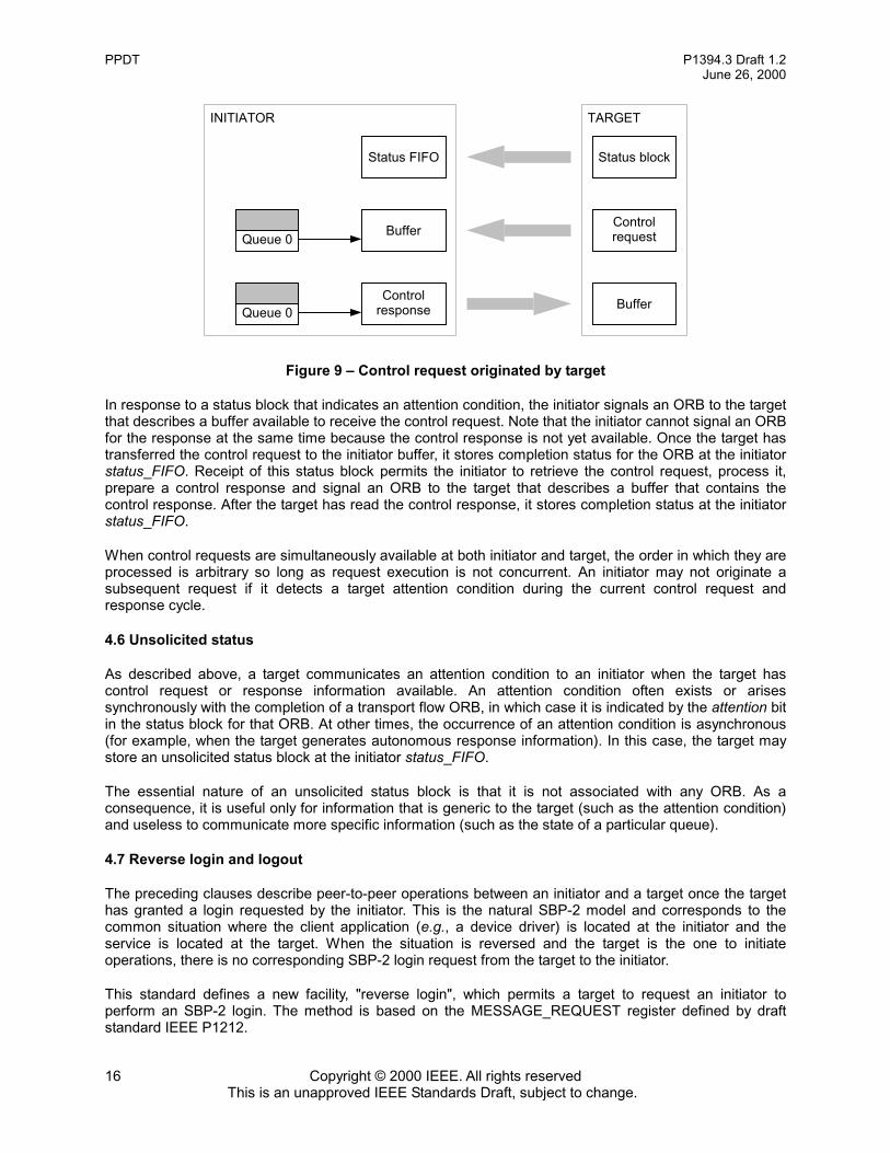
Figure 9 – Control request originated by target
In response to a status block that indicates an attention condition, the initiator signals an ORB to the targetthat describes a buffer available to receive the control request. Note that the initiator cannot signal an ORBfor the response at the same time because the control response is not yet available. Once the target hastransferred the control request to the initiator buffer, it stores completion status for the ORB at the initiatorstatus_FIFO. Receipt of this status block permits the initiator to retrieve the control request, process it,prepare a control response and signal an ORB to the target that describes a buffer that contains thecontrol response. After the target has read the control response, it stores completion status at the initiatorstatus_FIFO.
When control requests are simultaneously available at both initiator and target, the order in which they areprocessed is arbitrary so long as request execution is not concurrent. An initiator may not originate asubsequent request if it detects a target attention condition during the current control request andresponse cycle.
4.6 Unsolicited status
As described above, a target communicates an attention condition to an initiator when the target hascontrol request or response information available. An attention condition often exists or arisessynchronously with the completion of a transport flow ORB, in which case it is indicated by the attention bitin the status block for that ORB. At other times, the occurrence of an attention condition is asynchronous(for example, when the target generates autonomous response information). In this case, the target maystore an unsolicited status block at the initiator status_FIFO.
The essential nature of an unsolicited status block is that it is not associated with any ORB. As aconsequence, it is useful only for information that is generic to the target (such as the attention condition)and useless to communicate more specific information (such as the state of a particular queue).
4.7 Reverse login and logout
The preceding clauses describe peer-to-peer operations between an initiator and a target once the targethas granted a login requested by the initiator. This is the natural SBP-2 model and corresponds to thecommon situation where the client application (e.g., a device driver) is located at the initiator and theservice is located at the target. When the situation is reversed and the target is the one to initiateoperations, there is no corresponding SBP-2 login request from the target to the initiator.
This standard defines a new facility, "reverse login", which permits a target to request an initiator toperform an SBP-2 login. The method is based on the MESSAGE_REQUEST register defined by draftstandard IEEE P1212.
TARGETINITIATOR
Queue 0
Queue 0Control
response
Buffer Controlrequest
Buffer
Status FIFO Status block

P1394.3 Draft 1.2 PPDTJune 26, 2000
Copyright © 2000 IEEE. All rights reservedThis is an unapproved IEEE Standards Draft, subject to change.
17
Just as there is a need for reverse login, there are also times when the target has no more use for a loginand wishes the initiator to logout. Since a login already exists between initiator and target, there is no needto use the MESSAGE_REQUEST register. Instead, this standard defines a “reverse logout” facility thatuses the management service to signal the initiator to perform an SBP-2 logout.


P1394.3 Draft 1.2 PPDTJune 26, 2000
Copyright © 2000 IEEE. All rights reservedThis is an unapproved IEEE Standards Draft, subject to change.
19
5 Data structures
This document defines the format of those parts of the SBP-2 ORB and status block reserved by ANSINCITS 325-1998 for specification by command set standards. It also defines a format for controlinformation transferred between initiator and target and a message structure used for reverse login from atarget to an initiator. All data structures defined in the following clauses shall be aligned on quadletboundaries.
5.1 Transport flow ORBs
ANSI NCITS 325-1998 defines command block ORBs for SBP-2 devices; these have a common 20-byteheader and leave the definition of the subsequent quadlets to individual command set standards. Devicescompliant with this standard shall use 32-byte command block ORBs (renamed transport flow ORBs toemphasize their function) whose format is illustrated by Figure 10. Transport flow ORBs are used toregulate the transfer of application data or control information between initiator and target.
Figure 10 – Transport flow ORB
The usage of the next_ORB, data_descriptor, rq_fmt, spd, max_payload, page_size and data_size fieldsand the notify and page_table_present bits (abbreviated as n and p, respectively, in the figure above) isdefined by ANSI NCITS 325-1998. The rq_fmt field shall be zero.
NOTE – For most PPDT implementations the notify bit should always be one so that the SBP-2 initiatorsoftware may accurately determine completion status for each ORB; this is a consequence of the unorderedexecution model. Other implementations that do not require completion status notification for each ORB maybe possible but the details are beyond the scope of this document.
The direction bit (abbreviated as d in the figure above) shall specify the direction of data transfer for thebuffer. If the direction bit is zero, the target shall use Serial Bus read transactions to fetch data from thebuffer (the flow direction is from the initiator to the target). Otherwise, when the direction bit is one, thetarget shall use Serial Bus write transactions to store data in the buffer (the flow direction is from the targetto the initiator).
NOTE – The direction of data transfer is determined solely by the direction bit without reference to the queuenumber. Unspecified behavior may occur if an ORB’s direction bit does not match the expected data transferdirection for the queue.
spd
reservedf ms queue
data_size
signature
n rq_fmt(0) r d max_payload page_sizep
next_ORB
data_descriptor
most significant
least significant
reserved

PPDT P1394.3 Draft 1.2June 26, 2000
Copyright © 2000 IEEE. All rights reservedThis is an unapproved IEEE Standards Draft, subject to change.
20
The final bit (abbreviated as f in the figure above) shall be set to one to indicate that the initiator shall notsignal any subsequent ORBs with the same queue value as this ORB until the target allocates the queuenumber in a future CONNECT request or response. Otherwise the value of final bit shall be zero and theinitiator may continue to signal ORBs for the queue. When the final bit is one the notify bit shall also beone.
The special bit (abbreviated as s in the figure above) provides additional information pertinent toapplication data transferred from the initiator to the target. The meaning of the special bit is unspecifiedwhen either of the data_size or queue fields are zero or the direction bit is one. Otherwise the meaningand usage of the special bit are application-dependent and shall apply to all of the application datacontained within the buffer described by the ORB.
NOTE – Stream socket abstractions include the notion of out of band data, as some transport protocols allowportions of incoming data to be marked as "special" in some way. These special data blocks may be deliveredto the user out of the normal sequence—for example, expedited data in X.25 and other OSI protocols or theuse of urgent data in TCP by BSD Unix. The special bit enables such usage to be mapped to PPDT.
The end_of_message bit (abbreviated as m in the figure above) shall indicate whether or not a boundaryexists in the application data or control information transferred from the initiator to the target. The meaningof the end_of_message bit is unspecified when the direction bit is one. Otherwise, when end_of_messageis one, a boundary exists after the last byte of application data or control information described by theORB. In the case of application data, the nature of the boundary and its interpretation shall be specified bythe service definition. When the queue field is zero, the end_of_message bit shall also be one; all controlinformation for a single request or response shall be contained within one buffer.
NOTE – When end_of_message is one and data_size is zero, a boundary exists at the end of application dataor control information previously transferred to the target. The target flushes this data to the receivingapplication client and indicates the end_of_message condition.
The queue field shall specify either a queue number assigned by the target in either a CONNECT requestor response (see 6.3.1) or queue zero. When the queue field is zero, the final bit shall be zero and thenotify bit shall be one.
The signature field shall contain an identifying number assigned by the initiator and shall be unique withinthe context of a queue. Individual data buffers are uniquely identified by the combination of queue andsignature. For a particular queue, an initiator shall not reuse a signature value until either the queue hasbeen shutdown (see 6.3.2) or a status block has been received for a subsequent ORB in the same queue.This field is used to facilitate the resumption of data transfer after a bus reset or other transientinterruption while minimizing retransmission of data securely stored prior to the interruption (see 7.5).
5.2 Status block
As described by ANSI NCITS 325-1998, a target may store status at an initiator status_FIFO addresswhen a transport flow ORB completes (successfully or in error) or because of an unsolicited event (devicestatus change). Whenever the target has status to report and is enabled to do so, it shall store the statusblock illustrated by Figure 11.
Without regard to the value of the notify bit in the ORB to which status pertains, the target shall storecompletion status if any of the dead, attention, target_data_pending, special and end_of_message bits oreither of the status and residual fields are nonzero.

P1394.3 Draft 1.2 PPDTJune 26, 2000
Copyright © 2000 IEEE. All rights reservedThis is an unapproved IEEE Standards Draft, subject to change.
21
Figure 11 – Status block format
The first two quadlets of the status block are specified by ANSI NCITS 325-1998 and are thereforecommon to all PPDT devices. The definition and usage of the src, resp, len, sbp_status, ORB_offset_hiand ORB_offset_lo fields, as well as the dead bit (abbreviated as d in the figure above), are specified byANSI NCITS 325-1998.
The len field shall have a value of three to indicate that the length of the status block is four quadlets.
When resp and sbp_status are zero, the status field shall specify the completion status of the transportflow requested by the ORB, as encoded by the table below.
The attention bit (abbreviated as a in the figure above) indicates the availability of target controlinformation. When the attention bit is one, the initiator should signal an ORB for queue zero to retrieve thecontrol information. Once set to one by the target, this bit shall remain set in subsequent status blocksuntil the target successfully stores the control information in an initiator buffer.
The target_data_pending bit (abbreviated as t in the figure above) indicates the availability of targetapplication data for the queue specified by the ORB identified by ORB_offset_hi and ORB_offset_lo.When the target_data_pending bit is one, the initiator should signal an ORB for the specified queue toretrieve the application data. The target shall zero this bit when there is no pending application dataawaiting transfer to the initiator. The meaning of target_data_pending is unspecified for an unsolicitedstatus block.
The special bit (abbreviated as s in the figure above) provides additional information pertinent toapplication data transferred from the target to the initiator. The meaning of the special bit is unspecified foran unsolicited status block, if no data has been transferred, or when (in the ORB identified byORB_offset_hi and ORB_offset_lo) any of the data_size or queue fields or the direction bit are zero. Themeaning and usage of the special bit are application-dependent and shall apply to all of the applicationdata contained within the buffer described by the ORB.
The end_of_message bit (abbreviated as m in the figure above) shall indicate whether or not a boundaryexists in the application data or control information transferred from the target to the initiator. The meaningof the end_of_message bit is unspecified for an unsolicited status block or when the direction bit (in the
status Description
0 The application data or control information has been successfullytransferred; consult the residual field for details of the actual transfer length.
1 Invalid queue; the queue identified in the ORB is not allocated to an activeconnection.
2 Target reset by another initiator; all tasks aborted.
3 Abortive queue shutdown requested by target; no application data has beentransferred.
reserved
residual
ORB_offset_lo
src ORB_offset_hi
status
most significant
least significant
sbp_statusresp
r
lend
st ma

PPDT P1394.3 Draft 1.2June 26, 2000
Copyright © 2000 IEEE. All rights reservedThis is an unapproved IEEE Standards Draft, subject to change.
22
ORB identified by ORB_offset_hi and ORB_offset_lo) is zero. Otherwise, when end_of_message is one, aboundary exists after the last byte of application data or control information described by the ORB. In thecase of application data, the nature of the boundary and its interpretation shall be specified by the servicedefinition. When the queue field (in the ORB identified by ORB_offset_hi and ORB_offset_lo) is zero, theend_of_message bit in the associated status block shall also be one; all control information for a singlerequest or response shall be contained within one buffer.
When status is zero, the residual field shall specify the difference between the requested and actual datatransfer lengths, in bytes. The meaning of residual field is unspecified for an unsolicited status block.
When residual is negative, no data has been transferred because of a mismatch between the size of thebuffer and the data transfer length acceptable to the target: either the target's buffer space is too small toaccept the data described by the ORB to which the completion status pertains or else the buffer describedby the pertinent ORB is too small to accept the data available from the target. In these cases, the meaningof residual depends upon the value of the direction bit of the ORB to which the completion status pertains.When direction is zero (the flow direction is from the initiator to the target), the target shall calculateresidual by subtracting the size of the buffer provided by the initiator from the maximum acceptable datatransfer length. Otherwise, when direction is one (the flow direction is from the target to the initiator), thetarget shall calculate residual by subtracting the minimum acceptable data transfer length from the size ofthe buffer provided by the initiator. Negative values shall be encoded in two’s complement notation.
Otherwise, when residual is greater than or equal to zero, there is no mismatch between the size of thebuffer and the data transfer length to prevent data transfer. The target shall calculate residual bysubtracting the actual data transfer length from the size of the buffer provided by the initiator. A residualvalue greater than zero is not necessarily indicative of an error.
NOTE – Specifications for the use of the residual field are provided in 7.1 and 7.2.
5.3 Control information
Control information, both requests and their corresponding responses, may be exchanged betweeninitiator and target via transport flow ORBs whose queue field is zero (control ORBs). This indicates thatthe data in the buffer (or the data to be stored in the buffer) associated with the ORB is control informationrather than application data. Only one control request or response shall be transferred by an ORB; whenthe direction bit is zero the end_of_message bit in the ORB shall be one, otherwise the end_of_messagebit in the status block shall be one. If the initiator has provided more control information than the target canaccept or if the buffer is too small to receive all the target’s control information, no transfer shall take placeand the residual field shall indicate the appropriate transfer size (see 0 and 0). The format of the controlinformation in the buffer is illustrated by Figure 12.
Figure 12 – Control information format
The rq bit shall specify whether the control information contains a request or a response. A value of oneindicates a request.
responserq ctrl_function reserved
parameter(s)
most significant
least significant

P1394.3 Draft 1.2 PPDTJune 26, 2000
Copyright © 2000 IEEE. All rights reservedThis is an unapproved IEEE Standards Draft, subject to change.
23
The ctrl_function field shall specify the control function, as defined by the table below.
The response field is valid only when the rq bit is zero. In this case, it encodes a response indication forthe corresponding control function, as defined by the table below.
The remainder of the control information shall consist of zero or more parameters identified by aparameter ID (see Table 1). Relative to the start of the buffer, each parameter shall be quadlet-aligned andoccupy an integral number of quadlets. The first parameter shall start in the second quadlet of controlinformation and subsequent parameters, if any, shall immediately follow the preceding parameter. Theorder in which parameters appear is unimportant. Either the parameters shall completely fill the controlinformation or they shall be followed by a zero quadlet.
ctrl_function Name Comment
0 Reserved for future standardization
1 CONNECT Establish a connection with a particular service
2 SHUTDOWNQUEUE
Initiate the release of resources for a queue that willno longer be used
3 RELEASEQUEUE
After a queue is shutdown, confirm that resources maybe safely released
4 STATUS Query the availability of target data for queues otherthan the control queue
5 REVERSELOGOUT
The target no longer requires a login from the initiator;the initiator should logout as soon as possible.
6 – 7F16 Reserved for future standardization
response Definition
0 Request completed OK; response parameters aremeaningful.
1 Unknown control function.
2 Insufficient resources are available to complete therequest; the same request may succeed if resubmittedlater.
3 The service identified by the SERVICE_ID parameterdoes not exist.
4 Mismatch between the queue parameter(s) provided ina CONNECT request and those expected by theservice.
5 The connection request is refused.
FF16 Unspecified error.

PPDT P1394.3 Draft 1.2June 26, 2000
Copyright © 2000 IEEE. All rights reservedThis is an unapproved IEEE Standards Draft, subject to change.
24
Table 1 – Parameter ID values
The parameter ID shall specify the parameter format, either immediate or variable-length. The mostsignificant bit of the parameter ID determines the format; parameters whose ID values are in the rangezero to 7F16, inclusive, shall conform to the format specified by Figure 13 while those in the range 8016 –FF16, inclusive, shall conform to the format specified by Figure 14. All parameter ID values not specifiedare reserved for future standardization.
The format of immediate parameters is shown below.
Figure 13 – Immediate parameter format
The parameter_ID field shall specify the parameter, as encoded by Table 1.
The parameter_value field shall specify the immediate value of the parameter. Unless otherwise specifiedfor a particular value of parameter_ID, the value field shall contain an unsigned 24-bit number.
The format of variable-length parameters (which are usually ASCII text strings) is shown below.
Parameter
ID NameValue
restrictions Description
0 0 Indicates end of parameter list in control information(optional).
1 TASK_SLOTS Minimum 1per queue
For a particular connection, the maximum number of ORBspermitted in the task set. The initiator shall observe the limitestablished by the target and may optionally provide thisparameter to indicate a self-imposed limit. Task slots areallocated per connection and may be used for any of theconnection's queues.
2 I2T_QUEUE The queue number assigned to the connection for thetransport of application data from the initiator to the target
3 T2I_QUEUENonzero;
FF16 maximum The queue number assigned to the connection for thetransport of application data from the target to the initiator
4 MODE 0, 1 Specifies the desired mode at the time a connection to aservice is established. Zero indicates datagram mode; onespecifies stream mode.
8016 SERVICE_ID 40 bytesmaximum
An ASCII text string (without leading or trailing blankcharacters) that uniquely identifies a service.
8116 QUEUE_INFO A bit map that reports the state of target_data_pending forqueues other than the control queue (see Figure 15).
parameter_ID parameter_valuemost significant least significant

P1394.3 Draft 1.2 PPDTJune 26, 2000
Copyright © 2000 IEEE. All rights reservedThis is an unapproved IEEE Standards Draft, subject to change.
25
Figure 14 – Variable-length parameter format
The parameter_ID field shall specify the parameter, as encoded by Table 1.
The length field shall specify the length of the parameter_value field, in bytes. Pad bytes, if present, areexcluded from the value of length.
The parameter_value field shall contain the value of the parameter and shall commence with the mostsignificant byte of the parameter value. If the length of the parameter is not a multiple of four, theparameter value shall be padded with trailing bytes of zero.
5.4 Queue information
Queue information is a variable-length parameter that conforms to the format illustrated by Figure 15.Each entry in the array reports status information for a queue implemented by the target. Queueinformation shall include all active queues but may be truncated to omit inactive queues implemented bythe target.
Figure 15 – Queue information format
The value of parameter_ID shall be 8116.
The value of length shall be nonzero and less than or equal to 256.
Each queue_info entry provides information for an individual queue; this array of bytes is directly indexedby the queue number. The first entry in the array is reserved.3 For all other queues, the format of thequeue_info byte is specified by Figure 16.
3 Queue zero is always active; the availability of control information is indicated by the status block attention bit.
parameter_ID (8116) length
parameter_ID length
parameter_value
most significant
least significant
pad with zero bytes as necessary
most significant
least significant
reserved queue_info[1] queue_info[2] queue_info[3]
queue_info[FC16] queue_info[FD16] queue_info[FE16] queue_info[FF16]

PPDT P1394.3 Draft 1.2June 26, 2000
Copyright © 2000 IEEE. All rights reservedThis is an unapproved IEEE Standards Draft, subject to change.
26
Figure 16 – Queue information byte format
The active bit shall be zero if the queue is not implemented by the target or not assigned to an establishedconnection. A value of one indicates that the queue is in use by a connection. The status of a queue,active or inactive, is as perceived from the perspective of the target.
The target_data_pending bit (abbreviated as t in the figure above) indicates the availability of targetapplication data for the queue. When the target_data_pending bit is one, the initiator should signal atransport flow ORB for the specified queue to retrieve the application data (unless such an ORB is alreadyactive). The target shall zero this bit when there is no pending application data awaiting transfer to theinitiator.
5.5 Reverse login request and response
The reverse login facility utilizes a 64-byte block write addressed to an initiator's MESSAGE_REQUESTregister or a target's MESSAGE_RESPONSE register. The format of the data payload conforms to draftstandard IEEE P1212 and is illustrated by Figure 17.
Figure 17 – Reverse login request / response format
In a reverse login request addressed to an initiator's MESSAGE_REQUEST register, the notify bit(abbreviated as n above) shall be one; the initiator is requested to write a response to the target'sMESSAGE_RESPONSE register. In the response returned to the target, notify shall be one if the initiatordoes not implement the reverse login facility; otherwise it shall be zero and response shall indicate thecompletion status of the request.
The msg_label field shall be zero.
The specifier_ID field shall be 00 502916.
The version field shall be zero.
directory_IDreserved
eui_64
responsetarget_request reserved
active treservedmost significant least significant
reserved
n
version
specifier_ID_himsg_labelreserved
specifier_ID_lo
most significant
least significant

P1394.3 Draft 1.2 PPDTJune 26, 2000
Copyright © 2000 IEEE. All rights reservedThis is an unapproved IEEE Standards Draft, subject to change.
27
The eui_64 field shall be equal to the EUI-64 in the target's bus information block. The initiator shall leavethis field unchanged when a response is written to the MESSAGE_RESPONSE register.
The target_request field shall contain a value specified by the table below; all values not explicitly definedare reserved for future standardization.
target_request Name Comment
0 NOP No effects at initiator; response indicates whether ornot initiator supports reverse login.
1 REVERSE LOGIN Requests the initiator to login in to the specified nodeand unit directory.
The response field shall be zero in a reverse login request. In the response returned to the target'sMESSAGE_RESPONSE register, response shall indicate completion status as specified by the followingtable.
response Name Comment
0 OK The request is acknowledged and the initiator willattempt the requested action.
1 RESOURCESUNAVAILABLE
The initiator cannot attempt a login at present; asubsequent REVERSE LOGIN request by the targetmay succeed.
FF16 REJECTED The request is rejected for unspecified reasons.
The directory_ID field shall identify the unit to which the initiator is requested to transmit a LOGIN request.A directory's ID may be specified explicitly by a Directory_ID entry or, absent such an entry, implicitly by theleast significant 24 bits of the base address of the directory within node space.


P1394.3 Draft 1.2 PPDTJune 26, 2000
Copyright © 2000 IEEE. All rights reservedThis is an unapproved IEEE Standards Draft, subject to change.
29
6 Control operations
Before application client(s) and service(s) may exchange data in uni- or bi-directional transport flows(explained in detail in section 7), control operations are necessary to set up the communication paths. Thissection specifies the methods used by both initiator and target to establish and manage connections forthese transport flows.
6.1 Login, reverse login and queue zero
Access to a target compliant with this standard commences with an SBP-2 login request by the initiator.Upon successful completion of the login request, the target has reserved resources for use by the initiator:
– SBP-2 registers assigned by the target at the time of the login (the AGENT_STATE,AGENT_RESET, ORB_POINTER, DOORBELL and UNSOLICITED_STATUS_ENABLE registers);
– queue zero, the control queue; and
– two task slots for use by queue zero ORBs.
In cases where a target wishes to communicate with an initiator but no login exists, a target may use the"reverse login" facility to request an SBP-2 login from the initiator. The target constructs a reverse loginmessage (see 5.5) and stores it at the initiator's MESSAGE_REQUEST register. If the target receives asuccess response at its own MESSAGE_RESPONSE register, the initiator either has attempted or shallattempt to establish a login. An initiator that initiates SBP-2 login in response to a reverse login requestshould persist in its attempts until a login response is received from the target.
NOTE – A target should not create a flood of reverse login requests; if no response is received to a reverselogin request, the target should wait a reasonable, implementation-dependent time before retransmission of athe request.
Once queue zero exists, either initiator or target may use it in a peer-to-peer fashion to communicatecontrol information, requests or responses, to the other. At no time shall the task set contain more thantwo control ORBs.
The completion of a request requires two ORBs, one that describes the control information buffer thatcontains the request and a complementary ORB that describes the control information buffer for theresponse. Although queue zero provides full peer-to-peer functionality between initiator and target, thedetails of its use are asymmetric and vary according to whether the initiator or the target is the requester.
When an initiator issues a request to a target, they shall perform the following operations:
a) The initiator shall store the request and its associated parameters (if any) in a buffer in systemmemory and signal to the target fetch agent an ORB, whose queue field and direction bit are zeroand end_of_message bit is one, that describes the control information buffer;
b) The target shall fetch the ORB and read the control information buffer. The status block stored bythe target to complete the ORB may have its attention bit set to one to indicate that the target intendsto transfer control information (the response) to the initiator;
c) At any time the initiator receives a status block whose attention bit is one and there is no ORB in thetask set whose queue field is zero and direction bit is one, the initiator shall create such an ORB andplace it in the task set; and
d) Once the target has executed the indicated request and there is an ORB in the working set whosequeue field is zero and direction bit is one, the target shall store the response data in the bufferdescribed by the ORB and then store completion status for the ORB. So long as the target has

PPDT P1394.3 Draft 1.2June 26, 2000
Copyright © 2000 IEEE. All rights reservedThis is an unapproved IEEE Standards Draft, subject to change.
30
pending control information to transfer to the initiator, it shall continue to set the attention bit to one inany status block (including unsolicited status) stored into the initiator status_FIFO.
NOTE – In order to reduce ORB fetch latency, the initiator may place two control information ORBs in the taskset at the same time, the first for the request (with a direction bit of zero) and the second for the response (witha direction bit of one). Although the algorithm described above works correctly even if the initiator awaits astatus block whose attention bit is one before signaling a target response ORB to receive the response data, itis more efficient to signal both ORBs at the same time.
When a target issues a request to an initiator, they shall perform the following operations:
a) The target shall set the attention bit to one in a status block stored into the initiator status_FIFO.Either unsolicited status or completion status associated with an ORB may be used. So long as thetarget has pending control information to transfer to the initiator, it shall continue to set the attentionbit to one in any status block stored into the initiator status_FIFO.
b) At any time the initiator receives a status block whose attention bit is one and there is no ORB in thetask set whose queue field is zero and direction bit is one, the initiator shall create such an ORB andplace it in the task set;
c) Once there is an ORB in the working set whose queue field is zero and direction bit is one, the targetshall store the control information data (request) in the buffer described by the ORB and then storecompletion status for the ORB. The attention bit shall be zero in the status block associated with theORB;
d) When the initiator has executed the indicated request, it shall store the response and its associatedparameters (if any) in a buffer in system memory and signal to the target fetch agent an ORB thatdescribes the control information buffer. The ORB’s queue field and direction bit shall be zero andthe end_of_message bit shall be one;
e) The target shall fetch the ORB and read the response from the control information buffer. The statusblock stored by the target to complete the ORB may have its attention bit set to one if the targetintends to transfer other control information (request or autonomous response) to the initiator.
It is possible for both initiator and target to initiate requests at roughly the same time. In this case theworking set contains an ORB for transfer of the request from initiator to target while the status blockattention condition is simultaneously asserted by the target. The ordered execution properties of queuezero give a natural precedence to initiator requests over target requests, as follows. When a target fetchesan ORB whose queue field and direction bit are zero and whose end_of_message bit is one, the requestcontained in the control information shall be processed before a request is transferred to the initiator.Consequently, if a target has an uncompleted initiator request when it fetches a control ORB and whosedirection bit is one it shall not store any control information except the response that completes therequest.
When neither initiator nor target have outstanding requests or responses there shall be no ORBs in thetask set whose queue field is zero.
6.2 Autonomous response information
The preceding clause describes the use of queue zero for request / response pairs between initiator andtarget. It is also possible for either initiator or target to autonomously transfer response information to theother. Autonomous response information is typically status information and does not necessarily requireany additional action on the part of the recipient.
Autonomous response information may be sent for queue status information, identified by a ctrl_functionvalue of STATUS.
The response code in autonomous response information shall be zero.

P1394.3 Draft 1.2 PPDTJune 26, 2000
Copyright © 2000 IEEE. All rights reservedThis is an unapproved IEEE Standards Draft, subject to change.
31
Autonomous response information shall not be transferred while there is an uncompleted control request.A target requests the transfer of autonomous response information by means of the status block attentionbit. If a target asserts attention and subsequently fetches an initiator request ORB, it shall first completethe initiator’s control request and transfer the corresponding response information to the initiator beforetransferring the autonomous response information. The attention bit shall remain asserted in any statusblocked stored in the initiator status_FIFO while the transfer of the autonomous response information ispending.
6.3 Connection management
Control ORBs are used to establish and terminate connections that permit the flow of application databetween clients and services in either initiators or targets. The control requests are CONNECT,SHUTDOWN QUEUE and RELEASE QUEUE. The connection type is established when the connection iscreated and is implicitly encoded by the I2T_QUEUE and T2I_QUEUE parameters present in theconnection request or response information, as specified by Table 2.
Table 2 – Connection type encoded by queue ID parameters
Connection type I2T_QUEUE value T2I_QUEUE value
unrestricted —Unidirectional
— unrestricted
Bi-directional(nonblocking) not equal to T2I_QUEUE not equal to I2T_QUEUE
Bi-directional(blocking) equal to T2I_QUEUE equal to I2T_QUEUE
Unidirectional connections are described by a single parameter, I2T_QUEUE or T2I_QUEUE. If bothparameters are present, the connection is bi-directional and is either blocking or nonblocking according towhether the two parameter values are equal or different, respectively.
6.3.1 Connection establishment
Before a PPDT client application may communicate with a service, the transport layer shall allocate andconfirm necessary resources by means of a control request with a ctrl_function code of CONNECT and itscorresponding response. The operations are fundamentally similar whether the service resides at theinitiator or the target, but because the initiator and target control different resources, the procedures aredescribed separately.
The minimal initiator resource required for a connection is sufficient system memory to hold the ORBs thatform the subset of the task set allocated to the connection.
The minimum target resources required for a connection are one or two available queue numbers as wellas local memory to hold active ORBs and their associated context (up to the maximum set by the targetvia the TASK_SLOTS parameter).
With respect to task slots, the initiator shall guarantee that the task set never contains more active ORBsfor the connection than the smaller of the TASK_SLOTS value specified by the target or optionallyspecified by the initiator. It is unimportant whether the CONNECT request was originated by the initiator ortarget.
Once a successful control response has been received (by either the initiator or target, as appropriate) fora connection request, the initiator may place ORBs into the task set that use the queue number(s)

PPDT P1394.3 Draft 1.2June 26, 2000
Copyright © 2000 IEEE. All rights reservedThis is an unapproved IEEE Standards Draft, subject to change.
32
specified by the target. A queue number remains valid until either a LOGOUT (either explicit on the part ofthe initiator or implicit as the result of a failure to reconnect after a bus reset) or the queue is shutdown.
6.3.1.1 Connection established by an initiator
When a PPDT application client at an initiator desires to establish a connection with a target service, theinitiator shall create a control ORB whose buffer contains a CONNECT control request. The initiator shallspecify the SERVICE_ID and MODE parameters. The initiator may specify the TASK_SLOTS parameter.
If the connection is established, the target shall return response data that specifies TASK_SLOTS and oneor both of the I2T_QUEUE and the T2I_QUEUE parameters. When the initiator has provided the optionalTASK_SLOTS parameter in its request, the target should return a TASK_SLOTS value less than or equalto that specified by the initiator.
6.3.1.2 Connection established by a target
A PPDT application client at a target that desires to establish a connection with an initiator service shallrequest the target to create control information that contains a CONNECT control request and signal theinitiator to retrieve the control information by asserting the attention bit in a status block. The CONNECTcontrol request shall specify the SERVICE_ID, MODE, TASK_SLOTS and one or both of the I2T_QUEUEand T2I_QUEUE parameters.
If the requested service exists at the initiator and supports the requested transport flow mode, datagram orstream, the connection may be confirmed by a control response from the initiator. No parameters arerequired in the control response, but the initiator may specify the TASK_SLOTS parameter.
The initiator shall not use the queue number(s) identified by the I2T_QUEUE or T2I_QUEUE parametersuntil successful completion status has been stored at the initiator’s status_FIFO for the ORB thattransferred the control response to the target.
6.3.2 Queue shutdown
Although more than one queue may be allocated as the result of a connection request, queues areshutdown individually; there is no unified disconnection request that affects all of a connection’s queues.When all queues allocated to a connection are shutdown, the connection no longer exists and allresources allocated to it may be released.
Either the client application or the service may request queue shutdown; there are no fundamentaldifferences. A more important consideration is whether it is the queue’s data producer or data consumerthat initiates the shutdown. Queue shutdown requested by the producer may be orderly while shutdownrequested by the consumer is unlikely to be orderly, as summarized by the table below.
Queue shutdown requestor
Data transport flow Initiator Target
Initiator to target(I2T_QUEUE) Orderly Abortive
Target to initiator(T2I_QUEUE) Abortive Orderly
Bi-directional(I2T_QUEUE equals
T2I_QUEUE)Application-dependent

P1394.3 Draft 1.2 PPDTJune 26, 2000
Copyright © 2000 IEEE. All rights reservedThis is an unapproved IEEE Standards Draft, subject to change.
33
An orderly shutdown occurs when the consumer is able to successfully receive all the data produced priorto queue shutdown. An abortive shutdown is characterized by the loss of data between the two endpoints.Whether or not the shutdown of a queue used to transfer data in either direction (i.e., a queue used by abi-directional, blocking connection) is abortive or orderly is dependent upon usage rules agreed by theclient application and service and is beyond the scope of this document.
6.3.2.1 Queue shutdown by an initiator
When an application client or service at an initiator desires to shutdown a queue, the initiator shall signal atransport flow ORB to the target whose final and notify bits are one and whose queue field specifies thequeue to be shutdown. The initiator shall not signal any subsequent ORBs with the same queue valueunless the target allocates the queue number upon future establishment of a connection. A data buffermay be associated with a transport flow ORB whose final bit is one.
If the direction of data transfer via the queue is from target to initiator, the initiator shall signal a controlORB whose buffer contains a SHUTDOWN QUEUE control request whose T2I_QUEUE parameter isequal to the value of the queue field in the final ORB. This avoids a deadlock with the target and insuresthat the final ORB is eventually fetched and processed by the target.
NOTE – If the direction of data transfer via the queue is from initiator to target, the initiator may signal a controlORB whose buffer contains a SHUTDOWN QUEUE control request whose I2T_QUEUE parameter is equal tothe value of the queue field in the final ORB. This may be appropriate if the initiator wishes to abortivelyshutdown a queue or necessary if the target is unresponsive and not processing ORBs for the queue.
A target that receives a SHUTDOWN QUEUE request shall commence execution of all active ORBs forthe queue identified by the I2T_QUEUE or T2I_QUEUE parameter. If the direction of data transfer is fromthe initiator to the target, the target shall not defer completion of any ORB for the queue solely becausethe receiving client application or service has not provided sufficient buffer space but shall complete theORB without transferring all available data. Otherwise, if the direction of data transfer is from the target tothe initiator, the target shall not defer completion of any ORB for the queue solely because the clientapplication or service has not provided sufficient data. Regardless of the direction of data transfer, theresidual field in the status block for the ORB shall report the actual data transfer.
Once the target completes any indicated data transfer for the final ORB, it shall mark the queue asprovisionally shutdown and store completion status at the initiator’s status_FIFO. The target may not yetrelease the resources associated with the queue. If the initiator signals any subsequent ORBs whosequeue field identifies the provisionally shutdown queue, the target shall reject these with a status of one(invalid queue).
After the target has completed the final ORB, it shall discard any data generated by a client application orservice for the provisionally shutdown queue. Because a service or client application at the initiator isunaware of the discarded data, if any, the shutdown of a queue used for data transfer from the target tothe initiator may be disorderly (abortive) when requested by the initiator.
When the initiator receives completion status for the final ORB, it shall signal a control ORB whose buffercontains a RELEASE QUEUE control request. For a queue used to transfer data in only one direction, theinitiator shall specify the I2T_QUEUE or T2I_QUEUE parameter, as appropriate, to identify the queue tobe released. For a queue used to transfer data in either direction (i.e., a queue used by a bi-directional,blocking connection), the initiator shall specify both parameters and their values shall be equal. Ifcompletion status for the control ORB indicates that the RELEASE QUEUE control request was notdelivered to the target, the initiator shall either signal the control ORB again or reset the target by a write toits RESET_START register. Once completion status indicates successful receipt of the RELEASE QUEUEcontrol request by the target, no additional initiator action is necessary. The RELEASE QUEUE controlrequest has no corresponding response.

PPDT P1394.3 Draft 1.2June 26, 2000
Copyright © 2000 IEEE. All rights reservedThis is an unapproved IEEE Standards Draft, subject to change.
34
A target that receives a RELEASE QUEUE control request whose I2T_QUEUE or T2I_QUEUE parameteridentifies a queue marked provisionally shutdown should release all resources allocated to the queue.Otherwise the target shall ignore the request. Once no active queues remain for the connection to whichthe queue was originally allocated, any additional connection resources should be released. The targetshall not respond to a RELEASE QUEUE control request.
6.3.2.2 Queue shutdown by a target
When an application client or service at a target desires to shutdown a queue, it shall request the creationof a buffer that contains a SHUTDOWN QUEUE control request and signal the initiator to retrieve thecontrol request by asserting the attention bit in a status block. For a queue used to transfer data in onlyone direction, the target shall specify the I2T_QUEUE or T2I_QUEUE parameter, as appropriate, toidentify the queue to be shutdown. For a queue used to transfer data in either direction (i.e., a queue usedby a bi-directional, blocking connection), the target shall specify both parameters and their values shall beequal. Once completion status indicates successful receipt of the SHUTDOWN QUEUE request by theinitiator, the target shall not defer completion of any ORB for the queue. When the direction of datatransfer is from the initiator to the target, transport flow ORBs shall be completed without data transfer.Otherwise, when the direction of data transfer is from the target to the initiator, the completion of transportflow ORBs shall not be delayed solely because insufficient data is available. In both cases, the residualfield in the status blocks stored for the transport flow ORBs shall report the actual data transfer.
NOTE – If the direction of data transfer via the queue is from target to initiator and an orderly shutdown isintended, the target’s client application or service should cease generation of data and the target shouldcomplete all outstanding data transfers before issuing the SHUTDOWN QUEUE request.
An initiator that receives a SHUTDOWN QUEUE request shall signal a transport flow ORB to the targetwhose final and notify bits are one and whose queue field specifies the queue identified in the controlparameters for the request. The initiator shall not signal any subsequent ORBs with the same queue valueunless the target allocates the queue number upon future establishment of a connection. A data buffermay be associated with a transport flow ORB whose final bit is one.
Once the target completes any indicated data transfer for the final ORB, it shall mark the queue asprovisionally shutdown and store completion status at the initiator’s status_FIFO. The target may not yetrelease the resources associated with the queue. If the initiator signals any subsequent ORBs whosequeue field identifies the provisionally shutdown queue, the target shall reject this with a status of one(invalid queue).
After the target has completed the final ORB, it shall discard any data generated by a client application orservice for the provisionally shutdown queue. Because a service or client application at the initiator isunaware of the discarded data, if any, the shutdown of a queue used for data transfer from the initiator tothe target may be disorderly (abortive) when requested by the target.
When the initiator receives completion status for the final ORB, it shall signal a control ORB whose buffercontains a RELEASE QUEUE control request. For a queue used to transfer data in only one direction, theinitiator shall specify the I2T_QUEUE or T2I_QUEUE parameter, as appropriate, to identify the queue tobe released. For a queue used to transfer data in either direction (i.e., a queue used by a bi-directional,blocking connection), the initiator shall specify both parameters and their values shall be equal. Ifcompletion status for the control ORB indicates that the RELEASE QUEUE control request was notdelivered to the target, the initiator shall either signal the control ORB again or reset the target by a write toits RESET_START register. Once completion status indicates successful receipt of the RELEASE QUEUEcontrol request by the target, no additional initiator action is necessary. The RELEASE QUEUE controlrequest has no corresponding response.
A target that receives a RELEASE QUEUE control request whose I2T_QUEUE or T2I_QUEUE parameteridentifies a queue marked provisionally shutdown should release all resources allocated to the queue.Otherwise the target shall ignore the request. If no active queues remain for the connection to which the

P1394.3 Draft 1.2 PPDTJune 26, 2000
Copyright © 2000 IEEE. All rights reservedThis is an unapproved IEEE Standards Draft, subject to change.
35
queue was originally allocated, any additional connection resources should be released. The target shallnot respond to a RELEASE QUEUE control request.
6.3.2.3 Simultaneous queue shutdown by initiator and target
Unaware of the other’s actions, an initiator and a target might initiate shutdown of the same queuesimultaneously. In this case, there is no guarantee of orderly shutdown.
If an initiator receives a SHUTDOWN QUEUE control request that identifies a queue for which a final ORBhas already been signaled it shall take no action. Similarly, no action is required of a target when aninitiator signals a final ORB at roughly the same time as the target issued a SHUTDOWN QUEUE request.
6.4 Queue status information
A target may transfer autonomous queue status information to an initiator when target data is available fora queue (i.e., target_data_pending would be set to one in the status blocks stored for any transport flowORBs for the queue) but the initiator has not signaled any ORBs for the queue. In this circumstance, thetarget is not able to indicate the presence of data except by an indirect route.
The target may indicate the availability of control information by setting the attention bit to one in anystatus block stored at the initiator's status_FIFO. The initiator should signal a control ORB whose directionbit is one in order to retrieve the control information from the target. When such an ORB is signaled, thetarget may transfer autonomous response information for the STATUS control function that contains aQUEUE_INFO parameter. The queue information notifies the initiator which queues have target dataavailable.
If there are no ORBs in the target's task set, the target may communicate the attention bit to the initiator bymeans of an unsolicited status block. Once the initiator is aware of a target attention condition, it shouldsignal a control ORB whose direction bit is one.
6.5 Logout and reverse logout
When PPDT client applications and services are idle—and expected to remain idle for some time—it maybe desirable to relinquish the login. This frees the fetch agent, memory used to hold the working set ofORBs and other target resources allocated to the login for potential use by another initiator.
NOTE – Under normal conditions, a logout should not be performed until all queues other than queue zero areshutdown.
When an initiator wishes to release a login, it performs an SBP-2 logout. Contrariwise, a target that has nomore immediate use for a login is unable to perform the logout directly. Instead, it creates a buffer thatcontains a REVERSE LOGOUT control request and signals the initiator to retrieve the control request byasserting the attention bit in a status block.
An initiator that receives a REVERSE LOGOUT control request should perform an SBP-2 logout as soonas possible. The reverse logout request by the target is advisory; the initiator may have informationunavailable to the target that causes it to ignore the request. Whether or not the initiator honors thereverse logout request, it shall not return response information to the target.


P1394.3 Draft 1.2 PPDTJune 26, 2000
Copyright © 2000 IEEE. All rights reservedThis is an unapproved IEEE Standards Draft, subject to change.
37
7 Transport flow operations
Once a connection is established between a client application and a service, work is accomplished by theuni- or bi-directional flow of application-dependent data between the two. This section describes transportflow (and error recovery procedures) from the viewpoint of a queue instead of that of a connection; thereader may generalize from a single queue's operation to two coordinated queues that form a nonblockingbi-directional connection.
Service implementers select a datagram or stream mode of transport flow. The datagram mode is thesimplest: there is a one-to-one relationship between ORBs, buffers and service data units (SDUs), asillustrated by Figure 18. The end of an SDU is demarcated by the end_of_message bit, which is alwaysone when the datagram mode is used.
Figure 18 – Transport flow (datagram mode)
The stream mode permits SDU boundaries (e.g., the separation between pages or print jobs for a printer)to occur without regard for the boundaries between data buffers specified by different ORBs. Figure 19illustrates the relationship between stream data, the ORBs that describe its buffers and the SDUs.
Figure 19 – Transport flow (stream mode)
SDU
SDU
SDU
SDU
ORBs Buffers
SDU
SDU
SDU
ORBs Buffers

PPDT P1394.3 Draft 1.2June 26, 2000
Copyright © 2000 IEEE. All rights reservedThis is an unapproved IEEE Standards Draft, subject to change.
38
In the preceding figure, the stream data is assumed to be self-descriptive: it may be parsed by its recipientwithout the necessity for the ORBs to explicitly mark the SDU boundaries. When in stream mode, theend_of_message bit may be used to signal the end of SDUs, whether or not they span more than onebuffer, as illustrated by Figure 20.
Figure 20 – Transport flow (stream mode with explicit SDUs)
In the preceding figure, the end_of_message bit is zero in all but the last ORB.
7.1 Data transfer to a target
Application data is transferred to a target by means of transport flow ORBs whose direction bit is zero.Within the limits of TASK_SLOTS allocated by the target at the time the connection (identified by thequeue field) was established, the initiator may signal more than one such outstanding transport flow ORBto the task set at a time. ORB fetch latency is reduced if the initiator is permitted to have at least two suchoutstanding ORBs in the task set.
The target transport may use read requests that address the data buffer in arbitrary order so long as noneof the data is presented to an application client out of order. Upon successful completion of the datatransfer, the residual field in the status block shall be zero.
The transport flow mode, datagram or stream, established when the connection was created, governsbehavior when the initiator has more data available than the target is capable of processing at one time.For stream mode, this condition cannot arise; the target transfers data within the limits of local memory,delivers the data to the application client and continues to transfer data as local memory is released by theapplication client. Barring an unrecoverable error in the data transport or application client, all of the datadescribed by the ORB is eventually transferred.
When datagrams are used, the possibility exists that an SDU is larger than the maximum acceptable tothe target. In this case, no data shall be transferred and the residual field shall indicate the error condition.Figure 21 shows the relationship between the initiator’s data buffer, the maximum SDU acceptable to thetarget and the value of residual. For simplicity, the figure assumes that no page table is used.
Figure 21 – Excess initiator data (datagram mode)
SDU
ORBs Buffers
Maximum SDU
residual(negative)
data_size

P1394.3 Draft 1.2 PPDTJune 26, 2000
Copyright © 2000 IEEE. All rights reservedThis is an unapproved IEEE Standards Draft, subject to change.
39
The initiator may calculate the target’s maximum acceptable SDU size by adding residual to data_size.
7.2 Data transfer to an initiator
Application data is transferred to an initiator by means of transport flow ORBs whose direction bit is one.Within the limits of TASK_SLOTS allocated by the target at the time the connection (identified by thequeue field) was established, the initiator may signal more than one such outstanding transport flow ORBto the task set at a time. ORB fetch latency is reduced if the initiator is permitted to have at least two suchoutstanding ORBs in the task set.
A target shall report the availability of data for a queue by setting target_data_pending bit to one in allstatus blocks stored for that queue’s ORBs, regardless of the value of their direction bit, so long as thereis untransferred data. If the initiator has signaled no ORBs for a queue, the target may set attention to onein the status block for any ORB. This requests the initiator to signal a control ORB to transfer queueinformation from the target (see 6.4) which in turn causes the initiator to signal transport flow ORBs whosedirection bit is one for the queues with available data.
The target transport may use write requests that address the data buffer in arbitrary order so long assuccessful completion status is not reported to the initiator until the quantity of data identified by residualhas been transferred. There is no requirement to store data in the entire buffer provided by the initiatorbefore reporting successful completion status.
In stream mode, a transport flow ORB may be completed as soon as some data has been stored in theinitiator’s buffer; there is no requirement to defer completion of the ORB until the entire buffer provided bythe initiator has been filled with data by the target. Figure 22 illustrates the positive residual that is reportedin this case.
Figure 22 – Partial data transfer (stream mode)
The initiator may calculate the actual data transfer length by subtracting residual from data_size.4
The transport flow mode, datagram or stream, established when the connection was created, governsbehavior when the target has more data available than the initiator is capable of processing at one time.For stream mode, this condition cannot arise; the target transfers data (supplied by its application client)within the limits of the data buffer provided by the initiator; if more data is available from the applicationclient, the target_data_pending bit shall be one and the target awaits a subsequent ORB for the samequeue whose direction bit is one. Unless an unrecoverable error occurs in the data transport, the targetcontinues to fill initiator buffers so long as data is available.
When datagrams are used, the possibility exists that an SDU available at the target is larger than the databuffer provided by the initiator. In this case, no data shall be transferred and the residual field shall indicatethe error condition. Figure 23 shows the relationship between the initiator’s data buffer, the SDU availableat the target and the value of residual. Although the figure assumes that no page table is used, the
4 This example assumes that no page table is used. If a page table were present, data_size would not specify the
size of the buffer; the initiator would have to derive the buffer size from segment sizes specified by the page table.
Stream datatransferred
residual(positive)
data_size

PPDT P1394.3 Draft 1.2June 26, 2000
Copyright © 2000 IEEE. All rights reservedThis is an unapproved IEEE Standards Draft, subject to change.
40
relationships remain valid if a page table is present—except that the buffer size is summed from the pagetable elements instead of being directly available as data_size.
Figure 23 – Excess target data (datagram mode)
The initiator may calculate the minimum buffer size necessary to receive the SDU by subtracting residualfrom data_size.
7.3 Completion status
The target may signal completion status for a transport flow ORB by storing a status block to the initiatorstatus_FIFO active for the login. All pending request subactions for the data transfer specified by the ORBand for any previously signaled ORBs with the same queue value shall be completed before the targetstores a status block for the ORB to the initiator status_FIFO.
Not all values of the resp, sbp_status, status and residual fields are meaningful when consideredcollectively; the table below lists valid combinations within a status block. Field values other than thosewithin the table shall not be reported by the target.
resp sbp_status status residual Comment
Zero or greater Within the limits of the buffer provided, allavailable data has been transferred.
0Negative
Possible only in datagram mode: the SDU istoo large to be transferred. When thedirection bit in the ORB is zero, the maximumSDU is calculated as data_size + residualotherwise the maximum SDU is calculated asdata_size - residual.
0
123
REQUESTCOMPLETE
nonzero Unspecified
Unspecified
TRANSPORTFAILURE
0x164x168x16Cx16FF16
Unspecified Unspecified
When a transport failure occurs, it may beimpossible to determine the requested datatransfer length—and therefore impossible tocalculate residual.
ILLEGALREQUEST FF16 Unspecified
No data has been transferred; because theORB is malformed it is not possible tocalculate residual.
data_size
residual(negative)
SDU

P1394.3 Draft 1.2 PPDTJune 26, 2000
Copyright © 2000 IEEE. All rights reservedThis is an unapproved IEEE Standards Draft, subject to change.
41
resp sbp_status status residual Comment
VENDORDEPENDENT Unspecified Definition of almost all fields in the status
block is left to the device manufacturer.
7.4 Execution context for active ORBs
This document specifies a data transport between services and their application clients that is reliableacross interruptions, such as a bus reset, that cause target task set(s) to be aborted. The data transport isnot only robust in these circumstances, but also efficient. Data transfer may be quickly resumed withoutthe necessity to redundantly move data already stored in or retrieved from an initiator’s buffers. This isaccomplished by cooperation between initiator and target in the use of the signature information field intransport flow ORBs. The signature field provides a method for the target to recognize an ORB previouslyactive in an aborted task set.
In order to recognize and correctly resume execution for previously active ORBs, the target shall maintaincontext information (a history log) for each active ORB. An ORB is active from the time the target fetchesit and commences data transfer5 up until the time completion status for the ORB is stored at the initiator’sstatus_FIFO and either an ack_pending (with a subsequent response of resp_complete) or else anack_complete are received by the target.
The exact details of context information maintained by a target are implementation-dependent, but thecontext shall be sufficient to correctly resume execution of a previously active ORB if signaled by theinitiator after a task set abort. At a minimum, context information consists of the direction, special andend_of_message bits and the queue and signature fields for each active ORB as well as the status of datatransfer—in progress or completed successfully or in error. Context information probably includes theoriginal buffer size (derived from page table entries if a page table is associated with the ORB), theamount of data already transferred or remaining to be transferred and the offset of the current locationwithin the data buffer.
Context information for an active ORB shall be discarded when the target receives a successfulcompletion response after storing the status block for that ORB at the initiator’s status_FIFO or when asuccessful completion response is received after storing a status block for a subsequent ORB for thesame queue. An ORB is subsequent to another if it was signaled by the initiator after the first ORB. Thereceipt of a RELEASE_QUEUE request shall cause the target to discard context information for all activeORBs within the specified queue.
7.5 Error recovery
All of the events in the following table cause one or more of the target’s task sets to be aborted; see ANSINCITS 325-1998 for details. Unless otherwise noted, a target shall preserve execution context for activeORBs across these events.
5 The exact point in time at which an ORB becomes active is implementation-dependent and consequently difficult to
define. An ORB is not yet active if the same ORB, signaled by an initiator after a bus reset, does not requirecontext information in order for the target behavior to be essentially the same as if no bus reset had occurred.Whether or not data has been transferred is often an unreliable measure of an ORB’s active status. For example, ifa printer is designed to accumulate some minimum quantity of data before commencing image transfer to themedium, an ORB might not be active until the print engine started.

PPDT P1394.3 Draft 1.2June 26, 2000
Copyright © 2000 IEEE. All rights reservedThis is an unapproved IEEE Standards Draft, subject to change.
42
Unrecoverable transaction errors may be caused by a missing acknowledgement packet, a splittransaction timeout, a data error or a retry limit exceeded. A missing acknowledgment by itself is notnecessarily an unrecoverable error; the target shall wait a split timeout period before further action. If atransaction response is received within the split timeout period, there is no error. Otherwise, a splittransaction timeout has occurred. In the case of a data error or a split transaction timeout, if the requestwas not addressed to an initiator status_FIFO, target may retry the transaction up to someimplementation-dependent limit. Once the target deems a transaction error unrecoverable, it shall set theresp field in the status block stored for the faulted ORB to TRANSPORT FAILURE and transition the fetchagent to the dead state.
When an unrecoverable transaction error occurs for a request that does not address an initiatorstatus_FIFO, the target should attempt to store completion status for the faulted ORB before transitioningthe fetch agent to the dead state. This notifies the initiator that error recovery is necessary. If anunrecoverable transaction error occurs for a write request addressed to an initiator’s status_FIFO, thetarget shall take no additional action. It is the initiator’s responsibility to detect such an error, usually bymeans of a timeout.
After a task set has been aborted, an initiator’s client applications and services may resume data transferwith the target's services and client applications on a queue by queue basis.
Data transfer between a client application and a service may have caused device operations tocommence even if not all the data had been transferred before the task set was aborted. For this reason,it is essential for each queue to be resumed by using execution context for active ORBs to permitresumption of data transfer at the point at which it was interrupted.
NOTE – A prerequisite to the resumption of data transfer is the existence of a login (the initiator reconnects tothe target if there was a bus reset) and a reset fetch agent (the initiator writes to AGENT_RESET if the target’sfetch agent had been left in the dead state after the task set was aborted).
If the client application and service can reliably resume data transfer from the point it was interrupted, itmay be unnecessary to cancel operations and flush buffers. In order for this method to work, the transportmust be able to recognize resumption of an ORB active at the time the task set was aborted. Thesignature field in a transport flow ORB (see 5.1) provides a method by which previously active ORBs maybe recognized if they are resubmitted after a task set abort.
Event AGENT_STATE.st Comment
Unrecoverabletransaction errors
Store status block for faulted ORB with resp set toTRANSPORT FAILURE, if possible.
ABORT TASK SETDEAD
Fetch agent reset(write to AGENT_RESET) RESET
TARGET RESET DEAD
Bus reset
For each login, a target shall retain, for at leastreconnect_hold + 1 seconds after the bus reset, sufficientinformation to permit initiators to reconnect their logins.After this time, a target shall discard execution context forthe task set of any initiator that failed to reconnect.
Command reset(write to RESET_START)
Power reset
RESETThese events are equivalent; execution context for allORBs in all task sets shall be discarded. Deviceoperations should be halted and the device restored to anidle condition.

P1394.3 Draft 1.2 PPDTJune 26, 2000
Copyright © 2000 IEEE. All rights reservedThis is an unapproved IEEE Standards Draft, subject to change.
43
For a particular queue, an initiator considers an ORB to be active if no completion status has beenreceived from the target while a target considers an ORB active until positive acknowledgment of thereceipt of completion status is signaled by the initiator. When an initiator wishes to resume data transferfor a particular queue from the point at which it was interrupted, it shall perform the following steps:
a) If there were no active ORBs in the task set for the queue to be resumed, no action is necessary andthe initiator may resume data transfer for the queue;
b) Otherwise, for each previously active ORB for the queue, the initiator shall signal an equivalent ORBto the target fetch agent. Certain parts of the ORB shall remain unchanged: the direction, specialand end_of_message bits and the queue and signature fields shall have the same values bothbefore and after the task set abort. The data_descriptor, and data_size fields and thepage_table_present may have different values but they shall describe a buffer of the same size andwhose contents are identical to the buffer described by the ORB at the time it was aborted. If a busreset caused the task set to be aborted, the spd and max_payload bits may differ as a result ofchanged topology between the initiator and target. An initiator shall signal equivalent ORBs in thesame relative order within a queue as they had been prior to the task set abort.
c) Once all the previously active ORBs for a particular queue have been signaled, the initiator maysignal new ORBs in any order; these shall be interpreted by the target as if they are new.
When the target executes an ORB, the action taken depends upon the value of the queue and signaturefield, which together uniquely identify an execution context for the initiator. If the value of signature is equalto the signature of an ORB active for the queue at the time the task set was aborted, the target shalldiscard execution context information for any older, previously active ORBs for the same queue. An ORBis older than another ORB if it was signaled before the other ORB. If the value of the signature field is notequal to any previously active ORB for the queue, the target shall discard all execution context informationfor that queue.
When the signature field identifies execution context for a previously active ORB, the target operations aredetermined by the data transfer state at the time the task set was aborted. If the data transfer hadcompleted, successfully or in error, and completion status had been written to the initiator's status_FIFO(but no response had been received from the initiator), the target simply stores the same completionstatus again. The target shall maintain context information for the ORB until the conditions specified by 7.4are met. Otherwise, when data transfer had been in progress, the target shall resume data transfer fromthe point specified by the execution context for the ORB.


P1394.3 Draft 1.2 PPDTJune 26, 2000
Copyright © 2000 IEEE. All rights reservedThis is an unapproved IEEE Standards Draft, subject to change.
45
8 Configuration ROM
All devices compliant with this standard shall implement general format configuration ROM in accordancewith IEEE Std 1394-1995, draft standards IEEE P1394a and IEEE P1212 and the additional requirementsof this document. Targets compliant with this standard shall also conform to the configuration ROMrequirements of ANSI NCITS 325-1998, except as specifically exempted by this document. Generalformat configuration ROM is a self-descriptive structure; an example appropriate to a target is illustratedbelow.
Figure 24 – Example configuration ROM hierarchy
With the exception of the feature directory and dependent leaf (shown shaded), all of the configurationROM components shown above are required for targets compliant with this standard. The connection fromthe root directory to the unit directory (shown by a dashed line) is optional; instance directories are thepreferred access routes for unit directories.6
In addition to the requirements of the referenced standards and draft standards, the first five quadlets ofconfiguration shall conform to the format illustrated by Figure 25.
Figure 25 – First five quadlets of configuration ROM
The bus_info_length field shall have a value of four.
The crc_length field shall have a value of four plus the size, in quadlets, of the root directory. Thisindicates that the crc field is calculated for both the bus information block and the root directory—but notfor any of the other configuration ROM data structures. The value of the crc field shall be calculated inaccordance with draft standard IEEE P1212. 6 ANSI NCITS 325-1998 mandates a Unit_Directory entry in the root directory; this document is noncompliant in that
respect and adheres to the more contemporary recommendations of draft standard IEEE P1212.
c p
3116 (“1”) 3316 (“3”) 3916 (“9”) 3416 (“4”)
node_vendor_ID
crccrc_lengthbus_info_length
cyc_clk_acc generationmax_rec
chip_ID_hi
reserved
chip_ID_lo
m i b
most significant
least significant
max_ROM r link_spd
Bus informationblock
Root directory
Instancedirectory
Unitdirectory
Dependentleaf
Featuredirectory
Keywordleaf
Masterkeyword leaf

PPDT P1394.3 Draft 1.2June 26, 2000
Copyright © 2000 IEEE. All rights reservedThis is an unapproved IEEE Standards Draft, subject to change.
46
The second quadlet shall contain the string “1394” in ASCII characters as specified by draft standard IEEEP1394a.
The meaning and usage of the irmc, cmc, isc, bmc and pmc bits (abbreviated as m, c, i, b and p,respectively, in the figure above) and the cyc_clk_acc, max_rec, max_ROM, generation, link_spd,node_vendor_ID, chip_ID_hi and chip_ID_lo fields are specified by draft standard IEEE P1394a.
The max_rec field shall have a minimum value of five.
The max_ROM field shall have a minimum value of one.
8.1 Root directory
Configuration ROM for devices compliant with this standard shall contain a root directory. The rootdirectory immediately follows the bus information block and has an address of FFFF F000 041416.Relevant mandatory and optional entries for the root directory are summarized by the table below; unlessexplicitly excluded, any optional root directory entries permitted by draft standard IEEE P1212 are alsopermitted by this document.
Table 3 – Root directory entries
The Vendor_ID entry shall contain the RID of the vendor that manufactured the device and shall beimmediately followed by a Textual_Descriptor entry that specifies the location of either a textual descriptordirectory or leaf. The referenced textual descriptor leaf or leaves should contain an informal (short) form ofthe company name of the vendor suitable for display.
A Keyword_Leaf entry is mandatory within the root directory and shall specify the location of the masterkeyword leaf in configuration ROM. The keywords included in this keyword leaf shall be the union of allkeywords from all keyword leaves in the device’s configuration ROM. Simple devices that implement onlyone instance may reuse its keyword leaf as the master keyword leaf.
Directory entry
Name Type Mandatory Description
Vendor_ID I Y 24-bit RID of the vendor that manufactured thedevice. This entry shall be immediately followed bya Textual_Descriptor entry. The addressed textualdescriptor leaf (or leaves, if an intermediate textualdescriptor directory exists) should contain aninformal form of the vendor name easilyrecognizable by users.
Node_Capabilities I Y Identifies which options of the CSR architectureare implemented.
Keyword_Leaf L Y "Thumbnail" description of the characteristics of allinstances implemented by the device.
Instance_Directory D Y The instance directories provide a method to groupunit architectures (software protocols) to identifyshared physical components.
Unit_Directory D Unit_Directory entries are applicable only fortargets. The use of Unit_Directory entries in theroot directory is discouraged; designers shouldconsult draft standard IEEE P1212 for moreinformation.

P1394.3 Draft 1.2 PPDTJune 26, 2000
Copyright © 2000 IEEE. All rights reservedThis is an unapproved IEEE Standards Draft, subject to change.
47
At least one Instance_Directory entry is required in the root directory; each shall specify the location of aninstance directory in configuration ROM.
8.2 Instance directories
Configuration ROM for devices compliant with this standard shall contain one or more instance directories,each of which describes the unit(s) implemented by a particular instantiation within the device. Themandatory and optional directory entries for an instance directory are specified by draft standard IEEEP1212.
All instance directories shall contain a Keyword_Leaf entry.
8.3 Feature directories
All unit directories compliant with the requirements of 8.5 or 8.6 may contain a Feature_Directory entrythat specifies the location of a feature directory whose content and meaning are compliant with thisclause. Configuration ROM may contain feature directories whose content and meaning are specifiedeither by this standard, another organization or vendor. Relevant mandatory and optional entries forfeature directories compliant with this document are summarized by the table below; unless explicitlyexcluded, any optional feature directory entries permitted by draft standard IEEE P1212 are also permittedby this document.
Table 4 – Feature directory entries
The Specifier_ID entry, whose 24-bit immediate value shall be 00 502916, and the Version entry, whose24-bit immediate value shall be zero, identify this document as the specification of the feature directory.
The Service_ID entry, if present, shall have a key value of B016 and shall specify the location of a leaf inconfiguration ROM that contains one or more minimal ASCII text strings, each of which is the service ID ofa service implemented by the instance. Services, whether implemented by an initiator or a target, areuniquely identified by their service ID, which may be registered with IANA (see Annex E). The format of aservice ID leaf shall be identical to that specified by draft standard IEEE P1212 for keyword leaves.
NOTE – Vendor-dependent services should be identified by a service ID unlikely to be used by another vendor.One method is to include the vendor's name in the text string.
8.4 Keyword leaves
Each instance directory shall be characterized by a set of appropriate keywords placed in a keyword leafreferenced by a Keyword_Leaf entry in the instance directory. Additional keywords may be present in anykeyword leaf, but their meaning and usage are beyond the scope of this standard. Instances that shareexactly the same set of keywords may reference the same keyword leaf.
Directory entry
Name Type Mandatory Description
Specifier_ID I Y
Version I Y
Together these identify this standard as thedocument that specifies feature directory entrieswhose key_ID values are in the range 3016 to 3F16,inclusive.
Service_ID L Collection of service ID text strings for servicesadvertised by the instance or unit.

PPDT P1394.3 Draft 1.2June 26, 2000
Copyright © 2000 IEEE. All rights reservedThis is an unapproved IEEE Standards Draft, subject to change.
48
Table 5 – Recommended keywords
Keyword Recommended usage
CAMERA Captures digital images.
COLOR More than grayscale capabilities are supported, but the device may operate in agrayscale only mode.
DISK Nonvolatile storage, often rotating.
FAX Implements facsimile protocols commonly used over public switched telephonenetworks (PSTN) or integrated services digital networks (ISDN).
IMAGE Applicable to devices that capture, manipulate or transduce images.
INITIATOR Identifies the presence of initiator capabilities independently of targetcapabilities.
MFP Multifunction peripheral; indicates the grouping of separate functions (e.g., fax,printer and scanner) into a single controllable entity. Superior control may beavailable if the device is used as an MFP instead of as its separate functions.
MODEM Data transmission protocols; may be dedicated or public switched telephonenetworks (PSTN).
PHOTO Suited to the processing of photographic images.
PRINTER Output device that marks removable media (hardcopy).
SBP-2 Applicable to all devices described by this standard.
SCANNER Captures digital images, usually by means of relative motion between a sensorand a document.
8.5 Initiator unit directory
Configuration ROM for initiators compliant with this standard may contain one unit directory whichspecifies support for the reverse login facility (see 6.1). Relevant mandatory and optional entries for unitdirectories are summarized by the table below; unless explicitly excluded, any optional unit directoryentries permitted by draft standard IEEE P1212 are also permitted by this document.
Table 6 – Initiator unit directory entries
Directory entry
Name Type Mandatory Description
Specifier_ID I Y
Version I Y
Together these identify this standard as thedocument that specifies the fundamental softwareinterface for the unit.
Feature_Directory D Additional information that describes features(usually independent of the software interface andcommand set) of the unit.
The Specifier_ID entry, whose 24-bit immediate value shall be 00 502916, and the Version entry, whose24-bit immediate value shall be zero, identify the initiator as compliant with this standard.
There may be one Feature_Directory entry that specifies the location of a feature directory whose contentand meaning are specified by this standard. There may be additional Feature_Directory entries thatreference feature directories whose content and meaning are specified by another organization or vendor.

P1394.3 Draft 1.2 PPDTJune 26, 2000
Copyright © 2000 IEEE. All rights reservedThis is an unapproved IEEE Standards Draft, subject to change.
49
8.6 Target unit directories
Configuration ROM for targets compliant with this standard shall contain one or more unit directories, eachof which specifies a software interface (unit architecture) for a device instance. Relevant mandatory andoptional entries for unit directories are summarized by the table below; unless explicitly excluded, anyoptional unit directory entries permitted by draft standard IEEE P1212 or ANSI NCITS 325-1998 are alsopermitted by this document.
Table 7 – Target unit directory entries
The Specifier_ID entry, whose 24-bit immediate value shall be 00 609E16, and the Version entry, whose24-bit immediate value shall be 01 048316, identify the device as compliant with ANSI NCITS 325-1998,SBP-2.7
The Command_Set_Spec_ID entry, whose 24-bit immediate value shall be 00 502916, and theCommand_Set entry, whose 24-bit immediate value shall be zero, identify the device as compliant withthis document. The optional Command_Set_Revision entry, if present, shall have a 24-bit immediate valueof zero.
The Unit_Characteristics entry shall specify a vendor-dependent mgt_ORB_timeout and an ORB size ofeight quadlets (32 bytes). Consult ANSI NCITS 325-1998 for details.
Devices compliant with this standard shall contain a single Logical_Unit_Number entry for logical unit zeroin each unit directory. The entry shall specify an unordered execution model (the ordered bit shall be zero).The device_type field shall be 1F16, unspecified device type.
The Reconnect_Timeout entry is optional, but because connections between client(s) and service(s) areterminated by a reconnection failure, designers should give careful consideration to a value for
7 The names given are those used by draft standard IEEE P1212; they correspond to the names Unit_Spec_ID and
Unit_SW_Version, respectively, in both ISO/IEC 13213:1994 and ANSI NCITS 325-1998.
Directory entry
Name Type Mandatory Description
Specifier_ID I Y
Version I Y
Together these identify ANSI NCITS 325-1998 asthe document that specifies the fundamentalsoftware interface for the unit.
Command_Set_Spec_ID I Y
Command_Set I YTogether these identify this document as thespecification of the command set for the unit.
Management_Agent I Y Provides the address of the SBP-2MANAGEMENT_AGENT register for login to thedevice.
Unit_Characteristics I Y
Logical_Unit_Number I Y
Reconnect_Timeout I Describes the maximum reconnect timeoutsupported by a logical unit; a minimum value of tenseconds is recommended
Feature_Directory D Additional information that describes features(usually independent of the software interface andcommand set) of the unit.

PPDT P1394.3 Draft 1.2June 26, 2000
Copyright © 2000 IEEE. All rights reservedThis is an unapproved IEEE Standards Draft, subject to change.
50
max_reconnect_hold. Omission of this entry sets the default value to one second, which may not beappropriate for the intended application.
There may be one Feature_Directory entry that specifies the location of a feature directory whose contentand meaning are specified by this standard. There may be additional Feature_Directory entries thatreference feature directories whose content and meaning are specified by another organization or vendor.
8.7 Private unit directory
PPDT devices that implement no services (only client applications) and operate only as targets contain aspecial case of the target unit directory defined in 8.6: a “private” unit directory. The directory is private inthat it is not addressed by a Unit_Directory entry anywhere in configuration ROM, neither from the rootdirectory nor from any instance directory. Private unit directories cannot be discovered by a hierarchicalparse of configuration ROM that starts with the root directory; they should not be enumerated by initiatorsnor should they be bound to device drivers.
A private unit directory shall not contain a Directory_ID entry; the directory ID for a private unit directoryshall be implicit in its address within configuration ROM, as specified by draft standard IEEE P1212.
A private unit directory may be used in a REVERSE LOGIN request addressed to an initiator’sMESSAGE_REQUEST register; it provides the address of the MANAGEMENT_AGENT register intendedas the destination of the login. A private unit directory may be used when the target has no other PPDTunit directories; it may also be used even if the target implements other PPDT unit directories.
Because private unit directories are not intended to be enumerable, there is little utility for them to containKeyword_Leaf or Feature_Directory entries or device ID textual descriptors associated with theLogical_Unit_Number entry.
8.8 Device ID
IEEE Std 1284-1994 specifies the syntax of a device identifying string that contains the device's vendorand model. Although the Vendor_ID and Model_ID entries defined by IEEE P1212 express equivalentinformation, PPDT devices may also include a device ID string in their configuration ROM. This clausespecifies a uniform method for the inclusion of such a string.
The device ID string, if present, shall be a textual descriptor associated with the Logical_Unit_Numberentry in a unit directory. The width and language fields in the textual descriptor shall be zero. The value ofthe character_set field shall be three; this indicates that the text string character set is US-ASCII, asspecified by ANSI X3.4-1986. The format of the text string shall be as specified by IEEE Std 1284-1994clause 7.6, except that it shall not commence with two bytes of length.8 The text string should include atleast the MANUFACTURER, MODEL, CLASS and COMMAND SET fields (which may be abbreviated inthe text string as MFG, MDL, CLS and CMD respectively).
Multifunction devices should identify their supported functions via multiple values assigned to the CLASSfield. If characteristics of a particular function, e.g., the command set, differ from other functions, theCLASSINFO field (which may be abbreviated in the text string as CLI) should be used to associate fieldswith a particular function. The CLASSINFO field is an extension, created by this standard, to the fieldsdefined by IEEE Std 1284-1994. The syntax of the CLASSINFO field is CLI:value; where value shall be afunction class specified by the CLASS field. All fields that follow a CLI field pertain to the class identified byvalue until the next CLI field in the device ID string.
8 The length, in bytes, of a textual descriptor's text string may be calculated by subtracting the number of trailing pad
(null) characters from 4 * descriptor_length.

P1394.3 Draft 1.2 PPDTJune 26, 2000
Copyright © 2000 IEEE. All rights reservedThis is an unapproved IEEE Standards Draft, subject to change.
51
Annex A(normative)
Minimum Serial Bus node capabilities
In addition to the minimum capabilities defined by IEEE Std 1394-1995, ANSI NCITS 325-1998 and draftstandard IEEE P1394a, this annex specifies other capabilities or restrictions mandated by this standard.
A.1 Initiator capabilities
With the exception of configuration ROM and control and status registers, an initiator shall be capable ofresponding to block read or write requests with a data_length less than or equal to 64 bytes.
An initiator shall not attempt to login to a target unless the initiator is capable of responding to block readrequests with a data_length less than or equal to 4 * ORB_size, where ORB_size is obtained from theUnit_Characteristics entry in the target's configuration ROM.
For the largest value of max_payload specified in any command block ORB it signals to the target, aninitiator shall be capable of responding to block read and write requests with a data_length less than orequal to 2 max_payload + 2 bytes.
NOTE – The preceding is a requirement of ANSI NCITS 325-1998; although it duplicates information in thatstandard, it is included in this annex to simplify comprehension of the following requirement for the value ofmax_rec.
An initiator shall report the largest of these possible data_length values by setting the value of themax_rec field in the bus information block in its configuration ROM to a value equal to or greater than (log2data_length) - 1.
A.2 Target capabilities
A target shall be capable of initiating block write requests with a data_length of at least 16 bytes.
Targets shall support management functions addressed to the MANAGEMENT_AGENT register asspecified by the table below.
function Support Description
0 Mandatory LOGIN
1 Mandatory QUERY LOGINS
3 Mandatory RECONNECT
4 Optional SET PASSWORD (see ANSINCITS 325-1998 Annex C)
7 Mandatory LOGOUT
B16 Not supported ABORT TASK
C16 Mandatory ABORT TASK SET
E16 Not supported LOGICAL UNIT RESET
F16 Mandatory TARGET RESET


P1394.3 Draft 1.2 PPDTJune 26, 2000
Copyright © 2000 IEEE. All rights reservedThis is an unapproved IEEE Standards Draft, subject to change.
53
Annex B(normative)
Compliance with ANSI NCITS 325-1998
Subsequent to the approval of SBP-2 as an American National Standard, the IEEE P1212 working groupcommenced a revision of the CSR Architecture. This peer-to-peer data transport protocol, based uponSBP-2, conforms to the more recent recommendations and requirements of draft standard IEEE P1212,some of which conflict with normative requirements of ANSI NCITS 325-1998. This annex lists the pointsof divergence as well as areas for which this standard specifies SBP-2 implementation constraints notrequired by ANSI NCITS 325-1998.
B.1 Divergence from ANSI NCITS 325-1998
SBP-2 requires a target to attempt to store unsolicited status for all initiators logged in to a logical unit if itstores unsolicited status for any initiator logged into that logical unit. This requirement contains an implicitassumption that unsolicited status is pertinent to all initiators logged in to the same logical unit—but in thecase of the attention bit, the information is relevant to only one initiator. As a consequence, this standard iswritten as if the first paragraph of 5.3.2 in ANSI NCITS 325-1998 were replaced with the following text:
"When a change in device status occurs that affects a logical unit, the target may store the statusblock shown in Figure 25 at the status_FIFO address provided by the initiator as part of a loginrequest (see 5.1.3.1). If a target stores unsolicited status for any initiator logged-in to a logical unit itshould attempt to store unsolicited status for other initiators logged-in to the same logical unit—butonly if the unsolicited status information is pertinent to the other initiators."
SBP-2 was drafted before the IEEE P1212 working group started to revise the CSR Architecture, ISO/IEC13213:1994. New efforts in the working group have rendered the SBP-2 requirement for a Unit_Directoryentry in the root directory out of date. The revised CSR Architecture permits the SBP-2 legacy approachbut it recommends a newer approach that makes unit directories the children of instance directories. Thisstandard follows the more recent recommendations draft standard IEEE P1212 and therefore is notcompliant with ANSI NCITS 325-1998.
B.2 Implementation requirements for ANSI NCITS 325-1998 initiators and targets
An initiator shall signal ORBs to targets in the same order as they are presented by its application clientsand services. A target shall store completion status for ORBs in the same order as they are completed. Aninitiator shall report completion status in the same order as the status block(s) are written to the initiator’sstatus_FIFO. These additional requirements are necessary to permit the ordered execution of ORBswithin a single queue even though the target reports that it implements the SBP-2 unordered executionmodel in its configuration ROM.
If an event, such as the abortion of a task set, causes more than one ORB to simultaneously complete, aninitiator shall report completion status to PPDT in the same order as which the ORBs were signaled to thetarget.
An initiator shall either permit PPDT to control the value of the notify bit for individual ORBs or shall set thenotify bit to one for all ORBs.


P1394.3 Draft 1.2 PPDTJune 26, 2000
Copyright © 2000 IEEE. All rights reservedThis is an unapproved IEEE Standards Draft, subject to change.
55
Annex C(normative)
Control request and response parameters
The table below provides a quick reference to the parameters associated with particular control requestsand successful responses; consult section 6 for details for a particular request or response. Optionalparameters are shown by parentheses; the last column indicates whether or not the response informationmay be sent autonomously.
9 At least one queue ID parameter shall be present, either I2T_QUEUE or T2I_QUEUE, and both may be present. In
the latter case the two queue ID parameters may identify different queues or the same queue.10 When a bi-directional blocking queue is to be shutdown, both the I2T_QUEUE and T2I_QUEUE parameters shall
be present and equal.
ctrl_function Name RequesterRequest
parametersResponse
parametersAutonomous
response
InitiatorSERVICE_ID
MODE(TASK_SLOTS)
Queue ID(s) 9
TASK_SLOTS
1 CONNECT
TargetQueue ID(s) 9
SERVICE_IDMODE
TASK_SLOTS
(TASK_SLOTS)
No
2 SHUTDOWNQUEUE Either Queue ID(s)10
3 RELEASEQUEUE Initiator Queue ID(s)10
No response allowed
4 STATUS Initiator — QUEUE_INFO Target only
5 REVERSELOGOUT Target — No response allowed


P1394.3 Draft 1.2 PPDTJune 26, 2000
Copyright © 2000 IEEE. All rights reservedThis is an unapproved IEEE Standards Draft, subject to change.
57
Annex D(normative)
Control and status registers
The control and status registers (CSRs) implemented by a target shall conform to the requirementsdefined by this standard and its normative references. The CSRs may be arranged in three principalcategories:
– core registers defined by draft standard IEEE P1212 and required by either that standard or thisdocument;
– bus-dependent registers required by IEEE Std 1394-1995; and
– unit architecture registers required by ANSI NCITS 325.1998.
The relevant standard shall be consulted for details of register definition and usage; the table belowprovides a quick reference that summarizes all CSRs used by this document. Except for the optionalMESSAGE_REQUEST and MESSAGE_RESPONSE registers, all of the CSRs are mandatory.
Offset Register name Description
0 STATE_CLEAR State and control information
4 STATE_SET Sets STATE_CLEAR bits
8 NODE_IDS Contains the 16-bit node_ID value used toaddress the node
C16 RESET_START Resets the node’s state
1816 – 1C16 SPLIT_TIMEOUT Time limit for split transactions
8016 – BC16 MESSAGE_REQUEST Message area for target requests when nologin exists
C016 – FC16 MESSAGE_RESPONSE Message area for initiator responses totarget requests addressed toMESSAGE_REQUEST.
21016 BUSY_TIMEOUT Controls transaction layer retry protocols
specified byconfiguration ROM MANAGEMENT_AGENT Login and other SBP-2 task management
requests
AGENT_STATE Reports SBP-2 fetch agent state
AGENT_RESET Resets SBP-2 fetch agent
ORB_POINTER Address of current ORB
DOORBELL Signals SBP-2 fetch agent to refetch anaddress pointer
specified by loginresponse data
UNSOLICITED_STATUS_ENABLE Acknowledges the SBP-2 initiator’s receiptof unsolicited status


P1394.3 Draft 1.2 PPDTJune 26, 2000
Copyright © 2000 IEEE. All rights reservedThis is an unapproved IEEE Standards Draft, subject to change.
59
Annex E(normative)
Service ID registration
Services implemented by PPDT devices are uniquely identified by their service ID, an ASCII string. Whena service is widely available and presents an interface that is uniform across different implementations, theservice ID should be registered. Registration promotes two goals: knowledge of the service and itsinterface is in the public domain and creation of service ID variants for essentially identical services isdiscouraged.
Service IDs may be registered with the Internet Assigned Numbers Authority (IANA), which maintains aregistry suitable for this purpose. The registry may be accessed indirectly via a hyperlink from the IANAweb site, http://www.iana.org/numbers.html, under the title “Protocol and Service Names” or it may bedirectly retrieved from http://www.isi.edu/in-notes/iana/assignments/service-names.
NOTE – Since PPDT devices that also implement RFC 2734, IPv4 over IEEE 1394, may function as Internethosts, use of the IANA “Protocol and Service Names” registry is a natural extension of its original purpose.
The format of the protocol and service names registry is self-descriptive. A protocol or service name maybe up to 40 characters (taken from the set of uppercase letters, digits and the punctuation characterhyphen), shall start with a letter and end with a letter or digit.
Any individual or organization that wishes to register a service ID within this registry should use thefollowing procedure:
a) Consult http://www.isi.edu/in-notes/iana/assignments/service-names to determine whether or not theproposed service ID is already registered. If the service ID exists, determine if its interface isidentical to that of the proposed service—in which case no registration is required. If there arefunctional differences between the registered service and the proposed service, create a uniqueservice ID that is not yet registered;
b) Send an Email to [email protected]; use the template below as a basis for the submission:
c) IANA will update the protocol and service names registry once the request is granted.
Subject: Protocol and Service Name Request
Please add the following service name and its description to the Protocol andService Names List.
Service name: service_ID
Description: A brief description that references a document that specifies theservice interface.
Contact name:
Contact Email:
Contact company:

PPDT P1394.3 Draft 1.2June 26, 2000
Copyright © 2000 IEEE. All rights reservedThis is an unapproved IEEE Standards Draft, subject to change.
60
The descriptive information submitted with the service ID should specify a document that defines theservice interface. Another possibility is to provide contact information for the organization or vendorresponsible for the definition and maintenance of the service interface.

P1394.3 Draft 1.2 PPDTJune 26, 2000
Copyright © 2000 IEEE. All rights reservedThis is an unapproved IEEE Standards Draft, subject to change.
61
Annex F(informative)
Configuration ROM
Configuration ROM is located at a base address of FFFF F000 040016 within a node’s address space. Therequirements for general format configuration ROM for devices compliant with this standard are specifiedin section 8. This annex contains illustrations of typical configuration ROM for a variety of devices.
F.1 Bus information block and root directory
Figure F-1 below shows a typical bus information block, root directory and textual descriptor leaves fordevices compliant with this standard. Not shown are the instance, feature and unit directories themselves;these may vary according to the complexity of the device and its supported software interfaces. Consultother clauses in this annex for examples of printers, scanners and other (multifunction) devices.
Figure F-1 – Example bus information block and root directory
The CRC in the first quadlet is calculated on the following nine quadlets of configuration ROM, the businformation block and the root directory. Devices should not include all of configuration ROM within thecoverage provided by this CRC; the other directories and leaves each contain their own CRC.
The node_options field represents a collection of bits and fields specified draft standard IEEE P1212. Thevalue shown, 00FF 601216, represents basic characteristics of a device that is not isochronous capable.
3 Text leaf CRC (calculated)
0 specifier_ID (0)
language (0)character_set (0)width (0)
5859 5A0016 (ASCII “XYZ “)
vendor_ID0316
3133 393416 (ASCII “1394”)
node_options (00FF 601216)
chip_ID_lo
node_vendor_ID chip_ID_hi
4 9
4 Root directory CRC (calculated)
CRC (calculated)most significant
least significant
node_capabilities (00 83C016)
Instance directory offset
0C16
D816
Text descriptor leaf offset (3)8116

PPDT P1394.3 Draft 1.2June 26, 2000
Copyright © 2000 IEEE. All rights reservedThis is an unapproved IEEE Standards Draft, subject to change.
62
This value is composed of a cyc_clk_acc field with a value of FF16, a max_rec value of six, a max_ROMvalue of one and a link_spd value of two. The max_rec field encodes a maximum payload of 64 bytes inblock write requests addressed to the target.
The Node_Capabilities entry in the root directory, with a key field of 0C16, has a value where the spt, 64,fix, lst and drq bits are all one. This is a minimum requirement for devices compliant with this standard.
The Vendor_ID entry in the root directory, with a key field of 0316, is immediately followed by a textualdescriptor leaf entry, with a key field of 8116, whose indirect_offset value points to a leaf that contains anASCII string that identifies the vendor (the XYZ company). Although the textual descriptor leaf utilizesminimal ASCII, a permissible variant might include a textual descriptor directory in order to providemultiple language support.
The Instance_Directory entry in the root directory, with a key field of D816, is the starting point for devicediscovery (enumeration) software to search configuration ROM for particular unit instantiations.
F.2 Feature directory
Devices compliant with this standard may implement a feature directory for each instance. An example ofa feature directory, with its associated service ID leaf is illustrated by Figure F-2. Except for these genericfeatures, additional content of the feature directory is device-dependent; see 8.3 for more details on theother directory entries that may be present.
Figure F-2 – Feature directory with service ID leaf
The Specifier_ID and Version entries, with a key field of 1216 and 1316, respectively, indicate that theformat of the feature directory is specified by this document.
The Service_ID entry, with a key field of B016, points to the service ID leaf, which is in the same format askeyword leaves. The service ID leaf specifies a hypothetical service identified as "SVC".
F.3 Target unit directory
Targets compliant with this standard implement at least one unit directory in the format illustrated byFigure F-3. Devices that support more than one software protocol (unit architecture) may implementadditional unit directories whose format is specified by other documents.
53 564316 (ASCII "SVC") 0
3 Feature directory CRC (calculated)most significant
version (0)
specifier_ID (00 502916)1216
1316
Service ID leaf offset (1)B016
1 Service ID leaf CRC (calculated)
least significant

P1394.3 Draft 1.2 PPDTJune 26, 2000
Copyright © 2000 IEEE. All rights reservedThis is an unapproved IEEE Standards Draft, subject to change.
63
Figure F-3 – Unit directory for peer-to-peer data transport (PPDT) protocol target
The Specifier_ID and Version entries, with a key field of 1216 and 1316, respectively, indicate that theformat of the unit directory is specified by ANSI NCITS 325-1998.
The Command_Set_Spec_ID and Command_Set entries, with key fields of 3816 and 3916, respectively,indicate that the target use the peer-to-peer data transport (PPDT) protocol specified by this document.
8116 Text descriptor offset (2)
9 Unit directory CRC (calculated)
Device type and LUN (0)
Unit characteristics (00 0A0816)
most significant
least significant
command_set (0)
version (01 048316)
3A16
5416 csr_offset (00 400016)
specifier_ID (00 609E16)1216
1316
1416
command_set_spec_ID (00 502916)3816
3916
9A16 Feature directory offset
4D16 ("M") 4616 ("F") 4716 ("G") 3A16 (":")
5816 ("X") 5916 ("Y") 5A16 ("Z") 3B16 (";")
4D16 ("M") 4416 ("D") 4C16 ("L")
5116 ("Q") 5116 ("Q")
3B16 (";") 4316 ("C") 4C16 ("L") 5316 ("S")
3A16 (":") 5016 ("P") 5216 ("R") 4916 ("I")
4E16 ("N") 5416 ("T") 4516 ("E") 5216 ("R")
3B16 (";") 4316 ("C")
5116 ("Q") 5116 ("Q")
4D16 ("M")
5016 ("P") 5316 ("S") 3216 ("2")
03B16 (";")
3A16 (":")
4416 ("D")
12 Text leaf CRC (calculated)
0 specifier_ID (0)
language (0)character_set (3)width (0)

PPDT P1394.3 Draft 1.2June 26, 2000
Copyright © 2000 IEEE. All rights reservedThis is an unapproved IEEE Standards Draft, subject to change.
64
The Management_Agent entry in the unit directory, with a key field of 5416, has a csr_offset value of00 400016 that indicates that the management agent CSR has a base address of FFFF F001 000016 withinthe node’s memory space.
The Unit_Characteristics entry in the unit directory, with a key field of 3A16, has an immediate value of00 0A0816. This indicates a target that is expected to complete task management requests (includinglogin) within five seconds and fetches 32-byte ORB’s.
The Logical_Unit_Number entry in the unit directory, with a key field of 1416, has an immediate value ofzero that indicates a device that may reorder tasks without restriction and has a logical unit number ofzero. The textual descriptor associated with the Logical_Unit_Number contains a device ID string (see8.8). In this example, the string “MFG:XYZ;MDL:QQQQ;CLS:PRINTER;CMD:PS2;” indicates a modelQQQQ device manufactured by the XYZ company. The device class is PRINTER and the command setsupported is Postscript Level 2.
In this example, the unit’s parent instance directory is assumed to reference an optional feature directory.Consequently, at least one Feature_Directory entry in the unit directory is required to address the samefeature directory. See Figure F-2 for an example of a typical feature directory.
F.4 Scanner with a single unit architecture
The configuration ROM for a simple device, such as a scanner, that implements only one softwareprotocol (unit architecture) utilizes the bus information block and root directory structure already describedin Figure F-1. An example instance directory and its associated keyword leaf is illustrated by Figure F-4.
Figure F-4 – Instance directory and keyword leaf for a scanner
The Keyword_Leaf entry, with a key value of 9916, points to a keyword leaf that contains the keywordsCOLOR and SCANNER.
Since this is a simple device that supports a single software protocol (unit architecture), there is only oneUnit_Directory entry, with a key value of D116, in the instance directory.
3 Instance directory CRC (calculated)most significant
least significant
Keyword leaf CRC (calculated)
Feature directory offset
Keyword leaf offset (3)9916
DA16
Unit directory offsetD116
4
4316 ("C") 4F16 ("O") 4C16 ("L") 4F16 ("O")
5216 ("R") 0 5316 ("S") 4316 ("C")
4116 ("A") 4E16 ("N") 4E16 ("N") 4516 ("E")
5216 ("R") 0 0

P1394.3 Draft 1.2 PPDTJune 26, 2000
Copyright © 2000 IEEE. All rights reservedThis is an unapproved IEEE Standards Draft, subject to change.
65
F.5 Printer with multiple unit architectures
The configuration ROM for a more complex device, such as a printer that implements more than onesoftware protocol (unit architecture) also utilizes the bus information block and root directory structurealready described in Figure F-1. An example instance directory and its associated keyword leaf isillustrated by Figure F-5.
Figure F-5 – Instance directory and keyword leaf for a multiple protocol printer
The Keyword_Leaf entry, with a key value of 9916, points to a keyword leaf that contains the keywordsPHOTO, PRINTER, DPP and SBP-2.
Since this target supports multiple software protocols (unit architectures) for the same physical instance ofthe print engine, there are two Unit_Directory entries in the instance directory, one that references a unitdirectory compliant with this standard and one that references a Direct Print Protocol (DPP) unit directory.
F.6 Multifunction device with uniform unit architectures
Although the configuration ROM for a multifunction peripheral (MFP) is assembled from the samecomponents already described in earlier examples, the instance hierarchy is more complicated and bestunderstood in reference to Figure F-6. In this example, the MFP combines FAX, printer and scannercapabilities into a single device. In order to control the device as an MFP, software written for the MFP unitarchitecture would login to the unit directory shown shaded. The MFP driver would be responsible tomultiplex the FAX, printer and scanner functions and present an appropriate interface to the user.However, even in the absence of an MFP driver, other drivers that understand individual FAX, printer orscanner unit architectures could discover and control the instances for these separate functions—but notnecessarily coordinate their functions.
This example assumes that the MFP utilizes the same command sets for all of its functions. That is, theunit architectures are uniformly DPP, PPDT extensions to SBP-2 or some other command set. An MFP
5016 ("P") 2D16 ("-") 3216 ("2") 0
Keyword leaf CRC (calculated)6
5016 ("P") 4816 ("H") 4F16 ("O") 5416 ("T")
4F16 ("O") 0 5016 ("P") 5216 ("R")
4916 ("I") 4E16 ("N") 5416 ("T") 4516 ("E")
5216 ("R") 0 4416 ("D") 5016 ("P")
5016 ("P") 0 5316 ("S") 4216 ("B")
4 Instance directory CRC (calculated)most significant
least significant
Feature directory offset
Keyword leaf offset (4)9916
DA16
Unit directory offset (PPDT protocol)D116
Unit directory offset (DPP)D116

PPDT P1394.3 Draft 1.2June 26, 2000
Copyright © 2000 IEEE. All rights reservedThis is an unapproved IEEE Standards Draft, subject to change.
66
could support multiple unit architectures, in which case each of its instance directories could referencemore than one unit directory (as illustrated in F.5 ).
Figure F-6 – Example MFP configuration ROM hierarchy
A navigation of the instance directories starts at the top of the hierarchy, with the instance directory that isa direct descendent of the root directory. An example of an instance directory for an MFP with three basicfunctions bundled within it is given by Figure F-7.
Instancedirectory
Unitdirectory
Featuredirectory
Keywordleaf
Bus informationblock
Root directory
Masterkeyword leaf
Instancedirectory
Unitdirectory
Featuredirectory
Keywordleaf
Instancedirectory
Unitdirectory
Featuredirectory
Keywordleaf
Instancedirectory
Unitdirectory
Featuredirectory
Keywordleaf
MFP
FAX
PRINTER
SCANNER

P1394.3 Draft 1.2 PPDTJune 26, 2000
Copyright © 2000 IEEE. All rights reservedThis is an unapproved IEEE Standards Draft, subject to change.
67
Figure F-7 – Instance directory and keyword leaf for a multifunction peripheral (MFP)
The Keyword_Leaf entry, with a key value of 9916, points to a keyword leaf that contains the keyword MFP.If this information is displayed to a user, it should indicate an instance of a multifunction peripheral.Perhaps the display might invite the user to request more information and determine the number and typeof functions supported.
The Unit_Directory entry, with a key value of D116, references the unit architecture shown shaded in FigureF-6.
The three Instance_Directory entries, with key values of D816, create a hierarchy that organizes the MFPinto three component functions, each of which may be controlled separately. In order to determine thenature of each instance’s function it is necessary to navigate configuration to the next lower level in theinstance hierarchy and examine the keywords associated with each instance directory.
Examples of instance directories for the FAX, printer and scanner functions are not illustrated becausethey are fundamentally similar to the examples already provided by Figure F-4 and Figure F-5. The salientdifference between these instance directories is in the content of their keyword leaves; these shouldcontain the keywords FAX, PRINTER and SCANNER respectively and may contain other keywordmodifiers.
F.7 Initiator unit directory
Initiators compliant with this standard may implement a unit directory to permit other devices to discoverthe initiator’s PPDT capabilities. An example of a unit directory, with an associated service ID leaf isillustrated by Figure F-8. Except for these generic features, additional content of an initiator unit directoryis device-dependent; see 8.5 for more details on the other directory entries that may be present.
NOTE – Although this example may be understood in conjunction with a typical bus information block and rootdirectory shown by Figure F-1, the root directory would contain a Unit_Directory entry that references theinitiator unit directory. The initiator unit directory should not be accessible via the instance directories.
Keyword leaf CRC (calculated)1
4D16 ("M") 4616 ("F") 5016 ("P") 0
6 Instance directory CRC (calculated)most significant
least significant
Feature directory offset
Keyword leaf offset (6)9916
DA16
Unit directory offset
Instance directory offsetD816
Instance directory offsetD816
Instance directory offsetD816

PPDT P1394.3 Draft 1.2June 26, 2000
Copyright © 2000 IEEE. All rights reservedThis is an unapproved IEEE Standards Draft, subject to change.
68
Figure F-8 – Initiator unit directory with a service ID leaf
The Specifier_ID and Version entries, with key fields of 1216 and 1316, respectively, indicate that the formatof the unit directory is specified by this document.
Unlike the target unit directory illustrated by Figure F-3, there is neither a Command_Set_Spec_ID nor aCommand_Set entry. An initiator unit directory is not compliant with ANSI NCITS 325-1998.
The Service_ID entry, with a key field of B016, points to the service ID leaf, which is in the same format askeyword leaves. The service ID leaf specifies a hypothetical service identified as "SVC".
53 564316 (ASCII "SVC") 0
3 Unit directory CRC (calculated)most significant
version (0)
specifier_ID (00 502916)1216
1316
Service ID leaf offset (1)B016
1 Service ID leaf CRC (calculated)
least significant