p2 victoria embankment foreshore sip
TRANSCRIPT
8/3/2019 P2 Victoria Embankment Foreshore SIP
http://slidepdf.com/reader/full/p2-victoria-embankment-foreshore-sip 1/28
I n t r o d
u c t i on
Victoria EmbankmentForeshore
Thames Tunnel
Currently, untreated sewage regularly overows into the River Thames from London’s Victorian sewerage systemvia combined sewer overows (CSOs). The proposed Thames Tunnel would intercept these overows through theuse of a new storage and transfer tunnel, which would link west London and Abbey Mills Pumping Station. Thesewage ow would then be transferred to Beckton Sewage Treatment Works via the Lee Tunnel. The reduction
in untreated sewage entering the River Thames would bring long-term benets for the environment and users of the River Thames. In order to deliver the project we need a number of sites along the route and this documentidenties our current preferred site at Victoria Embankment Foreshore.
S i t ei nf or m a t i on p a p er
1
Key facts
Local authority: City of Westminster
CSO name: Regent Street CSO spill volume in an average year: 94,000m³ (equivalent to approximately
38 Olympic swimming pools)
Site type: CSO site
Duration of main construction works: Approximately four and a half years.
8/3/2019 P2 Victoria Embankment Foreshore SIP
http://slidepdf.com/reader/full/p2-victoria-embankment-foreshore-sip 2/28
Victoria Embankment Foreshore
2
Section 1: Introduction and site information
Related documents:
Build
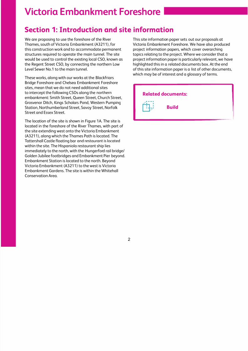
We are proposing to use the foreshore of the River
Thames, south of Victoria Embankment (A3211), forthis construction work and to accommodate permanent
structures required to operate the main tunnel. The site
would be used to control the existing local CSO, known as
the Regent Street CSO, by connecting the northern Low
Level Sewer No.1 to the main tunnel.
These works, along with our works at the Blackfriars
Bridge Foreshore and Chelsea Embankment Foreshore
sites, mean that we do not need additional sitesto intercept the following CSOs along the northern
embankment: Smith Street, Queen Street, Church Street,
Grosvenor Ditch, Kings Scholars Pond, Western Pumping
Station, Northumberland Street, Savoy Street, Norfolk
Street and Essex Street.
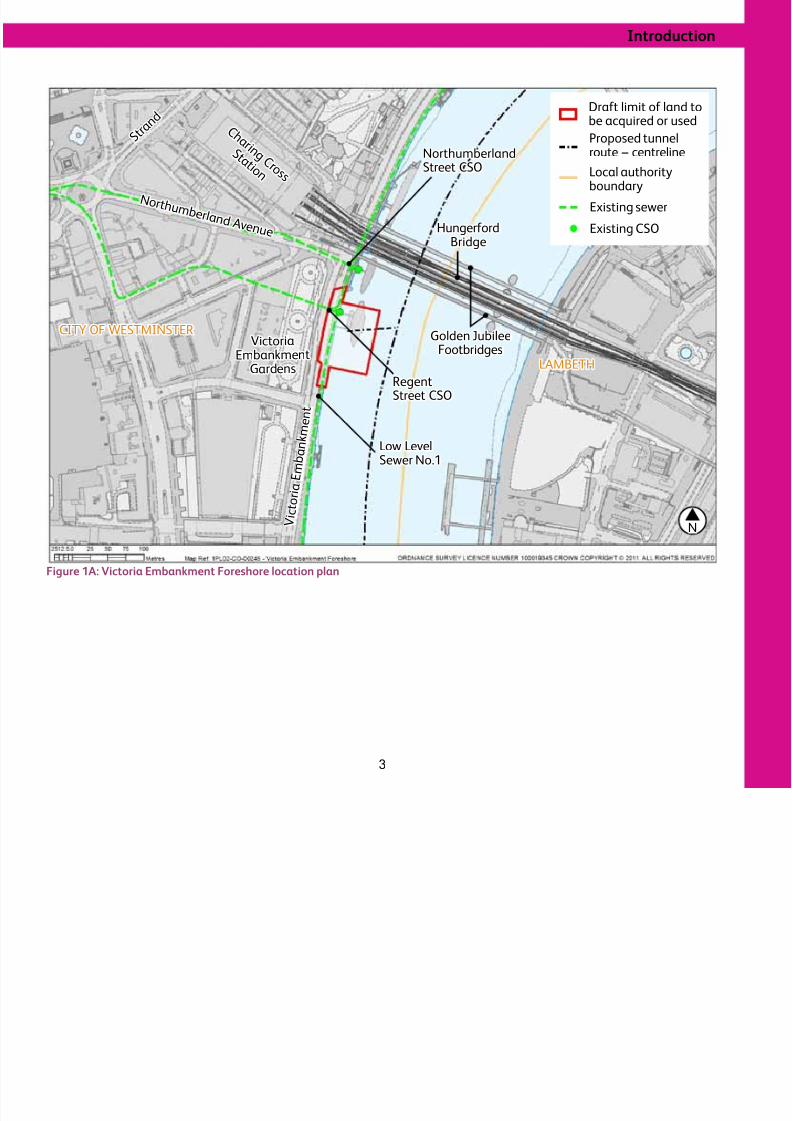
The location of the site is shown in Figure 1A. The site is
located in the foreshore of the River Thames, with part of
the site extending west onto the Victoria Embankment(A3211), along which the Thames Path is located. The
Tattershall Castle floating bar and restaurant is located
within the site. The Hispaniola restaurant ship lies
immediately to the north, with the Hungerford rail bridge/
Golden Jubilee footbridges and Embankment Pier beyond.
Embankment Station is located to the north. Beyond
Victoria Embankment (A3211) to the west is Victoria
Embankment Gardens. The site is within the Whitehall
Conservation Area.
This site information paper sets out our proposals at
Victoria Embankment Foreshore. We have also producedproject information papers, which cover overarching
topics relating to the project. Where we consider that a
project information paper is particularly relevant, we have
highlighted this in a related documents box. At the end
of this site information paper is a list of other documents,
which may be of interest and a glossary of terms.
8/3/2019 P2 Victoria Embankment Foreshore SIP
http://slidepdf.com/reader/full/p2-victoria-embankment-foreshore-sip 3/28
Introduction
3
Figure 1A: Victoria Embankment Foreshore location plan
Victoria
Embankment
Gardens
Golden JubileeFootbridges
C h a r i n g C r o s s
S t a t i o n
S t r a n
d
V i c
t o r i a
E m
b a n
k m e n
t
N o r t h u m b e r l a n d Av e n u e HungerfordBridge
Low LevelSewer No.1
RegentStreet CSO
NorthumberlandStreet CSO
N
CITY OF WESTMINSTER
LAMBETH
Local authorityboundary
Draft limit of land tobe acquired or used
Proposed tunnelroute – centreline
Existing sewer
Existing CSO
8/3/2019 P2 Victoria Embankment Foreshore SIP
http://slidepdf.com/reader/full/p2-victoria-embankment-foreshore-sip 4/28
Victoria Embankment Foreshore
4
Related documents:
Q&A Consultation
Site selection
How we chose this site
What we proposed at phase one consultationThrough our site selection process, we identified two
possible shortlisted sites to control the Regent Street
CSO by linking the northern Low Level Sewer No.1 to
the main tunnel. At phase one consultation, which was
held between September 2010 and January 2011, we
presented these sites:
•Victoria Embankment Gardens
•Victoria Embankment Foreshore.
Victoria Embankment Foreshore was identified as our
preferred site at phase one consultation.
What we are proposing at phase two consultation
We have considered the comments from phase one
consultation, feedback from ongoing engagement and
new information; and undertaken further technical work.
We still consider that Victoria Embankment Foreshore
should be our preferred site because the use of the
foreshore is preferable to the temporary loss of and the
potential permanent effects upon the Grade II listed
Victoria Embankment Gardens.
8/3/2019 P2 Victoria Embankment Foreshore SIP
http://slidepdf.com/reader/full/p2-victoria-embankment-foreshore-sip 5/28
Construction
C on s t r u c t i on
5
Section 2: Construction
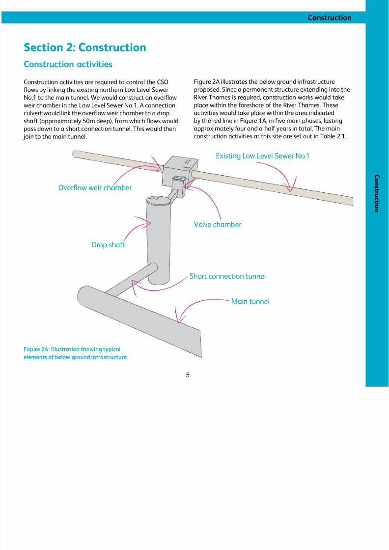
Construction activitiesConstruction activities are required to control the CSO
flows by linking the existing northern Low Level Sewer
No.1 to the main tunnel. We would construct an overflow
weir chamber in the Low Level Sewer No.1. A connection
culvert would link the overflow weir chamber to a drop
shaft (approximately 50m deep), from which flows would
pass down to a short connection tunnel. This would then
join to the main tunnel.
Figure 2A illustrates the below ground infrastructure
proposed. Since a permanent structure extending into the
River Thames is required, construction works would take
place within the foreshore of the River Thames. These
activities would take place within the area indicated
by the red line in Figure 1A, in five main phases, lasting
approximately four and a half years in total. The main
construction activities at this site are set out in Table 2.1.
Main tunnel
Short connection tunnel
Drop shaf t
Valve chamber
Existing Low Level Sewer No.1
Overfowweirchamber
Figure 2A: Illustration showing typical
elements of below ground infrastructure
8/3/2019 P2 Victoria Embankment Foreshore SIP
http://slidepdf.com/reader/full/p2-victoria-embankment-foreshore-sip 6/28
Victoria Embankment Foreshore
6
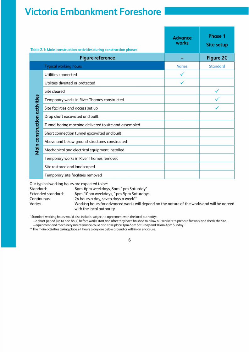
Advance
works
Phase 1
Site setup
Figure reference – Figure 2C
Typical working hours Varies Standard
M a i n c o n s t r u c t i o n a c t i v i t i e s
Utilities connected ü
Utilities diverted or protected ü
Site cleared ü
Temporary works in River Thames constructed ü
Site facilities and access set up ü
Drop shaft excavated and built
Tunnel boring machine delivered to site and assembled
Short connection tunnel excavated and built
Above and below ground structures constructed
Mechanical and electrical equipment installed
Temporary works in River Thames removed
Site restored and landscaped
Temporary site facilities removed
Table 2.1: Main construction activities during construction phases
Our typical working hours are expected to be:
Standard: 8am-6pm weekdays, 8am-1pm Saturday*
Extended standard: 6pm-10pm weekdays, 1pm-5pm Saturdays
Continuous: 24 hours a day, seven days a week**
Varies: Working hours for advanced works will depend on the nature of the works and will be agreed
with the local authority
* Standard working hours would also include, subject to agreement with the local authority:– a short period (up to one hour) before works start and after they have finished to allow our workers to prepare for work and check the site.
– equipment and machinery maintenance could also take place 1pm-5pm Saturday and 10am-4pm Sunday.
** The main activities taking place 24 hours a day are below ground or within an enclosure.
8/3/2019 P2 Victoria Embankment Foreshore SIP
http://slidepdf.com/reader/full/p2-victoria-embankment-foreshore-sip 7/28
Construction
7
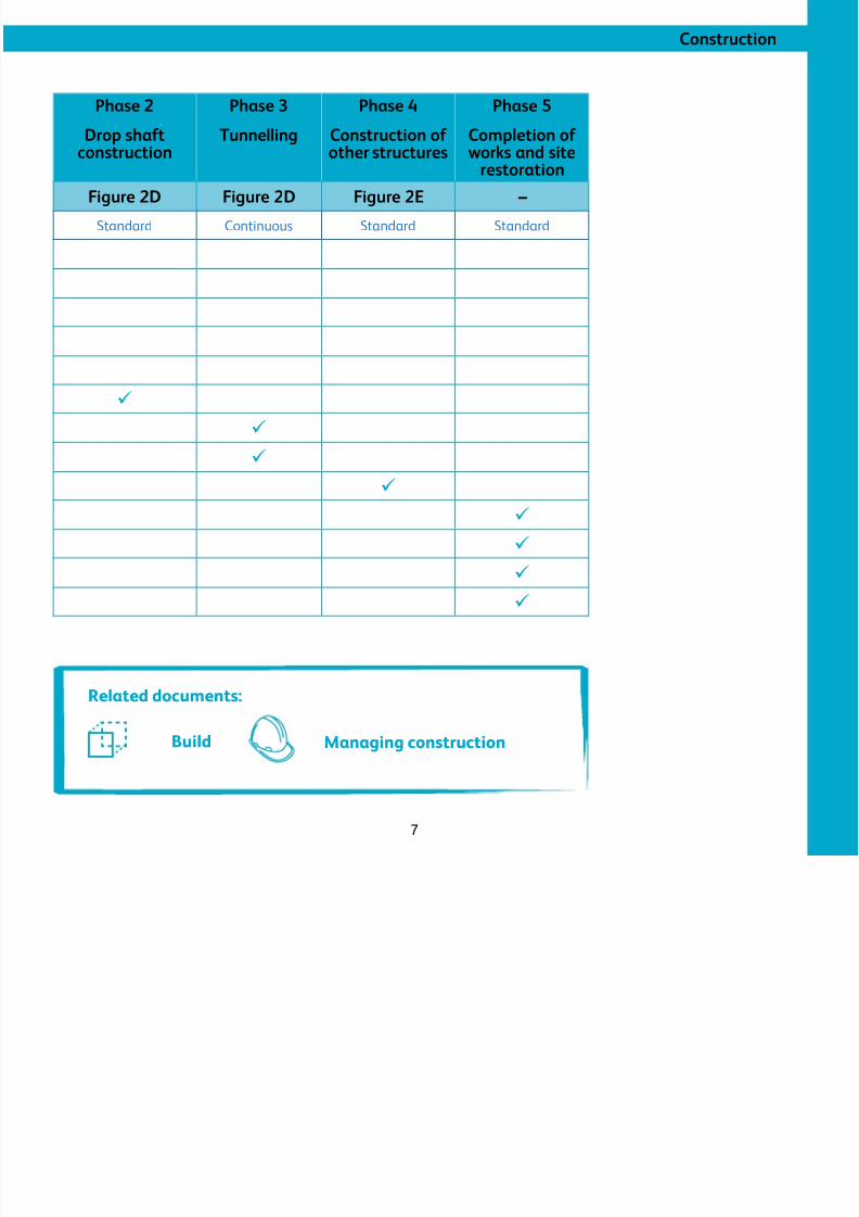
Phase 2
Drop shaft
construction
Phase 3
Tunnelling
Phase 4
Construction of
other structures
Phase 5
Completion of
works and siterestoration
Figure 2D Figure 2D Figure 2E –
Standard Continuous Standard Standard
ü
ü
ü
ü
ü
ü
ü
ü
Related documents:
Build Managing construction
8/3/2019 P2 Victoria Embankment Foreshore SIP
http://slidepdf.com/reader/full/p2-victoria-embankment-foreshore-sip 8/28
Victoria Embankment Foreshore
8
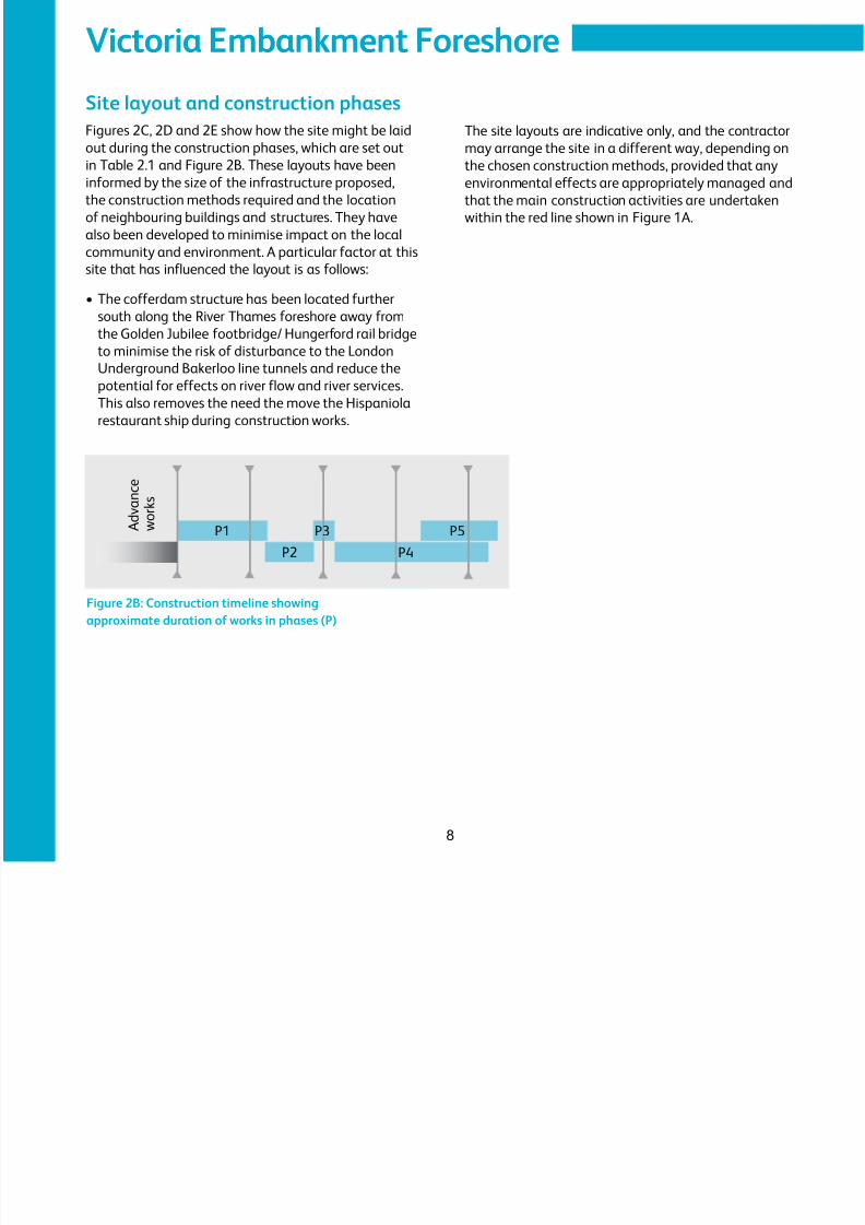
Site layout and construction phasesFigures 2C, 2D and 2E show how the site might be laid
out during the construction phases, which are set outin Table 2.1 and Figure 2B. These layouts have been
informed by the size of the infrastructure proposed,
the construction methods required and the location
of neighbouring buildings and structures. They have
also been developed to minimise impact on the local
community and environment. A particular factor at this
site that has influenced the layout is as follows:
•
The cofferdam structure has been located furthersouth along the River Thames foreshore away from
the Golden Jubilee footbridge/ Hungerford rail bridge
to minimise the risk of disturbance to the London
Underground Bakerloo line tunnels and reduce the
potential for effects on river flow and river services.
This also removes the need the move the Hispaniola
restaurant ship during construction works.
P1 P3
P2 P4
P5 A d v a n c e
w o r k s
Figure 2B: Construction timeline showingapproximate duration of works in phases (P)
The site layouts are indicative only, and the contractor
may arrange the site in a different way, depending onthe chosen construction methods, provided that any
environmental effects are appropriately managed and
that the main construction activities are undertaken
within the red line shown in Figure 1A.
8/3/2019 P2 Victoria Embankment Foreshore SIP
http://slidepdf.com/reader/full/p2-victoria-embankment-foreshore-sip 9/28
Construction
9
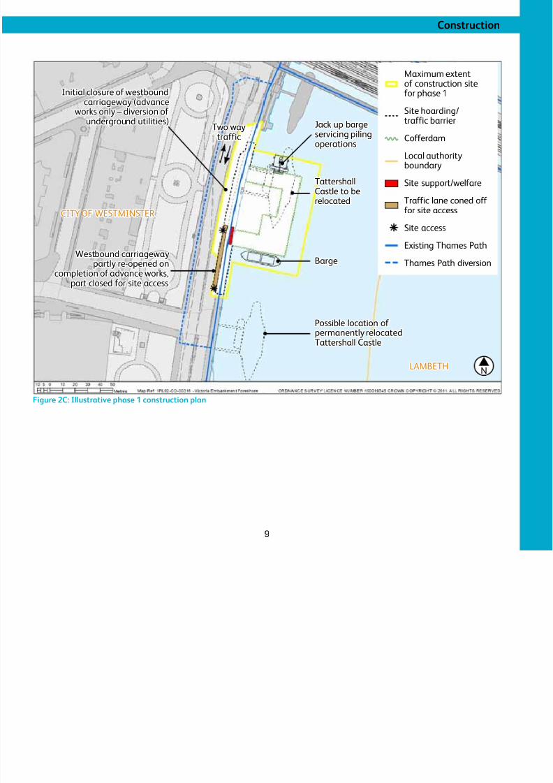
Figure 2C: Illustrative phase 1 construction plan
Jack up bargeservicing pilingoperations
Two waytraffic
Initial closure of westboundcarriageway (advance
works only – diversion of underground utilities)
Tattershall
Castle to berelocated
Possible location of permanently relocatedTattershall Castle
Westbound carriagewaypartly re-opened on
completion of advance works,part closed for site access
Barge
N
Maximum extentof construction site
for phase 1Site hoarding/traffic barrier
Cofferdam
Local authorityboundary
Site support/welfare
Traffic lane coned off for site access
Site access
Existing Thames Path
Thames Path diversion
CITY OF WESTMINSTER
LAMBETH
8/3/2019 P2 Victoria Embankment Foreshore SIP
http://slidepdf.com/reader/full/p2-victoria-embankment-foreshore-sip 10/28
Victoria Embankment Foreshore
10
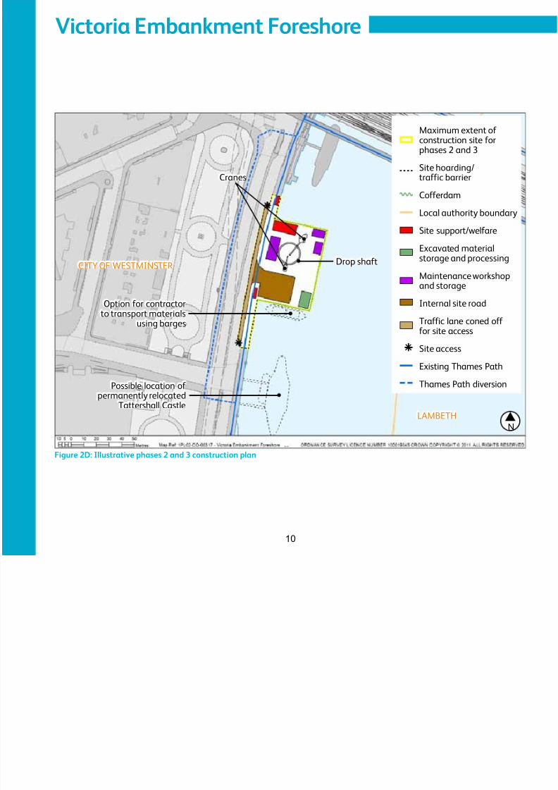
Figure 2D: Illustrative phases 2 and 3 construction plan
N
Option for contractorto transport materials
using barges
Cranes
Drop shaft
Maximum extent of construction site forphases 2 and 3
Site hoarding/traffic barrier
Cofferdam
Local authority boundary
Site support/welfare
Excavated materialstorage and processing
Maintenance workshopand storage
Internal site road
Traffic lane coned off for site access
Site access
Existing Thames Path
Thames Path diversion
CITY OF WESTMINSTER
LAMBETH
Possible location of permanently relocated
Tattershall Castle
8/3/2019 P2 Victoria Embankment Foreshore SIP
http://slidepdf.com/reader/full/p2-victoria-embankment-foreshore-sip 11/28
Construction
11
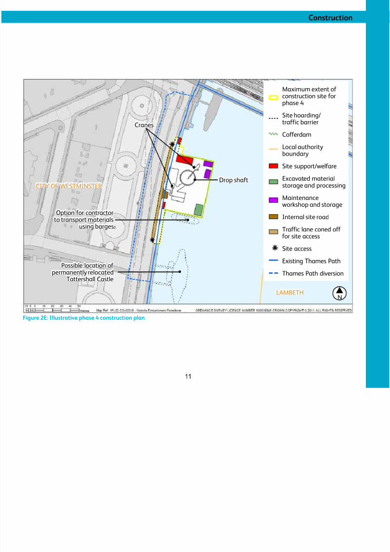
Figure 2E: Illustrative phase 4 construction plan
[Tames Water to provide plan]
N
Option for contractorto transport materials
using barges
Cranes
Drop shaft
Maximum extent of construction site forphase 4
Site hoarding/traffic barrier
CofferdamLocal authorityboundary
Site support/welfare
Excavated materialstorage and processing
Maintenance
workshop and storage
Internal site road
Traffic lane coned off for site access
Site access
Existing Thames Path
Thames Path diversion
CITY OF WESTMINSTER
LAMBETH
Possible location of
permanently relocatedTattershall Castle
8/3/2019 P2 Victoria Embankment Foreshore SIP
http://slidepdf.com/reader/full/p2-victoria-embankment-foreshore-sip 12/28
Victoria Embankment Foreshore
12
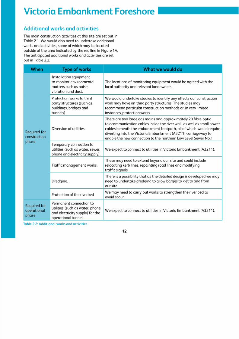
Additional works and activitiesThe main construction activities at this site are set out in
Table 2.1. We would also need to undertake additionalworks and activities, some of which may be located
outside of the area indicated by the red line in Figure 1A.
The anticipated additional works and activities are set
out in Table 2.2.
When Type of works What we would do
Required for
construction
phase
Installation equipment
to monitor environmental
matters such as noise,
vibration and dust.
The locations of monitoring equipment would be agreed with the
local authority and relevant landowners.
Protection works to third
party structures (such as
buildings, bridges and
tunnels).
We would undertake studies to identify any effects our construction
work may have on third party structures. The studies may
recommend particular construction methods or, in very limited
instances, protection works.
Diversion of utilities.
There are two large gas mains and approximately 20 fibre optic
telecommunication cables inside the river wall, as well as small power
cables beneath the embankment footpath, all of which would require
diverting into the Victoria Embankment (A3211) carriageway to
enable the new connection to the northern Low Level Sewer No.1.
Temporary connection to
utilities (such as water, sewer,
phone and electricity supply).
We expect to connect to utilities in Victoria Embankment (A3211).
Traffic management works.
These may need to extend beyond our site and could include
relocating kerb lines, repainting road lines and modifying
traffic signals.
Dredging.
There is a possibility that as the detailed design is developed we may
need to undertake dredging to allow barges to get to and from
our site.
Protection of the riverbedWe may need to carry out works to strengthen the river bed to
avoid scour.
Required for
operationalphase
Permanent connection to
utilities (such as water, phoneand electricity supply) for the
operational tunnel.
We expect to connect to utilities in Victoria Embankment (A3211).
Table 2.2: Additional works and activities
8/3/2019 P2 Victoria Embankment Foreshore SIP
http://slidepdf.com/reader/full/p2-victoria-embankment-foreshore-sip 13/28
Construction
13
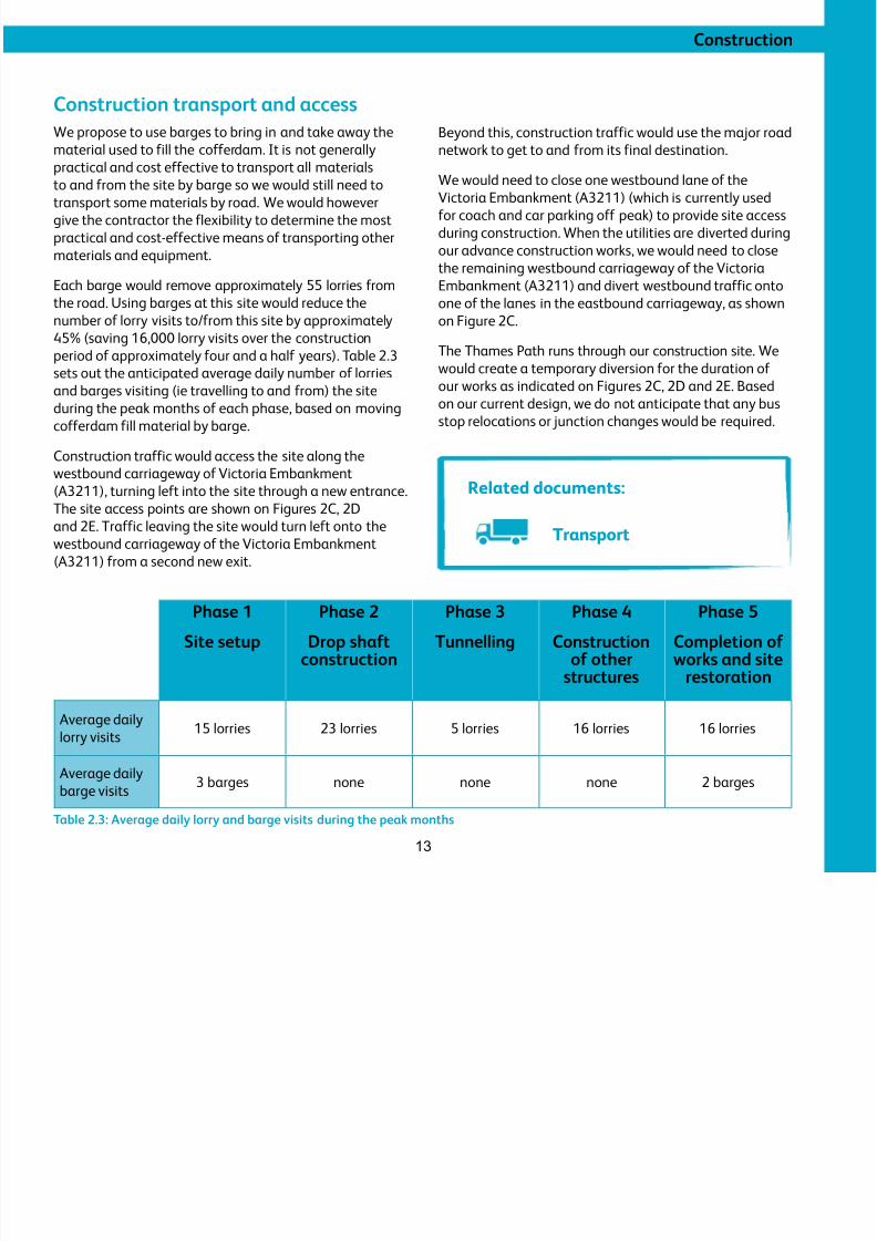
Construction transport and accessWe propose to use barges to bring in and take away the
material used to fill the cofferdam. It is not generallypractical and cost effective to transport all materials
to and from the site by barge so we would still need to
transport some materials by road. We would however
give the contractor the flexibility to determine the most
practical and cost-effective means of transporting other
materials and equipment.
Each barge would remove approximately 55 lorries from
the road. Using barges at this site would reduce thenumber of lorry visits to/from this site by approximately
45% (saving 16,000 lorry visits over the construction
period of approximately four and a half years). Table 2.3
sets out the anticipated average daily number of lorries
and barges visiting (ie travelling to and from) the site
during the peak months of each phase, based on moving
cofferdam fill material by barge.
Construction traffic would access the site along thewestbound carriageway of Victoria Embankment
(A3211), turning left into the site through a new entrance.
The site access points are shown on Figures 2C, 2D
and 2E. Traffic leaving the site would turn left onto the
westbound carriageway of the Victoria Embankment
(A3211) from a second new exit.
Beyond this, construction traffic would use the major road
network to get to and from its final destination.We would need to close one westbound lane of the
Victoria Embankment (A3211) (which is currently used
for coach and car parking off peak) to provide site access
during construction. When the utilities are diverted during
our advance construction works, we would need to close
the remaining westbound carriageway of the Victoria
Embankment (A3211) and divert westbound traffic onto
one of the lanes in the eastbound carriageway, as shownon Figure 2C.
The Thames Path runs through our construction site. We
would create a temporary diversion for the duration of
our works as indicated on Figures 2C, 2D and 2E. Based
on our current design, we do not anticipate that any bus
stop relocations or junction changes would be required.
Phase 1Site setup
Phase 2Drop shaft
construction
Phase 3Tunnelling
Phase 4Construction
of otherstructures
Phase 5Completion of works and site
restoration
Average daily
lorry visits15 lorries 23 lorries 5 lorries 16 lorries 16 lorries
Average dailybarge visits
3 barges none none none 2 barges
Table 2.3: Average daily lorry and barge visits during the peak months
Related documents:
Transport
8/3/2019 P2 Victoria Embankment Foreshore SIP
http://slidepdf.com/reader/full/p2-victoria-embankment-foreshore-sip 14/28
Victoria Embankment Foreshore
14
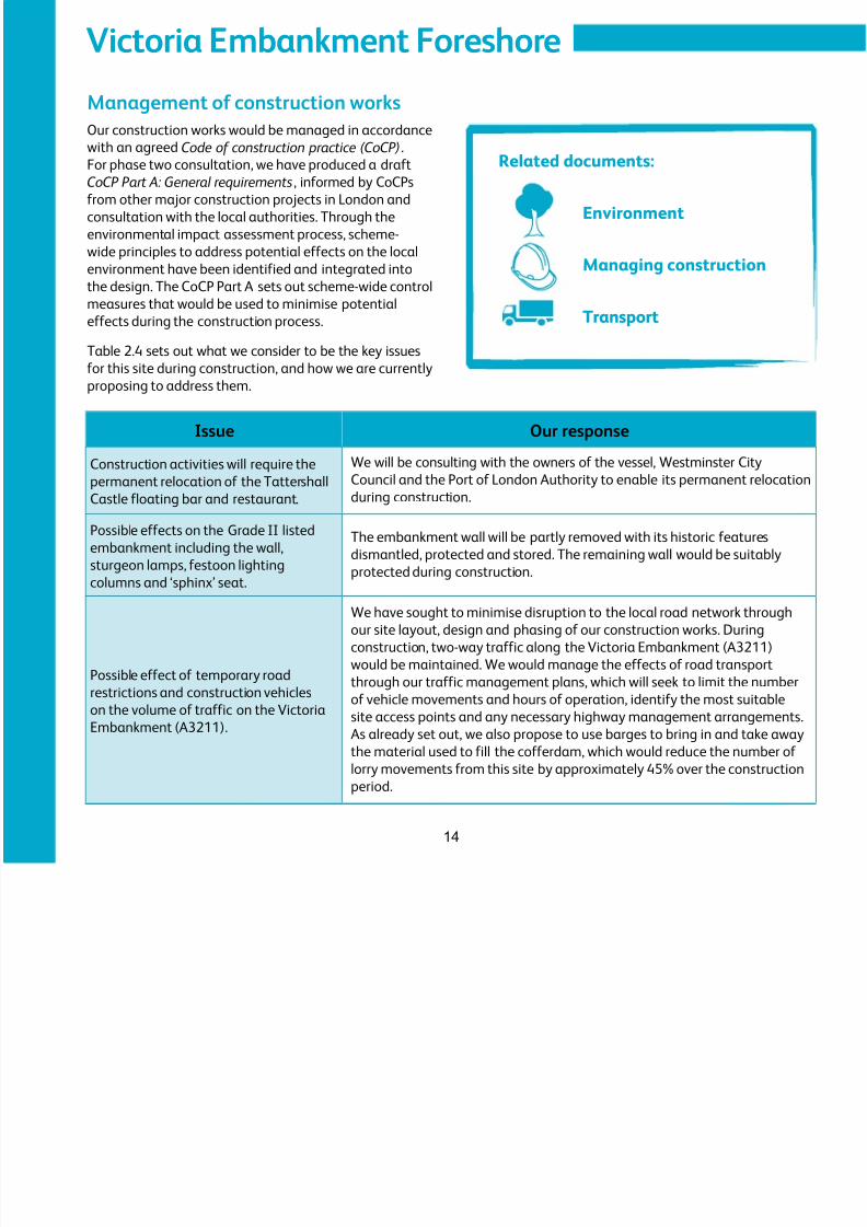
Management of construction worksOur construction works would be managed in accordance
with an agreed Code of construction practice (CoCP).For phase two consultation, we have produced a draft
CoCP Part A: General requirements, informed by CoCPs
from other major construction projects in London and
consultation with the local authorities. Through the
environmental impact assessment process, scheme-
wide principles to address potential effects on the local
environment have been identified and integrated into
the design. The CoCP Part A sets out scheme-wide control
measures that would be used to minimise potentialeffects during the construction process.
Table 2.4 sets out what we consider to be the key issues
for this site during construction, and how we are currently
proposing to address them.
Issue Our response
Construction activities will require thepermanent relocation of the Tattershall
Castle floating bar and restaurant.
We will be consulting with the owners of the vessel, Westminster CityCouncil and the Port of London Authority to enable its permanent relocation
during construction.
Possible effects on the Grade II listed
embankment including the wall,
sturgeon lamps, festoon lighting
columns and ‘sphinx’ seat.
The embankment wall will be partly removed with its historic features
dismantled, protected and stored. The remaining wall would be suitably
protected during construction.
Possible effect of temporary road
restrictions and construction vehicles
on the volume of traffic on the Victoria
Embankment (A3211).
We have sought to minimise disruption to the local road network throughour site layout, design and phasing of our construction works. During
construction, two-way traffic along the Victoria Embankment (A3211)
would be maintained. We would manage the effects of road transport
through our traffic management plans, which will seek to limit the number
of vehicle movements and hours of operation, identify the most suitable
site access points and any necessary highway management arrangements.
As already set out, we also propose to use barges to bring in and take away
the material used to fill the cofferdam, which would reduce the number of
lorry movements from this site by approximately 45% over the construction
period.
Related documents:
Environment
Managing construction
Transport
8/3/2019 P2 Victoria Embankment Foreshore SIP
http://slidepdf.com/reader/full/p2-victoria-embankment-foreshore-sip 15/28
Construction
15
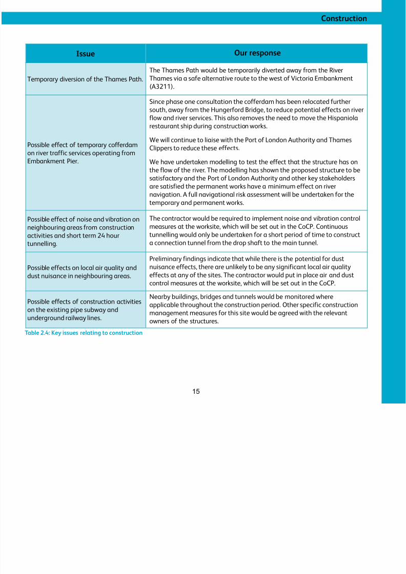
Issue Our response
Temporary diversion of the Thames Path.The Thames Path would be temporarily diverted away from the RiverThames via a safe alternative route to the west of Victoria Embankment
(A3211).
Possible effect of temporary cofferdamon river traffic services operating from
Embankment Pier.
Since phase one consultation the cofferdam has been relocated further
south, away from the Hungerford Bridge, to reduce potential effects on river
flow and river services. This also removes the need to move the Hispaniola
restaurant ship during construction works.
We will continue to liaise with the Port of London Authority and Thames
Clippers to reduce these effects.
We have undertaken modelling to test the effect that the structure has on
the flow of the river. The modelling has shown the proposed structure to be
satisfactory and the Port of London Authority and other key stakeholders
are satisfied the permanent works have a minimum effect on river
navigation. A full navigational risk assessment will be undertaken for the
temporary and permanent works.
Possible effect of noise and vibration on
neighbouring areas from construction
activities and short term 24 hour
tunnelling.
The contractor would be required to implement noise and vibration control
measures at the worksite, which will be set out in the CoCP. Continuous
tunnelling would only be undertaken for a short period of time to construct
a connection tunnel from the drop shaft to the main tunnel.
Possible effects on local air quality and
dust nuisance in neighbouring areas.
Preliminary findings indicate that while there is the potential for dust
nuisance effects, there are unlikely to be any significant local air quality
effects at any of the sites. The contractor would put in place air and dust
control measures at the worksite, which will be set out in the CoCP.
Possible effects of construction activities
on the existing pipe subway and
underground railway lines.
Nearby buildings, bridges and tunnels would be monitored where
applicable throughout the construction period. Other specific construction
management measures for this site would be agreed with the relevant
owners of the structures.
Table 2.4: Key issues relating to construction
Vi t i E b k t F h
8/3/2019 P2 Victoria Embankment Foreshore SIP
http://slidepdf.com/reader/full/p2-victoria-embankment-foreshore-sip 16/28
Victoria Embankment Foreshore
16
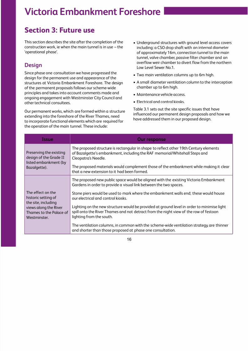
Section 3: Future use
This section describes the site after the completion of the
construction work, ie when the main tunnel is in use – the
‘operational phase’.
Design
Since phase one consultation we have progressed the
design for the permanent use and appearance of the
structures at Victoria Embankment Foreshore. The design
of the permanent proposals follows our scheme-wideprinciples and takes into account comments made and
ongoing engagement with Westminster City Council and
other technical consultees.
Our permanent works, which are formed within a structure
extending into the foreshore of the River Thames, need
to incorporate functional elements which are required for
the operation of the main tunnel. These include:
•
Underground structures with ground level access coversincluding: a CSO drop shaft with an internal diameter
of approximately 16m, connection tunnel to the main
tunnel, valve chamber, passive filter chamber and an
overflow weir chamber to divert flow from the northern
Low Level Sewer No.1.
•Two main ventilation columns up to 6m high.
•A small diameter ventilation column to the interception
chamber up to 6m high.•Maintenance vehicle access.
•Electrical and control kiosks.
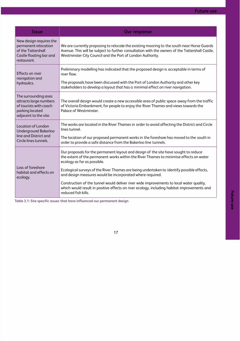
Table 3.1 sets out the site specific issues that have
influenced our permanent design proposals and how we
have addressed them in our proposed design.
Issue Our response
Preserving the existing
design of the Grade II
listed embankment (by
Bazalgette).
The proposed structure is rectangular in shape to reflect other 19th Century elements
of Bazalgette’s embankment, including the RAF memorial/Whitehall Steps and
Cleopatra’s Needle.
The proposed materials would complement those of the embankment while making it clear
that a new extension to it had been formed.
The effect on the
historic setting of
the site, including
views along the River
Thames to the Palace of
Westminster.
The proposed new public space would be aligned with the existing Victoria Embankment
Gardens in order to provide a visual link between the two spaces.
Stone piers would be used to mark where the embankment walls end; these would house
our electrical and control kiosks.
Lighting on the new structure would be provided at ground level in order to minimise light
spill onto the River Thames and not detract from the night view of the row of festoon
lighting from the south.
The ventilation columns, in common with the scheme-wide ventilation strategy, are thinner
and shorter than those proposed at phase one consultation.
8/3/2019 P2 Victoria Embankment Foreshore SIP
http://slidepdf.com/reader/full/p2-victoria-embankment-foreshore-sip 17/28
F u t ur e
u s e
Future use
17
Issue Our response
New design requires the
permanent relocation
of the Tattershall
Castle floating bar and
restaurant.
We are currently proposing to relocate the existing mooring to the south near Horse Guards
Avenue. This will be subject to further consultation with the owners of the Tattershall Castle,
Westminster City Council and the Port of London Authority.
Effects on river
navigation and
hydraulics.
Preliminary modelling has indicated that the proposed design is acceptable in terms of
river flow.
The proposals have been discussed with the Port of London Authority and other key
stakeholders to develop a layout that has a minimal effect on river navigation.
The surrounding area
attracts large numbers
of tourists with coach
parking located
adjacent to the site.
The overall design would create a new accessible area of public space away from the traffic
of Victoria Embankment, for people to enjoy the River Thames and views towards the
Palace of Westminster.
Location of LondonUnderground Bakerloo
line and District and
Circle lines tunnels.
The works are located in the River Thames in order to avoid affecting the District and Circle
lines tunnel.
The location of our proposed permanent works in the foreshore has moved to the south in
order to provide a safe distance from the Bakerloo line tunnels.
Loss of foreshore
habitat and effects on
ecology.
Our proposals for the permanent layout and design of the site have sought to reduce
the extent of the permanent works within the River Thames to minimise effects on water
ecology as far as possible.
Ecological surveys of the River Thames are being undertaken to identify possible effects,and design measures would be incorporated where required.
Construction of the tunnel would deliver river wide improvements to local water quality,
which would result in positive effects on river ecology, including habitat improvements and
reduced fish kills.
Table 3.1: Site specific issues that have influenced our permanent design
Victoria Embankment Foreshore
8/3/2019 P2 Victoria Embankment Foreshore SIP
http://slidepdf.com/reader/full/p2-victoria-embankment-foreshore-sip 18/28
Victoria Embankment Foreshore
18
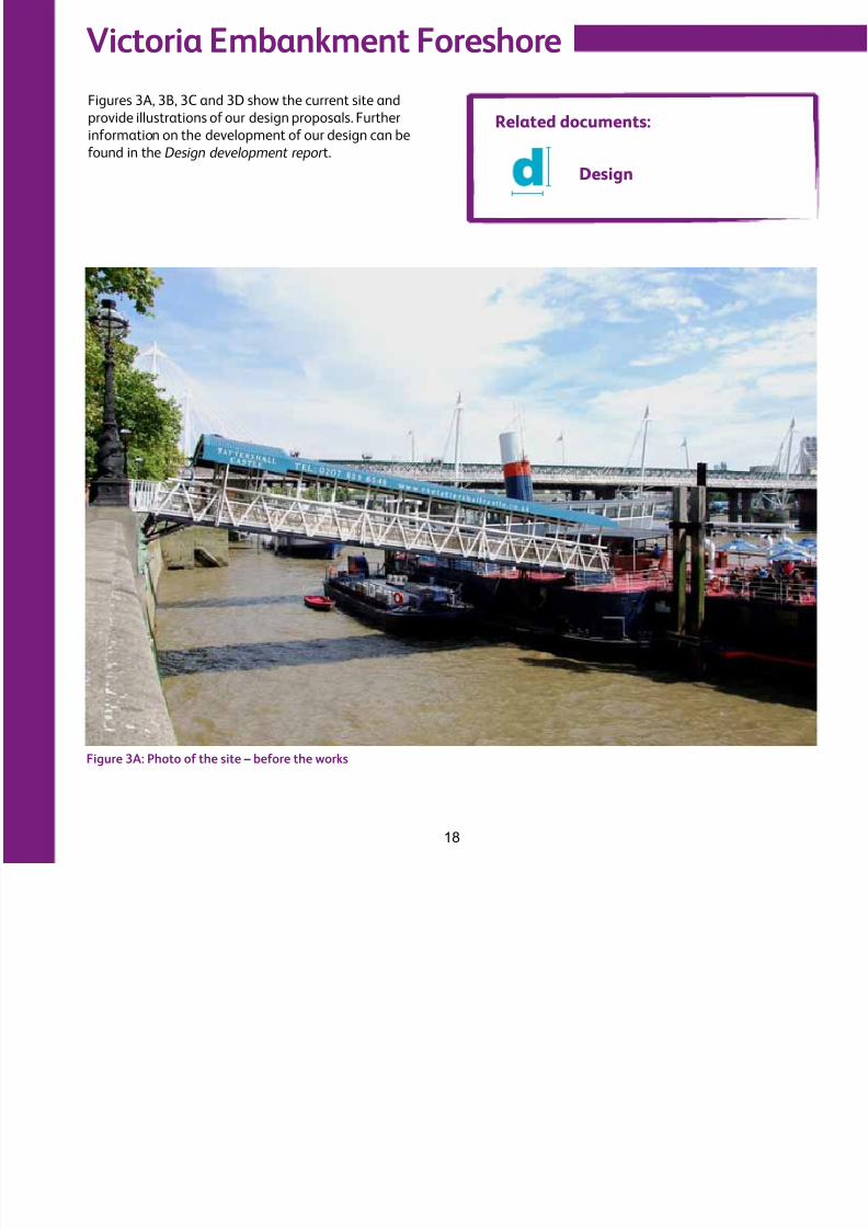
Figure 3A: Photo of the site – before the works
Figures 3A, 3B, 3C and 3D show the current site and
provide illustrations of our design proposals. Further
information on the development of our design can be
found in the Design development repor t.
Related documents:
Design
Future use
8/3/2019 P2 Victoria Embankment Foreshore SIP
http://slidepdf.com/reader/full/p2-victoria-embankment-foreshore-sip 19/28
Future use
19
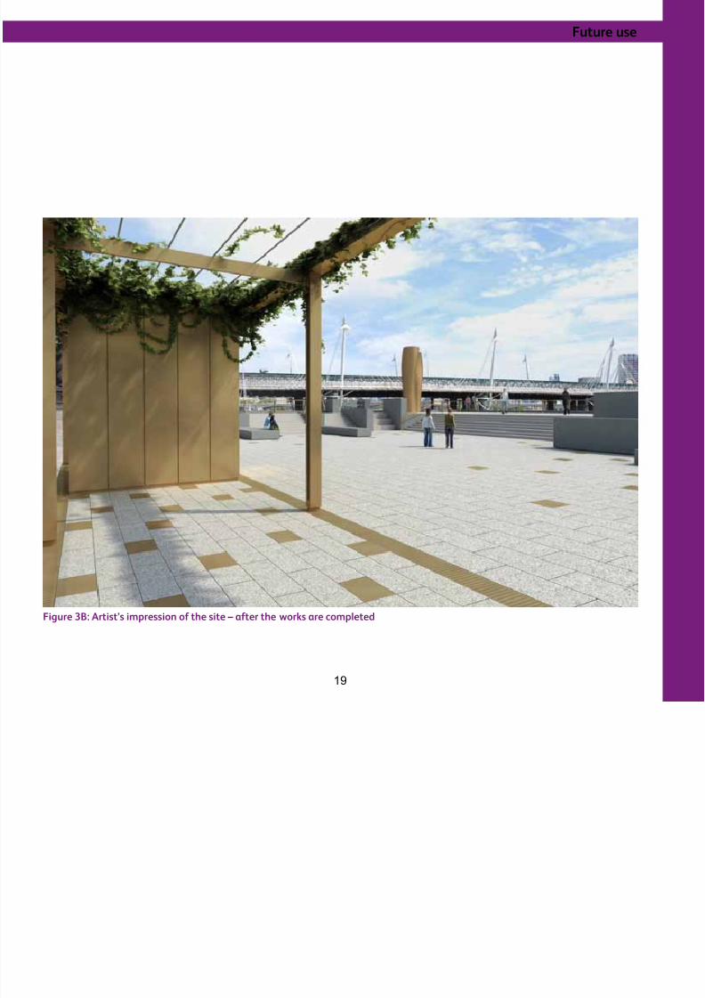
Figure 3B: Artist’s impression of the site – after the works are completed
Victoria Embankment Foreshore
8/3/2019 P2 Victoria Embankment Foreshore SIP
http://slidepdf.com/reader/full/p2-victoria-embankment-foreshore-sip 20/28
Victoria Embankment Foreshore
20
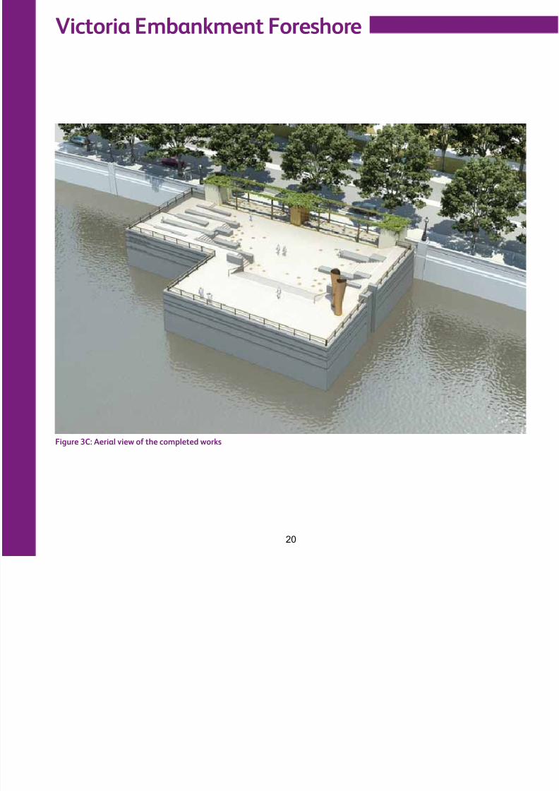
Figure 3C: Aerial view of the completed works
Future use
8/3/2019 P2 Victoria Embankment Foreshore SIP
http://slidepdf.com/reader/full/p2-victoria-embankment-foreshore-sip 21/28
Future use
21
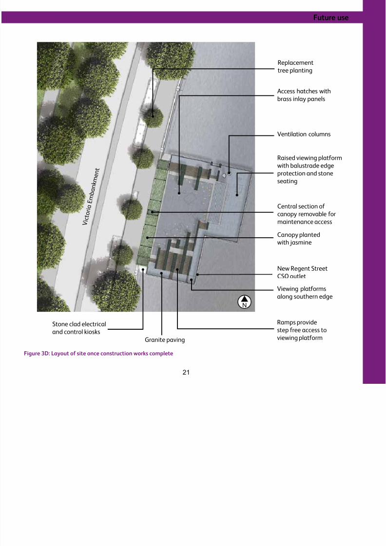
Figure 3D: Layout of site once construction works complete
Viewing platforms
along southern edge
Ramps provide
step free access to
viewing platformGranite paving
Stone clad electrical
and control kiosks
Central section of canopy removable for
maintenance access
Canopy planted
with jasmine
New Regent Street
CSO outlet
Ventilation columns
Access hatches with
brass inlay panels
Replacement
tree planting
Raised viewing platform
with balustrade edge
protection and stone
seating
V i c t o
r i a E
m b
a n k
m e n t
N
Victoria Embankment Foreshore
8/3/2019 P2 Victoria Embankment Foreshore SIP
http://slidepdf.com/reader/full/p2-victoria-embankment-foreshore-sip 22/28
Victoria Embankment Foreshore
22
Operation and maintenanceOnce the tunnel is operational, we would need access
to the site occasionally for inspection and maintenance
purposes. We expect to visit the site approximately
once every three to six months to carry out inspections
and maintenance of the ventilation and below ground
equipment. This is likely to involve a visit by staff in a
small van, and may take several hours.
Once every ten years, we expect to carry out a major
internal inspection of the tunnel and underground
structures. This is likely to involve a small team of
inspection staff, a small team of support crew and
two mobile cranes to lower the team into the shaft.
This is likely to take several days and we would require
temporary fencing around the shaft for safety and
security while the inspection takes place.
We may also need to make visits to the site for unplanned
maintenance or repairs, for example, if there is a blockage
or equipment failure. This may require the use of mobile
cranes and vans.
Permanent vehicular access would be from Victoria
Embankment (A3211).
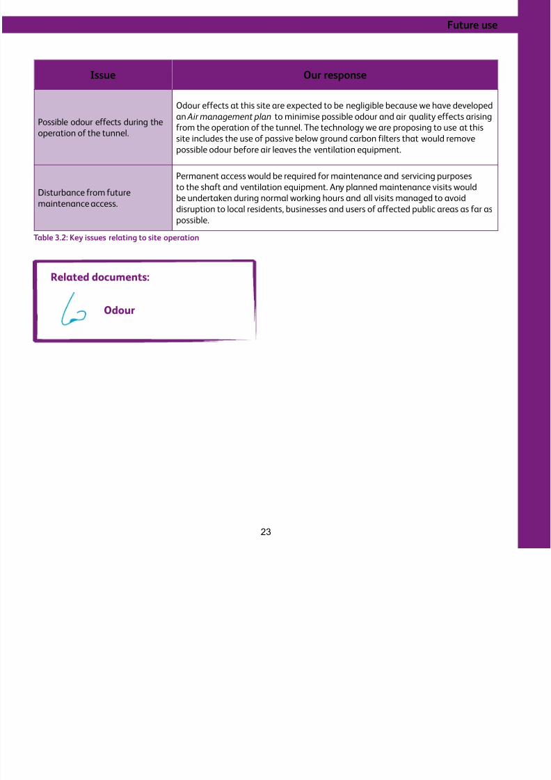
Management of operational effectsWe have undertaken technical work, including stakeholder
engagement, to assess and identify the key issues
associated with this site once it is operational. Table
3.2 summarises these issues and how we are currently
proposing to address them.
Future use
8/3/2019 P2 Victoria Embankment Foreshore SIP
http://slidepdf.com/reader/full/p2-victoria-embankment-foreshore-sip 23/28
23
Issue Our response
Possible odour effects during the
operation of the tunnel.
Odour effects at this site are expected to be negligible because we have developed
an Air management plan to minimise possible odour and air quality effects arising
from the operation of the tunnel. The technology we are proposing to use at this
site includes the use of passive below ground carbon filters that would remove
possible odour before air leaves the ventilation equipment.
Disturbance from futuremaintenance access.
Permanent access would be required for maintenance and servicing purposes
to the shaft and ventilation equipment. Any planned maintenance visits would
be undertaken during normal working hours and all visits managed to avoiddisruption to local residents, businesses and users of affected public areas as far as
possible.
Table 3.2: Key issues relating to site operation
Related documents:
Odour
Further information
8/3/2019 P2 Victoria Embankment Foreshore SIP
http://slidepdf.com/reader/full/p2-victoria-embankment-foreshore-sip 24/28
24
Further information
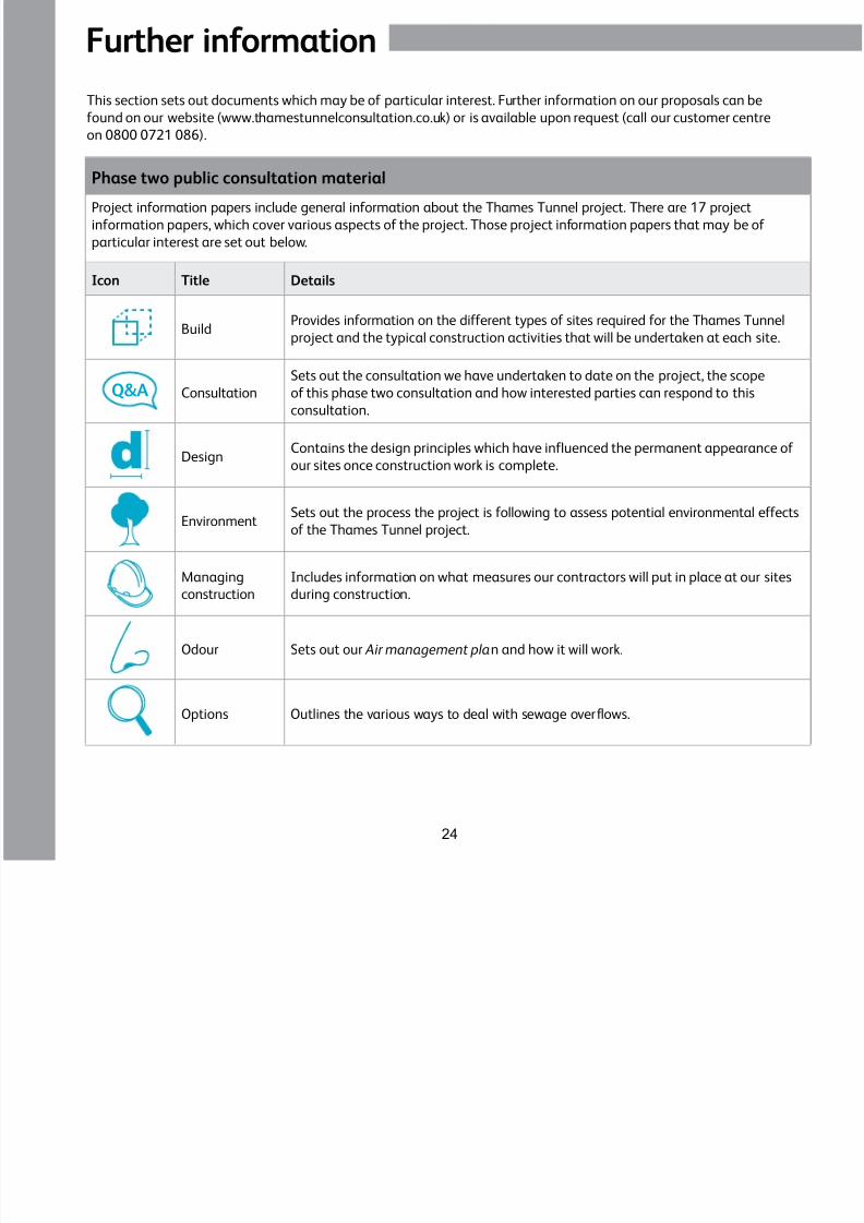
This section sets out documents which may be of particular interest. Further information on our proposals can be
found on our website (www.thamestunnelconsultation.co.uk) or is available upon request (call our customer centre
on 0800 0721 086).
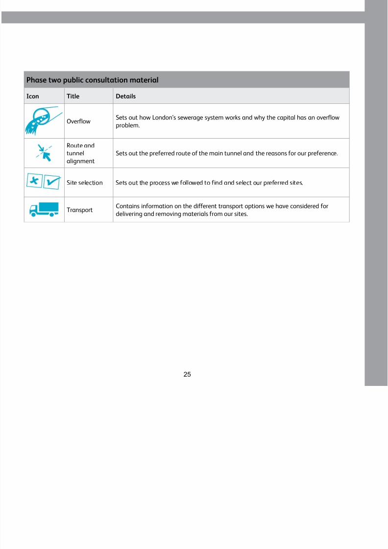
Phase two public consultation material
Project information papers include general information about the Thames Tunnel project. There are 17 project
information papers, which cover various aspects of the project. Those project information papers that may be of
particular interest are set out below.
Icon Title Details
Build
Provides information on the different types of sites required for the Thames Tunnel
project and the typical construction activities that will be undertaken at each site.
Q&A Consultation
Sets out the consultation we have undertaken to date on the project, the scope
of this phase two consultation and how interested parties can respond to this
consultation.
Design
Contains the design principles which have influenced the permanent appearance of
our sites once construction work is complete.
EnvironmentSets out the process the project is following to assess potential environmental effects
of the Thames Tunnel project.
Managing
construction
Includes information on what measures our contractors will put in place at our sites
during construction.
Odour Sets out our Air management plan and how it will work.
Options Outlines the various ways to deal with sewage overflows.
8/3/2019 P2 Victoria Embankment Foreshore SIP
http://slidepdf.com/reader/full/p2-victoria-embankment-foreshore-sip 25/28
Further information
8/3/2019 P2 Victoria Embankment Foreshore SIP
http://slidepdf.com/reader/full/p2-victoria-embankment-foreshore-sip 26/28
26
u t e o at o
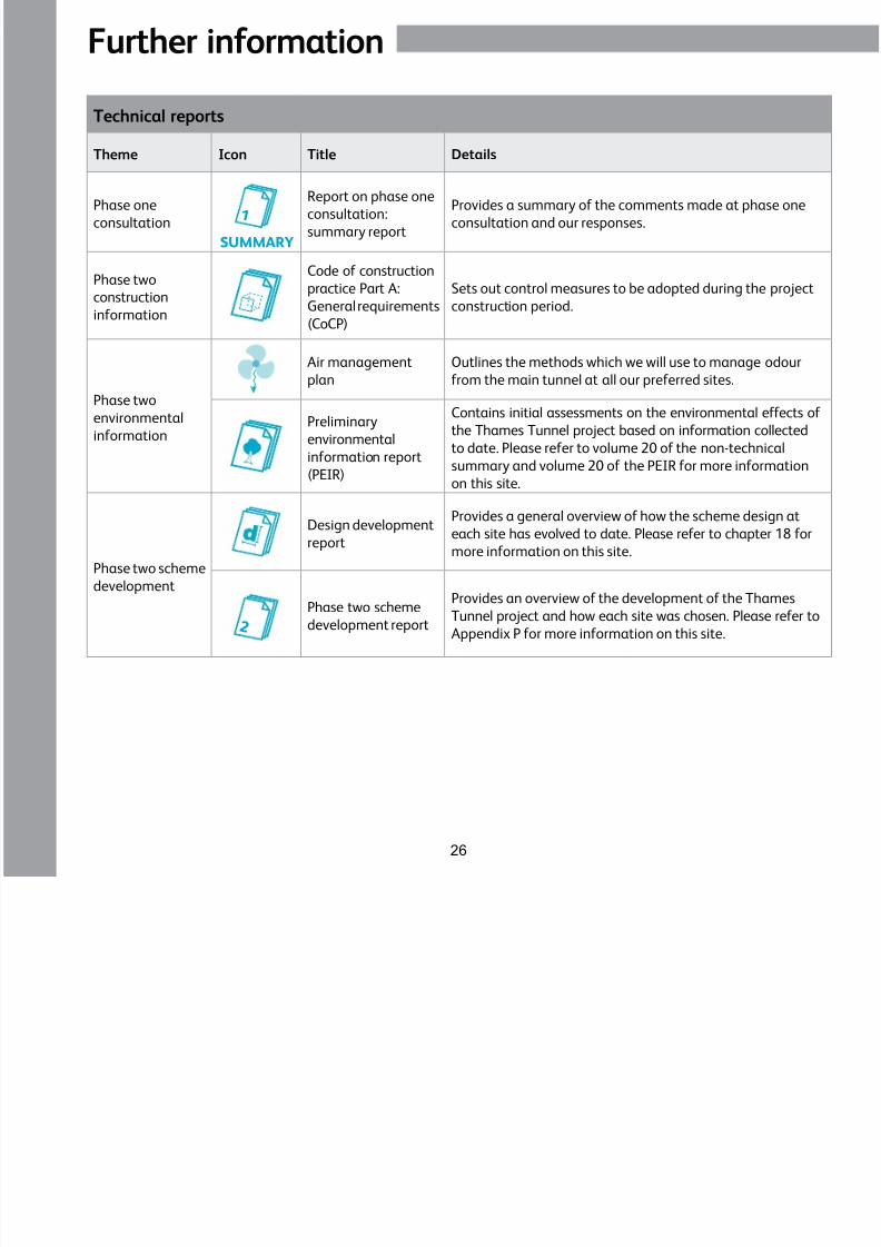
Technical reports
Theme Icon Title Details
Phase one
consultation1
SUMMARY
Report on phase one
consultation:
summary report
Provides a summary of the comments made at phase one
consultation and our responses.
Phase two
construction
information
Code of construction
practice Part A:
General requirements
(CoCP)
Sets out control measures to be adopted during the project
construction period.
Phase two
environmental
information
Air management
plan
Outlines the methods which we will use to manage odour
from the main tunnel at all our preferred sites.
Preliminary
environmental
information report
(PEIR)
Contains initial assessments on the environmental effects of
the Thames Tunnel project based on information collected
to date. Please refer to volume 20 of the non-technical
summary and volume 20 of the PEIR for more informationon this site.
Phase two scheme
development
Design development
report
Provides a general overview of how the scheme design at
each site has evolved to date. Please refer to chapter 18 for
more information on this site.
2
Phase two scheme
development report
Provides an overview of the development of the Thames
Tunnel project and how each site was chosen. Please refer to
Appendix P for more information on this site.
Site glossary
8/3/2019 P2 Victoria Embankment Foreshore SIP
http://slidepdf.com/reader/full/p2-victoria-embankment-foreshore-sip 27/28
27
g y
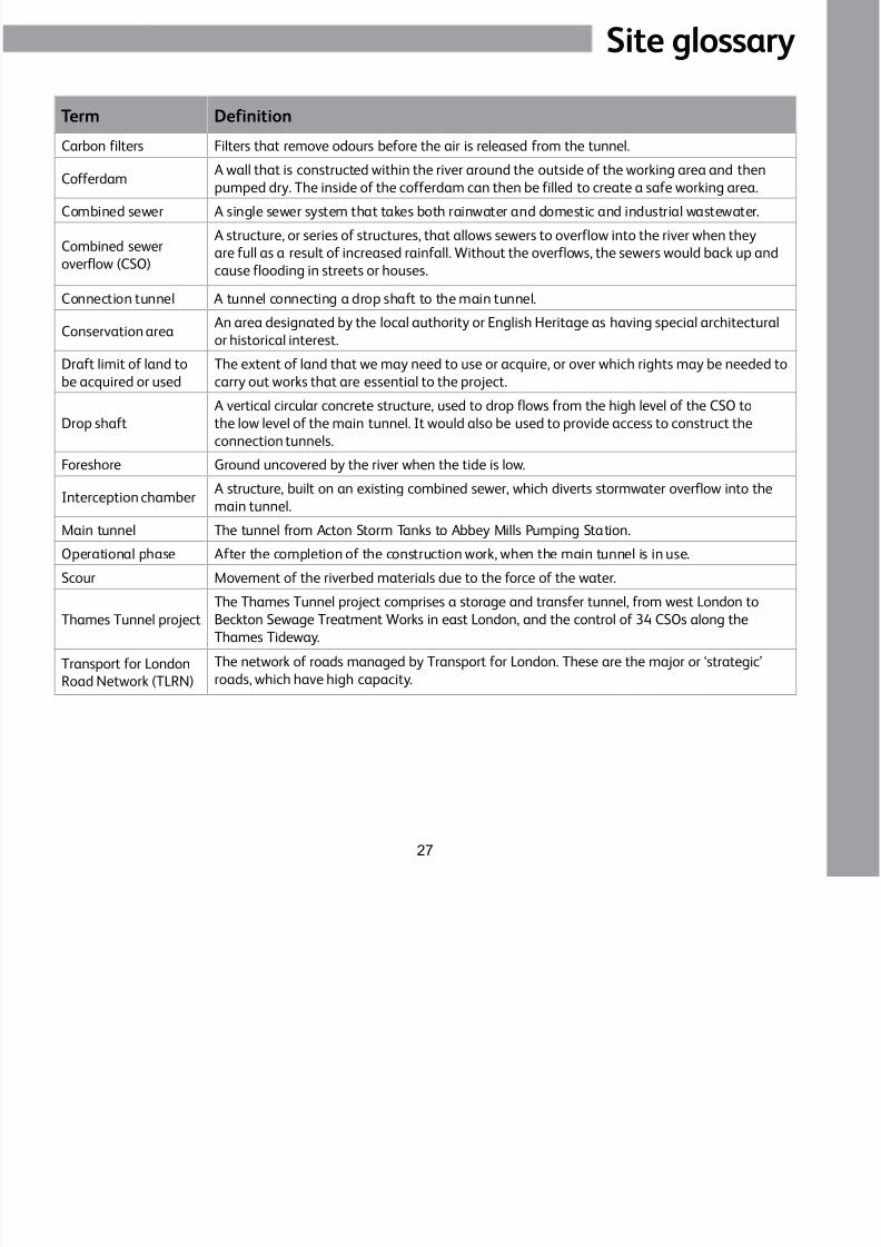
Term Definition
Carbon filters Filters that remove odours before the air is released from the tunnel.
CofferdamA wall that is constructed within the river around the outside of the working area and then
pumped dry. The inside of the cofferdam can then be filled to create a safe working area.
Combined sewer A single sewer system that takes both rainwater and domestic and industrial wastewater.
Combined sewer
overflow (CSO)
A structure, or series of structures, that allows sewers to overflow into the river when they
are full as a result of increased rainfall. Without the overflows, the sewers would back up and
cause flooding in streets or houses.
Connection tunnel A tunnel connecting a drop shaft to the main tunnel.
Conservation areaAn area designated by the local authority or English Heritage as having special architecturalor historical interest.
Draft limit of land to
be acquired or used
The extent of land that we may need to use or acquire, or over which rights may be needed to
carry out works that are essential to the project.
Drop shaft
A vertical circular concrete structure, used to drop flows from the high level of the CSO to
the low level of the main tunnel. It would also be used to provide access to construct the
connection tunnels.
Foreshore Ground uncovered by the river when the tide is low.
Interception chamberA structure, built on an existing combined sewer, which diverts stormwater overflow into the
main tunnel.
Main tunnel The tunnel from Acton Storm Tanks to Abbey Mills Pumping Station.
Operational phase After the completion of the construction work, when the main tunnel is in use.
Scour Movement of the riverbed materials due to the force of the water.
Thames Tunnel project
The Thames Tunnel project comprises a storage and transfer tunnel, from west London to
Beckton Sewage Treatment Works in east London, and the control of 34 CSOs along theThames Tideway.
Transport for London
Road Network (TLRN)
The network of roads managed by Transport for London. These are the major or ‘strategic’
roads, which have high capacity.

8/3/2019 P2 Victoria Embankment Foreshore SIP
http://slidepdf.com/reader/full/p2-victoria-embankment-foreshore-sip 28/28
Phase two consultation: Victoria Embankment Foreshore
For further information or to comment on ourproposals see our website:
www.thamestunnelconsultation.co.uk
110-ED-PNC-00000-000091
Autumn 2011
It is very important that you understand theinformation we have provided. If you needfurther information in another language,
braille, large print or audio format pleasecontact us on 0800 0721 086.