p40 agile p14n, p14d, p94v - ge grid solutions · 2017-05-12 · ge grid solutions p40 agile p14n,...
TRANSCRIPT
GEGrid Solutions
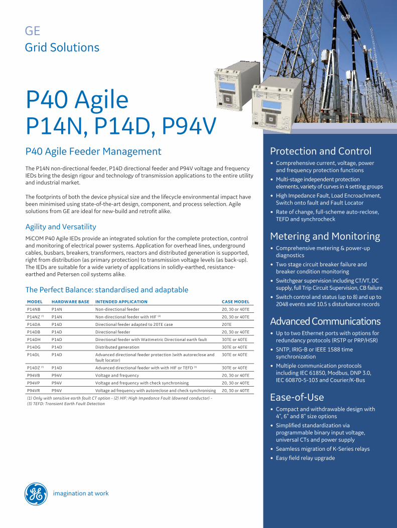
P40 Agile P14N, P14D, P94VP40 Agile Feeder ManagementThe P14N non-directional feeder, P14D directional feeder and P94V voltage and frequency IEDs bring the design rigour and technology of transmission applications to the entire utility and industrial market.
The footprints of both the device physical size and the lifecycle environmental impact have been minimised using state-of-the-art design, component, and process selection. Agile solutions from GE are ideal for new-build and retrofit alike.
Agility and VersatilityMiCOM P40 Agile IEDs provide an integrated solution for the complete protection, control and monitoring of electrical power systems. Application for overhead lines, underground cables, busbars, breakers, transformers, reactors and distributed generation is supported, right from distribution (as primary protection) to transmission voltage levels (as back-up). The IEDs are suitable for a wide variety of applications in solidly-earthed, resistance-earthed and Petersen coil systems alike.
The Perfect Balance: standardised and adaptable
Protection and Control� Comprehensive current, voltage, power
and frequency protection functions
� Multi-stage independent protection elements, variety of curves in 4 setting groups
� High Impedance Fault, Load Encroachment, Switch onto fault and Fault Locator
� Rate of change, full-scheme auto-reclose, TEFD and synchrocheck
Metering and Monitoring� Comprehensive metering & power-up
diagnostics
� Two stage circuit breaker failure and breaker condition monitoring
� Switchgear supervision including CT/VT, DC supply, full Trip Circuit Supervision, CB failure
� Switch control and status (up to 8) and up to 2048 events and 10.5 s disturbance records
Advanced Communications� Up to two Ethernet ports with options for
redundancy protocols (RSTP or PRP/HSR)
� SNTP, IRIG-B or IEEE 1588 time synchronization
� Multiple communication protocols including IEC 61850, Modbus, DNP 3.0, IEC 60870-5-103 and Courier/K-Bus
Ease-of-Use� Compact and withdrawable design with
4", 6" and 8" size options
� Simplified standardization via programmable binary input voltage, universal CTs and power supply
� Seamless migration of K-Series relays
� Easy field relay upgrade
imagination at work

GEGridSolutions.com
P40 Agile Feeder Management IEDs
Functional Overview.
2

P14DZ
Slot-in user labelling
P40 Agile Feeder Management IEDs
P40 Agile application scalability
Intuitive User InterfacesThe front-panel interface (shown in Figure 1) allows direct IED interaction. A USB front port offers enhanced access by laptop computers. Integrated user function keys and tri-colour programmable LEDs provide a cost-effective solution for control and annunciation. Numerous, optional, modern communication protocols, including IEC 61850, ensure interfacing to upper-level Supervisory, Control, Automation or Data Acquisition systems.
Environmental ResponsibilityThe IEDs are manufactured in a lead-free soldering process using lead-free components. Power dissipation is the lowest among comparable products, easing concern on station batteries. Even the product weight (including packaging) has been optimised to lessen the transit carbon footprint. All such actions boost the eco-responsibility demonstrated in the Product Environment Profile (PEP). The product does not require any resident battery.
The PEP shows claims for raw material depletion, energy depletion, water depletion, global warming potential, ozone depletion, photochemical ozone creation, air acidification, and hazardous waste production.
Quality Built-inQuality Built-In methodology is applied throughout the development and manufacturing of the IEDs. Parts stress analysis in R&D, rigorous component supplier selection, and a shipping carton compliant with ISTA protection requirements all are examples of best-practice to maximise long-life reliability. All circuit boards have harsh environmental coating, to resist moisture, salt, corrosive atmosphere and industrial ambient pollution – as standard. Circuit board production uses in-circuit tests, boundary scanning, built-in self-test, automated optical inspection, and X-ray scanning to achieve maximum test coverage.
Figure 2 depicts the software scalability of models, within the overall superset of the range functionality. The strong P40 family identity offers high customer familiarity, with minimal training requirements.
Cyber-SecurityThe sophistication of protection schemes, coupled with the advancement of technology, increasingly leads to devices and substations being interconnected with open networks, such as the internet or corporate-wide networks. This introduces a potential security risk making the grid vulnerable to cyber-attack, which could in turn lead to electrical outage. To secure communication within such environments, MiCOM P14N, P14D and P94V offer NERC-compliant cyber security.
GEGridSolutions.com
P40 Agile front panel interface
Asset Life ExtensionIn addition to new-build, P40 Agile IEDs can be used to refurbish legacy protection schemes. As MiCOM P14N and P14D are pin-to-pin compatible with KCGG14x and KCEG14x respectively, they can simply be plugged-in to the K relay cases for an easy upgrade. Draw-out substitute strategy along with setting conversion tool dramatically reduce the refurbishment time and cost.
HardwareAll models offer:
� Space-saving 4U height and 20TE (4"), 30TE (6") or 40TE (8") case sizes
� A front USB port and a rear RS485 port
� Power-up diagnostics and continuous self-monitoring
� Wide choice of opto-isolated binary inputs and output relays
� N/O (form A) and N/C (form B) watchdog contacts
� Field upgradeable to change the relay model avoiding costly hardware change via firmware upgrade
3
Additonalfour tri-colourprogrammable LEDs
Function keyswith tri-colour status LEDs
40TE (Size 8)
20TE (MiDOS Size 4)
30TE (Size 6)
P14DL
40TE (Size 8)
P14DG
P14DBP14DA
P14NZ
P14NB
P94VB
P94VRP94VP

* Refer to the Cortec code for possible configurations.
P40 Agile standard hardware (P14D)
GEGridSolutions.com
P40 Agile Feeder Management IEDs
Hardware Overview
4

There are two standard earth fault elements, each with four independent stages. The first is the EF1 ‘Measured’ element which operates from the quantity flowing directly into the relay’s earth (IN) input.
The second standard earth fault element (EF2) operates from a residual current that is derived internally by a mathematical summation of the three phase currents. The sensitive earth fault (SEF) order option fits a sensitive CT, designed for systems whose earth fault current is constrained. A core balance CT should be used to drive this SEF CT input.
Each of the three-phase overcurrent stages of P14D can be independently configured as directional protection and with specific characteristic angle (RCA) and boundaries.
P40 Agile Feeder Management IEDs
IEC and ANSI/IEEE inverse-time curve profiles
30TE and 40TE Models30TE and 40TE models can accommodate:
� An optional IRIG-B port for time synchronising
� An additional RS485/K-Bus port
� An optional single or redundant Ethernet port for IEC 61850or DNP3.0
� Optional additional binary I/O: up to 13 binary inputs and 12 binary outputs with options for TCS, depending on the Cortec code
� 40TE model supports 12 binary inputs and 12 binary outputs with TCS and Ethernet communication
.
Example hardware options available in case size 30TE
GEGridSolutions.com
All CT connections have integral shorting, when the IED is withdrawn from the case. This affords additional safety to personnel who may be working near live apparatus.
Feeder ProtectionEthernet, graphical programmable logic and proven protection, measurement and control algorithms from Grid Solutions’modular MiCOM P40 are native in the new range.
Phase and Earth Fault Overcurrent
Six independent stages are available for each phase overcurrent element. In addition to definite time and predefined IDMT curve selection, P14N and P14D support user programmable curves for customised operation and resetting.
The profile can be chosen to optimise the protection, without constraining the feeder’s loadability. If a standard curve is not suitable for the application, the user can program and upload a custom variant.
5
Special Applications
Load encroachment (blinder), cold load pick-up logic, second harmonic inrush blocking, broken conductor protection, RMS thermal overload protection, wattmetric earth fault, fault locator, auto reclose, switch onto fault, rate of change elements, and check synchronising are built-in depending on the selected model number.
High Impedance & Transient Earth Fault Detection (HIF & TEFD)
Innovative high impedance earth fault algorithms improve the detection of downed conductors which have fallen on surfaces with high resistivity (eg. sand, dry scrubland, trees). This helps the utility to save human lives, protect nearby animals and lessen the risk of vegetation fires caused by prolonged arcing. Prior to the advent of HIF, such faults may not have been detectable by conventional earth fault methods, due to the extremely low and/or sporadic current flow.
Transient earth fault detection benefits from an advanced and innovative algorithm to detect the direction of single phase faults in compensated power systems.

Voltage Vector Shift Protection
This function measures the instantaneous change in the three-phase voltage angle that occurs when the connection to the main supply network is lost. To provide stability, this element must be less sensitive than the rate of change of frequency element. However, it operates without any intentional time delay, providing fast tripping.
Transformer ProtectionP14N and P14D devices offer the required current protection with second harmonic blocking, thermal overload protection and instantaneous restricted earth fault element (REF). REF detects transformer winding earth faults, and may be configured as high impedance or low impedance biased differential. Negative sequence overcurrent protection can be set non-directional or directional (forward/reverse) and offers detection of remote phase-phase and phase earth faults.
Busbar Protection
Phase fault overcurrent element can be applied in a high impedance differential protection scheme for busbars, fitted with external stabilising resistors and non-linear resistors (Metrosils). This solution provides stability for through faults and proper operation for internal faults for single and split busbar arrangements. Alternatively, a peer-to-peer hard-wired or Ethernet scheme can achieve blocked overcurrent unit protection for busbars.
Load Shedding and RestorationNine stages each of frequency protection are available (except P14N). Each may measure in over-, under-, rate of change, frequency supervised rate of change or average rate of change mode.
The wide range of setting options permits application of any frequency based load shedding or islanding scheme. Four stages of rate of change of voltage protection elements are also available, which offer an alternative approach to implement load-shedding schemes.
Logic and Control CapabilitiesAll aspects of MiCOM P40, and MiCOM P40 Agile IED configuration are managed using the MiCOM S1 Agile software.
Typical current waveform trace recorded for a downed conductor
GEGridSolutions.com
P40 Agile Feeder Management IEDs
Wattmetric Directional Earth Fault (WDE)
An earth fault in an unearthed 3-phase system causes the phase voltage in the other two phases to increase. This in turn will cause arcing at the fault location. Many distribution systems use a Peterson coil to compensate, thus eliminating the arcing problem. The introduction of a Peterson coil creates difficulties for determining the direction of the fault. Standard directionalising techniques used by conventional feeder protection devices are not adequate. Wattmetric Directional Earthfault (WDE) is used in this scenario to protect compensated networks.
Distributed Generation Protection
Voltage Controlled and Voltage Restrained Overcurrent
Voltage-dependent protection boosts sensitivity and reduces tripping times for faults on weaker systems, such as those with a high prevalence of distributed generation. The timing characteristic can be set as either definite time or IDMT.
Power
Two stages of power protection are provided and each stage can be independently configured to operate as over power or under power, forward or reverse directional and active or reactive. Two stages of sensitive power protection are provided. They can be independently selected as reverse power, over power or low forward power. Under / Over voltage
Under/over voltage protection may be configured to operate from either phase-phase or phase-neutral quantities. Three independent stages with definite time elements are available; one of the stages can also be configured with an inverse characteristic.
Check Synchronising
The check synchronising feature has predictive close control, to ensure that the CB contacts touch at the instant of synchronism, minimising the stress on plant assets when parallelling.
MiCOM S1 Agile: a powerful and intuitive PC-toolsuite
6

P40 Agile Feeder Management IEDs
Programmable Scheme Logic
Circuit Breaker Control
Circuit breaker control is available from the front panel user interface, optically isolated inputs and remotely via the substation communications. Three function keys are available for direct actions instigated by users. The F-keys operate in two modes, normal and toggled, and activate associated signals in PSL that are used to customise the application or operative mode.
Switch Status and Control
This feature provides status monitoring and control for up to eight switchgear elements. It allows double point status and control over the IEC61850 and DNP3 protocols for various types of switches and disconnectors.
Any of the protocols listed below can be chosen at the time of ordering:
� Courier / K-Bus
� Modbus
� IEC 60870-5-103
� DNP 3.0 (RS485 serial or Ethernet)
� IEC 61850 (100 Mbit/s Ethernet)
IEC 61850 or DNP 3.0 over Ethernet are available when the optional Ethernet port is ordered in 30TE and 40TE models. Redundant Ethernet protocol PRP, HSR and RSTP are also available in dual RJ45 or dual fibre. The copper physical link option uses RJ45 connectors, the fibre option uses LC connectors. IEC 61850 offers high-speed data exchange, peer-to-peer communication, reporting, disturbance record extraction and time synchronisation. To help smooth transition from the existing protocol to the IEC 61850 protocol, the P40 Agile relay had been designed to provide concurrent Courier, Modbus or DNP3 on the RS485 while provide IEC 61850 over Ethernet port.
MiCOM P40 Agile offers 64 virtual inputs, and best-in-class GOOSE performance. An optional second rear Courier port is available, designed typically for local engineering workstation access, or for modem access when the main port is reserved for SCADA.
GEGridSolutions.com
states can be realised using the optically isolated inputs and programmable scheme logic. Full compliance to the benchmark ‘H7’ supervision scheme is available as a hardware.
Measurements, Recording, and Post-Fault AnalysisAll events, fault and disturbance records are time tagged to a resolution of 1 ms. Up to 2048 time-tagged event records are stored in the flash memory and can be extracted using the communication ports or viewed on the front panel display. Records of the last 10 faults are stored in the flash memory. Fault data is also available via IEC 61850 protocol.
The internal disturbance recorder has up to 9 analogue channels, 64 digital channels and 1 time channel. The memory capacity is approx. 50 records for a typical 0.5 s duration.
The measurements provided, which may be viewed in primary or secondary values, can be accessed via the front panel LCD display, or the communications ports.
Measurements are available in P14D for easy retrofit of KMPC130 devices
Local and Remote CommunicationsTwo communication ports are standard: a rear port providing remote communications and a front port for substation staff. The front USB port allows the programming of settings, configuration of the programmable scheme logic, extraction and viewing of event, disturbance and fault records, viewing of measurements and the instigation of control functions.
7
XSWI1 XSWI2
XSWI3 XSWI4
XCBR
Switch control
Programmable Scheme Logic (PSL)
Powerful graphical logic allows the user to customise the protection and control functions. It is also used to program the optically isolated inputs, relay outputs and LEDs. The logic includes OR, AND and majority gates, timers, and set/reset latch functions, with the ability to invert the inputs and outputs, and provide feedback. The relay has 32 PSL timers could be conveniently configured in PSL, setting or from the relay front panel. The PSL imposes no delay on logic throughput, using concurrent processing being used instead of sequential equations and avoiding any logic ‘race’ issues..
Supervisory and Condition Monitoring FunctionsDepending on the hardware base, two stage circuit breaker failure protection, CT / VT supervision, circuit breaker condition monitoring and trip circuit supervision are available. Supervision of the trip circuit in both circuit breaker open and closed

Cortec Code / Ordering
Refer to Cortec spreadsheet for possible configurations.
For more information please contact GE Energy ConnectionsGrid Solutions
Worldwide Contact CenterWeb: www.GEGridSolutions.com/contactPhone: +44 (0) 1785 250 070
GEGridSolutions.comIEC is a registered trademark of Commission Electrotechnique Internationale. IEEE is a registered trademark of the Institute of Electrical Electronics Engineers, Inc. Modbus is a registered trademark of Schneider Automation.
GE and the GE monogram are trademarks of General Electric Company.
GE reserves the right to make changes to specifications of products described at any time without notice and without obligation to notify any person of such changes.
Grid-GA-L3-P40_Agile-0755-2017_03-EN. © Copyright 2017, General Electric Company. All rights reserved.
Imagination at work