p400 metering pump - ober-read & associates files/wannerp400_manual.pdf · inlet port 1 inch...
TRANSCRIPT

P400 Metering Pump
P400-991-2400A
Installation & Service
Metallic Pump shown (Motor Optional)
WANNER ENGINEERING, INC.1204 Chestnut Avenue, Minneapolis, MN 55403 TEL: (612) 332-5681 FAX: (612) 332-6937 TOLL-FREE FAX [US only]: (800) 332-6812
www.epmpump.com email: [email protected]

� P400-991-�400A
Steady State Accuracy ±1%
Max Pressure Metallic Head: 1000 psi (70 bar) Non-Metallic Head: Polypropylene: �50 psi (17 bar) Kynar: 350 psi (�4 bar)
Capacity @ 100 PSI (6.9 bar) Discharge Pressure* RPM GPH LPH
1�0 40 150
�40 8� 310
360 1�0 454
480 165 6�5
7�0 �45 9�7
Max Inlet Pressure �50 psi (17 bar)
Max Temperature Metallic Head: �50°F (1�1°C) – consult factory for temperatures above 160°F (71°C) Non-Metallic Head: 140°F (60°C)
Inlet Port 1 inch NPT, BSPT
Discharge Port 3/4 inch NPT, BSPT
Shaft Rotation Bi-directional
Oil Capacity 1.1 US quart (1.05 liters)
Weight Metallic Head: 6� lbs (�8.1 kg) Non-Metallic Head: 49 lbs (��.� kg)
P400 Specifications
P400 Contents PageSpecifications ..........................................................................�
Dimensions .............................................................................4
Installation ...............................................................................5
Maintenance ............................................................................7
Fluid End Service .................................................................................8
Parts List ............................................................................1�
Hydraulic End Parts List .......................................................14
Reducer/Base Parts List .......................................................15
Troubleshooting.....................................................................16
Replacement Parts Kits ........................................................17
* Capacity data for pumps with elastomeric diaphragms. Consult factory for performance characteristics of pumps with PTFE diaphragms.
Component Identification
OUT
WANNER ENG.
IN
W0068
Oil Fill CapID Plate
Optional Motor
Outlet
Reducer
Inlet
Pump Assembly Fluid End
Pump Assembly Hydraulic End
Motor Horsepower (kW)*
RPM
1�0 1/4 (0.18) 1/4 (0.18) 1/4 (0.18) 1/� (0.37)
�40 1/4 (0.18) 1/� (0.37) 3/4 (0.55) 1 (0.75)
360 1/4 (0.18) 1/� (0.37) 3/4 (0.55) 1-1/� (1.1)
480 3/4 (0.55) 3/4 (0.55) 1-1/� (1.1) � (1.5)
7�0 3/4 (0.55) 1 (0.75) � (1.5) 3 (�.�)
P# ≤100 (7) ≤250 (17) ≤500 (35) ≤1000(70)
* This chart is approximate. Contact Wanner Engineering to determine specific motor horsepower application requirements.# P = pressure in PSI (bar)

3 P400-991-�400A
Capacity @ 120 RPM (max)*
P400 SpecificationsCapacity @ 720 RPM (max)*
100 PSI Discharge500 PSI Discharge1000 PSI Discharge
"K" Oil = 20W Food Contact OilFluid: Water at 70FInlet Pressure: 3 feet Positive Head
Pump RPM0 10 20 30 40 50 60 70 80 90 100 110 120
Gal
lons
per
Hou
r
Lite
rs p
er H
our
42
0
6
12
18
24
30
36
159.6
0
11.4
45.6
68.4
91.2
114.0
136.8
W0015 W0016
Gal
lons
per
Hou
r
Lite
rs p
er H
our
250
200
150
100
50
0
225
175
125
75
25
950
760
570
380
190
0
855
665
475
285
95
100 PSI Discharge500 PSI Discharge1000 PSI Discharge
"K" Oil = 20W Food Contact OilFluid: Water at 70FInlet Pressure: 3 feet Positive Head
Pump RPM0 60 120 180 240 300 360 420 480 540 600 660 720
* Capacity data for pumps with elastomeric diaphragms. Consult factory for performance characteristics of pumps with PTFE diaphragms.
Repeatability (1, 2): ±3% of rated capacity over 10:1 turndown ratio.
Linearity (1, 2): ±3% of rated capacity over 10:1 turndown ratio. (1) Required pump discharge pressure equals 50 PSI (3.5 bar) minimum. (2) Requires steady state discharge pressure.

4 P400-991-�400A
OUT
INWANNER
8.68(220.5)
18.19(462)
0.39(9.9)
16.91(429.5)
14.50(368.3)
1" NPT or1" BSPT
3/4" NPT or3/4" BSPT
1
1Note:
Worm Gear Reducer availablein the following ratios: 5:1, 7.5:1,10:1, 15:1, 20:1, 25:1, 30:1, 40:1,50:1, 60:1, 80:1, 100:1.
Ø6.50(165.1)
NEMA 56CFlange
PilotØ4.500(114.3)
Bolt CircleØ5.875(149.2)
NEMA56C
Ø0.625(15.88)
SquareKey
0.187(4.75)
0.24(6.1)
4.65(118.1) 9.64
(244.9) 9.87(250.7)
10.34(262.6)
Ø0.41(10.4) 4X
7.38(187.5)
5.13(130.3)
4.57(116.1)
1.37(34.8)
8.63(219.2)
9.63(244.6)
14.50(368.3)
12.50(317.5)
W0018
P400 DimensionsP400 Models with Metallic Pumping Head316 Stainless Steel
Cast Iron
Hastelloy® C
Inches (mm)
Kynar
Polypropylene
P400 Models with Non-Metallic Pump Head
OUT
WANNER ENG.
IN
8.68(220.5)
17.59(446.8)
16.32(414.5)
14.50(368.3)
1" NPT or1" BSPT
3/4" NPT or3/4" BSPT
1
1Note:
Worm Gear Reducer availablein the following ratios: 5:1, 7.5:1,10:1, 15:1, 20:1, 25:1, 30:1, 40:1,50:1, 60:1, 80:1, 100:1.
Ø6.50(165.1)
NEMA 56CFlange
PilotØ4.500(114.3)
Bolt CircleØ5.875(149.2)
NEMA56C
Ø0.625(15.88)
SquareKey
0.187(4.75)
0.24(6.1)
4.65(118.1) 9.64
(244.9) 9.87(250.7)
10.34(262.6)
Ø0.41(10.4) 4X
7.38(187.5)
5.13(130.3)
4.01(101.9)
1.37(34.8)
8.63(219.2)
9.63(244.6)
14.50(368.3)
12.50(317.5)
W0017

5 P400-991-�400A
P400 InstallationLocationNOTE: The numbers in parentheses are Reference Numbers located in the Parts List exploded views of this manual.
Locate the pump as close to the supply source as possible.
Install it in a lighted clean space where it will be easy to inspect and maintain.
Motor and ControllerThe P Series pump shaft can rotate in either direction, therefore direction of motor shaft rotation is not critical.
AccessoriesConsult installation drawing below for typical precision metering fluid system components. Contact Wanner Engineering or the distributor in your area for more details.
Important PrecautionsAdequate Fluid Supply. To avoid cavitation and premature pump failure, be sure that the pump will have an adequate fluid supply and that the inlet line will not be obstructed. See Inlet Piping on page 6.
Positive Displacement. This is a positive-displacement pump. To avoid severe system damage if the discharge line ever becomes blocked, install a relief valve downstream from the pump. See Discharge Piping on page 6.
Safety Guards. Follow all codes and regulations regarding installation and operation of the pumping system.
Shut-Off Valves. Never install shut-off valves between the pump and discharge pressure regulator, or in the regulator bypass line.
Consult the Factory for the following situations:
• Extreme temperature applications (above 160° F or below 40° F)
• Pressure feeding of pumps• Viscous or abrasive fluid applications• Chemical compatibility problems• Hot ambient temperatures (above 110° F)
1000
200
400 600
800
0
ChemicalContainer
CalibrationCylinderInjection
Valve
DrainValve Shut Off
Valve
PulsationDampener
IsolatingBall Valves
Y-Strainer
Optional PressureRelief Piping
PressureRelief Valve
P-SeriesPump
PressureGauge
Back Pressure / Priming Valve
W0004

6 P400-991-�400A
P400 InstallationInlet PipingProvide for permanent or temporary installation of a compound pressure gauge to monitor the inlet pressure. To maintain maximum flow, the pump inlet should be under flooded suction conditions at all times. Do not supply more than one pump from the same inlet line.
Supply TankUse a supply tank that is large enough to provide time for any trapped air in the fluid to escape. The tank size should be at least twice the maximum pump flow rate.
Install a separate inlet line from the supply tank to each pump.
Place a cover over the supply tank, to prevent foreign objects from falling into it.
Hose Sizing and RoutingTo minimize acceleration head and frictional losses, size the suction line at least one size larger than the pump inlet, and keep the suction line as short and direct as possible.Recommendations:
• Keep inlet lines less than 3 ft. (1 m) long• Use at least 1-1/�” (38 mm) I.D. inlet hose• Minimize fittings (elbows, valves, tees, etc.)
Inlet Piping (Pressure Feed)Provide for permanent or temporary installation of a pressure gauge to monitor the inlet pressure. Pressure at the pump inlet should not exceed �50 psi (17 bar); if it could get higher, install a pressure reducing valve. Do not supply more than one pump from the same inlet line.
Note: System back pressure must exceed the pump inlet pressure by at least 15 psi (1 bar) in order to prevent flow thru.
Discharge PipingHose and RoutingUse the shortest, most-direct route for the discharge line.
Select pipe or hose with a working pressure rating of at least 1.5 times the maximum system pressure. EXAMPLE: Select a 1500 psi (103 bar) W.P.-rated hose for systems to be operated at 1000 psi (69 bar) gauge pressure.
Support the pump and piping independently.
Pressure RegulationInstall a pressure relief valve in the discharge line. Bypass pressure must not exceed the pressure limit of the pump.
Size the valve so that, when fully open, it will be large enough to relieve the full capacity of the pump without over-pressurizing the system.
Locate the valve as close to the pump as possible and ahead of any other valves.
Adjust the pressure relief valve to no more than 10% over the maximum working pressure of the system. Do not exceed the manufacturer’s pressure rating for the pump or valve.
Route the bypass line to the supply tank.
CAUTION: Never install shutoff valves in the bypass line or between the pump and pressure regulator or relief valve.
Provide for permanent or temporary installation of a pressure gauge to monitor the discharge pressure at the pump.
Minimum Discharge PressureTo ensure proper capacity control, a minimum discharge pressure of 50 psi (3.5 bar) is required.

7 P400-991-�400A
P400 InstallationInitial Start-Up ProcedureBefore you start the pump, be sure that:
• All shut-off valves are open, and the pump has an adequate supply of fluid.
• All connections are tight.• The oil level is 1/4 inch (6 mm) above the cast surface in the
upper oil reservoir.1. Open the priming valve on the system back pressure valve so
the pump starts under minimum pressure.�. Turn on power to the pump motor.3. Check the inlet pressure or vacuum. To maintain maximum
flow, the pump inlet should be under flooded suction conditions at all times. Inlet pressure must not exceed �50 psi (17 bar).
4. Listen for any erratic noise and look for unsteady flow. • Jog the pump on and off until fluid coming from the priming
valve is air-free. • Close the priming valve.
P400 MaintenanceNOTE: The numbers in parentheses are Reference Numbers located in the Parts List exploded views of this manual.
PeriodicallyChange the oil according to the guidelines below. When changing, remove the drain plug (34), Allow all oil and contaminant to drain out. Catch the oil and dispose of it properly.
Hours Between Oil Changes @ Various Process Fluid Temperatures <90°F <139°F <180°F Pressure (32°C) (60°C) (82°C)Metallic Pump Head <650 psi (45 bar) 6,000 4,500 3,000 <1000 psi (70 bar) 4,000 3,000 �,000Non-Metallic Pump Head <�50 psi (17 bar) 4,000 3,000 —
NOTE: Minimum oil viscosity for proper hydraulic end lubrication is 16-20 cST (80-100 SSU).
CAUTION: Do not turn the drive shaft while the oil reservoir is empty.Use the appropriate Hydra-Oil for the application.
Note: P Series replacement parts kits (complete kits and diaphragm kits) include the appropriate oil for each specific P Series pump configuration.
CAUTION: If you are losing oil but don’t see any external leakage, or if the oil becomes discolored and contaminated, the diaphragm (20) may be damaged. Refer to the Fluid-End Service Section. Do not operate the pump with a damaged diaphragm.
CAUTION: Do not leave contaminated oil in the pump housing or leave the housing empty. Remove contaminated oil. Dispose of properly. Replace with clean oil.
Check the inlet pressure periodically with a gauge.
Calibration ProcedureEach individual metering pump put into service must be calibrated in order to accurately determine required pump speed to achieve the desired flow. The capacity curves shown on page 3 represent a typical pump; individual pumps may vary slightly from these curves. In order to achieve the best possible results, perform calibration under actual process conditions. Follow these steps:
1. Run the pump for �0 minutes at actual process conditions. If the process system cannot be used, circulate back to the supply tank through a pressure relief valve (see Installation drawing on page 5). If required system pressure is less than 50 PSI (3.5 bar) a back pressure valve must be installed and set to produce a minimum of 50 PSI (3.5 bar) pressure at the pump head.
�. Determine maximum pump speed required for all system conditions that need to be satisfied. Measure pump delivery at this maximum speed using your system calibration cylinder, flow meter, or some other means. This is considered to be the “rated capacity” for your particular metering pump.
3. Measure pump delivery at 75%, 50%, �5%, and 10% of the maximum speed just determined. Let the pump run for 5 minutes at each speed setting before taking the capacity measurement.
4. Plot these values on linear graph paper using the horizontal axis for RPM and the vertical axis for GPH, or any other unit of measure you may be using for capacity.
5. Draw a best-fit straight line through the points just plotted. For stable conditions, this line predicts pump speed required to achieve desired flow over a 10:1 turndown ratio.
Note: as pump discharge pressure increases, capacity decreases slightly (see Capacity curves on page 3). For any metering pump there are a series of valid capacity curves that may apply. Use the curve that depends on actual pump discharge pressure and other system conditions. It is critically important to develop a custom capacity curve for each pump and each system.

8 P400-991-�400A
P400 Fluid End ServiceNOTE: The reference numbers in parentheses are shown in the Fluid End Parts List.
This section explains how to disassemble and inspect all easily-serviceable parts of the pump.
CAUTION: Do not disassemble the hydraulic end of the pump. Contact Wanner Engineering (TEL 612-332-5681 or FAX 612-332-6937) or the distributor in your area.
1. Remove Manifold (6), Valve Plate (16)a. Remove six nuts (31) and six bolts (4) around manifold (6).
Do not remove bolt (�5) or bolt (�9) installed through back of cylinder housing (�4).
b. Use 3/8-in. (10-mm) hex Allen wrench to remove centerbolt (1) and washer (�).
CAUTION: Do not turn the pump drive shaft while the manifold and valve plate are off the pump, except when removing diaphragms or repriming the hydraulic cells.
c. Remove manifold (6), and support plate (4�) [non-metallic pump head only]. Valve plate (16) will remain on cylinder housing (�4).
d. Inspect manifold (6) for warping or wear around inlet and outlet ports. If wear is excessive, replace the manifold.
To check if manifold is warped, remove o-rings (7,8,9) and place straightedge across it. If warped replace.
WRONG: Retainerleg pointing towardcenter of pump.
RIGHT
Installing Valve RetainersInto Valve Plate
W0020
2. Inspect Valves (10-15, 39) The three inlet and three outlet valve assemblies are
identical but face opposite directions. Inspect each valve as follows:
a. Check the spring retainer (15), and replace if worn. Note: if your pump has a non-metallic pump head there
will be a plastic dampening washer (39) at the bottom of each seat. Inspect each one for wear or cracks and replace if necessary.
b. Check valve spring (13). If shorter than new spring, replace (do not stretch old spring).
c. Check valve (1�). If worn excessively, replace. NOTE: If your pump has plastic spring retainers, there
is a tetra seal (flat o-ring, 14) between retainer (15) and valve seat (11).
d. Remove valve seat (11) and o-ring (10). A seat puller is included in Wanner Tool Kit.
Inspect valve seat for wear, and replace if necessary.A new o-ring should be installed.
e. Reinstall the inlet and outlet assemblies: • Clean valve ports and shoulders with emery cloth, and
lubricate with lubricating gel or petroleum jelly. • Install o-ring (10) on valve seat (11). • Inlet Valves (3 center valves in illustration below). Insert
spring retainer (15) into valve plate (16). Then insert spring (13), valve (1�), and valve seat (11). If the pump has plastic spring retainers, install flat Tetra seal o-ring (14) between spring retainer (15) and valve seat (11). Insert dampening washer (39), if included in your valve assembly.
• Outlet Valves (3 outer valves in illustration below). Insert dampening washer (39), if included in your valve assembly. Insert valve seat (11), valve (1�), spring (13), and spring retainer (15). If the pump has plastic spring retainers, install flat Tetra seal o-ring (14) between spring retainer and valve seat. If the pump has metal spring retainers in the outlet valves, position them so a leg does not point toward the center of the pump (see illustration below).

9 P400-991-�400A
P400 Fluid End Service4. Flush Contaminant from Hydraulic End (only if a diaphragm has ruptured) a. Remove the brass cap (34) and allow all oil and
contaminate to drain out. b. Fill reservoir with kerosene or solvent, manually turn
pump shaft to circulate kerosene, and drain. CAUTION: If you have EPDM diaphragms, or if food
grade oil is in the reservoir, do not use kerosene or solvents. Instead, flush with the same lubricant that is in the reservoir.
c. Repeat flushing procedure (step b). d. Fill reservoir with fresh oil, manually turn pump shaft to
circulate oil. Drain oil. e. Refill reservoir with fresh oil. If oil appears milky, there is
still contaminant in reservoir. Repeat steps c and d until oil appears clean.
3. Inspect and Replace Diaphragms (20) If necessary to service diaphragms, remove two socket-
head cap screws (41) that secure valve plate (16) to cylinder casting (�4). Inspect valve plate the same as manifold in Section 1 step d.
a. Lift diaphragm (�0) by one edge, and turn pump shaft until diaphragm pulls up. This will expose machined cross-holes in plunger shaft behind diaphragm.
b. Insert Allen wrench through one of the holes, to hold diaphragm up. The proper size tool is included in the Wanner Tool Kit. (Don’t remove tool until new diaphragm is installed in step f below.)
c. Remove the screw (17), o-ring (18), and follower (19) in center of diaphragm (�0).
d. Remove diaphragm (�0), and inspect carefully. A damaged diaphragm generally indicates a pumping system problem. Replacing diaphragm only, will not solve the larger problem. Inspect diaphragm for following:
• Small puncture. Usually caused by sharp foreign object in fluid.
• Diaphragm pulled away from center screw or from cylinder sides. Usually caused by fluid being frozen in pump, or by over-pressurization of pump.
• Diaphragm becoming stiff and losing flexibility. Usually caused by pumping fluid that is incompatible with diaphragm material.
• Diaphragm edge chewed away. Usually caused by over-pressurizing system.
e. Inspect plunger (�1) for any rough surfaces or edges. Do not remove plunger from the plunger shaft. Smooth the surfaces and edges as necessary with emery cloth or fine file.
CAUTION: If a diaphragm has ruptured and foreign material or water has entered the oil reservoir, do not operate the pump. Check all diaphragms, then flush the reservoir completely (as outlined below) and refill it with fresh oil. Never let the pump stand with foreign material or water in the reservoir, or with the reservoir empty.
f. Install new diaphragm (�0) (or old one, if not damaged), ridge side out.
g. Clean screw (17) and remove any oil from it. Apply medium-strength threadlocker to screw. Reinstall screw and follower (19), and new o-ring (18). Tighten to 18 in-lbs (�.0 N-m).
h. Repeat above inspection procedure (and replacement, as necessary) with other two diaphragms (�0).

10 P400-991-�400A
P400 Fluid End Service5. Priming Hydraulic Cells for Kel-Cell Pumps NOTE: Providing oil prime to Kel-Cell fitted pumps requires
pressure be applied to the diaphragms. This can be done manually, with the system head pressure, or with pressurized air if available. Review all methods below to determine the procedure most suitable.
Method 1 (system head pressure less than 2 psi) a. Install valve plate (16) but without the outlet valves
installed (or else remove outlet valves; leave seats installed) onto cylinder housing (�4). Tighten two socket-head screws (41).
b. Fill reservoir with correct Hydra-oil to fill port. Note: P Series replacement parts kits (complete kits and
diaphragm kits) include the correct oil for each specific P Series pump configuration.
c. With blunt pointer (eraser end of pencil), reach in through each outlet valve port and push diaphragm (�0) backwards. Note air bubbles coming out at oil fill port. Now turn shaft about 1/� turn.
d. Repeat depressing diaphragms (�0) and rotating shaft (approx. 4-6 times) until no more air bubbles escape and oil has dropped about 1 inch (�5 mm) from top of fill port. Hydraulic cells are now primed. Replace oil fill cap (�7).
e. Install outlet valve assemblies in each outlet valve port. See Parts List for correct assembly order. If necessary, tip pump (head upward) in order to keep valve (1�) centered on valve seat (11) and allow valve retainer (15) to fit into port flush.
f. Install manifold (6) and complete installation.
Alternative Method 1 (system head pressure less than 2 psi) a. With pump horizontal, and the fluid-end head removed,
fill reservoir with correct Hydra-oil to fill port. Note: P Series replacement parts kits (complete kits and
diaphragm kits) include the correct oil for each specific P Series pump configuration.
c. Have catch basin for oil that leaks from behind diaphragms when priming. Catch oil and dispose of properly. Do not reuse oil.
c. All air in oil within hydraulic piston behind diaphragms (�0) must be forced out by turning shaft (and pumping piston). A shaft rotator is included in the Hydra-Cell Tool Kit. Keep pressure on diaphragms while turning shaft until bubble-free flow of oil comes from behind all diaphragms. Maintain oil level in reservoir. Do not allow oil level to be lower than reservoir.
d. Quickly attach loaded valve plate (16) (before oil runs out past diaphragms (�0)) with socket head screws (41), but do not tighten completely. Leave gap between valve plate and the cylinder housing (�4). Turn shaft �-3 turns to finish forcing out air behind diaphragms. Hydraulic cells are now primed. Finish tightening valve plate with two socket head screws and add pump manifold (6).
e. Wipe excess oil from around pump head. f. Check that oil level is 1 inch (�5 mm) from top of fill
port. g. Replace oil fill cap (�7) and complete installation.

11 P400-991-�400A
P400 Fluid End Service Method 2 (head pressure greater than 2 psi) This simple and clean method of priming Hydra-cells requires
an inlet head pressure of at least 5 feet (1.5 m) or � psi (.14 bar). The pressure source is required to hold the diaphragms back while the piston moves so as to force out the air.
a.Completely assemble pump and fill reservoir with correct Hydra-oil to fill port.
Note: P Series replacement parts kits (complete kits and diaphragm kits) include the correct oil for each specific P Series pump configuration.
b. When tank head pressure is being used to prime, install pump back into system and connect tank supply line to pump inlet. Pump discharge line may be connected at this time, but end of line must be open to allow air to pass out.
c. Slowly turn pump shaft by hand and watch for bubbles exiting oil reservoir fill opening. This will take several rotations; when no more bubbles come out and reservoir level has dropped about 1” (�5 mm), hydraulic cells are primed.
d. Replace oil fill cap (�7) and complete installation. e. When compressed air is being used to prime, insert
clean air hose to pump inlet and restrict pump outlet. Turn shaft quarter turn and then apply air pressure into manifold to put pressure on diaphragms (�0). This will force air out from inside pistons. Observe see bubbles at reservoir opening. Repeat for several rotations until no more air bubbles come out and reservoir level has dropped about 1” (�5 mm). Hydraulic cells are now primed.
f. Replace oil fill cap (�7) and complete installation.
6. Reinstall Pumping Head NOTE: Use the cap screw (29) protruding through the
cylinder casting at the 10 o’clock position to locate the valve plate on the cylinder casting. Place the “blind hole” on the valve plate over this bolt.
a. With valve assemblies installed as outlined above, reinstall valve plate (16) onto cylinder housing (�4). Recheck that blind hole is over protruding bolt at 10 o’clock position. Install two socket-head cap screws (41) and secure valve plate to cylinder casting.
b. Reinstall o-rings (7,8,9) on rear side of the manifold (6). Use petroleum jelly or lubricating gel to hold them in place.
c. Reinstall manifold (6) onto valve plate (16). Be sure drain plug (3) is at bottom of manifold.
NOTE: on pumps with non-metallic head position support plate (42) onto manifold with ports and bolt holes aligned properly.
d. Insert bolts (4), washers (5), and nuts (31). Hand tighten.
e. Reinstall centerbolt (1) with washer (�), and torque to 45 ft-lbs (60 N-m).
f. Alternately tighten six perimeter bolts (4). Torque to 45 ft-lbs (60 N-m).
g. Recheck all bolts for tightness.

1� P400-991-�400A
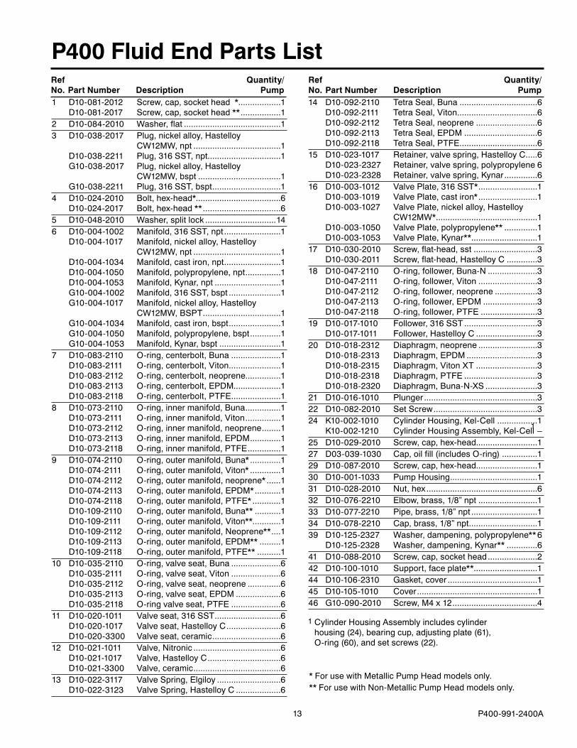
P400 Fluid End Parts List
W0019
Valve Assemblywith Metal Retainer
Non-Metallic Pump Head
with Plastic Retainer
1
P400 with Metallic Pump Head
Cylinder Housing Assembly includes cylinder housing (�4), bearing cup, adjusting plate (61), O-ring (60), and set screws (��).
1
Valve Assembly
P400 with
13 P400-991-�400A
P400 Fluid End Parts List
1 D10-081-�01� Screw, cap, socket head * ..................1 D10-081-�017 Screw, cap, socket head ** .................1� D10-084-�010 Washer, flat .........................................13 D10-038-�017 Plug, nickel alloy, Hastelloy CW1�MW, npt .....................................1 D10-038-��11 Plug, 316 SST, npt...............................1 G10-038-�017 Plug, nickel alloy, Hastelloy CW1�MW, bspt ...................................1 G10-038-��11 Plug, 316 SST, bspt .............................14 D10-0�4-�010 Bolt, hex-head*....................................6 D10-0�4-�017 Bolt, hex-head ** .................................65 D10-048-�010 Washer, split lock ..............................146 D10-004-100� Manifold, 316 SST, npt ........................1 D10-004-1017 Manifold, nickel alloy, Hastelloy CW1�MW, npt .....................................1 D10-004-1034 Manifold, cast iron, npt ........................1 D10-004-1050 Manifold, polypropylene, npt ...............1 D10-004-1053 Manifold, Kynar, npt ............................1 G10-004-100� Manifold, 316 SST, bspt ......................1 G10-004-1017 Manifold, nickel alloy, Hastelloy CW1�MW, BSPT .................................1 G10-004-1034 Manifold, cast iron, bspt ......................1 G10-004-1050 Manifold, polypropylene, bspt .............1 G10-004-1053 Manifold, Kynar, bspt ..........................17 D10-083-�110 O-ring, centerbolt, Buna .....................1 D10-083-�111 O-ring, centerbolt, Viton ......................1 D10-083-�11� O-ring, centerbolt, neoprene...............1 D10-083-�113 O-ring, centerbolt, EPDM....................1 D10-083-�118 O-ring, centerbolt, PTFE .....................18 D10-073-�110 O-ring, inner manifold, Buna ...............1 D10-073-�111 O-ring, inner manifold, Viton ...............1 D10-073-�11� O-ring, inner manifold, neoprene ........1 D10-073-�113 O-ring, inner manifold, EPDM .............1 D10-073-�118 O-ring, inner manifold, PTFE ..............19 D10-074-�110 O-ring, outer manifold, Buna* .............1 D10-074-�111 O-ring, outer manifold, Viton* .............1 D10-074-�11� O-ring, outer manifold, neoprene* ......1 D10-074-�113 O-ring, outer manifold, EPDM* ...........1 D10-074-�118 O-ring, outer manifold, PTFE* ............1 D10-109-�110 O-ring, outer manifold, Buna** ...........1 D10-109-�111 O-ring, outer manifold, Viton** ............1 D10-109-�11� O-ring, outer manifold, Neoprene** ....1 D10-109-�113 O-ring, outer manifold, EPDM** .........1 D10-109-�118 O-ring, outer manifold, PTFE** ..........110 D10-035-�110 O-ring, valve seat, Buna .....................6 D10-035-�111 O-ring, valve seat, Viton .....................6 D10-035-�11� O-ring, valve seat, neoprene ..............6 D10-035-�113 O-ring, valve seat, EPDM ...................6 D10-035-�118 O-ring valve seat, PTFE .....................611 D10-0�0-1011 Valve seat, 316 SST ............................6 D10-0�0-1017 Valve seat, Hastelloy C .......................6 D10-0�0-3300 Valve seat, ceramic .............................61� D10-0�1-1011 Valve, Nitronic .....................................6 D10-0�1-1017 Valve, Hastelloy C ...............................6 D10-0�1-3300 Valve, ceramic .....................................613 D10-0��-3117 Valve Spring, Elgiloy ...........................6 D10-0��-31�3 Valve Spring, Hastelloy C ...................6
14 D10-09�-�110 Tetra Seal, Buna .................................6 D10-09�-�111 Tetra Seal, Viton ..................................6 D10-09�-�11� Tetra Seal, neoprene ..........................6 D10-09�-�113 Tetra Seal, EPDM ...............................6 D10-09�-�118 Tetra Seal, PTFE .................................615 D10-0�3-1017 Retainer, valve spring, Hastelloy C .....6 D10-0�3-�3�7 Retainer, valve spring, polypropylene 6 D10-0�3-�3�8 Retainer, valve spring, Kynar ..............616 D10-003-101� Valve Plate, 316 SST* .........................1 D10-003-1019 Valve Plate, cast iron* .........................1 D10-003-10�7 Valve Plate, nickel alloy, Hastelloy CW1�MW* ...........................................1 D10-003-1050 Valve Plate, polypropylene** ..............1 D10-003-1053 Valve Plate, Kynar** ............................117 D10-030-�010 Screw, flat-head, sst ...........................3 D10-030-�011 Screw, flat-head, Hastelloy C .............318 D10-047-�110 O-ring, follower, Buna-N .....................3 D10-047-�111 O-ring, follower, Viton .........................3 D10-047-�11� O-ring, follower, neoprene ..................3 D10-047-�113 O-ring, follower, EPDM .......................3 D10-047-�118 O-ring, follower, PTFE ........................319 D10-017-1010 Follower, 316 SST ...............................3 D10-017-1011 Follower, Hastelloy C ..........................3�0 D10-018-�31� Diaphragm, neoprene .........................3 D10-018-�313 Diaphragm, EPDM ..............................3 D10-018-�315 Diaphragm, Viton XT ..........................3 D10-018-�318 Diaphragm, PTFE ...............................3 D10-018-�3�0 Diaphragm, Buna-N-XS ......................3�1 D10-016-1010 Plunger ................................................3�� D10-08�-�010 Set Screw ............................................3�4 K10-00�-1010 Cylinder Housing, Kel-Cell .................1 K10-00�-1�10 Cylinder Housing Assembly, Kel-Cell –�5 D10-0�9-�010 Screw, cap, hex-head..........................1�7 D03-039-1030 Cap, oil fill (includes O-ring) ...............1�9 D10-087-�010 Screw, cap, hex-head..........................130 D10-001-1033 Pump Housing .....................................131 D10-0�8-�010 Nut, hex ...............................................63� D10-076-��10 Elbow, brass, 1/8” npt .........................133 D10-077-��10 Pipe, brass, 1/8” npt ............................134 D10-078-��10 Cap, brass, 1/8” npt .............................139 D10-1�5-�3�7 Washer, dampening, polypropylene** 6 D10-1�5-�3�8 Washer, dampening, Kynar** .............641 D10-088-�010 Screw, cap, socket head .....................�4� D10-100-1010 Support, face plate** ...........................144 D10-106-�310 Gasket, cover ......................................145 D10-105-1010 Cover ...................................................146 G10-090-�010 Screw, M4 x 1� ....................................4
* For use with Metallic Pump Head models only.** For use with Non-Metallic Pump Head models only.
1
Cylinder Housing Assembly includes cylinder housing (�4), bearing cup, adjusting plate (61), O-ring (60), and set screws (��).
1
Ref Quantity/ No. Part Number Description Pump
Ref Quantity/ No. Part Number Description Pump

14 P400-991-�400A
24
62
61
64
65
60
50
51
52
53
54
55
56
57
58
63
Qty per piston: 4W0021
66
59
P400 Hydraulic End Parts Lists
Hydraulic End ServiceCAUTION: Do not disassemble or service the hydraulic end.
For assistance, contact Wanner Engineering at (612)332-5681 for the distributor in your area.
1 Piston Assembly includes cylinder, foot, valve plunger, O-rings, spring retainer, and springs (50-59).
50 D10-019-3110 Spring, piston return ............................3
51 K10-04�-1010 Retainer, spring, Kel-Cell ...................3
5� C�3-009-�110 O-ring, valve cylinder, Buna, Kel-Cell ....................................3
53 K10-045-3110 Spring, sleeve valve, Kel-Cell ...........3
54 K10-044-1010 Valve Plunger, Kel-Cell .....................3
55 K10-043-1010 Cylinder, valve, Kel-Cell ...................3
56 D10-034-�110 O-ring, Buna ........................................3
57 D10-041-1010 Washer, ball retainer ...........................3
58 D10-015-3010 Ball ...................................................1�
59 D10-014-1�09 Piston, with foot and retainer ..............3 K10-014-1�10 Piston Assembly, Kel-Cell 1 ...............–
60 D10-075-�110 O-ring, bearing adjusting plate, Buna .1
61 D10-01�-1010 Bearing Adjusting Plate.......................1
6� D10-007-1�10 (X) Cam Assembly ..............................1
63 D10-085-��10 Key, shaft ............................................1
64 D10-031-��10 Seal , Buna ..........................................�
65 D10-037-�110 O-ring, pump housing, Buna ...............1
66 D10-040-�4�1 Nameplate ...........................................1
Ref Quantity/ No. Part Number Description Pump
Ref Quantity/ No. Part Number Description Pump

15 P400-991-�400A
P400 Reducer/Base Parts List
104111
112
112
111
106107
103
105
102
108
109
108
110
109
108
108
110
113
101
100
103
Key is included with P400 Pump Assembly.
W0022
A
A
100 11�-�00 Reducer, 5:1 ratio, 56C ......................1 11�-�01 Reducer, 7.5:1 ratio, 56C ...................1 11�-�0� Reducer, 10:1 ratio, 56C ....................1 11�-�03 Reducer, 15:1 ratio, 56C ....................1 11�-�04 Reducer, �0:1 ratio, 56C ....................1 11�-�05 Reducer, �5:1 ratio, 56C ....................1 11�-�06 Reducer, 30:1 ratio, 56C ....................1 11�-�07 Reducer, 40:1 ratio, 56C ....................1 11�-�08 Reducer, 50:1 ratio, 56C ....................1 11�-�09 Reducer, 60:1 ratio, 56C ....................1 11�-�10 Reducer, 80:1 ratio, 56C ....................1 11�-�11 Reducer, 100:1 ratio, 56C ..................1101 11�-�1� Kit, Protective Cover ...........................110� 11�-�13 Kit, Output Flange, FB ........................1103 11�-��5 Kit, Single Output Shaft, EPM-P300 ..1104 A04-0�4-1�05 Assembly, M�4 Coupling 7/8” x 7/8” ...1105 M10-1�7-10�0 Adapter, P400 ......................................1106 S1031-01� Screw, SHCS, 3/8-16 x 3/4” ................4107 D10-048-�010 Washer, Lock, 3/8” ..............................4108 S1156-100 Washer, 0.31� flat ...............................6109 100-938 Lock Nut, 0.31�-18 ..............................3110 100-948 Screw, HHCS, 5/16-18 x 1” .................3111 D10-087-�010 Screw, HHCS, 3/8-16 x 1-1/8” .............811� D11-048-�011 Washer, 3/8” flat ..................................8113 11�-�17 Metering Pump Base, Carbon Steel, painted.................................................1 11�-�18 Metering Pump Base, 304 SST ..........1
Ref Quantity/ No. Part Number Description Pump

16 P400-991-�400A
P400 TroubleshootingProblem Probable Cause Solution
Motor/Pump Does Not Operate:
No power. Supply correct power according to motor requirements.
Blown fuse/tripped circuit breaker.
Replace/reset, eliminate circuit overload.
Shaft coupling to pump not in place.
Install proper coupling hardware (see parts list).
Current overload - motor. Motor not rated for pump operating conditions - install proper motor.
Thermal overload - motor. Motor not rated for pump and/or ambient operating conditions - supply cooling or install proper motor.
Faulty motor drive/controller. Repair/replace.
Faulty motor. Repair/replace.
Low liquid level in supply tank (if low-level shut-off is used).
Fill tank.
No Delivery
Supply tank empty. Fill tank.
Inlet line or strainer clogged. Clear debris and flush, or replace.
Inadequate supply pressure at pump inlet.
Increase supply pressure by raising fluid level in tank, raising tank, or pressurizing suction tank.
Inlet line too restrictive. Increase inlet line diameter and/or decrease inlet line length.
Fluid viscosity too high. Reduce viscosity if possible (by heat or some other means). Increase inlet line diameter and/or decrease inlet line length. Increase supply pressure.
Vapor lock/cavitation. Increase inlet pressure. Decrease fluid temperature.
Pump valves held open or worn out.
Clear debris and flush, or replace (see Fluid End Service)
System relief valve actuating. Adjust relief valve, or repair, clean, or replace with new relief valve.
Delivery Too Low and/or
Erratic
Review all Probable Causes and Solutions in Problem � No Delivery above.
Air leak(s) in inlet line. Locate all leaks and repair.
System back pressure too low. Adjust back pressure valve to higher setting. Install back pressure valve if none in system.
Pumped fluid characteristics changed.
Monitor supply tank temperature to determine if fluid is too hot (leading to cavitation) or too cold (increasing fluid viscosity). Stabilize temperature at suitable level to resolve problem. Check for entrapped air in the fluid supply system.
Inlet supply pressure changed.
Monitor inlet supply pressure (at the pump) to determine if it is too low, causing a starved condition/cavitation. Stabilize pressure at suitable level to resolve problem.
Pump OK - Calibration system or flow meter error.
Evaluate components and repair/correct problem(s).
Oil condition in pump hydraulic end changed.
Check oil level - if low evaluate for source of leakage. Consult factory for hydraulic end service.
Change oil per recommended guidelines in maintenance section.
Delivery Too High and/or
Erratic.
System back pressure too low. Adjust back pressure valve to higher setting. Install back pressure valve if none in system.
Inlet supply pressure changed.
Monitor inlet supply pressure (at the pump) to determine if it is too high, causing a “flow-through” condition. Stabilize pressure at suitable level to resolve problem.
Pump OK - Calibration system or flow meter error.
Evaluate components and repair/correct problem(s).

17 P400-991-�400A
P400 Replacement Parts Kits
1-2 Pump Configuration P4 For all P400 Pumps
3 Kit Designator K Complete Fluid End Kit* D Diaphragm Kit* V Valve Kit
4-5 Pump Head Version 52 Metallic Pump Head 55 Non-Metallic Pump Head
6 Spring Retainers/Dampening Washers C For Cast Iron pump head M For Kynar® pump head P For Polypropylene pump head S For 316 Stainless Steel pump head T For Hastelloy® C pump head X Not included in Diaphragm Kit
7 Diaphragm & O-ring Material E EPDM G Viton®-XT J PTFE P Neoprene T Buna-N-XS
8-9 Check Valve Material (Valve Spring / Valve & Seat) SS 316 SST / 316 SST TT Hastelloy® C / Hastelloy® C SC 316 SST / Ceramic TC Hastelloy® C / Ceramic XX Not included in Diaphragm Kit
6 95321 84
Kit DesignatorPart Number* Description Qty K D V
D10-018-___ Diaphragm 3 • •
D10-047-___ O-ring, follower 3 • •
D10-074-___ O-ring, outer manifold 1 • • •
D10-073-___ O-ring, inner manifold 1 • • •
D10-083-___ O-ring, center bolt 1 • • •
D10-035-___ O-ring, valve seat 6 • •
D10-0�0-___ Valve seat 6 • •
D10-0�1-___ Valve 6 • •
D10-0��-___ Valve spring 6 • •
D10-0�3-___ Retainer, valve spring 6 • •
A01-113-3400 Threadlocker 1 • •
Hydraulic End Oil (1.5 qt) • •
7
Order Digit Code Description
TO ORDER REPLACEMENT PARTS KIT: A Replacement Parts Kit contains 9 digits corresponding to customer-specified design options.
Metallic Pump Head Kit Contents
* Last four digits of part numbers with –___ refer to specific material of construction.
Kit DesignatorPart Number* Description Qty K D V
D10-018-___ Diaphragm 3 • •
D10-047-___ O-ring, follower 3 • •
D10-109-___ O-ring, outer manifold 1 • • •
D10-073-___ O-ring, inner manifold 1 • • •
D10-083-___ O-ring, center bolt 1 • • •
D10-035-___ O-ring, valve seat 6 • •
D10-0�0-___ Valve seat 6 • •
D10-0�1-___ Valve 6 • •
D10-0��-___ Valve spring 6 • •
D10-09�-___ Tetra seal 6 • •
D10-0�3-___ Retainer, valve spring 6 • •
D10-1�5-___ Washer, dampening 6 • •
A01-113-3400 Threadlocker 1 • •
Hydraulic End Oil (1.5 qt) • •
Non-Metallic Pump Head Kit Contents
* Last four digits of part numbers with –___ refer to specific material of construction.
* Includes Hydraulic End Oil

18 P400-991-�400A
P400 Notes

19 P400-991-�400A
P400 Notes

�0
WANNER ENGINEERING, INC.
1204 Chestnut Avenue, Minneapolis, MN 55403 TEL: (612) 332-5681 FAX: (612) 332-6937 TOLL-FREE FAX [US only]: (800) 332-6812
www.epmpump.com email: [email protected]
Limited WarrantyWanner Engineering, Inc. extends to the original purchaser of equipment manufactured by it and bearing its name, a limited one-year warranty from the date of purchase against defects in material or workmanship, provided that the equipment is installed and operated in accordance with the recommendations and instructions of Wanner Engineering, Inc. Wanner Engineering, Inc. will repair or replace, at its option, defective parts without charge if such parts are returned with transportation charges prepaid to Wanner Engineering, Inc., 1�04 Chestnut Avenue, Minneapolis, Minnesota 55403.
This warranty does not cover:
1. The electric motors (if any), which are covered by the separate warranties of the manufacturers of these components.
�. Normal wear and/or damage caused by or related to abrasion, corrosion, abuse, negligence, accident, faulty installation or tampering in a manner which impairs normal operation.
3. Transportation costs.
This limited warranty is exclusive, and is in lieu of any other warranties (express or implied) including warranty of merchantability or warranty of fitness for a particular purpose and of any non-contractual liabilities including product liabilities based on negligence or strict liability. Every form of liability for direct, special, incidental or consequential damages or loss is expressly excluded and denied.
© �005 Wanner Engineering, Inc. Printed in USAP400-991-�400A 8/�005, Revised 1/�006