+p4t533-c fm(10)dlsvr04.asus.com/pub/asus/mb/sock478/p4t533/t1030_p4t533.pdf · 8 24.5cm (9.6in)...
TRANSCRIPT

®
P4T533

ii
T1030
© 2002

iii

iv
®

v
vi

vii
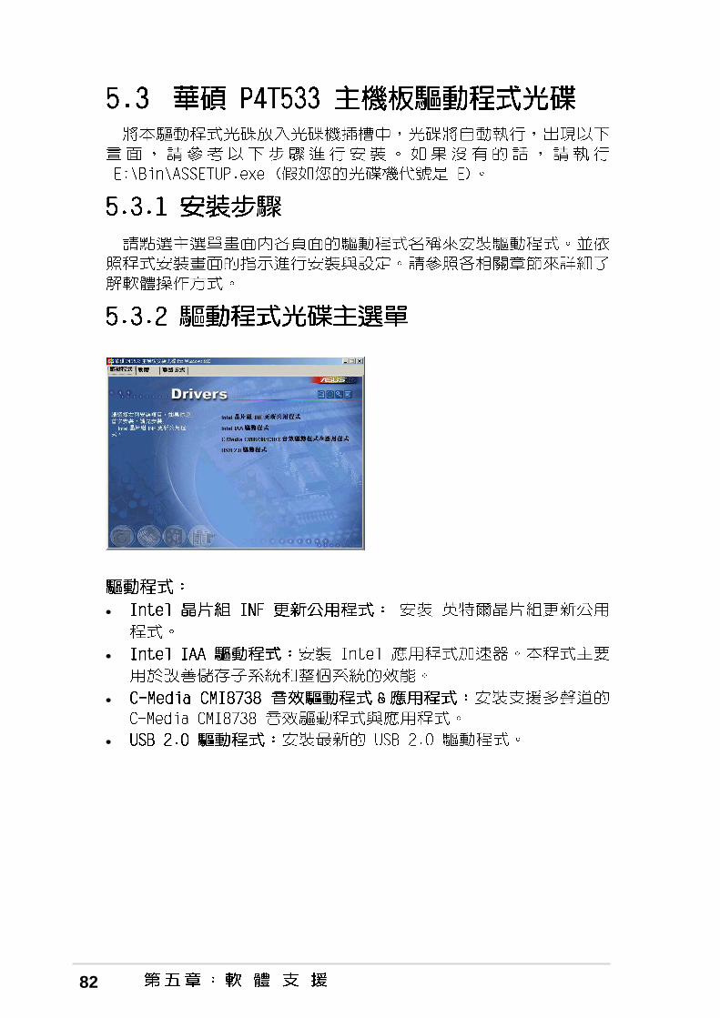
•
•
•
•
•
•
•
•
•
•
•
•

viii
•
•
•
•

ix
™
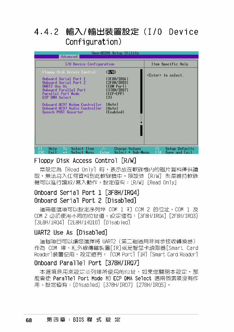
Jumper Free(Default)
2 3
Jumper Mode
1 2

x

xi
® ®

xii


1
®
®

2
®
®
®
®
®

3
4
® ™
®
®

5
2 3 4
22
26
1 5 6
21
10
8
23
14
19
28
7
9
11
13
15
24
32
31
30
16
1817
20
12
25
29
27
33 34
42 41 40 39
36
37
38
35

6
•
•
•
•


7

8
24.5cm (9.6in)
30.5
cm (
12.0
in)
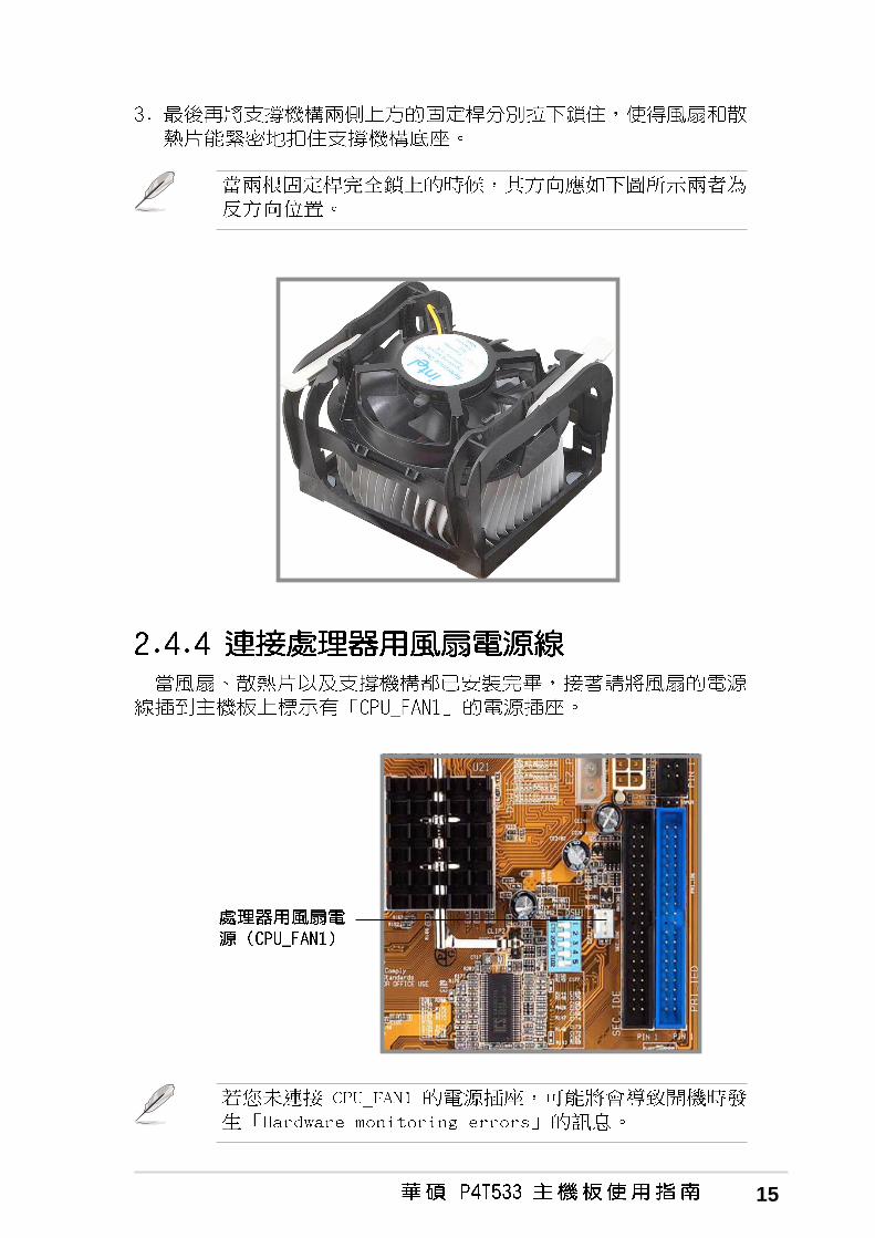
PWRFAN
PANEL
P4T533 CH_FAN
®
CPU_FAN
ATX12V
TRPWR
JEN
Socket 478
LED1
LINE_IN
CD
AU
X
MO
DE
M
AFPANEL
EZ
_PLU
G
USB11_23
SMB
CLCMOS
SPEECH
AA
PA
NE
L
BCS1
HDLED
BCS2
WA
RN
ING
GAME
SMARTCARDUSBPWR23
C-M
edia
CM
I873
8 6C
HA
udio
Con
trol
ler
SPDIF_C
USBPWR01KBPWR
OVER_VOLT
CHASSIS
LO_L
LO_R
USB20_12
USB_EN
USB2.0Controller
SuperI/O
DSWMUL
SMARTSpeech
Controller
PROMISEPDC20276
ATA133Controller
RAID_SWWOR
DSWF
USB1.1T: USB1B: USB2
PS/2KBMST: MouseB: Keyboard
MODESEL
Inte
lLA
NC
ontr
olle
r
USB2.0T: USB1B: USB2

9

10

11
®
®
®
®
®
®
®

12
®
®
®
®
®
®
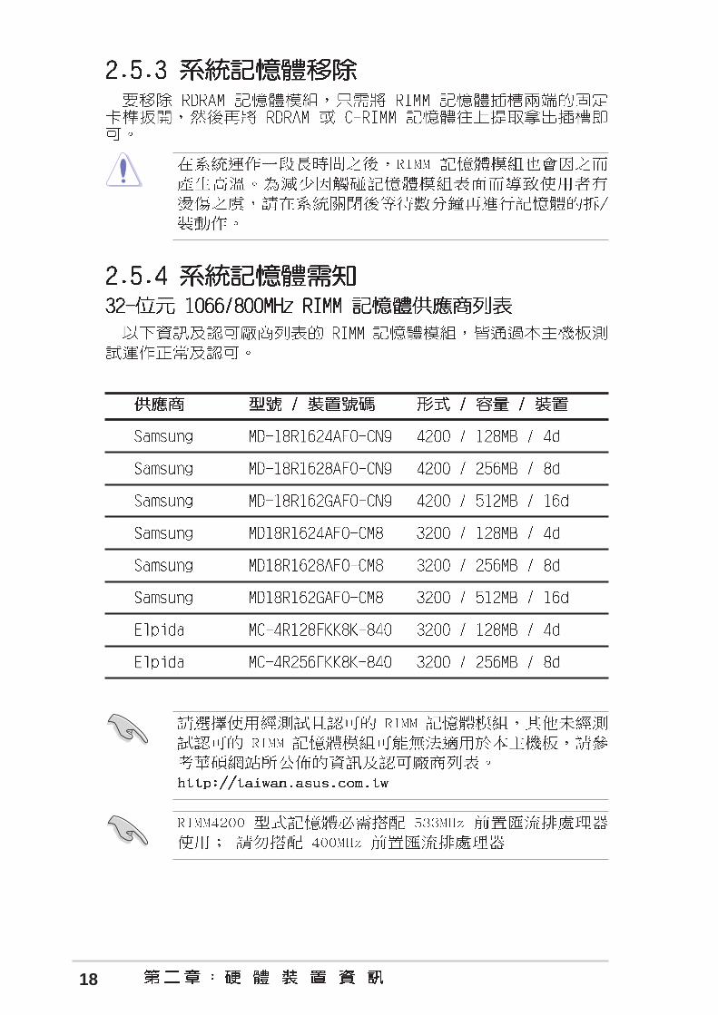
90 - 100

13
®
®
®
®
®

14
15

16

17
P4T533
®
P4T533 184-Pin RIMM Sockets
RIMM Sockets
RIMM with Heat Spreader
C-RIMM
○
○
○
○
○
○
18

19

20
A B C D E F G H

21
P4T533
®
P4T533 Accelerated Graphics Port (AGP)
Keyed for 1.5v

22
P4T533
®
P4T533 JumperFree™ Mode Setting
JEN
Jumper Free(Default)
Jumper Mode
DSW1ON
12
34
5
DSWON
1 2 3 4
2312
P4T533
®
P4T533 DIP Switches
ON
OF
F
DSW
DSW1
ON
OFF
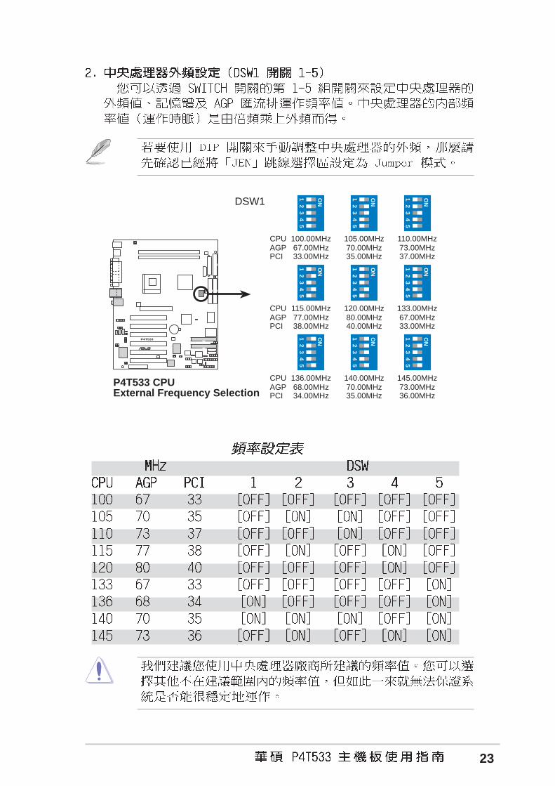
1.Frequency Selection2.Frequency Selection3.Frequency Selection4.Frequency Selection5.Frequency Selection
1.Frequency Multiple2.Frequency Multiple3.Frequency Multiple4.Frequency Multiple
ON
1 2 3 4
ON
12
34
5
23
P4T533
®
DSW1
P4T533 CPUExternal Frequency Selection
CPUAGPPCI
ON
12
34
5
100.00MHz67.00MHz33.00MHz
ON
12
34
5
105.00MHz70.00MHz35.00MHz
ON
12
34
5
110.00MHz73.00MHz37.00MHz
CPUAGPPCI
ON
12
34
5
115.00MHz77.00MHz38.00MHz
ON
12
34
5
120.00MHz80.00MHz40.00MHz
ON
12
34
5
133.00MHz67.00MHz33.00MHz
CPUAGPPCI
ON
12
34
5
136.00MHz68.00MHz34.00MHz
ON
12
34
5
140.00MHz70.00MHz35.00MHz
ON
12
34
5
145.00MHz73.00MHz36.00MHz

24
P4T533
®
ON
1 2 3 4
ON
1 2 3 4
ON
1 2 3 4
ON
1 2 3 4
ON
1 2 3 4
ON
1 2 3 4
ON
1 2 3 4
ON
1 2 3 4
ON
1 2 3 4
ON
1 2 3 4
ON
1 2 3 4
ON
1 2 3 4
ON
1 2 3 4
ON
1 2 3 4
ON
1 2 3 4
ON
1 2 3 4
ON
1 2 3 4
ON
1 2 3 4
ON
1 2 3 4
P4T533 CPU FrequencyMultiple Selection
DSW (P4 533MHZ)
DSW (P4 400MHZ)
12.0x 13.0x 17.0x 18.0x
19.0x 23.0x22.0x21.0x20.0x
16.0x 17.0x 18.0x 19.0x 20.0x
24.0x23.0x22.0x21.0x
16.0x
25
P4T533
®
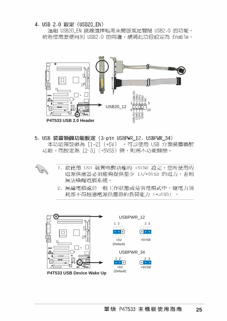
P4T533 USB Device Wake Up
USBPWR_12
USBPWR_34
+5VSB
2 3
+5V
1 2
+5V
1 2
+5VSB
2 3
(Default)
(Default)
P4T533
®
P4T533 USB 2.0 Header
US
B+
5VLD
M1
LDP
1G
ND
NC
US
B+
5VLD
M2
LDP
2G
ND
1 5
6 10USB20_12

26
P4T533
®
P4T533 Bass Center Setting
(BASS/CENTER) (CENTER/BASS)
1 2
BCS1BCS2
2 3
BCS1BCS2
(Default)
P4T533
®
P4T533 Keyboard Power Setting
KBPWR
+5V(Default)
1 2
+5VSB
2 3

27
P4T533
®
OVER_VOLT
P4T533 OVER_VOLT Setting
Over Voltage
2 3
(Default)
1 2
Normal
P4T533
®
P4T533 Speaker Selector
SPEECH
LINEOUTBUZZER(Default)
1 2 2 3

28
P4T533
®
P4T533 Clear RTC RAM
Short jumperto clear CMOS
CLRTC
P4T533
®
P4T533 RAID IDE Setting
RAID_SW
EnableOnboard RAID
Disable
(Default)
1 2 2 3

29
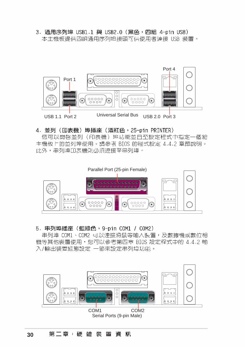
PS/2 Keyboard (6-pin Female)
PS/2 Mouse (6-pin Female)
30
Parallel Port (25-pin Female)
COM1Serial Ports (9-pin Male)
COM2
Universal Serial Bus
Port 1
Port 4
USB 2.0Port 2USB 1.1 Port 3

31
In
Mic
Out
RJ-45

32
P4T533
®
P4T533 IDE Activity LED
TIP: If the case-mounted LED does notlight, try reversing the 2-pin plug.
IDE_LED

33
P4T533
®
P4T533 IDE Connectors
NOTE: Orient the red markings(usually zigzag) on the IDEribbon cable to PIN 1.
PR
I_ID
E
PIN 1
SE
C_ID
E

34
P4T533
®
NOTE: Orient the red markings(usually zigzag) on the IDEribbon cable to PIN 1.
SEC_RAID
PIN 1
PRI_RAID
P4T533 RAID Connectors

35
P4T533
®
NOTE: Orient the red markings onthe floppy ribbon cable to PIN 1.
P4T533 Floppy Disk Drive Connector
PIN 1
FLOPPY
P4T533
®
P4T533 12-Volt Fan Connectors
CPU_FAN
PWRFAN
CH_FAN
GND
Rotation+12V
GN
D
Rot
atio
n+
12V
GN
D
Rot
atio
n+
12V

36
P4T533
®
P4T533 ATX & Auxiliary Power Connectors
ATXPWR
ATX12V
EZ_PLUG
+3.3VDC-12.0VDC
GNDPS_ON#
GNDGND
GND-5.0VDC+5.0VDC+5.0VDC
PWR_OK
+12.0VDC
+3.3VDC+3.3VDCGND
+5.0VDCGND+5.0VDC
GND
+5VSB
+12VGND
NCGND
+12V DC
GND
+12V DC
GND
P4T533
®
P4T533 SMBus Connector
SMB
1
SM
BC
LK
Gro
und
SM
BD
ATA
+3V
FLO
AT
ING

37
P4T533
®
P4T533 USB 1.1 Header
USB11_34
US
B P
ower
US
BP
2–U
SB
P2+
GN
DN
C
US
B P
ower
US
BP
3–U
SB
P3+
GN
D
1 5
6 10
P4T533
®
P4T533 USB 2.0 Header
US
B+
5VLD
M1
LDP
1G
ND
NC
US
B+
5VLD
M2
LDP
2G
ND
1 5
6 10USB20_12

38
P4T533
®
P4T533 Chassis Alarm Lead
CHASSIS
+5V
SB
_MB
Cha
ssis
Sig
nal
GN
D
P4T533
®
P4T533 Internal Audio Connectors
MODEM
Modem-In
GroundModem-Out
Ground
CD(Black)AUX (White)
Right Audio Channel
Left Audio ChannelGroundGround

39
P4T533
®
P4T533 Smartcard
SMARTCARD
NC
SC
RF
ET
#
NC
NC
NC
2
VC
C
GN
DS
CR
UI
SC
RR
ES
#
NC
SC
RC
LK1
NC
SC
RR
ES
T
P4T533
®
P4T533 Internal Line Out Connectors
FP_LO_SWL
FP_LO_SWR
BLO
LF
LOL
BLO
RF
LOR

40
P4T533
®
P4T533 iPanel Connector
+5V
SB
NC
CH
AS
SIS
#
+5
V
PC
IRS
T#
GN
D
CIR
RX
EX
TS
MI#
MLE
D-
NC
BA
TT
NC
SM
BD
ATA
GN
D
+3V
SB
IRR
X
IRT
X
NC
NC
NC
+5V
SM
BC
LK
NC
+5V
SB
NC
+5
VG
ND
CIR
RX
NC
GN
DIR
RX
IRT
X
CIRSIR
IR_CON
AFPANEL1
Connect to iPanel
Connect to AFPANEL Connector

41
P4T533
®
P4T533 LINE_IN Connector
LINE_IN
AG
ND
BLI
NE
_LIN
_LA
LIN
E_L
IN_L
BLI
NE
_IN
_RLI
NE
_IN
_R
P4T533
®
P4T533 Front Panel Audio Connector
AAPANEL
BLINE_OUT_L
MIC2
Line out_R
Line out_L
BLINE_OUT_RNC
MICPWR+5VAAGND
42
P4T533
®
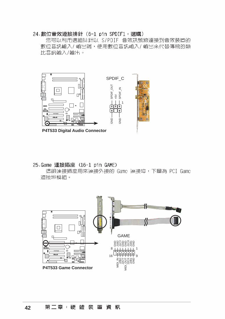
P4T533 Digital Audio Connector
SPDIF_C
GN
D
+5V
SP
DIF
_IN
SP
DIF
_OU
T
GN
D
1
P4T533
®
P4T533 Game Connector
GAME
1
GN
DJ2
B1
J2C
XM
IDI_
OU
TJ2
CY
J2B
2M
IDI_
IN
GN
DJ1
B1
J1C
XG
ND
GN
DJ1
CY
J1B
2G
ND
9
8
16

43
P4T533
®
P4T533 System Panel Connectors* Requires an ATX power supply.
PLE
D
Gro
und
MLE
D
PW
R
+5
V
Key
lock
+5V Spe
aker
SpeakerConnector
Power LED
Gro
und
+5
V
Reset SW
SMI Lead
Message LED
Ext
SM
I#
Gro
und
Res
etG
roun
dG
roun
d
Gro
und
Keyboard Lock
ATX PowerSwitch*
P4T533
®
P4T533 Power Supply Thermal Connector
Ground TRPWR
TRPWR

44


45

46
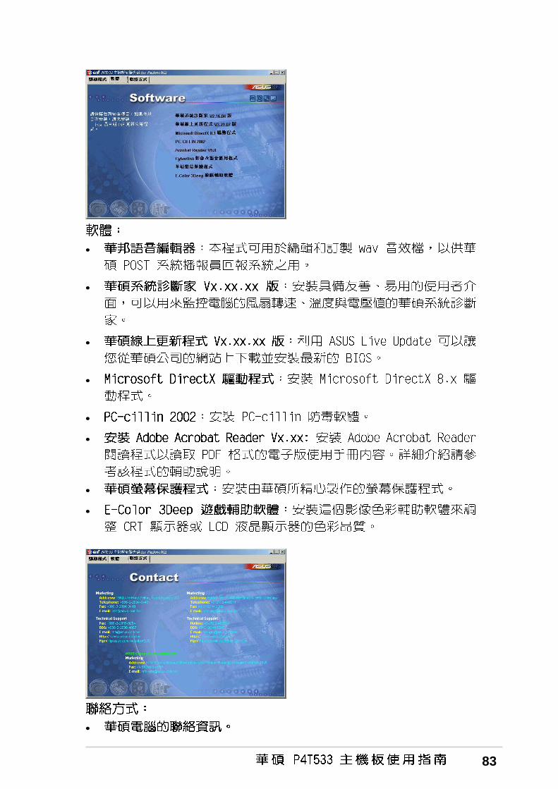
•
•
•
•
•
•
•
•
•
•
•
•
•
•

47
•
•
•
•
•
•
•
•

48


49

50

51

52

53

54

55
<F1> or <Alt + H>
<Esc> or<Alt + X>
← ← ← ← ← or → → → → → (keypad arrow)
↑↑↑↑↑ or ↓ ↓ ↓ ↓ ↓ (keypad arrows)
- (minus key)
+ (plus key) or spacebar
<Enter>
<Home> or <PgUp>
<End> or <PgDn>
<F5>
<F10>

56

57

58

59
60
61

62

63

64
65
Disabled Enabled
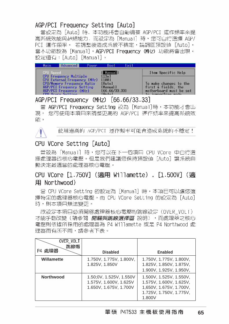
Willamette 1.750V, 1.775V, 1.800V, 1.750V, 1.775V, 1.800V,1.825V, 1.850V 1.825V, 1.850V, 1.875V,
1.900V, 1.925V, 1.950V,
Northwood 1.50;0V, 1.525V, 1.550V 1.500V, 1.525V, 1.550V,1.575V, 1.600V, 1.625V 1.575V, 1.600V, 1.625V,1.650V, 1.675V, 1.700V 1,650V, 1.675V, 1.700V,
1.725V, 1.750V, 1.775V,1.800V

66

67
68
69

70

71

72

73
74

75

76

77

78

79

80


81
82
•
•
•
•
83
•
•
•
•
•
•
•
•
•

84

85

86

87

88

89

90
91
®

92
93

94

95
•
•
•

96

97

98

99
In
Mic
Out

100
®

101
FastBuild (tm) Util ity 1.31 (c) 1996-2000 Promise Technology, Inc.
Auto Setup . . . . . . . . . . [ 1 ]
View Drive Assignments . . . . [ 2 ][ 2 ]
View Array . . . . . . . . . . [ 3 ][ 3 ]
Delete Array . . . . . . . . . [ 4 ][ 4 ]
Rebuild Array. . . . . . . . . [ 5 ][ 5 ]
Controller Configuration . . . [ 6 ][ 6 ]
Press 1..6 to select Option [ESC] Exit
[ Main Menu ]
[ Keys Available ]

102
FastBuild (tm) Util ity 1.31 (c) 1996-2000 Promise Technology, Inc.
[ Keys Available ]
[ Auto Setup Options Menu ]
[ ] Up [ ] Down [ , ,Space] Change Option [ESC] Exit [CTRL-Y] Save[ ] Up [ ] Down [ , ,Space] Change Option [ESC] Exit [CTRL-Y] Save
Mode ........................................
Spare Drive.................................. 0
Drive(s) Used in Array....................... 2
Array Disk Capacity (size in MB)............. 29299
[ Array Setup Configuration ]
Stripe
Optimize Array for: Performance
Typical Application to use: DESKTOP
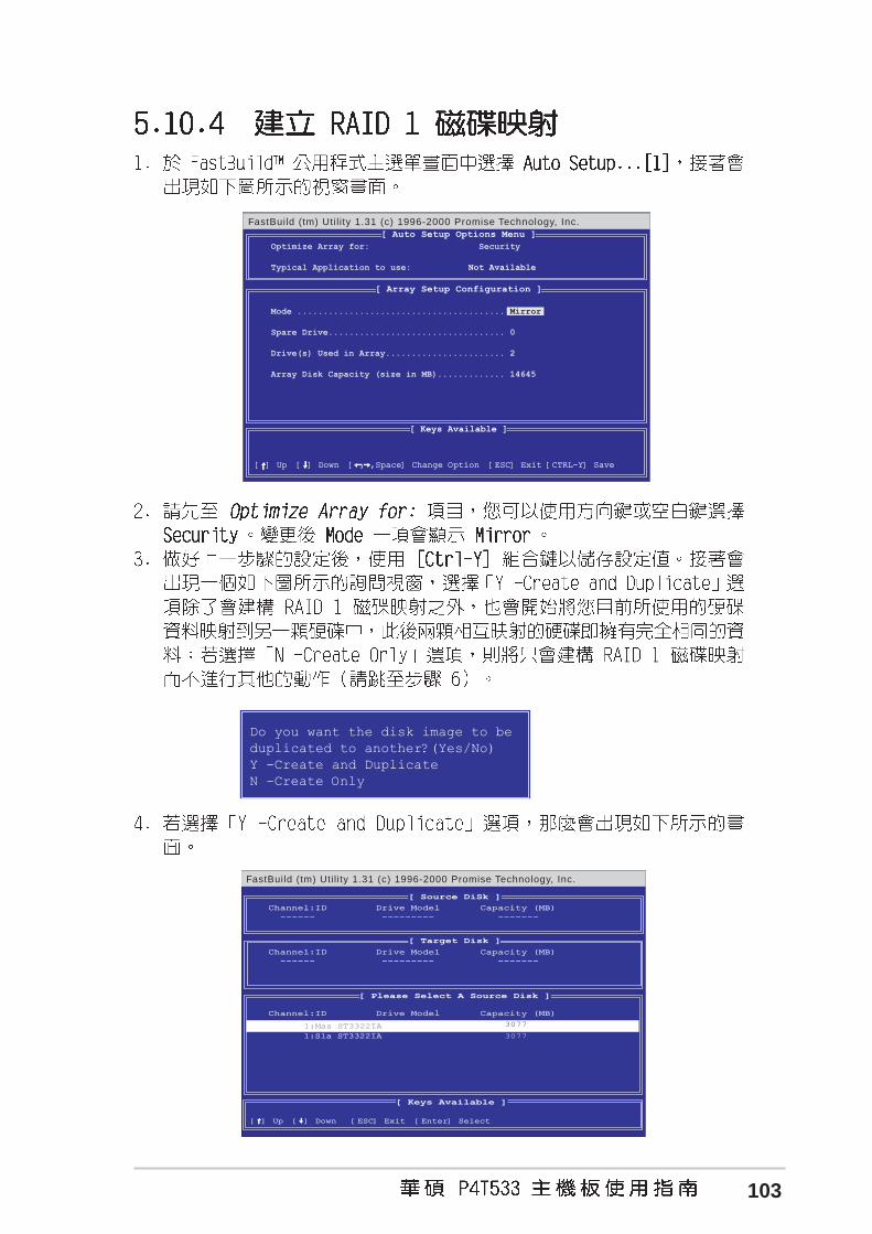
103
FastBuild (tm) Util ity 1.31 (c) 1996-2000 Promise Technology, Inc.
[ Keys Available ]
[ Auto Setup Options Menu ]
Optimize Array for: Security
Typical Application to use: Not Available
[ ] Up [ ] Down [ , ,Space] Change Option [ESC] Exit [CTRL-Y] Save[ ] Up [ ] Down [ , ,Space] Change Option [ESC] Exit [CTRL-Y] Save
Mode ........................................ Mirror
Spare Drive.................................. 0
Drive(s) Used in Array....................... 2
Array Disk Capacity (size in MB)............. 14645
[ Array Setup Configuration ]
FastBuild (tm) Util ity 1.31 (c) 1996-2000 Promise Technology, Inc.
[ Source DiSk ]
[ Please Select A Source Disk ]
[ Keys Available ]
[ ] Up [ ] Down [ESC] Exit [Enter] Select[ ] Up [ ] Down [ESC] Exit [Enter] Select
Channel:IDChannel:ID ------ ------
Drive ModelDrive Model --------- ---------
Capacity (MB)Capacity (MB) ------- -------
[ Target Disk ]
Channel:IDChannel:ID ------ ------
Drive ModelDrive Model --------- ---------
Capacity (MB)Capacity (MB) ------- -------
Channel:IDChannel:ID
1:Sla ST3322IA1:Sla ST3322IA
Drive ModelDrive Model
Capacity (MB)Capacity (MB)
1:Mas ST3322IA 1:Mas ST3322IA 3077
3077
Do you want the disk image to be
duplicated to another?(Yes/No)
Y -Create and Duplicate
N -Create Only

104

105
FastBuild (tm) Util ity 1.31 (c) 1996-2000 Promise Technology, Inc.
[ Keys Available ]
[ ] Up [ ] Down [ESC] Exit [Enter] Select
[ Rebuild Array Menu ]
Array No RAID Mode Total Drv Capacity Status
Array 1 Mirror 2 1628 CriticalArray 2 ----- ----- ----- -----Array 3 ----- ----- ----- -----Array 4 ----- ----- ----- -----
FastBuild (tm) Util ity 1.31 (c) 1996-2000 Promise Technology, Inc.
[ Keys Available ]
[ Select Drive for Rebuild ]
[ ] Up [ ] Down [ESC] Exit [Enter] Select[ ] Up [ ] Down [ESC] Exit [Enter] Select
[ Rebuild Array Menu ]
Array No RAID Mode Total Drv Status
Array 1 Mirror 2 Critical
Stripe Block: Not Available
Channel: ID�� Drive Model��� Capacity (MB)
1: Slave��� ST3322IA���� 3077

106
107
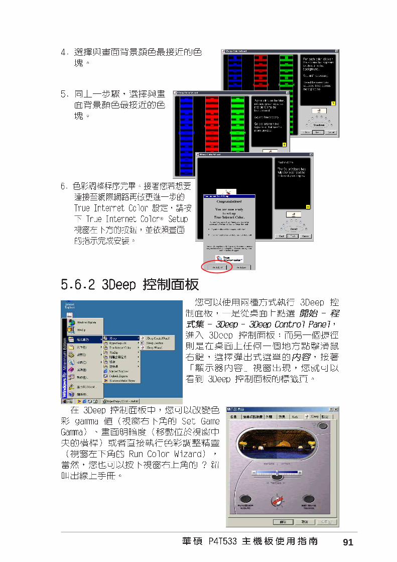
®
®

108