p520-e1-01+nj serial connection guide for e5cc e5ec e5ac digital controller
TRANSCRIPT

7/24/2019 P520-E1-01+NJ Serial Connection Guide for E5CC E5EC E5AC Digital Controller
http://slidepdf.com/reader/full/p520-e1-01nj-serial-connection-guide-for-e5cc-e5ec-e5ac-digital-controller 1/62
Machine Automation Control ler NJ-series
General-purpose Serial
Connection Guide
(RS-485 CompoWay/F) OMRON Corporation
Digital Controller
(E5CC/E5EC/E5AC)
P520-E1-01

7/24/2019 P520-E1-01+NJ Serial Connection Guide for E5CC E5EC E5AC Digital Controller
http://slidepdf.com/reader/full/p520-e1-01nj-serial-connection-guide-for-e5cc-e5ec-e5ac-digital-controller 2/62
About Intellectual Property Right and Trademarks
Microsoft product screen shots reprinted with permission from Microsoft Corporation.
Windows is a registered trademark of Microsoft Corporation in the USA and other countries.
EtherCAT® is registered trademark and patented technology, licensed by Beckhoff Automation GmbH,
Germany.
Company names and product names in this document are the trademarks or registered trademarks of
their respective companies.

7/24/2019 P520-E1-01+NJ Serial Connection Guide for E5CC E5EC E5AC Digital Controller
http://slidepdf.com/reader/full/p520-e1-01nj-serial-connection-guide-for-e5cc-e5ec-e5ac-digital-controller 3/62
Table of Contents
1.
Related Manuals ....................................................................................................... 4
2. Terms and Definition ................................................................................................ 4
3. Remarks ..................................................................................................................... 5
4.
Overview .................................................................................................................... 7
5. Applicable Devices and Support Software........................................................... 7
5.1.
Applicable Devices........................................................................................... 7
5.2. Device Configuration........................................................................................ 9
6. Serial Communications Settings ......................................................................... 10
6.1.
Serial Communications Settings ...................................................................10
6.2. Cable Wiring Diagram.................................................................................... 11
6.3.
Example of Checking Connection.................................................................12
7.
Connection Procedure ..........................................................................................13
7.1. Work Flow.......................................................................................................13
7.2.
Setting Up the Digital Controller..................................................................... 14
7.3. Setting Up the Controller................................................................................18
7.4.
Connection Status Check..............................................................................31
8.
Initialization Method ............................................................................................... 34
8.1. Controller........................................................................................................34
8.2.
Digital Controller............................................................................................. 35
9.
Project file ................................................................................................................36
9.1. Overview.........................................................................................................36
9.2.
Destination Device Command.......................................................................41
9.3. Error Detection Processing............................................................................44
9.4.
Variables.........................................................................................................45
9.5.
Program (ST language).................................................................................47
9.6. Timing Charts .................................................................................................54
9.7. Error Processing ............................................................................................55
10.
Revision History .....................................................................................................60

7/24/2019 P520-E1-01+NJ Serial Connection Guide for E5CC E5EC E5AC Digital Controller
http://slidepdf.com/reader/full/p520-e1-01nj-serial-connection-guide-for-e5cc-e5ec-e5ac-digital-controller 4/62
1. Related Manuals
4
1. Related Manuals
The table below lists the manuals related to this document.
To ensure system safety, make sure to always read and heed the information provided in allSafety Precautions, Precautions for Safe Use, and Precaution for Correct Use of manuals for
each device which is used in the system.
Cat.No Model Manual name
W500 NJ501-[][][][] NJ-series CPU Unit Hardware User's Manual
W501 NJ501-[][][][] NJ-series CPU Unit Software User's Manual
W494 CJ1W-SCU[]2 CJ-series Serial Communications Units Operation Manual
for NJ-series CPU Unit
W502 NJ501-[][][][] NJ-series Instructions Reference ManualW504 SYSMAC-SE2[][][] Sysmac Studio Version 1 Operation Manual
H175 E5CC/E5EC/E5AC Digital Temperature Controllers Communications Manual
H174 E5CC/E5EC/E5AC Digital Temperature Controllers User's Manual
2. Terms and Definition
Terms Explanation and Definition
Serial gateway mode The received message is automatically converted to CompoWay/F,
Modbus-RTU, or Modbus-ASCII by the SCU Unit, depending on the
type of message.

7/24/2019 P520-E1-01+NJ Serial Connection Guide for E5CC E5EC E5AC Digital Controller
http://slidepdf.com/reader/full/p520-e1-01nj-serial-connection-guide-for-e5cc-e5ec-e5ac-digital-controller 5/62
3. Remarks
5
3. Remarks
(1) Understand the specifications of devices which are used in the system. Allow some
margin for ratings and performance. Provide safety measures, such as installing safetycircuit in order to ensure safety and minimize risks for abnormal occurrence.
(2) To ensure system safety, always read and heed the information provided in all Safety
Precautions, Precautions for Safe Use, and Precaution for Correct Use of manuals for
each device used in the system.
(3) The users are encouraged to confirm the standards and regulations that the system must
conform to.
(4) It is prohibited to copy, to reproduce, and to distribute a part of or whole part of this
document without the permission of OMRON Corporation.
(5) This document provides the latest information as of February 2012. The information
contained in this document is subject to change for improvement without notice.

7/24/2019 P520-E1-01+NJ Serial Connection Guide for E5CC E5EC E5AC Digital Controller
http://slidepdf.com/reader/full/p520-e1-01nj-serial-connection-guide-for-e5cc-e5ec-e5ac-digital-controller 6/62
3. Remarks
The following notation is used in this document.
Precautions for Safe Use
Indicates precautions on what to do and what not to do to ensure using the product safely.
Precautions for Correct Use
Indicates precautions on what to do and what not to do to ensure proper operation and
performance.
Addi ti onal Info rmation
Provides useful information.
Additional information to increase understanding or make operation easier.
6
7/24/2019 P520-E1-01+NJ Serial Connection Guide for E5CC E5EC E5AC Digital Controller
http://slidepdf.com/reader/full/p520-e1-01nj-serial-connection-guide-for-e5cc-e5ec-e5ac-digital-controller 7/62
4. Overview
4. Overview
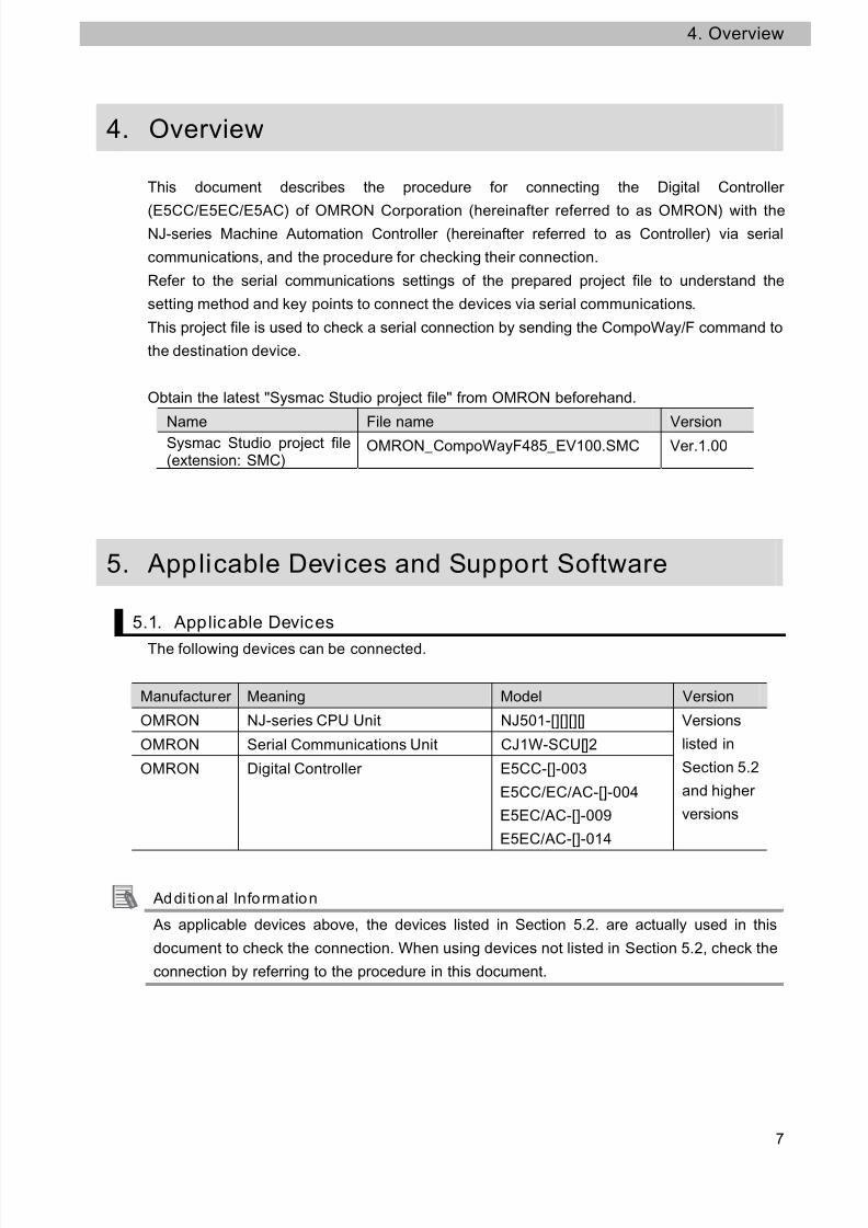
This document describes the procedure for connecting the Digital Controller
(E5CC/E5EC/E5AC) of OMRON Corporation (hereinafter referred to as OMRON) with theNJ-series Machine Automation Controller (hereinafter referred to as Controller) via serial
communications, and the procedure for checking their connection.
Refer to the serial communications settings of the prepared project file to understand the
setting method and key points to connect the devices via serial communications.
This project file is used to check a serial connection by sending the CompoWay/F command to
the destination device.
Obtain the latest "Sysmac Studio project file" from OMRON beforehand.
Name File name Version
Sysmac Studio project file(extension: SMC)
OMRON_CompoWayF485_EV100.SMC Ver.1.00
5. Applicable Devices and Support Software
5.1. Applicable Devices
The following devices can be connected.
Manufacturer Meaning Model Version
OMRON NJ-series CPU Unit NJ501-[][][][]
OMRON Serial Communications Unit CJ1W-SCU[]2
OMRON Digital Controller E5CC-[]-003
E5CC/EC/AC-[]-004
E5EC/AC-[]-009
E5EC/AC-[]-014
Versions
listed in
Section 5.2
and higher
versions
Addi ti onal Info rmation
As applicable devices above, the devices listed in Section 5.2. are actually used in this
document to check the connection. When using devices not listed in Section 5.2, check the
connection by referring to the procedure in this document.
7

7/24/2019 P520-E1-01+NJ Serial Connection Guide for E5CC E5EC E5AC Digital Controller
http://slidepdf.com/reader/full/p520-e1-01nj-serial-connection-guide-for-e5cc-e5ec-e5ac-digital-controller 8/62
5. Appl icable Devices and Support Software
Precautions for Correct Use
You can connect devices with the versions listed in Section 5.2 or higher versions.
For devices whose versions are not listed in Section 5.2, versions are not managed or there
is no version restriction.
To connect a device whose model number is not listed in Section 5.2, use the same version
of the device that is listed.
Addi ti onal Info rmation
This document describes the procedure to establish the network connection. It does not
provide information about operation, installation nor wiring method of each device.
For details on above products (other than communication connection procedures), refer to
the manuals for the corresponding products or contact your OMRON representative.
8

7/24/2019 P520-E1-01+NJ Serial Connection Guide for E5CC E5EC E5AC Digital Controller
http://slidepdf.com/reader/full/p520-e1-01nj-serial-connection-guide-for-e5cc-e5ec-e5ac-digital-controller 9/62
5. Appl icable Devices and Support Software
5.2. Device Configuration
The hardware components to reproduce the connection procedure of this document are as
follows.
Personal computer
(Sysmac Studio installed,OS:Windows7)
NJ501-1500+
CJ1W-SCU42
USB cable
Serial cable(RS-485)
E5CC-RX3A5M-003
Manufacturer Name Model Version
OMRON Serial Communications Unit CJ1W-SCU42 Ver.2.0
OMRON NJ-series CPU Unit NJ501-1500
OMRON Power Supply Unit NJ-PA3001
OMRON Sysmac Studio SYSMAC-SE2[][][] Ver.1.00
OMRON Sysmac Studio project file OMRON_CompoWayF485_EV100.SMC
Ver.1.00
- Personal computer(OS:Windows7)
-
- USB cable(USB 2.0 type B connector)
-
- Serial cable (RS-485) -
OMRON Digital Controller E5CC-RX3A5M-003
Precautions for Correct Use
Obtain the latest Sysmac Studio project file from OMRON in advance.(To obtain the files, contact your OMRON representative.)
Addi ti onal Info rmation
It may not be possible to reproduce the same operation with different devices and versions.Check the configuration, models and versions. If your configuration differs from the ones above,contact your OMRON representative.
Addi ti onal Info rmation
For information on the serial cable (RS-485), refer to 3-3 RS-232C and RS-422A/485 Wiring inthe CJ-series Serial Communications Units Operation Manual for NJ-series CPU Unit (Cat.No.
W494).
Addi ti onal Info rmation
Update the Sysmac Studio to the version specified in this section or higher version using theauto update function. If a version not specified in this section is used, the procedures describedin Section 7 and subsequent sections may not be applicable. In that case, use the equivalentprocedures described in the Sysmac Studio Version 1 Operation Manual (Cat.No. W504).
Addi ti onal Info rmation
In this document, a USB is used to connect with the Controller. For information on how to install
a USB driver, refer to A-1 Driver Installation for Direct USB Cable Connection of the SysmacStudio Version 1 Operation Manual (Cat.No. W504).
9
7/24/2019 P520-E1-01+NJ Serial Connection Guide for E5CC E5EC E5AC Digital Controller
http://slidepdf.com/reader/full/p520-e1-01nj-serial-connection-guide-for-e5cc-e5ec-e5ac-digital-controller 10/62
6. Serial Communications Settings
6. Serial Communications Settings
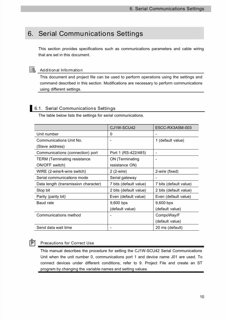
This section provides specifications such as communications parameters and cable wiring
that are set in this document.
Addi ti onal Info rmation
This document and project file can be used to perform operations using the settings and
command described in this section. Modifications are necessary to perform communications
using different settings.
6.1. Serial Communications Settings
The table below lists the settings for serial communications.
CJ1W-SCU42 E5CC-RX3A5M-003
Unit number 0 -
Communications Unit No.
(Slave address)
- 1 (default value)
Communications (connection) port Port 1 (RS-422/485) -
TERM (Terminating resistance
ON/OFF switch)
ON (Terminating
resistance ON)
-
WIRE (2-wire/4-wire switch) 2 (2-wire) 2-wire (fixed)
Serial communications mode Serial gateway -
Data length (transmission character) 7 bits (default value) 7 bits (default value)
Stop bit 2 bits (default value) 2 bits (default value)
Parity (parity bit) Even (default value) Even (default value)
Baud rate 9,600 bps
(default value)
9,600 bps
(default value)
Communications method - CompoWay/F
(default value)
Send data wait time - 20 ms (default)
Precautions for Correct Use
This manual describes the procedure for setting the CJ1W-SCU42 Serial Communications
Unit when the unit number 0, communications port 1 and device name J01 are used. To
connect devices under different conditions, refer to 9. Project File and create an ST
program by changing the variable names and setting values.
10

7/24/2019 P520-E1-01+NJ Serial Connection Guide for E5CC E5EC E5AC Digital Controller
http://slidepdf.com/reader/full/p520-e1-01nj-serial-connection-guide-for-e5cc-e5ec-e5ac-digital-controller 11/62
6. Serial Communications Settings
6.2. Cable Wiring Diagram
For details on the cable wiring, refer to Section 3 Installation and Wiring of the CJ-series Serial
Communications Units Operation Manual for NJ-series CPU Unit (Cat.No. W494).
Check the connector configuration and pin assignment for wiring.
Connector configuration and pin assignment
<E5CC/E5EC/E5AC> Applicable connector: Terminal block
Pin No.Signalname
I/O
1 to 12
13 B(+) I/O
14 A(-) I/O
15-18
<OMRON CJ1W-SCU42> Applicable connector: Terminal block
Cable/Pin arrangement
Serial Communications
Unit (CJ1W-SCU42)
Digital Controller
(E5CC/E5EC/E5AC)
Signal
name
Pin No. Terminal
number
Signal
name
RDA- 1 13 B(+)
11
RDB+ 2 14 A(-)SDA- 3
SDB+ 4
RS-422A
/485
interface
FG 5
RS-485
interface
Terminal block connector Terminal block
Precautions for Correct Use
Turn ON the terminating resistance switch of the Serial Communications Unit, and connect
the terminating resistance of 120Ω (1/2W) to the Digital Controller connected at the end of
the network by referring to the pin arrangement above.

7/24/2019 P520-E1-01+NJ Serial Connection Guide for E5CC E5EC E5AC Digital Controller
http://slidepdf.com/reader/full/p520-e1-01nj-serial-connection-guide-for-e5cc-e5ec-e5ac-digital-controller 12/62
6. Serial Communications Settings
6.3. Example of Checking Connection
This document shows an example of an ST (structured text) program in which the controller
sends/receives CompoWay/F messages to/from Digital Controller.
The Controller and Digital Controller send and receive the "Unit Properties Read" messages.
The following figure shows the outline of the operation.
CPU
Serial
Communications
Unit
Project file
ST Programming
Serial gateway
function
(protocol conversion
function)
Specifying CompoWay/FcommunicationsReading controllerattributes
Sending/receivingCompoWay/F commandReading controller attributes
Variable
Send data
setting area
Receive data
setting arearecvdata
Receive data
Local_
cmddata
Local_
Send data
DriverRS-485
12

7/24/2019 P520-E1-01+NJ Serial Connection Guide for E5CC E5EC E5AC Digital Controller
http://slidepdf.com/reader/full/p520-e1-01nj-serial-connection-guide-for-e5cc-e5ec-e5ac-digital-controller 13/62
7. Connection Procedure
7. Connection Procedure
This section describes how to connect the Controller via serial communications.This document explains the procedures for setting up the Controller and Digital Controller
from the factory default setting. For the initialization, refer to Section 8 Initialization Method.
7.1. Work Flow
Take the following steps to connect the Controller via serial communications.
7.2 Setting Up the Digital Contro ller Set up the Digital Controller.
↓
7.2.1 Parameter Setting Set the parameters of the Digital Controller.
↓
7.3 Setting Up the Contro ller Set up the Controller.
↓ 7.3.1 Setting the Hardware Settings of
the Serial Communications UnitSet the hardware switches on the SerialCommunications Unit and connect to the Controller.
↓
7.3.2 Starting the Sysmac Studio andImporting the Project File
Start the Sysmac Studio Automation Software, andimport the Sysmac Studio project file.
↓
7.3.3 Checking the Parameters andBuilding
Set parameters, check the program of the projectdata and build it.
↓
7.3.4 Connecting Online andTransferring the Project Data
Connect online with the Sysmac Studio and transferthe project data.
↓
7.3.5 Transferring the Unit Settings Transfer the setting data of the SerialCommunication Unit.
↓
7.4 Connection Status Check Execute the project file that was transferred andconfirm that Ethernet communications are normallyperformed.
↓
7.4.1 Executing the Project File andChecking the Receive Data
Execute the project file and check if the correct dataare written to the variables of the Controller.
Precautions for Correct Use
Obtain the latest Sysmac Studio project file from OMRON in advance.(To obtain the files, contact your OMRON representative.)
13

7/24/2019 P520-E1-01+NJ Serial Connection Guide for E5CC E5EC E5AC Digital Controller
http://slidepdf.com/reader/full/p520-e1-01nj-serial-connection-guide-for-e5cc-e5ec-e5ac-digital-controller 14/62
7. Connection Procedure
7.2. Setting Up the Digital Control ler
Set up the Digital Controller.
7.2.1. Parameter Setting
Set the parameters for the Digital Controller.
1Connect the power supply andserial cable to the terminal blockthat is on the back surface ofthe Digital Controller.
*This document describes thecommunications functionsonly. When using the controlfunctions of each device, referto the manuals for each unit.
2Refer to the right figure andcheck the keys, No. 1 and No. 2displays and operationindicators of the DigitalController.
In this document, the followingsymbols are used to indicate thekeys.L: Level keyM: Mode keyU: Up key
D: Down key
Turn ON the power to the DigitalController.
3When the power to the DigitalController is turned ON, theNo.1 display shows the presenttemperature.(Operation level)
Press the L (Level) Key for atleast 3 seconds.
Press the L (Level) Key for atleast 3 seconds.
Serial cable(RS-485)
14

7/24/2019 P520-E1-01+NJ Serial Connection Guide for E5CC E5EC E5AC Digital Controller
http://slidepdf.com/reader/full/p520-e1-01nj-serial-connection-guide-for-e5cc-e5ec-e5ac-digital-controller 15/62
7. Connection Procedure
4The No. 1 display shows
in t
(Initial setting level).
Press theL (Level) Key again.
L (Level) Key
15
5The Communication SettingLevel is entered.The No. 1 display shows
psel
(protocol setting) and the No. 2display shows
cwf
(CompoWay/F).*If the setting values are
different, change theparameters using theU (Up)key andD (Down) key.
Press theM (Mode) Key.
<Setting value>
CWF/Mod
(Default value: CWF)
CWF:CompoWay/FMod:Modbus-RTU
M (Mode) Key
6u no (Communications UnitNo.) is displayed.Check that the communicationsUnit No. is
1
.*If the setting value is different,
change the value using thesame procedure as step 5.
Press the M (Mode) Key.
<Setting value>
0 to 99 (default value: 1)
M (Mode) Key
7bps (Baud rate) is displayed.Check that the communicationsbaud rate is
9.6
kbps.*If the setting value is different,change the value using the
same procedure as step 5.
Press the M (Mode) Key.
<Setting value>
9.6/19.2/38.4/57.6
kbps (default value: 9.6)
M (Mode) Key

7/24/2019 P520-E1-01+NJ Serial Connection Guide for E5CC E5EC E5AC Digital Controller
http://slidepdf.com/reader/full/p520-e1-01nj-serial-connection-guide-for-e5cc-e5ec-e5ac-digital-controller 16/62
7. Connection Procedure
8len
(Communications datalength) is displayed.Check that the communicationsdata length is 7 bits.*If the setting value is different,change the value using thesame procedure as step 5.
Press the M (Mode) Key.
<Setting value>
7/8 bits (default value: 7)
M (Mode) Key
9sbit (Communications stopbits) is displayed.Check that the communicationsstop bits are
2
bits.*If the setting value is different,change the value using thesame procedure as step 5.
Press the M (Mode) Key.
<Setting value>
1/2 bits (default value: 2)
M (Mode) Key
16
10prty
(Communications parity)is displayed.Check that the communicationsparity is
even
.*If the setting value is different,change the value using thesame procedure as step 5.
Press theM (Mode) Key.
<Setting value>
None/Even/Odd
(Default value: Even)
M (Mode) Key
11sdwt (send data wait time) isdisplayed.Check that the send data waittime is .*If the setting value is different,change the value using the
same procedure as step 5.
Press theL (Level) Key.
<Setting value>
0 to 99 ms
(default value: 20)
L (Level) Key

7/24/2019 P520-E1-01+NJ Serial Connection Guide for E5CC E5EC E5AC Digital Controller
http://slidepdf.com/reader/full/p520-e1-01nj-serial-connection-guide-for-e5cc-e5ec-e5ac-digital-controller 17/62
7. Connection Procedure
12in t
(initial setting level) isdisplayed.Press theL (Level) Key for atleast 1 second.
Press theL (Level) Key for atleast 1 second.
13The display is returned to thestatus of step 3 (Operationlevel).
*If you changed the settingvalues, cycle the power supplyso that the settings values takeeffect.
17

7/24/2019 P520-E1-01+NJ Serial Connection Guide for E5CC E5EC E5AC Digital Controller
http://slidepdf.com/reader/full/p520-e1-01nj-serial-connection-guide-for-e5cc-e5ec-e5ac-digital-controller 18/62
7. Connection Procedure
7.3. Setting Up the Controller
Set up the Controller.
7.3.1. Setting the Hardware Settings of the Serial Communications Unit
Set the hardware switches on the Serial Communications Unit.
Precautions for Correct Use
Make sure that the power supply is OFF when you perform the settings.
1Make sure that the powersupply to the Controller is OFFwhen you perform settings.
*If the power supply is turned ON, the following proceduremay not be applicable.
2Connect the serial cable
(RS-485) to Port 1 terminalblock connector.
*This setting is required to usethe Port 1 of SerialCommunications Unit.
3Set the Unit No. Switch to 0.
18
4
Set the terminating resistance
ON/OFF switch for port 1 to ON(terminating resistance ON).
TERMTerminating resistance ON/OFF switchOFF:Terminating resistance OFF[ON]:Terminating resistance ON
5Set the 2-wire/4-wire selectorswitch for port 1 to 2 (2-wire). WIRE:2-wire/4-wire switch
2:2-wire;4:4-wire

7/24/2019 P520-E1-01+NJ Serial Connection Guide for E5CC E5EC E5AC Digital Controller
http://slidepdf.com/reader/full/p520-e1-01nj-serial-connection-guide-for-e5cc-e5ec-e5ac-digital-controller 19/62
7. Connection Procedure
6Connect the SerialCommunications Unit and theEnd Cover to the Controller.Connect the personal computer,Digital Controller and Controllerusing the serial cable and USBcable as shown in 5.2 Device
Configuration.Turn ON the power supply tothe Controller.
Serial cable
CJ1W-SCU42
USB cable
NJ501-1500
19

7/24/2019 P520-E1-01+NJ Serial Connection Guide for E5CC E5EC E5AC Digital Controller
http://slidepdf.com/reader/full/p520-e1-01nj-serial-connection-guide-for-e5cc-e5ec-e5ac-digital-controller 20/62
7. Connection Procedure
7.3.2. Starting the Sysmac Studio and Import ing the Project File
Start the Sysmac Studio Automation Software, and import the Sysmac Studio project file.
Install the software and USB driver beforehand.
1 Start the Sysmac Studio.Click the Import Button.
*If a dialog box is displayed at
start confirming the access
right, select an option to start.
20
2 The Import file Dialog Box is
displayed. Select
OMRON_CompoWayF485_EV
100.SMC (Sysmac Studio
project file) and click the Open
Button.
*Obtain the Sysmac Studioproject file from OMRON.
3 The
OMRON_CompoWayF485_EV
100 project screen is displayed.
The left pane is called Multiview
Explorer, the right pane is called
Toolbox and the middle pane is
called Edit Pane. Edit Pane ToolboxMultiviewExplorer

7/24/2019 P520-E1-01+NJ Serial Connection Guide for E5CC E5EC E5AC Digital Controller
http://slidepdf.com/reader/full/p520-e1-01nj-serial-connection-guide-for-e5cc-e5ec-e5ac-digital-controller 21/62
7. Connection Procedure
7.3.3. Setting the Parameters and Bui lding
Set the parameters, check the program of the project data and build it.
1 Double-click CPU/Expansion
Racks under Configurationsand Setup in the Multiview
Explorer.
2 The CPU/Expansion Racks Tabis displayed on the Edit Pane.
Select the Serial
Communications Unit figure as
shown on the right.
Check that CJ1W-SCU42 is
displayed, the device name is
J01, and the unit number is 0.
*If the setting is different,change the value.
Click Edit Special Unit
Settings.
21
3 The 0 [Unit 0]: Tab is displayed.
Open the pull-down menu of
Parameter group to show and
select Port1: Serial Gateway
Settings.

7/24/2019 P520-E1-01+NJ Serial Connection Guide for E5CC E5EC E5AC Digital Controller
http://slidepdf.com/reader/full/p520-e1-01nj-serial-connection-guide-for-e5cc-e5ec-e5ac-digital-controller 22/62
7. Connection Procedure
4 Parameter group to show is set
to Port1: Serial Gateway
Settings.
The setting items for Port 1:
Serial Gateway Settings are
shown.Check that the Port1: Port
settings are set to User settings
and Port 1: Serial
communications mode is set to
Serial Gateway.
*If the settings are different fromthe above, change the valuesfrom the pull-down menu.
5 Change the other items to the
following settings so that they
are the same as for 6.1.
Data length: 7 bits
Stop bits: 2 bits
Parity: Even
Baud rate: Default value
(9600 bps)
Click the Apply Button after
changing values.
22
6 Double-click I/O Map under
Configurations and Setup on
the Multiview Explorer.
The I/O Map Tab is displayed
and then the parameters for the
unit are listed.
7/24/2019 P520-E1-01+NJ Serial Connection Guide for E5CC E5EC E5AC Digital Controller
http://slidepdf.com/reader/full/p520-e1-01nj-serial-connection-guide-for-e5cc-e5ec-e5ac-digital-controller 23/62
7. Connection Procedure
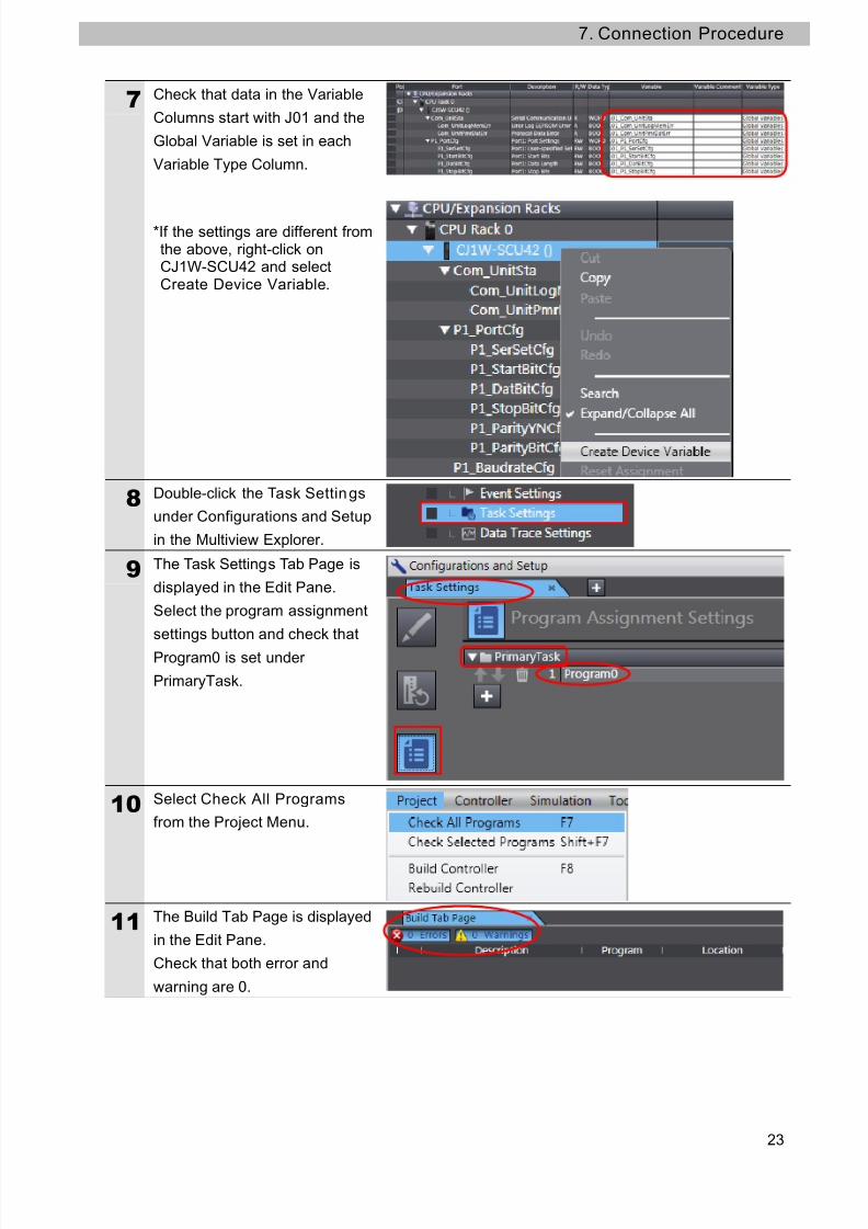
7 Check that data in the Variable
Columns start with J01 and the
Global Variable is set in each
Variable Type Column.
*If the settings are different fromthe above, right-click onCJ1W-SCU42 and selectCreate Device Variable.
8 Double-click the Task Settings
under Configurations and Setup
in the Multiview Explorer.
9 The Task Settings Tab Page is
displayed in the Edit Pane.
Select the program assignment
settings button and check that
Program0 is set under
PrimaryTask.
23
10 Select Check All Programs
from the Project Menu.
11 The Build Tab Page is displayed
in the Edit Pane.
Check that both error and
warning are 0.

7/24/2019 P520-E1-01+NJ Serial Connection Guide for E5CC E5EC E5AC Digital Controller
http://slidepdf.com/reader/full/p520-e1-01nj-serial-connection-guide-for-e5cc-e5ec-e5ac-digital-controller 24/62
7. Connection Procedure
12 Select Rebuild Controller from
the Project Menu.
A screen is displayed indicating
the conversion is being
performed.
24
13 Check that both error andwarning are 0 in the Build Tab
Page.

7/24/2019 P520-E1-01+NJ Serial Connection Guide for E5CC E5EC E5AC Digital Controller
http://slidepdf.com/reader/full/p520-e1-01nj-serial-connection-guide-for-e5cc-e5ec-e5ac-digital-controller 25/62
7. Connection Procedure
7.3.4. Going Online and Transferring the Project Data
Connect online with the Sysmac Studio and transfer the project data.
1 Select Communications Setup
from the Controller Menu.
2 The Communications Setup
Dialog Box is displayed.
Select the Direct connection via
USB Option in the Connection
Type Field.
Click the OK Button.
Addi ti onal Info rmation
For details on the online connections to a Controller, refer to Section 5 Going Online with aController in the Sysmac Studio Version 1.0 Operation Manual (Cat. No. W504).
25

7/24/2019 P520-E1-01+NJ Serial Connection Guide for E5CC E5EC E5AC Digital Controller
http://slidepdf.com/reader/full/p520-e1-01nj-serial-connection-guide-for-e5cc-e5ec-e5ac-digital-controller 26/62
7. Connection Procedure
3 Select Online from the
Controller Menu.
A confirmation dialog is
displayed. Click the Yes Button.
*A displayed dialog depends onthe status of the Controllerused. Select the Yes Button orother button to proceed withthe processing.
*Displayed serial ID differs
depending on the device.
4 When an online connection is
established, a yellow bar isdisplayed on the top of the Edit
Pane.
5 Select Synchronization from
the Controller Menu.
6 The Synchronization Dialog Boxis displayed.
Check that the data to transfer
(NJ501 in the right figure) is
selected. Then, click the
Transfer to Controller Button.
26

7/24/2019 P520-E1-01+NJ Serial Connection Guide for E5CC E5EC E5AC Digital Controller
http://slidepdf.com/reader/full/p520-e1-01nj-serial-connection-guide-for-e5cc-e5ec-e5ac-digital-controller 27/62
7. Connection Procedure
7 A confirmation dialog is
displayed. Click the Yes Button.
A screen stating
"Synchronizing" is displayed.
A confirmation dialog box is
displayed. Click the No Button.
8 Check that the synchronized
data is displayed with the color
specified by “Synchronized” and
that a message is displayed
stating "The synchronization
process successfully finished".
If there is no problem, click the
Close Button.
*If the synchronization fails,
check the wiring and repeat theprocedure described in thissection.
9 Select Reset Controller from
the Controller Menu.
*When Mode is set to RUNMode, Reset Controller cannotbe selected. In this case,select Mode - PROGRAMMode from the Controller
Menu to change to PROGRAMmode and perform theprocedure in this step.
27

7/24/2019 P520-E1-01+NJ Serial Connection Guide for E5CC E5EC E5AC Digital Controller
http://slidepdf.com/reader/full/p520-e1-01nj-serial-connection-guide-for-e5cc-e5ec-e5ac-digital-controller 28/62
7. Connection Procedure
10 A confirmation dialog box is
displayed several times. Click
the Yes Button.
11 The controller is reset, and
Sysmac Studio goes offline.
The yellow bar on the top of the
Edit Pane disappears.Use steps 1 to 4 to go online.
28

7/24/2019 P520-E1-01+NJ Serial Connection Guide for E5CC E5EC E5AC Digital Controller
http://slidepdf.com/reader/full/p520-e1-01nj-serial-connection-guide-for-e5cc-e5ec-e5ac-digital-controller 29/62
7. Connection Procedure
7.3.5. Transferring the Unit Settings
Transfer the setting data of the Serial Communication Unit.
1 Select Mode - PROGRAM
Mode from the Controller Menu.
2 A confirmation dialog box is
displayed. Click the Yes Button.
3 PROGRAM mode is displayed
on the Controller Status Pane.
4 Double-click CPU/Expansion
Racks under Configurations
and Setup in the Multiview
Explorer.
Select the Serial
Communications Unit figure.
Click Edit Special Unit
Settings.
5 The 0 [Unit 0]: Tab is displayed.
Click the Transfer to
Controller Button.
29

7/24/2019 P520-E1-01+NJ Serial Connection Guide for E5CC E5EC E5AC Digital Controller
http://slidepdf.com/reader/full/p520-e1-01nj-serial-connection-guide-for-e5cc-e5ec-e5ac-digital-controller 30/62
7. Connection Procedure
6 A confirmation dialog box is
displayed.
Click the Yes Button.
A dialog box is displayed
indicating transferring is beingperformed.
A confirmation dialog box is
displayed.
Click the Yes Button.
7 The Port Selection Dialog Box is
displayed.
Select Al l ports and click the
OK Button.*You can select HostLink1 instead of All ports.
8 A confirmation dialog box is
displayed.
Click the OK Button.
30

7/24/2019 P520-E1-01+NJ Serial Connection Guide for E5CC E5EC E5AC Digital Controller
http://slidepdf.com/reader/full/p520-e1-01nj-serial-connection-guide-for-e5cc-e5ec-e5ac-digital-controller 31/62
7. Connection Procedure
7.4. Connection Status Check
Execute the project file that was transferred and confirm that serial communications are
performed normally.
Precautions for Correct Use
Please confirm that the serial cable has been connected before proceeding to the following
steps.
If it is not connected, turn OFF the power of the devices, and then connect the serial cable.
7.4.1. Execut ing the Project File and Checking the Receive Data
Execute the project file and check if the correct data are written to the variables of the
Controller.
1
Select Mode - RUN Mode from
the Controller Menu.
A confirmation dialog box is
displayed. Click the Yes Button.
2 RUN mode is displayed on the
Controller Status Pane.
31

7/24/2019 P520-E1-01+NJ Serial Connection Guide for E5CC E5EC E5AC Digital Controller
http://slidepdf.com/reader/full/p520-e1-01nj-serial-connection-guide-for-e5cc-e5ec-e5ac-digital-controller 32/62
7. Connection Procedure
3 Select Watch Tab Page from
the View Menu.
4 The Watch Tab Page isdisplayed in the lower section of
the Edit Pane.
5 Check that the variables shown
on the right are displayed in the
Name Columns.
*If necessary variables are notdisplayed, click Input Name...to add.
*Program0 of the Name isomitted from the followingdescriptions.
6 Click TRUE on the Modify
Column of Input_Start.
The Online value of Input_Start
changes to True.
The program is operated and
CompoWay/F communications
are performed with the
destination device.
Start input
Error codes
Send data
Receive data
Program
execution
status
32

7/24/2019 P520-E1-01+NJ Serial Connection Guide for E5CC E5EC E5AC Digital Controller
http://slidepdf.com/reader/full/p520-e1-01nj-serial-connection-guide-for-e5cc-e5ec-e5ac-digital-controller 33/62
7. Connection Procedure
7 If the communications end
normally, each error code
changes to 0.
*In the case of error end, theerror code for an error is stored.For details on error codes, refer
to 9.7 Error Processing.
The Online value of
Local_Status.Done, which
indicates the program execution
status, changes to True. In the
case of error end,
Local_Status.Error changes to
True.
*When Input_Start changes toFALSE, each Local_Status variable also changes to False.For details, refer to 9.6 TimingCharts.
8 The response data received
from the destination device is
stored in Output_recvCWFdata
(Local_cmdCWFdata is a send
command.)
*The receive data depends onthe Digital Controller used.
*Refer to 9.2.2 DetailedDescription of the Command fordetails of the command.
Receive data
01= Node No.
00=Subaddress
00=End code
0503= Command (MRC,SRC)
0000= Response (MRES,SRES)
E5CC-RX3A5=Receive data (Controller attribute)
00D9=Buffer size
33

7/24/2019 P520-E1-01+NJ Serial Connection Guide for E5CC E5EC E5AC Digital Controller
http://slidepdf.com/reader/full/p520-e1-01nj-serial-connection-guide-for-e5cc-e5ec-e5ac-digital-controller 34/62
8. Initialization Method
8. Initialization Method
This document explains the setting procedure from the factory default setting.
If the device settings have been changed from the factory default setting, some settings maynot be applicable as described in this procedure.
8.1. Controller
To initialize the Controller, it is necessary to initialize the CPU Unit and Serial Communications
Unit.
8.1.1. CPU Unit
To initialize the settings of the Controller, select Clear All Memory from the ControllerMenu of the Sysmac Studio.
34

7/24/2019 P520-E1-01+NJ Serial Connection Guide for E5CC E5EC E5AC Digital Controller
http://slidepdf.com/reader/full/p520-e1-01nj-serial-connection-guide-for-e5cc-e5ec-e5ac-digital-controller 35/62
8. Initialization Method
8.1.2. Serial Communications Unit
To initialize the settings of the Serial Communications Unit, select Edit Special Unit
Settings of CJ1W-SCU42 in CPU/Expansion Racks from the Sysmac Studio.
Click the Return to default Button and click the Apply Button. Then, click the Transfer to
Controller Button.
8.2. Digital Controller
For information on how to initialize the Digital Controller, refer to Parameter Initialization of 6-8
Advanced Function Setting Level in the Digital Temperature Controllers User's Manual
(Cat.No. H175).
35

7/24/2019 P520-E1-01+NJ Serial Connection Guide for E5CC E5EC E5AC Digital Controller
http://slidepdf.com/reader/full/p520-e1-01nj-serial-connection-guide-for-e5cc-e5ec-e5ac-digital-controller 36/62
9. Project fi le
9. Project fi le
This section describes the details of the project file used in this document.
9.1. Overview
This section explains the specifications and functions of the project file used to connect the
Digital Controller (E5CC/E5EC/E5AC) (hereinafter referred to as a destination device) to the
Controller (Serial Communications Unit) (hereinafter referred to as an SCU Unit).
The project file is a Sysmac Studio project file.
The following data has already been set in this project file.
•SCU Unit communications settings and program task settings•A program and function block to perform CompoWay/F communications
•Variable tables and data type definitions of the variables used in ST programs
This project file uses CompoWay/F communications (serial gateway function) of the SCU Unit
to read the controller attributes of the destination device and to detect whether the operation
ends normally or abnormally.
The normal end of this project file indicates the normal end of the CompoWay/F
communications.
The error end indicates the error end of the CompoWay/F communications and destination
device error (judged on the response data from the destination device).
Addi ti onal Info rmation
OMRON has confirmed that normal communications can be performed using this project fileunder the OMRON evaluation conditions including the test system configuration, version ofeach product, and product Lot, No. of each device which was used for evaluation.OMRON does not guarantee the normal operation under the disturbance such as electricalnoise and the performance variation of the device.
Addi ti onal Info rmation
With Sysmac Studio, a data type + "#" are prefixed to decimal data and a data type + "#" +
"16" + "#" are prefixed to hexadecimal data when it is necessary to distinguish between
decimal and hexadecimal data. (e.g., INT#1000 decimal -> INT#16#03E8 hexadecimal. For
DINT, a data type + "#" are unnecessary.)
36

7/24/2019 P520-E1-01+NJ Serial Connection Guide for E5CC E5EC E5AC Digital Controller
http://slidepdf.com/reader/full/p520-e1-01nj-serial-connection-guide-for-e5cc-e5ec-e5ac-digital-controller 37/62
9. Project fi le
9.1.1. Communications Data Flow
The following shows the data flow from issuing a CompoWay/F command from the
Controller (SCU Unit) to the destination device to receiving the response data from the
destination device.
1. Sending a command The send message set with the ST program is sent
from the SCU Unit to the destination device.
↓
2. Receiving a response The response data, which was received by the SCU
Unit from the destination device, is stored in the
specified internal variable of the CPU Unit.
9.1.2. SendCmd Instruct ion and Send/Receive MessageThis section outlines the send command instruction (SendCmd, hereinafter referred to as
"SendCmd instruction") and send/receive process of message.
Addi ti onal Info rmation
For details, refer to 2 Instruction Descriptions - Communications Instructions in the
NJ-series Instructions Reference Manual (Cat. No. W502).
SendCmd instruction argument data
37

7/24/2019 P520-E1-01+NJ Serial Connection Guide for E5CC E5EC E5AC Digital Controller
http://slidepdf.com/reader/full/p520-e1-01nj-serial-connection-guide-for-e5cc-e5ec-e5ac-digital-controller 38/62
9. Project fi le
38
[CmdDat[]array: Command array (Send data)]
The command (send data) is converted from the Local_cmdCWFdata string variable to
Local_cmddata BYTE array variable before setting.
Variable of BYTE array: Local_cmddata,SendCmd_instance.CmdDat
[0] [1] [2] [3] [4] [5] [6] [7] [8] [9] [10] ・・
28 03 AA BB CC DD EE FF GG HH II **
C o m m a n d
CompoWay/Fcommunications
command
Nodenumber
Subaddress SID CommandMRC SRC
Text
*#16#2803 CompoWay/F communications command is a serial gateway function
of the SCU Unit and is a command used for the CompoWay/F.
*The command data after AA in the shaded areas are expressed in ASCII.
[RespDat[]array: Response storage array (receive data)]
The response (receive data) is received in a BYTE array. After receiving, the BYTE array
(Local_recvdata) is converted into a character string variable (Output_recvCWFdata) and
checked.
BYTE array variable: Local_recvdata,SendCmd_instance.RespDat
[0] [1] [2] [3] [4] [5] [6] [7] [8] [9] [10] [11] [12] [13] [14] [15] [16] [17] ・・
28 03 aa bb AA BB CC DD cc dd FF GG HH II ee ff gg hh **
Command Response
R e s p o n s e
CompoWay/Fcomm.
command
Comma-nd endcode
Nodenumber
Subaddress
End codeMRC SRC MRES SRES
Text
*The response data after AA in the shaded areas are expressed in ASCII.
*Response data not in thick frames such as AA will be the same as those of the
command code.
*Response data in thick frames will be stored in the variables below as the
destination device error code when a destination device error occurs. "aa" and
"bb" command end codes are not used in this document or this project file. For
details on error codes, refer to 9.7.2 Destination Device Errors.
Ouitput_CWFErrCode1: End code
Ouitput_CWFErrCode2: Response (MRES,SRES)

7/24/2019 P520-E1-01+NJ Serial Connection Guide for E5CC E5EC E5AC Digital Controller
http://slidepdf.com/reader/full/p520-e1-01nj-serial-connection-guide-for-e5cc-e5ec-e5ac-digital-controller 39/62
9. Project fi le
39
[DstNetAdr: Destination network address]
The following table shows variables that store a destination network address.
Variable Items Datatype
Description Setvalue
Default
DstNetAdr Destinationnetwork address
_sDNET _ADR
Destination network address
NetNo Networkaddress
USINT USINT#16#00 (fixed): Localnetwork
USINT#16#00
USINT#16#00
NodeNo Node address USINT USINT#16#00 (fixed):Communications in the localcontroller
USINT#16#00
USINT#16#00
UnitNo Unit address BYTE Configure the settings as follows.Unit address of serial portFor Serial Communication Unit
Port 1: #16#80 + #16#04 x [Unitnumber (Hexadecimal)]Port 2: #16#81 + #16#04 x [Unitnumber (Hexadecimal)]
(Example of unit number (No.10)port 2: serial port unit address=
#16#81+#16#04x#16#0A=#16#81+#16#28= #16#A9)
BYTE#16#80
BYTE#16#00
[CommPort: Destination serial port]
The following table shows a variable that stores a destination serial port number.
Variable Items Data type Description Setvalue
Default
CommPort Destinationserial port
_ePORT _NONE: The destination is not aserial port in Host Link Mode.*To specify the serial port unitaddress as the Destination unitaddress, set _NONE.
_NONE _NONE
[CmdSize: Command data size]
The following table shows the variable that stores the number of bytes of the command
(send data).
Variable Items Data type Description Setvalue
Default
CmdSize Command datasize
UINT Sets the number of command databytes. (#0002 to maximum datalength)
UINT#11 UINT#0
[Option: Response]
The following table shows the variables that store settings to receive a response.
Variable Items Data type Description Setvalue
Default
Option Response _sRESPONSE
Response monitoring and retryspecifications
isNonResp No response BOOL TRUE: Response is not requiredFALSE: Response is required
FALSE FALSE
TimeOut Timeout time UINT Sets UINT#1 to 65535 (indicates0.1 to 6553.5 seconds). (UINT#0:2 seconds (Default))
#0 UINT#0
Retry No. of resends USINT Sets USINT#0 to #15 (0 to 15times).
#3 USINT#0

7/24/2019 P520-E1-01+NJ Serial Connection Guide for E5CC E5EC E5AC Digital Controller
http://slidepdf.com/reader/full/p520-e1-01nj-serial-connection-guide-for-e5cc-e5ec-e5ac-digital-controller 40/62
9. Project fi le
Send/receive message
[Overview of send/receive message]
Send message (Command)
Des
40
[Relation between send command (SendCmd instruction operand) and send message]
Local_cmdCWFdata
Node No. Subaddress SIDCommand
MRC SRCText
[0] [1] [2] [3] [4] [5] [6] [7] [8] [9] [10] ・・Local_cmddata 28 03 AA BB CC DD EE FF GG HH II **
CPU→SCU
CompoWay/Fcomm.
command
Node No. Subaddress SID CommandMRC SRC
Text
STX Command ETXSCU→ Destinationdevice(Senddata)
16#02
NodeNo.
Subaddress
SIDMRC SRC
Text16#03
BCC
[Relation between receive response (SendCmd instruction operand) and receive message]
STX Command Response ETXDestination
device →
SCU(Receivedata)
16#02
NodeNo.
Subaddress
Endcode MRC SRC MRES SRES
Text16#03
BCC
[0] [1] [2] [3] [4] [5] [6] [7] [8] [9] [10] [11] [12] [13] [14] [15] [16] [17] ・Local
_recvdata
28 03 aa bb AA BB CC DD cc dd FF GG HH II ee ff gg hh **
Command ResponseSCU→
CPU
CompoWay/Fcomm.
command
Commandendcode
NodeNo.
Subaddress
End codeMRC SRC MRES SRES
Text
Command ResponseOutput_recvCWFdata
NodeNo.
Subaddr ess
Endcode MRC SRC MRES SRES
Text
Controller
tination
device
STX コマンド ETX
16#02
ノード
No.
サブア
ドレスSID
MRC SRC
Command テキス
ト 16#03
BCCNode
No.
TextSub
address
STX コマンド レスポンス ETX
16#02
ノード
No.
サブアド
レス
終了コー
ド MRC SRC MRES SRES
テキ
スト 16#03
BCC
Response Text
Receive message (Response)
Subaddress
NodeNo.
Endcode
Command

7/24/2019 P520-E1-01+NJ Serial Connection Guide for E5CC E5EC E5AC Digital Controller
http://slidepdf.com/reader/full/p520-e1-01nj-serial-connection-guide-for-e5cc-e5ec-e5ac-digital-controller 41/62
9. Project fi le
41
9.2. Destination Device Command
This section explains the destination device command used in this project file.
9.2.1. Overview of the Command
This project file uses the Read Controller Attributes command to read information from thedestination device.
Command name Description
Read Controller Attributes Reads the attributes of the destination device.
9.2.2. Detailed Descr ipt ion of the Command
This section explains the Read Controller Attributes command.
Send message command format
This is the command format of the message that is sent by the Controller to the destinationdevice according to the setting of the Read Controller Attributes command.
•Except for STX, ETX and BCC, data are sent in ASCII.
•STX, ETX and BCC are automatically added to the send message by the SCU Unit.
•Data not used are moved forward.
DataNo ofbytes
Remarks
Variable name andsetting value of theCWFCmdsSetinstruction
Data type
STX 1 Fixed (#16#02)
Node number 2 Sets the communications
unit No. of the destinationdevice.
NodeNo "01" STRING[3]
Subaddress 2 Not used (Fixed value) SubAddress "00" STRING[3]
SID 1 Not used (Fixed value) SID "0" STRING[2]
Command(MRC+SRC)
4 Sets the Read Controller Attributes command code.
MRCSRC "0503" STRING[5]
Text * Not used for the ReadController Attributescommand.
SendText "" STRING[128]
ETX 1 Fixed (#16#03)
BCC 1 BCC
•Data are set and joined in CWFCmdsSet_instance.
VariableDescription(data type)
Data Description
Local_cmdCWFdata
Send message(STRING[256])
CONCAT(NodeNo, SubAddress,SID, MRCSRC,SendText)
After converting from a stringvariable to a BYTE arrayvariable, this variable is usedas send data of the SendCmdinstruction(SendCmd_instance).

7/24/2019 P520-E1-01+NJ Serial Connection Guide for E5CC E5EC E5AC Digital Controller
http://slidepdf.com/reader/full/p520-e1-01nj-serial-connection-guide-for-e5cc-e5ec-e5ac-digital-controller 42/62
9. Project fi le
42
Response format of the receive message
This is the response format of the normal message received by the Controller from the
destination device according to the settings of the Read Controller Attributes command.
•Except for STX, ETX and BCC, data are received in ASCII.
•STX, ETX and BCC are automatically removed from the receive message by the SCUUnit.
•Data not used are moved forward.
DataNumberof bytes
Receivedata
Remarks
STX 1 Fixed (#16#02)
Node number 2 "01" Same as command data
Subaddress 2 "00" Same as command data
End code 2 "00" Normal end
Command(MRC+SRC)
4 "0503" Same as command data
Response(MRES+SRES) 4 "0000" Normal end
Text * The data corresponding to the command is stored.For Read Controller Attributes command, the followingdata are stored.
Model 10 ** Reads the model of the destination device.
BufferSize 4 ** Reads the communication buffer size.
ETX 1 Fixed (#16#03)
BCC 1 BCC
Response format of the receive message (error)
The response format for an error message received by the Controller from the destination
device.
•Except for STX, ETX and BCC, data are received in ASCII.
•STX, ETX and BCC are automatically removed from the receive message by the SCU
Unit.
DataNumberof bytes
Receivedata
Remarks
STX 1 Fixed (#16#02)
Node number 2 "01" Same as command data
Subaddress 2 "00" Same as command data
End code 2 "XX" End code
For details on error codes, refer to 9.7.2Destination Device Error .
Command(MRC+SRC)
4 "0503" Same as command data
Response(MRES+SRES)
4 "yyyy" Response codesFor details on error codes, refer to 9.7.2Destination Device Error .
ETX 1 Fixed (#16#03)
BCC 1 BCC

7/24/2019 P520-E1-01+NJ Serial Connection Guide for E5CC E5EC E5AC Digital Controller
http://slidepdf.com/reader/full/p520-e1-01nj-serial-connection-guide-for-e5cc-e5ec-e5ac-digital-controller 43/62
9. Project fi le
Addi ti onal Info rmation
To use a destination device command other than the command used in this document, you
may need to set up the destination device according to the command used. For details on
the destination device command and send/receive messages, refer to Chapter 2
CompoWay/F Communications Procedures and Chapter 3 Communications Data for
CompoWay/F in the Digital Temperature Controllers Communications Manual (Cat. No.
H175).
43

7/24/2019 P520-E1-01+NJ Serial Connection Guide for E5CC E5EC E5AC Digital Controller
http://slidepdf.com/reader/full/p520-e1-01nj-serial-connection-guide-for-e5cc-e5ec-e5ac-digital-controller 44/62
9. Project fi le
9.3. Error Detection Processing
This section explains the error detection processing of this project file.
9.3.1. Error Detection in the Project File
This project file detects and handles errors of the following items (1) to (2). For error codes,refer to 9.7 Error Processing.
(1)Errors at execution of SendCmd instruction (SendCmd instruction error)The errors in the Unit, command format, or parameters at the execution of the SendCmd
instruction are detected as "SendCmd instruction errors". An error is detected according to
the error codes ErrorID and ErrorIDEx of the SendCmd instruction.
If a communications error is caused by a transmission error due to, for example, a
character corruption or unmatched baud rate setting, the transmission error status
(J01_P1_TransErrSta) allocated variable area of the SCU is stored in the output variable to
show the communication error status.
(2)Errors in the destination device (Destination device error)
Errors that occur in the destination device are detected as the destination device errors
such as a command error, parameter error and an error that prevents execution. An error is
detected according to the response data which is sent from the destination device. When
an error occurred in the destination device, the error codes are set in the end code and
response of the receive data.
Serial cable
Controller Destination device
(1) (2)
[0] [1] [2] [3] [4] [5] [6] [7] [8] [9] [10] [11] [12] [13] [14] [15] [16] [17] ・
28
44
03 aa bb AA BB CC DD cc dd FF GG HH II ee ff gg hh **
Local _recvdata CompoWay/F
comm.
command
Command end code
Nodenumber
Subaddress
End code Command Response Text
7/24/2019 P520-E1-01+NJ Serial Connection Guide for E5CC E5EC E5AC Digital Controller
http://slidepdf.com/reader/full/p520-e1-01nj-serial-connection-guide-for-e5cc-e5ec-e5ac-digital-controller 45/62
9. Project fi le
45
9.4. Variables
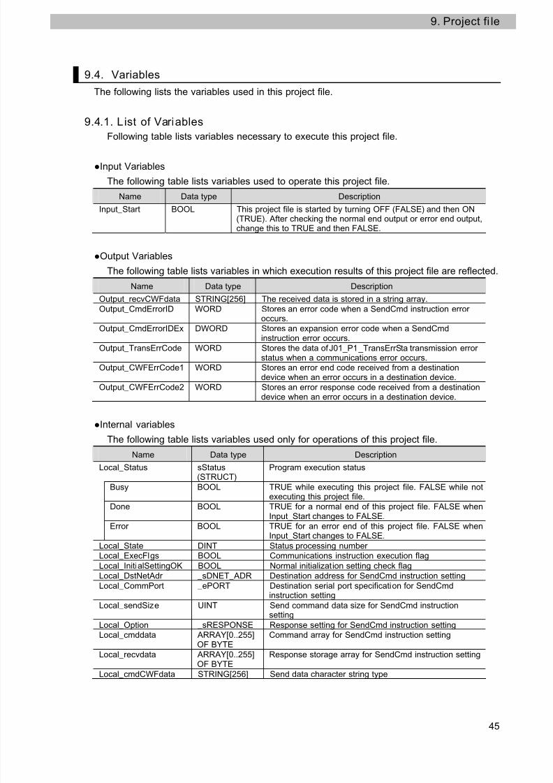
The following lists the variables used in this project file.
9.4.1. L ist of Variables
Following table lists variables necessary to execute this project file.
Input Variables
The following table lists variables used to operate this project file.
Name Data type Description
Input_Start BOOL This project file is started by turning OFF (FALSE) and then ON(TRUE). After checking the normal end output or error end output,change this to TRUE and then FALSE.
Output Variables
The following table lists variables in which execution results of this project file are reflected.Name Data type Description
Output_recvCWFdata STRING[256] The received data is stored in a string array.
Output_CmdErrorID WORD Stores an error code when a SendCmd instruction erroroccurs.
Output_CmdErrorIDEx DWORD Stores an expansion error code when a SendCmdinstruction error occurs.
Output_TransErrCode WORD Stores the data of J01_P1_TransErrSta transmission errorstatus when a communications error occurs.
Output_CWFErrCode1 WORD Stores an error end code received from a destinationdevice when an error occurs in a destination device.
Output_CWFErrCode2 WORD Stores an error response code received from a destinationdevice when an error occurs in a destination device.
Internal variables
The following table lists variables used only for operations of this project file.
Name Data type Description
Local_Status sStatus(STRUCT)
Program execution status
Busy BOOL TRUE while executing this project file. FALSE while notexecuting this project file.
Done BOOL TRUE for a normal end of this project file. FALSE whenInput_Start changes to FALSE.
Error BOOL TRUE for an error end of this project file. FALSE whenInput_Start changes to FALSE.
Local_State DINT Status processing numberLocal_ExecFlgs BOOL Communications instruction execution flag
Local_InitialSettingOK BOOL Normal initialization setting check flag
Local_DstNetAdr _sDNET_ADR Destination address for SendCmd instruction setting
Local_CommPort _ePORT Destination serial port specification for SendCmdinstruction setting
Local_sendSize UINT Send command data size for SendCmd instructionsetting
Local_Option _sRESPONSE Response setting for SendCmd instruction settingLocal_cmddata ARRAY[0..255]
OF BYTECommand array for SendCmd instruction setting
Local_recvdata ARRAY[0..255]OF BYTE
Response storage array for SendCmd instruction setting
Local_cmdCWFdata STRING[256] Send data character string type

7/24/2019 P520-E1-01+NJ Serial Connection Guide for E5CC E5EC E5AC Digital Controller
http://slidepdf.com/reader/full/p520-e1-01nj-serial-connection-guide-for-e5cc-e5ec-e5ac-digital-controller 46/62
9. Project fi le
9.4.2. List of Variables Used in Function Block/Function
The following tables list the user-defined function block used in the program to execute this
project file.
For variables used for the function block, refer to 9.5.3 Detailed Description of Function
Block.Name Data type Description
CWFCmdsSet_instance CWFCmdsSet Sets a byte size of the send/receive data and a send
message.
9.4.3. L ist of System Variables
The following table lists variables necessary to execute this project file.
The following allocations are determined according to the unit number that is set for the
Serial Communications Unit and cannot be changed.
Allocated variables
Name Data type Description
J01_P1_TransErr BOOL Transmission error flag (Unit 0, Port 1)
J01_P1_TransErrSta WORD Transmission error status (Unit 0, Port 1)
Addi ti onal Info rmation
For information on variables of the Serial Communications Unit, refer to 5-2 Device
Variables for CJ-series Unit and System-defined Variables (During Serial Gateway Mode) in
the CJ-series Serial Communications Units Operation Manual for NJ-series CPU Unit
(Cat.No. W494).
System Variables
Data type DescriptionName
_Port_isAvailable BOOL Communications Port Enabled Flag
Addi ti onal Info rmation
For details, refer to 2 Instruction Descriptions - Communications Instruction (SendCmd) in
the NJ-series Instructions Reference Manual (Cat. No. W502).
46
7/24/2019 P520-E1-01+NJ Serial Connection Guide for E5CC E5EC E5AC Digital Controller
http://slidepdf.com/reader/full/p520-e1-01nj-serial-connection-guide-for-e5cc-e5ec-e5ac-digital-controller 47/62
9. Project fi le
47
9.5. Program (ST language)
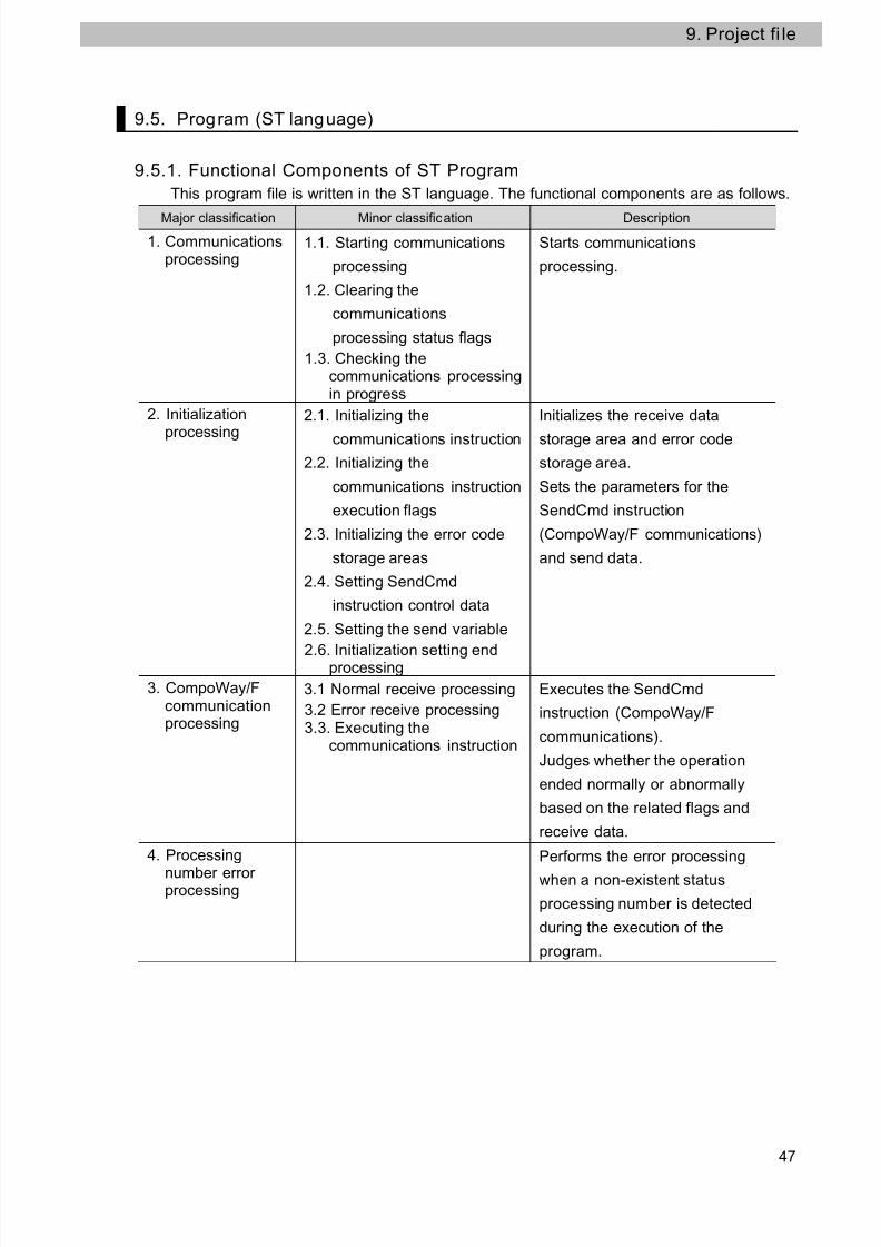
9.5.1. Functional Components of ST Program
This program file is written in the ST language. The functional components are as follows.
Major classification Minor classification Description
1. Communicationsprocessing
1.1. Starting communications
processing
1.2. Clearing the
communications
processing status flags
1.3. Checking thecommunications processingin progress
Starts communications
processing.
2. Initialization
processing
2.1. Initializing the
communications instruction
2.2. Initializing the
communications instruction
execution flags
2.3. Initializing the error code
storage areas
2.4. Setting SendCmd
instruction control data
2.5. Setting the send variable
2.6. Initialization setting endprocessing
Initializes the receive data
storage area and error code
storage area.
Sets the parameters for the
SendCmd instruction
(CompoWay/F communications)
and send data.
3. CompoWay/Fcommunicationprocessing
3.1 Normal receive processing
3.2 Error receive processing3.3. Executing the
communications instruction
Executes the SendCmd
instruction (CompoWay/F
communications).
Judges whether the operation
ended normally or abnormally
based on the related flags and
receive data.
4. Processing
number errorprocessing
Performs the error processing
when a non-existent status
processing number is detected
during the execution of the
program.

7/24/2019 P520-E1-01+NJ Serial Connection Guide for E5CC E5EC E5AC Digital Controller
http://slidepdf.com/reader/full/p520-e1-01nj-serial-connection-guide-for-e5cc-e5ec-e5ac-digital-controller 48/62
9. Project fi le
9.5.2. Detailed Description of Main Program
The following shows the project file.
Communications setting and send data (command), which need to be changed depending
on the destination device, are set in the (CWFCmdsSet) function block. For information on
how to change these values, refer to 9.5.3 Detailed Description of Function Block.
[Main program:Program0]
1. Communications processing
2. Initialization processing
48

7/24/2019 P520-E1-01+NJ Serial Connection Guide for E5CC E5EC E5AC Digital Controller
http://slidepdf.com/reader/full/p520-e1-01nj-serial-connection-guide-for-e5cc-e5ec-e5ac-digital-controller 49/62
9. Project fi le
49
7/24/2019 P520-E1-01+NJ Serial Connection Guide for E5CC E5EC E5AC Digital Controller
http://slidepdf.com/reader/full/p520-e1-01nj-serial-connection-guide-for-e5cc-e5ec-e5ac-digital-controller 50/62
9. Project fi le
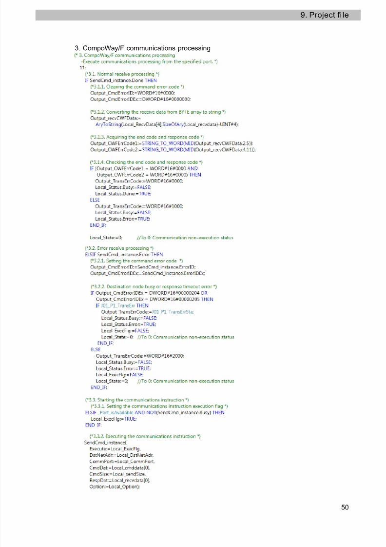
3. CompoWay/F communications processing
50

7/24/2019 P520-E1-01+NJ Serial Connection Guide for E5CC E5EC E5AC Digital Controller
http://slidepdf.com/reader/full/p520-e1-01nj-serial-connection-guide-for-e5cc-e5ec-e5ac-digital-controller 51/62
9. Project fi le
4. Processing number error processing
51

7/24/2019 P520-E1-01+NJ Serial Connection Guide for E5CC E5EC E5AC Digital Controller
http://slidepdf.com/reader/full/p520-e1-01nj-serial-connection-guide-for-e5cc-e5ec-e5ac-digital-controller 52/62
9. Project fi le
52
9.5.3. Detailed Description of Function Block
The following shows the function block of this project file.
Description of CWFCmdsSet function block
Instruction Meaning FB/FUNGraphic
expression ST expression
CWFCmdsSetCompoWay/Fcommunicationssend data setting
FB NoneCWFCmdsSet_instance(Execute,CWFdata, Done);
•In-out variable table (arguments)
•Input
Name Data type Meaning Description Valid range Unit Default
Execute BOOL Execute
The function block is executedwhen this parameter changesfrom OFF (FALSE) to ON(TRUE). (Always: TRUE)
Dependson datatype
- -
•In-out
Name Data type Meaning Description Valid range Unit Default
CWFdataSTRING[256]
Send data Sets the CompoWay/F datasent to the destination device.
Dependson datatype
- -
•Output
Name Data type Meaning Description Valid range Unit Default
Done BOOL Normal endTRUE after execution of thefunction block
Dependson data
type
- -
Busy BOOL Busy
Error BOOL Error end
ErrorID WORDErrorinformation
ErrorIDEx DWORDErrorinformation
Not used(Not used in this project.)
- - -
•Internal variable table
Name Data type Meaning Description Valid range Unit Default
NodeNo STRING[3] Node number.
Sets thecommunications
unit No. of thedestination device.
Depends
on datatype - -
SubAddress STRING[3] Subaddress Not used (optional)Dependson datatype
- -
SID STRING[2] SID Not used (optional)Dependson datatype
- -
MRCSRC STRING[5]Command(MRC+SRC)
Sets the commandcode to use.
Dependson datatype
- -
SendTextSTRING[128]
TextSet the datacorresponding tothe command code.
Dependson datatype
- -

7/24/2019 P520-E1-01+NJ Serial Connection Guide for E5CC E5EC E5AC Digital Controller
http://slidepdf.com/reader/full/p520-e1-01nj-serial-connection-guide-for-e5cc-e5ec-e5ac-digital-controller 53/62
9. Project fi le
•Program
To change the destination device command, edit the code specified by the red frames
on the function block below.
53
7/24/2019 P520-E1-01+NJ Serial Connection Guide for E5CC E5EC E5AC Digital Controller
http://slidepdf.com/reader/full/p520-e1-01nj-serial-connection-guide-for-e5cc-e5ec-e5ac-digital-controller 54/62
9. Project fi le
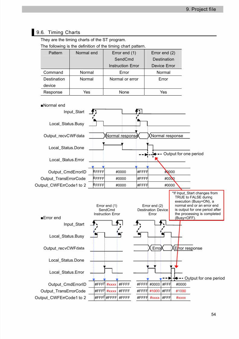
9.6. Timing Charts
They are the timing charts of the ST program.
The following is the definition of the timing chart pattern.
Pattern Normal end Error end (1)
SendCmdInstruction Error
Error end (2)
DestinationDevice Error
Command Normal Error Normal
Destination
device
Normal Normal or error Error
Response Yes None Yes
Normal end
54
Input_Start
Local_Status.Busy
Output_recvCWFdata Normal response Normal response
Local_Status.Done
Output for one period
Local_Status.Error
Output_CmdErrorID FFFF #0000 #FFFF #0000
Output_TransErrorCode FFFF #0000 #FFFF #0000
Output_CWFErrCode1 to 2 FFFF #0000 #FFFF #0000
Error end
Input_Start
Error end (1)SendCmd
Instruction Error
Error end (2)Destination Device
Error
*If Input_Start changes fromTRUE to FALSE duringexecution (Busy=ON), anormal end or an error endis output for one period afterthe processing is completed(Busy=OFF).
Local_Status.Busy
Output_recvCWFdata Error Error response
Local_Status.Done
Local_Status.Error
Output for one period
Output_CmdErrorID #FFF #xxxx #FFFF #FFFF #0000 #FFF #0000
Output_TransErrorCode #FFF #xxxx #FFFF #FFFF #1000 #FFF #1000
Output_CWFErrCode1 to 2 #FFF #FFFF #FFFF #FFFF #xxxx #FFF #xxxx

7/24/2019 P520-E1-01+NJ Serial Connection Guide for E5CC E5EC E5AC Digital Controller
http://slidepdf.com/reader/full/p520-e1-01nj-serial-connection-guide-for-e5cc-e5ec-e5ac-digital-controller 55/62
9. Project fi le
9.7. Error Processing
Error descriptions for this ST program are shown below.
9.7.1. SendCmd Instruction ErrorThese error codes are used at error ends of the SendCmd instruction.
SendCmd instruction error code [Output_CmdErrorID, Output_CmdErrorIDEx]
An error code of ErrorID is stored in Output_CmdsErrorID and an error code of ErrorIDEx
is stored in Output_CmdsErrorIDEx.
[Output_CmdErrorID]
Value Error details
#16#0400 An input parameter for an instruction exceeded the valid range for an input
variable.#16#0406 The data position specified for an instruction exceeded the data area range.
#16#0407 The results of instruction processing exceeded the data area range of the
output parameter.
#16#0800 An error occurred when a command was sent or received.
#16#0801 The port is being used.
Addi ti onal Info rmation
For details on errors, refer to A-3 Error Code Details in the NJ-series Instructions Reference
Manual (Cat. No. W502).
For details on the troubleshooting, refer to 9-3 Troubleshooting of the CJ-series Serial
Communications Units Operation Manual for NJ-series CPU Unit (Cat.No. W494).
55

7/24/2019 P520-E1-01+NJ Serial Connection Guide for E5CC E5EC E5AC Digital Controller
http://slidepdf.com/reader/full/p520-e1-01nj-serial-connection-guide-for-e5cc-e5ec-e5ac-digital-controller 56/62
9. Project fi le
[Output_CmdErrorIDEx]
56

7/24/2019 P520-E1-01+NJ Serial Connection Guide for E5CC E5EC E5AC Digital Controller
http://slidepdf.com/reader/full/p520-e1-01nj-serial-connection-guide-for-e5cc-e5ec-e5ac-digital-controller 57/62
9. Project fi le
57
Transmission error status [Output_TransErrCode]
Data of J01_P1_TransErrSta transmission error status is set in Output_TransErrCode.
Bits 8, 12 and 13 are set when a SendCmd instruction error, destination device error or
processing number error occurs.
[Bit status at a transmission error]
Bit Description15 1:Transmission error 0:No transmission error
13 and 14 (Not used)
13 1:SendCmd instruction error 0:Normal
12 1:Destination device error 0:Normal
9 to 11 (Not used)
8 1:Processing number error 0:Normal
7 1:FCS check error 0:FCS check normal
6 (Not used)
5 1:Timeout error 0:Normal
4 1:Overrun error 0:Normal
3 1:Framing error 0:Normal
2 1:Parity error 0:Normal
0 and 1 (Not used)
#16#0000 and #16#FFFF indicate the following:
Value Description
#16#0000 Normal end
#16#FFFF After initialization processing of the ST program, the program
is not operated yet.

7/24/2019 P520-E1-01+NJ Serial Connection Guide for E5CC E5EC E5AC Digital Controller
http://slidepdf.com/reader/full/p520-e1-01nj-serial-connection-guide-for-e5cc-e5ec-e5ac-digital-controller 58/62
9. Project fi le
58
9.7.2. Destination Device Error
These error codes are used for errors in the destination device.
Output_CWFErrCode1,Output_CWFErrCode2 destination device error code
Output_CWFErrCode1 (End code)Bit 15 8 7 0
#Always #00 #** End code
End
code
Name Description
“00” Normal end The command ended normally without error.
“0F” Command error The specified command could not be executed.
The response code should indicate why the command
could not be executed.“10” Parity error A parity error occurred in a character when receiving.
“11” Framing error A framing error occurred in a character when receiving.
“12” Overrun error An overrun error occurred in a character when receiving.
“13” BCC error The received BCC value is incorrect.
“14” Format error •The command text contains characters other than 0 to 9,
and A to F. This error does not apply to Echoback Tests.
•There was no SID and command text. There was no
command text.
•”MRC/SRC” not included in command text.“16” Sub-address
error
•Illegal (unsupported) sub-address of the receive frame
•There was no sub-address, SID, and command text.
•Sub-address was less than two characters, and there
was no SID and command text
“18” Frame length
error
The received frame exceeds the specified (supported)
number of bytes.
Output_CWFErrCode2 (Response Codes)
Response codes Error name Priority0000 Normal end None
0401 Unsupported command 1
1001 Command too long 2
1002 Command too short 3
1101 Area type error 4
1103 First address out-of-range error 5
1104 End address out-of-range error 6
1003 Number of elements/data mismatch 7
110B Response too long 8
1100 Parameter error 9
3003 Read-only error 10
2203 Operation error 11

7/24/2019 P520-E1-01+NJ Serial Connection Guide for E5CC E5EC E5AC Digital Controller
http://slidepdf.com/reader/full/p520-e1-01nj-serial-connection-guide-for-e5cc-e5ec-e5ac-digital-controller 59/62
9. Project fi le
Addi ti onal Info rmation
For details and troubleshooting the destination device errors, refer to the Digital
Temperature Controllers User's Manual (Cat.No. H175) and the Digital Temperature
Controllers Communications Manual (Cat. No. H174).
59

7/24/2019 P520-E1-01+NJ Serial Connection Guide for E5CC E5EC E5AC Digital Controller
http://slidepdf.com/reader/full/p520-e1-01nj-serial-connection-guide-for-e5cc-e5ec-e5ac-digital-controller 60/62
10. Revision History
60
10. Revision History
Revision
code
Date of revision Revision reason and revision page
01 Jan. 31, 2013 First edition

7/24/2019 P520-E1-01+NJ Serial Connection Guide for E5CC E5EC E5AC Digital Controller
http://slidepdf.com/reader/full/p520-e1-01nj-serial-connection-guide-for-e5cc-e5ec-e5ac-digital-controller 61/62
61

7/24/2019 P520-E1-01+NJ Serial Connection Guide for E5CC E5EC E5AC Digital Controller
http://slidepdf.com/reader/full/p520-e1-01nj-serial-connection-guide-for-e5cc-e5ec-e5ac-digital-controller 62/62