package two stage gas / electric units
TRANSCRIPT

Package Two StageGas / Electric Units
Convertible ModelsYCZ036,050,060F1/3/4
3, 4, 5 Ton
PUB. NO. 22-1684-03-0203 (EN)
RT-PRC020-EN

© 2003 American Standard Inc. All Rights Reserved 2 22-1684-03-0203 (EN)
GeneralFeatures
T-TOP™
COIL-SAV'R™ GRILLS
WEATHERGUARD™Corrosion Resistant Screws
Powder Paint
WATER-SHED™ Base
High Efficiency
2-Climatuff® Compressors
DuraTuff™ Plate Fin Coil
Two Stage Gas Furnace
Side Electrical and GasAccess
Sloped Drain Pan
100% Foil Faced Insulation
Easy Access for Serviceand Installation

22-1684-03-0203 (EN) 3
Contents
Standard Equipment• High Efficiency
IMPACK performance is the highest in theindustry at 16 SEER.
• Two Climatuff® CompressorsTwo Stage CoolingTwo stage operation for full and half coolingcapacity. Protection against chemical,electrical, and mechanical stresses are builtin for efficiency and a longer life. Thecompressors are backed by a 10-yearlimited warranty. (Single phase residentialuse only.)
• Coil GuardsThe COIL-SAV'R end and side grilles are anew Lexan®, louvertype. The grilles willprotect the coil from hail, kids with sticks,and normal shipping, installation andhandling damage.
• Powder PaintBeautiful high gloss silver gray finish blendswith any architectural style. New powderpaint covers surfaces uniformly increasingprotection from rust and corrosion.
• WEATHERGUARD™Corrosion Resistant ScrewsHolds it all together beautifully. Resists rustand corrosion.
• WATER-SHED BaseSuperior water integrity is accomplishedwith the WATER-SHED base pan havingelevated downflow openings and a perim-eter channel that prevents water fromdraining into the ductwork.
• T-TOP™Exclusive one piece, solid unit top forimproved water integrity and easy compo-nent access.
• Two Stage Gas FurnaceThe furnace features aluminized tubularheat exchangers that have demonstratedtheir durability in torturous life cycle tests.The heat exchanger is backed by a 20-yearlimited warranty (residential use only).
(continued on page 4)
Features andBenefits
General Features 2
Features and Benefits 3Standard Equipment 3IMPACK Accessories 5
Selection Procedure 5Model Number Nomenclature 5
Optional Equipment 6
General Data 7YCZ036F1M0B 7YCZ036F3M0B 7YCZ036F4M0A 7YCZ050F1H0A 8YCZ050F3H0A 8YCZ050F4H0A 8YCZ060F1M0B 9YCZ060F3M0B 9YCZ060F4M0A 9
Performance Data 10Cooling 10Heating 13Indoor Fan 14
Sequence Of Operation 15
Optional Equipment 17
Controls 18
Field Wiring 19
Typical Wiring 20
Dimensions 22
Mechanical Specification Options 28

4 22-1684-03-0203 (EN)
Features andBenefits
• VentingInduced draft venting reduces combustionproblems associated with high winds andcombustion panels that have been im-properly replaced.
• California NOxThe standard unit meets California NOxrequirements eliminating the inventoryproblems associated with unique models orkits.
• DuraTuff™ Plate Fin CoilRefrigeration coils are built with internallyenhanced copper tubing for high efficiencywith less coil area.
• One for Us...Two for CustomerThree-try direct spark ignition systemeliminates pilot related problems andprovides unsurpassed ignition reliability.
• Exclusive Comfort-R™ SystemProvides better humidity control in coolingmode.
• CommonalityThe common cabinet among the TCC’s,WCX’s, and YCY’s minimizes both thetraining of sales and service personnel andreplacement parts inventory.
• Easy AccessAll electrical components can be diagnosedand replaced with the removal of one panelthat is attached with two screws.
• FlexibilityA single curb fits the entire IMPACK linefrom 1.5 tons through 5 tons therebyproviding great installation flexibility onshopping malls, factories, schools, andother commercial buildings where a mix-match of tonnages and utilities is desired.
Standard Equipment• Shipping
Unit dimensions were carefully selected toprovide an attractive aspect ratio and forshipping and handling considerations.
• Good NeighborMost units can be installed flush with theresidence or building thereby minimizing theground space required. Blankets ofinsulation reduce blower noise and energylosses to the outside environments.
• Rooftop MountingThe cabinets are physically smaller thanmost competitive models. This means lessintrusive installations on residential rooftopswhere aesthetics are critical.
• ConvertibilityIMPACK units are easily converted fromhorizontal to down flow with the removal ofone screw from each panel. Accordingly,the need to stock both dedicated horizontaland dedicated down flow models has beeneliminated.
• InstallationThe ease of installation and applicationflexibility exhibited through the designreduce both field time and material.
• StructureThe units are lighter weight through the useof high technology components therebyreducing mounting structure requirementsand difficulty when manhandling.
• HandlingThe three-way wooden skid allows for easyloading between the wheel wells on pickuptrucks for transporting to job sites.
• ApplicationThe low profile horizontal duct take-offseliminate the need for expensive transitionducts in crawl space applications.
• Duct FlangesOnly IMPACK has downflow duct flanges forduct attachments that preserve the built-inwater integrity.
• ServiceAll wiring is both numbered and color codedthereby reducing training and servicingcosts related to circuit tracing and compo-nents replacements.
• MaintenanceA plug on the outdoor fan motor allows thetop cover to be removed completely withoutthe hassle of cumbersome wires. Theunique service orifice ring allows the indoorfan motor/blower to be removed as a unit.
• CorrosionThe drain pan is engineered material andeliminates the need for coatings and sealersto prevent sweating and corrosion. Theheavy gauge, zinc-coated steel cabinet hasa weather resistant enamel finish that staysattractive and protects your investment foryears.
• Low Ambient ControlStandard cooling operation to 45° F asshipped, zero degree ambient cooling isaccomplished with two kits. One for low costinstallations when full tonnage is notneeded. The other kit maintains headpressure and full capacity at zero degrees.
• Quality and Reliability TestingWe perform a 100% coil leak test at thefactory. The evaporator and condenser coilsare leak tested at 200 psig and pressuretested to 450 psig respectively. In additionthe IMPACK designs were rigorously raintested at the factory to ensure waterintegrity. Shipping tests are performed todetermine packaging requirements. Factoryshake and drop tests are used as part of thepackage design process to help assure thatthe unit will arrive at the job site in topcondition. Additionally, all components areinspected at the point of final assembly.Substandard parts and components areidentified and rejected immediately. Everyunit receives a 100% run test before leavingthe production line to make sure it lives upto rigorous Trane requirements. We at Tranetest our designs at our factory and not onour customers!

22-1684-03-0203 (EN) 5
PRODUCTSERVICE CHANGE
MINOR DESIGNMODIFICATION
FACTORY INSTALLED OPTIONSEXAMPLES:0 = No factory installed optionsN = Filter Frame*
* Product Deviation Required
AUXILIARY HEATING CAPACITYL = Low HeatM = Medium HeatH = High Heat0 = No Heat
ELECTRICAL CHARACTERISTICS1 = 208-230/60/13 = 208-230/60/34 = 460/60/3
IMPACKAccessories
1 2 3 4 5 6 7 8 9 10 11 12Y C Z 0 3 6 F 1 M 0 A A
PRODUCT TYPEYC = Packaged Gas/ElectricTC = Packaged CoolingWC = Packaged Heat PumpsDC = Dual Fuel
AIRFLOW CONFIGURATIONC = ConvertibleD = DownflowH = HorizontalM = Manufactured HousingX = High EfficiencyY = 12-14 SEERZ = 15-16 SEER
NOMINAL NET COOLINGCAPACITY (MBH)036 = 3 Tons050 = 4.25 Tons060 = 5 Tons
MAJOR DEVELOPMENT SEQUENCEF = IMPACK
Model Number Nomenclature
Selection Procedure
• Standard ThermostatsNo special thermostats are needed withIMPACK units.
• Filter Frame KitThe IMPACK filter frames accept standardfilters and fit inside the unit. The frame kitsfunction in either horizontal or downflowduct configurations.
• UNI-CURBOne universal curb fits all the IMPACKmodels. It ships knocked down. The curbdesign incorporates the popular locking tabsfor quick and easy assembly. Full perimetercurbs are also available for all models.
• EconomizerThe economizer fits inside the unit with onlythe rain hood and barometric relief on theoutside. Cabling is shipped with theeconomizer. This cabling is easily routed tothe control box where it terminates in lowvoltage pigtails. The economizer features afully modulating low voltage motor eliminat-ing the need for any high voltage wiring. Theeconomizer must be used with the filterframe kit...no return air filter in the econ-omizer kit. A dry bulb sensor is shipped withthe economizer. The downflow economizerwas not designed for use in horizontalapplications. A horizontal only economizer isavailable. Heat pump applications require arelay kit.
• Enthalpy Control KitFor those applications specifying aneconomizer with enthalpy control, thiscontrol can be used in place of the dry bulbsensor or, alternately, two enthalpy controlscan be paired to provide differential enthalpycontrol.
• Outside Air Control for V.S. EconomizerThe BAYOSAC001 board has 5 adjustmentports for controlling outside air setting forfirst and second stage heating and coolingand fan continuous airflow.
• 25% Fresh Air KitThe kit installs over the horizontal return airopening with six screws for downflowrequirements. It can be used on horizontalair flow applications by cutting a hole in thereturn air duct or in the unit filter accesspanel.
• Rectangular to Round Duct KitsThe adapter kit can be used in eitherhorizontal or downflow applications.
• Propane KitsOne propane kit fits all the IMPACK models.This kit has been constructed for greatestfield flexibility and to minimize the number ofparts that have to be discarded.
• Low Ambient KitAn EDC provides low ambient cooling to0° F with some reduced capacity andprotects the system against evaporator icingduring other unusual cooling conditions.
• Head Pressure Control KitThis kit includes a solid state outdoor motorcontrol, junction box, and wiring. It providesfull capacity down to 0° F.
• Lifting Lug KitFour reusable lugs in each kit allow units tobe easily lifted to rooftop installations. Theselugs snap (no screws required) into slots inthe unit drip lip channel.

6 22-1684-03-0203 (EN)
OptionalEquipment
OPTIONAL EQUIPMENT FOR PACKAGED UNITS(check mark [✓✓✓✓✓] indicates accessories included)
Indoor Thermostats — Prog. Auto. 2-Stage Htg/CIg w/ Econ. ......................... TAYSTAT302C [ ]Electronic 2 Htg/2 Clg Auto (Non-prog.) ......................... TAYSTAT375 [ ]
Outdoor Temp. Sensor (TAYSTAT302C,375) ................................................... TAYSENS100A [ ]Locking Thermostat Cover (Thermostats) .............................................................BAY28X190 [ ]Humidistat ...........................................................................................................BAYSTAT253 [ ]Roof Curb Full Perimeter (YCZ036F) 3 ........................................................ BAYCURB033A [ ]Roof Curb Full Perimeter (YCZ050-60F) 3 ................................................... BAYCURB034A [ ]0-25% Manual Fresh Air Damper (YCZ036F) 1 ............................................ BAYDMPR040A [ ]0-25% Manual Fresh Air Damper (YCZ050-60F) 1 ...................................... BAYDMPR041A [ ]12" Round Duct Adapter (2 per box) (YCZ036F) ............................................ BAYDUCT004A [ ]14" Round Duct Adapter (1 per box) (YCZ036F) ............................................ BAYDUCT005A [ ]0-100% Mod Economizer w/Baro. Relief (YCZ036F) 124 .......................... BAYECON054B [ ]0-100% Mod. Economizer w/Baro. Relief (YCZ050-60F) 124 .................... BAYECON055B [ ]0-100% Horizontal Economizer 12 .............................................................. BAYECON073A [ ]Enthalpy Control for Economizer (solid state). ................................................ BAYENTH001A [ ]Remote Potentiometer (BAYECON054,055A,073A) ........................................... BAYSTAT023 [ ]Outside Air Control for V.S.Economizer ........................................................... BAYOSAC001A [ ]Filter Frame (YCYZ036F) (20x25x1) 1 ........................................................... BAYFLTR013A [ ]Filter Frame (YCZ050-60F) (3-10x25x1) 1 ...................................................... BAYFLTR014A [ ]Filter Frame (YCZ036F) (20x25x2) 1 ............................................................. BAYFLTR018A [ ]Filter Frame (YCZ050-60F) (2-16x25x2) 1 ...................................................... BAYFLTR019A [ ]LP Conversion Kit ............................................................................................BAYLPKT024A [ ]LP Conversion Kit w/Stainless Steel Burners ................................................. BAYLPSS002A [ ]Lifting Lug Kit .................................................................................................... BAYLlFT002A [ ]Evaporator Defrost Control (Low Ambient Cooling) Kit .................................. BAYLOAM011A [ ]Head Pressure Control (Low Ambient Cool) (208/240v) Kit 5 ...................... BAYLOAM323A [ ]Low Ambient Motor (208/230) 5 ................................................................... BAYMOTR307A [ ]Low Ambient Motor (460v) 5 ........................................................................ BAYMOTR406A [ ]Notes:1 Must use filter frame when economizer/fresh air kit is used.2 Dry bulb control standard with economizer.3 Ships knocked down.4 Downflow only.5 Use Low Ambient Motor With This Kit on YCZ036F models.
22-1684-03-0203 (EN) 7
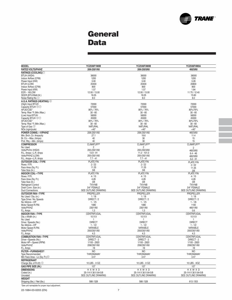
GeneralData
MODELRATED VOLTS/PH/HZRATINGS (COOLING)1BTUH (HIGH)Indoor Airflow (CFM)Power Input (KW)BTUH (LOW)Indoor Airflow (CFM)Power Input (KW)EER - HI/LOWSEER (BTU/Watt-Hr.)Noise Rating No.1A.G.A. RATINGS (HEATING) 2(High) Input BTUHCapacity BTUH 57AFUE/CSE*Temp. Rise °F. (Min./Max.)(Low) Input BTUHCapacity BTUH 57AFUE/CSE*Temp. Rise °F. (Min./Max.)Type of Gas 3NOx (ngm/joule)POWER CONNS.—V/PH/HZMin. Brch. Cir. AmpacityBr. Cir.—Max. (Amps)Prot. Rtq.—Min. (Amps)COMPRESSORNo. UsedVolts/Ph/Hz (HIGH)R.L. Amps—L.R. AmpsVolts/PH/HZ (LOW)R.L. Amps—L.R. AmpsOUTDOOR COIL—TYPERows / F.P.I.Face Area (Sq. Ft.)Tube Size (In.)INDOOR COIL—TYPERows / F.P.I.Face Area (Sq. Ft.)Tube Size (In.)Refrigerant ControlDrain Conn. Size (in.)Duct ConnectionsOUTDOOR FAN—TYPENo. Used / Dia. (in.)Type Drive / No. SpeedsNo. Motors—HPMotor Speed R.P.M.Volts/PH/HZF.L. AmpsINDOOR FAN—TYPEDia. x Width (in.)No. UsedDrive / Speeds (No.)No. Motors—HPMotor Speed R.P.M.Volts/PH/HZF.L. AmpsCOMBUSTION FAN—TYPEDrive—Speeds (No.)Motor HP—Speed (RPM)Volts/PH/HZF.L. AmpsFILTER—FURNISHED?Type RecommendedMin Face Area - Lo (Sq. Ft.)6REFRIGERANTCharge (lbs. of R-22) 4GAS PIPE SIZE (IN.)DIMENSIONSCrated (in.)UncratedWEIGHTShipping (lbs.) / Net (lbs.)
YCZ036F1M0B208-230/1/60
3600012003.00
204008001.57
12.00 / 13.0016.058.0
7200057000
80% / 76%30 - 605600045000
80% / 76%30 - 60
NATURAL<40*
208-230/1/6027.14040
CLIMATUFF®
2200-230/1/60
13.9 - 91200-230/1/60
7.7 - 41PLATE FIN
2 / 2211.353/8
PLATE FIN4 / 154.283/8
TXV-NB3/4" FEMALE
SEE OUTLINE DRAWINGPROPELLER
1 / 18DIRECT / 2
1 - 1/51080
230/1/601.3
CENTRIFUGAL10 X 9
1DIRECT1 - 1/2
VARIABLE200/230/1/60
4.3CENTRIFUGAL
DIRECT - 21/100 - 2920208/230/1/60
.18NO
THROWAWAY3.47
10 LBS. , 0 OZ.1/2"
H X W X D35-1/4 X 38 X 64-5/8
SEE OUTLINE DRAWING
588 / 528
YCZ036F3M0B208-230/3/60
3600012003.00
204008001.57
12.00 / 13.0016.058.0
7200057000
80% / 76%30 - 605600045000
80% / 76%30 - 60
NATURAL<40*
208-230/1/6019.63030
CLIMATUFF®
2200-230/3/6011.2 - 101.0200-230/1/60
7.7 - 41PLATE FIN
2 / 2211.353/8
PLATE FIN4 / 154.283/8
TXV-NB3/4" FEMALE
SEE OUTLINE DRAWINGPROPELLER
1 / 18DIRECT / 2
1 - 1/51080
230/1/601.3
CENTRIFUGAL10 X 9
1DIRECT1 - 1/2
VARIABLE200/230/1/60
4.3CENTRIFUGAL
DIRECT - 21/100 - 2920208/230/1/60
.18NO
THROWAWAY3.47
10 LBS. , 0 OZ.1/2"
H X W X D35-1/4 X 38 X 64-5/8
SEE OUTLINE DRAWING
588 / 528
YCZ036F4M0A460/3/60
3600012003.28
208008001.64
11.70 / 12.4015.608.0
7200057000
80%/76%30 - 605600045000
80%/76%30 - 60
NATURAL<40*
460/3/6011.41515
CLIMATUFF®
2460/3/606.4 - 46460/3/603.2 - 31
PLATE FIN2 / 2211.353/8
PLATE FIN4 / 154.283/8
TXV-NB3/4" FEMALE
SEE OUTLINE DRAWINGPROPELLER
1 / 18DIRECT / 2
1 - 1/61100
460/1/600.6
CENTRIFUGAL10 X 9
1DIRECT1 - 1/2
VARIABLE200/230/1/60
4.3CENTRIFUGAL
DIRECT - 21/100 - 2920208/230/1/60
.18NO
THROWAWAY3.47
10 LBS. , 0OZ.1/2"
H X W X D35-1/4 X 38 X 64-5/8
SEE OUTLINE DRAWING
613 / 553
*See unit nameplate for proper input adjustment.

8 22-1684-03-0203 (EN)
MODELRATED VOLTS/PH/HZRATINGS (COOLING)1BTUH (HIGH)Indoor Airflow (CFM)Power Input (KW)BTUH (LOW)Indoor Airflow (CFM)Power Input (KW)EER - HI/LOWSEER (BTU/Watt-Hr.)Noise Rating No.1A.G.A. RATINGS (HEATING) 2(High) Input BTUHCapacity BTUH 57AFUE/CSE*Temp. Rise °F. (Min./Max.)(Low) Input BTUHCapacity BTUH 57AFUE/CSE*Temp. Rise °F. (Min./Max.)Type of Gas 3NOx (ngm/joule)POWER CONNS.—V/PH/HZMin. Brch. Cir. AmpacityBr. Cir.—Max. (Amps)Prot. Rtq.—Min. (Amps)COMPRESSORNo. UsedVolts/Ph/Hz (HIGH)R.L. Amps—L.R. AmpsVolts/PH/HZ (LOW)R.L. Amps—L.R. AmpsOUTDOOR COIL—TYPERows / F.P.I.Face Area (Sq. Ft.)Tube Size (In.)INDOOR COIL—TYPERows / F.P.I.Face Area (Sq. Ft.)Tube Size (In.)Refrigerant ControlDrain Conn. Size (in.)Duct ConnectionsOUTDOOR FAN—TYPENo. Used / Dia. (in.)Type Drive / No. SpeedsNo. Motors—HPMotor Speed R.P.M.Volts/PH/HZF.L. AmpsINDOOR FAN—TYPEDia. x Width (in.)No. UsedDrive / Speeds (No.)No. Motors—HPMotor Speed R.P.M.Volts/PH/HZF.L. AmpsCOMBUSTION FAN—TYPEDrive—Speeds (No.)Motor HP—Speed (RPM)Volts/PH/HZF.L. AmpsFILTER—FURNISHED?Type RecommendedMin Face Area - Lo (Sq. Ft.)6REFRIGERANTCharge (lbs. of R-22) 4GAS PIPE SIZE (IN.)DIMENSIONSCrated (in.)UncratedWEIGHTShipping (lbs.) / Net (lbs.)
YCZ050F4H0A460/3/60
5100016004.44
2900010002.13
11.5 / 13.7015.758.2
12000095000
80%/76%35 - 659000073000
80%/76%30 - 60
NATURAL<40*
460/3/6015.12020
CLIMATUFF®
2460/3/603.9 - 31460/3/603.9 - 31
PLATE FIN2 / 2215.03/8
PLATE FIN4 / 155.43/8
TXV-NB3/4" FEMALE
SEE OUTLINE DRAWINGPROPELLER
1 / 24DIRECT / 2
1 - 1/4825
460/1/600.9
CENTRIFUGAL11 X 11
1DIRECT1 - 3/4
VARIABLE200/230/1/60
6.8CENTRIFUGAL
DIRECT - 21/45 - 2800208/230/1/60
.22NO
THROWAWAY5.33
11.8 LBS.1/2"
H X W X D39-3/8 X 47X 64-1/4
SEE OUTLINE DRAWING
718 / 651
YCZ050F1H0A208-230/1/60
5100016004.43
2800010002.00
11.5 / 14.0016.008.2
12000095500
80% / 76%35 - 659000073000
80% / 76%35 - 65
NATURAL<40*
208-230/1/60324040
CLIMATUFF®
2200-230/1/60
8.7 - 62200-230/1/60
8.7 - 62PLATE FIN
2 / 2215.03/8
PLATE FIN4 / 155.43/8
TXV-NB3/4" FEMALE
SEE OUTLINE DRAWINGPROPELLER
1 / 24DIRECT / 2
1 - 1/4840
230/1/602.0
CENTRIFUGAL11 X 11
1DIRECT1 - 3/4
VARIABLE200/230/1/60
6.8CENTRIFUGAL
DIRECT - 21/45 - 2800
208/230/1/60.22NO
THROWAWAY5.33
11.8 LBS.1/2"
H X W X D39-3/8 X 47 X 64-1/4
SEE OUTLINE DRAWING
693 / 626
YCZ050F3H0A208-230/3/60
5100016004.43
2800010002.00
11.5 / 14.016.008.2
12000095500
80% / 76%35 - 659000073000
80% / 76%35 - 65
NATURAL<40*
208-230/1/6025.53030
CLIMATUFF®
2200-230/3/60
7.4 - 61200-230/3/60
7.4 - 61PLATE FIN
2 / 2215.03/8
PLATE FIN4 / 155.43/8
TXV-NB3/4" FEMALE
SEE OUTLINE DRAWINGPROPELLER
1 / 24DIRECT / 2
1 - 1/4840
230/1/602.0
CENTRIFUGAL11 X 11
1DIRECT1 - 3/4
VARIABLE200/230/1/60
6.8CENTRIFUGAL
DIRECT - 21/45 - 2800208/230/1/60
.22NO
THROWAWAY5.33
11.8 LBS.1/2"
H X W X D39-3/8 X 47 X 64-1/4
SEE OUTLINE DRAWING
693 / 626
GeneralData
*See unit nameplate for proper input adjustment.

22-1684-03-0203 (EN) 9
MODELRATED VOLTS/PH/HZRATINGS (COOLING)1BTUH (HIGH)Indoor Airflow (CFM)Power Input (KW)BTUH (LOW)Indoor Airflow (CFM)Power Input (KW)EER - HI/LOWSEER (BTU/Watt-Hr.)Noise Rating No.1A.G.A. RATINGS (HEATING) 2(High) Input BTUHCapacity BTUH 57AFUE/CSE*Temp. Rise °F. (Min./Max.)(Low) Input BTUHCapacity BTUH 57AFUE/CSE*Temp. Rise °F. (Min./Max.)Type of Gas 3NOx (ngm/joule)POWER CONNS.—V/PH/HZMin. Brch. Cir. AmpacityBr. Cir.—Max. (Amps)Prot. Rtq.—Min. (Amps)COMPRESSORNo. UsedVolts/Ph/Hz (HIGH)R.L. Amps—L.R. AmpsVolts/PH/HZ (LOW)R.L. Amps—L.R. AmpsOUTDOOR COIL—TYPERows / F.P.I.Face Area (Sq. Ft.)Tube Size (In.)INDOOR COIL—TYPERows / F.P.I.Face Area (Sq. Ft.)Tube Size (In.)Refrigerant ControlDrain Conn. Size (in.)Duct ConnectionsOUTDOOR FAN—TYPENo. Used / Dia. (in.)Type Drive / No. SpeedsNo. Motors—HPMotor Speed R.P.M.Volts/PH/HZF.L. AmpsINDOOR FAN—TYPEDia. x Width (in.)No. UsedDrive / Speeds (No.)No. Motors—HPMotor Speed R.P.M.Volts/PH/HZF.L. AmpsCOMBUSTION FAN—TYPEDrive—Speeds (No.)Motor HP—Speed (RPM)Volts/PH/HZF.L. AmpsFILTER—FURNISHED?Type RecommendedMin Face Area - Lo (Sq. Ft.)6REFRIGERANTCharge (lbs. of R-22) 4GAS PIPE SIZE (IN.)DIMENSIONSCrated (in.)UncratedWEIGHTShipping (lbs.) / Net (lbs.)
GeneralData
*See unit nameplate for proper input adjustment.
1 Certified in accordance withthe Unitary Air-ConditionerEquipment certificationprogram, which is based onARI Standard 210/240. Noisecalculated in accordance withA.R.I. Standard 270. A.R.I. stan-dard rating conditions are:80 D.B. 67 W.B. entering air toindoor coil. 95 D.B. entering airto outdoor coil.
2 All models are UL Listed. Ratingsshown are for elevations up to2000 ft. For higher elevations re-duce ratings at a rate of 4% per1000 ft. elevation.
3 Convertible to LPG.
4 This value is approximate.For more precise value, seeUnit Nameplate.
5 Based on U.S. GovernmentStandard Tests.
6 Filters must be installed in returnair stream. Square footages listedare based on 300 f.p.m. facevelocity. If permanent filters areused size per manufacturer'srecommendation with a cleanresistance of 0.05" W.C.
7 Check Unit Nameplate Unit for asshipped input, unit is convertiblewith a factory supplied orificechange to other input.
YCZ060F1M0B208-230/1/60
5900020005.36
2980011002.29
11.0 / 13.015.208.2
12000096000
80% / 76%30 - 609000072000
80% / 76%30 - 60
NATURAL<40*
208-230/1/6043.57070
CLIMATUFF®
2200-230/1/6022.1 - 145.0200-230/1/60
11.0 - 57PLATE FIN
2 / 2215.03/8
PLATE FIN4 / 155.43/8
TXV-NB3/4" FEMALE
SEE OUTLINE DRAWINGPROPELLER
1 / 24DIRECT / 2
1 - 1/4840
230/1/602.0
CENTRIFUGAL11 X 11
1DIRECT
1 - 1VARIABLE
200/230/1/606.9
CENTRIFUGALDIRECT - 21/45 - 2800
208/230/1/60.22NO
THROWAWAY6.67
12 LBS, 13 OZ.1/2"
H X W X D39-3/8 X 47X 64-1/4
SEE OUTLINE DRAWING
723 / 656
YCZ060F3M0B208-230/3/60
5900020005.36
2980011002.29
11.0 / 13.015.208.2
12000096000
80% / 76%30 - 609000072000
80% / 76%30 - 60
NATURAL<40*
208-230/1/6030.94545
CLIMATUFF®
2200-230/3/6017.6 - 118.0200-230/1/60
11.0 - 57PLATE FIN
2 / 2215.03/8
PLATE FIN4 / 155.43/8
TXV-NB3/4" FEMALE
SEE OUTLINE DRAWINGPROPELLER
1 / 24DIRECT / 2
1 - 1/4840
230/1/602.0
CENTRIFUGAL11 X 11
1DIRECT
1 - 1VARIABLE
200/230/1/606.9
CENTRIFUGALDIRECT - 21/45 - 2800208/230/1/60
.22NO
THROWAWAY6.67
12 LBS, 13 OZ.1/2"
H X W X D39-3/8 X 47X 64-1/4
SEE OUTLINE DRAWING
723 / 650
YCZ060F4M0A460/3/60
5900020005.47
2920011002.23
10.90 / 13.1814.858.2
12000096000
80%/76%30 - 609000072000
80%/76%30 - 60
NATURAL<40*
460/3/6020.33030
CLIMATUFF®
2460/3/6010.3 - 71460/3/603.9 - 31
PLATE FIN2 / 2215.03/8
PLATE FIN4 / 155.43/8
TXV-NB3/4" FEMALE
SEE OUTLINE DRAWINGPROPELLER
1 / 24DIRECT / 2
1 - 1/4825
460/1/600.9
CENTRIFUGAL11 X 11
1DIRECT
1 - 1VARIABLE
200/230/1/606.9
CENTRIFUGALDIRECT - 21/45 - 2800208/230/1/60
.22NO
THROWAWAY6.67
12 LBS, 13 OZ.1/2"
H X W X D39-3/8 X 47X 64-1/4
SEE OUTLINE DRAWING
748 / 675

10 22-1684-03-0203 (EN)
Performance DataCooling
YCZ036F—B AT 1200 CFM(CAPACITIES ARE NET IN BTUH/1000-INDOOR FAN HEAT DEDUCTED)
O.D. I.D. TOTAL SENS. CAP. AT ENTERING D.B. TEMP. COMPR. APP.DEWD.B. W.B. CAP. 72 74 76 78 80 KW PT.
59 36.4 27.8 30.0 32.1 34.2 36.3 2.33 43.485 63 38.8 23.6 25.7 27.8 29.9 32.0 2.36 47.4
67 41.4 18.9 21.0 23.1 25.2 27.3 2.40 51.771 44.0 14.0 16.1 18.3 20.4 22.5 2.44 56.159 33.8 26.7 28.8 31.0 33.1 34.3* 2.35 44.6
90 63 36.2 22.5 24.6 26.7 28.8 30.9 2.39 48.667 38.7 17.8 19.9 22.1 24.2 26.3 2.44 52.971 41.2 13.0 15.2 17.3 19.4 21.5 2.49 57.259 31.3 25.6 27.7 29.8 31.5* 32.3* 2.37 45.9
95 63 33.6 21.4 23.5 25.6 27.8 29.9 2.42 49.867 36.0 16.8 18.9 21.0 23.1 25.3 2.48 54.071 38.4 12.1 14.2 16.3 18.4 20.5 2.54 58.359 28.7 24.5 26.6 28.7* 29.5* 30.2* 2.39 47.1
100 63 30.9 20.3 22.4 24.6 26.7 28.8 2.45 51.067 33.3 15.8 17.9 20.0 22.1 24.2 2.52 55.171 35.7 11.1 13.2 15.3 17.4 19.6 2.58 59.459 26.2 23.4 25.5 26.7* 27.4* 28.2* 2.41 48.3
105 63 28.3 19.2 21.4 23.5 25.6 27.7 2.48 52.167 30.6 14.7 16.8 19.0 21.1 23.2 2.56 56.371 32.9 10.1 12.2 14.3 16.5 18.6 2.63 60.559 21.0 21.2* 21.9* 22.7* 23.4* 24.1* 2.46 50.7
115 63 23.1 17.1 19.2 21.3 23.4* 24.1* 2.54 54.567 25.2 12.7 14.8 16.9 19.0 21.1 2.63 58.671 27.4 8.1 10.3 12.4 14.5 16.6 2.73 62.7
CORRECTION FACTORS - OTHER AIRFLOWS(multiply or add as indicated)
AIRFLOW 1050 1350TOTAL CAP. X0.99 X1.01SENS. CAP. X0.95 X1.05COMPR. KW X1.00 X1.00A.D.P. -1.5 +1.2
VALUES AT ARI RATING CONDITIONS
TOTAL NET CAPACITY = 36000 BTUHAIRFLOW = 1200 CFMAPP. DEW PT. = 54.0 DEG. FCOMPRESSOR POWER = 2480 WATTSI.D. FAN POWER = 280 WATTSO.D. FAN POWER = 240 WATTS
* DRY COIL CONDITION (TOTAL CAPACITY =SENSIBLE CAPACITY)TOTAL CAPACITY, COMP. KW AND APP. DEW PT.ARE VALID ONLY FOR WET COILALL TEMPERATURES IN DEGREES F.
YCZ036F—B AT 800 CFM(CAPACITIES ARE NET IN BTUH/1000-INDOOR FAN HEAT DEDUCTED)
O.D. I.D. TOTAL SENS. CAP. AT ENTERING D.B. TEMP. COMPR. APP.DEWD.B. W.B. CAP. 72 74 76 78 80 KW PT.
59 20.0 16.9 18.3 19.7 20.4* 20.9* 1.09 47.185 63 21.5 14.1 15.5 16.9 18.4 19.8 1.11 51.1
67 23.0 11.1 12.5 13.9 15.3 16.7 1.13 55.371 24.6 7.9 9.3 10.7 12.1 13.6 1.15 59.659 18.8 16.4 17.8 18.9* 19.4* 19.9* 1.15 47.9
90 63 20.2 13.6 15.0 16.4 17.9 19.3 1.17 51.867 21.7 10.6 12.0 13.4 14.8 16.2 1.19 56.071 23.2 7.5 8.9 10.3 11.7 13.1 1.22 60.359 17.5 15.9 17.3 17.9* 18.4* 18.9* 1.21 48.7
95 63 18.9 13.1 14.5 15.9 17.3 18.8 1.23 52.667 20.4 10.1 11.5 12.9 14.3 15.7 1.26 56.871 21.9 7.0 8.4 9.8 11.2 12.6 1.29 61.159 16.3 15.3 16.5* 16.9* 17.4* 17.9* 1.27 49.6
100 63 17.7 12.6 14.0 15.4 16.8 17.9* 1.30 53.467 19.1 9.6 11.0 12.4 13.8 15.2 1.33 57.671 20.5 6.5 7.9 9.4 10.8 12.2 1.36 61.859 15.1 14.8 15.5* 15.9* 16.4* 16.9* 1.33 50.4
105 63 16.4 12.1 13.5 14.9 16.4* 16.9* 1.36 54.267 17.8 9.1 10.5 11.9 13.4 14.8 1.39 58.371 19.2 6.1 7.5 8.9 10.3 11.7 1.42 62.559 12.6 13.0* 13.5* 13.9* 14.4* 14.8* 1.45 52.0
115 63 13.8 11.1 12.5 13.9* 14.4* 14.8* 1.48 55.867 15.2 8.2 9.6 11.0 12.4 13.8 1.52 59.971 16.5 5.1 6.6 8.0 9.4 10.8 1.56 64.0
CORRECTION FACTORS - OTHER AIRFLOWS(multiply or add as indicated)
AIRFLOW 700 900TOTAL CAP. X0.99 X1.01SENS. CAP. X0.94 X1.06COMPR. KW X1.00 X1.00A.D.P. -1.3 +1.0
VALUES AT ARI RATING CONDITIONS
TOTAL NET CAPACITY = 20400 BTUHAIRFLOW = 800 CFMAPP. DEW PT. = 56.8 DEG. FCOMPRESSOR POWER = 1260 WATTSI.D. FAN POWER = 80 WATTSO.D. FAN POWER = 230 WATTS
* DRY COIL CONDITION (TOTAL CAPACITY =SENSIBLE CAPACITY)TOTAL CAPACITY, COMP. KW AND APP. DEW PT.ARE VALID ONLY FOR WET COILALL TEMPERATURES IN DEGREES F.

22-1684-03-0203 (EN) 11
Performance DataCooling
YCZ050F—A AT 1600 CFM(CAPACITIES ARE NET IN BTUH/1000-INDOOR FAN HEAT DEDUCTED)
O.D. I.D. TOTAL SENS. CAP. AT ENTERING D.B. TEMP. TOTAL APP. DEWD.B. W.B. CAP. 72 74 76 78 80 KW PT.
59 46.2 36.4 39.4 42.3 45.3 47.1* 3.93 45.285 63 49.8 30.7 33.6 36.6 39.5 42.5 4.00 49.1
67 53.7 24.4 27.3 30.3 33.2 36.2 4.08 53.371 57.6 17.9 20.9 23.8 26.8 29.7 4.16 57.559 45.1 35.9 38.9 41.8 44.8 46.2* 4.10 45.6
90 63 48.6 30.2 33.1 36.1 39.1 42.0 4.18 49.567 52.3 23.9 26.8 29.8 32.7 35.7 4.26 53.671 56.2 17.4 20.4 23.3 26.3 29.2 4.34 57.959 44.0 35.5 38.4 41.4 44.2* 45.3* 4.28 45.9
95 63 47.4 29.7 32.7 35.6 38.6 41.5 4.35 49.867 51.0 23.4 26.3 29.3 32.2 35.2 4.43 54.071 54.7 16.9 19.9 22.8 25.8 28.7 4.51 58.359 42.7 35.0 37.9 40.9 43.2* 44.3* 4.46 46.3
100 63 46.1 29.2 32.1 35.1 38.1 41.0 4.53 50.267 49.5 22.8 25.8 28.8 31.7 34.7 4.60 54.471 53.1 16.4 19.3 22.3 25.2 28.2 4.68 58.759 41.5 34.5 37.4 40.4 42.2* 43.3* 4.65 46.7
105 63 44.7 28.7 31.6 34.6 37.5 40.5 4.71 50.667 48.1 22.3 25.3 28.2 31.2 34.1 4.78 54.871 51.5 15.8 18.8 21.8 24.7 27.7 4.85 59.159 39.1 33.4 36.4 39.3* 40.2* 41.2* 5.03 47.4
115 63 42.0 27.6 30.6 33.5 36.5 39.4 5.08 51.367 45.2 21.3 24.2 27.2 30.1 33.1 5.13 55.571 48.4 14.8 17.7 20.7 23.6 26.6 5.18 59.8
CORRECTION FACTORS - OTHER AIRFLOWS(multiply or add as indicated)
AIRFLOW 1400 1600TOTAL CAP. X0.98 X1.00SENS. CAP. X0.94 X1.00COMPR. KW X0.99 X1.00A.D.P. -1.4 0.0
VALUES AT ARI RATING CONDITIONS
TOTAL NET CAPACITY = 51000 BTUHAIRFLOW = 1600 CFMAPP. DEW PT. = 54.0 DEG. FCOMPRESSOR POWER = 3720 WATTSI.D. FAN POWER = 310 WATTSO.D. FAN POWER = 400 WATTS
* DRY COIL CONDITION (TOTAL CAPACITY =SENSIBLE CAPACITY)TOTAL CAPACITY, COMP. KW AND APP. DEW PT.ARE VALID ONLY FOR WET COILALL TEMPERATURES IN DEGREES F.
YCZ050F—A AT 1000 CFM(CAPACITIES ARE NET IN BTUH/1000-INDOOR FAN HEAT DEDUCTED)
O.D. I.D. TOTAL SENS. CAP. AT ENTERING D.B. TEMP. TOTAL APP.DEWD.B. W.B. CAP. 72 74 76 78 80 KW PT.
59 25.6 20.1 21.8 23.6 25.4 26.2* 1.81 45.285 63 27.6 16.6 18.4 20.2 21.9 23.7 1.82 49.1
67 29.6 12.9 14.6 16.4 18.1 19.9 1.83 53.471 31.7 9.0 10.8 12.6 14.3 16.1 1.84 57.759 25.0 19.9 21.6 23.4 25.1* 25.7* 1.91 45.5
90 63 26.9 16.4 18.2 19.9 21.7 23.4 1.91 49.467 28.8 12.6 14.4 16.1 17.9 19.6 1.92 53.771 30.8 8.8 10.5 12.3 14.0 15.8 1.92 58.059 24.4 19.7 21.4 23.2 24.6* 25.2* 2.00 45.7
95 63 26.2 16.2 17.9 19.7 21.4 23.2 2.00 49.767 28.0 12.3 14.1 15.9 17.6 19.4 2.00 54.071 29.9 8.5 10.2 12.0 13.8 15.5 2.00 58.459 23.8 19.4 21.2 22.9 24.1* 24.7* 2.10 46.0
100 63 25.4 15.9 17.6 19.4 21.2 22.9 2.10 50.067 27.1 12.1 13.8 15.6 17.3 19.1 2.09 54.371 28.9 8.2 9.9 11.7 13.5 15.2 2.08 58.759 23.1 19.2 20.9 22.7 23.5* 24.1* 2.21 46.3
105 63 24.7 15.6 17.4 19.1 20.9 22.7 2.19 50.367 26.3 11.8 13.5 15.3 17.1 18.8 2.18 54.771 28.0 7.9 9.7 11.4 13.2 14.9 2.16 59.059 21.7 18.7 20.4 21.9* 22.4* 22.9* 2.43 46.9
115 63 23.1 15.1 16.9 18.6 20.4 22.1 2.39 51.067 24.6 11.2 13.0 14.8 16.5 18.3 2.35 55.371 26.1 7.3 9.1 10.9 12.6 14.4 2.31 59.7
CORRECTION FACTORS - OTHER AIRFLOWS(multiply or add as indicated)
AIRFLOW 875 1000TOTAL CAP. X0.98 X1.00SENS. CAP. X0.93 X1.00COMPR. KW X1.00 X1.00A.D.P. -1.2 0.0
VALUES AT ARI RATING CONDITIONS
TOTAL NET CAPACITY = 28000 BTUHAIRFLOW = 1000 CFMAPP. DEW PT. = 54.0 DEG. FCOMPRESSOR POWER = 1580 WATTSI.D. FAN POWER = 120 WATTSO.D. FAN POWER = 300 WATTS
* DRY COIL CONDITION (TOTAL CAPACITY =SENSIBLE CAPACITY)TOTAL CAPACITY, COMP. KW AND APP. DEW PT.ARE VALID ONLY FOR WET COILALL TEMPERATURES IN DEGREES F.

12 22-1684-03-0203 (EN)
Performance DataCooling
YCZ060F—B AT 2000 CFM(CAPACITIES ARE NET IN BTUH/1000-INDOOR FAN HEAT DEDUCTED)
O.D. I.D. TOTAL SENS. CAP. AT ENTERING D.B. TEMP. COMPR. APP.DEWD.B. W.B. CAP. 72 74 76 78 80 KW PT.
59 54.8 43.7 47.2 50.7 54.3 55.8* 3.91 46.285 63 58.5 36.6 40.1 43.6 47.1 50.7 3.98 50.2
67 62.5 28.8 32.3 35.8 39.4 42.9 4.05 54.571 66.4 20.8 24.3 27.8 31.4 34.9 4.12 58.859 53.2 43.0 46.5 50.0 53.3* 54.5* 4.07 46.6
90 63 56.8 35.9 39.4 42.9 46.5 50.0 4.15 50.667 60.7 28.1 31.6 35.2 38.7 42.2 4.24 54.971 64.6 20.2 23.7 27.2 30.7 34.3 4.32 59.259 51.6 42.3 45.8 49.4 52.0* 53.2* 4.23 47.0
95 63 55.2 35.2 38.7 42.3 45.8 49.3 4.32 51.067 59.0 27.5 31.0 34.5 38.0 41.6 4.42 55.371 62.8 19.5 23.0 26.6 30.1 33.6 4.52 59.759 50.0 41.6 45.1 48.7 50.8* 51.9* 4.39 47.5
100 63 53.5 34.5 38.1 41.6 45.1 48.7 4.49 51.567 57.3 26.8 30.3 33.9 37.4 40.9 4.60 55.771 61.0 18.9 22.4 25.9 29.5 33.0 4.72 60.159 48.4 40.9 44.5 48.0 49.5* 50.6* 4.55 47.9
105 63 51.9 33.9 37.4 40.9 44.5 48.0 4.66 51.967 55.5 26.1 29.7 33.2 36.7 40.3 4.79 56.171 59.2 18.2 21.8 25.3 28.8 32.4 4.92 60.559 45.3 39.6 43.1 45.8* 46.9* 48.0* 4.86 48.8
115 63 48.6 32.5 36.1 39.6 43.1 46.6 5.01 52.867 52.1 24.8 28.4 31.9 35.4 39.0 5.16 57.071 55.6 17.0 20.5 24.0 27.6 31.1 5.31 61.3
CORRECTION FACTORS - OTHER AIRFLOWS(multiply or add as indicated)
AIRFLOW 1750 2250TOTAL CAP. X0.99 X1.01SENS. CAP. X0.94 X1.05COMPR. KW X1.00 X1.00A.D.P. -1.5 +1.2
VALUES AT ARI RATING CONDITIONS
TOTAL NET CAPACITY = 59000 BTUHAIRFLOW = 2000 CFMAPP. DEW PT. = 55.3 DEG. FCOMPRESSOR POWER = 4420 WATTSI.D. FAN POWER = 540 WATTSO.D. FAN POWER = 400 WATTS
* DRY COIL CONDITION (TOTAL CAPACITY =SENSIBLE CAPACITY)TOTAL CAPACITY, COMP. KW AND APP. DEW PT.ARE VALID ONLY FOR WET COILALL TEMPERATURES IN DEGREES F.
YCZ060F—B AT 1100 CFM(CAPACITIES ARE NET IN BTUH/1000-INDOOR FAN HEAT DEDUCTED)
O.D. I.D. TOTAL SENS. CAP. AT ENTERING D.B. TEMP. COMPR. APP.DEWD.B. W.B. CAP. 72 74 76 78 80 KW PT.
59 28.1 23.5 25.4 27.4 28.5* 29.2* 1.57 47.585 63 30.1 19.7 21.6 23.5 25.5 27.4 1.59 51.4
67 32.3 15.4 17.4 19.3 21.3 23.2 1.62 55.671 34.4 11.1 13.0 15.0 16.9 18.9 1.64 60.059 26.9 23.0 25.0 26.9 27.6* 28.2* 1.68 48.0
90 63 28.9 19.2 21.1 23.1 25.0 26.9 1.70 52.067 31.0 15.0 16.9 18.9 20.8 22.7 1.73 56.271 33.1 10.7 12.6 14.5 16.5 18.4 1.76 60.559 25.8 22.5 24.5 26.0* 26.7* 27.3* 1.78 48.6
95 63 27.7 18.7 20.6 22.6 24.5 26.5 1.81 52.567 29.8 14.5 16.5 18.4 20.3 22.3 1.84 56.771 31.9 10.2 12.2 14.1 16.0 18.0 1.87 61.059 24.7 22.0 24.0 25.1* 25.7* 26.4* 1.88 49.1
100 63 26.6 18.2 20.2 22.1 24.1 26.0 1.91 53.067 28.6 14.1 16.0 17.9 19.9 21.8 1.95 57.271 30.6 9.8 11.7 13.7 15.6 17.5 1.99 61.559 23.5 21.6 23.5* 24.2* 24.8* 25.4* 1.98 49.7
105 63 25.4 17.8 19.7 21.6 23.6 25.4* 2.02 53.667 27.3 13.6 15.5 17.5 19.4 21.4 2.06 57.871 29.3 9.3 11.3 13.2 15.2 17.1 2.10 62.059 21.2 20.6 21.7* 22.3* 23.0* 23.6* 2.19 50.8
115 63 23.0 16.8 18.8 20.7 22.6 23.6* 2.24 54.767 24.9 12.7 14.6 16.6 18.5 20.4 2.29 58.871 26.8 8.5 10.4 12.3 14.3 16.2 2.34 63.1
CORRECTION FACTORS - OTHER AIRFLOWS(multiply or add as indicated)
AIRFLOW 975 1250TOTAL CAP. X0.99 X1.01SENS. CAP. X0.95 X1.06COMPR. KW X1.00 X1.00A.D.P. -1.2 +1.1
VALUES AT ARI RATING CONDITIONS
TOTAL NET CAPACITY = 29800 BTUHAIRFLOW = 1100 CFMAPP. DEW PT. = 56.7 DEG. FCOMPRESSOR POWER = 1840 WATTSI.D. FAN POWER = 110 WATTSO.D. FAN POWER = 340 WATTS
* DRY COIL CONDITION (TOTAL CAPACITY =SENSIBLE CAPACITY)TOTAL CAPACITY, COMP. KW AND APP. DEW PT.ARE VALID ONLY FOR WET COILALL TEMPERATURES IN DEGREES F.
22-1684-03-0203 (EN) 13
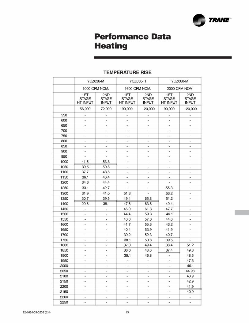
Performance DataHeating
YCZ036-M YCZ050-H YCZ060-M
1000 CFM NOM. 1600 CFM NOM. 2000 CFM NOM
1STSTAGE
HT INPUT
2NDSTAGEINPUT
1STSTAGE
HT INPUT
2NDSTAGEINPUT
1STSTAGE
HT INPUT
2NDSTAGEINPUT
56,000 72,000 90,000 120,000 90,000 120,000
550 - - - - - -600 - - - - - -650 - - - - - -700 - - - - - -750 - - - - - -800 - - - - - -850 - - - - - -900 - - - - - -950 - - - - - -1000 41.5 53.3 - - - -1050 39.5 50.8 - - - -1100 37.7 48.5 - - - -1150 36.1 46.4 - - - -1200 34.6 44.4 - - - -
1250 33.1 42.7 - - 55.3 -
1300 31.9 41.0 51.3 - 53.2 -1350 30.7 39.5 49.4 65.8 51.2 -1400 29.6 38.1 47.6 63.6 49.4 -1450 - - 46.0 61.3 47.7 -1500 - - 44.4 59.3 46.1 -1550 - - 43.0 57.3 44.6 -1600 - - 41.7 55.6 43.2 -1650 - - 40.4 53.9 41.9 -1700 - - 39.2 52.3 40.7 -1750 - - 38.1 50.8 39.5 -1800 - - 37.0 49.4 38.4 51.21850 - - 36.0 48.0 37.4 49.81900 - - 35.1 46.8 - 48.51950 - - - - - 47.32000 - - - - - 46.12050 - - - - - 44.982100 - - - - - 43.92150 - - - - - 42.92200 - - - - - 41.92150 - - - - - 40.9
2200 - - - - - -2250 - - - - - -
TEMPERATURE RISE

14 22-1684-03-0203 (EN)
Performance DataIndoor Fan

22-1684-03-0203 (EN) 15
SequenceOf Operation
Operation of the unit heating or cooling cycles is controlled by thesetting of the system switch on the room thermostat. Once the systemswitch is placed either in the “HEAT” or “COOL” position, unit operationis automatic. A fan switch on the thermostat also provides for itscontinuous operation of the evaporator fan when desired. The fanswitch “ON” position provides continuous operation while the “AUTO”position provides operation during the heating or cooling cycles.
HEATING CYCLEThermostat call for heat (2-stage thermostat)
Call for 1st stage only:(R) and (W1) thermostat contacts close signaling the control module(IGN) to run its self-check routine. After the control has verified that thepressure switch (PS) contacts are open, the limit switch (TCO) contactsare closed, and the flame rollout (FL) switch is closed, the induced draftblower (CBM) will be energized on high speed for approximately5 seconds.
After the induced draft blower (CBM) has come up to speed, the controlwill verify that the pressure switch (PS) contacts are closed and switchthe induced draft blower to low speed for 10-second prepurge. The gasvalve (GV) is energized in the first stage to permit gas flow and thespark ignitor (IP) is energized. The flame detector (FD) confirms thatignition has been achieved within the 7 second trial period.
As the flame detector confirms that ignition has been achieved thedelay to indoor fan on period begins timing and after approximately45 seconds, the indoor blower motor (IDM) will be energized at lowspeed and will continue to run during the heating cycle.
Call for 2nd stage after 1st stage:(R) and (W2) thermostat contacts close signaling a call for secondstage heat. The induced draft motor (CBM) is energized on high speedand the gas valve on second stage. After approximately 30 seconds thecontrol energizes the indoor blower on high speed.
2nd stage satisfied, 1st stage still called:(R) and (W2) opens, the induced draft blower is reduced to low speed,the gas valve is reduced to first stage. After aprox. 30 seconds theindoor blower motor is reduced to low speed.
1st stage satisfied:(R) and (W1) opens, the gas valve (GV) will close. The induced draftblower (CBM) will be de-energized after approximately 5 secondspostpurge. The indoor blower motor (IDM) will continue to run for thefan off period (field selectable 60 or 90 seconds [by dip switch]), thenwill be de-energized by the control module.
Thermostat satisfied:(R) and (W1/W2) (jumpered) contacts open signaling the controlmodule to close the gas valve and de-energize the induced draft blowerafter approximately 5 second postpurge. The I.D. blower motor willcontinue to operate at the current speed for 60 or 90 seconds after theflames are extinguished.
SAFETY SEQUENCESThis product is equipped with safety devices to protect againstabnormal conditions.
The temperature limit switch (TCO) is located in the gas compartmenton the vestibule panel above the burner assembly. This automatic resetdevice protects against excessive leaving air temperature. If this deviceopens, the gas valve is immediately closed and will not permit opera-tion until the limit switch closes.
The rollout switch (FS) is located in the gas compartment near the inletof the burners. This is a single use device designed to protect againstany form of flame rollout. If this device is opened the gas valve isimmediately de-energized and the control (IGN) will lockout the system.
The rollout switch (FS) must be replaced before operation is allowed tocontinue.
The pressure switch (PS) is located in the upper right side of the gascompartment. This automatic device assures adequate combustion airpressure. If pressure against the induced draft blower outlet becomesexcessive, the pressure switch will react and shut off the gas valve,until acceptable combustion pressure is again available.
If the control (IGN) does not sense flame within the first trial for ignitionperiod. The gas valve will be de-energized. The control (IGN) will initiatea 60 seconds interpurge. Following the interpurge, on the second trialthe gas valve will be energized on second stage (high heat input). If theflame is sensed within 10 seconds after the second try and only a callfor first stage exists, the gas valve will be reduced to first stage. If thesecond try is not successful. The control will start another 60 secondinterpurge. After the interpurge, a third attempt will be tried. The gasvalve will be energized on second stage (high heat input). If the flame issensed within 10 seconds after the third try and only a call for firststage exists, the gas valve will be reduced to first stage. If the third tryis not successful, the control will lock out.
If loss of flame occurs during a heating cycle, the control (IGN) willclose the gas valve. The control will then recycle the ignition sequence,then if ignition is not achieved, it will shut off the gas valve and lock outthe system.
If control lock out occurs, the control (IGN) will retry a complete ignitionsequence in 2 hours.
The control (IGN) can be reset by removing power to the unit or byturning the thermostat from “on” to “off" for approximately threeseconds, then back “on.”
COOLING CYCLEThermostat call for cool (2-stage thermostat)
Call for 1st stage only:With the room thermostat system switch in the “COOLING” positionand the fan switch in the “AUTO” position, the Y1 thermostat contactcloses to the micro board (the board will wait 3 seconds to check if theY2 may also be calling) the micro will energize (CC1) and the outdoorfan relay for low speed and the G thermostat contact to G-IGN and toG1 on the ICMC is energized. (The status light is flashing and theY1 light is on.)
The energized compressor contactor (CC1) completes the circuit to thecompressor (CPR1). If the compressor safety controls are closed, thecompressor (CPR1) will operate with the outdoor fan motor (ODM) onlow speed. The indoor fan motor (IDM) will operate on low speed. Thethermostat will continue to cycle the compressor and fans to maintainthe desired temperature.
With the thermostat fan switch in the “ON” position, the G thermostatcontact is closed to G1 on the ICMC board and the indoor fan motor(IDM) will continue to run on low speed regardless of compressor andcondenser fan operation.
Call for 2nd stage after 1st stage:The Y2 thermostat contact closes to the control board. For 1 minuteboth compressors are off (all lights are flashing for 1 minute), then theboard will energize the (CC2) compressor contactor, and the outdoorfan relay for high speed, then the board (YCZ050 ONLY - will energizethe (CC1) and 1 second later the (CC2) compressor contactors) andthe indoor fan high to the Y on the ICMC board is energized for indoorhigh speed fan operation. (The status light is flashing and the Y1 andY2 lights are on.)

16 22-1684-03-0203 (EN)
SequenceOf Operation
ICM FAN CONTROL
DIP SWITCHES (TYPICAL SETTINGS)
JUMPERBK
CFM SELECTIONLIGHT (GREEN)
DIP SWITCHES
FOR HUMIDISTAT
COOLING OFF - DELAY OPTIONS
SWITCH SETTINGS SELECTION NOMINALAIRFLOW
5 - OFF 6 - OFF NONE SAME
5 - ON 6 - OFF 1.5 MINUTES 100% *
5 - OFF 6 - ON 3 MINUTES 50%
5 - ON 6 - ON ENHANCED** 50 - 100%
* - This setting is equivalent to the BAY24X045 relay benefit
** - This ENHANCED MODE selection provides a ramping up and ramping downof the blower speed to provide improved comfort, quietness, and potential energysavings. The graph shows the ramping process.
OFF OFF
25%
40%
25% DehumidifyWarm Air Heating
Fast Coil CoolingFast Coil Heating
EnhancedEfficiency
7.5minutes
3minutes
(Fan Only)
1minute
SY
ST
EM
AIR
FL
OW
(C
FM
) 50%
80%
50%
100%
Only if required
SECOND STAGE
FIRST STAGE
50% Only if required
EnhancedComfort
COMPRESSOR OPERATION ON OFF
2nd stage satisfied, 1st stage still called: (YCZ036,060F ONLY)The Y2 thermostat contact opens to the control board. For 1 minuteboth compressors are off (the status and Y1 light are flashing for1 minute), then the board will energize (CC1) low compressorcontactor, and the outdoor fan relay for low speed and indoor fan for lowspeed. (The status light is flashing and the Y1 light is on.)
2nd stage satisfied, 1st stage still called: (YCZ050 ONLY)The Y2 thermostat contact opens to the control board. The board willde-energize (CC2) second compressor contactor, and energize theoutdoor fan relay for low speed and indoor fan for low speed. (Thestatus light is flashing and the Y1 light is on.)
ICM FAN MOTOR ADJUSTMENTSIf the airflow needs to be increased or decreased, see the IndoorBlower Performance Table below. Information on changing the dipswitch settings for speed control of the blower motor is in this table.
Blower speed changes are made on the ICM Fan Control mounted inthe control box. The ICM Fan Control controls the variable speed motor.
There is a bank of 8 dip switches (See Figure below), located at thelower right side of the board. The dip switches work in pairs to selectthe cooling/heat airflow (CFM/TON), and Fan off-delay options.
INDOOR BLOWER TIMINGThe ICM Fan Control controls the variable speed indoor blower. TheFAN-OFF period is set on the ICM Fan Control board by dip switches#5 and #6. The delay settings of the blower are as follows:

22-1684-03-0203 (EN) 17
OptionalEquipment
BAYECONO73A Horizontal Economizer and Rain Hood
From Dwg. 21D662056 Rev. 0

18 22-1684-03-0203 (EN)
Economizer Pressure Drop — (Return Air Restriction 0% Outdoor Air)
AIRFLOW(CFM)
BAYECON054B(in. H20)
BAYECON055Bin. (H20)
BAYECON073A(in. H20)
600 .010 .010800 .020 .0151000 .050 .0201200 .090 .040 .0251400 .140 .050 .0301600 .075 .0351800 .100 .0452000 .130 .0552200 .150 .0752400 .190 .100
From Dwg. 21A730983 Rev. 1
OptionalEquipment
Economizer and Rain Hood(Downflow Applications)
Controls
Field Installed Control OptionsThermostatsTwo stages heating/cooling or one stageheating/cooling thermostats are available ineither manual or automatic changeover.
Programmable Electronic Night SetbackThermostatHeating setback and cooling setup with 7-day,5-1-1 programming capability. Available in 2heating/cooling or 1 heating/cooling versionswith automatic changeover.
Economizer ControlsThe standard equipment offering is a fixed drybulb changeover control. In addition to thestandard offering, there are two other fieldinstalled control accessories.
Enthalpy ControlReplaces the dry bulb control with a solidstate dry bulb and wet bulb changeovercontroller which has a fully adjustable setpoint. Enthalpy control offers a higher level of
energy savings potential than the standard drybulb control due to the additional wet bulbsensing capability.
Differential EnthalpyReplaces the standard dry bulb control withtwo enthalpy sensors that compare total heatcontent of the indoor air and outdoor air todetermine the most efficient entering airsource. This control option offers the highestlevel of energy efficiency available.
ECONOMIZERMODEL
APPLICATIONMODELS A B C D E F G H
BAYECON054B YCZ036F 20 16-5/8 23-1/2 22-9/16 8-5/8 22-1/4 25-1/8 1-1/2
BAYECON055B YCZ050FYCZ060F 20 21 26 OMIT 12-1/8 26-1/8 32-1/8 1-3/4

22-1684-03-0203 (EN) 19
FieldWiring
From Dwg. 21C757231

20 22-1684-03-0203 (EN)
TypicalWiring
(continued on next page) From Dwg. 21D757316 P05

22-1684-03-0203 (EN) 21
TypicalWiring
From Dwg. 21D757316 P05

22 22-1684-03-0203 (EN)
Dimensions
BAYCURB033A Roof Mounting Curb Outline YCZ036F — Unit
From Dwg. 21C662039
Required Clearance for Unit Installation and Roof Penetration Hole Size Required
AIR DUCTOPENINGS A B C
SUPPLYDUCT 21 16-3/4 -
RETURNDUCT 21 - 21-1/8
SERVICE CLEARANCE DIMENSIONS
A B C D
30" 30" *12" 30"
*18" WITH 25% FRESH AIR ACCESSORY 30" WITH ECONOMIZER
C662035
INSUL. DECK
44"25"
A
B
C
D
INSUL. DECK

22-1684-03-0203 (EN) 23
Dimensions
BAYCURB034A Roof Mounting Curb Outline YCZ050,060F — Units
From Dwg. 21C662038
Required Clearance for Unit Installation and Roof Penetration Hole Size Required
SERVICE CLEARANCE DIMENSIONS
A B C D
42" 30" *12" 36"
*18" WITH 25% FRESH AIR ACCESSORY 30" WITH ECONOMIZER
AIR DUCTOPENINGS A B C
SUPPLYDUCT 21 19 -
RETURNDUCT 21 - 22-1/8
A
BC
D
C662034
INSUL.DECK

24 22-1684-03-0203 (EN)
Dimensions
Field Fabricated (Side X Side) Ducts — YCZ036,050,060F UnitsInstalled from Above Mounting Curb
P.V.C. Rubber Gasket Position on BAYCURB033,034A for Unit Placement —YCZ036,050,060F Units
NOTES:1. OVERLAP AND POSITION JOINTS IN P.V.C. RUBBER
GASKET.2. AIR SEALS – APPLY P.V.C. RUBBER LAST TO INSURE
THERE IS ADEQUATE P.V.C. FOR THE WATER SEAL.3. USE TYPICAL SEALING METHODS TO PREVENT AIR
DUCT LEAKAGE AT CURB-DUCT JOINT.

22-1684-03-0203 (EN) 25
Dimensions
YCZ036,050,060F OUTLINE DRAWING — FrontNOTE: ALL DIMENSIONS ARE IN INCHES
CABINETSIZE
MODEL BAYCURB "A" "B" "C" "D" "E" "F" "G" "H"
"C" YCZ036F-H 033A 14-13/16 16-5/8 36 34 29-3/16 13-3/4 -- --
"D"YCZ050F-HYCZ060F-M
034A 14-13/16 21 45 43 33-3/8 13-3/4 -- --
From Dwg. 21D661772

26 22-1684-03-0203 (EN)
Dimensions
YCZ036,050,060F OUTLINE DRAWING — RearNOTE: ALL DRAWING DIMENSIONS ARE IN MM (INCHES)
From Dwg. 21D667953
MODELCORNER WEIGHT (LBS)
NETUNIT
WEIGHT(LBS)
A B C D E F G H J K L M N PW1 W2 W3 W4
YCZ036F 161 106 104 157 528 64 36 29-3/16 18-9/16 11-1/16 6-9/16 11-1/8 17 18-1/2 25-1/2 17-1/2 10 3 8-3/4
YCZ050F 172 121 137 196 62665-1/8 45 33-3/8 21-1/16 15-1/16 4-15/16 9-1/8 21-15/16
24 26-1/220 14 3-1/2 8-5/16
YCZ060F 195 129 132 199 656 22-3/4 25-1/2
NOTE: TABLE IN INCHES ONLY.

22-1684-03-0203 (EN) 27
Dimensions
YCZ036,050,060F OUTLINE DRAWING — FrontNOTE: ALL DRAWING DIMENSIONS ARE IN MM (INCHES)
From Dwg. 21D667952
MODEL A B C D
YCZ036F-M 64 36 29-3/16 27-1/2
YCZ050F-HYCZ060F-M 65-1/8 45 33-3/8 27-15/16
NOTE: TABLE IN INCHES ONLY.
CLEARANCE TO COMBUSTIBLE MATERIAL
BOTTOM 0.0"
BACK 1.0"
LEFT SIDE 6.0"
RIGHT SIDE 6.0"
FRONT SIDE 12.0"
TOP 36.0"
NOTE: TABLE IN INCHES ONLY.
RECOMMENDED SERVICE CLEARANCE
BACK * 6.0"
LEFT SIDE 30.0"
RIGHT SIDE 24.0"
FRONT SIDE 30.0"
* 18" WITH FRESH AIR ACCESSORY * 30" WITH ECONOMIZER
NOTE: TABLE IN INCHES ONLY.

P.I.
Trane has a policy of continuous product and product data improvement and it reserves the right to changedesign and specifications without notice.
TraneA business ofAmerican Standard Companieswww.trane.com
MechanicalSpecification Options
GeneralAll units shall be factory assembled, piped,internally wired and fully charged with R-22.All units shall be designed to operate atoutdoor ambient temperatures as high as115°F. Cooling capacities shall be rated inaccordance with A.R.I. standards. The YCZ-Fheating/cooling unit design is UL listed,specifically for outdoor applications usingpropane or natural gas. All units shall bedesigned for outdoor rooftop or ground levelinstallation. Exterior surfaces of all units shallbe phosphatized, zinc-coated steel with epoxyresin primer and baked enamel finish.Shipped for horizontal application,convertible to downflow.
CasingsAll panels shall be 20-gauge steel, gasketedand insulated. Foil-faced glass fiber insulationshall be in the heat exchanger section. Mat-faced insulation shall be in the evaporatorsection. Base pan and mounting rails shall be18 gauge. WEATHERGUARD™ exteriorcorrosion resistant screws shall be used foradded resistance to rust and corrosion.
Coil GuardsThe COIL-SAV'R™ end and side grilles shallbe Lexan®, louvertype. The grilles shall protectthe coil from hail, sticks, and handling damage.
ControlsRefrigeration cycle controls shall includecondenser fan, evaporator fan and compres-sor contactors. Compressors shall beequipped with a combination internal windingthermostat/current overload. Internal highpressure relief shall also be provided.Comfort-R™ System shall provide betterhumidity control in the cooling mode.
Refrigeration SystemCompressors — All units shall havehermetically sealed Climatuff® compressors.Compressors shall be equipped with over
temperature, over current and high pressureprotection. Crankcase heaters shall bestandard on all three phase models.
Evaporator Coil — Internally enhanced3/8-inch OD seamless copper tubing me-chanically bonded to aluminum fins, factorypressure and leak tested at 250 to 300 psig.
Condenser Coil — Outdoor coils shall beinternally enhanced 3/8-inch OD seamlesscopper tubing mechanically bonded toaluminum fins. Each coil shall be factorypressure and leak tested at 420 psig.
Indoor Air Fan — Direct-drive, forward-curved, centrifugal type. Motor shall havethermal overload protection. Permanentlylubricated motor bearings. Motor/blowerassembly isolated from unit with rubbermounts.
Condenser Fan — Direct-drive, draw thrupropeller type. Weather-proofed permanentsplit capacitor fan motor shall have built-inthermal overload and permanently lubricatedmotor bearings.
Low Ambient — Standard refrigerant systemoperation down to 55°F. Low ambientaccessory required for operation in 0°F.ambient condition.
Heating SystemGas-Fired Heating Section — Models shallprovide completely assembled, wired andpiped gas fired heating systems within unit.Design certified by U.L., specifically foroutdoor application. Threaded gas connectionon the unit.
Electronic Ignition System — Main burner islit each time thermostat calls for heat. Flamesensor proves flame and keeps the mainburners on. Should a loss of flame occur, themain valve closes and the spark recurs within0.8 second. When thermostat is satisfied,main burner is extinguished.
Forced Combustion Blower — Insuresflame stability under varying wind conditions.Gives higher combustion efficiency andlocation flexibility.
Heat Exchanger — Aluminized steel tubes.Free floating design.
Burners — 20-gauge aluminized steel. Multi-port inshot.
AccessoriesRoof Curb — The roof curb shall be designedto mate with the unit and provide support andcomplete weather-tight installation whenproperly installed. Curb shall ship knockeddown for field assembly, and include woodnailer strips.
Modulating Economizer — This accessoryshall be field installed and be composed of thefollowing items: 0-100% fresh air damper,damper drive motor fixed dry bulb enthalpycontrol, and low voltage polarized plug forelectrical connections. Solid state enthalpy ordifferential enthalpy control is optional.Economizer operations shall be controlled bythe preset position of the enthalpy control. Abarometric relief damper shall be standardwith the economizer and provide a pressureoperated damper that shall be gravity closingand prohibit entrance of outside air onequipment “off” cycle.
Manual Fresh Air Hood — Manual outsideair provides a fixed outside air quantity from0 to 25 percent. Includes hood and birdscreen.
Low Ambient Control — Control allowscycling of compressor under low ambientcooling conditions. Required for coolingoperation to 0°F.
Propane Gas Conversion Kit — Forconversion from natural gas to LP gas.
Literature Order Number 22-1684-03-0203 (EN)
File Number PL-UN-RT-PRC020-EN 02/03
Supersedes YCZ-D-1 07/00
Stocking Location Webb/Mason-Houston