packaged l series lca/lga/lha · 2019-11-07 · features item lca/lga 156h lca/lga/lha 180 lca/lga...
TRANSCRIPT
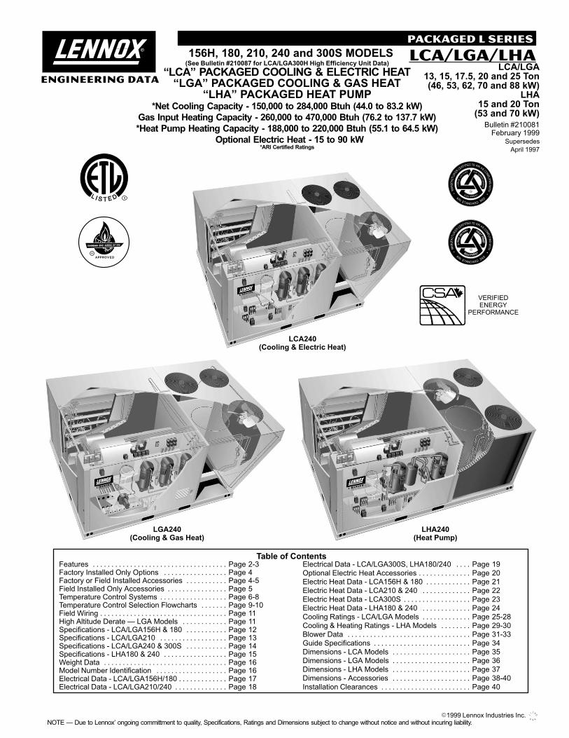
LCA240(Cooling & Electric Heat)
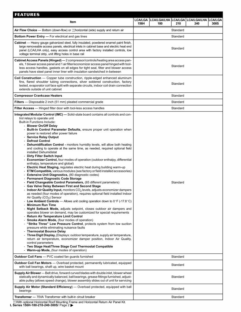
LGA240(Cooling & Gas Heat)
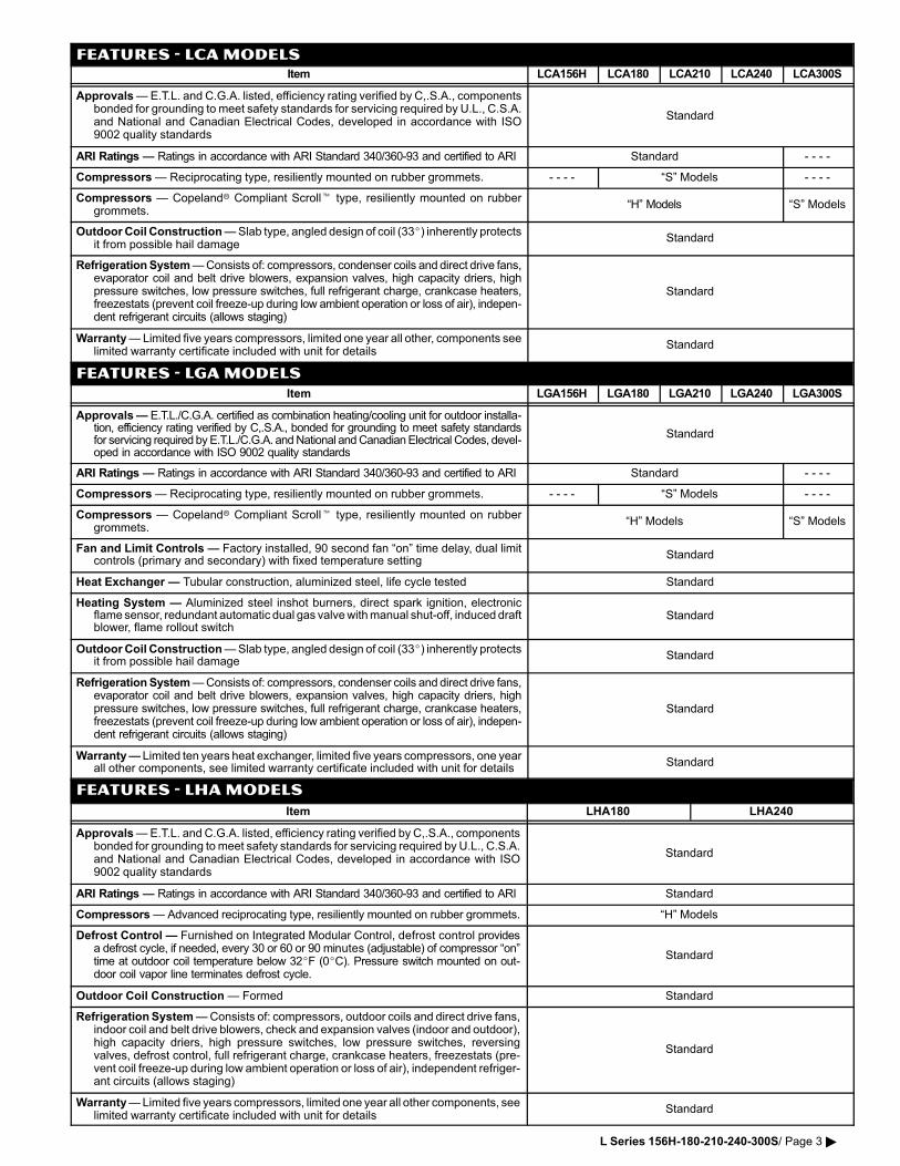
LHA240(Heat Pump)
PACKAGED �L" SERIES
Table of ContentsFeatures Page 2−3. . . . . . . . . . . . . . . . . . . . . . . . . . . . . . . . . . . . Factory Installed Only Options Page 4. . . . . . . . . . . . . . . . . Factory or Field Installed Accessories Page 4−5. . . . . . . . . . . Field Installed Only Accessories Page 5. . . . . . . . . . . . . . . . Temperature Control Systems Page 6−8. . . . . . . . . . . . . . . . . . Temperature Control Selection Flowcharts Page 9−10. . . . . . . Field Wiring Page 11. . . . . . . . . . . . . . . . . . . . . . . . . . . . . . . . . . High Altitude Derate � LGA Models Page 11. . . . . . . . . . . . Specifications − LCA/LGA156H & 180 Page 12. . . . . . . . . . . Specifications − LCA/LGA210 Page 13. . . . . . . . . . . . . . . . . . Specifications − LCA/LGA240 & 300S Page 14. . . . . . . . . . . Specifications − LHA180 & 240 Page 15. . . . . . . . . . . . . . . . . Weight Data Page 16. . . . . . . . . . . . . . . . . . . . . . . . . . . . . . . . . Model Number Identification Page 16. . . . . . . . . . . . . . . . . . . Electrical Data − LCA/LGA156H/180 Page 17. . . . . . . . . . . . . Electrical Data − LCA/LGA210/240 Page 18. . . . . . . . . . . . . .
Electrical Data − LCA/LGA300S, LHA180/240 Page 19. . . .
Optional Electric Heat Accessories Page 20. . . . . . . . . . . . . . Electric Heat Data − LCA156H & 180 Page 21. . . . . . . . . . . .
Electric Heat Data − LCA210 & 240 Page 22. . . . . . . . . . . . .
Electric Heat Data − LCA300S Page 23. . . . . . . . . . . . . . . . . .
Electric Heat Data − LHA180 & 240 Page 24. . . . . . . . . . . . . Cooling Ratings − LCA/LGA Models Page 25−28. . . . . . . . . . . . .
Cooling & Heating Ratings − LHA Models Page 29−30. . . . . . . .
Blower Data Page 31−33. . . . . . . . . . . . . . . . . . . . . . . . . . . . . . . . .
Guide Specifications Page 34. . . . . . . . . . . . . . . . . . . . . . . . . .
Dimensions − LCA Models Page 35. . . . . . . . . . . . . . . . . . . . . Dimensions − LGA Models Page 36. . . . . . . . . . . . . . . . . . . . .
Dimensions − LHA Models Page 37. . . . . . . . . . . . . . . . . . . . .
Dimensions − Accessories Page 38−40. . . . . . . . . . . . . . . . . . . . .
Installation Clearances Page 40. . . . . . . . . . . . . . . . . . . . . . . .
VERIFIEDENERGY
PERFORMANCE
�LCA" PACKAGED COOLING & ELECTRIC HEAT�LGA" PACKAGED COOLING & GAS HEAT
�LHA" PACKAGED HEAT PUMP*Net Cooling Capacity − 150,000 to 284,000 Btuh (44.0 to 83.2 kW)
Gas Input Heating Capacity − 260,000 to 470,000 Btuh (76.2 to 137.7 kW)
*Heat Pump Heating Capacity − 188,000 to 220,000 Btuh (55.1 to 64.5 kW)
�Optional Electric Heat − 15 to 90 kW
Bulletin #210081February 1999
Supersedes
April 1997
LCA/LGA13, 15, 17.5, 20 and 25 Ton(46, 53, 62, 70 and 88 kW)
LHA15 and 20 Ton(53 and 70 kW)
*ARI Certified Ratings
LCA/LGA/LHAPACKAGED L SERIES
ENGINEERING DATA
(See Bulletin #210087 for LCA/LGA300H High Efficiency Unit Data)
156H, 180, 210, 240 and 300S MODELS
�� �1999 Lennox Industries Inc.NOTE � Due to Lennox’ ongoing committment to quality, Specifications, Ratings and Dimensions subject to change without notice and without incuring liability.
FEATURES
ItemLCA/LGA156H
LCA/LGA/LHA180
LCA/LGA210
LCA/LGA/LHA240
LCA/LGA300S
Air Flow Choice � Bottom (down�flow) or �horizontal (side) supply and return air Standard
Bottom Power Entry � For electrical and gas lines Standard
Cabinet � Heavy gauge galvanized steel, fully insulated, powdered enamel paint finish,
large removeable access panels, electrical inlets in cabinet base and electric heat end
panel (LCA/LHA only), easy access control area with factory installed controls, low
voltage terminal strip, unit lifting holes in base rail
Standard
Cabinet Access Panels (Hinged) � 2 compressor/controls/heating area access pan�
els, 1 blower access panel and 1 air filter/economizer access panel hinged with tool�
less access handles, gaskets on all edges for tight seal, filter and blower access
panels have steel panel inner liner with insulation sandwiched in�between
Standard
Coil Construction � Copper tube construction, ripple�edged enhanced aluminum
fins, flared shoulder tubing connections, silver soldered construction, factory
tested, evaporator coil face split with separate circuits, indoor coil drain connection
extends outside of unit cabinet
Standard
Compressor Crankcase Heaters Standard
Filters � Disposable 2 inch (51 mm) pleated commercial grade Standard
Filter Access � Hinged filter door with tool�less access handles Standard
Integrated Modular Control (IMC) � Solid�state board contains all controls and con�
trol relays to operate unit
Built�in Functions Include:
− Blower On/Off Delay
− Built�in Control Parameter Defaults, ensure proper unit operation when
power is restored after power failure
− Service Relay Output
− Defrost Control
− Dehumidification Control − monitors humidity levels, will allow both heating
and cooling to operate at the same time, as needed, required optional field
installed Dehumidistat
− Dirty Filter Switch Input
− Economizer Control, four modes of operation (outdoor enthalpy, differential
enthalpy, temperature and global)
− Electric Heat Staging, regulates electric heat during building warm�up
− ETM Compatible, various modules (see factory or field installed accessories)
− Extensive Unit Diagnostics, (80 diagnostic codes)
− Permanent Diagnostic Code Storage
− Field Changeable Control Parameters, (65 different parameters)
− Gas Valve Delay Between First and Second Stage
− Indoor Air Quality Input, monitors CO2 levels, adjusts economizer dampers
as needed (four modes of operation), requires optional field installed Indoor
Air Quality (CO2) Sensor
− Low Ambient Controls � Allows unit cooling operation down to 0�F (−17.8�C)− Minimum Run Time
− Night Setback Mode, adjusts setpoint, closes outdoor air dampers and
operates blower on demand, may be customized for special requirements
− Return Air Temperature Limit Control
− Smoke Alarm Mode, (four modes of operation)
− �Strike Three" Low Pressure Control, protects system from low suction
pressure while eliminating nuisance faults
− Thermostat Bounce Delay
− Three Digit Display, (Displays: outdoor temperature, supply air temperature,
return air temperature, economizer damper position, Indoor Air Quality,
control parameters
− Two Stage Heat/Three Stage Cool Thermostat Compatible
− Warm�up Mode, (four modes of operation)
Standard
Outdoor Coil Fans � PVC coated fan guards furnished Standard
Outdoor Coil Fan Motors � Overload protected, permanently lubricated, equipped
with ball bearings, shaft up, wire basket mountStandard
Supply Air Blower � Belt drive, forward curved blades with double inlet, blower wheel
statically and dynamically balanced, ball bearings, grease fittings furnished, adjust�
able pulley (allows speed change), blower assembly slides out of unit for servicing
Standard
Supply Air Motor (Standard Efficiency) � Overload protected, equipped with ball
bearingsStandard
Transformer � 70VA Transformer with built−in circuit breaker Standard
�With optional Horizontal Roof Mounting Frame and Horizontal Return Air Panel Kit.L Series 156H−180−210−240−300S/ Page 2 �
FEATURES − LCA MODELSItem LCA156H LCA180 LCA210 LCA240 LCA300S
Approvals � E.T.L. and C.G.A. listed, efficiency rating verified by C,.S.A., componentsbonded for grounding to meet safety standards for servicing required by U.L., C.S.A.and National and Canadian Electrical Codes, developed in accordance with ISO9002 quality standards
Standard
ARI Ratings � Ratings in accordance with ARI Standard 340/360�93 and certified to ARI Standard � � � �
Compressors � Reciprocating type, resiliently mounted on rubber grommets. − − − − �S" Models � � � �
Compressors � Copeland� Compliant Scroll� type, resiliently mounted on rubbergrommets.
�H" Models �S" Models
Outdoor Coil Construction � Slab type, angled design of coil (33�) inherently protectsit from possible hail damage
Standard
Refrigeration System � Consists of: compressors, condenser coils and direct drive fans,evaporator coil and belt drive blowers, expansion valves, high capacity driers, highpressure switches, low pressure switches, full refrigerant charge, crankcase heaters,freezestats (prevent coil freeze�up during low ambient operation or loss of air), indepen�dent refrigerant circuits (allows staging)
Standard
Warranty � Limited five years compressors, limited one year all other, components seelimited warranty certificate included with unit for details
Standard
FEATURES − LGA MODELS
Item LGA156H LGA180 LGA210 LGA240 LGA300S
Approvals � E.T.L./C.G.A. certified as combination heating/cooling unit for outdoor installa�tion, efficiency rating verified by C,.S.A., bonded for grounding to meet safety standardsfor servicing required by E.T.L./C.G.A. and National and Canadian Electrical Codes, devel�oped in accordance with ISO 9002 quality standards
Standard
ARI Ratings � Ratings in accordance with ARI Standard 340/360�93 and certified to ARI Standard � � � �
Compressors � Reciprocating type, resiliently mounted on rubber grommets. − − − − �S" Models � � � �
Compressors � Copeland� Compliant Scroll� type, resiliently mounted on rubbergrommets.
�H" Models �S" Models
Fan and Limit Controls � Factory installed, 90 second fan �on" time delay, dual limitcontrols (primary and secondary) with fixed temperature setting
Standard
Heat Exchanger � Tubular construction, aluminized steel, life cycle tested Standard
Heating System � Aluminized steel inshot burners, direct spark ignition, electronicflame sensor, redundant automatic dual gas valve with manual shut�off, induced draftblower, flame rollout switch
Standard
Outdoor Coil Construction � Slab type, angled design of coil (33�) inherently protectsit from possible hail damage
Standard
Refrigeration System � Consists of: compressors, condenser coils and direct drive fans,evaporator coil and belt drive blowers, expansion valves, high capacity driers, highpressure switches, low pressure switches, full refrigerant charge, crankcase heaters,freezestats (prevent coil freeze�up during low ambient operation or loss of air), indepen�dent refrigerant circuits (allows staging)
Standard
Warranty � Limited ten years heat exchanger, limited five years compressors, one yearall other components, see limited warranty certificate included with unit for details
Standard
FEATURES − LHA MODELS
Item LHA180 LHA240
Approvals � E.T.L. and C.G.A. listed, efficiency rating verified by C,.S.A., componentsbonded for grounding to meet safety standards for servicing required by U.L., C.S.A.and National and Canadian Electrical Codes, developed in accordance with ISO9002 quality standards
Standard
ARI Ratings � Ratings in accordance with ARI Standard 340/360�93 and certified to ARI Standard
Compressors � Advanced reciprocating type, resiliently mounted on rubber grommets. �H" Models
Defrost Control � Furnished on Integrated Modular Control, defrost control providesa defrost cycle, if needed, every 30 or 60 or 90 minutes (adjustable) of compressor �on"time at outdoor coil temperature below 32�F (0�C). Pressure switch mounted on out�door coil vapor line terminates defrost cycle.
Standard
Outdoor Coil Construction � Formed Standard
Refrigeration System � Consists of: compressors, outdoor coils and direct drive fans,indoor coil and belt drive blowers, check and expansion valves (indoor and outdoor),high capacity driers, high pressure switches, low pressure switches, reversingvalves, defrost control, full refrigerant charge, crankcase heaters, freezestats (pre�vent coil freeze�up during low ambient operation or loss of air), independent refriger�ant circuits (allows staging)
Standard
Warranty � Limited five years compressors, limited one year all other components, seelimited warranty certificate included with unit for details
Standard
L Series 156H−180−210−240−300S/ Page 3 �
REQUIRED OPTIONS − ITEMS MUST BE ORDERED AND FACTORY INSTALLEDAir Flow Configuration � specify horizontal or down−flow when ordering base unit
Drive Kit � Order one, see Drive Kit Specifications Table
Gas Input (LGA Models) � Order one:
169,000/260,000 Btuh (49.5/76.2 kW) low/high fire − Standard Heat Gas Input
305,000/470,000 Btuh (89.4/137.7 kW) low/high fire − High Heat Gas Input (not available for LGA156H)
Supply Air Motor � Order one (See Blower Data Table for specifications):
Standard Efficiency
High Efficiency � Overload protected, equipped with ball bearings
Voltage � specify when ordering base unit
OPTIONAL ACCESSORIES
FACTORY INSTALLED ONLY
ItemLCA/
LGA156HLCA/LGA/LHA180
LCA/LGA210
LCA/LGA/LHA240
LCA/LGA300S
Cold Weather Kit � (Canada Only) Electric heater automatically controls minimum tem�perature in gas burner compartment when temperature is below −40�F (−40�C). C.G.A.certified to allow operation of unit down to −60�F (−50�C) LGA Models Only
Factory
Corrosion Protection � Phenolic epoxy coating, applied to condenser coils (with paintedbase section) and evaporator coils (with painted evaporator base section and paintedblower housings), factory applied to either section or both sections
Factory
�Disconnect Switch� Accessible from outside of unit, spring loaded weatherproof coverfurnished Factory
�Stainless Steel Heat Exchanger (LGA Models) Factory
Service Outlets (2) � 115v ground fault circuit interrupter (GFCI) type Factory
�Service Valves − Fully serviceable brass valves installed in discharge and liquid lines Factory
FACTORY OR FIELD INSTALLED
ItemLCA/
LGA156HLCA/LGA/LHA180
LCA/LGA210
LCA/LGA/LHA240
LCA/LGA300S
Blower Proving Switch � Monitors blower operation, shuts down unit if blower fails 18L89
Condensate Drain Trap − field installed only, may PVC 37K70Condensate Drain Trap − field installed only, maybe factory enclosed to ship with unit Copper 48K14
Control Systems � See pages 6 − 11 for complete listing. See pages 6−11
Dirty Filter Switch � Senses static pressure increase indicating a dirty filter condition 30K48
Down�Flow Gravity Exhaust Dampers � Aluminum blade dampers prevent blow backand outdoor air infiltration during off cycle, bird screen furnished − Net Weight LAGED18/24 − 30 lbs. (14 kg)
Economizer � Opposing gear driven recirculated air and outdoor air dampers, plug�in con�nections to unit, nylon bearings, neoprene seals, 24 volt fully modulating spring returnmotor, adjustable minimum damper position, damper assembly slides in unit, outdoor airhood must be ordered separately (see below), optional down�flow gravity exhaust damp�ers available (see below), choice of economizer controls (see below)
LAREMD18/24 − 180 lbs. (82 kg)
Economizer Control Choice �Sensible Control � Furnished on IMC board in unit, uses outdoor air sensor furnishedwith unit to measure outdoor air temperature and control damper position (Furnished)
Global Control � Furnished on IMC board in unit, used with Direct Digital Control (DDC)systems, uses global air sensor to control damper position, determines when to use out�door air for cooling or set damper at minimum position (Furnished)
Outdoor Enthalpy Control � Adjustable enthalpy sensor, senses outdoor air enthalpyfor economizer control, 0 to 100% outdoor air
Differential Enthalpy Control � Two solid�state enthalpy sensors allow selection be�tween outdoor air and return air (whichever has lowest enthalpy)
(16K96) Outdoor(16K97) Differential
Electric Heat (EHA) � helix wound nichrome elements, time delay for element staging, in�dividual element limit controls (45, 60, 90 and 120 kW), may be two�stage controlled, wir�ing harness furnished, requires Electric Heat Control Module, Fuse Block and TerminalBlock (LCA Models Only)
See Electric Heat Data TablesPages 21−24
Electric Heat Control Module � Required with 45, 60 and 90 kW electric heaters, providescontrol of second stage heating LCA Models Only
See Optional Electric HeatElectric Heat Fuse Block � Required with electric Heat, mounting screws furnished
ySee Optional Electric HeatAccessories Table Page 20
Electric Heat LTB2 Terminal Block � Required with electric heatAccessories Table Page 20
Hood for Down−Flow Gravity Exhaust Dampers LAGEH18/30S
Outdoor Air Damper Section − mechanicaldampers, 0 to 25% outdoor air, installs in unitcabinet, outdoor air hood must be ordered
Automatic Operation − Gear driven,adjustable outdoor air, fully modulatingspring return damper motor, plug�in con�nection
LAOADM18/24 − 155 lbs. (70 kg)
cabinet, outdoor air hood must be orderedseparately (see below) − Net Weight Manual Operation − Linked dampers,
adjustable fixed position outdoor air. LAOAD18/24 − 150 lbs. (68 kg)
�Required if mixed air temperature is between 30 and 45³ (−1 and 7³C).�Not available with 90 kW electric heat.�Not available for LHA models. Continued on Next Page �
L Series 156H−180−210−240−300S/ Page 4 �
OPTIONAL ACCESSORIES
FACTORY OR FIELD INSTALLED (CONTINUED)
ItemLCA/
LGA156HLCA/LGA/LHA180
LCA/LGA210
LCA/LGA/LHA240
LCA/LGA300S
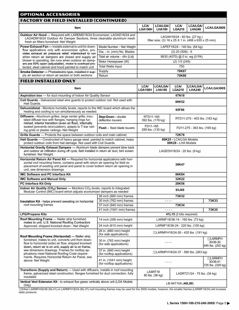
Outdoor Air Hood � Required with LAREMD18/24 Economizer, LAOAD18/24 andLAOADM18/24 Outdoor Air Damper Sections, three cleanable aluminum meshfresh air filters furnished− Net Weight
LAOAH18/24 − 60 lbs. (27 kg.)filter size: (3) 16 x 25 X 1 in. (406 x 635 x 25 mm)
Power Exhaust Fan � Installs external to unit for down�fl li ti l ith i ti
Model Number − Net Weight LAPEF18/24 − 140 lbs. (64 kg)flow applications only with economizer option, pro�vides exhaust air pressure relief, interlocked to run
Dia. − in. (mm) No. Blades (2) 20 (508) − 5vides exhaust air pressure relief, interlocked to runwhen return air dampers are closed and supply airbl i i f h d i d
Total air volume − cfm (L/s) 8630 (4070) @ 0 in. wg (0 PA)when return air dampers are closed and supply airblower is operating, fan runs when outdoor air damp�ers are 50% open (adjustable) motor is overload pro�
Motor Horsepower (W) (2) 1/3 (249)ers are 50% open (adjustable), motor is overload pro�tected, steel cabinet and hood painted to match unit Total Watts Input 750
Smoke Detector � Photoelectric type, installed in sup� Supply 70K87Smoke Detector � Photoelectric type, installed in sup�ply air section or return air section or both sections Return 70K86
FIELD INSTALLED ONLY
ItemLCA/
LGA156HLCA/LGA/LHA180
LCA/LGA210
LCA/LGA/LHA240
LCA/LGA300S
Aspiration box � for duct mounting of Indoor Air Quality Sensor 47N18
Coil Guards − Galvanized steel wire guards to protect outdoor coil. Not used withHail Guards.
88K52
Dehumidistat − Monitors humidity levels, reports to the IMC board which allows theheating and cooling to run simultaneously as needed.
65F86
Diffusers − Aluminum grilles, large center grille, insu�lated diffuser box with flanges, hanging rings fur�nished interior transition (even air flow) internally
Step�Down − doubledeflection louvers
RTD11−185392 lbs. (178 kg)
RTD11−275 − 403 lbs. (183 kg)
nished, interior transition (even air flow), internallysealed (prevents recirculation), adapts to T�bar ceil�ing grids or plaster ceilings− Net Weight
Flush − fixed blade louversFD11−185
289 lbs. (135 kg)FD11−275 − 363 lbs. (165 kg)
Grille Guards � Protects the space between outdoor coils and main cabinet. 72K78
Hail Guards � Constructed of heavy gauge steel, painted to match cabinet, helpsprotect outdoor coils from hail damage. Not used with Coil Guards.
88K25 − LCA/LGA Models88K28 − LHA Models
Horizontal Gravity Exhaust Dampers � Aluminum blade dampers prevent blow backand outdoor air infiltration during off cycle, field installed in return air duct, bird screenfurnished− Net Weight
LAGEDH18/24 − 20 lbs. (9 kg)
Horizontal Return Air Panel Kit � Required for horizontal applications with hori�zontal roof mounting frame, contains panel with return air opening for field re�placement of existing unit panel and panel to cover bottom return air opening inunit, see dimension drawings
38K47
IMC Software and PC Interface Kit 86K84
IMC Software and Manual Only 32K22
PC Interface Kit Only 28K56
Indoor Air Quality (CO2) Sensor � Monitors CO2 levels, reports to IntegratedModular Control (IMC) board which adjusts economizer dampers as needed
93J69
26 inch (660 mm) frames 73K32
Insulation Kit − helps prevent sweating on horizontal 30 inch (762 mm) frames − − − − 73K33Insulation Kit − helps prevent sweating on horizontalroof mounting frames 37 inch (940 mm) frames 73K34g
41 inch (1041 mm) frames − − − − 73K35
LPG/Propane Kits 41L15 (2 kits required)
Roof Mounting Frame � Nailer strip furnished,mates to unit U S National Roofing Contractors
14 inch (356 mm) height LARMF18/36�14 − 160 lbs. (73 kg)mates to unit, U.S. National Roofing ContractorsApproved, shipped knocked down − Net Weight 24 inch (610 mm) height LARMF18/36�24 − 220 lbs. (100 kg)
Roof Mounting Frame (Horizontal) � Nailer strip
26 in. (660 mm) height(for slab applications)
�LARMFH18/24�26 − 420 lbs. (191 kg)
Roof Mounting Frame (Horizontal) � Nailer stripfurnished, mates to unit, converts unit from down�flow to horizontal (side) air flow, shipped knockeddown, return air is on unit, supply air is on frame,
30 in. (762 mm) height(for slab applications)
− − − −�LARMFH30/36�30
445 lbs. (202 kg)down, return air is on unit, supply air is on frame,see dimension drawings. Frames for rooftop ap�plications meet National Roofing Code require�
t R i H i t l R t Ai P l
37 in. (940 mm) height(for rooftop applications)
�LARMFH18/24�37 − 580 lbs. (263 kg)p g qments. Requires Horizontal Return Air Panel, seeabove− Net Weight 41 in. (1041 mm) height
(for rooftop applications)− − − −
�LARMFH30/36�41
725 lbs. (329 kg)
Transitions (Supply and Return) � Used with diffusers, installs in roof mountingframe, galvanized steel construction, flanges furnished for duct connection, fullyinsulated
LASRT1880 lbs. (36 kg)
LASRT21/24 − 75 lbs. (34 kg)
Vertical Vent Extension Kit − to exhaust flue gases vertically above unit (LGA ModelsOnly)
LB−94710A (40L80)
�Either LARMFH30/36−30(−41) or LARMFH18/24−26(−37) roof mounting frames may be used for the 300S models, however, the smaller frames (LARMF18/24) will increasestatic pressure.
L Series 156H−180−210−240−300S/ Page 5 �
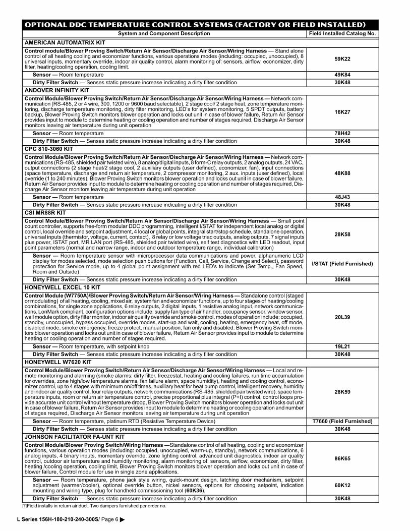
OPTIONAL DDC TEMPERATURE CONTROL SYSTEMS (Factory or Field Installed)System and Component Description Field Installed Catalog No.
AMERICAN AUTOMATRIX KIT
Control module/Blower Proving Switch/Return Air Sensor/Discharge Air Sensor/Wiring Harness � Stand alonecontrol of all heating cooling and economizer functions, various operations modes (including: occupied, unoccupied), 8universal inputs, momentary override, indoor air quality control, alarm monitoring of: sensors, airflow, economizer, dirtyfilter, heating/cooling operation, cooling limit.
59K22
Sensor � Room temperature 49K84
Dirty Filter Switch � Senses static pressure increase indicating a dirty filter condition 30K48
ANDOVER INFINITY KIT
Control Module/Blower Proving Switch/Return Air Sensor/Discharge Air Sensor/Wiring Harness � Network com�munication (RS−485, 2 or 4 wire, 300, 1200 or 9600 baud selectable), 2 stage cool/ 2 stage heat, zone temperature moni�toring, discharge temperature monitoring, dirty filter monitoring, LED’s for system monitoring, 5 SPDT outputs, batterybackup, Blower Proving Switch monitors blower operation and locks out unit in case of blower failure, Return Air Sensorprovides input to module to determine heating or cooling operation and number of stages required, Discharge Air Sensormonitors leaving air temperature during unit operation
16K27
Sensor � Room temperature 78H42
Dirty Filter Switch � Senses static pressure increase indicating a dirty filter condition 30K48
CPC 810−3060 KIT
Control Module/Blower Proving Switch/Return Air Sensor/Discharge Air Sensor/Wiring Harness � Network com�munications (RS−485, shielded pair twisted wire), 8 analog/digital inputs, 8 form−C relay outputs, 2 analog outputs, 24 VAC,output connections (2 stage heat/2 stage cool, 2 auxiliary outputs (user defined), economizer, fan), input connections(space temperature, discharge and return air temperature, 2 compressor monitoring, 2 aux. inputs (user defined), localoverride (1 to 240 minutes), Blower Proving Switch monitors blower operation and locks out unit in case of blower failure,Return Air Sensor provides input to module to determine heating or cooling operation and number of stages required, Dis�charge Air Sensor monitors leaving air temperature during unit operation
48K88
Sensor � Room temperature 48J43
Dirty Filter Switch � Senses static pressure increase indicating a dirty filter condition 30K48
CSI MR88R KIT
Control Module/Blower Proving Switch/Return Air Sensor/Discharge Air Sensor/Wiring Harness � Small pointcount controller, supports free�form modular DDC programming, intelligent I/STAT for independent local analog or digitalcontrol, local override and setpoint adjustment, 4 local or global points, integral start/stop schedule, standalone operation,universal inputs (thermistor, voltage, current, contact), 8 relay or low voltage triac outputs, analog outputs, 7 signal inputsplus power, ISTAT port, MR LAN port (RS−485, shielded pair twisted wire), self test diagnostics with LED readout, inputpoint parameters (normal and narrow range, indoor and outdoor temperature range, individual calibration)
28K58
Sensor � Room temperature sensor with microprocessor data communications and power, alphanumeric LCDdisplay for modes selected, mode selection push buttons for (Function, Call, Service, Change and Select), passwordprotection for Service mode, up to 4 global point assignment with red LED’s to indicate (Set Temp., Fan Speed,Room and Outside)
I/STAT (Field Furnished)
Dirty Filter Switch � Senses static pressure increase indicating a dirty filter condition 30K48
HONEYWELL EXCEL 10 KIT
Control Module (W7750A)/Blower Proving Switch/Return Air Sensor/Wiring Harness � Standalone control (stagedor modulating) of all heating, cooling, mixed air, system fan and economizer functions, up to four stages of heating/coolingcombinations, for single zone applications, 6 relay outputs, 2 digital inputs, 1 resistive analog input, network communica�tions, LonMark compliant, configuration options include: supply fan type of air handler, occupancy sensor, window sensor,wall module option, dirty filter monitor, indoor air quality override and smoke control. modes of operation include: occupied,standby, unoccupied, bypass occupied, override modes, start−up and wait, cooling, heating, emergency heat, off mode,disabled mode, smoke emergency, freeze protect, manual position, fan only and disabled. Blower Proving Switch moni�tors blower operation and locks out unit in case of blower failure, Return Air Sensor provides input to module to determineheating or cooling operation and number of stages required.
20L39
Sensor � Room temperature, with setpoint knob 19L21
Dirty Filter Switch � Senses static pressure increase indicating a dirty filter condition 30K48
HONEYWELL W7620 KIT
Control Module/Blower Proving Switch/Return Air Sensor/Discharge Air Sensor/Wiring Harness � Local and re�mote monitoring and alarming (smoke alarms, dirty filter, freezestat, heating and cooling failures, run time accumulationfor overrides, zone high/low temperature alarms, fan failure alarm, space humidity), heating and cooling control, econo�mizer control, up to 4 stages with minimum on/off times, auxiliary heat for heat pump control, intelligent recovery, humidityand indoor air quality control, four relay outputs, network communications (RS−485, shielded pair twisted wire), space tem�perature inputs, room or return air temperature control, precise proportional plus integral (P+I) control, control loops pro�vide accurate unit control without temperature droop, Blower Proving Switch monitors blower operation and locks out unitin case of blower failure, Return Air Sensor provides input to module to determine heating or cooling operation and numberof stages required, Discharge Air Sensor monitors leaving air temperature during unit operation
28K59
Sensor � Room temperature, platinum RTD (Resistive Temperature Device) T7660 (Field Furnished)
Dirty Filter Switch � Senses static pressure increase indicating a dirty filter condition 30K48
JOHNSON FACILITATOR FA−UNT KIT
Control Module/Blower Proving Switch/Wiring Harness �Standalone control of all heating, cooling and economizerfunctions, various operation modes (including: occupied, unoccupied, warm�up, standby), network communications, 6analog inputs, 4 binary inputs, momentary override, zone lighting control, advanced unit diagnostics, indoor air qualitycontrol, outdoor air temperature and humidity monitoring, alarm monitoring of: sensors, airflow, economizer, dirty filter,heating /cooling operation, cooling limit, Blower Proving Switch monitors blower operation and locks out unit in case ofblower failure, Control module for use in single zone applications.
86K65
Sensor � Room temperature, phone jack style wiring, quick−mount design, latching door mechanism, setpointadjustment (warmer/cooler), optional override button, nickel sensors, options for choosing setpoint, indicationmounting and wiring type, plug for handheld commissioning tool (60K36).
60K12
Dirty Filter Switch � Senses static pressure increase indicating a dirty filter condition 30K48
�Field installs in return air duct. Two dampers furnished per order no.
L Series 156H−180−210−240−300S/ Page 6 �
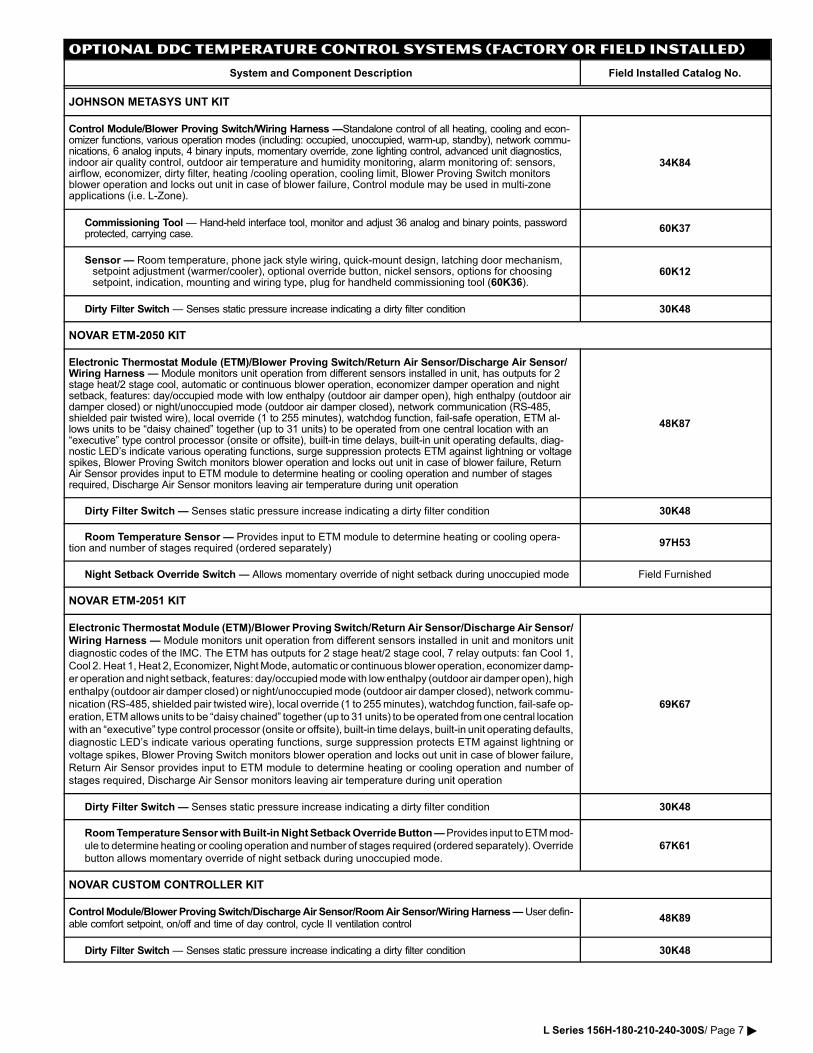
OPTIONAL DDC TEMPERATURE CONTROL SYSTEMS (Factory or Field Installed)
System and Component Description Field Installed Catalog No.
JOHNSON METASYS UNT KIT
Control Module/Blower Proving Switch/Wiring Harness �Standalone control of all heating, cooling and econ�omizer functions, various operation modes (including: occupied, unoccupied, warm�up, standby), network commu�nications, 6 analog inputs, 4 binary inputs, momentary override, zone lighting control, advanced unit diagnostics,indoor air quality control, outdoor air temperature and humidity monitoring, alarm monitoring of: sensors,airflow, economizer, dirty filter, heating /cooling operation, cooling limit, Blower Proving Switch monitorsblower operation and locks out unit in case of blower failure, Control module may be used in multi−zoneapplications (i.e. L−Zone).
34K84
Commissioning Tool � Hand−held interface tool, monitor and adjust 36 analog and binary points, password protected, carrying case.
60K37
Sensor � Room temperature, phone jack style wiring, quick−mount design, latching door mechanism,setpoint adjustment (warmer/cooler), optional override button, nickel sensors, options for choosingsetpoint, indication, mounting and wiring type, plug for handheld commissioning tool (60K36).
60K12
Dirty Filter Switch � Senses static pressure increase indicating a dirty filter condition 30K48
NOVAR ETM−2050 KIT
Electronic Thermostat Module (ETM)/Blower Proving Switch/Return Air Sensor/Discharge Air Sensor/Wiring Harness � Module monitors unit operation from different sensors installed in unit, has outputs for 2stage heat/2 stage cool, automatic or continuous blower operation, economizer damper operation and nightsetback, features: day/occupied mode with low enthalpy (outdoor air damper open), high enthalpy (outdoor airdamper closed) or night/unoccupied mode (outdoor air damper closed), network communication (RS−485,shielded pair twisted wire), local override (1 to 255 minutes), watchdog function, fail−safe operation, ETM al�lows units to be �daisy chained" together (up to 31 units) to be operated from one central location with an�executive" type control processor (onsite or offsite), built�in time delays, built�in unit operating defaults, diag�nostic LED’s indicate various operating functions, surge suppression protects ETM against lightning or voltagespikes, Blower Proving Switch monitors blower operation and locks out unit in case of blower failure, ReturnAir Sensor provides input to ETM module to determine heating or cooling operation and number of stagesrequired, Discharge Air Sensor monitors leaving air temperature during unit operation
48K87
Dirty Filter Switch � Senses static pressure increase indicating a dirty filter condition 30K48
Room Temperature Sensor � Provides input to ETM module to determine heating or cooling opera�tion and number of stages required (ordered separately)
97H53
Night Setback Override Switch � Allows momentary override of night setback during unoccupied mode Field Furnished
NOVAR ETM−2051 KIT
Electronic Thermostat Module (ETM)/Blower Proving Switch/Return Air Sensor/Discharge Air Sensor/
Wiring Harness � Module monitors unit operation from different sensors installed in unit and monitors unit
diagnostic codes of the IMC. The ETM has outputs for 2 stage heat/2 stage cool, 7 relay outputs: fan Cool 1,
Cool 2. Heat 1, Heat 2, Economizer, Night Mode, automatic or continuous blower operation, economizer damp�
er operation and night setback, features: day/occupied mode with low enthalpy (outdoor air damper open), high
enthalpy (outdoor air damper closed) or night/unoccupied mode (outdoor air damper closed), network commu�
nication (RS−485, shielded pair twisted wire), local override (1 to 255 minutes), watchdog function, fail−safe op�
eration, ETM allows units to be �daisy chained" together (up to 31 units) to be operated from one central location
with an �executive" type control processor (onsite or offsite), built�in time delays, built�in unit operating defaults,
diagnostic LED’s indicate various operating functions, surge suppression protects ETM against lightning or
voltage spikes, Blower Proving Switch monitors blower operation and locks out unit in case of blower failure,
Return Air Sensor provides input to ETM module to determine heating or cooling operation and number of
stages required, Discharge Air Sensor monitors leaving air temperature during unit operation
69K67
Dirty Filter Switch � Senses static pressure increase indicating a dirty filter condition 30K48
Room Temperature Sensor with Built−in Night Setback Override Button � Provides input to ETM mod�
ule to determine heating or cooling operation and number of stages required (ordered separately). Override
button allows momentary override of night setback during unoccupied mode.
67K61
NOVAR CUSTOM CONTROLLER KIT
Control Module/Blower Proving Switch/Discharge Air Sensor/Room Air Sensor/Wiring Harness � User defin�able comfort setpoint, on/off and time of day control, cycle II ventilation control
48K89
Dirty Filter Switch � Senses static pressure increase indicating a dirty filter condition 30K48
L Series 156H−180−210−240−300S/ Page 7 �
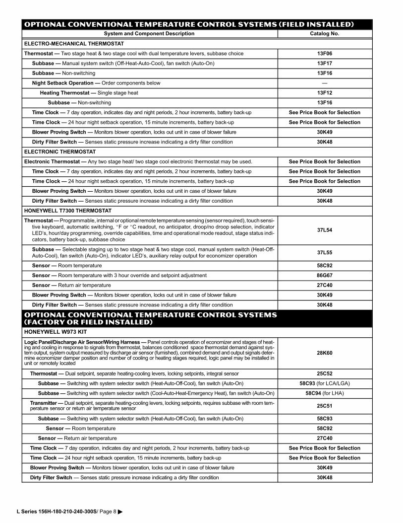
OPTIONAL CONVENTIONAL TEMPERATURE CONTROL SYSTEMS (Field Installed)
System and Component Description Catalog No.
ELECTRO�MECHANICAL THERMOSTAT
Thermostat � Two stage heat & two stage cool with dual temperature levers, subbase choice 13F06
Subbase � Manual system switch (Off�Heat�Auto�Cool), fan switch (Auto�On) 13F17
Subbase � Non�switching 13F16
Night Setback Operation � Order components below �
Heating Thermostat � Single stage heat 13F12
Subbase � Non�switching 13F16
Time Clock � 7 day operation, indicates day and night periods, 2 hour increments, battery back�up See Price Book for Selection
Time Clock � 24 hour night setback operation, 15 minute increments, battery back�up See Price Book for Selection
Blower Proving Switch � Monitors blower operation, locks out unit in case of blower failure 30K49
Dirty Filter Switch � Senses static pressure increase indicating a dirty filter condition 30K48
ELECTRONIC THERMOSTAT
Electronic Thermostat � Any two stage heat/ two stage cool electronic thermostat may be used. See Price Book for Selection
Time Clock � 7 day operation, indicates day and night periods, 2 hour increments, battery back�up See Price Book for Selection
Time Clock � 24 hour night setback operation, 15 minute increments, battery back�up See Price Book for Selection
Blower Proving Switch � Monitors blower operation, locks out unit in case of blower failure 30K49
Dirty Filter Switch � Senses static pressure increase indicating a dirty filter condition 30K48
HONEYWELL T7300 THERMOSTAT
Thermostat � Programmable, internal or optional remote temperature sensing (sensor required), touch sensi�
tive keyboard, automatic switching, �F or �C readout, no anticipator, droop/no droop selection, indicatorLED’s, hour/day programming, override capabilities, time and operational mode readout, stage status indi�
cators, battery back�up, subbase choice
37L54
Subbase � Selectable staging up to two stage heat & two stage cool, manual system switch (Heat�Off�
Auto�Cool), fan switch (Auto�On), indicator LED’s, auxiliary relay output for economizer operation37L55
Sensor � Room temperature 58C92
Sensor � Room temperature with 3 hour override and setpoint adjustment 86G67
Sensor � Return air temperature 27C40
Blower Proving Switch � Monitors blower operation, locks out unit in case of blower failure 30K49
Dirty Filter Switch � Senses static pressure increase indicating a dirty filter condition 30K48
OPTIONAL CONVENTIONAL TEMPERATURE CONTROL SYSTEMS(FACTORY OR Field Installed)
HONEYWELL W973 KIT
Logic Panel/Discharge Air Sensor/Wiring Harness � Panel controls operation of economizer and stages of heat�ing and cooling in response to signals from thermostat, balances conditioned space thermostat demand against sys�tem output, system output measured by discharge air sensor (furnished), combined demand and output signals deter�mine economizer damper position and number of cooling or heating stages required, logic panel may be installed inunit or remotely located
28K60
Thermostat � Dual setpoint, separate heating�cooling levers, locking setpoints, integral sensor 25C52
Subbase � Switching with system selector switch (Heat�Auto�Off�Cool), fan switch (Auto�On) 58C93 (for LCA/LGA)
Subbase � Switching with system selector switch (Cool�Auto�Heat�Emergency Heat), fan switch (Auto�On) 58C94 (for LHA)
Transmitter � Dual setpoint, separate heating�cooling levers, locking setpoints, requires subbase with room tem�perature sensor or return air temperature sensor 25C51
Subbase � Switching with system selector switch (Heat�Auto�Off�Cool), fan switch (Auto�On) 58C93
Sensor � Room temperature 58C92
Sensor � Return air temperature 27C40
Time Clock � 7 day operation, indicates day and night periods, 2 hour increments, battery back�up See Price Book for Selection
Time Clock � 24 hour night setback operation, 15 minute increments, battery back�up See Price Book for Selection
Blower Proving Switch � Monitors blower operation, locks out unit in case of blower failure 30K49
Dirty Filter Switch � Senses static pressure increase indicating a dirty filter condition 30K48
L Series 156H−180−210−240−300S/ Page 8 �
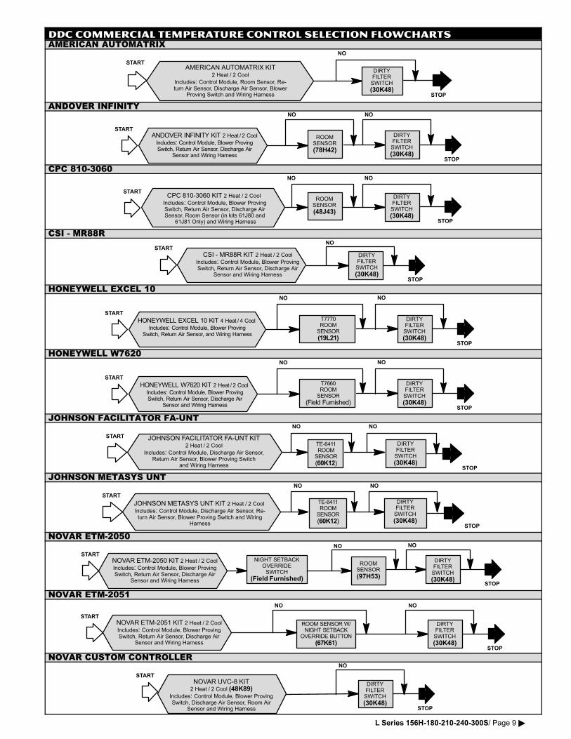
DDC COMMERCIAL TEMPERATURE CONTROL SELECTION FLOWCHARTSAMERICAN AUTOMATRIX
AMERICAN AUTOMATRIX KIT2 Heat�/�2 Cool
Includes: Control Module, Room Sensor, Re�turn Air Sensor, Discharge Air Sensor, Blower
Proving Switch and Wiring Harness
START
STOP
DIRTYFILTERSWITCH
(30K48)
NO
ANDOVER INFINITY
STOP
ROOMSENSOR
(78H42)
NO
DIRTYFILTERSWITCH
(30K48)
NO
ANDOVER INFINITY KIT 2 Heat�/�2 CoolIncludes: Control Module, Blower ProvingSwitch, Return Air Sensor, Discharge Air
Sensor and Wiring Harness
START
CPC 810−3060
STOP
ROOMSENSOR
(48J43)
NO
DIRTYFILTERSWITCH
(30K48)
NO
CPC 810�3060 KIT 2 Heat�/�2 Cool Includes: Control Module, Blower ProvingSwitch, Return Air Sensor, Discharge AirSensor, Room Sensor (in kits 61J80 and
61J81 Only) and Wiring Harness
START
CSI − MR88R
STOP
DIRTYFILTERSWITCH
(30K48)
NO
CSI − MR88R KIT 2 Heat�/�2 CoolIncludes: Control Module, Blower ProvingSwitch, Return Air Sensor, Discharge Air
Sensor and Wiring Harness
START
HONEYWELL EXCEL 10
HONEYWELL EXCEL 10 KIT 4 Heat�/�4 Cool Includes: Control Module, Blower Proving
Switch, Return Air Sensor, and Wiring Harness
STOP
T7770ROOM
SENSOR
(19L21)
NO
DIRTYFILTERSWITCH
(30K48)
NO
START
HONEYWELL W7620
STOP
T7660ROOM
SENSOR
(Field Furnished)
NO
DIRTYFILTERSWITCH
(30K48)
NO
HONEYWELL W7620 KIT 2 Heat�/�2 Cool Includes: Control Module, Blower ProvingSwitch, Return Air Sensor, Discharge Air
Sensor and Wiring Harness
START
JOHNSON FACILITATOR FA−UNTNO
START
STOP
TE�6411ROOM
SENSOR
(60K12)
DIRTYFILTERSWITCH
(30K48)
NO
JOHNSON FACILITATOR FA−UNT KIT2 Heat�/�2 Cool
Includes: Control Module, Discharge Air Sensor,Return Air Sensor, Blower Proving Switch
and Wiring Harness
JOHNSON METASYS UNTNO
JOHNSON METASYS UNT KIT 2 Heat�/�2 Cool Includes: Control Module, Discharge Air Sensor, Re�turn Air Sensor, Blower Proving Switch and Wiring
Harness
START
NO
STOP
TE�6411ROOM
SENSOR
(60K12)
DIRTYFILTERSWITCH
(30K48)
NOVAR ETM−2050
STOP
START
ROOMSENSOR
(97H53)
NO
DIRTYFILTERSWITCH
(30K48)
NO
NIGHT SETBACKOVERRIDESWITCH
(Field Furnished)
NOVAR ETM�2050 KIT 2 Heat�/�2 CoolIncludes: Control Module, Blower ProvingSwitch, Return Air Sensor, Discharge Air
Sensor and Wiring Harness
NOVAR ETM−2051
STARTNOVAR ETM�2051 KIT 2 Heat�/�2 CoolIncludes: Control Module, Blower ProvingSwitch, Return Air Sensor, Discharge Air
Sensor and Wiring Harness
NO
STOP
ROOM SENSOR W/NIGHT SETBACK
OVERRIDE BUTTON
(67K61)
DIRTYFILTERSWITCH
(30K48)
NO
NOVAR CUSTOM CONTROLLER
START
STOP
DIRTYFILTERSWITCH
(30K48)
NO
NOVAR UVC�8 KIT2 Heat�/�2 Cool (48K89)
Includes: Control Module, Blower ProvingSwitch, Discharge Air Sensor, Room Air
Sensor and Wiring Harness
L Series 156H−180−210−240−300S/ Page 9 �
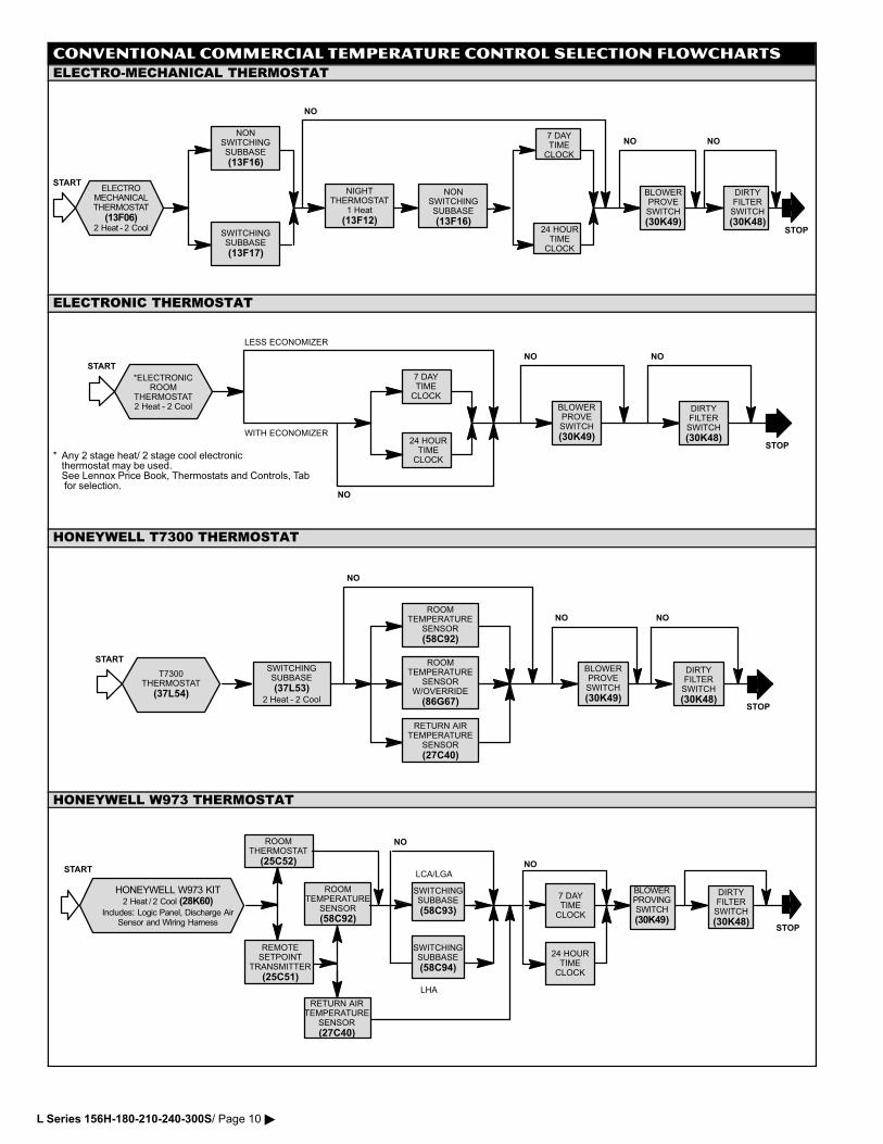
CONVENTIONAL COMMERCIAL TEMPERATURE CONTROL SELECTION FLOWCHARTS
ELECTRO−MECHANICAL THERMOSTAT
24 HOURTIME
CLOCK
NO
STOP
ELECTROMECHANICALTHERMOSTAT
(13F06)2 Heat�−�2 Cool
START
NONSWITCHINGSUBBASE
(13F16)
SWITCHINGSUBBASE
(13F17)
NIGHTTHERMOSTAT
1 Heat
(13F12)
NONSWITCHINGSUBBASE
(13F16)
7 DAYTIME
CLOCK
NO NO
BLOWERPROVESWITCH
(30K49)
DIRTYFILTERSWITCH
(30K48)
ELECTRONIC THERMOSTAT
STOP
*ELECTRONICROOM
THERMOSTAT2 Heat�−�2 Cool
START
24 HOURTIME
CLOCK
7 DAYTIME
CLOCK
NO NO
BLOWERPROVESWITCH
(30K49)
DIRTYFILTERSWITCH
(30K48)
LESS ECONOMIZER
WITH ECONOMIZER
NO
* Any 2 stage heat/ 2 stage cool electronicthermostat may be used.See Lennox Price Book, Thermostats and Controls, Tab for selection.
HONEYWELL T7300 THERMOSTAT
ROOMTEMPERATURE
SENSORW/OVERRIDE
(86G67)
NO
STOP
T7300THERMOSTAT
(37L54)
STARTSWITCHINGSUBBASE
(37L53)2 Heat�−�2 Cool
NO NO
BLOWERPROVESWITCH
(30K49)
DIRTYFILTERSWITCH
(30K48)
ROOMTEMPERATURE
SENSOR
(58C92)
RETURN AIRTEMPERATURE
SENSOR
(27C40)
HONEYWELL W973 THERMOSTAT
REMOTESETPOINT
TRANSMITTER
(25C51)
RETURN AIRTEMPERATURE
SENSOR
(27C40)
24 HOURTIME
CLOCK
DIRTYFILTERSWITCH
(30K48)
ROOMTHERMOSTAT
(25C52)
HONEYWELL W973 KIT2 Heat�/�2 Cool (28K60)
Includes: Logic Panel, Discharge AirSensor and Wiring Harness
7 DAYTIME
CLOCK
NO
ROOMTEMPERATURE
SENSOR
(58C92)
SWITCHINGSUBBASE
(58C93)
NO
STOP
SWITCHINGSUBBASE
(58C94)
LCA/LGA
LHA
START
BLOWERPROVINGSWITCH
(30K49)
L Series 156H−180−210−240−300S/ Page 10 �
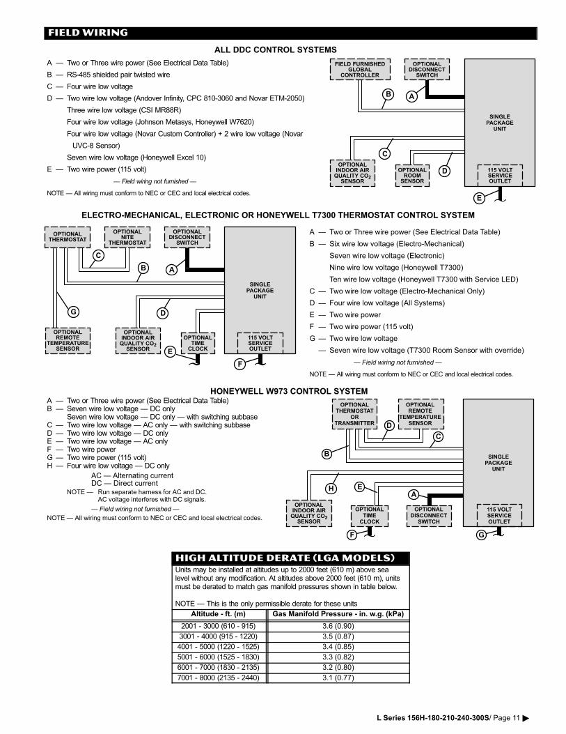
FIELD WIRING
OPTIONALTIME
CLOCK
OPTIONALTHERMOSTAT
ORTRANSMITTER
OPTIONALREMOTE
TEMPERATURESENSOR
OPTIONALDISCONNECT
SWITCH
D
B
E
F
C
A
HONEYWELL W973 CONTROL SYSTEMA � Two or Three wire power (See Electrical Data Table)B � Seven wire low voltage � DC only
Seven wire low voltage � DC only � with switching subbaseC � Two wire low voltage � AC only � with switching subbaseD � Two wire low voltage � DC onlyE � Two wire low voltage � AC onlyF � Two wire powerG � Two wire power (115 volt)H � Four wire low voltage � DC only
AC � Alternating currentDC � Direct current
NOTE � Run separate harness for AC and DC.AC voltage interferes with DC signals.
� Field wiring not furnished �
NOTE � All wiring must conform to NEC or CEC and local electrical codes.
SINGLEPACKAGE
UNIT
115 VOLTSERVICEOUTLET
G
OPTIONALINDOOR AIRQUALITY CO2
SENSOR
H
ELECTRO�MECHANICAL, ELECTRONIC OR HONEYWELL T7300 THERMOSTAT CONTROL SYSTEM
OPTIONALTHERMOSTAT
OPTIONALNITE
THERMOSTAT
OPTIONALDISCONNECT
SWITCH
OPTIONALTIME
CLOCK
OPTIONALINDOOR AIRQUALITY CO2
SENSOR
115 VOLTSERVICEOUTLET
SINGLEPACKAGE
UNIT
A � Two or Three wire power (See Electrical Data Table)
B � Six wire low voltage (Electro�Mechanical)
Seven wire low voltage (Electronic)
Nine wire low voltage (Honeywell T7300)
Ten wire low voltage (Honeywell T7300 with Service LED)
C � Two wire low voltage (Electro�Mechanical Only)
D � Four wire low voltage (All Systems)
E � Two wire power
F � Two wire power (115 volt)
G � Two wire low voltage
� Seven wire low voltage (T7300 Room Sensor with override)
� Field wiring not furnished �
NOTE � All wiring must conform to NEC or CEC and local electrical codes.
AB
C
E
D
ALL DDC CONTROL SYSTEMS
FIELD FURNISHEDGLOBAL
CONTROLLER
OPTIONALDISCONNECT
SWITCH
OPTIONALROOM
SENSOR
115 VOLTSERVICEOUTLET
SINGLEPACKAGE
UNIT
AB
C
D
E
A � Two or Three wire power (See Electrical Data Table)
B � RS�485 shielded pair twisted wire
C � Four wire low voltage
D � Two wire low voltage (Andover Infinity, CPC 810�3060 and Novar ETM�2050)
Three wire low voltage (CSI MR88R)
Four wire low voltage (Johnson Metasys, Honeywell W7620)
Four wire low voltage (Novar Custom Controller) + 2 wire low voltage (Novar
UVC�8 Sensor)
Seven wire low voltage (Honeywell Excel 10)
E � Two wire power (115 volt)
� Field wiring not furnished �
NOTE � All wiring must conform to NEC or CEC and local electrical codes.
OPTIONALINDOOR AIRQUALITY CO2
SENSOR
F
OPTIONALREMOTE
TEMPERATURESENSOR
G
HIGH ALTITUDE DERATE (LGA MODELS)Units may be installed at altitudes up to 2000 feet (610 m) above sealevel without any modification. At altitudes above 2000 feet (610 m), unitsmust be derated to match gas manifold pressures shown in table below.
NOTE � This is the only permissible derate for these units
Altitude − ft. (m) Gas Manifold Pressure − in. w.g. (kPa)
2001 − 3000 (610 − 915) 3.6 (0.90)
3001 − 4000 (915 − 1220) 3.5 (0.87)
4001 − 5000 (1220 − 1525) 3.4 (0.85)
5001 − 6000 (1525 − 1830) 3.3 (0.82)
6001 − 7000 (1830 − 2135) 3.2 (0.80)
7001 − 8000 (2135 − 2440) 3.1 (0.77)
L Series 156H−180−210−240−300S/ Page 11 �
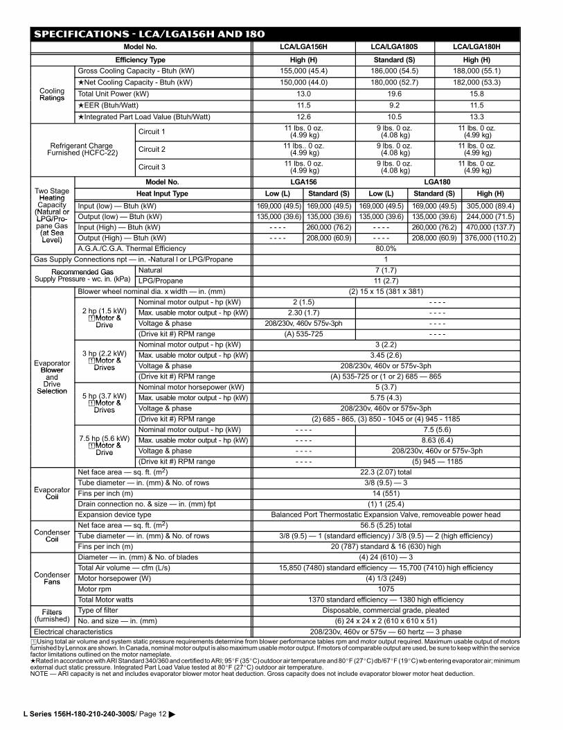
SPECIFICATIONS − LCA/LGA156H and 180
Model No. LCA/LGA156H LCA/LGA180S LCA/LGA180H
Efficiency Type High (H) Standard (S) High (H)
Gross Cooling Capacity − Btuh (kW) 155,000 (45.4) 186,000 (54.5) 188,000 (55.1)
C liNet Cooling Capacity − Btuh (kW) 150,000 (44.0) 180,000 (52.7) 182,000 (53.3)
CoolingRatings
Total Unit Power (kW) 13.0 19.6 15.8Ratings
EER (Btuh/Watt) 11.5 9.2 11.5
Integrated Part Load Value (Btuh/Watt) 12.6 10.5 13.3
Circuit 111 lbs. 0 oz. (4.99 kg)
9 lbs. 0 oz. (4.08 kg)
11 lbs. 0 oz. (4.99 kg)
Refrigerant Charge Furnished (HCFC�22) Circuit 2
11 lbs.. 0 oz. (4.99 kg)
9 lbs. 0 oz. (4.08 kg)
11 lbs. 0 oz. (4.99 kg)( )
Circuit 311 lbs. 0 oz. (4.99 kg)
9 lbs. 0 oz. (4.08 kg)
11 lbs. 0 oz. (4.99 kg)
Model No. LGA156 LGA180
Two StageHeating
Heat Input Type Low (L) Standard (S) Low (L) Standard (S) High (H)HeatingCapacity(Natural or
Input (low) � Btuh (kW) 169,000 (49.5) 169,000 (49.5) 169,000 (49.5) 169,000 (49.5) 305,000 (89.4)p y(Natural orLPG/Pro� Output (low) � Btuh (kW) 135,000 (39.6) 135,000 (39.6) 135,000 (39.6) 135,000 (39.6) 244,000 (71.5)LPG/Pro�pane Gas(at Sea
Input (High) � Btuh (kW) − − − − 260,000 (76.2) − − − − 260,000 (76.2) 470,000 (137.7)(at SeaLevel) Output (High) � Btuh (kW) − − − − 208,000 (60.9) − − − − 208,000 (60.9) 376,000 (110.2)Level)
A.G.A./C.G.A. Thermal Efficiency 80.0%
Gas Supply Connections npt � in. −Natural l or LPG/Propane 1
Recommended Gas Natural 7 (1.7)Recommended GasSupply Pressure − wc. in. (kPa) LPG/Propane 11 (2.7)
Blower�wheel�nominal�dia.�x�width���in.�(mm) (2) 15 x 15 (381 x 381)
Nominal motor output − hp (kW) 2 (1.5) − − − −
2 hp (1.5 kW)�Motor &
Max. usable motor output − hp (kW) 2.30 (1.7) − − − −�Motor &
Drive Voltage & phase 208/230v, 460v 575v�3ph − − − −Drive
(Drive kit #) RPM range (A) 535−725 − − − −
Nominal motor output − hp (kW) 3 (2.2)
E t
3 hp (2.2 kW)�Motor &
Max. usable motor output − hp (kW) 3.45 (2.6)EvaporatorBlower
�Motor &Drives Voltage & phase 208/230v, 460v or 575v�3ph
BlowerandD i
Drives
(Drive kit #) RPM range (A) 535−725 or (1 or 2) 685 � 865andDrive
SelectionNominal motor horsepower (kW) 5 (3.7)
Selection5 hp (3.7 kW)�Motor &
Max. usable motor output − hp (kW) 5.75 (4.3)�Motor &Drives Voltage & phase 208/230v, 460v or 575v�3phDrives
(Drive kit #) RPM range (2) 685 − 865, (3) 850 − 1045 or (4) 945 − 1185
Nominal motor output − hp (kW) − − − − 7.5 (5.6)
7.5 hp (5.6 kW)�Motor &
Max. usable motor output − hp (kW) − − − − 8.63 (6.4)�Motor &
Drive Voltage & phase − − − − 208/230v, 460v or 575v�3phDrive
(Drive kit #) RPM range − − − − (5) 945 � 1185
Net face area � sq. ft. (m2) 22.3 (2.07) total
EvaporatorTube diameter � in. (mm) & No. of rows 3/8 (9.5) � 3
EvaporatorCoil Fins per inch (m) 14 (551)Coil
Drain connection no. & size � in. (mm) fpt (1) 1 (25.4)
Expansion device type Balanced Port Thermostatic Expansion Valve, removeable power head
CondenserNet face area � sq. ft. (m2) 56.5 (5.25) total
CondenserCoil Tube diameter � in. (mm) & No. of rows 3/8 (9.5) � 1 (standard efficiency) / 3/8 (9.5) � 2 (high efficiency)Coil
Fins per inch (m) 20 (787) standard & 16 (630) high
Diameter � in. (mm) & No. of blades (4) 24 (610) � 3
CondenserTotal Air volume � cfm (L/s) 15,850 (7480) standard efficiency � 15,700 (7410) high efficiency
CondenserFans Motor horsepower (W) (4) 1/3 (249)Fans
Motor rpm 1075
Total Motor watts 1370 standard efficiency � 1380 high efficiency
Filters Type of filter Disposable, commercial grade, pleatedFilters(furnished) No. and size � in. (mm) (6) 24 x 24 x 2 (610 x 610 x 51)
Electrical characteristics 208/230v, 460v or 575v � 60 hertz � 3 phase
�Using total air volume and system static pressure requirements determine from blower performance tables rpm and motor output required. Maximum usable output of motorsfurnished by Lennox are shown. In Canada, nominal motor output is also maximum usable motor output. If motors of comparable output are used, be sure to keep within the servicefactor limitations outlined on the motor nameplate.Rated in accordance with ARI Standard 340/360 and certified to ARI; 95�F (35�C) outdoor air temperature and 80�F (27�C) db/67�F (19�C) wb entering evaporator air; minimumexternal duct static pressure. Integrated Part Load Value tested at 80�F (27�C) outdoor air temperature.NOTE � ARI capacity is net and includes evaporator blower motor heat deduction. Gross capacity does not include evaporator blower motor heat deduction.
L Series 156H−180−210−240−300S/ Page 12 �
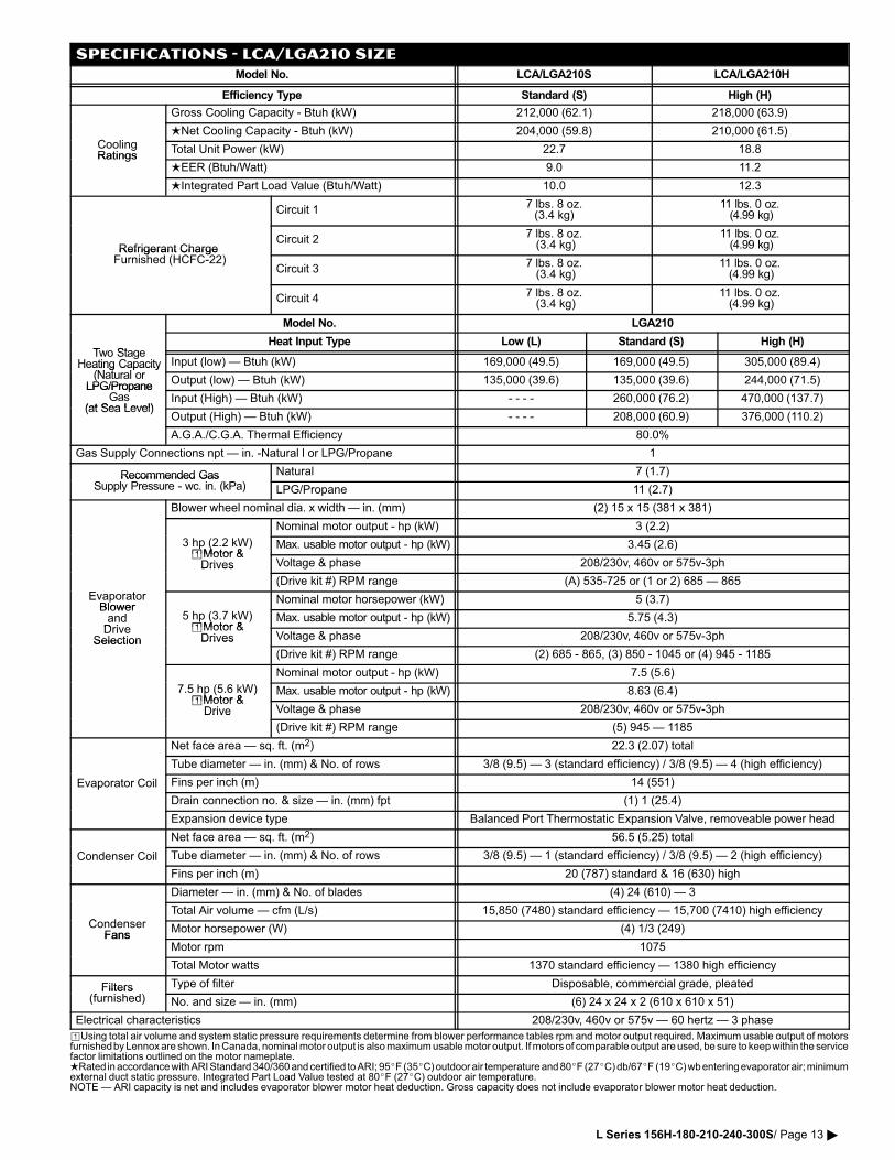
SPECIFICATIONS − LCA/LGA210 SIZE
Model No. LCA/LGA210S LCA/LGA210H
Efficiency Type Standard (S) High (H)
Gross Cooling Capacity − Btuh (kW) 212,000 (62.1) 218,000 (63.9)
C liNet Cooling Capacity − Btuh (kW) 204,000 (59.8) 210,000 (61.5)
CoolingRatings
Total Unit Power (kW) 22.7 18.8Ratings
EER (Btuh/Watt) 9.0 11.2
Integrated Part Load Value (Btuh/Watt) 10.0 12.3
Circuit 17 lbs. 8 oz.(3.4 kg)
11 lbs. 0 oz. (4.99 kg)
Refrigerant Charge Circuit 2
7 lbs. 8 oz. (3.4 kg)
11 lbs. 0 oz. (4.99 kg)Refrigerant Charge
Furnished (HCFC�22)Circuit 3
7 lbs. 8 oz. (3.4 kg)
11 lbs. 0 oz. (4.99 kg)
Circuit 47 lbs. 8 oz. (3.4 kg)
11 lbs. 0 oz. (4.99 kg)
Model No. LGA210
Two StageHeat Input Type Low (L) Standard (S) High (H)
Two StageHeating Capacity
(N t lInput (low) � Btuh (kW) 169,000 (49.5) 169,000 (49.5) 305,000 (89.4)Heating Capacity
(Natural orLPG/Propane
Output (low) � Btuh (kW) 135,000 (39.6) 135,000 (39.6) 244,000 (71.5)LPG/Propane
Gas(at Sea Level)
Input (High) � Btuh (kW) − − − − 260,000 (76.2) 470,000 (137.7)(at Sea Level)
Output (High) � Btuh (kW) − − − − 208,000 (60.9) 376,000 (110.2)
A.G.A./C.G.A. Thermal Efficiency 80.0%
Gas Supply Connections npt � in. −Natural l or LPG/Propane 1
Recommended Gas Natural 7 (1.7)Recommended GasSupply Pressure − wc. in. (kPa) LPG/Propane 11 (2.7)
Blower�wheel�nominal�dia.�x�width���in.�(mm) (2) 15 x 15 (381 x 381)
Nominal motor output − hp (kW) 3 (2.2)
3 hp (2.2 kW)�Motor &
Max. usable motor output − hp (kW) 3.45 (2.6)�Motor &Drives Voltage & phase 208/230v, 460v or 575v�3phDrives
(Drive kit #) RPM range (A) 535−725 or (1 or 2) 685 � 865
EvaporatorBlower
Nominal motor horsepower (kW) 5 (3.7)BlowerandDrive
5 hp (3.7 kW)�Motor &
Max. usable motor output − hp (kW) 5.75 (4.3)Drive
Selection�Motor &Drives Voltage & phase 208/230v, 460v or 575v�3phSelection Drives
(Drive kit #) RPM range (2) 685 − 865, (3) 850 − 1045 or (4) 945 − 1185
Nominal motor output − hp (kW) 7.5 (5.6)
7.5 hp (5.6 kW)�Motor &
Max. usable motor output − hp (kW) 8.63 (6.4)�Motor &
Drive Voltage & phase 208/230v, 460v or 575v�3phDrive
(Drive kit #) RPM range (5) 945 � 1185
Net face area � sq. ft. (m2) 22.3 (2.07) total
Tube diameter � in. (mm) & No. of rows 3/8 (9.5) � 3 (standard efficiency) / 3/8 (9.5) � 4 (high efficiency)
Evaporator Coil Fins per inch (m) 14 (551)p
Drain connection no. & size � in. (mm) fpt (1) 1 (25.4)
Expansion device type Balanced Port Thermostatic Expansion Valve, removeable power head
Net face area � sq. ft. (m2) 56.5 (5.25) total
Condenser Coil Tube diameter � in. (mm) & No. of rows 3/8 (9.5) � 1 (standard efficiency) / 3/8 (9.5) � 2 (high efficiency)
Fins per inch (m) 20 (787) standard & 16 (630) high
Diameter � in. (mm) & No. of blades (4) 24 (610) � 3
C dTotal Air volume � cfm (L/s) 15,850 (7480) standard efficiency � 15,700 (7410) high efficiency
CondenserFans
Motor horsepower (W) (4) 1/3 (249)Fans
Motor rpm 1075
Total Motor watts 1370 standard efficiency � 1380 high efficiency
Filters Type of filter Disposable, commercial grade, pleatedFilters(furnished) No. and size � in. (mm) (6) 24 x 24 x 2 (610 x 610 x 51)
Electrical characteristics 208/230v, 460v or 575v � 60 hertz � 3 phase
�Using total air volume and system static pressure requirements determine from blower performance tables rpm and motor output required. Maximum usable output of motorsfurnished by Lennox are shown. In Canada, nominal motor output is also maximum usable motor output. If motors of comparable output are used, be sure to keep within the servicefactor limitations outlined on the motor nameplate.Rated in accordance with ARI Standard 340/360 and certified to ARI; 95�F (35�C) outdoor air temperature and 80�F (27�C) db/67�F (19�C) wb entering evaporator air; minimumexternal duct static pressure. Integrated Part Load Value tested at 80�F (27�C) outdoor air temperature.NOTE � ARI capacity is net and includes evaporator blower motor heat deduction. Gross capacity does not include evaporator blower motor heat deduction.
L Series 156H−180−210−240−300S/ Page 13 �
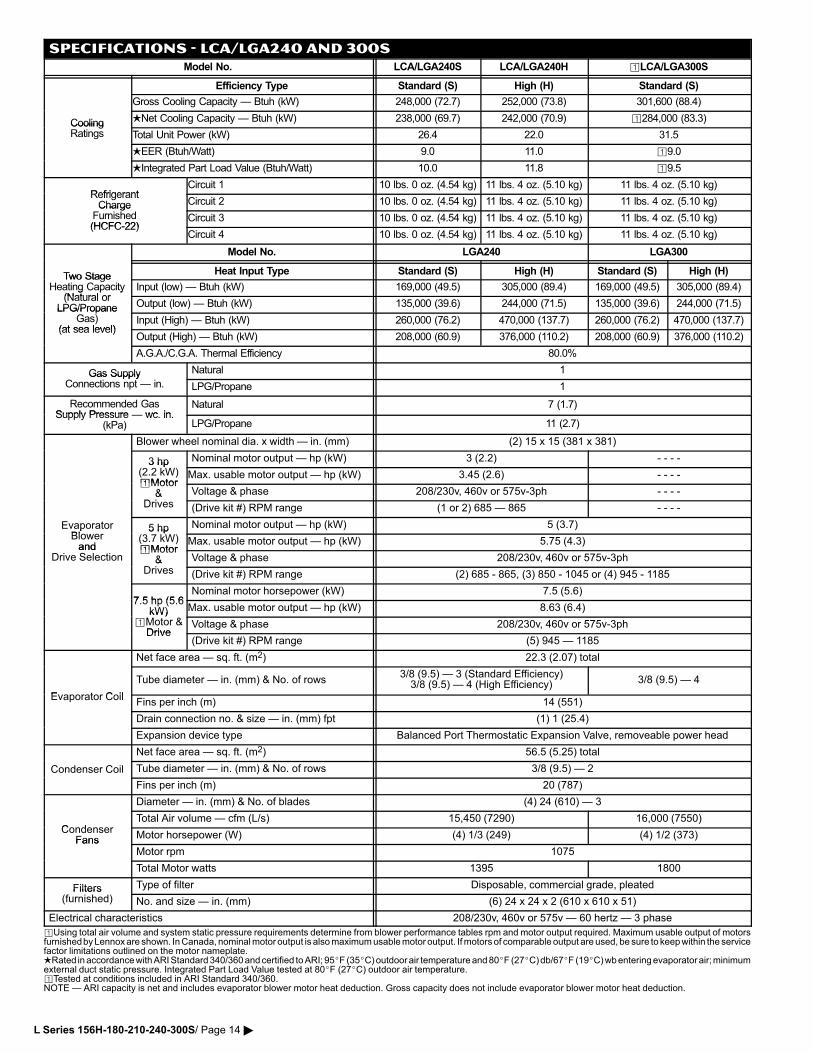
SPECIFICATIONS − LCA/LGA240 AND 300S
Model No. LCA/LGA240S LCA/LGA240H �LCA/LGA300S
Efficiency Type Standard (S) High (H) Standard (S)
Gross Cooling Capacity � Btuh (kW) 248,000 (72.7) 252,000 (73.8) 301,600 (88.4)
Cooling Net Cooling Capacity � Btuh (kW) 238,000 (69.7) 242,000 (70.9) �284,000 (83.3)CoolingRatings Total Unit Power (kW) 26.4 22.0 31.5
EER (Btuh/Watt) 9.0 11.0 �9.0
Integrated Part Load Value (Btuh/Watt) 10.0 11.8 �9.5
RefrigerantCircuit 1 10 lbs. 0 oz. (4.54 kg) 11 lbs. 4 oz. (5.10 kg) 11 lbs. 4 oz. (5.10 kg)
RefrigerantCharge Circuit 2 10 lbs. 0 oz. (4.54 kg) 11 lbs. 4 oz. (5.10 kg) 11 lbs. 4 oz. (5.10 kg)Charge
Furnished(HCFC�22)
Circuit 3 10 lbs. 0 oz. (4.54 kg) 11 lbs. 4 oz. (5.10 kg) 11 lbs. 4 oz. (5.10 kg)(HCFC�22)
Circuit 4 10 lbs. 0 oz. (4.54 kg) 11 lbs. 4 oz. (5.10 kg) 11 lbs. 4 oz. (5.10 kg)
Model No. LGA240 LGA300
Two StageHeat Input Type Standard (S) High (H) Standard (S) High (H)
Two StageHeating Capacity
(Natural orInput (low) � Btuh (kW) 169,000 (49.5) 305,000 (89.4) 169,000 (49.5) 305,000 (89.4)g p y
(Natural orLPG/Propane Output (low) � Btuh (kW) 135,000 (39.6) 244,000 (71.5) 135,000 (39.6) 244,000 (71.5)LPG/Propane
Gas)(at sea level)
Input (High) � Btuh (kW) 260,000 (76.2) 470,000 (137.7) 260,000 (76.2) 470,000 (137.7)(at sea level)
Output (High) � Btuh (kW) 208,000 (60.9) 376,000 (110.2) 208,000 (60.9) 376,000 (110.2)
A.G.A./C.G.A. Thermal Efficiency 80.0%
Gas Supply Natural 1Gas SupplyConnections npt � in. LPG/Propane 1
Recommended GasSupply Pressure wc in
Natural 7 (1.7)Supply Pressure � wc. in.
(kPa) LPG/Propane 11 (2.7)
Blower�wheel�nominal�dia.�x�width���in.�(mm) (2) 15 x 15 (381 x 381)
3 hp Nominal motor output � hp (kW) 3 (2.2) − − − −3 hp(2.2 kW)�Motor
Max. usable motor output � hp (kW) 3.45 (2.6) − − − −�Motor
&D i
Voltage & phase 208/230v, 460v or 575v�3ph − − − −&Drives (Drive kit #) RPM range (1 or 2) 685 � 865 − − − −
EvaporatorBl
5 hp Nominal motor output � hp (kW) 5 (3.7)pBlowerand
5 hp(3.7 kW)�Motor
Max. usable motor output � hp (kW) 5.75 (4.3)and
Drive Selection�Motor
&D i
Voltage & phase 208/230v, 460v or 575v�3ph&Drives (Drive kit #) RPM range (2) 685 − 865, (3) 850 − 1045 or (4) 945 − 1185
7 5 hp (5 6Nominal motor horsepower (kW) 7.5 (5.6)
7.5 hp (5.6kW) Max. usable motor output � hp (kW) 8.63 (6.4)kW)
�Motor &Drive
Voltage & phase 208/230v, 460v or 575v�3phDrive
(Drive kit #) RPM range (5) 945 � 1185
Net face area � sq. ft. (m2) 22.3 (2.07) total
Evaporator Coil
Tube diameter � in. (mm) & No. of rows3/8 (9.5) � 3 (Standard Efficiency)3/8 (9.5) � 4 (High Efficiency) 3/8 (9.5) � 4
Evaporator CoilFins per inch (m) 14 (551)
Drain connection no. & size � in. (mm) fpt (1) 1 (25.4)
Expansion device type Balanced Port Thermostatic Expansion Valve, removeable power head
Net face area � sq. ft. (m2) 56.5 (5.25) total
Condenser Coil Tube diameter � in. (mm) & No. of rows 3/8 (9.5) � 2
Fins per inch (m) 20 (787)
Diameter � in. (mm) & No. of blades (4) 24 (610) � 3
CondenserTotal Air volume � cfm (L/s) 15,450 (7290) 16,000 (7550)
CondenserFans
Motor horsepower (W) (4) 1/3 (249) (4) 1/2 (373)FansMotor rpm 1075
Total Motor watts 1395 1800
Filters Type of filter Disposable, commercial grade, pleatedFilters(furnished) No. and size � in. (mm) (6) 24 x 24 x 2 (610 x 610 x 51)
Electrical characteristics 208/230v, 460v or 575v � 60 hertz � 3 phase
�Using total air volume and system static pressure requirements determine from blower performance tables rpm and motor output required. Maximum usable output of motorsfurnished by Lennox are shown. In Canada, nominal motor output is also maximum usable motor output. If motors of comparable output are used, be sure to keep within the servicefactor limitations outlined on the motor nameplate.Rated in accordance with ARI Standard 340/360 and certified to ARI; 95�F (35�C) outdoor air temperature and 80�F (27�C) db/67�F (19�C) wb entering evaporator air; minimumexternal duct static pressure. Integrated Part Load Value tested at 80�F (27�C) outdoor air temperature.�Tested at conditions included in ARI Standard 340/360.NOTE � ARI capacity is net and includes evaporator blower motor heat deduction. Gross capacity does not include evaporator blower motor heat deduction.
L Series 156H−180−210−240−300S/ Page 14 �
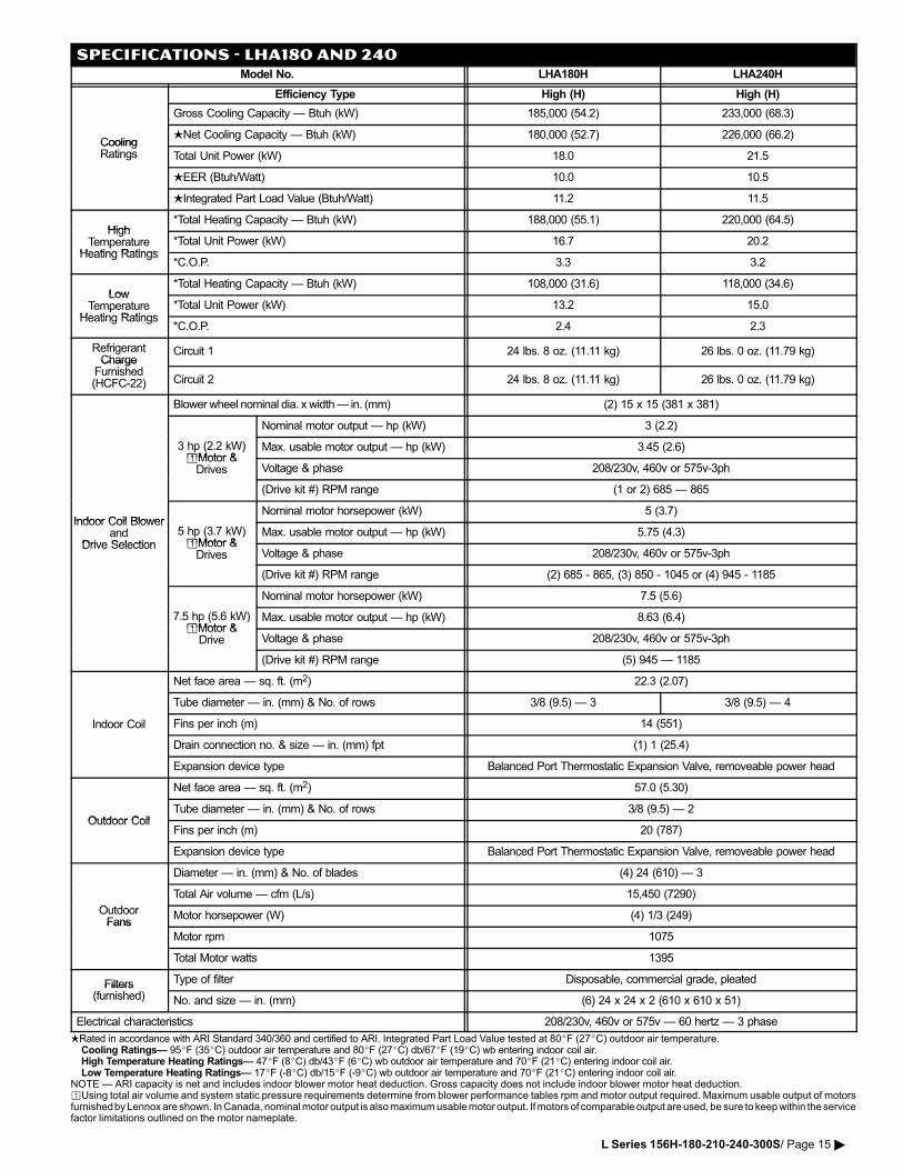
SPECIFICATIONS − LHA180 AND 240Model No. LHA180H LHA240H
Efficiency Type High (H) High (H)
Gross Cooling Capacity � Btuh (kW) 185,000 (54.2) 233,000 (68.3)
CoolingNet Cooling Capacity � Btuh (kW) 180,000 (52.7) 226,000 (66.2)
CoolingRatings Total Unit Power (kW) 18.0 21.5
EER (Btuh/Watt) 10.0 10.5
Integrated Part Load Value (Btuh/Watt) 11.2 11.5
High*Total Heating Capacity � Btuh (kW) 188,000 (55.1) 220,000 (64.5)
HighTemperature
Heating Ratings*Total Unit Power (kW) 16.7 20.2p
Heating Ratings*C.O.P. 3.3 3.2
Low*Total Heating Capacity � Btuh (kW) 108,000 (31.6) 118,000 (34.6)
LowTemperature
Heating Ratings*Total Unit Power (kW) 13.2 15.0p
Heating Ratings*C.O.P. 2.4 2.3
RefrigerantCharge
Circuit 1 24 lbs. 8 oz. (11.11 kg) 26 lbs. 0 oz. (11.79 kg)Charge
Furnished(HCFC�22) Circuit 2 24 lbs. 8 oz. (11.11 kg) 26 lbs. 0 oz. (11.79 kg)
Blower�wheel�nominal�dia.�x�width���in.�(mm) (2) 15 x 15 (381 x 381)
Nominal motor output � hp (kW) 3 (2.2)
3 hp (2.2 kW)�Motor &
Max. usable motor output � hp (kW) 3.45 (2.6)�Motor &Drives Voltage & phase 208/230v, 460v or 575v�3ph
(Drive kit #) RPM range (1 or 2) 685 � 865
Indoor Coil BlowerNominal motor horsepower (kW) 5 (3.7)
Indoor Coil Blowerand
Drive Selection5 hp (3.7 kW)�Motor &
Max. usable motor output � hp (kW) 5.75 (4.3)Drive Selection �Motor &
Drives Voltage & phase 208/230v, 460v or 575v�3ph
(Drive kit #) RPM range (2) 685 − 865, (3) 850 − 1045 or (4) 945 − 1185
Nominal motor horsepower (kW) 7.5 (5.6)
7.5 hp (5.6 kW)�Motor &
Max. usable motor output � hp (kW) 8.63 (6.4)�Motor &
Drive Voltage & phase 208/230v, 460v or 575v�3ph
(Drive kit #) RPM range (5) 945 � 1185
Net face area � sq. ft. (m2) 22.3 (2.07)
Tube diameter � in. (mm) & No. of rows 3/8 (9.5) � 3 3/8 (9.5) � 4
Indoor Coil Fins per inch (m) 14 (551)
Drain connection no. & size � in. (mm) fpt (1) 1 (25.4)
Expansion device type Balanced Port Thermostatic Expansion Valve, removeable power head
Net face area � sq. ft. (m2) 57.0 (5.30)
Outdoor CoilTube diameter � in. (mm) & No. of rows 3/8 (9.5) � 2
Outdoor CoilFins per inch (m) 20 (787)
Expansion device type Balanced Port Thermostatic Expansion Valve, removeable power head
Diameter � in. (mm) & No. of blades (4) 24 (610) � 3
Total Air volume � cfm (L/s) 15,450 (7290)
OutdoorFans
Motor horsepower (W) (4) 1/3 (249)Fans
Motor rpm 1075
Total Motor watts 1395
Filters Type of filter Disposable, commercial grade, pleatedFilters(furnished) No. and size � in. (mm) (6) 24 x 24 x 2 (610 x 610 x 51)
Electrical characteristics 208/230v, 460v or 575v � 60 hertz � 3 phase
Rated in accordance with ARI Standard 340/360 and certified to ARI. Integrated Part Load Value tested at 80�F (27�C) outdoor air temperature.Cooling Ratings� 95�F (35�C) outdoor air temperature and 80�F (27�C) db/67�F (19�C) wb entering indoor coil air.High Temperature Heating Ratings� 47�F (8�C) db/43�F (6�C) wb outdoor air temperature and 70�F (21�C) entering indoor coil air.Low Temperature Heating Ratings� 17�F (�8�C) db/15�F (�9�C) wb outdoor air temperature and 70�F (21�C) entering indoor coil air.
NOTE � ARI capacity is net and includes indoor blower motor heat deduction. Gross capacity does not include indoor blower motor heat deduction.�Using total air volume and system static pressure requirements determine from blower performance tables rpm and motor output required. Maximum usable output of motorsfurnished by Lennox are shown. In Canada, nominal motor output is also maximum usable motor output. If motors of comparable output are used, be sure to keep within the servicefactor limitations outlined on the motor nameplate.
L Series 156H−180−210−240−300S/ Page 15 �
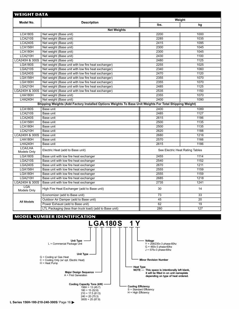
WEIGHT DATA
Model No DescriptionWeight
Model No. Descriptionlbs. kg
Net Weights
LCA180S Net weight (Base unit) 2200 1000
LCA210S Net weight (Base unit) 2285 1035
LCA240S Net weight (Base unit) 2415 1095
LCA156H Net weight (Base unit) 2300 1045
LCA180H Net weight (Base unit) 2300 1045
LCA210H Net weight (Base unit) 2430 1100
LCA240H & 300S Net weight (Base unit) 2480 1125
LGA180S Net weight (Base unit with low fire heat exchanger) 2255 1025
LGA210S Net weight (Base unit with low fire heat exchanger) 2340 1060
LGA240S Net weight (Base unit with low fire heat exchanger) 2470 1120
LGA156H Net weight (Base unit with low fire heat exchanger) 2355 1070
LGA180H Net weight (Base unit with low fire heat exchanger) 2355 1070
LGA210H Net weight (Base unit with low fire heat exchanger) 2485 1125
LGA240H & 300S Net weight (Base unit with low fire heat exchanger) 2535 1150
LHA180H Net weight (Base unit) 2355 1070
LHA240H Net weight (Base unit) 2400 1090
Shipping Weights (Add Factory Installed Options Weights To Base Unit Weights For Total Shipping Weight)
LCA180S Base unit 2400 1089
LCA210S Base unit 2485 1127
LCA240S Base unit 2615 1186
LCA156H Base unit 2500 1135
LCA180H Base unit 2500 1135
LCA210H Base unit 2620 1188
LCA240H & 300S Base unit 2680 1216
LHA180H Base unit 2570 1166
LHA240H Base unit 2615 1186
LCA/LHAModels Only
Electric Heat (add to Base unit) See Electric Heat Rating Tables
LGA180S Base unit with low fire heat exchanger 2455 1114
LGA210S Base unit with low fire heat exchanger 2540 1152
LGA240S Base unit with low fire heat exchanger 2670 1211
LGA156H Base unit with low fire heat exchanger 2555 1159
LGA180H Base unit with low fire heat exchanger 2555 1159
LGA210H Base unit with low fire heat exchanger 2685 1218
LGA240H & 300S Base unit with low fire heat exchanger 2735 1241
LGAModels Only
High Fire Heat Exchanger (add to Base unit) 30 14
Economizer (add to Base unit) 73 33
All ModelsOutdoor Air Damper (add to Base unit) 45 20
All ModelsPower Exhaust (add to Base unit) 62 19
LTL Packaging (less than truck load) (add to Base unit) 280 127
MODEL NUMBER IDENTIFICATION
Minor Revision Number
LGA Y
Unit TypeL = Commercial Package Unit
Unit TypeG = Cooling w/ Gas HeatC = Cooling Only (w/ opt. Electric Heat)H = Heat Pump
Major Design SequenceA = First Generation
1180
Cooling Capacity Tons (kW)156H = 13 (45.7)180 = 15 (52.8)210 = 17.5 (61.5)240 = 20 (70.3)300S = 25 (87.9)
S
Cooling EfficiencyS = Standard EfficiencyH = High Efficiency
Heat TypeNOTE � This space is intentionally left blank,
it will be filled in on unit nameplatedepending on type of heat ordered.
VoltageY = 208/230v�3 phase�60hzG = 460v�3 phase�60hzJ = 575v�3 phase�60hz
L Series 156H−180−210−240−300S/ Page 16 �
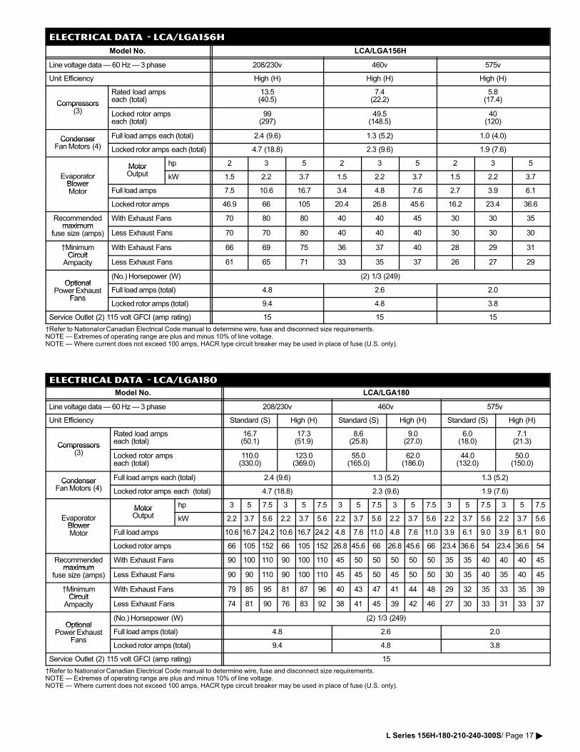
ELECTRICAL DATA − lca/lga156h
Model�No. LCA/LGA156H
Line�voltage�data���60�Hz���3�phase 208/230v 460v 575v
Unit Efficiency High (H) High (H) High (H)
Compressors
Rated load ampseach (total)
13.5(40.5)
7.4(22.2)
5.8(17.4)
Compressors(3) Locked rotor amps
each (total)99
(297)49.5
(148.5)40
(120)
Condenser Full�load�amps each�(total) 2.4 (9.6) 1.3 (5.2) 1.0 (4.0)CondenserFan�Motors (4) Locked�rotor�amps each�(total) 4.7 (18.8) 2.3 (9.6) 1.9 (7.6)
Motor hp 2 3 5 2 3 5 2 3 5
EvaporatorBlower
MotorOutput kW 1.5 2.2 3.7 1.5 2.2 3.7 1.5 2.2 3.7
BlowerMotor Full�load�amps 7.5 10.6 16.7 3.4 4.8 7.6 2.7 3.9 6.1
Locked�rotor�amps 46.9 66 105 20.4 26.8 45.6 16.2 23.4 36.6
Recommendedmaximum
With Exhaust Fans 70 80 80 40 40 45 30 30 35maximum
fuse size (amps) Less Exhaust Fans 70 70 80 40 40 40 30 30 30
MinimumCircuit
With Exhaust Fans 66 69 75 36 37 40 28 29 31Circuit
Ampacity Less Exhaust Fans 61 65 71 33 35 37 26 27 29
Optional(No.)�Horsepower (W) (2) 1/3 (249)
OptionalPower�Exhaust
FansFull�load�amps�(total) 4.8 2.6 2.0
FansLocked�rotor�amps�(total) 9.4 4.8 3.8
Service Outlet (2) 115 volt GFCI (amp rating) 15 15 15
Refer�to�National or Canadian�Electrical�Code�manual�to�determine�wire,�fuse�and�disconnect�size�requirements.NOTE���Extremes�of�operating�range�are�plus�and�minus�10%�of�line�voltage.NOTE � Where current does not exceed 100 amps, HACR type circuit breaker may be used in place of fuse (U.S. only).
ELECTRICAL DATA − lca/lga180
Model�No. LCA/LGA180
Line�voltage�data���60�Hz���3�phase 208/230v 460v 575v
Unit Efficiency Standard (S) High (H) Standard (S) High (H) Standard (S) High (H)
Compressors
Rated load ampseach (total)
16.7(50.1)
17.3(51.9)
8.6(25.8)
9.0(27.0)
6.0(18.0)
7.1(21.3)
Compressors(3) Locked rotor amps
each (total)110.0(330.0)
123.0(369.0)
55.0(165.0)
62.0(186.0)
44.0(132.0)
50.0(150.0)
Condenser Full�load�amps each�(total) 2.4 (9.6) 1.3 (5.2) 1.3 (5.2)CondenserFan�Motors (4) Locked�rotor�amps each �(total) 4.7 (18.8) 2.3 (9.6) 1.9 (7.6)
Motor hp 3 5 7.5 3 5 7.5 3 5 7.5 3 5 7.5 3 5 7.5 3 5 7.5
EvaporatorBlower
MotorOutput kW 2.2 3.7 5.6 2.2 3.7 5.6 2.2 3.7 5.6 2.2 3.7 5.6 2.2 3.7 5.6 2.2 3.7 5.6
BlowerMotor Full�load�amps 10.6 16.7 24.2 10.6 16.7 24.2 4.8 7.6 11.0 4.8 7.6 11.0 3.9 6.1 9.0 3.9 6.1 9.0
Locked�rotor�amps 66 105 152 66 105 152 26.8 45.6 66 26.8 45.6 66 23.4 36.6 54 23.4 36.6 54
Recommendedmaximum
With Exhaust Fans 90 100 110 90 100 110 45 50 50 50 50 50 35 35 40 40 40 45maximum
fuse size (amps) Less Exhaust Fans 90 90 110 90 100 110 45 45 50 45 50 50 30 35 40 35 40 45
MinimumCircuit
With Exhaust Fans 79 85 95 81 87 96 40 43 47 41 44 48 29 32 35 33 35 39Circuit
Ampacity Less Exhaust Fans 74 81 90 76 83 92 38 41 45 39 42 46 27 30 33 31 33 37
Optional(No.)�Horsepower (W) (2) 1/3 (249)
OptionalPower�Exhaust
FansFull�load�amps�(total) 4.8 2.6 2.0
FansLocked�rotor�amps�(total) 9.4 4.8 3.8
Service Outlet (2) 115 volt GFCI (amp rating) 15
Refer�to�National or Canadian�Electrical�Code�manual�to�determine�wire,�fuse�and�disconnect�size�requirements.NOTE���Extremes�of�operating�range�are�plus�and�minus�10%�of�line�voltage.NOTE � Where current does not exceed 100 amps, HACR type circuit breaker may be used in place of fuse (U.S. only).
L Series 156H−180−210−240−300S/ Page 17 �
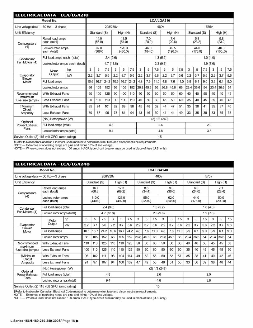
ELECTRICAL DATA − lca/lga210
Model�No. LCA/LGA210
Line�voltage�data���60�Hz���3�phase 208/230v 460v 575v
Unit Efficiency Standard (S) High (H) Standard (S) High (H) Standard (S) High (H)
Compressors
Rated load ampseach (total)
14.0(56.0)
13.5(54.0)
7.0(28.0)
7.4(29.6)
5.8(23.2)
5.8(23.2)
Compressors(4) Locked rotor amps
each (total)92.0(368.0
120.0(480.0)
46.0(184.0)
49.5(198.0)
44.0(176.0)
40.0(160..0)
Condenser Full�load�amps each �(total) 2.4 (9.6) 1.3 (5.2) 1.0 (4.0)CondenserFan�Motors (4) Locked�rotor�amps each �(total) 4.7 (18.8) 2.3 (9.6) 1.9 (7.6)
Motor hp 3 5 7.5 3 5 7.5 3 5 7.5 3 5 7.5 3 5 7.5 3 5 7.5
EvaporatorBlower
MotorOutput kW 2.2 3.7 5.6 2.2 3.7 5.6 2.2 3.7 5.6 2.2 3.7 5.6 2.2 3.7 5.6 2.2 3.7 5.6
BlowerMotor Full�load�amps 10.6 16.7 24.2 10.6 16.7 24.2 4.8 7.6 11.0 4.8 7.6 11.0 3.9 6.1 9.0 3.9 6.1 9.0
Locked�rotor�amps 66 105 152 66 105 152 26.8 45.6 66 26.8 45.6 66 23.4 36.6 54 23.4 36.6 54
Recommendedmaximum
With Exhaust Fans 90 100 125 90 100 110 50 50 60 50 50 60 40 40 50 40 40 45maximum
fuse size (amps) Less Exhaust Fans 90 100 110 90 100 110 45 50 60 45 50 60 35 40 45 35 40 45
MinimumCircuit
With Exhaust Fans 85 91 101 82 89 98 45 48 52 44 47 51 35 38 41 35 37 40Circuit
Ampacity Less Exhaust Fans 80 87 96 78 84 94 43 46 50 41 44 49 33 35 39 33 35 38
Optional(No.)�Horsepower (W) (2) 1/3 (249)
OptionalPower�Exhaust
FansFull�load�amps�(total) 4.8 2.6 2.0
FansLocked�rotor�amps�(total) 9.4 4.8 3.8
Service Outlet (2) 115 volt GFCI (amp rating) 15
Refer�to�National or Canadian�Electrical�Code�manual�to�determine�wire,�fuse�and�disconnect�size�requirements.NOTE���Extremes�of�operating�range�are�plus�and�minus�10%�of�line�voltage.NOTE � Where current does not exceed 100 amps, HACR type circuit breaker may be used in place of fuse (U.S. only).
ELECTRICAL DATA − lca/lga240
Model�No. LCA/LGA240
Line�voltage�data���60�Hz���3�phase 208/230v 460v 575v
Unit Efficiency Standard (S) High (H) Standard (S) High (H) Standard (S) High (H)
Compressors
Rated load ampseach (total)
16.7(66.8)
17.3(69.2)
8.6(34.4)
9.0(36.0)
6.0(24.0)
7.1(28.4)
Compressors(4) Locked rotor amps
each (total)110.0(440.0)
123.0(492.0)
55.0(220.0)
62.0(248.0)
44.0(176.0)
50.0(200.0)
Condenser Full�load�amps�(total) 2.4 (9.6) 1.3 (5.2) 1.0 (4.0)CondenserFan�Motors (4) Locked�rotor�amps�(total) 4.7 (18.8) 2.3 (9.6) 1.9 (7.6)
Motor hp 3 5 7.5 3 5 7.5 3 5 7.5 3 5 7.5 3 5 7.5 3 5 7.5
EvaporatorBlower
MotorOutput kW 2.2 3.7 5.6 2.2 3.7 5.6 2.2 3.7 5.6 2.2 3.7 5.6 2.2 3.7 5.6 2.2 3.7 5.6
BlowerMotor Full�load�amps 10.6 16.7 24.2 10.6 16.7 24.2 4.8 7.6 11.0 4.8 7.6 11.0 3.9 6.1 9.0 3.9 6.1 9.0
Locked�rotor�amps 66 105 152 66 105 152 26.8 45.6 66 26.8 45.6 66 23.4 36.6 54 23.4 36.6 54
Recommendedmaximum
With Exhaust Fans 110 110 125 110 110 125 50 60 60 50 60 60 40 40 50 45 45 50maximum
fuse size (amps) Less Exhaust Fans 100 110 125 110 110 125 50 50 60 50 60 60 35 40 45 45 45 50
MinimumCircuit
With Exhaust Fans 96 102 111 98 104 114 49 52 56 50 53 57 35 38 41 40 42 46Circuit
Ampacity Less Exhaust Fans 91 97 107 94 100 109 47 49 53 48 51 55 33 36 39 38 40 44
Optional(No.)�Horsepower (W) (2) 1/3 (249)
OptionalPower�Exhaust
FansFull�load�amps�(total) 4.8 2.6 2.0
FansLocked�rotor�amps�(total) 9.4 4.8 3.8
Service Outlet (2) 115 volt GFCI (amp rating) 15
Refer�to�National or Canadian�Electrical�Code�manual�to�determine�wire,�fuse�and�disconnect�size�requirements.NOTE���Extremes�of�operating�range�are�plus�and�minus�10%�of�line�voltage.NOTE � Where current does not exceed 100 amps, HACR type circuit breaker may be used in place of fuse (U.S. only).
L Series 156H−180−210−240−300S/ Page 18 �
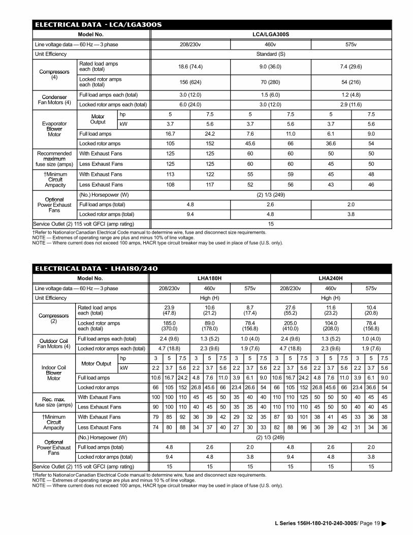
ELECTRICAL DATA − lca/lga300S
Model�No. LCA/LGA300S
Line�voltage�data���60�Hz���3�phase 208/230v 460v 575v
Unit Efficiency Standard (S)
Compressors
Rated load ampseach (total) 18.6 (74.4) 9.0 (36.0) 7.4 (29.6)
Compressors(4) Locked rotor amps
each (total) 156 (624) 70 (280) 54 (216)
Condenser Full�load�amps each�(total) 3.0 (12.0) 1.5 (6.0) 1.2 (4.8)CondenserFan�Motors (4) Locked�rotor�amps each�(total) 6.0 (24.0) 3.0 (12.0) 2.9 (11.6)
Motor hp 5 7.5 5 7.5 5 7.5
EvaporatorBlower
MotorOutput kW 3.7 5.6 3.7 5.6 3.7 5.6
BlowerMotor Full�load�amps 16.7 24.2 7.6 11.0 6.1 9.0
Locked�rotor�amps 105 152 45.6 66 36.6 54
Recommendedmaximum
With Exhaust Fans 125 125 60 60 50 50maximum
fuse size (amps) Less Exhaust Fans 125 125 60 60 45 50
MinimumCircuit
With Exhaust Fans 113 122 55 59 45 48Circuit
Ampacity Less Exhaust Fans 108 117 52 56 43 46
Optional(No.)�Horsepower (W) (2) 1/3 (249)
OptionalPower�Exhaust
FansFull�load�amps�(total) 4.8 2.6 2.0
FansLocked�rotor�amps�(total) 9.4 4.8 3.8
Service Outlet (2) 115 volt GFCI (amp rating) 15
Refer�to�National or Canadian�Electrical�Code�manual�to�determine�wire,�fuse�and�disconnect�size�requirements.NOTE���Extremes�of�operating�range�are�plus�and�minus�10%�of�line�voltage.NOTE � Where current does not exceed 100 amps, HACR type circuit breaker may be used in place of fuse (U.S. only).
ELECTRICAL DATA − LHA180/240
Model�No. LHA180H LHA240H
Line�voltage�data���60�Hz���3�phase 208/230v 460v 575v 208/230v 460v 575v
Unit Efficiency High (H) High (H)
Compressors
Rated load ampseach (total)
23.9(47.8)
10.6(21.2)
8.7(17.4)
27.6(55.2)
11.6(23.2)
10.4(20.8)
Compressors(2) Locked rotor amps
each (total)185.0(370.0)
89.0(178.0)
78.4(156.8)
205.0(410.0)
104.0(208.0)
78.4(156.8)
Outdoor Coil Full�load�amps each�(total) 2.4 (9.6) 1.3 (5.2) 1.0 (4.0) 2.4 (9.6) 1.3 (5.2) 1.0 (4.0)Outdoor CoilFan�Motors (4) Locked�rotor�amps each�(total) 4.7 (18.8) 2.3 (9.6) 1.9 (7.6) 4.7 (18.8) 2.3 (9.6) 1.9 (7.6)
Motor Outputhp 3 5 7.5 3 5 7.5 3 5 7.5 3 5 7.5 3 5 7.5 3 5 7.5
Indoor CoilBlower
Motor OutputkW 2.2 3.7 5.6 2.2 3.7 5.6 2.2 3.7 5.6 2.2 3.7 5.6 2.2 3.7 5.6 2.2 3.7 5.6
BlowerMotor Full�load�amps 10.6 16.7 24.2 4.8 7.6 11.0 3.9 6.1 9.0 10.6 16.7 24.2 4.8 7.6 11.0 3.9 6.1 9.0
Locked�rotor�amps 66 105 152 26.8 45.6 66 23.4 26.6 54 66 105 152 26.8 45.6 66 23.4 36.6 54
Rec. max. With Exhaust Fans 100 100 110 45 45 50 35 40 40 110 110 125 50 50 50 40 45 45Rec. max.fuse size (amps) Less Exhaust Fans 90 100 110 40 45 50 35 35 40 110 110 110 45 50 50 40 40 45
MinimumCircuit
With Exhaust Fans 79 85 92 36 39 42 29 32 35 87 93 101 38 41 45 33 36 38Circuit
Ampacity Less Exhaust Fans 74 80 88 34 37 40 27 30 33 82 88 96 36 39 42 31 34 36
Optional(No.)�Horsepower (W) (2) 1/3 (249)
OptionalPower�Exhaust
FansFull�load�amps�(total) 4.8 2.6 2.0 4.8 2.6 2.0
FansLocked�rotor�amps�(total) 9.4 4.8 3.8 9.4 4.8 3.8
Service Outlet (2) 115 volt GFCI (amp rating) 15 15 15 15 15 15
Refer�to�National or Canadian�Electrical�Code�manual�to�determine�wire,�fuse�and�disconnect�size�requirements.NOTE���Extremes�of�operating�range�are�plus�and�minus�10�%�of�line�voltage.NOTE � Where current does not exceed 100 amps, HACR type circuit breaker may be used in place of fuse (U.S. only).
L Series 156H−180−210−240−300S/ Page 19 �
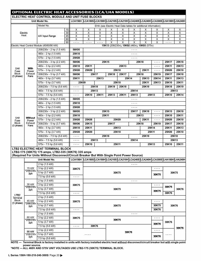
OPTIONAL ELECTRIC HEAT ACCESSORIES (LCA/LHA MODELS)
ELECTRIC HEAT CONTROL MODULE AND UNIT FUSE BLOCKS
Unit Model No. LCA156H LCA180S LCA180H LCA210S LCA210H LCA240S LCA240H LCA300S LHA180H LHA240H
Model No. EHA (see Electric Heat Data tables for additional information)
15 X X X X X X X X X X
Electric 30 X X X X X X X X X XElectricHeat kW Input Range 45 X X X X X X X X X XkW Input Range
60 X X X X X X X X X X
90 − − − − − − − − − − − − X X X X X − − − − X
Electric Heat Control Module (45/60/90 kW) 15K13 (208/230v), 15K92 (460v), 15K93 (575v)
208/230v − 2 hp (1.5 kW) 56K95 − − − −
460v − 2 hp (1.5 kW) 25K10 − − − −
575v − 2 hp (1.5 kW) 25K08 − − − −
208/230v − 3 hp (2.2 kW) 56K96 25K15 25K18 − − − − 25K17 25K18
Unit With460v − 3 hp (2.2 kW) 25K10 25K11 25K13 − − − − 25K11 25K13
UnitFuse
WithPower 575v − 3 hp (2.2 kW) 25K08 25K09 25K10 25K11 − − − − 25K09 25K10Fuse
Block(3 phase)
PowerExhaustFans
208/230v − 5 hp (3.7 kW) 56K96 25K17 25K18 25K17 25K18 25K19 25K17 25K18(3 phase) Fans
460v − 5 hp (3.7 kW) 25K11 25K13 25K14 25K13 25K14 25K11 25K13
575v − 5 hp (3.7 kW) 25K09 25K10 25K11 25K13 25K10 25K11
208/230v − 7.5 hp (5.6 kW) − − − − 25K18 25K19 25K18 25K19 25K18 25K19
460v − 7.5 hp (5.6 kW) − − − − 25K13 25K14 25K13
575v − 7.5 hp (5.6 kW) − − − − 25K10 25K11 25K13 25K11 25K13 25K13 25K10 25K14
208/230v − 2 hp (1.5 kW) 56K95 − − − −
460v − 2 hp (1.5 kW) 25K10 − − − −
575v − 2 hp (1.5 kW) 25K08 − − − −
208/230v − 3 hp (2.2 kW) 56K95 25K15 25K17 25K18 − − − − 25K15 25K18
Unit Without460v − 3 hp (2.2 kW) 25K10 25K11 25K13 − − − − 25K10 25K11
UnitFuse
WithoutPower 575v − 3 hp (2.2 kW) 25K08 25K08 25K09 25K11 − − − − 25K09 25K10Fuse
Block(3 phase)
PowerExhaustFans
208/230v − 5 hp (3.7 kW) 56K96 25K15 25K17 25K18 25K19 25K17 25K18(3 phase) Fans
460v − 5 hp (3.7 kW) 25K10 25K11 25K13 25K14 25K11 25K13
575v − 5 hp (3.7 kW) 25K08 25K09 25K10 25K11 25K09 25K10
208/230v − 7.5 hp (5.6 kW) − − − − 25K18 25K19 25K18
460v − 7.5 hp (5.6 kW) − − − − 25K13 25K14 25K13
575v − 7.5 hp (5.6 kW) − − − − 25K10 25K11 25K13 25K10 25K11
LTB2 ELECTRIC HEAT TERMINAL BLOCKLTB2−175 (30K75) 175 amps, LTB2−335 (30K76) 335 amps(Required For Units Without Disconnect/Circuit Breaker But With Single Point Power Source)
Unit Model No. LCA156H LCA180S LCA180H LCA210S LCA210H LCA240S LCA240H LCA300S LHA180H LHA240H
2 hp (1.5 kW) − − − −
15 kW*208/230v
3 hp (2.2 kW) 30K75 − − − −*208/230v
3ph 5 hp (3.7 kW)
30K75
30K7530K75
30K753ph7.5 hp (5.6 kW) − − − −
30K75
2 hp (1.5 kW) − − − −
30 kW*208/230v
3 hp (2.2 kW) 30K75 − − − −30K75*208/230v
3ph 5 hp (3.7 kW) 30K7530K75
30K7530K76
LTB2
3ph
7.5 hp (5.6 kW) − − − −30K75
30K76LTB2
TerminalBl k
2 hp (1.5 kW) − − − −TerminalBlock
(3 phase)45 kW
*208/230v3 hp (2.2 kW) 30K75 − − − −
(3 phase) *208/230v3ph 5 hp (3.7 kW) 30K75 30K75 30K763ph
7.5 hp (5.6 kW) − − − − 30K76
2 hp (1.5 kW) − − − −
60 kW*208/230v
3 hp (2.2 kW) 30K7530K75
− − − −*208/230v
3ph 5 hp (3.7 kW)30K75
30K7630K763ph
7.5 hp (5.6 kW) − − − − 30K7630K76
30K76
90 kW3 hp (2.2 kW)
30K76− − − −
30K76
90 kW*208/230v
3ph5 hp (3.7 kW) − − − −
30K76
30K76− − − −
3ph7.5 hp (5.6 kW)
30K76
NOTE � Terminal Block is factory installed in units with factory installed electric heat without disconnect/circuit breaker but with single pointpower source.
*NOTE �ALL 460V AND 575V UNIT VOLTAGES USE LTB2�175 (30K75) TERMINAL BLOCK.
L Series 156H−180−210−240−300S/ Page 20 �
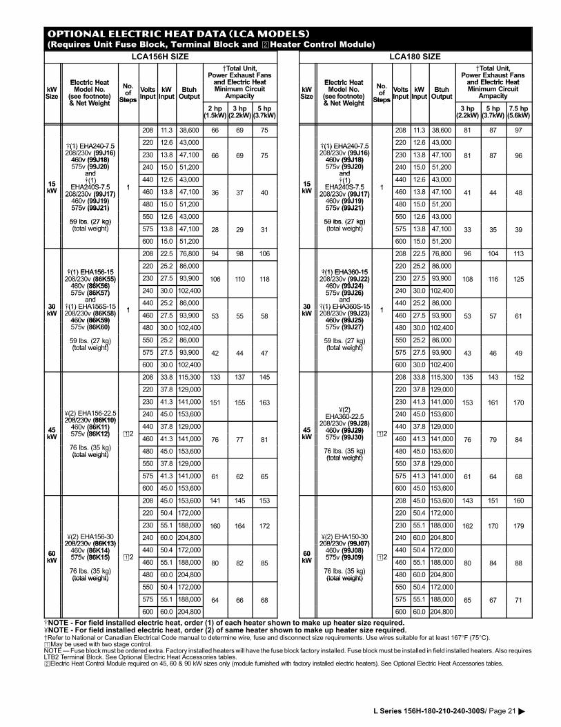
OPTIONAL ELECTRIC HEAT DATA (LCA MODELS)(Requires Unit Fuse Block, Terminal Block and �Heater Control Module)
LCA156H SIZE
Electric Heat
Total Unit,Power Exhaust Fansand Electric Heat
kWSize
Electric HeatModel No.
(see footnote)& N t W i ht
No.of
Steps
VoltsInput
kWInput
BtuhOutput
and Electric HeatMinimum Circuit
AmpacitySize (see footnote)& Net Weight
StepsInput Input Output
2 hp(1.5kW)
3 hp(2.2kW)
5 hp(3.7kW)
208 11.3 38,600 66 69 75
�(1) EHA240�7.5220 12.6 43,000
�(1) EHA240�7.5208/230v (99J16)460v (99J18)
230 13.8 47,100 66 69 75460v (99J18)575v (99J20)
and240 15.0 51,200
15
and�(1)
EHA240S 7 5 1440 12.6 43,000
15kW
�( )EHA240S�7.5
208/230v (99J17)460 (99J19)
1460 13.8 47,100 36 37 40208/230v (99J17)
460v (99J19)575v (99J21)
480 15.0 51,200575v (99J21)
59 lbs. (27 kg)550 12.6 43,000
59 lbs. (27 kg)(total weight) 575 13.8 47,100 28 29 31
600 15.0 51,200
208 22.5 76,800 94 98 106
�(1) EHA156�15220 25.2 86,000
�(1) EHA156�15208/230v (86K55)460v (86K56)
230 27.5 93,900 106 110 118( )460v (86K56)575v (86K57)
d
240 30.0 102,400
30
575v (86K57)and
�(1) EHA156S�151
440 25.2 86,00030kW
�(1) EHA156S�15208/230v (86K58)460v (86K59)
1460 27.5 93,900 53 55 58
460v (86K59)575v (86K60) 480 30.0 102,400
59 lbs. (27 kg)(total weight)
550 25.2 86,000( g)(total weight)
575 27.5 93,900 42 44 47
600 30.0 102,400
208 33.8 115,300 133 137 145
220 37.8 129,000
230 41.3 141,000 151 155 163
�(2) EHA156�22.5208/230v (86K10)
240 45.0 153,600
45
208/230v (86K10)460v (86K11)575v (86K12) �2
440 37.8 129,00045kW
( )575v (86K12)
76 lb (35 k )
�2460 41.3 141,000 76 77 81
76 lbs. (35 kg)(total weight) 480 45.0 153,600(total weight)
550 37.8 129,000
575 41.3 141,000 61 62 65
600 45.0 153,600
208 45.0 153,600 141 145 153
220 50.4 172,000
230 55.1 188,000 160 164 172
�(2) EHA156�30208/230v (86K13)
240 60.0 204,800
60
208/230v (86K13)460v (86K14)575v (86K15) �2
440 50.4 172,00060kW
( )575v (86K15)
76 lb (35 k )
�2460 55.1 188,000 80 82 85
76 lbs. (35 kg)(total weight) 480 60.0 204,800(total weight)
550 50.4 172,000
575 55.1 188,000 64 66 68
600 60.0 204,800
LCA180 SIZE
Electric Heat
Total Unit,Power Exhaust Fansand Electric Heat
kWSize
Electric HeatModel No.
(see�footnote)& N t W i ht
No.of
Steps
VoltsInput
kWInput
BtuhOutput
and Electric HeatMinimum Circuit
AmpacitySize (see�footnote)& Net Weight
StepsInput Input Output
3 hp(2.2kW)
5 hp(3.7kW)
7.5 hp(5.6kW)
208 11.3 38,600 81 87 97
�(1) EHA240�7.5220 12.6 43,000
�(1) EHA240�7.5208/230v (99J16)460v (99J18)
230 13.8 47,100 81 87 96460v (99J18)575v (99J20)
and240 15.0 51,200
15
and�(1)
EHA240S 7 5 1440 12.6 43,000
15kW
�( )EHA240S�7.5
208/230v (99J17)460 (99J19)
1460 13.8 47,100 41 44 48208/230v (99J17)
460v (99J19)575v (99J21)
480 15.0 51,200575v (99J21)
59 lbs. (27 kg)550 12.6 43,000
59 lbs. (27 kg)(total weight) 575 13.8 47,100 33 35 39
600 15.0 51,200
208 22.5 76,800 96 104 113
�(1) EHA360�15220 25.2 86,000
�(1) EHA360�15208/230v (99J22)460v (99J24)
230 27.5 93,900 108 116 125( )460v (99J24)575v (99J26)
d
240 30.0 102,400
30
575v (99J26)and
�(1) EHA360S�151
440 25.2 86,00030kW
�(1) EHA360S�15208/230v (99J23)460v (99J25)
1460 27.5 93,900 53 57 61
460v (99J25)575v (99J27) 480 30.0 102,400
59 lbs. (27 kg)(total weight)
550 25.2 86,000( g)(total weight)
575 27.5 93,900 43 46 49
600 30.0 102,400
208 33.8 115,300 135 143 152
220 37.8 129,000
�(2)230 41.3 141,000 153 161 170
�(2)EHA360�22.5
208/230 (99J28)
240 45.0 153,600
45
EHA360 22.5208/230v (99J28)460v (99J29) �2
440 37.8 129,00045kW
460v (99J29)575v (99J30)
�2460 41.3 141,000 76 79 84
76 lbs. (35 kg)(total weight)
480 45.0 153,600(total weight)
550 37.8 129,000
575 41.3 141,000 61 64 68
600 45.0 153,600
208 45.0 153,600 143 151 160
220 50.4 172,000
230 55.1 188,000 162 170 179
�(2) EHA150�30208/230v (99J07)
240 60.0 204,800
60
208/230v (99J07)460v (99J08)575v (99J09) �2
440 50.4 172,00060kW
( )575v (99J09)
76 lb (35 k )
�2460 55.1 188,000 80 84 88
76 lbs. (35 kg)(total weight) 480 60.0 204,800(total weight)
550 50.4 172,000
575 55.1 188,000 65 67 71
600 60.0 204,800
�NOTE − For field installed electric heat, order (1) of each heater shown to make up heater size required.�NOTE − For field installed electric heat, order (2) of same heater shown to make up heater size required.Refer to National or Canadian Electrical Code manual to determine wire, fuse and disconnect size requirements. Use wires suitable for at least 167°F (75°C).�May be used with two stage control.NOTE � Fuse block must be ordered extra. Factory installed heaters will have the fuse block factory installed. Fuse block must be installed in field installed heaters. Also requiresLTB2 Terminal Block. See Optional Electric Heat Accessories tables.�Electric Heat Control Module required on 45, 60 & 90 kW sizes only (module furnished with factory installed electric heaters). See Optional Electric Heat Accessories tables.
L Series 156H−180−210−240−300S/ Page 21 �
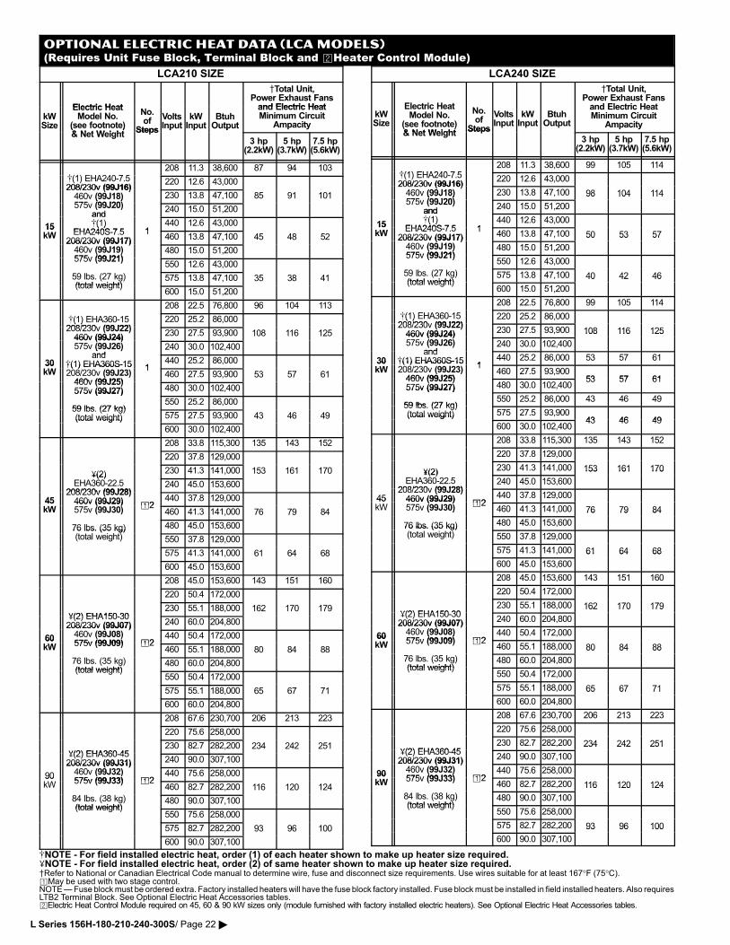
OPTIONAL ELECTRIC HEAT DATA (LCA MODELS)(Requires Unit Fuse Block, Terminal Block and �Heater Control Module)
LCA210 SIZE
Electric Heat
Total Unit,Power Exhaust Fansand Electric Heat
kWSize
Electric HeatModel No.
(see footnote)& N t W i ht
No.of
Steps
VoltsInput
kWInput
BtuhOutput
and Electric HeatMinimum Circuit
AmpacitySize (see footnote)& Net Weight
StepsInput Input Output
3 hp(2.2kW)
5 hp(3.7kW)
7.5 hp(5.6kW)
�(1) EHA240 7 5
208 11.3 38,600 87 94 103
�(1) EHA240�7.5208/230v (99J16)
220 12.6 43,000208/230v (99J16)460v (99J18)575 (99J20)
230 13.8 47,100 85 91 101460v (99J18)575v (99J20)
and240 15.0 51,200
15
and�(1)
EHA240S 7 5 1440 12.6 43,00015
kW
�( )EHA240S�7.5
208/230v (99J17)1
460 13.8 47,100 45 48 52208/230v (99J17)460v (99J19)575v (99J21)
480 15.0 51,200( )575v (99J21)
550 12.6 43,000
59 lbs. (27 kg)(total weight)
575 13.8 47,100 35 38 41(total weight)
600 15.0 51,200
208 22.5 76,800 96 104 113
�(1) EHA360�15208/230v (99J22)
220 25.2 86,000�( )208/230v (99J22)460v (99J24)
230 27.5 93,900 108 116 125460v (99J24)575v (99J26)
and240 30.0 102,400
30
( )and
�(1) EHA360S�15 1440 25.2 86,00030
kW�(1) EHA360S�15208/230v (99J23)460v (99J25)
1460 27.5 93,900 53 57 61
460v (99J25)575v (99J27) 480 30.0 102,400575v (99J27)
59 lbs (27 kg)550 25.2 86,000
59 lbs. (27 kg)(total weight) 575 27.5 93,900 43 46 49(total weight)
600 30.0 102,400
208 33.8 115,300 135 143 152
220 37.8 129,000
�(2) 230 41.3 141,000 153 161 170�(2)EHA360�22.5
208/230v (99J28)240 45.0 153,600
45208/230v (99J28)460v (99J29) �2
440 37.8 129,00045kW
460v (99J29)575v (99J30)
�2460 41.3 141,000 76 79 84
76 lbs. (35 kg)(t t l i ht)
480 45.0 153,60076 lbs. (35 kg)(total weight) 550 37.8 129,000
575 41.3 141,000 61 64 68
600 45.0 153,600
208 45.0 153,600 143 151 160
220 50.4 172,000
�(2) EHA150 30230 55.1 188,000 162 170 179
�(2) EHA150�30208/230v (99J07) 240 60.0 204,800
60
208/230v (99J07)460v (99J08)575v (99J09) �2
440 50.4 172,00060kW 575v (99J09) �2
460 55.1 188,000 80 84 88
76 lbs. (35 kg)(total weight)
480 60.0 204,800(total weight)
550 50.4 172,000
575 55.1 188,000 65 67 71
600 60.0 204,800
208 67.6 230,700 206 213 223
220 75.6 258,000
�(2) EHA360 45230 82.7 282,200 234 242 251
�(2) EHA360�45208/230v (99J31) 240 90.0 307,100
90
208/230v (99J31)460v (99J32)575v (99J33) �2
440 75.6 258,00090kW 575v (99J33) �2
460 82.7 282,200 116 120 124
84 lbs. (38 kg)(total weight)
480 90.0 307,100(total weight)
550 75.6 258,000
575 82.7 282,200 93 96 100
600 90.0 307,100
LCA240 SIZE
kWSize
Electric HeatModel No.
(see footnote)& Net Weight
No.of
Steps
VoltsInput
kWInput
BtuhOutput
Total Unit,Power Exhaust Fansand Electric HeatMinimum Circuit
Ampacity( )& Net Weight
Steps
3 hp(2.2kW)
5 hp(3.7kW)
7.5 hp(5.6kW)
�(1) EHA240 7 5208 11.3 38,600 99 105 114
�(1) EHA240�7.5208/230v (99J16)
220 12.6 43,000208/230v (99J16)460v (99J18)575 (99J20)
230 13.8 47,100 98 104 114460v (99J18)575v (99J20)
and240 15.0 51,200
98 104 114
15
and�(1)
EHA240S 7 5 1440 12.6 43,000
15kW
�( )EHA240S�7.5
208/230v (99J17)1
460 13.8 47,100 50 53 57208/230v (99J17)460v (99J19)575v (99J21)
480 15.0 51,200
50 53 57
( )575v (99J21)
550 12.6 43,000
59 lbs. (27 kg)(total weight)
575 13.8 47,100 40 42 46(total weight)
600 15.0 51,200
40 42 46
208 22.5 76,800 99 105 114
�(1) EHA360�15208/230v (99J22)
220 25.2 86,000�( )208/230v (99J22)460v (99J24) 230 27.5 93,900 108 116 125460v (99J24)575v (99J26)
and240 30.0 102,400
108 116 125
30
( )and
�(1) EHA360S�151
440 25.2 86,000 53 57 6130kW
�(1) EHA360S�15208/230v (99J23)460v (99J25)
1460 27.5 93,900
53 57 61460v (99J25)575v (99J27) 480 30.0 102,400
53 57 61575v (99J27)
59 lbs (27 kg)550 25.2 86,000 43 46 49
59 lbs. (27 kg)(total weight) 575 27.5 93,900
43 46 49(total weight)
600 30.0 102,40043 46 49
208 33.8 115,300 135 143 152
220 37.8 129,000
�(2) 230 41.3 141,000 153 161 170�(2)EHA360�22.5
208/230v (99J28)240 45.0 153,600
153 161 170
45208/230v (99J28)460v (99J29) �2
440 37.8 129,00045kW
460v (99J29)575v (99J30)
�2460 41.3 141,000 76 79 84( )
76 lbs. (35 kg) 480 45.0 153,600
76 79 84
76 lbs. (35 kg)(total weight) 550 37.8 129,000
575 41.3 141,000 61 64 68
600 45.0 153,600
61 64 68
208 45.0 153,600 143 151 160
220 50.4 172,000
�(2) EHA150 30230 55.1 188,000 162 170 179
�(2) EHA150�30208/230v (99J07) 240 60.0 204,800
162 170 179
60
208/230v (99J07)460v (99J08)575v (99J09) �2
440 50.4 172,00060kW
( )575v (99J09) �2
460 55.1 188,000 80 84 88
76 lbs. (35 kg)(total weight)
480 60.0 204,800
80 84 88
(total weight)550 50.4 172,000
575 55.1 188,000 65 67 71
600 60.0 204,800
65 67 71
208 67.6 230,700 206 213 223
220 75.6 258,000
�(2) EHA360 45230 82.7 282,200 234 242 251
�(2) EHA360�45208/230v (99J31) 240 90.0 307,100
234 242 251
90
208/230v (99J31)460v (99J32)575v (99J33) �2
440 75.6 258,00090kW
( )575v (99J33) �2
460 82.7 282,200 116 120 124
84 lbs. (38 kg)(total weight)
480 90.0 307,100
116 120 124
(total weight)550 75.6 258,000
575 82.7 282,200 93 96 100
600 90.0 307,100
93 96 100
�NOTE − For field installed electric heat, order (1) of each heater shown to make up heater size required.�NOTE − For field installed electric heat, order (2) of same heater shown to make up heater size required.Refer to National or Canadian Electrical Code manual to determine wire, fuse and disconnect size requirements. Use wires suitable for at least 167°F (75°C).�May be used with two stage control.NOTE � Fuse block must be ordered extra. Factory installed heaters will have the fuse block factory installed. Fuse block must be installed in field installed heaters. Also requiresLTB2 Terminal Block. See Optional Electric Heat Accessories tables.�Electric Heat Control Module required on 45, 60 & 90 kW sizes only (module furnished with factory installed electric heaters). See Optional Electric Heat Accessories tables.
L Series 156H−180−210−240−300S/ Page 22 �
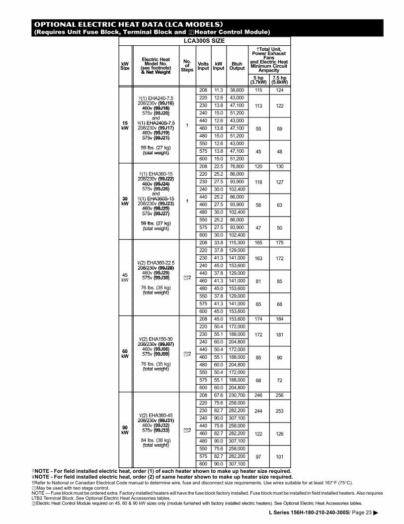
OPTIONAL ELECTRIC HEAT DATA (LCA MODELS)(Requires Unit Fuse Block, Terminal Block and �Heater Control Module)
LCA300S SIZE
kWSize
Electric HeatModel No.
(see footnote)& Net Weight
No.of
Steps
VoltsInput
kWInput
BtuhOutput
Total Unit,Power Exhaust
Fansand Electric HeatMinimum Circuit
Ampacity& Net Weight p
5 hp(3.7kW)
7.5 hp(5.6kW)
208 11.3 38,600 115 124
�(1) EHA240�7.5208/230 (99J16)
220 12.6 43,000�(1) EHA240 7.5208/230v (99J16)460v (99J18)
230 13.8 47,100 113 122460v (99J18)575v (99J20)
and240 15.0 51,200
113 122
15
( )and
�(1) EHA240S�7.51
440 12.6 43,00015kW
�(1) EHA240S�7.5208/230v (99J17)460v (99J19)
1460 13.8 47,100 55 59( )
460v (99J19)575v (99J21) 480 15.0 51,200
55 59
575v (99J21)
59 lbs (27 kg)550 12.6 43,000
59 lbs. (27 kg)(total weight) 575 13.8 47,100 45 48(total weight)
600 15.0 51,200
45 48
208 22.5 76,800 120 130
�(1) EHA360�15208/230v (99J22)
220 25.2 86,000�( )208/230v (99J22)460v (99J24) 230 27.5 93,900 118 127460v (99J24)575v (99J26)
and240 30.0 102,400
118 127
30
( )and
�(1) EHA360S�151
440 25.2 86,00030kW
�(1) EHA360S�15208/230v (99J23)460v (99J25)
1460 27.5 93,900 58 63
460v (99J25)575v (99J27) 480 30.0 102,400
58 63
575v (99J27)
59 lbs (27 kg)550 25.2 86,000
59 lbs. (27 kg)(total weight) 575 27.5 93,900 47 50(total weight)
600 30.0 102,400
47 50
208 33.8 115,300 165 175
220 37.8 129,000
�(2) EHA360 22 5230 41.3 141,000 163 172
�(2) EHA360�22.5208/230v (99J28) 240 45.0 153,600
163 172
45
208/230v (99J28)460v (99J29)575v (99J30) �2
440 37.8 129,00045kW
( )575v (99J30) �2
460 41.3 141,000 81 85
76 lbs. (35 kg)(total weight)
480 45.0 153,600
81 85
(total weight)550 37.8 129,000
575 41.3 141,000 65 68
600 45.0 153,600
65 68
208 45.0 153,600 174 184
220 50.4 172,000
�(2) EHA150 30230 55.1 188,000 172 181
�(2) EHA150�30208/230v (99J07) 240 60.0 204,800
172 181
60
208/230v (99J07)460v (99J08)575v (99J09) �2
440 50.4 172,00060kW
( )575v (99J09) �2
460 55.1 188,000 85 90
76 lbs. (35 kg)(total weight)
480 60.0 204,800
85 90
(total weight)550 50.4 172,000
575 55.1 188,000 68 72
600 60.0 204,800
68 72
208 67.6 230,700 246 256
220 75.6 258,000
�(2) EHA360 45230 82.7 282,200 244 253
�(2) EHA360�45208/230v (99J31) 240 90.0 307,100
244 253
90
208/230v (99J31)460v (99J32)575v (99J33) �2
440 75.6 258,00090kW
( )575v (99J33) �2
460 82.7 282,200 122 126
84 lbs. (38 kg)(total weight)
480 90.0 307,100
122 126
(total weight)550 75.6 258,000
575 82.7 282,200 97 101
600 90.0 307,100
97 101
�NOTE − For field installed electric heat, order (1) of each heater shown to make up heater size required.�NOTE − For field installed electric heat, order (2) of same heater shown to make up heater size required.Refer to National or Canadian Electrical Code manual to determine wire, fuse and disconnect size requirements. Use wires suitable for at least 167°F (75°C).�May be used with two stage control.NOTE � Fuse block must be ordered extra. Factory installed heaters will have the fuse block factory installed. Fuse block must be installed in field installed heaters. Also requiresLTB2 Terminal Block. See Optional Electric Heat Accessories tables.�Electric Heat Control Module required on 45, 60 & 90 kW sizes only (module furnished with factory installed electric heaters). See Optional Electric Heat Accessories tables.
L Series 156H−180−210−240−300S/ Page 23 �
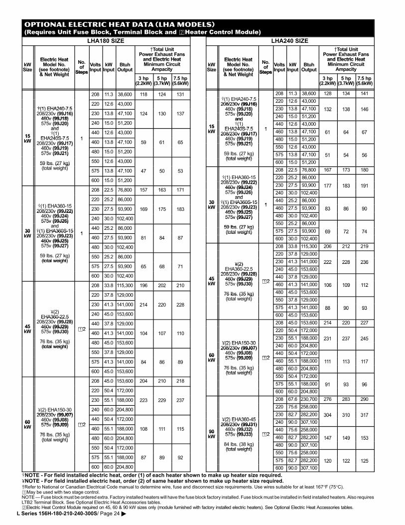
OPTIONAL ELECTRIC HEAT DATA (LHA MODELS)(Requires Unit Fuse Block, Terminal Block and �Heater Control Module)
LHA180 SIZE
Electric Heat
Total UnitPower Exhaust Fansand Electric Heat
kWSize
Electric HeatModel No.
(see footnote)& N t W i ht
No.of
Steps
VoltsInput
kWInput
BtuhOutput
and Electric HeatMinimum Circuit
AmpacitySize (see footnote)& Net Weight
StepsInput Input Output
3 hp(2.2kW)
5 hp(3.7kW)
7.5 hp(5.6kW)
208 11.3 38,600 118 124 131
�(1) EHA240�7 5220 12.6 43,000
�(1) EHA240�7.5208/230v (99J16)460v (99J18)
230 13.8 47,100 124 130 137460v (99J18)575v (99J20)
and240 15.0 51,200
15
( )and�(1)
EHA240S 7 5 1
440 12.6 43,00015kW
�( )EHA240S�7.5
208/230v (99J17)460 (99J19)
1460 13.8 47,100 59 61 65( )
460v (99J19)575v (99J21) 480 15.0 51,200575v (99J21)
59 lbs. (27 kg)(t t l i ht)
550 12.6 43,00059 lbs. (27 kg)(total weight)
575 13.8 47,100 47 50 53
600 15.0 51,200
208 22.5 76,800 157 163 171
�(1) EHA360 15
220 25.2 86,000
�(1) EHA360�15208/230v (99J22)460 (99J24)
230 27.5 93,900 169 175 183208/230v (99J22)460v (99J24)575v (99J26)
240 30.0 102,400
30
575v (99J26)and
�(1) EHA360S�151
440 25.2 86,00030kW
�(1) EHA360S�15208/230v (99J23)460v (99J25)
1460 27.5 93,900 81 84 87
460v (99J25)575v (99J27) 480 30.0 102,400
59 lbs. (27 kg)(total weight)
550 25.2 86,000(total weight)
575 27.5 93,900 65 68 71
600 30.0 102,400
208 33.8 115,300 196 202 210
220 37.8 129,000
230 41.3 141,000 214 220 228
�(2)EHA360�22.5
240 45.0 153,600
45
EHA360�22.5208/230v (99J28)460v (99J29) �2
440 37.8 129,00045kW
460v (99J29)575v (99J30)
�2460 41.3 141,000 104 107 110
76 lbs. (35 kg)(total weight)
480 45.0 153,600(total weight)
550 37.8 129,000
575 41.3 141,000 84 86 89
600 45.0 153,600
208 45.0 153,600 204 210 218
220 50.4 172,000
230 55.1 188,000 223 229 237
�(2) EHA150�30208/230v (99J07)
240 60.0 204,800
60
( )208/230v (99J07)460v (99J08)575v (99J09) �2
440 50.4 172,00060kW
( )575v (99J09)
76 lbs (35 kg)
�2460 55.1 188,000 108 111 115
76 lbs. (35 kg)(total weight) 480 60.0 204,800(total weight)
550 50.4 172,000
575 55.1 188,000 87 89 92
600 60.0 204,800
LHA240 SIZE
Electric Heat
Total UnitPower Exhaust Fansand Electric Heat
kWSize
Electric HeatModel No.
(see footnote)& N t W i ht
No.of
Steps
VoltsInput
kWInput
BtuhOutput
and Electric HeatMinimum Circuit
AmpacitySize (see footnote)& Net Weight
StepsInput Input Output
3 hp(2.2kW)
5 hp(3.7kW)
7.5 hp(5.6kW)
�(1) EHA240 7 5208 11.3 38,600 128 134 141
�(1) EHA240�7.5208/230v (99J16)
220 12.6 43,000208/230v (99J16)460v (99J18)575 (99J20)
230 13.8 47,100 132 138 146460v (99J18)575v (99J20)
and240 15.0 51,200
132 138 146
15
and�(1)
EHA240S 7 5 1440 12.6 43,000
15kW
�( )EHA240S�7.5
208/230v (99J17)1
460 13.8 47,100 61 64 67208/230v (99J17)460v (99J19)575v (99J21)
480 15.0 51,200
61 64 67
( )575v (99J21)
550 12.6 43,000
59 lbs. (27 kg)(total weight)
575 13.8 47,100 51 54 56(total weight)
600 15.0 51,200
51 54 56
208 22.5 76,800 167 173 180
�(1) EHA360�15208/230v (99J22)
220 25.2 86,000�( )208/230v (99J22)460v (99J24) 230 27.5 93,900 177 183 191460v (99J24)575v (99J26)
and240 30.0 102,400
177 183 191
30
( )and
�(1) EHA360S�151
440 25.2 86,00030kW
�(1) EHA360S�15208/230v (99J23)460v (99J25)
1460 27.5 93,900 83 86 90
460v (99J25)575v (99J27) 480 30.0 102,400
83 86 90
575v (99J27)
59 lbs (27 kg)550 25.2 86,000
59 lbs. (27 kg)(total weight) 575 27.5 93,900 69 72 74(total weight)
600 30.0 102,400
69 72 74
208 33.8 115,300 206 212 219
220 37.8 129,000
�(2)230 41.3 141,000 222 228 236�(2)
EHA360�22.5208/230v (99J28)
240 45.0 153,600
222 228 236
45208/230v (99J28)460v (99J29) �2
440 37.8 129,00045kW
460v (99J29)575v (99J30)
�2460 41.3 141,000 106 109 112( )
76 lbs. (35 kg) 480 45.0 153,600
106 109 112
76 lbs. (35 kg)(total weight) 550 37.8 129,000
575 41.3 141,000 88 90 93
600 45.0 153,600
88 90 93
208 45.0 153,600 214 220 227
220 50.4 172,000
�(2) EHA150 30230 55.1 188,000 231 237 245
�(2) EHA150�30208/230v (99J07) 240 60.0 204,800
231 237 245
60
208/230v (99J07)460v (99J08)575v (99J09) �2
440 50.4 172,00060kW
( )575v (99J09) �2
460 55.1 188,000 111 113 117
76 lbs. (35 kg)(total weight)
480 60.0 204,800
111 113 117
(total weight)550 50.4 172,000
575 55.1 188,000 91 93 96
600 60.0 204,800
91 93 96
208 67.6 230,700 276 283 290
220 75.6 258,000
�(2) EHA360 45230 82.7 282,200 304 310 317
�(2) EHA360�45208/230v (99J31) 240 90.0 307,100
304 310 317
90
208/230v (99J31)460v (99J32)575v (99J33) �2
440 75.6 258,00090kW
( )575v (99J33) �2
460 82.7 282,200 147 149 153
84 lbs. (38 kg)(total weight)
480 90.0 307,100
147 149 153
(total weight)550 75.6 258,000
575 82.7 282,200 120 122 125
600 90.0 307,100
120 122 125
�NOTE − For field installed electric heat, order (1) of each heater shown to make up heater size required.�NOTE − For field installed electric heat, order (2) of same heater shown to make up heater size required.Refer to National or Canadian Electrical Code manual to determine wire, fuse and disconnect size requirements. Use wires suitable for at least 167°F (75°C).�May be used with two stage control.NOTE � Fuse block must be ordered extra. Factory installed heaters will have the fuse block factory installed. Fuse block must be installed in field installed heaters. Also requiresLTB2 Terminal Block. See Optional Electric Heat Accessories tables.�Electric Heat Control Module required on 45, 60 & 90 kW sizes only (module furnished with factory installed electric heaters). See Optional Electric Heat Accessories tables.
L Series 156H−180−210−240−300S/ Page 24 �
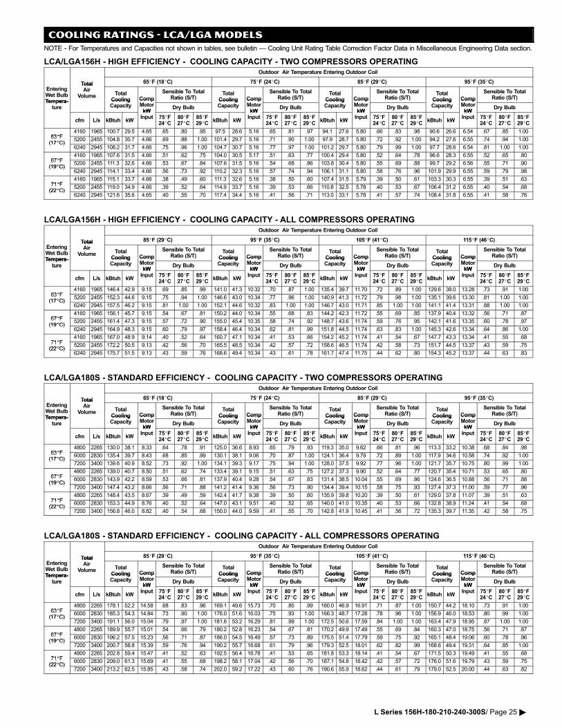
COOLING RATINGS − LCA/LGA MODELS
NOTE − For Temperatures and Capacities not shown in tables, see bulletin � Cooling Unit Rating Table Correction Factor Data in Miscellaneous Engineering Data section.
LCA/LGA156H − HIGH EFFICIENCY − COOLING CAPACITY − TWO COMPRESSORS OPERATINGOutdoor Air Temperature Entering Outdoor Coil
Total 65�F (18�C) 75�F (24�C) 85�F (29�C) 95�F (35�C)
EnteringWet BulbTempera�
TotalAir
Volume TotalCooling Comp
Sensible To TotalRatio (S/T)
TotalCooling Comp
Sensible To TotalRatio (S/T)
TotalCooling Comp
Sensible To TotalRatio (S/T)
TotalCooling Comp
Sensible To TotalRatio (S/T)
Tempera�ture
CoolingCapacity
CompMotorkW
Dry Bulb
CoolingCapacity
CompMotorkW
Dry Bulb
CoolingCapacity
CompMotorkW
Dry Bulb
CoolingCapacity
CompMotorkW
Dry Bulbture
cfm L/s kBtuh kW
kWInput 75�F
24�C80�F27�C
85�F29�C
kBtuh kW
kWInput 75�F
24�C80�F27�C
85�F29�C
kBtuh kW
kWInput 75�F
24�C80�F27�C
85�F29�C
kBtuh kW
kWInput 75�F
24�C80�F27�C
85�F29�C
63�F4160 1965 100.7 29.5 4.65 .65 .80 .95 97.5 28.6 5.16 .65 .81 .97 94.1 27.6 5.80 .66 .83 .98 90.6 26.6 6.54 .67 .85 1.00
63�F(17�C)
5200 2455 104.8 30.7 4.66 .69 .88 1.00 101.4 29.7 5.16 .71 .90 1.00 97.9 28.7 5.80 .72 .92 1.00 94.2 27.6 6.55 .74 .94 1.00(17�C)
6240 2945 108.2 31.7 4.66 .75 .96 1.00 104.7 30.7 5.16 .77 .97 1.00 101.2 29.7 5.80 .79 .99 1.00 97.7 28.6 6.54 .81 1.00 1.00
67�F4160 1965 107.6 31.5 4.66 .51 .62 .75 104.0 30.5 5.17 .51 .63 .77 100.4 29.4 5.80 .52 .64 .78 96.6 28.3 6.55 .52 .65 .80
67�F(19�C)
5200 2455 111.3 32.6 4.66 .53 .67 .84 107.6 31.5 5.16 .54 .68 .86 103.8 30.4 5.80 .55 .69 .88 99.7 29.2 6.56 .55 .71 .90(19�C)
6240 2945 114.1 33.4 4.66 .56 .73 .92 110.2 32.3 5.16 .57 .74 .94 106.1 31.1 5.80 .58 .76 .96 101.9 29.9 6.55 .59 .79 .98
71�F4160 1965 115.1 33.7 4.66 .38 .49 .60 111.3 32.6 5.16 .38 .50 .60 107.4 31.5 5.79 .39 .50 .61 103.3 30.3 6.55 .39 .51 .63
71�F(22�C)
5200 2455 119.0 34.9 4.66 .39 .52 .64 114.9 33.7 5.16 .39 .53 .66 110.8 32.5 5.78 .40 .53 .67 106.4 31.2 6.55 .40 .54 .68(22�C)
6240 2945 121.6 35.6 4.65 .40 .55 .70 117.4 34.4 5.16 .41 .56 .71 113.0 33.1 5.78 .41 .57 .74 108.4 31.8 6.55 .41 .58 .76
LCA/LGA156H − HIGH EFFICIENCY − COOLING CAPACITY − ALL COMPRESSORS OPERATINGOutdoor Air Temperature Entering Outdoor Coil
Total 85�F (29�C) 95�F (35�C) 105�F (41�C) 115�F (46�C)
EnteringWet BulbTempera�
TotalAir
Volume TotalCooling Comp
Sensible To TotalRatio (S/T)
TotalCooling Comp
Sensible To TotalRatio (S/T)
TotalCooling Comp
Sensible To TotalRatio (S/T)
TotalCooling Comp
Sensible To TotalRatio (S/T)
Tempera�ture
CoolingCapacity
CompMotorkW
Dry Bulb
CoolingCapacity
CompMotorkW
Dry Bulb
CoolingCapacity
CompMotorkW
Dry Bulb
CoolingCapacity
CompMotorkW
Dry Bulbture
cfm L/s kBtuh kW
kWInput 75�F
24�C80�F27�C
85�F29�C
kBtuh kW
kWInput 75�F
24�C80�F27�C
85�F29�C
kBtuh kW
kWInput 75�F
24�C80�F27�C
85�F29�C
kBtuh kW
kWInput 75�F
24�C80�F27�C
85�F29�C
63�F4160 1965 146.4 42.9 9.15 .69 .85 .99 141.0 41.3 10.32 .70 .87 1.00 135.4 39.7 11.70 .72 .89 1.00 129.6 38.0 13.28 .73 .91 1.00
63�F(17�C)
5200 2455 152.3 44.6 9.15 .75 .94 1.00 146.6 43.0 10.34 .77 .96 1.00 140.9 41.3 11.72 .79 .98 1.00 135.1 39.6 13.30 .81 1.00 1.00(17�C)
6240 2945 157.5 46.2 9.15 .81 1.00 1.00 152.1 44.6 10.32 .83 1.00 1.00 146.7 43.0 11.71 .85 1.00 1.00 141.1 41.4 13.31 .88 1.00 1.00
67�F4160 1965 156.1 45.7 9.15 .54 .67 .81 150.2 44.0 10.34 .55 .68 .83 144.2 42.3 11.72 .55 .69 .85 137.9 40.4 13.32 .56 .71 .87
67�F(19�C)
5200 2455 161.4 47.3 9.15 .57 .72 .90 155.0 45.4 10.35 .58 .74 .92 148.7 43.6 11.74 .59 .76 .95 142.1 41.6 13.35 .60 .78 .97(19�C)
6240 2945 164.9 48.3 9.15 .60 .79 .97 158.4 46.4 10.34 .62 .81 .99 151.8 44.5 11.74 .63 .83 1.00 145.3 42.6 13.34 .64 .86 1.00
71�F4160 1965 167.0 48.9 9.14 .40 .52 .64 160.7 47.1 10.34 .41 .53 .66 154.2 45.2 11.74 .41 .54 .67 147.7 43.3 13.34 .41 .55 .68
71�F(22�C)
5200 2455 172.2 50.5 9.13 .42 .56 .70 165.5 48.5 10.34 .42 .57 .72 158.6 46.5 11.74 .42 .58 .73 151.7 44.5 13.37 .43 .59 .75(22�C)
6240 2945 175.7 51.5 9.13 .43 .59 .76 168.6 49.4 10.34 .43 .61 .78 161.7 47.4 11.75 .44 .62 .80 154.3 45.2 13.37 .44 .63 .83
LCA/LGA180S − STANDARD EFFICIENCY − COOLING CAPACITY − TWO COMPRESSORS OPERATINGOutdoor Air Temperature Entering Outdoor Coil
Total 65�F (18�C) 75�F (24�C) 85�F (29�C) 95�F (35�C)
EnteringWet BulbTempera�
TotalAir
Volume TotalCooling Comp
Sensible To TotalRatio (S/T)
TotalCooling Comp
Sensible To TotalRatio (S/T)
TotalCooling Comp
Sensible To TotalRatio (S/T)
TotalCooling Comp
Sensible To TotalRatio (S/T)
Tempera�ture
CoolingCapacity
CompMotorkW
Dry Bulb
CoolingCapacity
CompMotorkW
Dry Bulb
CoolingCapacity
CompMotorkW
Dry Bulb
CoolingCapacity
CompMotorkW
Dry Bulbture
cfm L/s kBtuh kW
kWInput 75�F
24�C80�F27�C
85�F29�C
kBtuh kW
kWInput 75�F
24�C80�F27�C
85�F29�C
kBtuh kW
kWInput 75�F
24�C80�F27�C
85�F29�C
kBtuh kW
kWInput 75�F
24�C80�F27�C
85�F29�C
63�F4800 2265 130.0 38.1 8.33 .64 .78 .91 125.0 36.6 8.93 .65 .79 .93 119.3 35.0 9.62 .66 .81 .96 113.3 33.2 10.38 .68 .84 .98
63�F(17�C)
6000 2830 135.4 39.7 8.43 .68 .85 .99 130.1 38.1 9.06 .70 .87 1.00 124.1 36.4 9.79 .72 .89 1.00 117.9 34.6 10.58 .74 .92 1.00(17�C)
7200 3400 139.6 40.9 8.52 .73 .92 1.00 134.1 39.3 9.17 .75 .94 1.00 128.0 37.5 9.92 .77 .96 1.00 121.7 35.7 10.75 .80 .99 1.00
67�F4800 2265 139.0 40.7 8.50 .51 .62 .74 133.4 39.1 9.15 .51 .63 .75 127.2 37.3 9.90 .52 .64 .77 120.7 35.4 10.71 .53 .65 .80
67�F(19�C)
6000 2830 143.9 42.2 8.59 .53 .66 .81 137.9 40.4 9.28 .54 .67 .83 131.4 38.5 10.04 .55 .69 .86 124.6 36.5 10.88 .56 .71 .88(19�C)
7200 3400 147.4 43.2 8.66 .56 .71 .88 141.2 41.4 9.36 .56 .73 .90 134.4 39.4 10.15 .58 .75 .93 127.4 37.3 11.00 .59 .77 .96
71�F4800 2265 148.4 43.5 8.67 .39 .49 .59 142.4 41.7 9.38 .39 .50 .60 135.9 39.8 10.20 .39 .50 .61 129.0 37.8 11.07 .39 .51 .63
71�F(22�C)
6000 2830 153.3 44.9 8.76 .40 .52 .64 147.0 43.1 9.51 .40 .52 .65 140.0 41.0 10.35 .40 .53 .66 132.8 38.9 11.24 .41 .54 .68(22�C)
7200 3400 156.8 46.0 8.82 .40 .54 .68 150.0 44.0 9.59 .41 .55 .70 142.8 41.9 10.45 .41 .56 .72 135.3 39.7 11.35 .42 .58 .75
LCA/LGA180S − STANDARD EFFICIENCY − COOLING CAPACITY − ALL COMPRESSORS OPERATINGOutdoor Air Temperature Entering Outdoor Coil
Total 85�F (29�C) 95�F (35�C) 105�F (41�C) 115�F (46�C)
EnteringWet BulbTempera�
TotalAir
Volume TotalCooling Comp
Sensible To TotalRatio (S/T)
TotalCooling Comp
Sensible To TotalRatio (S/T)
TotalCooling Comp
Sensible To TotalRatio (S/T)
TotalCooling Comp
Sensible To TotalRatio (S/T)
Tempera�ture
CoolingCapacity
CompMotorkW
Dry Bulb
CoolingCapacity
CompMotorkW
Dry Bulb
CoolingCapacity
CompMotorkW
Dry Bulb
CoolingCapacity
CompMotorkW
Dry Bulbture
cfm L/s kBtuh kW
kWInput 75�F
24�C80�F27�C
85�F29�C
kBtuh kW
kWInput 75�F
24�C80�F27�C
85�F29�C
kBtuh kW
kWInput 75�F
24�C80�F27�C
85�F29�C
kBtuh kW
kWInput 75�F
24�C80�F27�C
85�F29�C
63�F4800 2265 178.1 52.2 14.58 .68 .83 .96 169.1 49.6 15.73 .70 .85 .99 160.0 46.9 16.91 .71 .87 1.00 150.7 44.2 18.10 .73 .91 1.00
63�F(17�C)
6000 2830 185.3 54.3 14.84 .73 .90 1.00 176.0 51.6 16.03 .75 .93 1.00 166.3 48.7 17.28 .78 .96 1.00 156.9 46.0 18.53 .80 .99 1.00(17�C)
7200 3400 191.1 56.0 15.04 .79 .97 1.00 181.6 53.2 16.29 .81 .99 1.00 172.5 50.6 17.59 .84 1.00 1.00 163.4 47.9 18.95 .87 1.00 1.00
67�F4800 2265 189.9 55.7 15.01 .54 .66 .79 180.2 52.8 16.23 .54 .67 .81 170.2 49.9 17.49 .55 .69 .84 160.3 47.0 18.75 .56 .71 .87
67�F(19�C)
6000 2830 196.2 57.5 15.23 .56 .71 .87 186.0 54.5 16.49 .57 .73 .89 175.5 51.4 17.79 .59 .75 .92 165.1 48.4 19.06 .60 .78 .96(19�C)
7200 3400 200.7 58.8 15.39 .59 .76 .94 190.2 55.7 16.68 .61 .79 .96 179.3 52.5 18.01 .62 .82 .99 168.6 49.4 19.31 .64 .85 1.00
71�F4800 2265 202.8 59.4 15.47 .41 .52 .63 192.5 56.4 16.78 .41 .53 .65 181.8 53.3 18.14 .41 .54 .67 171.5 50.3 19.49 .41 .55 .68
71�F(22�C)
6000 2830 209.0 61.3 15.69 .41 .55 .68 198.2 58.1 17.04 .42 .56 .70 187.1 54.8 18.42 .42 .57 .72 176.0 51.6 19.79 .43 .59 .75(22�C)
7200 3400 213.2 62.5 15.85 .43 .58 .74 202.0 59.2 17.22 .43 .60 .76 190.6 55.9 18.62 .44 .61 .79 179.0 52.5 20.00 .44 .63 .82
L Series 156H−180−210−240−300S/ Page 25 �
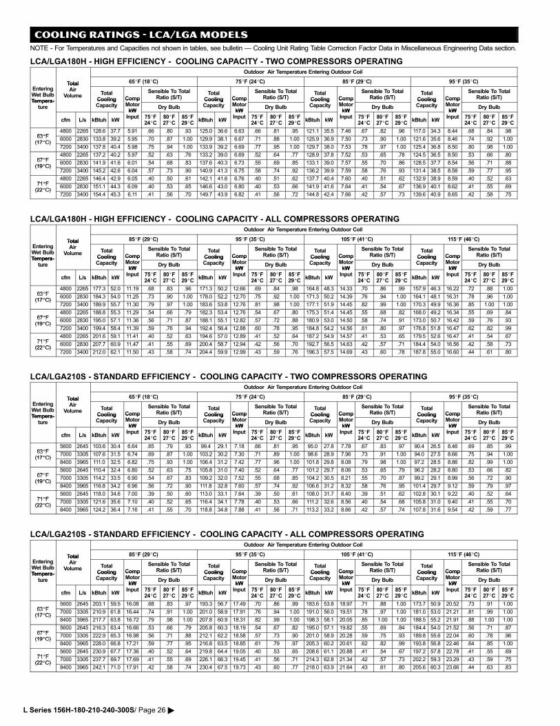
COOLING RATINGS − LCA/LGA MODELS
NOTE − For Temperatures and Capacities not shown in tables, see bulletin � Cooling Unit Rating Table Correction Factor Data in Miscellaneous Engineering Data section.
LCA/LGA180H − HIGH EFFICIENCY − COOLING CAPACITY − TWO COMPRESSORS OPERATINGOutdoor Air Temperature Entering Outdoor Coil
Total 65�F (18�C) 75�F (24�C) 85�F (29�C) 95�F (35�C)
EnteringWet BulbTempera�
TotalAir
Volume TotalCooling Comp
Sensible To TotalRatio (S/T)
TotalCooling Comp
Sensible To TotalRatio (S/T)
TotalCooling Comp
Sensible To TotalRatio (S/T)
TotalCooling Comp
Sensible To TotalRatio (S/T)
Tempera�ture
CoolingCapacity
CompMotorkW
Dry Bulb
CoolingCapacity
CompMotorkW
Dry Bulb
CoolingCapacity
CompMotorkW
Dry Bulb
CoolingCapacity
CompMotorkW
Dry Bulbture
cfm L/s kBtuh kW
kWInput 75�F
24�C80�F27�C
85�F29�C
kBtuh kW
kWInput 75�F
24�C80�F27�C
85�F29�C
kBtuh kW
kWInput 75�F
24�C80�F27�C
85�F29�C
kBtuh kW
kWInput 75�F
24�C80�F27�C
85�F29�C
63�F4800 2265 128.6 37.7 5.91 .66 .80 .93 125.0 36.6 6.63 .66 .81 .95 121.1 35.5 7.46 .67 .82 .96 117.0 34.3 8.44 .68 .84 .98
63�F(17�C)
6000 2830 133.8 39.2 5.95 .70 .87 1.00 129.9 38.1 6.67 .71 .88 1.00 125.9 36.9 7.50 .73 .90 1.00 121.6 35.6 8.46 .74 .92 1.00(17�C)
7200 3400 137.8 40.4 5.98 .75 .94 1.00 133.9 39.2 6.69 .77 .95 1.00 129.7 38.0 7.53 .78 .97 1.00 125.4 36.8 8.50 .80 .98 1.00
67�F4800 2265 137.2 40.2 5.97 .52 .63 .76 133.2 39.0 6.69 .52 .64 .77 128.9 37.8 7.52 .53 .65 .78 124.5 36.5 8.50 .53 .66 .80
67�F(19�C)
6000 2830 141.9 41.6 6.01 .54 .68 .83 137.6 40.3 6.73 .55 .69 .85 133.1 39.0 7.57 .55 .70 .86 128.5 37.7 8.54 .56 .71 .88(19�C)
7200 3400 145.2 42.6 6.04 .57 .73 .90 140.9 41.3 6.75 .58 .74 .92 136.2 39.9 7.59 .58 .76 .93 131.4 38.5 8.58 .59 .77 .95
71�F4800 2265 146.4 42.9 6.05 .40 .50 .61 142.1 41.6 6.76 .40 .51 .62 137.7 40.4 7.60 .40 .51 .62 132.9 38.9 8.59 .40 .52 .63
71�F(22�C)
6000 2830 151.1 44.3 6.09 .40 .53 .65 146.6 43.0 6.80 .40 .53 .66 141.9 41.6 7.64 .41 .54 .67 136.9 40.1 8.62 .41 .55 .69(22�C)
7200 3400 154.4 45.3 6.11 .41 .56 .70 149.7 43.9 6.82 .41 .56 .72 144.8 42.4 7.66 .42 .57 .73 139.6 40.9 8.65 .42 .58 .75
LCA/LGA180H − HIGH EFFICIENCY − COOLING CAPACITY − ALL COMPRESSORS OPERATINGOutdoor Air Temperature Entering Outdoor Coil
Total 85�F (29�C) 95�F (35�C) 105�F (41�C) 115�F (46�C)
EnteringWet BulbTempera�
TotalAir
Volume TotalCooling Comp
Sensible To TotalRatio (S/T)
TotalCooling Comp
Sensible To TotalRatio (S/T)
TotalCooling Comp
Sensible To TotalRatio (S/T)
TotalCooling Comp
Sensible To TotalRatio (S/T)
Tempera�ture
CoolingCapacity
CompMotorkW
Dry Bulb
CoolingCapacity
CompMotorkW
Dry Bulb
CoolingCapacity
CompMotorkW
Dry Bulb
CoolingCapacity
CompMotorkW
Dry Bulbture
cfm L/s kBtuh kW
kWInput 75�F
24�C80�F27�C
85�F29�C
kBtuh kW
kWInput 75�F
24�C80�F27�C
85�F29�C
kBtuh kW
kWInput 75�F
24�C80�F27�C
85�F29�C
kBtuh kW
kWInput 75�F
24�C80�F27�C
85�F29�C
63�F4800 2265 177.3 52.0 11.19 .68 .83 .96 171.3 50.2 12.66 .69 .84 .98 164.8 48.3 14.33 .70 .86 .99 157.9 46.3 16.22 .72 .88 1.00
63�F(17�C)
6000 2830 184.3 54.0 11.25 .73 .90 1.00 178.0 52.2 12.70 .75 .92 1.00 171.3 50.2 14.39 .76 .94 1.00 164.1 48.1 16.31 .78 .96 1.00(17�C)
7200 3400 189.9 55.7 11.30 .79 .97 1.00 183.6 53.8 12.76 .81 .98 1.00 177.1 51.9 14.45 .82 .99 1.00 170.3 49.9 16.36 .85 1.00 1.00
67�F4800 2265 188.8 55.3 11.29 .54 .66 .79 182.3 53.4 12.76 .54 .67 .80 175.3 51.4 14.45 .55 .68 .82 168.0 49.2 16.34 .55 .69 .84
67�F(19�C)
6000 2830 195.0 57.1 11.36 .56 .71 .87 188.1 55.1 12.82 .57 .72 .88 180.9 53.0 14.50 .58 .74 .91 173.0 50.7 16.42 .59 .76 .93(19�C)
7200 3400 199.4 58.4 11.39 .59 .76 .94 192.4 56.4 12.88 .60 .78 .95 184.8 54.2 14.56 .61 .80 .97 176.8 51.8 16.47 .62 .82 .99
71�F4800 2265 201.6 59.1 11.41 .40 .52 .63 194.6 57.0 12.89 .41 .52 .64 187.2 54.9 14.57 .41 .53 .65 179.5 52.6 16.47 .41 .54 .67
71�F(22�C)
6000 2830 207.7 60.9 11.47 .41 .55 .69 200.4 58.7 12.94 .42 .56 .70 192.7 56.5 14.63 .42 .57 .71 184.4 54.0 16.56 .42 .58 .73(22�C)
7200 3400 212.0 62.1 11.50 .43 .58 .74 204.4 59.9 12.99 .43 .59 .76 196.3 57.5 14.69 .43 .60 .78 187.8 55.0 16.60 .44 .61 .80
LCA/LGA210S − STANDARD EFFICIENCY − COOLING CAPACITY − TWO COMPRESSORS OPERATINGOutdoor Air Temperature Entering Outdoor Coil
Total 65�F (18�C) 75�F (24�C) 85�F (29�C) 95�F (35�C)
EnteringWet BulbTempera�
TotalAir
Volume TotalCooling Comp
Sensible To TotalRatio (S/T)
TotalCooling Comp
Sensible To TotalRatio (S/T)
TotalCooling Comp
Sensible To TotalRatio (S/T)
TotalCooling Comp
Sensible To TotalRatio (S/T)
Tempera�ture
CoolingCapacity
CompMotorkW
Dry Bulb
CoolingCapacity
CompMotorkW
Dry Bulb
CoolingCapacity
CompMotorkW
Dry Bulb
CoolingCapacity
CompMotorkW
Dry Bulbture
cfm L/s kBtuh kW
kWInput 75�F
24�C80�F27�C
85�F29�C
kBtuh kW
kWInput 75�F
24�C80�F27�C
85�F29�C
kBtuh kW
kWInput 75�F
24�C80�F27�C
85�F29�C
kBtuh kW
kWInput 75�F
24�C80�F27�C
85�F29�C
63�F5600 2645 103.6 30.4 6.64 .65 .79 .93 99.4 29.1 7.18 .66 .81 .95 95.0 27.8 7.78 .67 .83 .97 90.4 26.5 8.46 .69 .85 .99
63�F(17�C)
7000 3305 107.6 31.5 6.74 .69 .87 1.00 103.2 30.2 7.30 .71 .89 1.00 98.6 28.9 7.96 .73 .91 1.00 94.0 27.5 8.66 .75 .94 1.00(17�C)
8400 3965 111.0 32.5 6.82 .75 .93 1.00 106.4 31.2 7.42 .77 .96 1.00 101.8 29.8 8.08 .79 .98 1.00 97.2 28.5 8.86 .82 .99 1.00
67�F5600 2645 110.4 32.4 6.80 .52 .63 .75 105.8 31.0 7.40 .52 .64 .77 101.2 29.7 8.06 .53 .65 .79 96.2 28.2 8.80 .53 .66 .82
67�F(19�C)
7000 3305 114.2 33.5 6.90 .54 .67 .83 109.2 32.0 7.52 .55 .68 .85 104.2 30.5 8.21 .55 .70 .87 99.2 29.1 8.99 .56 .72 .90(19�C)
8400 3965 116.8 34.2 6.96 .56 .72 .90 111.8 32.8 7.60 .57 .74 .92 106.6 31.2 8.32 .58 .76 .95 101.4 29.7 9.12 .59 .79 .97
71�F5600 2645 118.0 34.6 7.00 .39 .50 .60 113.0 33.1 7.64 .39 .50 .61 108.0 31.7 8.40 .39 .51 .62 102.8 30.1 9.22 .40 .52 .64
71�F(22�C)
7000 3305 121.6 35.6 7.10 .40 .52 .65 116.4 34.1 7.78 .40 .53 .66 111.2 32.6 8.56 .40 .54 .68 105.8 31.0 9.40 .41 .55 .70(22�C)
8400 3965 124.2 36.4 7.16 .41 .55 .70 118.8 34.8 7.88 .41 .56 .71 113.2 33.2 8.66 .42 .57 .74 107.8 31.6 9.54 .42 .59 .77
LCA/LGA210S − STANDARD EFFICIENCY − COOLING CAPACITY − ALL COMPRESSORS OPERATINGOutdoor Air Temperature Entering Outdoor Coil
Total 85�F (29�C) 95�F (35�C) 105�F (41�C) 115�F (46�C)
EnteringWet BulbTempera�
TotalAir
Volume TotalCooling Comp
Sensible To TotalRatio (S/T)
TotalCooling Comp
Sensible To TotalRatio (S/T)
TotalCooling Comp
Sensible To TotalRatio (S/T)
TotalCooling Comp
Sensible To TotalRatio (S/T)
Tempera�ture
CoolingCapacity
CompMotorkW
Dry Bulb
CoolingCapacity
CompMotorkW
Dry Bulb
CoolingCapacity
CompMotorkW
Dry Bulb
CoolingCapacity
CompMotorkW
Dry Bulbture
cfm L/s kBtuh kW
kWInput 75�F
24�C80�F27�C
85�F29�C
kBtuh kW
kWInput 75�F
24�C80�F27�C
85�F29�C
kBtuh kW
kWInput 75�F
24�C80�F27�C
85�F29�C
kBtuh kW
kWInput 75�F
24�C80�F27�C
85�F29�C
63�F5600 2645 203.1 59.5 16.08 .68 .83 .97 193.3 56.7 17.49 .70 .86 .99 183.6 53.8 18.97 .71 .88 1.00 173.7 50.9 20.52 .73 .91 1.00
63�F(17�C)
7000 3305 210.9 61.8 16.44 .74 .91 1.00 201.0 58.9 17.91 .76 .94 1.00 191.0 56.0 19.51 .78 .97 1.00 181.0 53.0 21.21 .81 .99 1.00(17�C)
8400 3965 217.7 63.8 16.72 .79 .98 1.00 207.8 60.9 18.31 .82 .99 1.00 198.3 58.1 20.05 .85 1.00 1.00 188.5 55.2 21.91 .88 1.00 1.00
67�F5600 2645 216.3 63.4 16.66 .53 .66 .79 205.8 60.3 18.19 .54 .67 .82 195.0 57.1 19.82 .55 .69 .84 184.4 54.0 21.52 .56 .71 .87
67�F(19�C)
7000 3305 222.9 65.3 16.98 .56 .71 .88 212.1 62.2 18.58 .57 .73 .90 201.0 58.9 20.28 .59 .75 .93 189.8 55.6 22.04 .60 .78 .96(19�C)
8400 3965 228.0 66.8 17.21 .59 .77 .95 216.8 63.5 18.85 .61 .79 .97 205.3 60.2 20.61 .62 .82 .99 193.8 56.8 22.46 .64 .85 1.00
71�F5600 2645 230.9 67.7 17.36 .40 .52 .64 219.8 64.4 19.05 .40 .53 .65 208.6 61.1 20.88 .41 .54 .67 197.2 57.8 22.78 .41 .55 .69
71�F(22�C)
7000 3305 237.7 69.7 17.69 .41 .55 .69 226.1 66.3 19.45 .41 .56 .71 214.3 62.8 21.34 .42 .57 .73 202.2 59.3 23.29 .43 .59 .75(22�C)
8400 3965 242.1 71.0 17.91 .42 .58 .74 230.4 67.5 19.73 .43 .60 .77 218.0 63.9 21.64 .43 .61 .80 205.6 60.3 23.66 .44 .63 .83
L Series 156H−180−210−240−300S/ Page 26 �
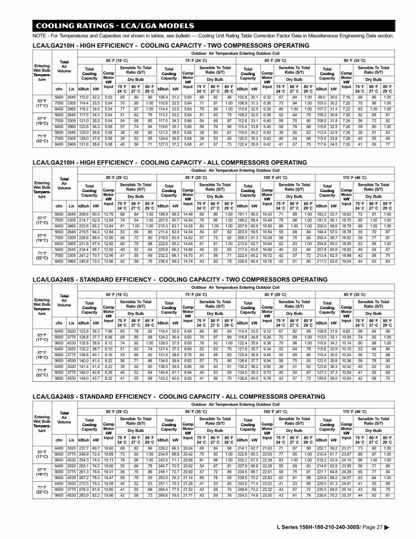
COOLING RATINGS − LCA/LGA MODELS
NOTE − For Temperatures and Capacities not shown in tables, see bulletin � Cooling Unit Rating Table Correction Factor Data in Miscellaneous Engineering Data section.
LCA/LGA210H − HIGH EFFICIENCY − COOLING CAPACITY − TWO COMPRESSORS OPERATINGOutdoor Air Temperature Entering Outdoor Coil
Total 65�F (18�C) 75�F (24�C) 85�F (29�C) 95�F (35�C)
EnteringWet BulbTempera�
TotalAir
Volume TotalCooling Comp
Sensible To TotalRatio (S/T)
TotalCooling Comp
Sensible To TotalRatio (S/T)
TotalCooling Comp
Sensible To TotalRatio (S/T)
TotalCooling Comp
Sensible To TotalRatio (S/T)
Tempera�ture
CoolingCapacity
CompMotorkW
Dry Bulb
CoolingCapacity
CompMotorkW
Dry Bulb
CoolingCapacity
CompMotorkW
Dry Bulb
CoolingCapacity
CompMotorkW
Dry Bulbture
cfm L/s kBtuh kW
kWInput 75�F
24�C80�F27�C
85�F29�C
kBtuh kW
kWInput 75�F
24�C80�F27�C
85�F29�C
kBtuh kW
kWInput 75�F
24�C80�F27�C
85�F29�C
kBtuh kW
kWInput 75�F
24�C80�F27�C
85�F29�C
63�F5600 2645 110.0 32.2 5.02 .65 .80 .96 106.4 31.2 5.60 .66 .82 .98 102.8 30.1 6.32 .67 .84 1.00 99.0 29.0 7.16 .68 .86 1.00
63�F(17�C)
7000 3305 114.4 33.5 5.04 .70 .90 1.00 110.8 32.5 5.64 .71 .91 1.00 106.9 31.3 6.36 .73 .94 1.00 103.0 30.2 7.20 .75 .96 1.00(17�C)
8400 3965 118.2 34.6 5.04 .77 .97 1.00 114.4 33.5 5.64 .79 .99 1.00 110.8 32.5 6.36 .80 1.00 1.00 107.2 31.4 7.22 .83 1.00 1.00
67�F5600 2645 117.0 34.3 5.04 .51 .62 .76 113.2 33.2 5.64 .51 .63 .78 109.2 32.0 6.36 .52 .64 .79 105.2 30.8 7.20 .52 .65 .81
67�F(19�C)
7000 3305 121.0 35.5 5.04 .54 .68 .85 117.0 34.3 5.66 .54 .69 .87 112.8 33.1 6.40 .55 .70 .90 108.5 31.8 7.24 .56 .72 .92(19�C)
8400 3965 123.8 36.3 5.06 .57 .74 .94 119.6 35.1 5.66 .58 .76 .96 115.4 33.8 6.40 .58 .78 .98 110.8 32.5 7.26 .59 .80 1.00
71�F5600 2645 125.0 36.6 5.06 .38 .49 .60 121.0 35.5 5.66 .38 .50 .61 116.6 34.2 6.40 .39 .50 .62 112.4 32.9 7.26 .39 .51 .63
71�F(22�C)
7000 3305 129.0 37.8 5.06 .39 .52 .65 124.6 36.5 5.68 .39 .53 .66 120.0 35.2 6.42 .40 .54 .68 115.6 33.9 7.28 .40 .55 .69(22�C)
8400 3965 131.6 38.6 5.08 .40 .56 .71 127.0 37.2 5.68 .41 .57 .73 122.4 35.9 6.42 .41 .57 .75 117.6 34.5 7.30 .41 .59 .77
LCA/LGA210H − HIGH EFFICIENCY − COOLING CAPACITY − ALL COMPRESSORS OPERATINGOutdoor Air Temperature Entering Outdoor Coil
Total 85�F (29�C) 95�F (35�C) 105�F (41�C) 115�F (46�C)
EnteringWet BulbTempera�
TotalAir
Volume TotalCooling Comp
Sensible To TotalRatio (S/T)
TotalCooling Comp
Sensible To TotalRatio (S/T)
TotalCooling Comp
Sensible To TotalRatio (S/T)
TotalCooling Comp
Sensible To TotalRatio (S/T)
Tempera�ture
CoolingCapacity
CompMotorkW
Dry Bulb
CoolingCapacity
CompMotorkW
Dry Bulb
CoolingCapacity
CompMotorkW
Dry Bulb
CoolingCapacity
CompMotorkW
Dry Bulbture
cfm L/s kBtuh kW
kWInput 75�F
24�C80�F27�C
85�F29�C
kBtuh kW
kWInput 75�F
24�C80�F27�C
85�F29�C
kBtuh kW
kWInput 75�F
24�C80�F27�C
85�F29�C
kBtuh kW
kWInput 75�F
24�C80�F27�C
85�F29�C
63�F5600 2645 206.6 60.5 12.76 .68 .84 1.00 198.9 58.3 14.46 .69 .86 1.00 191.1 56.0 16.42 .71 .89 1.00 183.2 53.7 18.62 .72 .91 1.00
63�F(17�C)
7000 3305 214.7 62.9 12.84 .74 .94 1.00 207.0 60.7 14.54 .76 .96 1.00 199.2 58.4 16.48 .78 .98 1.00 191.5 56.1 18.70 .80 1.00 1.00(17�C)
8400 3965 222.6 65.2 12.84 .81 1.00 1.00 215.3 63.1 14.58 .83 1.00 1.00 207.8 60.9 16.56 .86 1.00 1.00 200.0 58.6 18.78 .88 1.00 1.00
67�F5600 2645 219.5 64.3 12.84 .53 .66 .80 211.4 62.0 14.54 .54 .67 .82 203.0 59.5 16.54 .55 .68 .84 194.4 57.0 18.78 .55 .70 .87
67�F(19�C)
7000 3305 226.6 66.4 12.90 .56 .72 .90 218.0 63.9 14.62 .57 .73 .92 209.3 61.3 16.58 .58 .75 .95 200.4 58.7 18.82 .59 .77 .97(19�C)
8400 3965 231.8 67.9 12.92 .60 .78 .98 222.6 65.2 14.64 .61 .81 1.00 213.8 62.7 16.64 .62 .83 1.00 204.8 60.0 18.90 .63 .86 1.00
71�F5600 2645 234.4 68.7 12.92 .40 .52 .64 225.8 66.2 14.66 .40 .52 .65 217.0 63.6 16.66 .40 .53 .66 207.8 60.9 18.92 .40 .54 .67
71�F(22�C)
7000 3305 241.2 70.7 12.96 .41 .55 .69 232.2 68.1 14.70 .41 .56 .71 222.6 65.2 16.72 .42 .57 .72 213.4 62.5 18.98 .42 .58 .75(22�C)
8400 3965 245.8 72.0 12.96 .42 .59 .76 236.4 69.3 14.74 .43 .60 .78 226.6 66.4 16.76 .43 .61 .80 217.0 63.6 19.04 .44 .63 .83
LCA/LGA240S − STANDARD EFFICIENCY − COOLING CAPACITY − TWO COMPRESSORS OPERATINGOutdoor Air Temperature Entering Outdoor Coil
Total 65�F (18�C) 75�F (24�C) 85�F (29�C) 95�F (35�C)
EnteringWet BulbTempera�
TotalAir
Volume TotalCooling Comp
Sensible To TotalRatio (S/T)
TotalCooling Comp
Sensible To TotalRatio (S/T)
TotalCooling Comp
Sensible To TotalRatio (S/T)
TotalCooling Comp
Sensible To TotalRatio (S/T)
Tempera�ture
CoolingCapacity
CompMotorkW
Dry Bulb
CoolingCapacity
CompMotorkW
Dry Bulb
CoolingCapacity
CompMotorkW
Dry Bulb
CoolingCapacity
CompMotorkW
Dry Bulbture
cfm L/s kBtuh kW
kWInput 75�F
24�C80�F27�C
85�F29�C
kBtuh kW
kWInput 75�F
24�C80�F27�C
85�F29�C
kBtuh kW
kWInput 75�F
24�C80�F27�C
85�F29�C
kBtuh kW
kWInput 75�F
24�C80�F27�C
85�F29�C
63�F6400 3020 123.8 36.3 7.98 .65 .78 .92 119.4 35.0 8.48 .66 .80 .94 114.4 33.5 9.12 .67 .82 .95 108.8 31.9 9.82 .68 .84 .98
63�F(17�C)
8000 3775 128.8 37.7 8.06 .69 .85 .98 124.2 36.4 8.60 .70 .87 .99 118.8 34.8 9.26 .72 .89 1.00 113.0 33.1 10.00 .74 .92 1.00(17�C)
9600 4530 132.8 38.9 8.12 .74 .92 1.00 128.0 37.5 8.68 .76 .93 1.00 122.4 35.9 9.38 .78 .96 1.00 116.8 34.2 10.14 .80 .98 1.00
67�F6400 3020 132.2 38.7 8.10 .51 .62 .74 127.4 37.3 8.66 .52 .63 .76 121.8 35.7 9.34 .52 .64 .78 115.8 33.9 10.10 .53 .66 .80
67�F(19�C)
8000 3775 136.8 40.1 8.16 .53 .66 .82 131.6 38.6 8.76 .54 .68 .83 125.8 36.9 9.46 .55 .69 .86 119.4 35.0 10.24 .56 .72 .88(19�C)
9600 4530 140.0 41.0 8.22 .56 .71 .88 134.6 39.4 8.82 .57 .73 .90 128.6 37.7 9.54 .58 .75 .93 122.0 35.8 10.36 .59 .78 .95
71�F6400 3020 141.4 41.4 8.22 .39 .50 .60 136.0 39.9 8.86 .39 .50 .61 130.2 38.2 9.60 .39 .51 .62 123.8 36.3 10.42 .40 .52 .63
71�F(22�C)
8000 3775 146.0 42.8 8.28 .40 .52 .64 140.4 41.1 8.94 .40 .53 .65 134.0 39.3 9.70 .40 .54 .67 127.2 37.3 10.54 .41 .55 .69(22�C)
9600 4530 149.0 43.7 8.32 .41 .55 .69 143.2 42.0 9.00 .41 .56 .70 136.6 40.0 9.78 .42 .57 .72 129.8 38.0 10.64 .42 .58 .75
LCA/LGA240S − STANDARD EFFICIENCY − COOLING CAPACITY − ALL COMPRESSORS OPERATINGOutdoor Air Temperature Entering Outdoor Coil
Total 85�F (29�C) 95�F (35�C) 105�F (41�C) 115�F (46�C)
EnteringWet BulbTempera�
TotalAir
Volume TotalCooling Comp
Sensible To TotalRatio (S/T)
TotalCooling Comp
Sensible To TotalRatio (S/T)
TotalCooling Comp
Sensible To TotalRatio (S/T)
TotalCooling Comp
Sensible To TotalRatio (S/T)
Tempera�ture
CoolingCapacity
CompMotorkW
Dry Bulb
CoolingCapacity
CompMotorkW
Dry Bulb
CoolingCapacity
CompMotorkW
Dry Bulb
CoolingCapacity
CompMotorkW
Dry Bulbture
cfm L/s kBtuh kW
kWInput 75�F
24�C80�F27�C
85�F29�C
kBtuh kW
kWInput 75�F
24�C80�F27�C
85�F29�C
kBtuh kW
kWInput 75�F
24�C80�F27�C
85�F29�C
kBtuh kW
kWInput 75�F
24�C80�F27�C
85�F29�C
63�F6400 3020 237.7 69.7 18.60 .68 .82 .96 226.2 66.3 20.04 .69 .84 .98 214.1 62.7 21.63 .71 .87 .99 202.1 59.2 23.21 .73 .90 1.00
63�F(17�C)
8000 3775 246.9 72.4 18.89 .73 .90 1.00 234.9 68.8 20.42 .75 .92 1.00 222.8 65.3 22.03 .77 .95 1.00 210.4 61.7 23.67 .80 .97 1.00(17�C)
9600 4530 254.3 74.5 19.13 .78 .96 1.00 242.5 71.1 20.68 .81 .98 1.00 230.2 67.5 22.39 .83 1.00 1.00 218.2 63.9 24.15 .86 1.00 1.00
67�F6400 3020 253.1 74.2 19.06 .53 .66 .78 240.7 70.5 20.62 .54 .67 .81 227.9 66.8 22.28 .55 .69 .83 214.6 62.9 23.95 .56 .71 .86
67�F(19�C)
8000 3775 261.3 76.6 19.31 .56 .70 .86 248.1 72.7 20.90 .57 .72 .89 234.5 68.7 22.61 .58 .75 .91 221.1 64.8 24.29 .60 .77 .94(19�C)
9600 4530 267.2 78.3 19.47 .59 .76 .93 253.5 74.3 21.14 .60 .78 .95 239.5 70.2 22.83 .62 .81 .98 225.8 66.2 24.57 .63 .84 1.00
71�F6400 3020 270.5 79.3 19.58 .40 .52 .63 257.1 75.3 21.26 .41 .53 .65 243.5 71.4 23.02 .41 .53 .66 229.5 67.3 24.81 .41 .55 .68
71�F(22�C)
8000 3775 278.3 81.6 19.80 .41 .55 .68 264.4 77.5 21.52 .42 .56 .70 249.9 73.2 23.32 .42 .57 .72 235.5 69.0 25.14 .43 .59 .75(22�C)
9600 4530 283.9 83.2 19.96 .42 .58 .73 269.6 79.0 21.71 .43 .59 .76 254.5 74.6 23.55 .43 .61 .78 239.6 70.2 25.37 .44 .62 .81
L Series 156H−180−210−240−300S/ Page 27 �
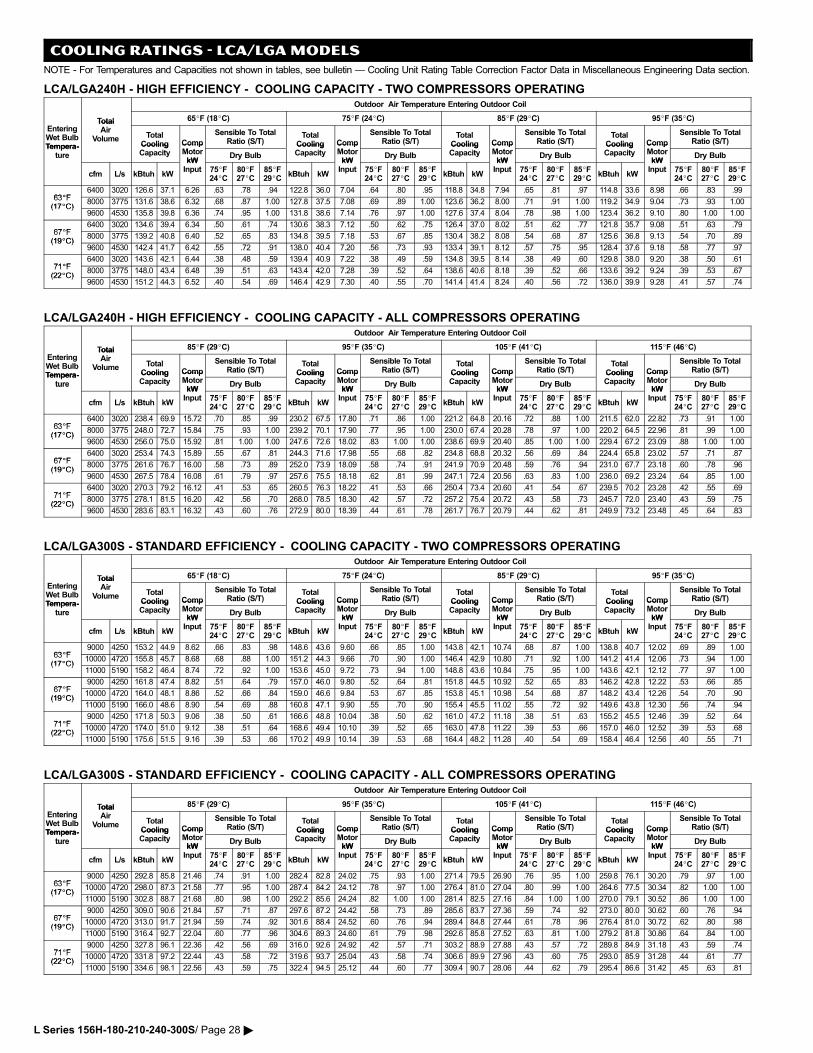
COOLING RATINGS − LCA/LGA MODELS
NOTE − For Temperatures and Capacities not shown in tables, see bulletin � Cooling Unit Rating Table Correction Factor Data in Miscellaneous Engineering Data section.
LCA/LGA240H − HIGH EFFICIENCY − COOLING CAPACITY − TWO COMPRESSORS OPERATINGOutdoor Air Temperature Entering Outdoor Coil
Total 65�F (18�C) 75�F (24�C) 85�F (29�C) 95�F (35�C)
EnteringWet BulbTempera�
TotalAir
Volume TotalCooling Comp
Sensible To TotalRatio (S/T)
TotalCooling Comp
Sensible To TotalRatio (S/T)
TotalCooling Comp
Sensible To TotalRatio (S/T)
TotalCooling Comp
Sensible To TotalRatio (S/T)
Tempera�ture
CoolingCapacity
CompMotorkW
Dry Bulb
CoolingCapacity
CompMotorkW
Dry Bulb
CoolingCapacity
CompMotorkW
Dry Bulb
CoolingCapacity
CompMotorkW
Dry Bulbture
cfm L/s kBtuh kW
kWInput 75�F
24�C80�F27�C
85�F29�C
kBtuh kW
kWInput 75�F
24�C80�F27�C
85�F29�C
kBtuh kW
kWInput 75�F
24�C80�F27�C
85�F29�C
kBtuh kW
kWInput 75�F
24�C80�F27�C
85�F29�C
63�F6400 3020 126.6 37.1 6.26 .63 .78 .94 122.8 36.0 7.04 .64 .80 .95 118.8 34.8 7.94 .65 .81 .97 114.8 33.6 8.98 .66 .83 .99
63�F(17�C)
8000 3775 131.6 38.6 6.32 .68 .87 1.00 127.8 37.5 7.08 .69 .89 1.00 123.6 36.2 8.00 .71 .91 1.00 119.2 34.9 9.04 .73 .93 1.00(17�C)
9600 4530 135.8 39.8 6.36 .74 .95 1.00 131.8 38.6 7.14 .76 .97 1.00 127.6 37.4 8.04 .78 .98 1.00 123.4 36.2 9.10 .80 1.00 1.00
67�F6400 3020 134.6 39.4 6.34 .50 .61 .74 130.6 38.3 7.12 .50 .62 .75 126.4 37.0 8.02 .51 .62 .77 121.8 35.7 9.08 .51 .63 .79
67�F(19�C)
8000 3775 139.2 40.8 6.40 .52 .65 .83 134.8 39.5 7.18 .53 .67 .85 130.4 38.2 8.08 .54 .68 .87 125.6 36.8 9.13 .54 .70 .89(19�C)
9600 4530 142.4 41.7 6.42 .55 .72 .91 138.0 40.4 7.20 .56 .73 .93 133.4 39.1 8.12 .57 .75 .95 128.4 37.6 9.18 .58 .77 .97
71�F6400 3020 143.6 42.1 6.44 .38 .48 .59 139.4 40.9 7.22 .38 .49 .59 134.8 39.5 8.14 .38 .49 .60 129.8 38.0 9.20 .38 .50 .61
71�F(22�C)
8000 3775 148.0 43.4 6.48 .39 .51 .63 143.4 42.0 7.28 .39 .52 .64 138.6 40.6 8.18 .39 .52 .66 133.6 39.2 9.24 .39 .53 .67(22�C)
9600 4530 151.2 44.3 6.52 .40 .54 .69 146.4 42.9 7.30 .40 .55 .70 141.4 41.4 8.24 .40 .56 .72 136.0 39.9 9.28 .41 .57 .74
LCA/LGA240H − HIGH EFFICIENCY − COOLING CAPACITY − ALL COMPRESSORS OPERATINGOutdoor Air Temperature Entering Outdoor Coil
Total 85�F (29�C) 95�F (35�C) 105�F (41�C) 115�F (46�C)
EnteringWet BulbTempera�
TotalAir
Volume TotalCooling Comp
Sensible To TotalRatio (S/T)
TotalCooling Comp
Sensible To TotalRatio (S/T)
TotalCooling Comp
Sensible To TotalRatio (S/T)
TotalCooling Comp
Sensible To TotalRatio (S/T)
Tempera�ture
CoolingCapacity
CompMotorkW
Dry Bulb
CoolingCapacity
CompMotorkW
Dry Bulb
CoolingCapacity
CompMotorkW
Dry Bulb
CoolingCapacity
CompMotorkW
Dry Bulbture
cfm L/s kBtuh kW
kWInput 75�F
24�C80�F27�C
85�F29�C
kBtuh kW
kWInput 75�F
24�C80�F27�C
85�F29�C
kBtuh kW
kWInput 75�F
24�C80�F27�C
85�F29�C
kBtuh kW
kWInput 75�F
24�C80�F27�C
85�F29�C
63�F6400 3020 238.4 69.9 15.72 .70 .85 .99 230.2 67.5 17.80 .71 .86 1.00 221.2 64.8 20.16 .72 .88 1.00 211.5 62.0 22.82 .73 .91 1.00
63�F(17�C)
8000 3775 248.0 72.7 15.84 .75 .93 1.00 239.2 70.1 17.90 .77 .95 1.00 230.0 67.4 20.28 .78 .97 1.00 220.2 64.5 22.96 .81 .99 1.00(17�C)
9600 4530 256.0 75.0 15.92 .81 1.00 1.00 247.6 72.6 18.02 .83 1.00 1.00 238.6 69.9 20.40 .85 1.00 1.00 229.4 67.2 23.09 .88 1.00 1.00
67�F6400 3020 253.4 74.3 15.89 .55 .67 .81 244.3 71.6 17.98 .55 .68 .82 234.8 68.8 20.32 .56 .69 .84 224.4 65.8 23.02 .57 .71 .87
67�F(19�C)
8000 3775 261.6 76.7 16.00 .58 .73 .89 252.0 73.9 18.09 .58 .74 .91 241.9 70.9 20.48 .59 .76 .94 231.0 67.7 23.18 .60 .78 .96(19�C)
9600 4530 267.5 78.4 16.08 .61 .79 .97 257.6 75.5 18.18 .62 .81 .99 247.1 72.4 20.56 .63 .83 1.00 236.0 69.2 23.24 .64 .85 1.00
71�F6400 3020 270.3 79.2 16.12 .41 .53 .65 260.5 76.3 18.22 .41 .53 .66 250.4 73.4 20.60 .41 .54 .67 239.5 70.2 23.28 .42 .55 .69
71�F(22�C)
8000 3775 278.1 81.5 16.20 .42 .56 .70 268.0 78.5 18.30 .42 .57 .72 257.2 75.4 20.72 .43 .58 .73 245.7 72.0 23.40 .43 .59 .75(22�C)
9600 4530 283.6 83.1 16.32 .43 .60 .76 272.9 80.0 18.39 .44 .61 .78 261.7 76.7 20.79 .44 .62 .81 249.9 73.2 23.48 .45 .64 .83
LCA/LGA300S − STANDARD EFFICIENCY − COOLING CAPACITY − TWO COMPRESSORS OPERATINGOutdoor Air Temperature Entering Outdoor Coil
Total 65�F (18�C) 75�F (24�C) 85�F (29�C) 95�F (35�C)
EnteringWet BulbTempera�
TotalAir
Volume TotalCooling Comp
Sensible To TotalRatio (S/T)
TotalCooling Comp
Sensible To TotalRatio (S/T)
TotalCooling Comp
Sensible To TotalRatio (S/T)
TotalCooling Comp
Sensible To TotalRatio (S/T)
Tempera�ture
CoolingCapacity
CompMotorkW
Dry Bulb
CoolingCapacity
CompMotorkW
Dry Bulb
CoolingCapacity
CompMotorkW
Dry Bulb
CoolingCapacity
CompMotorkW
Dry Bulbture
cfm L/s kBtuh kW
kWInput 75�F
24�C80�F27�C
85�F29�C
kBtuh kW
kWInput 75�F
24�C80�F27�C
85�F29�C
kBtuh kW
kWInput 75�F
24�C80�F27�C
85�F29�C
kBtuh kW
kWInput 75�F
24�C80�F27�C
85�F29�C
63�F9000 4250 153.2 44.9 8.62 .66 .83 .98 148.6 43.6 9.60 .66 .85 1.00 143.8 42.1 10.74 .68 .87 1.00 138.8 40.7 12.02 .69 .89 1.00
63�F(17�C)
10000 4720 155.8 45.7 8.68 .68 .88 1.00 151.2 44.3 9.66 .70 .90 1.00 146.4 42.9 10.80 .71 .92 1.00 141.2 41.4 12.06 .73 .94 1.00(17�C)
11000 5190 158.2 46.4 8.74 .72 .92 1.00 153.6 45.0 9.72 .73 .94 1.00 148.8 43.6 10.84 .75 .95 1.00 143.6 42.1 12.12 .77 .97 1.00
67�F9000 4250 161.8 47.4 8.82 .51 .64 .79 157.0 46.0 9.80 .52 .64 .81 151.8 44.5 10.92 .52 .65 .83 146.2 42.8 12.22 .53 .66 .85
67�F(19�C)
10000 4720 164.0 48.1 8.86 .52 .66 .84 159.0 46.6 9.84 .53 .67 .85 153.8 45.1 10.98 .54 .68 .87 148.2 43.4 12.26 .54 .70 .90(19�C)
11000 5190 166.0 48.6 8.90 .54 .69 .88 160.8 47.1 9.90 .55 .70 .90 155.4 45.5 11.02 .55 .72 .92 149.6 43.8 12.30 .56 .74 .94
71�F9000 4250 171.8 50.3 9.06 .38 .50 .61 166.6 48.8 10.04 .38 .50 .62 161.0 47.2 11.18 .38 .51 .63 155.2 45.5 12.46 .39 .52 .64
71�F(22�C)
10000 4720 174.0 51.0 9.12 .38 .51 .64 168.6 49.4 10.10 .39 .52 .65 163.0 47.8 11.22 .39 .53 .66 157.0 46.0 12.52 .39 .53 .68(22�C)
11000 5190 175.6 51.5 9.16 .39 .53 .66 170.2 49.9 10.14 .39 .53 .68 164.4 48.2 11.28 .40 .54 .69 158.4 46.4 12.56 .40 .55 .71
LCA/LGA300S − STANDARD EFFICIENCY − COOLING CAPACITY − ALL COMPRESSORS OPERATINGOutdoor Air Temperature Entering Outdoor Coil
Total 85�F (29�C) 95�F (35�C) 105�F (41�C) 115�F (46�C)
EnteringWet BulbTempera�
TotalAir
Volume TotalCooling Comp
Sensible To TotalRatio (S/T)
TotalCooling Comp
Sensible To TotalRatio (S/T)
TotalCooling Comp
Sensible To TotalRatio (S/T)
TotalCooling Comp
Sensible To TotalRatio (S/T)
Tempera�ture
CoolingCapacity
CompMotorkW
Dry Bulb
CoolingCapacity
CompMotorkW
Dry Bulb
CoolingCapacity
CompMotorkW
Dry Bulb
CoolingCapacity
CompMotorkW
Dry Bulbture
cfm L/s kBtuh kW
kWInput 75�F
24�C80�F27�C
85�F29�C
kBtuh kW
kWInput 75�F
24�C80�F27�C
85�F29�C
kBtuh kW
kWInput 75�F
24�C80�F27�C
85�F29�C
kBtuh kW
kWInput 75�F
24�C80�F27�C
85�F29�C
63�F9000 4250 292.8 85.8 21.46 .74 .91 1.00 282.4 82.8 24.02 .75 .93 1.00 271.4 79.5 26.90 .76 .95 1.00 259.8 76.1 30.20 .79 .97 1.00
63�F(17�C)
10000 4720 298.0 87.3 21.58 .77 .95 1.00 287.4 84.2 24.12 .78 .97 1.00 276.4 81.0 27.04 .80 .99 1.00 264.6 77.5 30.34 .82 1.00 1.00(17�C)
11000 5190 302.8 88.7 21.68 .80 .98 1.00 292.2 85.6 24.24 .82 1.00 1.00 281.4 82.5 27.16 .84 1.00 1.00 270.0 79.1 30.52 .86 1.00 1.00
67�F9000 4250 309.0 90.6 21.84 .57 .71 .87 297.6 87.2 24.42 .58 .73 .89 285.6 83.7 27.36 .59 .74 .92 273.0 80.0 30.62 .60 .76 .94
67�F(19�C)
10000 4720 313.0 91.7 21.94 .59 .74 .92 301.6 88.4 24.52 .60 .76 .94 289.4 84.8 27.44 .61 .78 .96 276.4 81.0 30.72 .62 .80 .98(19�C)
11000 5190 316.4 92.7 22.04 .60 .77 .96 304.6 89.3 24.60 .61 .79 .98 292.6 85.8 27.52 .63 .81 1.00 279.2 81.8 30.86 .64 .84 1.00
71�F9000 4250 327.8 96.1 22.36 .42 .56 .69 316.0 92.6 24.92 .42 .57 .71 303.2 88.9 27.88 .43 .57 .72 289.8 84.9 31.18 .43 .59 .74
71�F(22�C)
10000 4720 331.8 97.2 22.44 .43 .58 .72 319.6 93.7 25.04 .43 .58 .74 306.6 89.9 27.96 .43 .60 .75 293.0 85.9 31.28 .44 .61 .77(22�C)
11000 5190 334.6 98.1 22.56 .43 .59 .75 322.4 94.5 25.12 .44 .60 .77 309.4 90.7 28.06 .44 .62 .79 295.4 86.6 31.42 .45 .63 .81
L Series 156H−180−210−240−300S/ Page 28 �
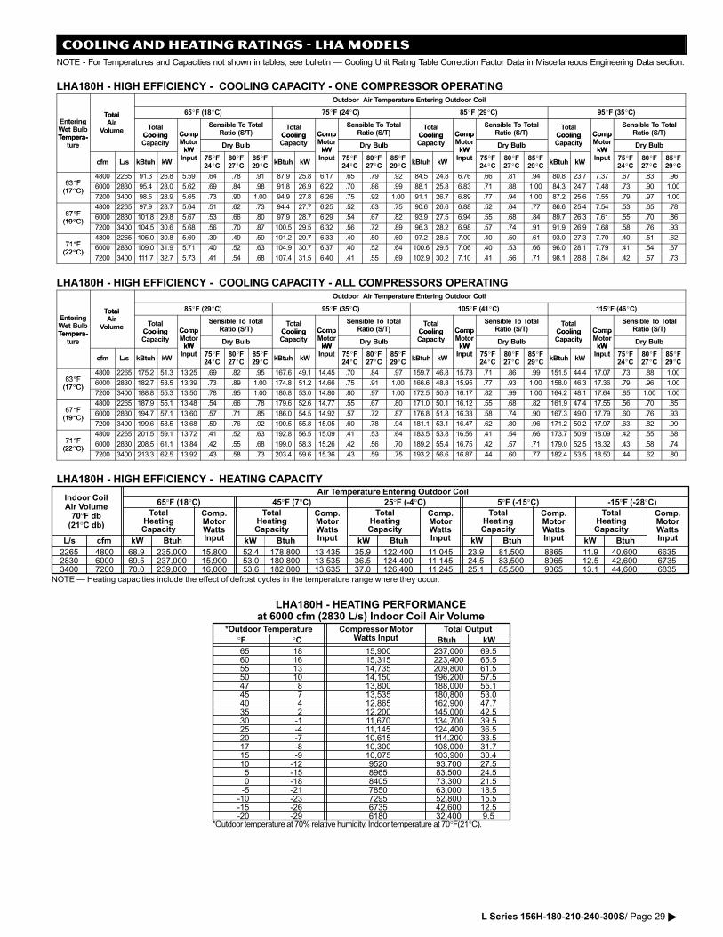
COOLING AND HEATING RATINGS − LHA MODELS
NOTE − For Temperatures and Capacities not shown in tables, see bulletin � Cooling Unit Rating Table Correction Factor Data in Miscellaneous Engineering Data section.
LHA180H − HIGH EFFICIENCY − COOLING CAPACITY − ONE COMPRESSOR OPERATINGOutdoor Air Temperature Entering Outdoor Coil
Total 65�F (18�C) 75�F (24�C) 85�F (29�C) 95�F (35�C)
EnteringWet BulbTempera�
TotalAir
Volume TotalCooling Comp
Sensible To TotalRatio (S/T)
TotalCooling Comp
Sensible To TotalRatio (S/T)
TotalCooling Comp
Sensible To TotalRatio (S/T)
TotalCooling Comp
Sensible To TotalRatio (S/T)
Tempera�ture
CoolingCapacity
CompMotorkW
Dry Bulb
CoolingCapacity
CompMotorkW
Dry Bulb
CoolingCapacity
CompMotorkW
Dry Bulb
CoolingCapacity
CompMotorkW
Dry Bulbture
cfm L/s kBtuh kW
kWInput 75�F
24�C80�F27�C
85�F29�C
kBtuh kW
kWInput 75�F
24�C80�F27�C
85�F29�C
kBtuh kW
kWInput 75�F
24�C80�F27�C
85�F29�C
kBtuh kW
kWInput 75�F
24�C80�F27�C
85�F29�C
63�F4800 2265 91.3 26.8 5.59 .64 .78 .91 87.9 25.8 6.17 .65 .79 .92 84.5 24.8 6.76 .66 .81 .94 80.8 23.7 7.37 .67 .83 .96
63�F(17�C)
6000 2830 95.4 28.0 5.62 .69 .84 .98 91.8 26.9 6.22 .70 .86 .99 88.1 25.8 6.83 .71 .88 1.00 84.3 24.7 7.48 .73 .90 1.00(17�C)
7200 3400 98.5 28.9 5.65 .73 .90 1.00 94.9 27.8 6.26 .75 .92 1.00 91.1 26.7 6.89 .77 .94 1.00 87.2 25.6 7.55 .79 .97 1.00
67�F4800 2265 97.9 28.7 5.64 .51 .62 .73 94.4 27.7 6.25 .52 .63 .75 90.6 26.6 6.88 .52 .64 .77 86.6 25.4 7.54 .53 .65 .78
67�F(19�C)
6000 2830 101.8 29.8 5.67 .53 .66 .80 97.9 28.7 6.29 .54 .67 .82 93.9 27.5 6.94 .55 .68 .84 89.7 26.3 7.61 .55 .70 .86(19�C)
7200 3400 104.5 30.6 5.68 .56 .70 .87 100.5 29.5 6.32 .56 .72 .89 96.3 28.2 6.98 .57 .74 .91 91.9 26.9 7.68 .58 .76 .93
71�F4800 2265 105.0 30.8 5.69 .39 .49 .59 101.2 29.7 6.33 .40 .50 .60 97.2 28.5 7.00 .40 .50 .61 93.0 27.3 7.70 .40 .51 .62
71�F(22�C)
6000 2830 109.0 31.9 5.71 .40 .52 .63 104.9 30.7 6.37 .40 .52 .64 100.6 29.5 7.06 .40 .53 .66 96.0 28.1 7.79 .41 .54 .67(22�C)
7200 3400 111.7 32.7 5.73 .41 .54 .68 107.4 31.5 6.40 .41 .55 .69 102.9 30.2 7.10 .41 .56 .71 98.1 28.8 7.84 .42 .57 .73
LHA180H − HIGH EFFICIENCY − COOLING CAPACITY − ALL COMPRESSORS OPERATINGOutdoor Air Temperature Entering Outdoor Coil
Total 85�F (29�C) 95�F (35�C) 105�F (41�C) 115�F (46�C)
EnteringWet BulbTempera�
TotalAir
Volume TotalCooling Comp
Sensible To TotalRatio (S/T)
TotalCooling Comp
Sensible To TotalRatio (S/T)
TotalCooling Comp
Sensible To TotalRatio (S/T)
TotalCooling Comp
Sensible To TotalRatio (S/T)
Tempera�ture
CoolingCapacity
CompMotorkW
Dry Bulb
CoolingCapacity
CompMotorkW
Dry Bulb
CoolingCapacity
CompMotorkW
Dry Bulb
CoolingCapacity
CompMotorkW
Dry Bulbture
cfm L/s kBtuh kW
kWInput 75�F
24�C80�F27�C
85�F29�C
kBtuh kW
kWInput 75�F
24�C80�F27�C
85�F29�C
kBtuh kW
kWInput 75�F
24�C80�F27�C
85�F29�C
kBtuh kW
kWInput 75�F
24�C80�F27�C
85�F29�C
63�F4800 2265 175.2 51.3 13.25 .69 .82 .95 167.6 49.1 14.45 .70 .84 .97 159.7 46.8 15.73 .71 .86 .99 151.5 44.4 17.07 .73 .88 1.00
63�F(17�C)
6000 2830 182.7 53.5 13.39 .73 .89 1.00 174.8 51.2 14.66 .75 .91 1.00 166.6 48.8 15.95 .77 .93 1.00 158.0 46.3 17.36 .79 .96 1.00(17�C)
7200 3400 188.8 55.3 13.50 .78 .95 1.00 180.8 53.0 14.80 .80 .97 1.00 172.5 50.6 16.17 .82 .99 1.00 164.2 48.1 17.64 .85 1.00 1.00
67�F4800 2265 187.9 55.1 13.48 .54 .66 .78 179.6 52.6 14.77 .55 .67 .80 171.0 50.1 16.12 .55 .68 .82 161.9 47.4 17.55 .56 .70 .85
67�F(19�C)
6000 2830 194.7 57.1 13.60 .57 .71 .85 186.0 54.5 14.92 .57 .72 .87 176.8 51.8 16.33 .58 .74 .90 167.3 49.0 17.79 .60 .76 .93(19�C)
7200 3400 199.6 58.5 13.68 .59 .76 .92 190.5 55.8 15.05 .60 .78 .94 181.1 53.1 16.47 .62 .80 .96 171.2 50.2 17.97 .63 .82 .99
71�F4800 2265 201.5 59.1 13.72 .41 .52 .63 192.8 56.5 15.09 .41 .53 .64 183.5 53.8 16.56 .41 .54 .66 173.7 50.9 18.09 .42 .55 .68
71�F(22�C)
6000 2830 208.5 61.1 13.84 .42 .55 .68 199.0 58.3 15.26 .42 .56 .70 189.2 55.4 16.75 .42 .57 .71 179.0 52.5 18.32 .43 .58 .74(22�C)
7200 3400 213.3 62.5 13.92 .43 .58 .73 203.4 59.6 15.36 .43 .59 .75 193.2 56.6 16.87 .44 .60 .77 182.4 53.5 18.50 .44 .62 .80
LHA180H − HIGH EFFICIENCY − HEATING CAPACITY
2265 4800 68.9 235,000 15,800 52.4 178,800 13,435 35.9 122,400 11,045 23.9 81,500 8865 11.9 40,600 66352830 6000 69.5 237,000 15,900 53.0 180,800 13,535 36.5 124,400 11,145 24.5 83,500 8965 12.5 42,600 67353400 7200 70.0 239,000 16,000 53.6 182,800 13,635 37.0 126,400 11,245 25.1 85,500 9065 13.1 44,600 6835
NOTE � Heating capacities include the effect of defrost cycles in the temperature range where they occur.
Indoor CoilAir Volume70°F db(21°C db)
TotalHeatingCapacity
Comp.MotorWattsInputL/s cfm kW Btuh kW Btuh kW Btuh kW Btuh kW Btuh
TotalHeatingCapacity
Comp.MotorWattsInput
TotalHeatingCapacity
Comp.MotorWattsInput
TotalHeatingCapacity
Comp.MotorWattsInput
TotalHeatingCapacity
Comp.MotorWattsInput
Air Temperature Entering Outdoor Coil
65°F (18°C) 45°F (7°C) 25°F (�4°C) 5°F (�15°C) �15°F (�28°C)
LHA180H − HEATING PERFORMANCEat 6000 cfm (2830 L/s) Indoor Coil Air Volume
*Outdoor Temperature
°F °CCompressor Motor
Watts InputTotal Output
kWBtuh
65 1860 1655 1350 1047 845 740 435 230 �125 �420 �717 �815 �910 �125 �150 �18�5 �21
�10 �23�15 �26�20 �29
15,900 237,000 69.515,315 223,400 65.514,735 209,800 61.514,150 196,200 57.513,800 188,000 55.113,535 180,800 53.012,865 162,900 47.712,200 145,000 42.511,670 134,700 39.511,145 124,400 36.510,615 114,200 33.510,300 108,000 31.710,075 103,900 30.49520 93,700 27.58965 83,500 24.58405 73,300 21.57850 63,000 18.57295 52,800 15.56735 42,600 12.56180 32,400 9.5
*Outdoor�temperature�at�70%�relative�humidity.�Indoor�temperature�at�70°F�(21°C).
L Series 156H−180−210−240−300S/ Page 29 �
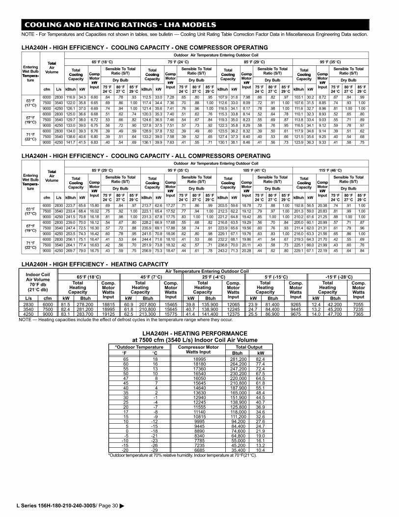
COOLING AND HEATING RATINGS − LHA MODELS
NOTE − For Temperatures and Capacities not shown in tables, see bulletin � Cooling Unit Rating Table Correction Factor Data in Miscellaneous Engineering Data section.
LHA240H − HIGH EFFICIENCY − COOLING CAPACITY − ONE COMPRESSOR OPERATINGOutdoor Air Temperature Entering Outdoor Coil
Total 65�F (18�C) 75�F (24�C) 85�F (29�C) 95�F (35�C)
EnteringWet BulbTempera�
TotalAir
Volume TotalCooling Comp
Sensible To TotalRatio (S/T)
TotalCooling Comp
Sensible To TotalRatio (S/T)
TotalCooling Comp
Sensible To TotalRatio (S/T)
TotalCooling Comp
Sensible To TotalRatio (S/T)
Tempera�ture
CoolingCapacity
CompMotorkW
Dry Bulb
CoolingCapacity
CompMotorkW
Dry Bulb
CoolingCapacity
CompMotorkW
Dry Bulb
CoolingCapacity
CompMotorkW
Dry Bulbture
cfm L/s kBtuh kW
kWInput 75�F
24�C80�F27�C
85�F29�C
kBtuh kW
kWInput 75�F
24�C80�F27�C
85�F29�C
kBtuh kW
kWInput 75�F
24�C80�F27�C
85�F29�C
kBtuh kW
kWInput 75�F
24�C80�F27�C
85�F29�C
63�F6000 2830 116.9 34.3 6.60 .64 .78 .93 112.5 33.0 7.28 .65 .80 .95 107.9 31.6 7.98 .66 .82 .97 103.1 30.2 8.72 .67 .84 .99
63�F(17�C)
7500 3540 122.0 35.8 6.65 .69 .86 1.00 117.4 34.4 7.36 .70 .88 1.00 112.6 33.0 8.09 .72 .91 1.00 107.6 31.5 8.85 .74 .93 1.00(17�C)
9000 4250 126.1 37.0 6.69 .74 .94 1.00 121.4 35.6 7.41 .76 .96 1.00 116.5 34.1 8.17 .78 .98 1.00 111.6 32.7 8.96 .81 1.00 1.00
67�F6000 2830 125.0 36.6 6.68 .51 .62 .74 120.3 35.3 7.40 .51 .62 .76 115.3 33.8 8.14 .52 .64 .78 110.1 32.3 8.93 .52 .65 .80
67�F(19�C)
7500 3540 129.7 38.0 6.72 .53 .66 .82 124.6 36.5 7.46 .54 .67 .84 119.3 35.0 8.23 .55 .69 .87 113.8 33.4 9.03 .55 .71 .89(19�C)
9000 4250 133.0 39.0 6.75 .56 .72 .90 127.8 37.5 7.51 .57 .73 .92 122.3 35.8 8.29 .58 .76 .95 116.5 34.1 9.12 .59 .78 .97
71�F6000 2830 134.0 39.3 6.76 .39 .49 .59 128.9 37.8 7.52 .39 .49 .60 123.5 36.2 8.32 .39 .50 .61 117.9 34.6 9.14 .39 .51 .62
71�F(22�C)
7500 3540 138.6 40.6 6.80 .39 .51 .64 133.2 39.0 7.58 .39 .52 .65 127.4 37.3 8.40 .40 .53 .66 121.5 35.6 9.25 .40 .54 .68(22�C)
9000 4250 141.7 41.5 6.83 .40 .54 .69 136.1 39.9 7.63 .41 .55 .71 130.1 38.1 8.46 .41 .56 .73 123.9 36.3 9.33 .41 .58 .75
LHA240H − HIGH EFFICIENCY − COOLING CAPACITY − ALL COMPRESSORS OPERATINGOutdoor Air Temperature Entering Outdoor Coil
Total 85�F (29�C) 95�F (35�C) 105�F (41�C) 115�F (46�C)
EnteringWet BulbTempera�
TotalAir
Volume TotalCooling Comp
Sensible To TotalRatio (S/T)
TotalCooling Comp
Sensible To TotalRatio (S/T)
TotalCooling Comp
Sensible To TotalRatio (S/T)
TotalCooling Comp
Sensible To TotalRatio (S/T)
Tempera�ture
CoolingCapacity
CompMotorkW
Dry Bulb
CoolingCapacity
CompMotorkW
Dry Bulb
CoolingCapacity
CompMotorkW
Dry Bulb
CoolingCapacity
CompMotorkW
Dry Bulbture
cfm L/s kBtuh kW
kWInput 75�F
24�C80�F27�C
85�F29�C
kBtuh kW
kWInput 75�F
24�C80�F27�C
85�F29�C
kBtuh kW
kWInput 75�F
24�C80�F27�C
85�F29�C
kBtuh kW
kWInput 75�F
24�C80�F27�C
85�F29�C
63�F6000 2830 223.7 65.6 15.80 .69 .84 .97 213.7 62.6 17.27 .71 .86 .99 203.5 59.6 18.78 .72 .88 1.00 192.8 56.5 20.38 .74 .91 1.00
63�F(17�C)
7500 3540 233.4 68.4 16.02 .75 .92 1.00 223.1 65.4 17.52 .77 .94 1.00 212.3 62.2 19.12 .79 .97 1.00 201.3 59.0 20.83 .81 .99 1.00(17�C)
9000 4250 241.5 70.8 16.18 .81 .98 1.00 231.3 67.8 17.75 .83 1.00 1.00 221.2 64.8 19.42 .85 1.00 1.00 210.2 61.6 21.25 .88 1.00 1.00
67�F6000 2830 239.0 70.0 16.12 .54 .67 .80 228.2 66.9 17.68 .55 .68 .82 216.8 63.5 19.29 .56 .70 .84 205.0 60.1 20.99 .57 .71 .87
67�F(19�C)
7500 3540 247.4 72.5 16.30 .57 .72 .88 235.9 69.1 17.88 .58 .74 .91 223.9 65.6 19.56 .60 .76 .93 211.4 62.0 21.31 .61 .79 .96(19�C)
9000 4250 253.5 74.3 16.42 .60 .78 .95 241.5 70.8 18.06 .62 .80 .98 229.1 67.1 19.76 .63 .83 1.00 216.0 63.3 21.56 .65 .86 1.00
71�F6000 2830 256.1 75.1 16.47 .41 .53 .64 244.4 71.6 18.10 .41 .53 .66 232.2 68.1 19.86 .41 .54 .67 219.3 64.3 21.70 .42 .55 .69
71�F(22�C)
7500 3540 264.1 77.4 16.63 .42 .56 .70 251.9 73.8 18.32 .42 .57 .71 238.8 70.0 20.11 .43 .58 .73 225.1 66.0 21.99 .43 .60 .76(22�C)
9000 4250 269.7 79.0 16.75 .43 .59 .75 256.9 75.3 18.47 .44 .61 .78 243.2 71.3 20.28 .44 .62 .80 229.1 67.1 22.19 .45 .64 .84
LHA240H − HIGH EFFICIENCY − HEATING CAPACITY
2830 6000 81.5 278,200 18815 60.9 207,800 15465 39.8 135,900 12065 23.9 81,400 9265 12.4 42,200 70553540 7500 82.4 281,200 18995 61.8 210,800 15645 40.7 138,900 12245 24.7 84,400 9445 13.2 45,200 72354250 9000 83.1 283,700 19125 62.5 213,300 15775 41.4 141,400 12375 25.5 86,900 9675 14.0 47,700 7365
NOTE � Heating capacities include the effect of defrost cycles in the temperature range where they occur.
Indoor CoilAir Volume70°F db(21°C db)
TotalHeatingCapacity
Comp.MotorWattsInputL/s cfm kW Btuh kW Btuh kW Btuh kW Btuh kW Btuh
TotalHeatingCapacity
Comp.MotorWattsInput
TotalHeatingCapacity
Comp.MotorWattsInput
TotalHeatingCapacity
Comp.MotorWattsInput
TotalHeatingCapacity
Comp.MotorWattsInput
Air Temperature Entering Outdoor Coil
65°F (18°C) 45°F (7°C) 25°F (�4°C) 5°F (�15°C) �15°F (�28°C)
LHA240H − HEATING PERFORMANCEat 7500 cfm (3540 L/s) Indoor Coil Air Volume
*Outdoor Temperature
°F °CCompressor Motor
Watts InputTotal Output
kWBtuh
65 1860 1655 1350 1047 845 740 435 230 �125 �420 �717 �815 �910 �125 �150 �18�5 �21
�10 �23�15 �26�20 �29
18995 281,200 82.418180 264,200 77.417360 247,200 72.416540 230,200 67.516050 220,000 64.515645 210,800 61.814640 187,900 55.113630 165,000 48.412940 151,900 44.512245 138,900 40.711555 125,800 36.911140 118,000 34.610815 111,200 32.69995 94,200 27.69445 84,400 24.78890 74,600 21.98340 64,800 19.07785 55,000 16.17235 45,200 13.26685 35,400 10.4
*Outdoor�temperature�at�70%�relative�humidity.�Indoor�temperature�at�70°F�(21°C).
L Series 156H−180−210−240−300S/ Page 30 �
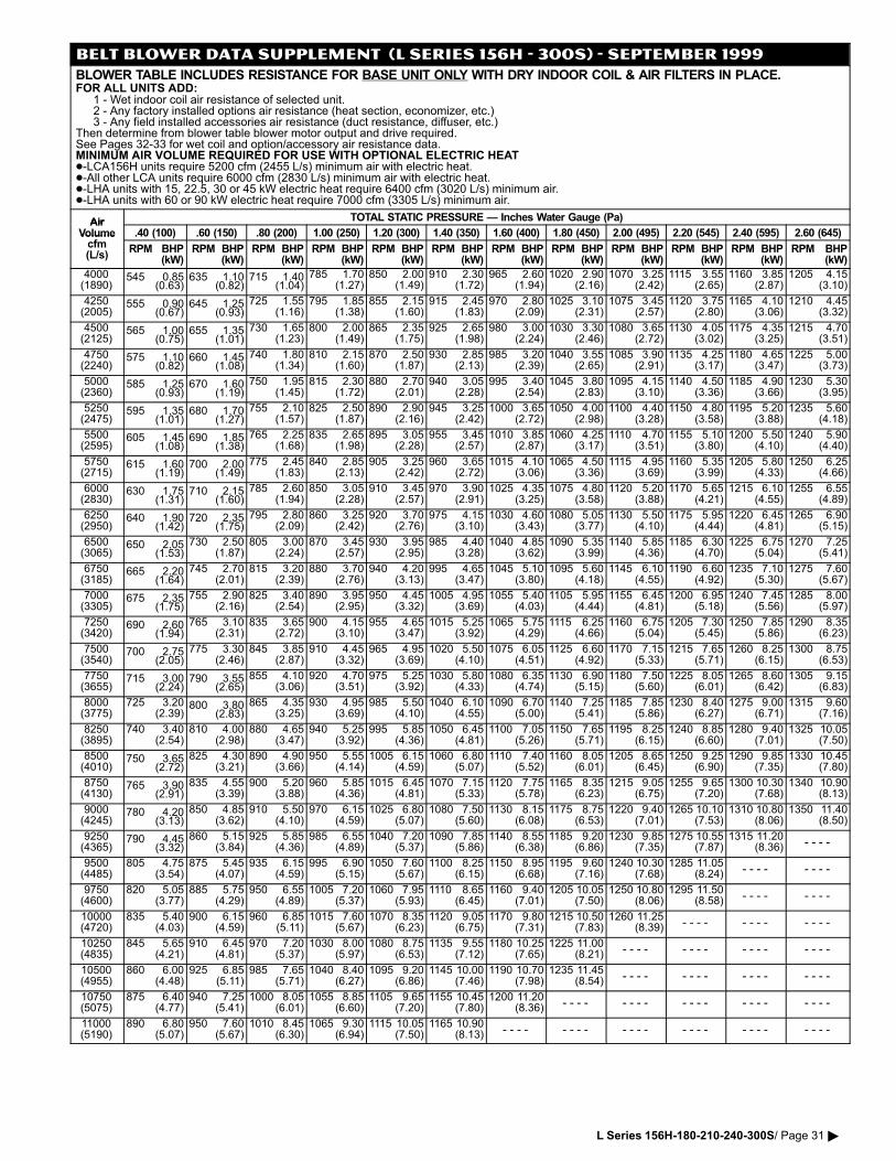
BELT BLOWER DATA SUPPLEMENT (L SERIES 156H − 300S) − SEPTEMBER 1999
BLOWER TABLE INCLUDES RESISTANCE FOR BASE UNIT ONLY WITH DRY INDOOR COIL & AIR FILTERS IN PLACE.FOR ALL UNITS ADD:
1 − Wet indoor coil air resistance of selected unit.2 − Any factory installed options air resistance (heat section, economizer, etc.)3 − Any field installed accessories air resistance (duct resistance, diffuser, etc.)
Then determine from blower table blower motor output and drive required.See Pages 32−33 for wet coil and option/accessory air resistance data.MINIMUM AIR VOLUME REQUIRED FOR USE WITH OPTIONAL ELECTRIC HEAT −LCA156H units require 5200 cfm (2455 L/s) minimum air with electric heat. −All other LCA units require 6000 cfm (2830 L/s) minimum air with electric heat. −LHA units with 15, 22.5, 30 or 45 kW electric heat require 6400 cfm (3020 L/s) minimum air. −LHA units with 60 or 90 kW electric heat require 7000 cfm (3305 L/s) minimum air.
Air TOTAL STATIC PRESSURE � Inches Water Gauge (Pa)AirVolume
f.40 (100) .60 (150) .80 (200) 1.00 (250) 1.20 (300) 1.40 (350) 1.60 (400) 1.80 (450) 2.00 (495) 2.20 (545) 2.40 (595) 2.60 (645)Volume
cfm(L/s)
RPM BHP(kW)
RPM BHP(kW)
RPM BHP(kW)
RPM BHP(kW)
RPM BHP(kW)
RPM BHP(kW)
RPM BHP(kW)
RPM BHP(kW)
RPM BHP(kW)
RPM BHP(kW)
RPM BHP(kW)
RPM BHP(kW)
4000(1890)
545 0.85(0.63)
635 1.10(0.82)
715 1.40(1.04)
785 1.70(1.27)
850 2.00(1.49)
910 2.30(1.72)
965 2.60(1.94)
1020 2.90(2.16)
1070 3.25(2.42)
1115 3.55(2.65)
1160 3.85(2.87)
1205 4.15(3.10)
4250(2005)
555 0.90(0.67)
645 1.25(0.93)
725 1.55(1.16)
795 1.85(1.38)
855 2.15(1.60)
915 2.45(1.83)
970 2.80(2.09)
1025 3.10(2.31)
1075 3.45(2.57)
1120 3.75(2.80)
1165 4.10(3.06)
1210 4.45(3.32)
4500(2125)
565 1.00(0.75)
655 1.35(1.01)
730 1.65(1.23)
800 2.00(1.49)
865 2.35(1.75)
925 2.65(1.98)
980 3.00(2.24)
1030 3.30(2.46)
1080 3.65(2.72)
1130 4.05(3.02)
1175 4.35(3.25)
1215 4.70(3.51)
4750(2240)
575 1.10(0.82)
660 1.45(1.08)
740 1.80(1.34)
810 2.15(1.60)
870 2.50(1.87)
930 2.85(2.13)
985 3.20(2.39)
1040 3.55(2.65)
1085 3.90(2.91)
1135 4.25(3.17)
1180 4.65(3.47)
1225 5.00(3.73)
5000(2360)
585 1.25(0.93)
670 1.60(1.19)
750 1.95(1.45)
815 2.30(1.72)
880 2.70(2.01)
940 3.05(2.28)
995 3.40(2.54)
1045 3.80(2.83)
1095 4.15(3.10)
1140 4.50(3.36)
1185 4.90(3.66)
1230 5.30(3.95)
5250(2475)
595 1.35(1.01)
680 1.70(1.27)
755 2.10(1.57)
825 2.50(1.87)
890 2.90(2.16)
945 3.25(2.42)
1000 3.65(2.72)
1050 4.00(2.98)
1100 4.40(3.28)
1150 4.80(3.58)
1195 5.20(3.88)
1235 5.60(4.18)
5500(2595)
605 1.45(1.08)
690 1.85(1.38)
765 2.25(1.68)
835 2.65(1.98)
895 3.05(2.28)
955 3.45(2.57)
1010 3.85(2.87)
1060 4.25(3.17)
1110 4.70(3.51)
1155 5.10(3.80)
1200 5.50(4.10)
1240 5.90(4.40)
5750(2715)
615 1.60(1.19)
700 2.00(1.49)
775 2.45(1.83)
840 2.85(2.13)
905 3.25(2.42)
960 3.65(2.72)
1015 4.10(3.06)
1065 4.50(3.36)
1115 4.95(3.69)
1160 5.35(3.99)
1205 5.80(4.33)
1250 6.25(4.66)
6000(2830)
630 1.75(1.31)
710 2.15(1.60)
785 2.60(1.94)
850 3.05(2.28)
910 3.45(2.57)
970 3.90(2.91)
1025 4.35(3.25)
1075 4.80(3.58)
1120 5.20(3.88)
1170 5.65(4.21)
1215 6.10(4.55)
1255 6.55(4.89)
6250(2950)
640 1.90(1.42)
720 2.35(1.75)
795 2.80(2.09)
860 3.25(2.42)
920 3.70(2.76)
975 4.15(3.10)
1030 4.60(3.43)
1080 5.05(3.77)
1130 5.50(4.10)
1175 5.95(4.44)
1220 6.45(4.81)
1265 6.90(5.15)
6500(3065)
650 2.05(1.53)
730 2.50(1.87)
805 3.00(2.24)
870 3.45(2.57)
930 3.95(2.95)
985 4.40(3.28)
1040 4.85(3.62)
1090 5.35(3.99)
1140 5.85(4.36)
1185 6.30(4.70)
1225 6.75(5.04)
1270 7.25(5.41)
6750(3185)
665 2.20(1.64)
745 2.70(2.01)
815 3.20(2.39)
880 3.70(2.76)
940 4.20(3.13)
995 4.65(3.47)
1045 5.10(3.80)
1095 5.60(4.18)
1145 6.10(4.55)
1190 6.60(4.92)
1235 7.10(5.30)
1275 7.60(5.67)
7000(3305)
675 2.35(1.75)
755 2.90(2.16)
825 3.40(2.54)
890 3.95(2.95)
950 4.45(3.32)
1005 4.95(3.69)
1055 5.40(4.03)
1105 5.95(4.44)
1155 6.45(4.81)
1200 6.95(5.18)
1240 7.45(5.56)
1285 8.00(5.97)
7250(3420)
690 2.60(1.94)
765 3.10(2.31)
835 3.65(2.72)
900 4.15(3.10)
955 4.65(3.47)
1015 5.25(3.92)
1065 5.75(4.29)
1115 6.25(4.66)
1160 6.75(5.04)
1205 7.30(5.45)
1250 7.85(5.86)
1290 8.35(6.23)
7500(3540)
700 2.75(2.05)
775 3.30(2.46)
845 3.85(2.87)
910 4.45(3.32)
965 4.95(3.69)
1020 5.50(4.10)
1075 6.05(4.51)
1125 6.60(4.92)
1170 7.15(5.33)
1215 7.65(5.71)
1260 8.25(6.15)
1300 8.75(6.53)
7750(3655)
715 3.00(2.24)
790 3.55(2.65)
855 4.10(3.06)
920 4.70(3.51)
975 5.25(3.92)
1030 5.80(4.33)
1080 6.35(4.74)
1130 6.90(5.15)
1180 7.50(5.60)
1225 8.05(6.01)
1265 8.60(6.42)
1305 9.15(6.83)
8000(3775)
725 3.20(2.39)
800 3.80(2.83)
865 4.35(3.25)
930 4.95(3.69)
985 5.50(4.10)
1040 6.10(4.55)
1090 6.70(5.00)
1140 7.25(5.41)
1185 7.85(5.86)
1230 8.40(6.27)
1275 9.00(6.71)
1315 9.60(7.16)
8250(3895)
740 3.40(2.54)
810 4.00(2.98)
880 4.65(3.47)
940 5.25(3.92)
995 5.85(4.36)
1050 6.45(4.81)
1100 7.05(5.26)
1150 7.65(5.71)
1195 8.25(6.15)
1240 8.85(6.60)
1280 9.40(7.01)
1325 10.05(7.50)
8500(4010)
750 3.65(2.72)
825 4.30(3.21)
890 4.90(3.66)
950 5.55(4.14)
1005 6.15(4.59)
1060 6.80(5.07)
1110 7.40(5.52)
1160 8.05(6.01)
1205 8.65(6.45)
1250 9.25(6.90)
1290 9.85(7.35)
1330 10.45(7.80)
8750(4130)
765 3.90(2.91)
835 4.55(3.39)
900 5.20(3.88)
960 5.85(4.36)
1015 6.45(4.81)
1070 7.15(5.33)
1120 7.75(5.78)
1165 8.35(6.23)
1215 9.05(6.75)
1255 9.65(7.20)
1300 10.30(7.68)
1340 10.90(8.13)
9000(4245)
780 4.20(3.13)
850 4.85(3.62)
910 5.50(4.10)
970 6.15(4.59)
1025 6.80(5.07)
1080 7.50(5.60)
1130 8.15(6.08)
1175 8.75(6.53)
1220 9.40(7.01)
1265 10.10(7.53)
1310 10.80(8.06)
1350 11.40(8.50)
9250(4365)
790 4.45(3.32)
860 5.15(3.84)
925 5.85(4.36)
985 6.55(4.89)
1040 7.20(5.37)
1090 7.85(5.86)
1140 8.55(6.38)
1185 9.20(6.86)
1230 9.85(7.35)
1275 10.55(7.87)
1315 11.20(8.36) − − − −
9500(4485)
805 4.75(3.54)
875 5.45(4.07)
935 6.15(4.59)
995 6.90(5.15)
1050 7.60(5.67)
1100 8.25(6.15)
1150 8.95(6.68)
1195 9.60(7.16)
1240 10.30(7.68)
1285 11.05(8.24) − − − − − − − −
9750(4600)
820 5.05(3.77)
885 5.75(4.29)
950 6.55(4.89)
1005 7.20(5.37)
1060 7.95(5.93)
1110 8.65(6.45)
1160 9.40(7.01)
1205 10.05(7.50)
1250 10.80(8.06)
1295 11.50(8.58) − − − − − − − −
10000(4720)
835 5.40(4.03)
900 6.15(4.59)
960 6.85(5.11)
1015 7.60(5.67)
1070 8.35(6.23)
1120 9.05(6.75)
1170 9.80(7.31)
1215 10.50(7.83)
1260 11.25(8.39) − − − − − − − − − − − −
10250(4835)
845 5.65(4.21)
910 6.45(4.81)
970 7.20(5.37)
1030 8.00(5.97)
1080 8.75(6.53)
1135 9.55(7.12)
1180 10.25(7.65)
1225 11.00(8.21) − − − − − − − − − − − − − − − −
10500(4955)
860 6.00(4.48)
925 6.85(5.11)
985 7.65(5.71)
1040 8.40(6.27)
1095 9.20(6.86)
1145 10.00(7.46)
1190 10.70(7.98)
1235 11.45(8.54) − − − − − − − − − − − − − − − −
10750(5075)
875 6.40(4.77)
940 7.25(5.41)
1000 8.05(6.01)
1055 8.85(6.60)
1105 9.65(7.20)
1155 10.45(7.80)
1200 11.20(8.36) − − − − − − − − − − − − − − − − − − − −
11000(5190)
890 6.80(5.07)
950 7.60(5.67)
1010 8.45(6.30)
1065 9.30(6.94)
1115 10.05(7.50)
1165 10.90(8.13) − − − − − − − − − − − − − − − − − − − − − − − −
L Series 156H−180−210−240−300S/ Page 31 �
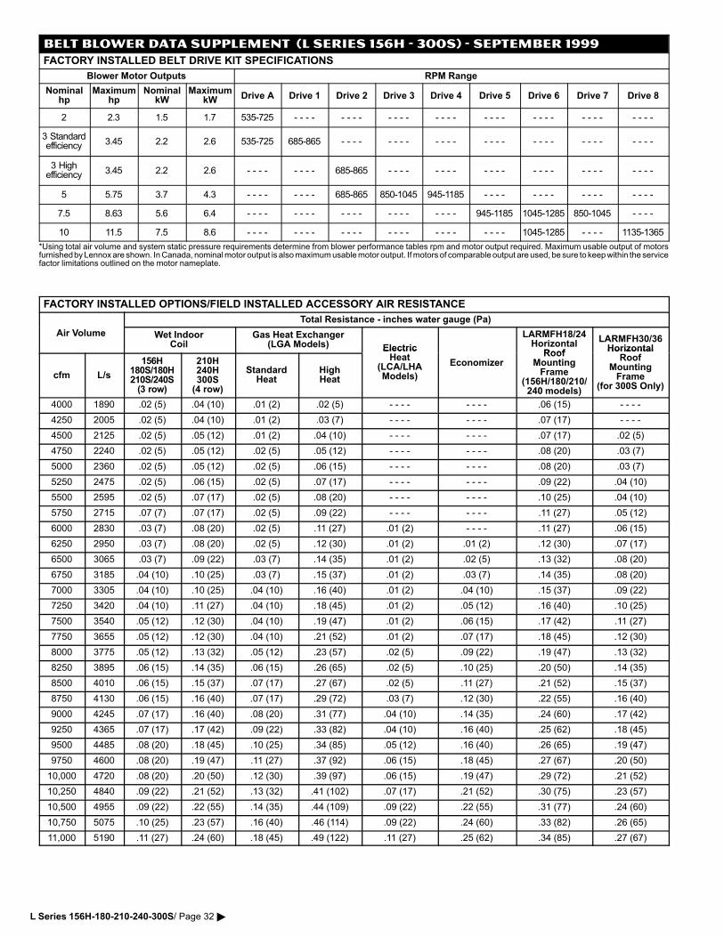
BELT BLOWER DATA SUPPLEMENT (L SERIES 156H − 300S) − SEPTEMBER 1999
FACTORY INSTALLED BELT DRIVE KIT SPECIFICATIONS
Blower Motor Outputs RPM Range
Nominalhp
Maximumhp
NominalkW
MaximumkW Drive A Drive 1 Drive 2 Drive 3 Drive 4 Drive 5 Drive 6 Drive 7 Drive 8
2 2.3 1.5 1.7 535−725 − − − − − − − − − − − − − − − − − − − − − − − − − − − − − − − −
3 Standardefficiency 3.45 2.2 2.6 535−725 685−865 − − − − − − − − − − − − − − − − − − − − − − − − − − − −
3 Highefficiency 3.45 2.2 2.6 − − − − − − − − 685−865 − − − − − − − − − − − − − − − − − − − − − − − −
5 5.75 3.7 4.3 − − − − − − − − 685−865 850−1045 945−1185 − − − − − − − − − − − − − − − −
7.5 8.63 5.6 6.4 − − − − − − − − − − − − − − − − − − − − 945−1185 1045−1285 850−1045 − − − −
10 11.5 7.5 8.6 − − − − − − − − − − − − − − − − − − − − − − − − 1045−1285 − − − − 1135−1365
*Using total air volume and system static pressure requirements determine from blower performance tables rpm and motor output required. Maximum usable output of motorsfurnished by Lennox are shown. In Canada, nominal motor output is also maximum usable motor output. If motors of comparable output are used, be sure to keep within the servicefactor limitations outlined on the motor nameplate.
FACTORY INSTALLED OPTIONS/FIELD INSTALLED ACCESSORY AIR RESISTANCE
Total Resistance − inches water gauge (Pa)
Air Volume Wet IndoorCoil
Gas Heat Exchanger(LGA Models) Electric
LARMFH18/24Horizontal
Roof
LARMFH30/36Horizontal
cfm L/s
156H180S/180H210S/240S(3 row)
210H240H300S(4 row)
StandardHeat
HighHeat
ElectricHeat
(LCA/LHAModels)
EconomizerRoof
MountingFrame
(156H/180/210/240 models)
HorizontalRoof
MountingFrame
(for 300S Only)
4000 1890 .02 (5) .04 (10) .01 (2) .02 (5) − − − − − − − − .06 (15) − − − −
4250 2005 .02 (5) .04 (10) .01 (2) .03 (7) − − − − − − − − .07 (17) − − − −
4500 2125 .02 (5) .05 (12) .01 (2) .04 (10) − − − − − − − − .07 (17) .02 (5)
4750 2240 .02 (5) .05 (12) .02 (5) .05 (12) − − − − − − − − .08 (20) .03 (7)
5000 2360 .02 (5) .05 (12) .02 (5) .06 (15) − − − − − − − − .08 (20) .03 (7)
5250 2475 .02 (5) .06 (15) .02 (5) .07 (17) − − − − − − − − .09 (22) .04 (10)
5500 2595 .02 (5) .07 (17) .02 (5) .08 (20) − − − − − − − − .10 (25) .04 (10)
5750 2715 .07 (7) .07 (17) .02 (5) .09 (22) − − − − − − − − .11 (27) .05 (12)
6000 2830 .03 (7) .08 (20) .02 (5) .11 (27) .01 (2) − − − − .11 (27) .06 (15)
6250 2950 .03 (7) .08 (20) .02 (5) .12 (30) .01 (2) .01 (2) .12 (30) .07 (17)
6500 3065 .03 (7) .09 (22) .03 (7) .14 (35) .01 (2) .02 (5) .13 (32) .08 (20)
6750 3185 .04 (10) .10 (25) .03 (7) .15 (37) .01 (2) .03 (7) .14 (35) .08 (20)
7000 3305 .04 (10) .10 (25) .04 (10) .16 (40) .01 (2) .04 (10) .15 (37) .09 (22)
7250 3420 .04 (10) .11 (27) .04 (10) .18 (45) .01 (2) .05 (12) .16 (40) .10 (25)
7500 3540 .05 (12) .12 (30) .04 (10) .19 (47) .01 (2) .06 (15) .17 (42) .11 (27)
7750 3655 .05 (12) .12 (30) .04 (10) .21 (52) .01 (2) .07 (17) .18 (45) .12 (30)
8000 3775 .05 (12) .13 (32) .05 (12) .23 (57) .02 (5) .09 (22) .19 (47) .13 (32)
8250 3895 .06 (15) .14 (35) .06 (15) .26 (65) .02 (5) .10 (25) .20 (50) .14 (35)
8500 4010 .06 (15) .15 (37) .07 (17) .27 (67) .02 (5) .11 (27) .21 (52) .15 (37)
8750 4130 .06 (15) .16 (40) .07 (17) .29 (72) .03 (7) .12 (30) .22 (55) .16 (40)
9000 4245 .07 (17) .16 (40) .08 (20) .31 (77) .04 (10) .14 (35) .24 (60) .17 (42)
9250 4365 .07 (17) .17 (42) .09 (22) .33 (82) .04 (10) .16 (40) .25 (62) .18 (45)
9500 4485 .08 (20) .18 (45) .10 (25) .34 (85) .05 (12) .16 (40) .26 (65) .19 (47)
9750 4600 .08 (20) .19 (47) .11 (27) .37 (92) .06 (15) .18 (45) .27 (67) .20 (50)
10,000 4720 .08 (20) .20 (50) .12 (30) .39 (97) .06 (15) .19 (47) .29 (72) .21 (52)
10,250 4840 .09 (22) .21 (52) .13 (32) .41 (102) .07 (17) .21 (52) .30 (75) .23 (57)
10,500 4955 .09 (22) .22 (55) .14 (35) .44 (109) .09 (22) .22 (55) .31 (77) .24 (60)
10,750 5075 .10 (25) .23 (57) .16 (40) .46 (114) .09 (22) .24 (60) .33 (82) .26 (65)
11,000 5190 .11 (27) .24 (60) .18 (45) .49 (122) .11 (27) .25 (62) .34 (85) .27 (67)
L Series 156H−180−210−240−300S/ Page 32 �
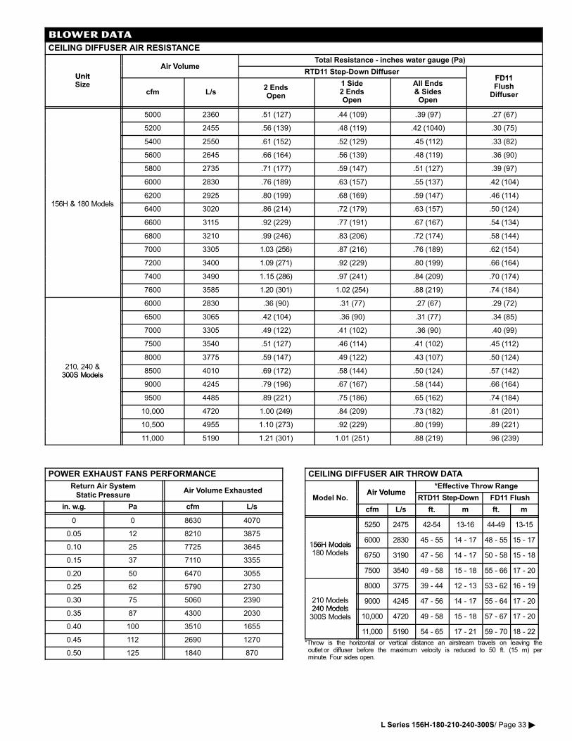
BLOWER DATA
CEILING DIFFUSER AIR RESISTANCE
Air VolumeTotal Resistance − inches water gauge (Pa)
Unit
Air VolumeRTD11 Step�Down Diffuser
FD11UnitSize
cfm L/s2 EndsOpen
1 Side2 EndsOpen
All Ends& SidesOpen
FD11Flush
Diffuser
5000 2360 .51 (127) .44 (109) .39 (97) .27 (67)
5200 2455 .56 (139) .48 (119) .42 (1040) .30 (75)
5400 2550 .61 (152) .52 (129) .45 (112) .33 (82)
5600 2645 .66 (164) .56 (139) .48 (119) .36 (90)
5800 2735 .71 (177) .59 (147) .51 (127) .39 (97)
6000 2830 .76 (189) .63 (157) .55 (137) .42 (104)
156H & 180 Models6200 2925 .80 (199) .68 (169) .59 (147) .46 (114)
156H & 180 Models6400 3020 .86 (214) .72 (179) .63 (157) .50 (124)
6600 3115 .92 (229) .77 (191) .67 (167) .54 (134)
6800 3210 .99 (246) .83 (206) .72 (174) .58 (144)
7000 3305 1.03 (256) .87 (216) .76 (189) .62 (154)
7200 3400 1.09 (271) .92 (229) .80 (199) .66 (164)
7400 3490 1.15 (286) .97 (241) .84 (209) .70 (174)
7600 3585 1.20 (301) 1.02 (254) .88 (219) .74 (184)
6000 2830 .36 (90) .31 (77) .27 (67) .29 (72)
6500 3065 .42 (104) .36 (90) .31 (77) .34 (85)
7000 3305 .49 (122) .41 (102) .36 (90) .40 (99)
7500 3540 .51 (127) .46 (114) .41 (102) .45 (112)
210 240 &
8000 3775 .59 (147) .49 (122) .43 (107) .50 (124)
210, 240 &300S Models
8500 4010 .69 (172) .58 (144) .50 (124) .57 (142)300S Models
9000 4245 .79 (196) .67 (167) .58 (144) .66 (164)
9500 4485 .89 (221) .75 (186) .65 (162) .74 (184)
10,000 4720 1.00 (249) .84 (209) .73 (182) .81 (201)
10,500 4955 1.10 (273) .92 (229) .80 (199) .89 (221)
11,000 5190 1.21 (301) 1.01 (251) .88 (219) .96 (239)
POWER EXHAUST FANS PERFORMANCE
Return Air System
Static PressureAir Volume Exhausted
in. w.g. Pa cfm L/s
0 0 8630 4070
0.05 12 8210 3875
0.10 25 7725 3645
0.15 37 7110 3355
0.20 50 6470 3055
0.25 62 5790 2730
0.30 75 5060 2390
0.35 87 4300 2030
0.40 100 3510 1655
0.45 112 2690 1270
0.50 125 1840 870
CEILING DIFFUSER AIR THROW DATA
Air Volume*Effective Throw Range
Model No.Air Volume
RTD11 Step�Down FD11 Flush
cfm L/s ft. m ft. m
5250 2475 42−54 13−16 44−49 13−15
156H Models6000 2830 45 − 55 14 − 17 48 − 55 15 − 17
156H Models180 Models 6750 3190 47 − 56 14 − 17 50 − 58 15 − 18
7500 3540 49 − 58 15 − 18 55 − 66 17 − 20
8000 3775 39 − 44 12 − 13 53 − 62 16 − 19
210 Models240 Models
9000 4245 47 − 56 14 − 17 55 − 64 17 − 20240 Models300S Models 10,000 4720 49 − 58 15 − 18 57 − 67 17 − 20
11,000 5190 54 − 65 17 − 21 59 − 70 18 − 22
*Throw is the horizontal or vertical distance an airstream travels on leaving theoutlet�or diffuser before the maximum velocity is reduced to 50 ft. (15 m) perminute. Four sides open.
L Series 156H−180−210−240−300S/ Page 33 �
GUIDE SPECIFICATIONS � ALL MODELSPrepared for the guidance of architects, consulting engineers andmechanical contractors.General � Furnish and install a single package air to air DX mechanicalcooling system, cooling and gas fired heating system or heat pump sys�tem, complete with automatic controls. The single package unit shall bea standard product of a firm regularly engaged in the manufacture of heat�ing�cooling equipment. The manufacturer shall have parts and serviceavailable throughout the U.S. and Canada.The installed weight shall not be more than lbs. (kg). Entire unit shallhave a width of not more than inches (mm), a depth of not more than inches (mm) and an overall height of not more than inches(mm). The equipment shall be shipped completely factory assembled, pre�charged, piped and wired internally ready for field connections. In addition,manufacturer shall test operate system at the factory before shipment.Air Distribution � Equipment shall be capable of bottom (down�flow) orside (horizontal) handling of conditioned air. Horizontal air shall require op�tional horizontal conversion kit. All air distribution ducts shall be fiberglassor ga. galvanized steel insulated with inch (mm) thick lb./ft.3 (kg/m3) density fiberglass or equivalent.Approvals � All electrical components shall have E.T.L. and C.G.A. List�ing. All wiring shall be in compliance with NEC and CEC.Equipment Warranty � Heat Exchangers shall have a limited warrantyfor a full ten years (LGA Models). Compressors have a limited warranty fora full five years. All other components have a limited warranty for one year.Refer to the Lennox Equipment Limited Warranty certificate included withthe unit for details.Cooling System � The total certified cooling capacity shall not be lessthan Btuh (kW) with an indoor coil air volume of cfm(L/s), an entering wet bulb air temperature of ³F (³C), an enteringdry bulb air temperature of ³F (³C) and an outdoor coil enteringtemperature of ³F (³C). The compressor power input shall notexceed kW at these conditions.The coils shall be non�ferrous construction with aluminum fins mechani�cally bonded to durable copper tubes. Coils shall be pressure leak tested.Coil face area shall be not less than sq. ft. (m2) (indoor coil) and sq. ft. (m2) (outdoor coil). Outdoor coils shall be slab coil construc�tion (LCA/LGA models) and formed coil construction (LHA models).Compressors shall be resiliently mounted, have overload protection andcrankcase heaters. The refrigeration system shall have discharge suctionand liquid line gauge ports, high pressure switches, low pressure switches,driers, freezestat, defrost control (LHA), check and expansion valves(LHA), reversing valves (LHA), accumulators (LHA) and full refrigerantcharge. Optional service valves shall be available (LCA/LGA only). Allmodels shall have low ambient operation down to 0³F (−17.7³C). All mod�els shall be rated in accordance with ARI Standards 340/360−93.Heating System (LGA Models) � The heating capacity output shall be Btuh (kW) with a gas input of Btuh (kW).Tubular heat exchanger and inshot type gas burners shall be constructedof aluminized steel. Controls shall consist of direct spark ignition, electron�ic flame sensor controls, flame rollout switch, limit controls and automaticredundant dual gas valve with staging control and combustion air provingswitch on induced draft blower. Unit shall be available for use with LPG/propane as an option. Heat exchanger shall be removable for servicing.Complete service access shall be provided for controls and wiring. Shallbe E.T.L./C.G.A. design certified for outdoor installation. Optional stainlesssteel heat exchanger shall be available for applications where mixed airtemperature is between 30 and 45³F (−1 and 7³C).Heating System (LHA Models) � The total certified heating capacity shallnot be less than Btuh (kW) with an indoor coil air volume of cfm (L/s), an entering dry bulb temperature of ³F (³C)and an outdoor coil entering air temperature of ³F (³C). The totalcompressor power input shall not exceed kW at the above conditions.Cabinet � Shall be galvanized steel with a powdered enamel paint finishelectrostatically bonded to the metal. Cabinet panels where conditioned airis handled shall be fully insulated to prevent sweating and minimize sound.Openings shall be provided for power connection entry. Indoor coil conden�sate drain extended outside cabinet shall be provided. Lifting holes shall beprovided for rigging. Bottom power and gas (LGA) entry shall be furnished.Service Access � Cabinet panels shall be hinged with tool�less access forcompressor/heating/controls, blower and air filter/economizer compartments.Supply Air Blower � Centrifugal supply air blower shall have ball bear�ings and adjustable belt drive. Blower assembly shall slide out of unit forservicing. Motor mount base shall permit ease of motor changeover andbelt tension adjustment. Blower wheel shall be statically and dynamicallybalanced. Blower shall be capable of delivering cfm (L/s) at anexternal static pressure of inches water gauge (Pa) requiring bhp (W) and rpm.Integrated Modular Control (IMC) � Solid state control board shall beprovided to operate unit. Built−in functions shall include: blower on/offdelay, built−in control parameter defaults, service relay output, dirty filterswitch input, dehumidistat input, economizer control, electric heat staging,ETM compatible, unit diagnosis, diagnostics code storage, gas valvedelay between stages, indoor air quality input, low ambient controls, mini�mum run time, night setback mode, smoke alarm mode, low pressure con�trol, thermostat bounce delay, three digit display, ³F or ³C display, 2 stageheat/3 stage cool thermostat compatible and warm up mode.Outdoor Coil Fans � Direct drive propeller type outdoor coil fans shalldischarge vertically and be direct driven by a hp (W) motor. Fanmotor shall have ball bearings and be permanently lubricated and inher�ently protected. Fans shall have a safety guard.Air Filters � Disposable 2 inch (51 mm) thick pleated filters furnishedshall have not less than sq. ft. (m2) of free area.
OPTIONAL ACCESSORIESAdditive Electric Heaters (LCA/LHA Models) � The certified total heat�ing capacity output shall be Btuh with kW input at volts power supply.Electric heaters shall be available for factory or field installation. Heating ele�ments shall be nichrome bare wire exposed directly to the air stream. Time de�lays shall bring the elements on and off in sequence with a time delay betweeneach element. Limit controls shall provide overload and short circuit protection.Blower Proving Switch � Furnish and factory install air pressure switchto monitor blower operation.Ceiling Diffusers � Furnish and install a (flush or stepdown) optionalcombination ceiling supply and return air diffuser. It shall be capable of notless than ft. (m) radius of effective throw. Supply and return transi�tions shall be available, for field installation in the roof mounting frame, toprovide duct connection to the diffuser.Coil Guards � Furnish and install galvanized steel coil guards.Control Systems � Shall provide a selection of control systems to auto�matically operate the mechanical equipment through the heating or cool�ing and ventilating cycles as required.Corrosion Protection � Furnish and factory apply phenolic epoxy coatingto either or both of the following: Outdoor coils with painted outdoor base sec�tion. Indoor coil with painted indoor base section and painted blower housings.Dehumidistat � Furnish and install dehumidistat, relays information toIntegrated Modular Control.Dirty Filter Switch � Furnish and install pressure switch that indicatesdirty filter, relays information to Integrated Modular Control.Disconnect � Furnish and factory install unit disconnect switch.Economizer Section � Furnish and install economizer complete with recir�culated air dampers, outside air dampers and controls. Low leakage dampersshall ride in nylon bearings. The economizer section shall provide for theintroduction of outdoor air for minimum ventilation and free cooling. Integratedeconomizer control shall allow compressors to cycle for additional cooling, asneeded. Damper actuator shall be opposing gear driven, 24 volt, fully modu�lating design. Plug�in control board (on unit IMC board) shall consist of adjust�able minimum positioner, enthalpy setpoint and DIP switches for setting typeof control logic used. Economizer control options shall consist of sensibletemperature, global, outdoor enthalpy and differential enthalpy (outdoor andreturn air). Optional outdoor air hood (required) with filters shall be galvanizedsteel with a powdered enamel paint finish electrostatically bonded to the met�al. Economizer shall be available for factory or field installation.Gravity Exhaust Dampers � Pressure operated dampers shall be avail�able for factory or field installation. Extruded aluminum dampers shall pre�vent blow�back and outdoor air infiltration during off cycle. Optional hoodshall be available.Grille Guards � Furnish and install heavy gauge guards, shall protect thespace between the outdoor coils and the main unit.Hail Guards � Furnish and install heavy gauge, painted steel hail guards.High Efficiency Blower Motor � Furnish and factory install high efficiencyblower motor.Horizontal Conversion Kit � Shall be available for all models to provideduct covers to block off unit down−flow supply air opening, horizontal re�turn air opening panel (on unit) is moved to block off down−flow return airopening for horizontal applications.Horizontal Gravity Exhaust Dampers � Pressure operated dampersshall be available for field installation in the return air duct. Extruded alumi�num dampers shall prevent blow�back and outdoor air infiltration during offcycle.Indoor Air Quality Sensor � Furnish and field install sensor to monitorCO2 levels, relays information to Integrated Module Control which adjustseconomizer dampers proportionately to the pollutant level.Outdoor Air Damper Section � Optional outdoor dampers shall be avail�able to provide outdoor air requirements of up to 25%. Models shall beavailable for manual or automatic operation. Dampers shall be opposinggear driven design. Motorized damper section shall install internal to theunit. Optional outdoor air hood (required) with filters shall be galvanizedsteel with a powdered enamel paint finish electrostatically bonded to themetal. Dampers shall be available for factory or field installation.Power Exhaust Fan � Shall be available for all models with economizer(down�flow applications only). Direct drive propeller type fan shall exhaustair through optional gravity exhaust damper (required). Motor shall beoverload protected. Fan shall be factory or field installed between econo�mizer and gravity exhaust dampers.Roof Mounting Frame � Furnish and install a steel roof mounting framefor bottom discharge and return air duct connection. It shall mate to the bot�tom perimeter of the equipment. When flashed into the roof it shall makea unit mounting curb and provide weatherproof duct connection and entryinto the conditioned area. Height of frame shall be inches (mm).Flashing shall be the responsibility of the roofing contractor. Frame shallbe approved by U.S. National Roofing Contractors Association.Service Outlets � Furnish and factory install dual 115 volt, 15 amp GFCItype service outlets. Wiring shall be field provided.Service Valves (LCA/LGA) � Furnish and factory install fully serviceablebrass service valves in discharge and liquid lines. Shall allow refrigerantpump down to high side of system for servicing of low side.Smoke Detectors � Furnish and factory install photoelectric type smokedetector in either or both return air section and supply air section.Terminal Block (LCA/LHA Models) � Shall be required for units withoutdisconnect switch but with single point power supply and electric heat.Unit Fuse Block (LCA/LHA Models) � Shall be required for units withsingle point power supply and electric heat.
L Series 156H−180−210−240−300S/ Page 34 �
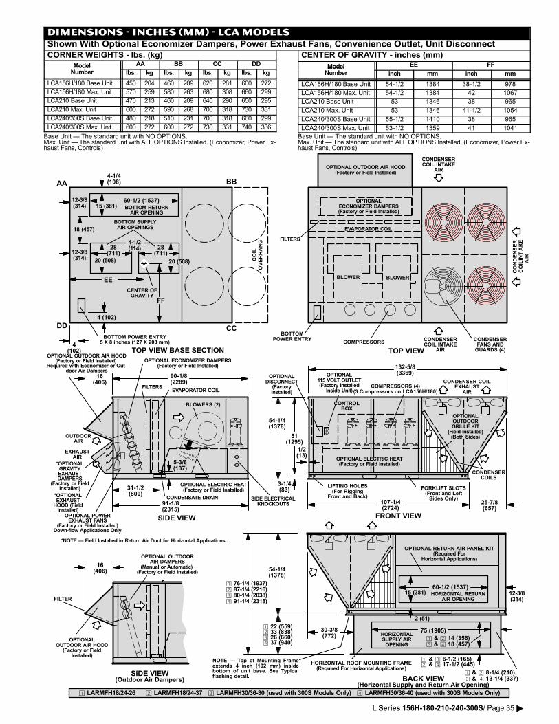
DIMENSIONS − INCHES (MM) − LCA MODELSShown With Optional Economizer Dampers, Power Exhaust Fans, Convenience Outlet, Unit DisconnectCORNER WEIGHTS − lbs. (kg)
Model AA BB CC DDModelNumber lbs. kg lbs. kg lbs. kg lbs. kg
LCA156H/180 Base Unit 450 204 460 209 620 281 600 272
LCA156H/180 Max. Unit 570 259 580 263 680 308 660 299
LCA210 Base Unit 470 213 460 209 640 290 650 295
LCA210 Max. Unit 600 272 590 268 700 318 730 331
LCA240/300S Base Unit 480 218 510 231 700 318 660 299
LCA240/300S Max. Unit 600 272 600 272 730 331 740 336
Base Unit � The standard unit with NO OPTIONS.Max. Unit � The standard unit with ALL OPTIONS Installed. (Economizer, Power Ex�haust Fans, Controls)
CENTER OF GRAVITY − inches (mm)
Model EE FFModelNumber inch mm inch mm
LCA156H/180 Base Unit 54�1/2 1384 38−1/2 978
LCA156H/180 Max. Unit 54�1/2 1384 42 1067
LCA210 Base Unit 53 1346 38 965
LCA210 Max. Unit 53 1346 41�1/2 1054
LCA240/300S Base Unit 55�1/2 1410 38 965
LCA240/300S Max. Unit 53�1/2 1359 41 1041
Base Unit � The standard unit with NO OPTIONS.Max. Unit � The standard unit with ALL OPTIONS Installed. (Economizer, Power Ex�haust Fans, Controls)
BOTTOM POWER ENTRY5 X 8 inches (127 X 203 mm)
BOTTOM SUPPLYAIR OPENINGS
COIL
OVERHANG
BOTTOM RETURNAIR OPENING
4�1/4(108)
4�1/2(114) 28
(711)28
(711)
4 (102)
4(102)
12�3/8(314)
12�3/8(314) 20 (508) 20 (508)
15 (381)
18 (457)
60�1/2 (1537)
AA BB
CCDD
CENTER OFGRAVITY
EE
FF
BLOWERS (2)
EVAPORATOR COIL
CONDENSERCOIL INTAKE
AIR
CONDENSERCOILS
BOTTOMPOWER ENTRY
FILTERS
CONDENSERCOIL INTAKE
AIR
COMPRESSORS
CONTROLBOX
CONDENSER COILEXHAUST
AIR
CONDENSERFANS ANDGUARDS (4)
BLOWER
EVAPORATOR COIL
FILTERS
BLOWER
FRONT VIEW
TOP VIEW
SIDE VIEW
90�1/8(2289)
31�1/2(800)
91�1/8(2315)
3�1/4(83)
107�1/4(2724)
132�5/8(3369)
54�1/4(1378)
51(1295)
LIFTING HOLES(For Rigging
Front and Back)
TOP VIEW BASE SECTION
16(406)
CONDENSATE DRAIN
1/2(13)
CONDENSER
COIL IN
TAKE
AIR
BACK VIEW(Horizontal Supply and Return Air Opening)
HORIZONTALSUPPLY AIROPENING
HORIZONTAL ROOF MOUNTING FRAME(Required For Horizontal Applications)
� & � 8�1/4 (210)� & � 13�1/4 (337)
75 (1905)
OUTDOORAIR
OPTIONAL ECONOMIZER DAMPERS(Factory or Field Installed)
OPTIONALECONOMIZER DAMPERS(Factory or Field Installed)
COMPRESSORS (4)(3 Compressors on LCA156H/180)
FORKLIFT SLOTS(Front and LeftSides Only)
OPTIONAL ELECTRIC HEAT(Factory or Field Installed)
OPTIONALDISCONNECT
(FactoryInstalled)
SIDE ELECTRICALKNOCKOUTS
5�3/8(137)
OPTIONAL ELECTRIC HEAT(Factory or Field Installed)
HORIZONTAL RETURNAIR OPENING
12�3/8(314)
15 (381)60�1/2 (1537)
2 (51)
54�1/4(1378)
*NOTE � Field Installed in Return Air Duct for Horizontal Applications.
OPTIONAL OUTDOOR AIR HOOD(Factory or Field Installed)
Required with Economizer or Out�door Air Dampers
NOTE � Top of Mounting Frameextends 4 inch (102 mm) insidebottom of unit base. See Typicalflashing detail.
OPTIONAL OUTDOOR AIR HOOD(Factory or Field Installed)
OPTIONAL115 VOLT OUTLET(Factory Installed
Inside Unit)
OPTIONAL RETURN AIR PANEL KIT(Required For
Horizontal Applications)
� & � 6�1/2 (165)� & � 17�1/2 (445)
� 22 (559)� 33 (838)� 26 (660)� 37 (940)
25�7/8(657)
16(406)
OPTIONALOUTDOOR AIR HOOD
(Factory or FieldInstalled)
OPTIONAL OUTDOORAIR DAMPERS
(Manual or Automatic) (Factory or Field Installed)
SIDE VIEW(Outdoor Air Dampers)
� 76�1/4 (1937)� 87�1/4 (2216)� 80�1/4 (2038)� 91�1/4 (2318)
� & � 14 (356)� & � 18 (457)
� LARMFH18/24�26 � LARMFH18/24�37 � LARMFH30/36�30 (used with 300S Models Only) � LARMFH30/36�40 (used with 300S Models Only)
30�3/8(772)
OPTIONALOUTDOORGRILLE KIT
(Field Installed)(Both Sides)
*OPTIONALGRAVITYEXHAUSTDAMPERS
(Factory or FieldInstalled)
OPTIONAL POWEREXHAUST FANS
(Factory or Field Installed)Down�flow Applications Only
*OPTIONALEXHAUST
HOOD (FieldInstalled)
EXHAUSTAIR
FILTER
L Series 156H−180−210−240−300S/ Page 35 �
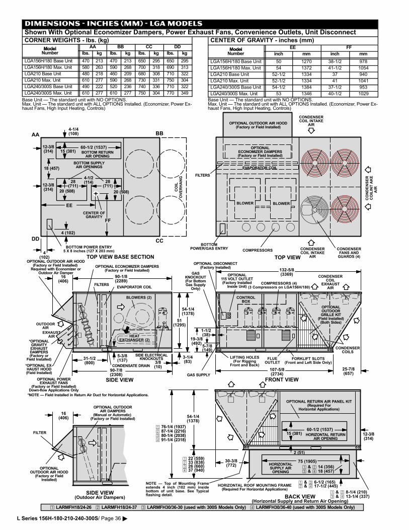
DIMENSIONS − INCHES (MM) − LGA MODELSShown With Optional Economizer Dampers, Power Exhaust Fans, Convenience Outlets, Unit DisconnectCORNER WEIGHTS − lbs. (kg)
Model AA BB CC DDModelNumber lbs. kg lbs. kg lbs. kg lbs. kg
LGA156H/180 Base Unit 470 213 470 213 650 295 650 295
LGA156H/180 Max. Unit 580 263 590 268 700 318 690 313
LGA210 Base Unit 480 218 460 209 680 308 710 322
LGA210 Max. Unit 610 277 590 268 730 331 750 304
LGA240/300S Base Unit 490 222 520 236 740 336 710 322
LGA240/300S Max. Unit 610 277 610 277 750 304 770 349
Base Unit � The standard unit with NO OPTIONS.Max. Unit � The standard unit with ALL OPTIONS Installed. (Economizer, Power Ex�haust Fans, High Input Heating, Controls)
CENTER OF GRAVITY − inches (mm)
Model EE FFModelNumber inch mm inch mm
LGA156H/180 Base Unit 50 1270 38−1/2 978
LGA156H/180 Max. Unit 54 1372 41�1/2 1054
LGA210 Base Unit 52�1/2 1334 37 940
LGA210 Max. Unit 52�1/2 1334 41 1041
LGA240/300S Base Unit 54�1/2 1384 37�1/2 953
LGA240/300S Max. Unit 53 1346 40�1/2 1029
Base Unit � The standard unit with NO OPTIONS.Max. Unit � The standard unit with ALL OPTIONS Installed. (Economizer, Power Ex�haust Fans, High Input Heating, Controls)
BOTTOM POWER ENTRY5 X 8 inches (127 X 203 mm)
BOTTOM SUPPLYAIR OPENINGS
COIL
OVERHANG
BOTTOM RETURNAIR OPENING
4�1/4(108)
4�1/2(114) 28
(711)28
(711)
4 (102)
4(102)
12�3/8(314)
12�3/8(314) 20 (508) 20 (508)
15 (381)
18 (457)
60�1/2 (1537)
AA BB
CCDD
CENTER OFGRAVITY
EE
FF
TOP VIEW BASE SECTION
*OPTIONALGRAVITYEXHAUSTDAMPERS(Factory or
Field Installed)
OPTIONAL POWEREXHAUST FANS
(Factory or Field Installed)Down�flow Applications Only
*OPTIONAL EX�HAUST HOOD(Field Installed)
EXHAUSTAIR HEAT
EXCHANGER (2)
BLOWERS (2)
COMPRESSORS (4)(3 Compressors on LGA156H/180)EVAPORATOR COIL
CONDENSERCOIL INTAKE
AIR
CONDENSERCOILS
BOTTOMPOWER/GAS ENTRY
FILTERS
CONDENSERCOIL INTAKE
AIR
COMPRESSORS
CONTROLBOX
CONDENSERCOIL
EXHAUSTAIR
CONDENSERFANS ANDGUARDS (4)
BLOWER
EVAPORATOR COIL
FILTERS
BLOWER
FRONT VIEW
TOP VIEW
SIDE VIEW
FORKLIFT SLOTS(Front and Left Side Only)
OUTDOORAIR
90�1/8(2289)
31�1/2(800)
132�5/8(3369)
LIFTING HOLES(For Rigging
Front and Back)
OPTIONAL ECONOMIZER DAMPERS(Factory or Field Installed)
16(406)
CONDENSATE DRAIN
5�3/8(137)
CONDENSER
COIL IN
TAKE
AIR
OPTIONAL OUTDOOR AIR HOOD(Factory or Field Installed)
Required with Economizer orOutdoor Air Damper
OPTIONALECONOMIZER DAMPERS(Factory or Field Installed)
OPTIONAL DISCONNECT(Factory Installed)
OPTIONAL OUTDOOR AIR HOOD(Factory or Field Installed)
OPTIONAL115 VOLT OUTLET(Factory Installed
Inside Unit)
FLUEOUTLET3/8
(10)
3�1/4(83)
54�1/4(1378)
51(1295)
GASKNOCKOUT(For BottomGas Supply
Only)
GAS SUPPLY
5�7/8(149)
19�3/8(492)
1�1/2(38)
90�7/8(2308)
107�5/8(2734)
SIDE ELECTRICALKNOCKOUTS
25�7/8(657)
BACK VIEW(Horizontal Supply and Return Air Opening)
HORIZONTALSUPPLY AIROPENING
HORIZONTAL ROOF MOUNTING FRAME(Required For Horizontal Applications)
� & � 8�1/4 (210)� & � 13�1/4 (337)
75 (1905)
HORIZONTAL RETURNAIR OPENING
12�3/8(314)
15 (381)60�1/2 (1537)
2 (51)
54�1/4(1378)
NOTE � Top of Mounting Frameextends 4 inch (102 mm) insidebottom of unit base. See Typicalflashing detail.
OPTIONAL RETURN AIR PANEL KIT(Required For
Horizontal Applications)
� & � 6�1/2 (165)� & � 17�1/2 (445)
� 22 (559)� 33 (838)� 26 (660)� 37 (940)
16(406)
OPTIONALOUTDOOR AIR HOOD
(Factory or FieldInstalled)
OPTIONAL OUTDOORAIR DAMPERS
(Manual or Automatic) (Factory or Field Installed)
SIDE VIEW(Outdoor Air Dampers)
� 76�1/4 (1937)� 87�1/4 (2216)� 80�1/4 (2038)� 91�1/4 (2318)
� & � 14 (356)� & � 18 (457)
� LARMFH18/24�26 � LARMFH18/24�37 � LARMFH30/36�30 (used with 300S Models Only) � LARMFH30/36�40 (used with 300S Models Only)
30�3/8(772)
OPTIONALOUTDOORGRILLE KIT
(Field Installed)(Both Sides)
*NOTE � Field Installed in Return Air Duct for Horizontal Applications.
FILTER
L Series 156H−180−210−240−300S/ Page 36 �
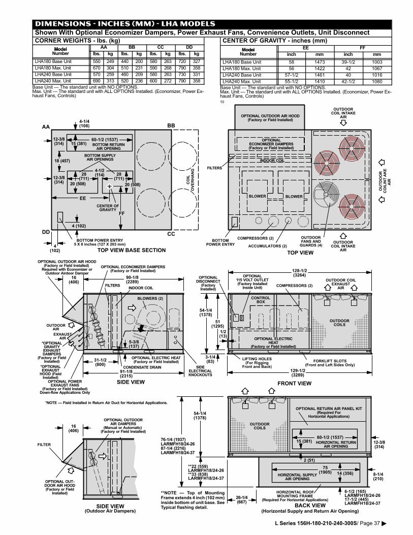
DIMENSIONS − INCHES (MM) − LHA MODELSShown With Optional Economizer Dampers, Power Exhaust Fans, Convenience Outlets, Unit DisconnectCORNER WEIGHTS − lbs. (kg)
Model AA BB CC DDModelNumber lbs. kg lbs. kg lbs. kg lbs. kg
LHA180 Base Unit 550 249 440 200 580 263 720 327
LHA180 Max. Unit 670 304 510 231 590 268 790 358
LHA240 Base Unit 570 259 460 209 580 263 730 331
LHA240 Max. Unit 690 313 520 236 600 272 790 358
Base Unit � The standard unit with NO OPTIONS.Max. Unit � The standard unit with ALL OPTIONS Installed. (Economizer, Power Ex�haust Fans, Controls)
CENTER OF GRAVITY − inches (mm)
Model EE FFModelNumber inch mm inch mm
LHA180 Base Unit 58 1473 39�1/2 1003
LHA180 Max. Unit 56 1422 42 1067
LHA240 Base Unit 57�1/2 1461 40 1016
LHA240 Max. Unit 55�1/2 1410 42�1/2 1080
Base Unit � The standard unit with NO OPTIONS.Max. Unit � The standard unit with ALL OPTIONS Installed. (Economizer, Power Ex�haust Fans, Controls)10
BOTTOM POWER ENTRY5 X 8 inches (127 X 203 mm)
BOTTOM SUPPLYAIR OPENINGS
COIL
OVERHANG
BOTTOM RETURNAIR OPENING
4�1/4(108)
4�1/2(114) 28
(711)28
(711)
4 (102)
4(102)
12�3/8(314)
12�3/8(314) 20 (508) 20 (508)
15 (381)
18 (457)
60�1/2 (1537)
AA BB
CCDD
CENTER OFGRAVITY
EE
FF
TOP VIEW BASE SECTION
*OPTIONALGRAVITYEXHAUSTDAMPERS
(Factory or FieldInstalled)
OPTIONAL POWEREXHAUST FANS
(Factory or Field Installed)Down�flow Applications Only
*OPTIONALEXHAUST
HOOD (FieldInstalled)
EXHAUSTAIR
BLOWERS (2)
COMPRESSORS (2)INDOOR COIL
OUTDOORCOIL INTAKE
AIR
OUTDOORCOILS
BOTTOMPOWER ENTRY
FILTERS
OUTDOORCOIL INTAKE
AIR
COMPRESSORS (2)
CONTROLBOX
OUTDOOR COILEXHAUST
AIR
OUTDOORFANS ANDGUARDS (4)
BLOWER
INDOOR COIL
FILTERS
BLOWER
FRONT VIEW
TOP VIEW
SIDE VIEW
90�1/8(2289)
31�1/2(800)
91�1/8(2315)
3�1/4(83)
129�1/2(3289)
128�1/2(3264)
54�1/4(1378)
51(1295)
LIFTING HOLES(For Rigging
Front and Back)
16(406)
CONDENSATE DRAIN
1/2(13)
5�3/8(137)
OUTDOOR
COIL IN
TAKE
AIR
ACCUMULATORS (2)
OPTIONALDISCONNECT
(FactoryInstalled)
SIDEELECTRICALKNOCKOUTS
OUTDOORAIR
OPTIONAL ECONOMIZER DAMPERS(Factory or Field Installed)
OPTIONALECONOMIZER DAMPERS(Factory or Field Installed)
FORKLIFT SLOTS(Front and Left Sides Only)
OPTIONAL ELECTRICHEAT
(Factory or Field Installed)
OPTIONAL ELECTRIC HEAT(Factory or Field Installed)
BACK VIEW(Horizontal Supply and Return Air Opening)
HORIZONTAL SUPPLYAIR OPENING
HORIZONTAL ROOFMOUNTING FRAME
(Required For Horizontal Applications)
8�1/4(210)
75(1905) 14 (356)
HORIZONTAL RETURNAIR OPENING
12�3/8(314)
15 (381)60�1/2 (1537)
2 (51)
OUTDOORCOILS
54�1/4(1378)
OPTIONAL OUTDOOR AIR HOOD(Factory or Field Installed)
Required with Economizer orOutdoor Airdoor Damper
OPTIONAL OUTDOOR AIR HOOD(Factory or Field Installed)
*NOTE � Field Installed in Return Air Duct for Horizontal Applications.
OPTIONAL115 VOLT OUTLET(Factory Installed
Inside Unit)
OPTIONAL RETURN AIR PANEL KIT(Required For
Horizontal Applications)
**NOTE � Top of MountingFrame extends 4 inch (102 mm)inside bottom of unit base. SeeTypical flashing detail.
16(406)
OPTIONAL OUT�DOOR AIR HOOD(Factory or Field
Installed)
OPTIONAL OUTDOORAIR DAMPERS
(Manual or Automatic) (Factory or Field Installed)
SIDE VIEW(Outdoor Air Dampers)
6�1/2 (165)LARMFH18/24�2617�1/2 (445)LARMFH18/24�37
**22 (559)LARMFH18/24�26**33 (838)LARMFH18/24�37
76�1/4 (1937)LARMFH18/24�2687�1/4 (2216)LARMFH18/24�37
26�1/4(667)
FILTER
L Series 156H−180−210−240−300S/ Page 37 �
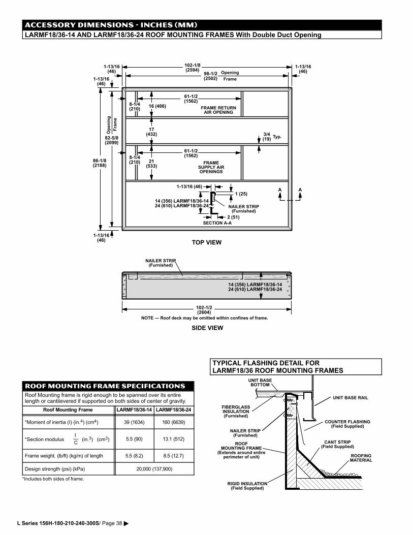
ACCESSORY DIMENSIONS − INCHES (MM)
LARMF18/36−14 AND LARMF18/36−24 ROOF MOUNTING FRAMES With Double Duct Opening
1 (25)
2 (51)
SECTION A�A
1�13/16 (46)
NOTE � Roof deck may be omitted within confines of frame.
SIDE VIEW
NAILER STRIP(Furnished)
14 (356) LARMF18/36�1424 (610) LARMF18/36�24
FRAME RETURNAIR OPENING
FRAMESUPPLY AIROPENINGS
TOP VIEW
Frame
Opening
Frame
Opening
17(432)
21(533)
16 (406)
102�1/8(2594)
8�1/4(210)
61�1/2(1562)
61�1/2(1562)
8�1/4(210)
98�1/2(2502)
86�1/8(2188)
82�5/8(2099)
102�1/2(2604)
1�13/16(46)
AA
NAILER STRIP(Furnished)
3/4(19)
Typ.
14 (356) LARMF18/36�1424 (610) LARMF18/36�24
1�13/16(46)
1�13/16(46)
1�13/16(46)
ROOF MOUNTING FRAME SPECIFICATIONS
Roof Mounting frame is rigid enough to be spanned over its entirelength or cantilevered if supported on both sides of center of gravity.
Roof Mounting Frame LARMF18/36�14 LARMF18/36�24
*Moment of inertia (I) (in.4) (cm4) 39 (1634) 160 (6639)
*Section modulusI�C
(in.3) (cm3) 5.5 (90) 13.1 (512)
Frame weight. (lb/ft) (kg/m) of length 5.5 (8.2) 8.5 (12.7)
Design strength (psi) (kPa) 20,000 (137,900)
*Includes both sides of frame.
TYPICAL FLASHING DETAIL FORLARMF18/36 ROOF MOUNTING FRAMES
ROOFMOUNTING FRAME
(Extends around entireperimeter of unit)
FIBERGLASSINSULATION(Furnished)
COUNTER FLASHING(Field Supplied)
UNIT BASEBOTTOM
RIGID INSULATION(Field Supplied)
ROOFINGMATERIAL
CANT STRIP(Field Supplied)
NAILER STRIP(Furnished)
UNIT BASE RAIL
L Series 156H−180−210−240−300S/ Page 38 �
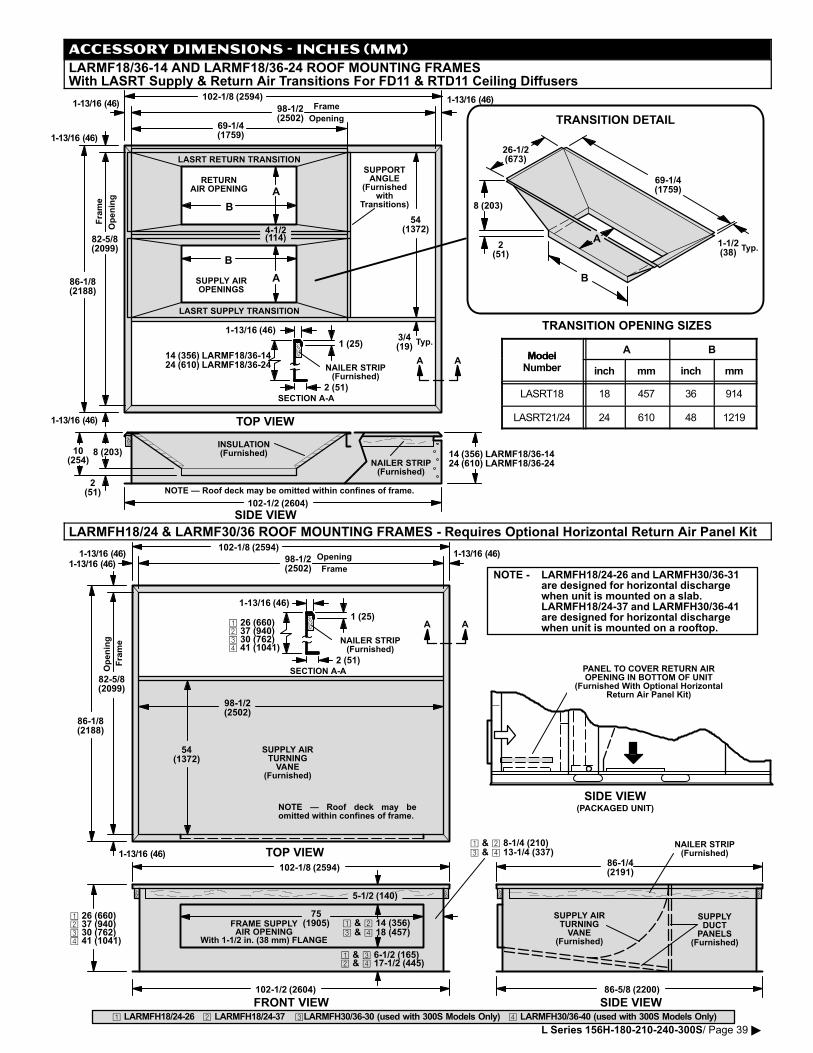
1 (25)
2 (51)SECTION A�A
1�13/16 (46)
SIDE VIEW
NAILER STRIP(Furnished)
RETURNAIR OPENING
SUPPLY AIROPENINGS
TOP VIEW
Frame
Opening
Frame
Opening
54(1372)
102�1/8 (2594)
69�1/4(1759)
98�1/2(2502)
86�1/8(2188)
82�5/8(2099)
102�1/2 (2604)
AANAILER STRIP(Furnished)
3/4(19)
Typ.
4�1/2(114)
LASRT RETURN TRANSITION
LASRT SUPPLY TRANSITION
SUPPORTANGLE
(Furnishedwith
Transitions)
INSULATION(Furnished)
2(51)
10(254)
8 (203)
A
B
B
A
14 (356) LARMF18/36�1424 (610) LARMF18/36�24
14 (356) LARMF18/36�1424 (610) LARMF18/36�24
A
B
69�1/4(1759)
2(51)
8 (203)
26�1/2(673)
1�1/2(38)
Typ.
TRANSITION OPENING SIZES
NOTE � Roof deck may be omitted within confines of frame.
TRANSITION DETAIL
1�13/16 (46)
1�13/16 (46)
1�13/16 (46) 1�13/16 (46)
ACCESSORY DIMENSIONS − INCHES (MM)
LARMF18/36−14 AND LARMF18/36−24 ROOF MOUNTING FRAMESWith LASRT Supply & Return Air Transitions For FD11 & RTD11 Ceiling Diffusers
ModelA B
ModelNumber inch mm inch mm
LASRT18 18 457 36 914
LASRT21/24 24 610 48 1219
LARMFH18/24 & LARMF30/36 ROOF MOUNTING FRAMES − Requires Optional Horizontal Return Air Panel Kit
� LARMFH18/24�26 � LARMFH18/24�37 �LARMFH30/36�30 (used with 300S Models Only) � LARMFH30/36�40 (used with 300S Models Only)
102�1/8 (2594)
SIDE VIEW
TOP VIEW
Frame
Opening
Frame
Opening
54(1372)
98�1/2(2502)
82�5/8(2099)
86�5/8 (2200)
98�1/2(2502)
FRONT VIEW
NAILER STRIP(Furnished)
102�1/2 (2604)
FRAME SUPPLYAIR OPENING
With 1�1/2 in. (38 mm) FLANGE
75(1905)
5�1/2 (140)
SUPPLYDUCT
PANELS(Furnished)
SUPPLY AIRTURNINGVANE
(Furnished)
1 (25)
2 (51)SECTION A�A
1�13/16 (46)
NAILER STRIP(Furnished)
AA
102�1/8 (2594)86�1/4(2191)
NOTE � Roof deck may beomitted within confines of frame.
SUPPLY AIRTURNINGVANE
(Furnished)
PANEL TO COVER RETURN AIROPENING IN BOTTOM OF UNIT
(Furnished With Optional HorizontalReturn Air Panel Kit)
SIDE VIEW(PACKAGED UNIT)
86�1/8(2188)
1�13/16 (46)
1�13/16 (46)1�13/16 (46)1�13/16 (46)
NOTE − LARMFH18/24�26 and LARMFH30/36�31are designed for horizontal dischargewhen unit is mounted on a slab.LARMFH18/24�37 and LARMFH30/36�41are designed for horizontal dischargewhen unit is mounted on a rooftop.
� & � 8�1/4 (210)� & � 13�1/4 (337)
� & � 6�1/2 (165)� & � 17�1/2 (445)
� 26 (660)� 37 (940)� 30 (762)� 41 (1041)
� & � 14 (356)� & � 18 (457)
� 26 (660)� 37 (940)� 30 (762)� 41 (1041)
L Series 156H−180−210−240−300S/ Page 39 �
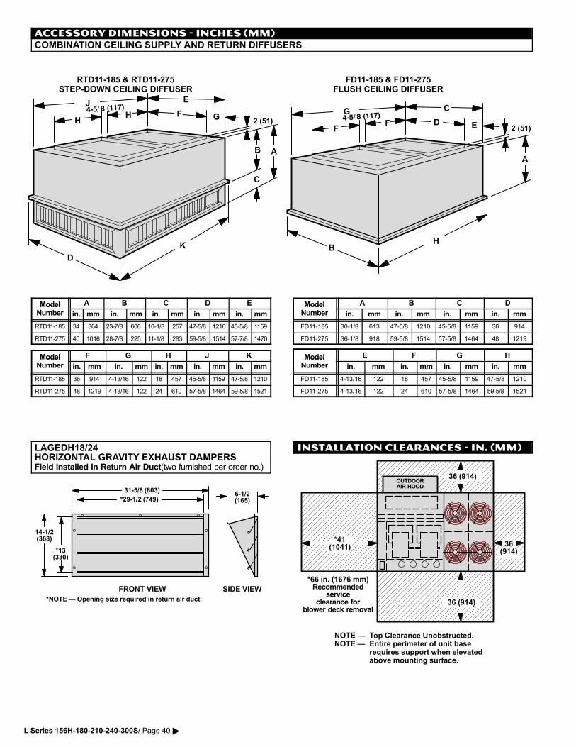
ACCESSORY DIMENSIONS − INCHES (MM)COMBINATION CEILING SUPPLY AND RETURN DIFFUSERS
2 (51)2 (51)
AB
C
D
E
F G
A
B
C
D
E
RTD11�185 & RTD11�275STEP�DOWN CEILING DIFFUSER
FD11�185 & FD11�275FLUSH CEILING DIFFUSER
HH
J
K
FF
G
H
Model A B C D EModelNumber in. mm in. mm in. mm in. mm in. mm
RTD11�185 34 864 23�7/8 606 10�1/8 257 47�5/8 1210 45�5/8 1159
RTD11�275 40 1016 28�7/8 225 11�1/8 283 59�5/8 1514 57�7/8 1470
Model F G H J KModelNumber in. mm in. mm in. mm in. mm in. mm
RTD11�185 36 914 4�13/16 122 18 457 45�5/8 1159 47�5/8 1210
RTD11�275 48 1219 4�13/16 122 24 610 57�5/8 1464 59�5/8 1521
Model A B C DModelNumber in. mm in. mm in. mm in. mm
FD11�185 30�1/8 613 47�5/8 1210 45�5/8 1159 36 914
FD11�275 36�1/8 918 59�5/8 1514 57�5/8 1464 48 1219
Model E F G HModelNumber in. mm in. mm in. mm in. mm
FD11�185 4�13/16 122 18 457 45�5/8 1159 47�5/8 1210
FD11�275 4�13/16 122 24 610 57�5/8 1464 59�5/8 1521
LAGEDH18/24HORIZONTAL GRAVITY EXHAUST DAMPERSField Installed In Return Air Duct(two furnished per order no.)
FRONT VIEW SIDE VIEW
31�5/8 (803)
14�1/2(368)
*13(330)
6�1/2(165)*29�1/2 (749)
*NOTE � Opening size required in return air duct.
INSTALLATION CLEARANCES − IN. (MM)
OUTDOORAIR HOOD
36 (914)
36(914)
36 (914)
*41(1041)
NOTE � Top Clearance Unobstructed.NOTE � Entire perimeter of unit base
requires support when elevatedabove mounting surface.
*66 in. (1676 mm)Recommended
serviceclearance for
blower deck removal
L Series 156H−180−210−240−300S/ Page 40 �