packetcable and event message guide - cisco.com€¦ · 3 packetcable and event message...
TRANSCRIPT

PacketCable and Event Message Provisioning and Operations Guide, Cisco BTS 10200 Softswitch, Release 5.0
Revised: May 2010, OL-12264-08
This document describes how the Cisco BTS 10200 Softswitch implements PacketCable-based interfaces and functions. It also provides provisioning and operating information for PacketCable features and event messages (EMs). It is intended for use by service provider management, system administration, and engineering personnel who are responsible for designing, installing, provisioning, and maintaining networks that use the Cisco BTS 10200 Softswitch system in a PacketCable-based network.
Feature History
Release Modification
Release 5.0
Version OL-12264-08:
• Updated the “Event Message Transport” section on page 10.
Release 5.0
Version OL-12264-07:
• Updated the Reset, Control, and Status Commands section.
Americas Headquarters:
© 2007 Cisco Systems, Inc. All rights reserved.
Cisco Systems, Inc., 170 West Tasman Drive, San Jose, CA 95134-1706 USA

Release 5.0
Version OL-12264-06:
• Release 5.0 MR1 and Release 5.0 MR2— The CMTS Discovery Using the Static Subnet Table feature was implemented in Release 5.0 MR1 of the BTS 10200. Release 5.0 MR2 added enhancements to the CMTS Discovery Using the Static Subnet Table feature.
• Release 5.0—The Aggregation ID Subnet feature enables a service provider to use the Subnet table to statically configure all subnets handled by every Cable Modem Termination System (CMTS). The Cisco BTS 10200 Softswitch uses the IP address of the embedded Multimedia Terminal Adapter (eMTA) and Subnet table to determine the CMTS handling of a particular eMTA. An eMTA is a residential gateway. A CMTS is an aggregation device for multiple eMTAs.
Release 5.0
Version OL-12264-05:
• Release 5.0—The dqos-supp field is moved from the aggr table to the aggr-profile table. For DQoS to take effect, the aggr entry must be provisioned with an aggr-profile-id, and the aggr-profile entry must have dqos-supp=Y. See Provisioning the CMS Interfaces to the CMTS and eMTA, page 18.
• Release 5.0, Maintenance Release 1—The QoS entry must have client-type=DQoS for DQoS features to be applied. See Provisioning DQoS Parameters for Codec Negotiation Service, page 21 and Provisioning TGCP Interfaces to TGWs, page 22.
• Release 5.0—Added details regarding parameter BEST_EFFORT_ON_QOS_FAIL in ca-config table. See the status commands in the “Reset, Control, and Status Commands” section on page 57.
Version OL-12264-04:
• Additional information was added for the reset command. See Reset, Control, and Status Commands, page 57.
2PacketCable and Event Message Provisioning and Operations Guide, Cisco BTS 10200 Softswitch, Release 5.0
OL-12264-08
Release Modification
Release 5.0
Version OL-12264-03:
• PCMM provisioning steps were corrected, including the requirement to change the call-agent-profile parameter pcmm-supp to Y. See Provisioning PCMM-Based QoS for Type 1 Clients, page 53.
Version OL-12264-02:
• The EM attributes, calling party NP source and called party NP source, were added, These are in addition to the following attributes that were included in version OL-12264-01 of this document: jurisdiction information parameter (JIP), account code, authorization code, ported-in calling number, ported-in called number, and billing type (flat rate or measured rate). See EM Content, page 72.
• The EM billing specification reference was changed from PKT-SP-EM-I07-030815 to PKT-SP-EM-I10-040721 (Industry Standards, page 76, and throughout the document). The Cisco BTS 10200 Softswitch complies with the RKS EM billing interface requirements of PKT-SP-EM-I10-040721.
• The reference for EM billing file naming was changed from PKT-SP-EM-I07-030815 to EM-N-04.0186-3 (Industry Standards, page 76, and throughout the document).
• References to PKT-SP-EM1.5-I02-050812 were changed to PKT-SP-EM-I10-040721.
Version OL-12264-01:
• This document includes all of the information contained in the Release 4.5.x version, along with information for all Release 5.0 features. New information for Release 5.0 is summarized in the list below.
• The “Measurements” section was updated with a link to the measurements information in the Cisco BTS 10200 Softswitch Operations and Maintenance Guide.
• The “Events and Alarms” section was updated with a link to the measurements information in the Cisco BTS 10200 Softswitch Troubleshooting Guide.
• The following EM attributes were added: jurisdiction information parameter (JIP), account code, authorization code, ported-in calling number, ported-in called number, billing type (flat rate or measured rate).
• Information was added regarding the SOAP/XML interface for CMS subscriber provisioning.
• Information was added regarding the PCMM-based QoS feature, which provides QoS for type 1 client IP-based endpoints managed by the Cisco BTS 10200 Softswitch. This feature is applicable to endpoints that use SIP, MGCP, or H.323 signaling protocols.
• Additional minor updates were made in the Provisioning and Operations sections as indicated by change bars.
3PacketCable and Event Message Provisioning and Operations Guide, Cisco BTS 10200 Softswitch, Release 5.0
OL-12264-08

Contents
ContentsTechnical Overview, page 4
Planning, page 15
Installation, page 15
Provisioning Procedures, page 15
Operations, Billing, and EM Transfer Procedures, page 56
EM Generation Details and Content, page 66
References, page 76
Technical OverviewThis section provides technical information about the implementation of PacketCable features. It covers the following topics.
• Cisco BTS 10200 Softswitch in the PacketCable Network, page 4
• Security Interface Features, page 7
• Event Message Feature, page 8
• PCMM-Based QoS for Type 1 Clients, page 12
• SOAP/XML Interface for CMS Subscriber Provisioning, page 13
Note In this document, embedded multimedia terminal adapter (eMTA) refers to eMTAs using PacketCable Network-based Call Signaling (NCS) protocol.
Cisco BTS 10200 Softswitch in the PacketCable NetworkThe Cisco BTS 10200 Softswitch is a class-independent network-switching element. In a PacketCable-based network, it functions as both a call management server (CMS) and a media gateway controller (MGC). It provides call control, call routing, and signaling for several types of multimedia terminal adapters (MTAs) and embedded MTAs (eMTAs), cable modem termination systems (CMTSs), and trunking gateways (TGWs) in PacketCable-based networks. It provides interfaces to record keeping servers (RKSs) and key distribution centers (KDCs). The Cisco BTS 10200 Softswitch also communicates with announcement servers, SS7-based signaling gateways, MGCP-based media gateways (MGWs), and Session Initiation Protocol (SIP) networks.
Figure 1 shows a typical network with PacketCable-based network elements and the applicable external interfaces of the Cisco BTS 10200 Softswitch. In the PacketCable-based network, the Cisco BTS 10200 Softswitch performs the functions of both the CMS and MGC. The Cisco BTS 10200 Softswitch also provides provisionable options for customizing the external interfaces.
4PacketCable and Event Message Provisioning and Operations Guide, Cisco BTS 10200 Softswitch, Release 5.0
OL-12264-08

Technical Overview
Figure 1 Example of PacketCable-Based Network Architecture
PacketCable-Based Interfaces
The Cisco BTS 10200 Softswitch supports signaling on specific PacketCable-based interfaces shown in Figure 1. The following list summarizes the supported protocols for each of the links:
• CMS to MTA (NCS)—CMS-to-MTA interface for subscriber access
• CMS to CMTS (COPS)—CMS-to-CMTS interface for gate management
• CMS to RKS (EM over RADIUS)—CMS-to-Record Keeping Server (RKS) interface for EM-based billing functions
• MGC to RKS (EM over RADIUS)—MGC-to-RKS interface for EM-based billing functions
• CMS to CALEA (EM over RADIUS)—CMS-to-CALEA server (DF) interface (Note: DF = Delivery Function)
• MGC to TGW (TGCP)—MGC-to-trunking gateway (TGW) interface for TGW management (which allows calls to be connected between the PacketCable network and the PSTN)
Additional interfaces are defined for the PCMM QoS features in the “PCMM-Based QoS for Type 1 Clients” section on page 12.
The SOAP/XML interface for CMS subscriber provisioning is defined in the “SOAP/XML Interface for CMS Subscriber Provisioning” section on page 13.
Cisco BTS 10200Softswitch
(CMS and MGC)
9742
2
EMTAs
DOCSIS 1.1Network
PSTNnetwork
PSTNswitch
Signalinggateway SIGTRAN
VBearerpath
SS7
ITP
TGCP
TGW
NCS
SNMPv3TCP/IP
OSS, officeapplications,and servers
Keydistribution
center
CALEA (DF)server
RKS
CMTS
EM overRADIUS
COPS
EM overRADIUS
ManagedPacket
Network
5PacketCable and Event Message Provisioning and Operations Guide, Cisco BTS 10200 Softswitch, Release 5.0
OL-12264-08

Technical Overview
For a description of Cisco BTS 10200 Softswitch support for CALEA, see the Cisco BTS 10200 Softswitch System Description. For provisioning procedures related to CALEA support, see the Cisco BTS 10200 Softswitch Provisioning Guide.
Note For information on compliance with specific paragraphs of PacketCable standards and ECNs, contact your Cisco account team.
Additional Network Interfaces
The following additional interfaces are not part of the PacketCable feature set, but they provide other important functions useful in the service provider network:
• Cisco BTS 10200 Softswitch/Signaling Gateway (SIGTRAN)—This interface allows calls to be made between the PacketCable network and the PSTN. The Call Agent (CA) of the Cisco BTS 10200 Softswitch interfaces to an Internet transfer point (ITP) signaling gateway (SG), for example, the Cisco 7500 series router. The ITP SG provides an SS7-based interface to the STP (PSTN).
• MGCP Interface—The Cisco BTS 10200 Softswitch communicates with MGCP-based TGWs that provide a bearer path to the PSTN.
• SIP Interface—Session Initiation Protocol (SIP) signaling is used for the following two functions:
– Communications with another CMS
– Access to voice mail
• Cisco BTS 10200 Softswitch office applications (SNMPv3 and CORBA over TCP/IP)—This interface provides communication with Operations Support System (OSS) and office applications servers.
Gate Coordination Functions
In the PacketCable environment, the Cisco BTS 10200 Softswitch performs the gate coordination functions of a CMS, including the gate controller (GC). GC signaling is based on the COPS stack. Each CMTS informs the CMS when a gate is successfully opened or closed. Two gate coordination messages are used, GATE-OPEN and GATE-CLOSE. Gate coordination is required to avoid several theft-of-service scenarios, as described in Appendix K of the PacketCable Dynamic Quality-of-Service Specification, PKT-SP-DQOS-I07-030815, August 15, 2003.
Note For information on compliance with specific paragraphs of PacketCable standards and ECNs, contact your Cisco account team.
GATE-OPEN Process
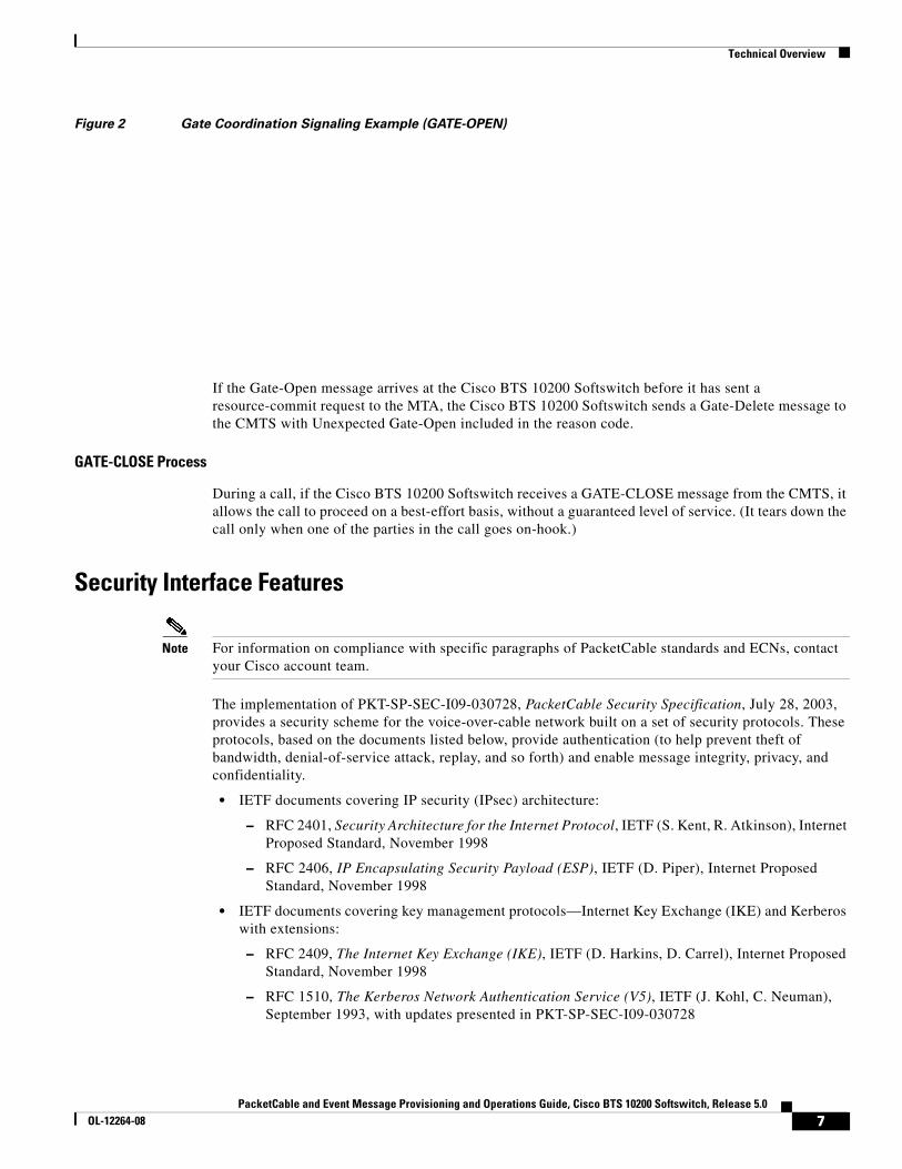
The normal coordination process for GATE-OPEN signaling, illustrated in Figure 2, has four main steps:
1. During call setup, the Cisco BTS 10200 Softswitch requests the MTA to commit bearer-path resources.
2. The MTA sends a commit message to the CMTS to request opening of the gate on the bearer path.
3. The CMTS opens the gate and sends a GATE-OPEN message to the Cisco BTS 10200 Softswitch.
4. The Cisco BTS 10200 Softswitch allows the call.
6PacketCable and Event Message Provisioning and Operations Guide, Cisco BTS 10200 Softswitch, Release 5.0
OL-12264-08
Technical Overview
Figure 2 Gate Coordination Signaling Example (GATE-OPEN)
If the Gate-Open message arrives at the Cisco BTS 10200 Softswitch before it has sent a resource-commit request to the MTA, the Cisco BTS 10200 Softswitch sends a Gate-Delete message to the CMTS with Unexpected Gate-Open included in the reason code.
GATE-CLOSE Process
During a call, if the Cisco BTS 10200 Softswitch receives a GATE-CLOSE message from the CMTS, it allows the call to proceed on a best-effort basis, without a guaranteed level of service. (It tears down the call only when one of the parties in the call goes on-hook.)
Security Interface Features
Note For information on compliance with specific paragraphs of PacketCable standards and ECNs, contact your Cisco account team.
The implementation of PKT-SP-SEC-I09-030728, PacketCable Security Specification, July 28, 2003, provides a security scheme for the voice-over-cable network built on a set of security protocols. These protocols, based on the documents listed below, provide authentication (to help prevent theft of bandwidth, denial-of-service attack, replay, and so forth) and enable message integrity, privacy, and confidentiality.
• IETF documents covering IP security (IPsec) architecture:
– RFC 2401, Security Architecture for the Internet Protocol, IETF (S. Kent, R. Atkinson), Internet Proposed Standard, November 1998
– RFC 2406, IP Encapsulating Security Payload (ESP), IETF (D. Piper), Internet Proposed Standard, November 1998
• IETF documents covering key management protocols—Internet Key Exchange (IKE) and Kerberos with extensions:
– RFC 2409, The Internet Key Exchange (IKE), IETF (D. Harkins, D. Carrel), Internet Proposed Standard, November 1998
– RFC 1510, The Kerberos Network Authentication Service (V5), IETF (J. Kohl, C. Neuman), September 1993, with updates presented in PKT-SP-SEC-I09-030728
7PacketCable and Event Message Provisioning and Operations Guide, Cisco BTS 10200 Softswitch, Release 5.0
OL-12264-08

Technical Overview
The Cisco BTS 10200 Softswitch performs the security functions of a CMS and a MGC in the PacketCable environment. It supports security in accordance with PKT-SP-SEC-I09-030728 for both signaling and media:
• Signaling security—For signaling from CMS to eMTA, CMS to CMTS, and MGC to TGW
• Media (bearer) security—For signaling between originating eMTA and terminating eMTA, which is facilitated by the CMS during call signaling setup
The system supports IPsec features for encryption and authentication on specific PacketCable-based interfaces (see Figure 1). There are two aspects to the security features, the security protocol itself (IPsec), and the key management (Kerberos or IKE). The following list summarizes the supported security type for each of the links:
• CMS to MTA (NCS)—IPsec/Kerberos
• CMS to CMTS (COPS)—IPsec/IKE
• CMS to RKS (EM over RADIUS)—IPsec/IKE
• MGC to RKS (EM over RADIUS)—IPsec/IKE
• CMS to CALEA (EM over RADIUS)—IPsec/IKE
• MGC to TGW (TGCP)—IPsec/IKE
As shown in Figure 1, there is no interface between the KDC and the Cisco BTS 10200 Softswitch. To ensure secure NCS signaling, a dynamic key exchange is performed. This exchange provides for IPsec security operations between the MTA and the Cisco BTS 10200 Softswitch. (These procedures are described in the CableLabs document PacketCable Security Specification, PKT-SP-SEC-I09-030728, under “Kerberized IPsec” and other sections.)
• Manual key provisioning must be used to match data stored in the KDC with data stored in the Cisco BTS 10200 Softswitch (pre-setup).
• The MTA must contact the KDC to obtain the credentials to talk to the server, which is in this case the Cisco BTS 10200 Softswitch.
Note For information on compliance with specific paragraphs of PacketCable standards and ECNs, contact your Cisco account team.
Note See the “Installation” section on page 15 regarding the requirement for setting the IPSEC_ENABLED parameter at the time of Cisco BTS 10200 Softswitch software installation.
Event Message FeatureThis section describes Cisco BTS 10200 Softswitch support for the EM feature.
Billing Data Options
The Cisco BTS 10200 Softswitch can provision billing support using either of the following billing data generation methods:
• Call detail blocks (CDBs)—This is traditional post-call billing data, which is assembled into call detail records (CDRs) by an external billing mediation system or billing server.
8PacketCable and Event Message Provisioning and Operations Guide, Cisco BTS 10200 Softswitch, Release 5.0
OL-12264-08
Technical Overview
• PacketCable event messages (EMs)—This is real-time call data flow, which is transferred to an external Record Keeping Server (RKS) that assembles CDRs from the EMs.
The Cisco BTS 10200 Softswitch should be provisioned to generate either EMs or CDBs, but not both.
Caution We strongly recommend that you provision the Cisco BTS 10200 Softswitch to generate either EMs or CDBs, but not both. Attempting to generate both types of records simultaneously can significantly degrade system performance. See the “Provisioning the System to Generate EMs for Billing” section on page 51 for provisioning details.
The content of the CDBs is outside the scope of this document. See the Cisco BTS 10200 Softswitch Billing Interface Guide for information about CDBs.
Description of the Event Message Feature
EMs are real-time data records containing information about network usage and activities. (They must not be confused with system event messages that report events and sometimes trigger alarms.) EMs are used in PacketCable networks to collect resource usage data for billing purposes. In the PacketCable architecture, EM generation is based on the half-call model. A single EM can contain complete usage data or it might contain only part of the usage information.
The Record Keeping Server (RKS) is a PacketCable network element that receives EMs from network elements, such as the call management server (CMS), media gateway controller (MGC), and the cable modem termination system (CMTS). The physical Cisco BTS 10200 Softswitch contains both CMS and MGC logical network elements. The EMs generated by both the CMS and MGC are sent to the RKS. The RKS correlates the information in multiple EMs and provides the complete record of service for a call, which is referred to as a CDR.
For information about EM-related operations on the Cisco BTS 10200 Softswitch, see the “Operations, Billing, and EM Transfer Procedures” section on page 56.
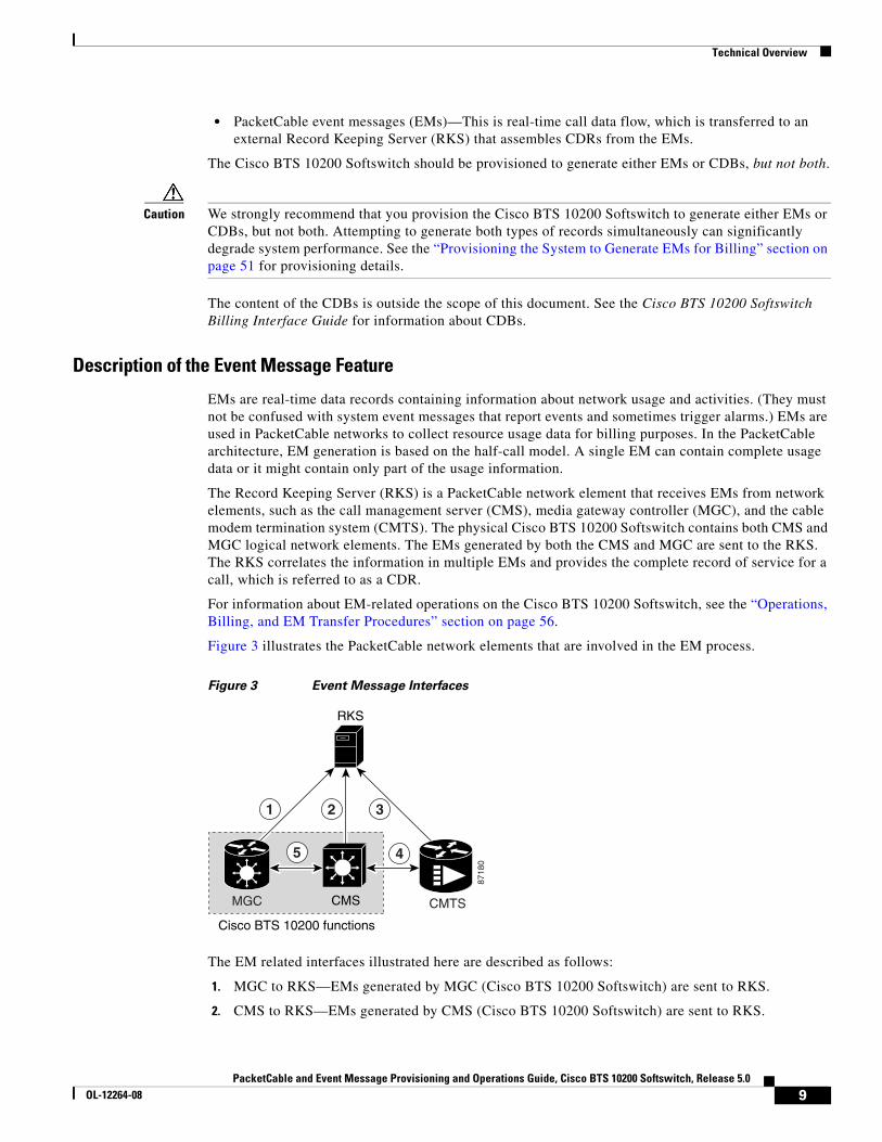
Figure 3 illustrates the PacketCable network elements that are involved in the EM process.
Figure 3 Event Message Interfaces
The EM related interfaces illustrated here are described as follows:
1. MGC to RKS—EMs generated by MGC (Cisco BTS 10200 Softswitch) are sent to RKS.
2. CMS to RKS—EMs generated by CMS (Cisco BTS 10200 Softswitch) are sent to RKS.
8718
0
1 32
45
Cisco BTS 10200 functions
CMTS
RKS
CMSMGC
9PacketCable and Event Message Provisioning and Operations Guide, Cisco BTS 10200 Softswitch, Release 5.0
OL-12264-08

Technical Overview
3. CMTS to RKS—EMs generated by CMTS are sent to RKS. The Cisco BTS 10200 Softswitch (MGC/CMS) is not involved.
4. CMS to CMTS—CMS (Cisco BTS 10200 Softswitch) sends the billing correlation ID (BCID) to the CMTS using the DQoS GateSet message.
5. CMS to MGC—An internal exchange of originating/terminating information such as BCID and FEID.
PacketCable EMs can support billing and settlement activities for single-zone architectures. The originating and terminating CMSs exchange unique Billing Correlation IDs (BCIDs) and Financial Entity IDs (FEIDs) for each half of the call. The originating CMS sends a BCID and an FEID in the INVITE message. The Cisco BTS 10200 Softswitch allocates the BCID for calls it originates or terminates. Along with the FEID, the BCID is used across network elements to reference calls. The FEID is provisioned on a system-wide basis (a single setting for the Cisco BTS 10200 Softswitch) as defined in the “Provisioning the System to Generate EMs for Billing” section on page 51.
Event Message Generation Details and Content
See the “EM Generation Details and Content” section on page 66 for information on EM data.
Timestamp Support for Event Messages
The system-generated timestamps for EMs are based on the host operating system (OS) time and time zone. This data is not affected by CLI provisioning. The Solaris OS obtains the time automatically through Network Time Protocol (NTP) services.
Caution You should never attempt to modify the system date or time in a Cisco BTS 10200 Softswitch host machine while system components (CA, FS, EMS, and BDMS) are running. The attempt could cause the system to have serious problems. Allow the Solaris OS to obtain the time automatically through NTP services.
Event Message Transport
Remote Access Dial-In User Service (RADIUS) is a client/server protocol used for Authorization, Authentication, and Accounting (AAA). The RADIUS protocol is an industry standard for remote access AAA defined in a set of Internet Engineering Task Force (IETF) standards: RFC 2865 and RFC 2866.
The RADIUS transport protocol is used between the Cisco BTS 10200 Softswitch (CMS/MGC) and the RKS. The RKS (or mediation device) communicates with the IP port configured in platform.cfg file for event message adapter (EMA) process (responsible for sending RADIUS message to the network) in BTS 10200.
Note You should not have both the signaling and management interfaces available to the billing mediation center (the remote end of the RADIUS link). EM packets can originate on any of the BTS 10200 interfaces. Only those EM packets originating in the management network should be allowed. Ensure that the client side can account for the temporary receipt of packets from the two management interfaces of the BTS 10200.
The system sends EMs to an RKS without waiting for acknowledgment of the previous message. The maximum number of pending ACK messages is 256.
10PacketCable and Event Message Provisioning and Operations Guide, Cisco BTS 10200 Softswitch, Release 5.0
OL-12264-08
Technical Overview
EMs are first sent to the primary RKS. If the specified number of retry attempts fail, the EMs are sent to the secondary RKS. If one RKS is found to be unreachable, then the other RKS is considered for subsequent messages. If both the primary and secondary RKSs become unreachable, the EMs are stored in an error file on the hard disk (as described in the “Event Message Storage on the CA” section on page 11) and a timer is started. When the timer expires, newly arriving EMs are sent to the primary RKS.
If EMs are being sent to the primary RKS and the primary RKS goes down, the Cisco BTS 10200 Softswitch sends subsequent EMs to the secondary RKS. When the primary RKS comes back up, the Cisco BTS 10200 Softswitch continues to send EMs to the secondary RKS. (It does not automatically begin sending them to the primary RKS.) Provisioning of timers and retry attempts is described in the “Provisioning Support for EM Transmission and Storage” section on page 48.
Event Message Storage on the CA
Note For information on compliance with specific paragraphs of PacketCable standards and ECNs listed in this document, contact your Cisco account team.
EMs are stored in the network element (CA) that generates them until they are transferred to the RKS. After receipt of the EMs is acknowledged by the RKS, they are deleted. The number of EMs generated by the Cisco BTS 10200 Softswitch depends on the number of calls processed. Multiple EMs are generated for each call. Depending on provisioning in the call-agent-profile table and the type of call, EMs can be generated by the CMS or MGC (or both) within the CA. The exact storage requirement varies depending on the rate of EM generation and how long the Cisco BTS 10200 Softswitch is required to keep the records before transferring them to an RKS.
The Cisco BTS 10200 Softswitch generates and stores EMs with the following characteristics:
• EMs are generated in real time during a call. EMs contain timestamps with a granularity of 1 millisecond. The time interval between generation and transmission is not specified.
• The Cisco BTS 10200 Softswitch synchronizes with the network clock using NTP at least once per hour. The deviation of the clock in the Cisco BTS 10200 Softswitch remains within ±100 milliseconds between NTP synchronizations.
• EMs that cannot be successfully transferred to the RKS due to loss of communication are stored in the /opt/BTSem directory on the CA. The system uses the file-naming conventions specified in PacketCable ECN EM-N-04.0186-3 for the stored EMs. The maximum EM file size and the time limit on keeping a file open are provisionable, as described in the “Provisioning Support for EM Transmission and Storage” section on page 48. These files are not automatically deleted or transferred out of the CA.
Caution Event messages that cannot be successfully transferred to the RKS due to loss of communication are not automatically deleted or transferred out of the CA. You must transfer these files to the RKS when communication is restored.
The procedure for doing this is provided in the “Manual Recovery and Transfer of Stored EMs” section on page 58.
• Each time an EM file is placed in local storage, the system checks current disk usage and takes the following actions:
– The system generates an alarm if the disk space allocated to EMs fills up to a certain level—50 percent (minor alarm), 70 percent (major alarm), or 100 percent (critical alarm).
11PacketCable and Event Message Provisioning and Operations Guide, Cisco BTS 10200 Softswitch, Release 5.0
OL-12264-08

Technical Overview
– When the critical condition is reached, the system issues a critical alarm, and further EMs are dropped without any additional warning.
– When the critical condition is reached, the disk usage is monitored periodically (one time every minute) to check if disk space usage has decreased and EMs can be stored again.
PCMM-Based QoS for Type 1 ClientsThis section describes the implementation of the PacketCable Multimedia (PCMM) feature that provides quality of service (QoS) for type 1 clients managed by the Cisco BTS 10200 Softswitch. This feature is applicable to endpoints using SIP, MGCP, or H.323 as the call signaling protocol.
Note The Cisco BTS 10200 Softswitch supports this PCMM-based feature in addition to all of the PacketCable-based features provided in earlier releases. If you would like detailed information on compliance with specific PacketCable specifications, contact your Cisco account team.
Figure 4 provides a sample system context for this feature.
Figure 4 Network Architecture with Policy Server and PCMM Interfaces
As shown in Figure 4, the PCMM implementation requires the Cisco BTS 10200 Softswitch to communicate with a policy server (PS), which is a third party device. For calls originating on, or terminating to a type 1 client, the Cisco BTS 10200 Softswitch acts as an application manager (AM) and sends requests to the PS for admission control through PCMM-based signaling. The PS in turn requests the CMTS to allocate bandwidth and other resources as in the request. After resources are allocated, the results are provided to the AM (via the PS) and the Cisco BTS 10200 Softswitch continues with call signaling to set up the call.
For the CLI provisioning procedure related to PCMM-based functions, see the “Provisioning PCMM-Based QoS for Type 1 Clients” section on page 53.
1913
60
Cisco BTS 10200 Softswitch(application manager)
ModemIP
PCMM/COPSPolicyserver
DQoS/COPS
CMTS
DOCSIS
Fiber optictransmitter
SIP/H.323/MGCP
Type-1 deviceSIP/H.323/MGCP
PCMM/COPS
12PacketCable and Event Message Provisioning and Operations Guide, Cisco BTS 10200 Softswitch, Release 5.0
OL-12264-08

Technical Overview
For maintenance commands related to the CMTS and PS, see the “Reset, Control, and Status Commands” section on page 57.
SOAP/XML Interface for CMS Subscriber ProvisioningThis section describes the implementation of PacketCable CMS subscriber provisioning on the BTS 10200 with a Simple Object Access Protocol/Extensible Markup Language (SOAP/XML) interface.
This initial release supports only the Pkt-p1 interface to the Provisioning Server (PS)/Call Management Server (CMS) and only the PcspService Object, without extensions. It supports a subset of the call feature objects in the ListOfCallFeatures element.
In the Pkt-p1 interface, the Cisco BTS 10200 Softswitch plays the role of CMS. Any third-party PS using SOAP, Version 1.1, can provision the BTS. The requests and responses between the CMS and the PS are encapsulated in SOAP, Version 1.1, messages. A secure transport protocol is provided by Internet Protocol Security (IPSec).
SOAP/XML Interface
Currently, a user can connect to a BTS 10200 Common Object Request Broker Architecture (CORBA) server to access command templates and enter command executions, allowing system-to-system provisioning. The feature described in this document allows the XML commands to be transported by the SOAP transport protocol, rather than CORBA. Users of this feature communicate with a BTS SOAP server, which resides on the BTS 10200 EMS.
The BTS 10200 XML schema is a general purpose schema currently used by the XML/CORBA interface. The XML schema does not change with the incorporation of the SOAP transport protocol.
SOAP/XML Adapter and specifications are documented in the Cisco BTS10200 Softswitch SOAP Adapter Interface Specification Programmer Guide.
System Components
CMS subscriber provisioning involves the interface between the following components:
• Provisioning Server (PS)—Provides the interface between the service provider’s back office components and the PacketCable elements. The PS consists of a provisioning application that contains provisioning logic and a provisioning SNMP entity that provides access to active components.
• Call Management Server (CMS)—Provides call control and signaling-related services for the MTA and CMTS in the PacketCable network. The BTS 10200 is the CMS.
CMS Subscriber Provisioning
CMS subscriber provisioning includes the operations necessary to provide a specified service to a customer and provides two main functions:
• CMS Basic POTS Provisioning (BPP)—Provides the CMS with the minimum information necessary for routing of plain old telephone service (POTS) in the PacketCable network. Data consists of a telephone number mapped to its associated MTA’s FQDN and NCS endpoint identifier and is used to set up translation tables enabling the CMS to route calls to the appropriate device given a specific telephone number. BPP for a customer is required before the customer can receive any calls.
13PacketCable and Event Message Provisioning and Operations Guide, Cisco BTS 10200 Softswitch, Release 5.0
OL-12264-08

Technical Overview
• CMS Call Feature Provisioning (CFP)—Provides call features to a customer.
Call Features
The following call features are supported by the PacketCable CMS subscriber provisioning interface. The name of each feature is listed below in PacketCable terminology, followed by the corresponding BTS 10200 feature in ( ):
• Calling Number Delivery (CND)
• Calling Name Delivery (CNAM)
• Calling Identity Delivery on Call Waiting (CIDCW)
• Call Waiting (CW)
• Cancel Call Waiting (CCW)
• Call Forwarding Variable and Usage-Sensitive Call Forwarding (*72/*73) (CFVBBG)
• Automatic Recall (*69) (AR)
• Automatic Callback (*66) (AC)
• Visual Message Waiting Indicator (VMWI)
• Customer Originated Trace (*57) (COT)
• Three Way Calling/Usage-Sensitive Three-Way Calling (*71) (TWC)
• Remote Activation of Call Forwarding (RACF)
• Anonymous Call Rejection (*77/*87) (ACR)
• Call Forwarding Busy Line (*68/*40/*88) (CFB)
• Call Forwarding Don’t Answer (*68/*24/*88) (CFNA)
• Call Forwarding Combination (CFU)
• Selective Call Forwarding (*63/*83) (SCF)
• Selective Call Acceptance (*64/*84) (SCA)
• Selective Call Rejection (*60/*80) (SCR)
• Distinctive Ringing/Call Waiting (*61/*81) (DRCW)
• Speed Calling (*74/*75) (SC1D)
• Line Service Restriction (COS)
• Do Not Disturb (DND)
Prerequisites for CMS Subscriber Provisioning
• The web server and SOAP engine are running
• The CMS and the PS reside in the same secure provisioning domain
Limitations On CMS Subscriber Provisioning
• The CMS provisioning interface is limited to the exchange of service activation data between the CMS and the provisioning server.
14PacketCable and Event Message Provisioning and Operations Guide, Cisco BTS 10200 Softswitch, Release 5.0
OL-12264-08

Planning
• The CMS provisioning interface supports only the existing CMS subscriber provisioning functionality in the BTS 10200.
• The scope of the feature is limited to subscriber provisioning in a PacketCable 1.5 network
• The system supports only the Pkt-p1 interface to the provisioning server/CMS and only the PcspService Object, without extensions. It supports a subset of the call feature objects in the ListOfCallFeatures element.
PlanningDelivery of the features and functions described in this document requires interoperability with the network elements connected to the Cisco BTS 10200 Softswitch. See the “Component Interoperability” section in the Cisco BTS 10200 Softswitch Release Notes, which lists the specific peripheral platforms, functions, and software loads that have been tested by Cisco for interoperability with the Cisco BTS 10200 Softswitch.
Note The “Component Interoperability” section in the Cisco BTS 10200 Softswitch Release Notes is intended as a guide. Earlier or later releases of platform software might be interoperable, and it might be possible to use other functions on these platforms. The list certifies only that the required interoperation of these platforms, the functions listed, and the protocols listed have been successfully tested with the Cisco BTS 10200 Softswitch.
InstallationInstallation of Cisco BTS 10200 Softswitch software follows a standard process. For details, see the Application Installation Procedure in the Cisco BTS 10200 Softswitch documentation set. Of the three main PacketCable feature areas (DQoS, EM, and security), two of them (DQoS and EM) are always installed, and do not require the setting of any special flags during software installation. However, the third area (security) is not installed unless a special flag (IPSEC_ENABLED) is set in the opticall.cfg file during software installation.
Caution We strongly recommend that you contact Cisco TAC if you believe that you might need to reinstall Cisco BTS 10200 Softswitch software in order to change the value of IPSEC_ENABLED.
Provisioning ProceduresThis section explains how to perform the following procedures:
• Provisioning Basic PacketCable and DQoS Features, page 16
• Provisioning Security Interfaces, page 39
• Provisioning Event Messages, page 48
• Provisioning PCMM-Based QoS for Type 1 Clients, page 53
• Provisioning AuditConnection Parameters, page 55
15PacketCable and Event Message Provisioning and Operations Guide, Cisco BTS 10200 Softswitch, Release 5.0
OL-12264-08

Provisioning Procedures
These tasks include examples of CLI commands that illustrate how to provision the specific feature. Most of these tables have additional tokens that are not included in the examples. For a complete list of all CLI tables, tokens, descriptions, valid ranges, and default values, see the Cisco BTS 10200 Softswitch Command Line Interface Reference Guide.
Note The command sequences shown in this section provide guidance on how to provision a new system. Therefore, in most cases the commands are “add” commands. If you are modifying previously provisioned GWs, TGs, and so forth, use the “change” commands.
Provisioning Basic PacketCable and DQoS FeaturesThis section describes how to provision the Cisco BTS 10200 Softswitch interfaces to connect to other PacketCable-based NEs and how to select dynamic quality of service (DQoS) options. It includes the following tasks:
• Provisioning CMS Parameters, page 16
• Provisioning the CMS Interfaces to the CMTS and eMTA, page 18
• Provisioning DQoS Parameters for Codec Negotiation Service, page 21
• Provisioning TGCP Interfaces to TGWs, page 22
• Provisioning the Keepalive AUEP and ICMP Ping Options, page 24
• Provisioning MGCP Command Timeout and QoS Parameters, page 25
• Provisioning the Aggregation ID Subnet, page 27
Provisioning CMS Parameters
This section describes how to provision DQoS functionality for the CMS logical entity on the Cisco BTS 10200 Softswitch (Call Agent).
SUMMARY STEPS
1. Enable DQoS support—change call-agent-profile.
2. Set CMS timers in Call Agent Configuration (ca-config) table (optional, if using other than the default values)—change ca-config.
3. Set the local ringback flag, differential service code point (DSCP)/type of service (TOS) parameter, and maximum MGCP datagram sizes in the ca-config table (optional, if using other than the default values)—change ca-config.
Note The token values shown in this section are examples.
16PacketCable and Event Message Provisioning and Operations Guide, Cisco BTS 10200 Softswitch, Release 5.0
OL-12264-08

Provisioning Procedures
DETAILED STEPS
Command Examples Purpose
Step 1 change call-agent-profile id=CA146; dqos-supp=y; description=BostonCA33
Enables DQoS support.
The command is shown as change call-agent-profile. However, if the system responds that the call-agent-profile ID does not exist, reenter the command as add call-agent-profile.
Step 2 change ca-config type=DQOS-T1-TIMER;datatype=INTEGER; value=250;
change ca-config type=DQOS-DS-SLACK-TERM;datatype=INTEGER; value=30000;
change ca-config type=DQOS-GATE-TIMER;datatype=INTEGER; value=3;
Specifies values other than the defaults for individual CMS timers in the ca-config table. The applicable timers are DQOS-T1-TIMER, DQOS-T5-TIMER, DQOS-T7-TIMER, DQOS-T8-TIMER, DQOS-DS-SLACK-TERM, DQOS-US-SLACK-TERM, and DQOS-GATE-TIMER.
The default values for these timers might be adequate for your specific case. In each case, you can use the show command to find out how the parameter is currently set. See the Cisco BTS 10200 Softswitch Command Line Interface Reference Guide for parameter definitions and valid ranges.
The command is shown as change ca-config. However, if the system responds that the parameter does not exist, reenter the command as add ca-config.
17PacketCable and Event Message Provisioning and Operations Guide, Cisco BTS 10200 Softswitch, Release 5.0
OL-12264-08

Provisioning Procedures
Provisioning the CMS Interfaces to the CMTS and eMTA
This section describes how to provision the interfaces to the CMTS and eMTA nodes. Specific tables are provisioned for each of these interfaces:
• CMTS—The Aggregation Profile (aggr-profile) and Aggregation (aggr) tables define the parameters for the connected CMTS devices. These parameters are used by the COPS adapter to establish and terminate TCP connections to the CMTS.
• MTA (or eMTA)—The Cisco BTS 10200 Softswitch uses the Media Gateway Profile (mgw-profile), mgw, and termination tables to establish and terminate connections to the eMTAs. The supported MGCP variant is NCS. The following tables are provisioned for this interface:
– The mgw-profile table provides templates for defining each type of eMTA by hardware vendor. It identifies the specifications and settings necessary for communications between the Cisco BTS 10200 Softswitch (which functions as the CMS) and each type of eMTA. An mgw-profile ID must be created in this table before entries can be added to the mgw table. Several tokens have values that can be overwritten after the Cisco BTS 10200 Softswitch (CMS) queries the eMTA for supported capabilities. If the eMTA returns a value different from the value originally provisioned in the Cisco BTS 10200 Softswitch, the returned value automatically replaces the originally provisioned value.
Step 3 change ca-config type=LOCAL-RINGBACK;datatype=BOOLEAN; value=N;
change ca-config type=COPS-DSCP-TOS;datatype=INTEGER; value=96;
change ca-config type=MAX-MGCP-DATAGRAM;datatype=INTEGER; value=3900;
Specifies additional ca-config parameters that can be set to values other than the defaults.
The default values for these parameters might be adequate for your specific case. In each case, you can use the show command to find out how the parameter is currently set. See the Cisco BTS 10200 Softswitch Command Line Interface Reference Guide for parameter definitions and valid ranges.
Caution We do not recommend that you change the DSCP value unless necessary, and recommend that you contact Cisco TAC regarding any plans to change it.
The MAX-MGCP-DATAGRAM parameter specifies the maximum size of an MGCP message datagram (which can include one or more piggybacked messages) that the Cisco BTS 10200 Softswitch can decode before discarding the rest of the message part. The default value of 4000 bytes is adequate for most applications, and Cisco does not recommend that you change this value unless you are deploying MGCP-based media gateways or MTAs that require larger datagram sizes.
The command is shown as change ca-config. However, if the system responds that the parameter does not exist, reenter the command as add ca-config.
Command Examples Purpose
18PacketCable and Event Message Provisioning and Operations Guide, Cisco BTS 10200 Softswitch, Release 5.0
OL-12264-08

Provisioning Procedures
– The mgw table holds information about each eMTA managed by the Cisco BTS 10200 Softswitch (CMS). The eMTA can be uniquely addressed by domain name, an IP address, or the TSAP address.
– The termination table holds information about each endpoint in eMTAs managed by the CMS. Termination events and signals are grouped into packages, which are groupings of events and signals supported by a particular type of endpoint, such as an eMTA endpoint. One or more packages can exist for a given endpoint-type.
SUMMARY STEPS
1. Create the CMTS and enable DQoS support—add aggr-profile and add aggr.
2. Create the profile for eMTA and specify the appropriate parameters—add mgw-profile.
3. Verify that all parameters affecting eMTAs are properly populated, either by default or by the operator—show mgw-profile.
4. Modify parameters affecting eMTAs, if necessary—change mgw-profile.
5. Create the specific eMTA, associate it with the applicable CMTS, and set appropriate parameters—add mgw.
6. Add the line termination for an eMTA—add termination.
7. Bring the eMTA into service—control mgw.
8. Equip the termination and place it in service— equip subscriber-termination and control subscriber-termination.
Note The token values shown in this section are examples.
19PacketCable and Event Message Provisioning and Operations Guide, Cisco BTS 10200 Softswitch, Release 5.0
OL-12264-08

Provisioning Procedures
DETAILED STEPS
Command Examples Purpose
Step 1 add aggr-profile id=aggrprofile001; dqos-supp=y;
add aggr id=cmts777;tsap-addr=ADDRESS123.cisco.com; aggr-profile-id=aggrprofile001
Creates the CMTS (aggregation device) and enables DQoS support.
The TSAP-ADDR can be a DNS or IP address. If you enter a DNS address, it must be a fully qualified domain name (FQDN).
Caution DQoS is disabled (DQOS-SUPP=N) by default. Set this value to Y to enable DQoS.
Step 2 add mgw-profile id=mgwprofile777; mgcp-version=MGCP-1-0; mgcp-variant=NCS-1-0; mgcp-default-pkg=LINE; mgcp-conn-id-at-gw-supp=n;
Creates the mgw-profile for this type of eMTA, and specifies values for the optional parameters.
The default values for these parameters might be adequate for your specific case. In each case, you can use the show command to find out how the parameter is currently set. See the Cisco BTS 10200 Softswitch Command Line Interface Reference Guide for parameter definitions and valid ranges.
Step 3 show mgw-profile id=mgwprofile777;
Verify that the following values are present:
vendor=Cisco [or applicable vendor name]
mgcp-version=MGCP-1-0
mgcp-variant=NCS-1-0
mgcp-default-pkg=LINE
codec-neg-supp=y
pc-mptime-supp=y
mgcp-xdlcx-supp=n
domain-name-caching-supp=y
mgcp-conn-id-at-gw-supp=y
Shows the provisioned values for the parameters in the mgw-profile table.
Step 4 change mgw-profile id=mgwprofile777; mgcp-version=MGCP-1-0; mgcp-variant=NCS-1-0;
If any of the mgw-profile token values (from Step 3) need to be changed, use the change mgw-profile command.
Step 5 add mgw id=CiscoGW50; tsap-addr=192.168.26.104; call-agent-id=CA146; mgw-profile-id=mgwprofile777; type=rgw; aggr-id=cmts777; node=main0044;
Creates the MGW ID for a single eMTA, and specifies values for the other required parameters.
Be sure to set TYPE=RGW for an eMTA.
You must enter the value for AGGR-ID to identify the appropriate CMTS for this eMTA.
The node token allows you to identify a hybrid fiber coax (HFC) node to which the eMTA is assigned. Typically, each eMTA is assigned to a node, and one or more nodes are assigned to a CMTS.
20PacketCable and Event Message Provisioning and Operations Guide, Cisco BTS 10200 Softswitch, Release 5.0
OL-12264-08

Provisioning Procedures
Provisioning DQoS Parameters for Codec Negotiation Service
The Quality of Service (qos) table is used in providing the codec negotiation service. Codec negotiation is the process the Cisco BTS 10200 Softswitch uses to find a common codec for the compression or decompression of a signal between two gateways. The Subscriber Profile (subscriber-profile) and Subscriber (subscriber) tables point to the qos table.
The following commands allow you to specify the required characteristics for these tables.
SUMMARY STEPS
1. Provision QOS parameters—add qos.
2. Assign a specific QOS to each subscriber-profile or subscriber—add subscriber-profile; add subscriber.
Note The token values shown in this section are examples.
Step 6 add termination prefix=aaln/; port-start=1; port-end=2; type=LINE; mgw-id=CiscoGW50;
Creates the line termination for the eMTA and specifies values for the required parameters.
For eMTA terminations, always enter type=LINE.
Step 7 control mgw id=CiscoGW50; target-state=INS; mode=forced;
status mgw id=CiscoGW50;
Brings the eMTA in service (INS state), and verifies that the administrative state is INS.
Step 8 equip subscriber-termination id=sub3456;
control subscriber-termination id=sub3456; target-state=INS; mode=forced;
status subscriber-termination id=sub3456;
Equips the termination, places it in service (INS state), and verifies that the administrative state is INS.
Command Examples Purpose
21PacketCable and Event Message Provisioning and Operations Guide, Cisco BTS 10200 Softswitch, Release 5.0
OL-12264-08

Provisioning Procedures
DETAILED STEPS
Provisioning TGCP Interfaces to TGWs
This section describes how to provision the TGCP interfaces to the TGWs.
The mgw-profile table provides templates for defining each type of TGW by hardware vendor. It identifies the specifications and settings necessary for communications between the Cisco BTS 10200 Softswitch (which functions as the MGC) and each type of TGW. Several tokens in this table have values that can be overwritten after the Cisco BTS 10200 Softswitch (MGC) queries the TGW for supported capabilities. If the TGW returns a value different from the value originally provisioned in the Cisco BTS 10200 Softswitch, the returned value automatically replaces the originally provisioned value.
SUMMARY STEPS
1. Enable TGCP support for each type of TGW—add mgw-profile.
2. Link each TGW to an mgw-profile—add mgw.
3. Add the trunk termination for a TGW—add termination.
4. Provision QOS parameters—add qos.
5. Assign a QOS-ID to the TGW—add trunk-grp.
Note The token values shown in this section are examples.
Command Examples Purpose
Step 1 add qos id=Gold1; codec-type=PCMU; client-type=dqos;
Adds a qos with the preferred codec type, specifies client type as DQoS, and other parameters as needed.
You must enter client-type=dqos in this command (and then assign this qos ID to the subscriber or subscriber-profile in the next step) to enable DQoS functionality for the subscriber.
Step 2 add subscriber-profile id=richardson; dial-plan-id=dp1; POP=BLDG222; qos-id=Gold1;
add subscriber id=Person29; dn1=800-555-0029; sub-profile-id=richardson; term-type=none;
add subscriber id=Person123; dn1=800-555-0123;sub-profile-id=richardson; qos-id=Gold1; term-type=none;
Assigns a qos ID to each subscriber-profile and/or subscriber.
You must assign the qos ID (the ID of the qos table that was provisioned in the previous step) to the subscriber or subscriber-profile to enable DQoS functionality for the subscriber.
22PacketCable and Event Message Provisioning and Operations Guide, Cisco BTS 10200 Softswitch, Release 5.0
OL-12264-08

Provisioning Procedures
DETAILED STEPS
Command Examples Purpose
Step 1 add mgw-profile id=tgwprf222; vendor=cisco; mgw-type=MGX8850; mgcp-version=MGCP-1-0; mgcp-variant=TGCP-1-0; mgcp-default-pkg=TRUNK; pc-mptime-supp=y;
Creates an mgw-profile for this type of TGW and specifies values for required parameters.
Be sure to set the following values for a TGW:MGCP-VERSION=MGCP-1-0MGCP-VARIANT=TGCP-1-0MGCP-DEFAULT-PKG=TRUNK
Note For most TGWs, set PC-MPTIME-SUPP to Y. However, for a Cisco MGX8850 VISM gateway, the MP function is not available. Therefore, set the PC-MPTIME-SUPP token to N for a Cisco MGX8850 VISM gateway.
Step 2 add mgw id=tgw50; tsap-addr=TGW1515.cisco.com; call-agent-id=CA146; mgw-profile-id=tgwprf222; type=tgw;
Links a specific TGW to the applicable mgw-profile.
Note Be sure to set TYPE=TGW.
Step 3 add termination prefix=S0/ds1-2/; mgw-id=tgw50; port-start=1; port-end=24; type=TRUNK;
Creates trunk terminations for the TGW.
Note Be sure to set TYPE=TRUNK.
Step 4 add qos id=gold-service; lptime=20; hptime=20; codec-type=PCMU; client-type=dqos;
Adds a qos with the preferred codec type, specifies client type as DQoS, and other parameters as needed.
You must enter client-type=dqos in this command (and then assign this qos ID to the trunk-grp in the next step) to enable DQoS functionality for the trunk group.
Caution Provision the same values for lptime and hptime for both MGWs in the call. See the explanation in the qos table in the Cisco BTS 10200 Softswitch Command Line Reference Guide.
Step 5 add trunk-grp id=101; call-agent-id=CA146; tg-type=ss7; qos-id=gold-service; mgcp-pkg-type=IT; pop-id=chicago333;
Assigns a qos ID and pop ID to each TRUNK-GRP.
For trunk groups on TGCP-based TGWs (MGCP-VARIANT=TGCP-1-0 in the mgw-profile table), set the MGCP-PKG-TYPE value to IT (ISUP trunk package).
You must assign the qos ID (the ID of the qos table that was provisioned in the previous step) to the trunk-grp to enable DQoS functionality for the trunk group.
23PacketCable and Event Message Provisioning and Operations Guide, Cisco BTS 10200 Softswitch, Release 5.0
OL-12264-08

Provisioning Procedures
Provisioning the Keepalive AUEP and ICMP Ping Options
This section explains how to provision the keepalive AUEP and ICMP ping options. There are two tokens to provision:
• AUEP and ICMP pings can be globally disabled on the system by use of the mgw-monitoring-enabled token in the Call Agent (call-agent) table.
• If globally enabled in the call-agent table, these pings can be selectively enabled or disabled for each mgw-profile by use of the keepalive-method token in the mgw-profile table. Each MGW (eMTA) is linked to an mgw-profile by means of the mgw table.
SUMMARY STEPS
1. Show the setting for mgw-monitoring-enabled—show call-agent.
2. If necessary, change the value of mgw-monitoring-enabled—change call-agent.
3. Show the setting for keepalive-method—show mgw-profile.
4. If necessary, change the value of keepalive-method—change mgw-profile.
5. If necessary, change the value of other keepalive tokens—change mgw-profile.
6. Link individual MGWs (eMTAs) to MGW profiles—add mgw.
Note If mgw-monitoring-enabled=Y (the default value) in the call-agent table, the system checks the provisioning of the keepalive-method token in the mgw-profile table for each MGW.
However, if mgw-monitoring-enabled=N, the AUEP and the ICMP ping are globally disabled, and the keepalive-method token is not checked.
The token values shown in this section are examples. In addition, these tables have many additional optional tokens not shown in these examples. For a complete list of all the tokens for each table, see the Cisco BTS 10200 Softswitch Command Line Interface Reference Guide.
24PacketCable and Event Message Provisioning and Operations Guide, Cisco BTS 10200 Softswitch, Release 5.0
OL-12264-08

Provisioning Procedures
DETAILED STEPS
Provisioning MGCP Command Timeout and QoS Parameters
This section describes the steps required to provision the parameters for MGCP command timeout, silence suppression, and echo cancellation.
• MGCP command message timeout is a system-wide MGCP parameter, provisioned in the Call Agent Configuration (ca-config) table.
• The QoS parameters for silence suppression and echo cancellation are provisioned in the Quality of Service (qos) table.
Command Examples Purpose
Step 1 show call-agent id=CA146;
The system responds with the current settings for the call-agent table. The default value of mgw-monitoring-enabled is Y.
Show the setting for mgw-monitoring-enabled in the call-agent table.
Step 2 change call-agent id=CA146; tsap-addr=CA146.cisco.com; mgw-monitoring-enabled=Y;
If the current value of mgw-monitoring-enabled is N, use this command to change it to Y. (Otherwise, go to Step 3.)
Step 3 show mgw-profile id=mgwprofile001;
The system responds with the current settings for the mgw-profile table.
Show the setting for keepalive-method in the mgw-profile table.
Step 4 change mgw-profile id=mgwprofile001; keepalive-method=<value (see options)>;
change mgw-profile id=mgwprofile001; keepalive-method=auep-icmp;
If necessary, change the value of keepalive-method in the mgw-profile table.
The options for keepalive-method are:
• none—Disable both AUEP and ICMP ping.
• auep—Enable AUEP ping but not ICMP ping (this is the default value).
• auep-icmp—Enable sending of an AUEP ping followed (if AUEP is unsuccessful) with an ICMP ping.
Step 5 change mgw-profile id=mgwprofile001; mgcp-keepalive-interval=120; mgcp-keepalive-retries=4; mgcp-max-keepalive-interval=720; mgcp-max1-retries=3; mgcp-max2-retries=4;
If necessary, change the value of other keepalive tokens in the mgw-profile table.
The mgcp-max1-retries and mgcp-max2-retries tokens can be adjusted, if necessary, to improve response if there are network bandwidth or reliability issues, or if an MGW is slow in responding to commands from the CA. For a detailed explanation of how these and other parameters affect the keepalive process, see Appendix C of the Cisco BTS 10200 Softswitch Troubleshooting Guide.
Step 6 add mgw id=mgw_abc; mgw-profile-id=mgwprofile001; Links an individual MGW (eMTA) to an mgw-profile.
25PacketCable and Event Message Provisioning and Operations Guide, Cisco BTS 10200 Softswitch, Release 5.0
OL-12264-08
Provisioning Procedures
Command Examples Purpose
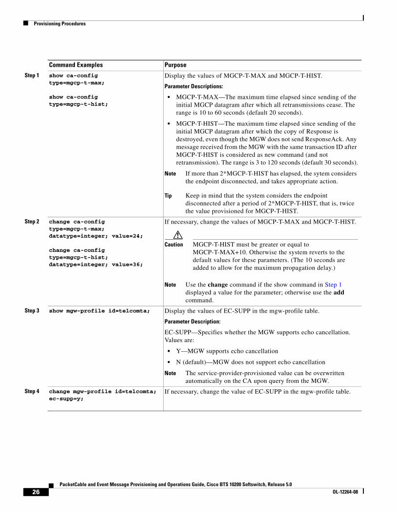
Step 1 show ca-config type=mgcp-t-max;
show ca-config type=mgcp-t-hist;
Display the values of MGCP-T-MAX and MGCP-T-HIST.
Parameter Descriptions:
• MGCP-T-MAX—The maximum time elapsed since sending of the initial MGCP datagram after which all retransmissions cease. The range is 10 to 60 seconds (default 20 seconds).
• MGCP-T-HIST—The maximum time elapsed since sending of the initial MGCP datagram after which the copy of Response is destroyed, even though the MGW does not send ResponseAck. Any message received from the MGW with the same transaction ID after MGCP-T-HIST is considered as new command (and not retransmission). The range is 3 to 120 seconds (default 30 seconds).
Note If more than 2*MGCP-T-HIST has elapsed, the sytem considers the endpoint disconnected, and takes appropriate action.
Tip Keep in mind that the system considers the endpoint disconnected after a period of 2*MGCP-T-HIST, that is, twice the value provisioned for MGCP-T-HIST.
Step 2 change ca-config type=mgcp-t-max; datatype=integer; value=24;
change ca-config type=mgcp-t-hist; datatype=integer; value=36;
If necessary, change the values of MGCP-T-MAX and MGCP-T-HIST.
Caution MGCP-T-HIST must be greater or equal to MGCP-T-MAX+10. Otherwise the system reverts to the default values for these parameters. (The 10 seconds are added to allow for the maximum propagation delay.)
Note Use the change command if the show command in Step 1 displayed a value for the parameter; otherwise use the add command.
Step 3 show mgw-profile id=telcomta; Display the values of EC-SUPP in the mgw-profile table.
Parameter Description:
EC-SUPP—Specifies whether the MGW supports echo cancellation. Values are:
• Y—MGW supports echo cancellation
• N (default)—MGW does not support echo cancellation
Note The service-provider-provisioned value can be overwritten automatically on the CA upon query from the MGW.
Step 4 change mgw-profile id=telcomta; ec-supp=y;
If necessary, change the value of EC-SUPP in the mgw-profile table.
26PacketCable and Event Message Provisioning and Operations Guide, Cisco BTS 10200 Softswitch, Release 5.0
OL-12264-08

Provisioning Procedures
Provisioning the Aggregation ID Subnet
Establishing subnets for MTAs enables a service provider to use the Subnet table to statically configure all subnets handled by every Cable Modem Termination System (CMTS). The Cisco BTS 10200 Softswitch uses the IP address of the embedded Multimedia Terminal Adapter (eMTA) and Subnet table to determine the CMTS handling of a particular eMTA. An eMTA is a residential gateway. A CMTS is an aggregation device for multiple eMTAs.
An effective aggr-id is the aggr-id in effect for a particular eMTA. It identifies the CMTS to which the Cisco BTS 10200 Softswitch sends Dynamic Quality of Service (DQoS) requests for that eMTA. A manual aggr-id is an aggr-id that is provisioned by a service provider. If an aggr-id is provisioned in the Media Gateway table or Subnet table, it is a manual aggr-id.
The Cisco BTS 10200 Softswitch uses the following data precedence to decide an MTAs aggr-id:
• An MTA's aggr-id is equivalent to its manual aggr-id as long as the manual aggr-id is provisioned in the Media Gateway table (not null).
• If an MTA’s manual aggr-id is not provisioned, the MTA’s effective aggr-id is equivalent to its subnet aggr-id as provisioned in the Subnet table. If a manual aggr-id is not provisioned either in the Media Gateway table or the Subnet table, then DQOS is not applied to the eMTA
This section explains the steps to manually provision subnets for an MTA.
Step 5 show qos id=mta-subscriber; Display the values of SILENCE-SUPPRESSION and ECHO-CANCELLATION in the qos table.
Parameter Descriptions:
• SILENCE-SUPPRESSION—Specifies whether to send the silence suppression parameter to the MGW, and the value (if sent):
– NONE (default) = Do not send silence suppression parameter (do not override the existing settings on the MGW).
– ON = Silence suppression is ON
– OFF = Silence suppression is OFF
• ECHO-CANCELLATION—Specifies whether to send the echo cancellation parameter to the MGW, and the value (if sent):
– NONE (default) = Do not send echo cancellation parameter (do not override the existing settings on the MGW).
– ON = Echo cancellation is ON
– OFF = Echo cancellation is OFF
Note The QoS values for silence suppression and echo cancellation provisioned in the Cisco BTS 10200 Softswitch are ignored if the MGCP endpoint reports that it does not support these options during the capabilities audit.
Step 6 change qos id=mta-subscriber;silence-suppression=on; echo-cancellation=off;
If necessary, change the values of SILENCE-SUPPRESSION and ECHO-CANCELLATION in the qos table.
Command Examples Purpose
27PacketCable and Event Message Provisioning and Operations Guide, Cisco BTS 10200 Softswitch, Release 5.0
OL-12264-08

Provisioning Procedures
Provision the Media Gateway
This section explains the steps required to provision the residential (media) gateway (eMTA), if it has not already been provisioned. Provisioning an aggr-id for each eMTA is no longer required.
SUMMARY STEPS
1. Add the media gateway profile.
2. Add the media gateway.
3. Add the termination id.
4. Add the subscriber.
DETAILED STEPS
Provision the Subnet
This section explains the steps required to provision a subnet and associate it to an aggregation id. The aggr-id identifies the CMTS on the subnet level. The Cisco BTS 10200 Softswitch determines which subnet an eMTA belongs to by looking at the eMTAs IP address and the subnet's IP prefix. For example, if the eMTAs IP address is 192.168.0.1, then it is on subnet (prefix=192.168.0.0, prefix-length=24). If eMTA is on a provisioned subnet, the provisioned subnet aggr-id is the effective aggr-id for the eMTA.
SUMMARY STEPS
1. Add the media gateway profile.
2. Add the aggregation id for the CMTS.
3. Add the subnet(s).
Command Examples Purpose
Step 1 add mgw-profile id=sa Add the media gateway profile.
Step 2 add mgw id=sa1; tsap-addr=<whatever.net>; Add the media gateway.
Step 3 add terminati0n id=aaln/1;mgw-id=sa1;sub-id=NULL; Add the termination id.
Step 4 add subscriber id=sub1;term-id=aaln/1; Add the subscriber.
28PacketCable and Event Message Provisioning and Operations Guide, Cisco BTS 10200 Softswitch, Release 5.0
OL-12264-08

Provisioning Procedures
DETAILED STEPS
Missing Provisioned Data
A CMTS (AGGR) is provisioned in the Aggregation table, but none of the provisioned Subnets refers to that CMTS (AGGR).
Use the following command to audit condition:
report aggr subnet=NONE;
Provisioning CMTS Discovery Using the Static Subnet Table
To enable CMTS Discovery Using the Static Subnet table, you statically provision the Subnet table in the BTS 10200 system. A service providers must configure all subnets handled by every CMTS using the Subnet table. The BTS 10200 uses the IP address of the multimedia terminal adapter (MTA) and the Subnet table information to determine the CMTS (AGGR) handling the MTA. Figure 5 provides a network diagram of the BTS 10200 to CMTS network connectivity. Figure 6 provides the CMTS to MTA association preference flow.
Command Examples Purpose
Step 1 add aggr-profile id=cmts-prof-1; dqos-supp=Y; Add the aggregation profile.
Step 2 add aggr id=cmts1; tsap-addr=<cmts-tsap-addr>;
aggr-profile-id=cmts-prof-1;Add the aggregation id for the CMTS.
Step 3 add subnet subnet-prefix=192.168.0.0;subnet-prefix-length=24;aggr-id=cmts1;
add subnet subnet-prefix=192.160.0.0;
subnet-prefix-length=24;aggr-id=cmts1;
Add the subnet(s).
29PacketCable and Event Message Provisioning and Operations Guide, Cisco BTS 10200 Softswitch, Release 5.0
OL-12264-08

Provisioning Procedures
Figure 5 Network Diagram
HFC Plant
eMTA-1
Cisco BTS10200
eMTA-3
CMTS-2CMTS-1
eMTA-2
HFC Plant
IP Backbone
NCS
DQoS/C
OPS
• NCS: Call-processing messages between Cisco BTS10200 and eMTA
• DQoS/COPS: DQoS gate-control messages between Cisco BTS10200 and CMTS
Voice RTP
2025
32
30PacketCable and Event Message Provisioning and Operations Guide, Cisco BTS 10200 Softswitch, Release 5.0
OL-12264-08

Provisioning Procedures
Figure 6 CMTS to MTA Association Preference
The BTS 10200 uses the following data precedence to decide MTA Effective-AGGR-ID as shown in Figure 7:
• MTA’s Effective-AGGR-ID is equivalent to its Manual-AGGR-ID (AGGR-ID provisioned in MGW table) as long as the latter is provisioned NOT NULL.
• If MTA Manual-AGGR-ID is not provisioned, MTA Effective-AGGR-ID is equivalent to its subnet’s Manual-AGGR-ID (AGGR-ID provisioned in SUBNET table).
335202
Send GateSet to the CMTS resolved as effective aggr id.
Continue call setup
Is aggradmin-status=INS or COPS
session to CMTS is UP?
Effective aggr-id=aggr-idconfigured in subnet table
Effectiveaggr-id=aggr-idconfigured in MGW table
Is aggr-id configuredin mgw table?
attempt
Is aggrfound in static
subnet table that matchmgw’s IP address and subnet
mask?
Y
Y
N
31PacketCable and Event Message Provisioning and Operations Guide, Cisco BTS 10200 Softswitch, Release 5.0
OL-12264-08

Provisioning Procedures
Figure 7 MTA Effective-AGGR-ID Data Precedence
Provisioning a Subnet
This section explains the steps required to provision a subnet.
SUMMARY STEPS
1. Ad a subnet.
2. Change a subnet.
3. Delete a subnet.
4. Show a subnet.
DETAILED STEPS20
2534
Command Examples Purpose
Step 1 add subnet subnet-prefix=...subnet-prefix-len=...;
[aggr-id=...;]
Subnet-Prefix (ASCII String, 15 characters)
Subnet prefix in form of IPv4 address xxx.xxx.xxx.xxx
Subnet-Prefix-Len (Integer, 1–32)
Length of Subnet-Prefix, in number of bits.
AGGR-ID (ASCII String, 1–16 characters, default = NULL)
Manual-AGGR-ID provisioned to this subnet. If not NULL, this field must refer to an existing entry in provisioned AGGR table.
Note Overlapping subnets are not allowed or supported.
Step 2 change subnet subnet-prefix=... subnet-prefix-len=...;
aggr-id=...;
Step 3 delete subnet subnet-prefix=...
subnet-prefix-len=...;
Step 4 show subnet [subnet-prefix=...;
subnet-prefix-len=...;]
32PacketCable and Event Message Provisioning and Operations Guide, Cisco BTS 10200 Softswitch, Release 5.0
OL-12264-08

Provisioning Procedures
Provisioning an AGGR-ID
This section explains the steps required to provision an AGGR-ID.
SUMMARY STEPS
1. Void the AGGR-ID provisioned to a single MTA.
2. Force the MTA Effective-AGGR-ID
DETAILED STEPS
Provisioning the Display of Non DQoS Calls
This section explains the steps required to provision the display of non DQoS calls.
The CLI commands for displaying non DQoS calls are part of the Release 5.0 MR2 enhancement to the CMTS Discovery Using the Static Subnet table.
SUMMARY STEPS
1. Report all MTAs with a specific AGGR-ID.
2. Report all subscribers with a specific AGGR-ID
Command Examples Purpose
Step 1 change mgw id=<ABC>; aggr-id=NULL;‘
This command voids the AGGR-ID provisioned to a single MTA.
At this command, the BTS 10200 will look up the SUBNET table. If the MTA’s subnet is found, the subnet’s provisioned AGGR-ID will be used as the MTA’s Effective-AGGR-ID.
If the AGGR-ID field is already NULL for the MGW, the BTS 10200 will not take any action at the command.
Step 2 change mgw id=<ABC>; aggr-id=<UVW>; This command forces the MTA Effective-AGGR-ID to be the one specified in the command
33PacketCable and Event Message Provisioning and Operations Guide, Cisco BTS 10200 Softswitch, Release 5.0
OL-12264-08

Provisioning Procedures
DETAILED STEPS
Provisioning the Refreshing of IP Address Cache
This section explains the steps required to provision the refreshing of IP address cache. The CLI commands for refreshing IP address cache CLI commands are part of the Release 5.0 MR2 enhancement to the CMTS Discovery Using the Static Subnet Table feature.
SUMMARY STEPS
1. Update the IP address cache for all MGWs that match the specified subnet.
2. Update the IP address cache of the specified MGW.
Command Examples Purpose
Step 1 report mgw id=[% | <mgw-id>]; oper-status=qos-best-effort; aggr-id=[% | <aggr-id>]; LIMIT=<1-35000> ; output-type=<csv/xml>; output =<xyz>; start_row=[1-100000000]
This command reports all MTAs with a specific AGGR-ID that uses “best-effort” (non DQoS) calls in the network. If no output-type is mentioned, the output will be displayed in the CLI. Otherwise, the user will have the option of specifying the output format. LIMIT is an optional parameter which will be specified if the user has not specified output type. The default value of LIMIT is 50.
The output will display only those media gateways (MGWs) that use the Network-Based Call Signaling protocol (NCS) variant.
The file containing the response will be placed at: /opt/ems/report by default.
Step 2 report subscriber id=[%]; oper-status=qos-best-effort; aggr-id=[% | <aggr-id>]; LIMIT=<1-35000> ; type=<csv/xml>;output =<xyz>; start_row=[1-100000000]
This command reports all subscribers with a specific AGGR-ID that uses “best-effort” (non DQoS) calls in the network. If no output-type is mentioned, the output is displayed in the CLI. Otherwise, the user will have the option of specifying the output format. LIMIT is an optional parameter which will be specified if the user has not specified output type. The default value of LIMIT is 50.
The output will display only NCS subscribers.
The file containing the response will be placed at: /opt/ems/report by default.
34PacketCable and Event Message Provisioning and Operations Guide, Cisco BTS 10200 Softswitch, Release 5.0
OL-12264-08

Provisioning Procedures
DETAILED STEPS
Termination Connection Test with the DQoS Diagnostic Command
This section explains the steps required to provision a termination connection test with the DQoS diagnostic commands.
Establishing a termination connection test with the DQoS diagnostic commands are part of the Release 5.0 MR2 enhancement to CMTS Discovery Using the Static Subnet table feature.
SUMMARY STEPS
1. Validate the MTA to CMTS association
Command Examples Purpose
Step 1 refresh mgw id=%; category=dns-cache; subnet-prefix=<a.b.c.d>; subnet-prefix-len=<n-bits>
This updates the IP address cache for all MGWs that match with the specified subnet if the newly discovered IP address is different. Subnet-prefix and subnet-prefix-len are two optional parameters in this command.
The execution of this command takes a finite amount of time due to asynchronous domain name system (DNS) lookup. The status mgw command shows the refreshed IP address after the command is executed.
Step 2 refresh mgw id=<mgw-id>; category=dns-cache; subnet-prefix=<a.b.c.d>; subnet-prefix-len=<n-bits>
This updates the IP address cache of the specified mgw mentioned in command if the mgw IP address matches with the specified subnet and it is different than the newly discovered IP address. Subnet-prefix and subnet-prefix-len are two optional parameters in this command.
The execution of this command takes a finite amount of time due to asynchronous DNS lookup. The status mgw command shows the refreshed IP address after the command is executed.
35PacketCable and Event Message Provisioning and Operations Guide, Cisco BTS 10200 Softswitch, Release 5.0
OL-12264-08

Provisioning Procedures
DETAILED STEPS
Provisioning Subscriber ID Parameters and DQoS Measurement Counter
Packet Cable ECN, DQoS 1.5-N-06.0339-4 was written as part of the Packet Cable 1.5 specification to add Subscriber ID to all Gate Control messages and enhance error codes returned from the CMTS (Cable Modem Termination System).
In the current DQoS specification, the Gate ID is unique only to individual CMTS systems. With the CMTS proxying all CMS (Call Management Server) Gate control messaging through a central device which manages the CMTS connections on the behalf of the CMS, the CMS only has a single COPS (Common Open Policy Service) association to the proxy device. Due to the fact that Gate IDs can be duplicated when using multiple CMTS systems, the ECN defines adding a Subscriber ID to each Gate Control message to disambiguate the Gate IDs between the CMS and proxy device. This particular application is shown in Figure 8:
The ECN DQoS 1.5-N-06.0339-4 augments the following COPS messages, where the Subscriber ID parameter is added:
• GATE-INFO
• GATE-DELETE
• GATE-OPEN
• GATE-CLOSE
Command Examples Purpose
Step 1 diag subscriber_termination id=<xyz>; test=4diag subscriber_termination id=c2421_1;test=?Matches found:test; Enter a number from 0 to 4.===(1) Subscriber MGCP Connectivity Test(2) Subscriber Termination Connection Test(3) Subscriber Termination Ring Test(4) Subscriber Termination Connection Test with DQoS (0) All
Provides the method to validate the MTA to CMTS association (either by the statically configured AGGR-ID field of the MGW table or by the dynamically learned Effective-AGGR-ID by searching through the static SUBNET table for a given MTA address) by sending a sequence of GateSet/GateDelete message to the CMTS.
Note The DQoS connection test is allowed even if DQOS-SUPP=N in the CALL-AGENT table or DQOS-SUPP=N in the AGGR-PROFILE table or if the endpoint does not support DQoS. For this specific diagnostic test, the BTS 10200 does not rely upon the dynamic capability of the endpoint (reported in AuditEndpoint response message).
Note In earlier releases, the test option (4) represented All Tests. Now option (0) replaces option (4). Option (0) represents all the existing tests including option (4). Option (4) represents the Subscriber Termination Connection Test with DQoS.
36PacketCable and Event Message Provisioning and Operations Guide, Cisco BTS 10200 Softswitch, Release 5.0
OL-12264-08

Provisioning Procedures
The Subscriber ID is available at the CMS and is used in the Gate-Set messages.
This ECN also enhances the error codes returned from CMTS or its proxy to allow more precise definition why a particular gate operation may have failed.
Implementation of the above specified ECN is part of this feature. Additionally, some new measurement counters for COPS are added.
Figure 8 Network Diagram
CLI Provisioning and Schema
CLI needs to support the following schema change.
For complete CLI information, see the Cisco BTS 10200 Softswitch Command Line Interface Reference Guide.
AGGR PROFILE TABLE
The AGGR-PROFILE Table is used to define properties of an Aggregation Device, CMTS or PCMM Server.
Table Name: AGGR-PROFILE
Table Containment Area: Call Agent
Command Types add, audit, change, delete, help, show, sync
Examples add aggr-profile id=er1; subscriber-id-supp=y;change aggr-profile id=er1; subscriber-id-supp=n;
250117
C HFC
HFC
DOCSIS 1.1
DOCSIS 1.1
Voice pathSignaling pathBilling path
CMS/Softswitch
CMTSNCS
CMTS
RKS
PSTN
STP
M
MGProxyCMTS
LNPMGC
Signaling GW
NCS
NCSEMTA
DQOS
DQOSProvider
Backbone
DQOS
37PacketCable and Event Message Provisioning and Operations Guide, Cisco BTS 10200 Softswitch, Release 5.0
OL-12264-08

Provisioning Procedures
Usage Guidelines Primary Key Token(s): id
POP TABLE
Table Name: POP
Table Containment Area: Call Agent, POTS Feature Server, AIN Feature Server
Command Types add, audit, change, delete, help, show, sync
Examples add pop id=dallaspop; state=tx; country=usa; aggr-id=proxycmts;
Usage Guidelines Primary Key Token(s): id
Delete Rules: Foreign key constraints
• ID does not exist in any trunk-grp::pop-id.
• ID does not exist in any sub-profile::pop-id.
To support this feature, COPS measurement counters and additional DQoS counters were added. For more details, refer to Cisco BTS 10200 Softswitch Operations and Maintenance Guide.
Token PK/FK Type Values M/O
ID
AGGR Profile ID
PK VARCHAR(16) 1 – 16 ASCII characters. M
DESCRIPTION VARCHAR(64) 1 – 64 ASCII CHARACTERS O
SUBSCRIBER-ID-SUPP
Specifies whether to include Subscriber Id in all outgoing Gate Control messages
CHAR(1) Y/N (DEFAULT=N) O
Token PK/FK TYPE Values M/O
AGGR_ID
Aggregation Device ID
FK
AGGR table
VARCHAR(16) 1 – 16 ASCII Characters O
ID PK VARCHAR(16) 1 – 16 ASCII Characters M
POLICY_SERVER_ID
Policy server to be used for calls requiring Quality of Service using PacketCable Multimedia model
FK
AGGR table
VARCHAR(16) 1 – 16 ASCII Characters O
38PacketCable and Event Message Provisioning and Operations Guide, Cisco BTS 10200 Softswitch, Release 5.0
OL-12264-08

Provisioning Procedures
Provisioning Security InterfacesThis section describes the PacketCable-based security interface feature and explains how to provision security options. The subsections are as follows:
• Provisioning Parameters for Secured Media, page 39
• Provisioning Security Interfaces to the MTA, page 41
• Provisioning Security Interfaces to the CMTS, page 44
• Provisioning Security Interfaces to the TGW, page 45
• Provisioning Security Interfaces to the RKS, page 46
• Provisioning IPsec Security Associations and Ciphersuite Algorithms, page 47
Note A global security parameter, IPSEC_ENABLED, must already be set in the initial configuration file (opticall.cfg) during the Cisco BTS 10200 Softswitch software installation process. This parameter enables or disables the IPsec feature on the Cisco BTS 10200 Softswitch. See the detailed requirement in the “Installation” section on page 15.
Provisioning Parameters for Secured Media
This section describes how to provision the SECURED-MEDIA-ONLY flag, which affects transmission of security parameters from the qos and ciphersuite tables when the system sets up a call. This parameter affects the setup of calls to unsecured MGWs.
SUMMARY STEPS
1. Show the current setting of the SECURED-MEDIA-ONLY flag—show ca-config.
2. If necessary, change the value of the SECURED-MEDIA-ONLY flag—change ca-config.
DETAILED STEPS
Command Examples Purpose
Step 1 show ca-config type=SECURED-MEDIA-ONLY; Displays the current setting of the secured-media-only flag:
• If set to Y, the Cisco BTS 10200 Softswitch forces the security parameters from the qos and ciphersuite tables to the endpoint when it sets up the connection. This may result in call failure if either side cannot handle these parameters.
• If set to N, the Cisco BTS 10200 Softswitch forces the security parameters from the qos and ciphersuite tables when it sets up the connection to the endpoint only if both sides can handle the security parameters.
39PacketCable and Event Message Provisioning and Operations Guide, Cisco BTS 10200 Softswitch, Release 5.0
OL-12264-08

Provisioning Procedures
Step 2 change ca-config type=SECURED-MEDIA-ONLY;datatype=BOOLEAN; value=Y;
If necessary, change the setting of the secured-media-only flag.
Caution Do not change this value unless specified by your network administrator. This command can affect the setup of calls to unsecured MTAs.
The command is shown as change ca-config. However, if the system responds that the parameter does not exist, reenter the command as add ca-config.
Command Examples Purpose
40PacketCable and Event Message Provisioning and Operations Guide, Cisco BTS 10200 Softswitch, Release 5.0
OL-12264-08

Provisioning Procedures
Provisioning Security Interfaces to the MTA
The MTA is the only device that uses Kerberos key management. This section explains how to provision the MTA IP security (IPsec) interface, including:
• Provisioning Kerberos
• Provisioning IPsec policy
• Enabling IPsec
Note The token values shown in this section are examples. For detailed token descriptions, see theCisco BTS 10200 Softswitch Command Line Interface Reference Guide.
SUMMARY STEPS
1. Provision Kerberos parameters—add ipsec-kerberos.
2. Display the rolling list of old Kerberos service keys—show ipsec-kerberos-keys (optional).
3. Add an IPsec policy for all incoming and outgoing traffic on the MTA—add ipsec-policy.
4. Enter values for additional security parameters—change mgw-profile (optional).
41PacketCable and Event Message Provisioning and Operations Guide, Cisco BTS 10200 Softswitch, Release 5.0
OL-12264-08

Provisioning Procedures
DETAILED STEPS
Command Examples Purpose
Step 1 add ipsec-kerberos krb-fqdn=cms-ca1.ciscolab.com; krb-realm=cisco-realm.com; krb-srv-key=546869732069732061206b6579206f66203234206368612e; srv-key-version=8;
Provisions Kerberos parameters.
Note The KRB-FQDN must be the FQDN used on the KDC for this node.
KRB-REALM is used to create the CMS principal name.
If the krb-serv-key is changed, the srv-key-version must also be changed, and if the srv-key-version is changed, the krb-srv-key must also be changed.
Neither krb-srv-key nor srv-key-version, can already exist in the ipsec-kerberos-keys table. The system updates the ipsec-kerberos table before it updates the ipsec-kerberos-keys table.
After you enter a value for the krb-srv-key parameter, the system encrypts it and stores the encrypted value. A show ipsec-kerberos command displays the encrypted value only. There is no way to display the value of the krb-srv-key that you originally entered.
Step 2 show ipsec-kerberos-keys; Displays the rolling list of old Kerberos service keys (optional). Use this command when you need to display the list.
Step 3 add ipsec-policy;
See substeps a and b below.Adds an IPsec policy for all incoming and outgoing traffic on the MTA. Perform one or more of the following steps, as applicable:
• Full-duplex security policy
– Using FQDN
– Using IP addresses
• Half-duplex security policy
42PacketCable and Event Message Provisioning and Operations Guide, Cisco BTS 10200 Softswitch, Release 5.0
OL-12264-08

Provisioning Procedures
a. Provisioning example using FQDNs:
Use these two commands (examples shown):
add ipsec-policy id=mta01-out; src-fqdn=cms-ca1.ciscolab.com; dest-fqdn=mta1.ciscolab.com; action=apply;
add ipsec-policy id=mta01-in; src-fqdn=mta1.ciscolab.com; dest-fqdn=cms-ca1.ciscolab.com; action=permit;
Alternatively, use this one command (example shown):
add ipsec-policy id=mta01; src-fqdn=cms-ca1.ciscolab.com; dest-fqdn=mta1.ciscolab.com; action=ipsec
Provisioning example using IP addresses:
Use these two commands (examples shown):
add ipsec-policy id=mta02-out; src_ipaddr=192.168.45.211; src_ipmask=255.255.255.0; dest_ipaddr=192.168.17.222; action=apply;
add ipsec-policy id=mta02-in; src_ipaddr=192.168.45.211; src_ipmask=255.255.255.0; dest_ipaddr=192.168.17.222; action=permit;
Alternatively, use this one command (example shown):
add ipsec-policy id=mta02; src_ipaddr=192.168.45.211; src_ipmask=255.255.255.0; dest_ipaddr=192.168.17.222; action=ipsec
Full-duplex security policy—When the MTA vendor applies security policy on all ports, use action=apply for outbound traffic and action=permit for inbound traffic. Alternatively, you can use a single command with action=ipsec for all outbound and inbound traffic.
Note You must specify at least one of the following: src-fqdn, src-ipaddr, or src-port.
You must also specify at least one of the following: dest-fqdn, dest-ipaddr, or dest-port.
The value of the action token defines whether security is applied to outbound or inbound traffic, both, or neither. This is a mandatory token. The allowed values are:
• PERMIT—Security on inbound traffic
• APPLY—Security on outbound traffic
• IPSEC—Security on both inbound and outbound traffic
• BYPASS—No security
b. Use these two commands (examples shown):
add ipsec-policy id=mta01-out; src-fqdn=cms-ca1.ciscolab.com; dest-fqdn=mta1.ciscolab.com; action=apply;
add ipsec-policy id=mta01-in; src-fqdn=mta1.ciscolab.com; dest-fqdn=cms-ca1.ciscolab.com; action=permit; dest-port=2727;
Half-duplex security policy—When the MTA vendor applies security policy on a specific signaling port only, use action=apply for outbound traffic and action=permit and dest-port=<destination port> for inbound traffic.
Command Examples Purpose
43PacketCable and Event Message Provisioning and Operations Guide, Cisco BTS 10200 Softswitch, Release 5.0
OL-12264-08

Provisioning Procedures
Provisioning Security Interfaces to the CMTS
This section explains how to provision security interfaces to the CMTS.
SUMMARY STEPS
1. Add a security policy for the CMTS—add ipsec-policy.
2. Enables IPsec for the CMTS—change aggr.
3. Enter values for additional security parameters for this CMTS—change aggr (optional).
Note The token values shown in this section are examples.
Step 4 change mgw-profile id=cvmdqos; krb-reest-flag=[y|n]; ipsec-sa-esp-cs=[cipher suite for ESP]; ipsec-sa-lifetime=[IPsec SA expiration time]; ipsec-sa-grace-period=[expiration grace period];ipsec-ulp-name=[IP | UDP | TCP]; ike-group=[1|2]; ike-sa-lifetime=[IKE SA expiration time]; ike-cs=[cipher suite for IKE]; ike-key=[IKE pre-shared key];
Enters values for additional security parameters (optional). Use this command only if you need to modify these values in your system.
The default values of these security parameters are sufficient for some networks. Before making any changes, you can use the show command to determine if changes are needed to any of the default values.
After you enter a value for the ike-key parameter, the system encrypts it and stores the encrypted value. A show mgw-profile command displays the encrypted value only. There is no way to display the value of the ike-key that you originally entered.
Command Examples Purpose
44PacketCable and Event Message Provisioning and Operations Guide, Cisco BTS 10200 Softswitch, Release 5.0
OL-12264-08

Provisioning Procedures
DETAILED STEPS
Provisioning Security Interfaces to the TGW
This section explains how to provision security interfaces to the TGW.
SUMMARY STEPS
1. Add a security policy for the TGW—add ipsec-policy.
2. Enable IPsec for the TGW—change mgw-profile.
3. Enter values for additional security parameters for this TGW—change mgw-profile (optional).
Note The token values shown in this section are examples.
Command Examples Purpose
Step 1 add ipsec-policy id=cmts01; src-fqdn=cms-ca1.ciscolab.com; dest-fqdn=cmts1.ciscolab.com; action=ipsec;
Adds a security policy for the CMTS.
Step 2 change aggr id=cmts1; tsap-addr=[DNS/IP-address]; ike-key=<IKE preshared security key>;
Enables IPsec for the CMTS.
After you enter a value for the ike-key parameter, the system encrypts it and stores the encrypted value. A show aggr command displays the encrypted value only. There is no way to display the value of the ike-key that you originally entered.
Step 3 change aggr id=cmts1; tsap-addr=[DNS/IP-address]; ipsec-sa-esp-cs=[cipher suite for ESP]; ipsec-sa-lifetime=[IPsec SA expiration time]; ipsec-sa-grace-period=[expiration grace period]; ipsec-ulp-name=[IPsec SA upper layer protocol]; ike-group=[1|2]; ike-sa-lifetime=[IKE SA expiration time]; ike-cs=[cipher suite for IKE]; ike-key=234; description=CMTS_City1;
Enters values for additional security parameters for this CMTS (optional). Use this command only if you need to modify these values in your system.
The default values of these security parameters are sufficient for some networks. Before making any changes, you can use the show command to determine if changes are needed to any of the default values.
Note The aggr id and tsap-addr are both required in this command.
45PacketCable and Event Message Provisioning and Operations Guide, Cisco BTS 10200 Softswitch, Release 5.0
OL-12264-08

Provisioning Procedures
DETAILED STEPS
Provisioning Security Interfaces to the RKS
This section explains how to provision security interfaces to the RKS.
SUMMARY STEPS
1. Add a security policy for the RKS—add ipsec-policy.
2. Enables IPsec for the primary and secondary RKS units—change radius-profile.
3. Enter values for additional security parameters for this RKS—change radius-profile (optional).
Note The token values shown in this section are examples.
Command Examples Purpose
Step 1 add ipsec-policy id=tgw01; src-fqdn=cms-ca1.ciscolab.com; dest-fqdn=tgw1.ciscolab.com; action=ipsec;
Adds a security policy for the TGW.
You must specify at least one source (src-fqdn, src-ipaddr, or src-port), and at least one destination (dest-fqdn, dest-ipaddr, or dest-port).
Note You cannot specify both a SRC-FQDN and a SRC-IPADDR at the same time. You cannot specify both a DEST-FQDN and a DEST-IPADDR at the same time.
Step 2 change mgw-profile id=tgw1; ike-key=<IKE preshared security key>;
Enables IPsec for the TGW—To enable IPsec on the TGW, change the mgw-profile entry associated with this TGW.
Note Changing this entry enables security for all TGWs that use this profile, so you might want to have a security-enabled and security-disabled profile for each vendor class.
After you enter a value for the ike-key parameter, the system encrypts it and stores the encrypted value. A show mgw-profile command displays the encrypted value only. There is no way to display the value of the ike-key that you originally entered.
Step 3 change mgw-profile id=cvmdqos; krb-reest-flag=[y|n]; ipsec-sa-esp-cs=[cipher suite for ESP]; ipsec-sa-lifetime=[IPsec SA expiration time]; ipsec-sa-grace-period=[expiration grace period]; ipsec-ulp-name=[IP | UDP | TCP]; ike-group=[1|2]; ike-sa-lifetime=[IKE SA expiration time]; ike-cs=[cipher suite for IKE]; ike-key=[IKE pre-shared key];
Enters values for additional security parameters for this mgw-profile (optional). Use this command only if you need to modify these values in your system.
The default values of these security parameters are sufficient for some networks. Before making any changes, you can use the show command to determine if changes are needed to any of the default values.
46PacketCable and Event Message Provisioning and Operations Guide, Cisco BTS 10200 Softswitch, Release 5.0
OL-12264-08

Provisioning Procedures
DETAILED STEPS
Provisioning IPsec Security Associations and Ciphersuite Algorithms
This section explains how to provision the IPsec security associations (SAs) and the ciphersuite encryption and authentication algorithms.
• The IPsec SA (ipsec-sa) table contains the IPsec SAs that are not associated with IKE or Kerberos key management.
• A cipher is an algorithm that transforms data between plain text and encrypted text. A ciphersuite consists of both an encryption algorithm and a message authentication algorithm. The Ciphersuite Profile (ciphersuite-profile) and Ciphersuite (ciphersuite) tables provision the allowed ciphersuites for media security (encryption of bearer-path data) between two MTAs.
SUMMARY STEPS
1. Add a security association for a device—add ipsec-sa.
2. Create a ciphersuite profile—add ciphersuite-profile.
3. Create the ciphersuite data supporting the ciphersuite profile—add ciphersuite.
Note The token values shown in this section are examples. For a complete list of tokens and detailed descriptions, see the Cisco BTS 10200 Softswitch Command Line Interface Reference Guide.
Command Examples Purpose
Step 1 add ipsec-policy id=rks01; src-fqdn=cms-ca1.ciscolab.com; dest-fqdn=rks1.ciscolab.com; action=ipsec;
Adds a security policy for the RKS.
You must specify at least one source (src-fqdn, src-ipaddr, or src-port), and at least one destination (dest-fqdn, dest-ipaddr, or dest-port).
Note You cannot specify both a SRC-FQDN and a SRC-IPADDR at the same time. You cannot specify both a DEST-FQDN and a DEST-IPADDR at the same time.
Step 2 change radius-profile id=[primary RKS id | secondary RKS id]; tsap-addr=[ip-address | ip-address:port-number]; ike-key=<IKE preshared security key>;
Enables IPsec for the primary and secondary RKS units.
After you enter a value for the ike-key parameter, the system encrypts it and stores the encrypted value. A show radius-profile command displays the encrypted value only. There is no way to display the value of the ike-key that you originally entered.
Step 3 change radius-profile id=[primary RKS id | secondary RKS id]; tsap-addr=[ip-address | ip-address:port-number]; ipsec-sa-esp-cs=[cipher suite for ESP]; ipsec-sa-lifetime=[IPsec SA expiration time]; ipsec-sa-grace-period=[expiration grace period]; ipsec-ulp-name=[SA upper layer protocol]; ike-group=[1|2]; ike-sa-lifetime=[IKE SA expiration time]; ike-cs=[cipher suite for IKE];
Enters values for additional security parameters for this radius-profile (optional). Use this command only if you need to modify these values in your system.
The default values of these security parameters are sufficient for some networks. Before making any changes, you can use the show command to determine if changes are needed to any of the default values.
47PacketCable and Event Message Provisioning and Operations Guide, Cisco BTS 10200 Softswitch, Release 5.0
OL-12264-08

Provisioning Procedures
DETAILED STEPS
Provisioning Event MessagesThis section explains how to provision EM functionality on the Cisco BTS 10200 Softswitch. It includes the following tasks:
• Provisioning Support for EM Transmission and Storage, page 48
• Provisioning the System to Generate EMs for Billing, page 51
• Provisioning Media_Alive Verification for EMs, page 53
Provisioning Support for EM Transmission and Storage
The commands in the following procedure specify the required IDs for the primary and secondary RKSs and link them with the Call Agent (CMS/MGC). They also control parameters related to the transmission of EMs to the RKS and parameters related to storage of EMs on the CA.
• The RADIUS Profile (radius-profile) table is required in PacketCable networks that use an EM-based billing system and a RADIUS-based Record Keeping Server (RKS). This table includes provisionable parameters such as primary and secondary RKS node IDs, IP address and port address, RADIUS retry intervals and retry counts.
• The call-agent-profile table establishes a link between the Call Agent (CMS) and the primary and secondary RKSs.
Command Examples Purpose
Step 1 add ipsec-sa id=cmts01; auth-algo=HMAC-SHA-1; auth-key=2069732061206b6579206f66203234206368612e; dest=10.10.7.7; encrypt-algo=DES; encrypt-key=4bb586a120532c07; spi=-85723; src=10.10.2.2; soft-lifetime=3600; hard-lifetime=7200;
Adds a security association for a device.
The range of values is 1 to 8 ASCII characters. The suggested format is <device-type>NN, for example, mta01, cmts01, rks01. This token is mandatory.
After you enter a value for the auth-key and encrypt-key parameters, the system encrypts them and stores the encrypted values. A show ipsec-sa command displays the encrypted values only. There is no way to display the values that you originally entered for these two parameters.
Step 2 add ciphersuite-profile id=cp1gold; description=This ID is used for QoS gold.
Creates a ciphersuite-profile.
Step 3 add ciphersuite id=cp1gold; proto-type=RTP; auth-algo=RTP-MMH-4; encrypt-algo=RTP-3DES-CBC; priority=1;
add ciphersuite id=cp1gold; proto-type=RTCP; auth-algo=RTCP-HMAC-MD5-96; encrypt-algo=RTCP-AES-CBC; priority=1;
Creates the ciphersuite data supporting the ciphersuite-profile.
48PacketCable and Event Message Provisioning and Operations Guide, Cisco BTS 10200 Softswitch, Release 5.0
OL-12264-08

Provisioning Procedures
SUMMARY STEPS
1. Create the interfaces to the primary and secondary RKSs—add radius-profile.
2. Specify parameters for storage of EM files on the CA—change ca-config.
3. Provision batch mode handling of EMs—change ca-config.
4. Set the DSCP for signaling packets on RADIUS interfaces between the CMS and RKS—change ca-config.
5. Set the EM privacy indicator token if you want the system to populate the privacy indicator field in the EMs—change ca-config.
DETAILED STEPS
The token values shown in this section are examples. These tables have many additional optional tokens not shown in these examples. For a complete list of all the tokens for each table, see the Cisco BTS 10200 Softswitch Command Line Interface Reference Guide.
49PacketCable and Event Message Provisioning and Operations Guide, Cisco BTS 10200 Softswitch, Release 5.0
OL-12264-08

Provisioning Procedures
DETAILED STEPS
Command Examples Purpose
Step 1 add radius-profile id=prirks; tsap-addr=192.168.100.100; encryption-key=abcdef1234567890; acc-rsp-timer=7; acc-req-retransmit=4; description=primary_billing_server
add radius-profile id=secrks; tsap-addr=192.168.100.101; encryption-key=abcdef1234567890; acc-rsp-timer=6; acc-req-retransmit=2; description=secondary_billing_server
Creates the interfaces to the primary and secondary RKS units and sets values for various parameters.
The ACC-RSP-TIMER and ACC-REQ-RETRANSMIT tokens control the retransmission of EMs from the CA to the RKSs when the first attempt does not go through. ACC-RSP-TIMER controls how long the system waits before retransmitting, and ACC-REQ-RETRANSMIT controls how many retransmission attempts are made to the target RKS.
Step 2 change ca-config type=retry-pri-rks-timer; datatype=integer; value=14;
change ca-config type=em-file-open-time; datatype=integer; value=900;
change ca-config type=em-file-size; datatype=integer; value=50;
Specifies how the system stores EMs in files on the CA (when loss of communication with the RKSs prevents EMs from being transmitted to the RKSs).
An open EM file does not close automatically when communication to the RKS is restored. The file closes automatically according to the provisioned value in EM-FILE-OPEN-TIME or EM-FILE-SIZE, whichever occurs first.
The command is shown as change ca-config. However, if the system responds that the parameter does not exist, reenter the command as add ca-config.
Step 3 change ca-config type=batch-mode-supp; value=Y;change ca-config type=batch-latency; value=240;
Provisions batch mode handling of EMs.
The command is shown as change ca-config. However, if the system responds that the parameter does not exist, reenter the command as add ca-config.
Step 4 change ca-config type=RADIUS-DSCP-TOS; value=96; Sets the DSCP for signaling packets on RADIUS interfaces between the CMS and RKS.
The default values for this parameter might be adequate for your specific case. We do not recommend that you change this value unless necessary, and recommend that you contact Cisco TAC regarding any plans to change it.
The command is shown as change ca-config. However, if the system responds that the parameter does not exist, reenter the command as add ca-config.
50PacketCable and Event Message Provisioning and Operations Guide, Cisco BTS 10200 Softswitch, Release 5.0
OL-12264-08

Provisioning Procedures
Provisioning the System to Generate EMs for Billing
The Cisco BTS 10200 Softswitch can provision billing support using either call detail blocks (CDBs), which are assembled into call detail records (CDRs) by an external billing server, or PacketCable EMs, which are transferred to an external RKS that assembles CDRs from the EMs.
The Cisco BTS 10200 Softswitch contains two PacketCable-based logical network elements, the CMS and MGC. The CMS and MGC have provisionable element IDs as described in this section. The applicable element ID is included in each EM sent from the CMS or MGC.
To provision the Cisco BTS 10200 Softswitch to generate EMs for billing, complete the steps shown in the following section.
SUMMARY STEPS
1. Display the current CA profile—show call-agent-profile.
2. Modify CA profile parameters related to EM generation and RKS profiles, if necessary—change call-agent-profile.
3. Identify the CMS and MGC logical network elements, and the financial entity ID (FEID)—change call-agent-profile.
4. (Optional) Provision a billing type (flat rate or measured rate) and an account ID for individual subscribers—change subscriber.
DETAILED STEPS
The token values shown in this section are examples. In addition, these tables have many additional optional tokens not shown in these examples. For a complete list of all the tokens for each table, see the Cisco BTS 10200 Softswitch Command Line Interface Reference Guide.
Step 5 change ca-config type=EM-PRIVACY-IND-SUPP; datatype=BOOLEAN; value=Y;
Instructs the system to include the privacy-indicator field in the signaling start EM. For details of this field, see the “EM Generation Details and Content” section on page 66.
This change takes effect immediately when provisioned. It is not necessary to restart any platforms.
The command is shown as change ca-config. However, if the system responds that the parameter does not exist, reenter the command as add ca-config.
Command Examples Purpose
51PacketCable and Event Message Provisioning and Operations Guide, Cisco BTS 10200 Softswitch, Release 5.0
OL-12264-08

Provisioning Procedures
DETAILED STEPS
Command Examples Purpose
Step 1 show call-agent-profile id=CA146; Displays the current parameters for the CA profile.
Step 2 change call-agent-profile id=CA146; cdb-billing-supp=N; em-billing-supp=Y; pri-rks-profile-id=prirks; sec-rks-profile-id=secrks;
add call-agent-profile id=CA146; cdb-billing-supp=N; em-billing-supp=Y; pri-rks-profile-id=prirks88; sec-rks-profile-id=secrks88;
If the system response (in the display from Step 1) contains data, use the change call-agent-profile command if you want to change any of the parameter values.
If the system response (in the display from Step 1) indicates that this table does not exist, then you must create it using the add call-agent-profile command. Otherwise, the EM function is not supported and EMs are not generated.
Caution If the call-agent-configuration table is not created, the Cisco BTS 10200 Softswitch generates CDBs but not EMs.
EM and CDB Billing OptionsIn a PacketCable network, the service provider can choose EM-based billing or CDB-based billing.
Caution We strongly recommend that you do not set both of these tokens (EM and CDB billing support) to y. Attempting to generate both types of records simultaneously can significantly degrade system performance.
Note To set both tokens to y, you must also include forced=y in the command line.
Note Provisioning changes for cdb-billing-supp and em-billing-supp take effect only after a CA switchover or restart.
RKS IDsThe value for pri-rks-profile-id (primary RKS profile ID) must be the same as the value for the radius-profile ID for the primary RKS, and the value for sec-rks-profile-id (secondary RKS profile ID) must be the same as the radius-profile ID for the value for the secondary RKS.
52PacketCable and Event Message Provisioning and Operations Guide, Cisco BTS 10200 Softswitch, Release 5.0
OL-12264-08

Provisioning Procedures
Provisioning Media_Alive Verification for EMs
Use the Activity (activity) table to schedule and configure Media_Alive EMs. These EMs are used during longer-duration calls to verify that the media connection is still alive. For information on these operational commands, see the “Viewing Media_Alive Verification for EMs” section on page 61.
For an additional sample provisioning sequence, see the Cisco BTS 10200 Softswitch Provisioning Guide. For additional reference information on CLI tables and parameters, see the Cisco BTS 10200 Softswitch Command Line Interface Guide.
Provisioning PCMM-Based QoS for Type 1 ClientsThe PCMM-based QoS capability includes the following CLI database changes beginning with Release 5.0:
• A new table, POLICY-SERVER, is added; it uses the existing AGGR table to store the policy server (PS) provisioning data.
• A field is added to the existing POP table to identify the PS used for the subscribers or trunk groups in a specific POP.
• A new table, AGGR-PROFILE, is added. Several fields in the existing AGGR table are moved to the AGGR-PROFILE table.
The BTS 10200 uses the AGGR table for maintaining a COPS connection with the PS. The POLICY-SERVER table, which is an alias to the AGGR table, is provided to distinguish between the CMTS-type of COPS client and the PS-type of COPS client.
Tip In DQoS, the CMTS is assigned at the MGW level. In PCMM, the PS is assigned at POP level.
Step 3 change call-agent-profile id=CA146; cms-id=12345; mgc-id=67890; feid=feid0001;
Identifies the CMS and MGC logical network elements and the financial entity ID (FEID). The system uses these IDs when generating EMs.
The Cisco BTS 10200 Softswitch contains both the CMS and MGC logical entities. For PacketCable systems, the CMS-ID must be entered. If your Cisco BTS 10200 Softswitch communicates with a TGW, you must enter the MGC-ID. The FEID value is also required for EM billing.
You must provision the CMS-ID and MGC-ID tokens so that the Cisco BTS 10200 Softswitch can provide support for the Communication Assistance for Law Enforcement Act (CALEA). For provisioning procedures related to CALEA support, see the Cisco BTS 10200 Softswitch Provisioning Guide.
Step 4 change subscriber id=SUB5551212; sub-profile-id=profile777; account-id=123456789; billing-type=FR2;
(Optional) Provision a billing type (flat rate or measured rate) and an account ID for individual subscribers.
Command Examples Purpose
53PacketCable and Event Message Provisioning and Operations Guide, Cisco BTS 10200 Softswitch, Release 5.0
OL-12264-08

Provisioning Procedures
Office Provisioning—Configure PCMM Support, Policy Server, and QoS
Step 1 Enable PCMM support. The default value of pcmm-supp is N (no), so you must change it to Y to enable PCMM support on the switch.
change call-agent-profile id=CA146; pcmm-supp=Y;
Step 2 (Optional) Add the aggr-profile for the PS. This is necessary only if you need to tune timing or gate-coordination parameters for the PS.
add aggr-profile id=ps-profile; <additional parameters as needed>;
Step 3 Add the PS.
add policy-server id=ps-dallas; [email protected]
Note If you added an aggr-profile in Step 2, this command should also include aggr-profile-id=ps-profile;
Step 4 Change the POP table to reference the policy-server ID.
change pop id=pop-dallas; policy-server-id=ps-dallas;
Step 5 Change the CLIENT-TYPE field in the QoS table to use PCMM.
change qos id=qos-pcmm; client-type=mm-cops;
Configuring Subscribers and Trunk Groups to Use PCMM-Based Admission Control
Step 1 To provide PCMM to the subscriber, change the Subscriber-Profile or Subscriber table to reference the QOS ID.
change subscriber-profile id=sub-1; qos-id=qos-pcmm;or
change subscriber id=sub-1; qos-id=qos-pcmm;
Step 2 To provide PCMM to a trunk group, change the Trunk-Group table to reference the QOS ID.
change trunk-grp id=99; qos-id=qos-pcmm;
CA Configuration and Aggr Profile Parameters
Table 1 lists the parameters that have been moved from the ca-config table to the aggr-profile table in Release 5.0.
Table 1 Change in Existing Configuration Parameters
Old Configuration Parameter Replaced by New Configuration Parameter
DQOS-T1-TIMER (CA-CONFIG table) gate-authorized-timer (AGGR-PROFILE table)
DQOS-T5-TIMER (CA-CONFIG table) gate-close-timer (AGGR-PROFILE table)
54PacketCable and Event Message Provisioning and Operations Guide, Cisco BTS 10200 Softswitch, Release 5.0
OL-12264-08

Provisioning Procedures
Additionally, the new timer gate-committed-recovery-timer was added to the AGGR-PROFILE table, and the new configuration parameter BEST_EFFORT_ON_QOS_FAIL was added to the ca-config table.
Status, Control, and Reset Commands
For maintenance commands related to the CMTS and PS, see the “Reset, Control, and Status Commands” section on page 57.
Provisioning AuditConnection ParametersThe system uses the AuditConnection command to audit the status of connections to any MGCP-based endpoint. This allows the system to discover call identifiers corresponding to stray connections, that is, connections which exist on an MGCP endpoint but are not accounted for on the Cisco BTS 10200 Softswitch. An example of a stray connection is a ringing endpoint for which no call is being set up. These stray connections can occur, for example, on endpoints that were engaged in a three-way call (TWC) during a CA failover. The system can send an AuditConnection command to recover the connection state from the MGCP device after a CA failover. A provisionable parameter in the Cisco BTS 10200 Softswitch database allows the service provider to enable or disable the AuditConnection functionality for each MGW profile. The system uses the MGCP-compliant DeleteConnection command to clear stray connections.
This section describes the steps required to provision the AuditConnection functionality for each MGW profile.
Note In Release 5.0, the MGCP-AUCX-SUPP token is introduced. The MGCP-XDLCX-SUPP token (from previous releases) is not provided.
SUMMARY STEPS
1. show mgw-profile
2. change mgw-profile
DQOS-T7-TIMER (CA-CONFIG table) gate-reserved-timer (AGGR-PROFILE table)
DQOS-T8-TIMER (CA-CONFIG table) gate-committed-timer (AGGR-PROFILE table)
DQOS-GATE-TIMER (CA-CONFIG table) ack-timeout (AGGR-PROFILE table)
Table 1 Change in Existing Configuration Parameters (continued)
Old Configuration Parameter Replaced by New Configuration Parameter
55PacketCable and Event Message Provisioning and Operations Guide, Cisco BTS 10200 Softswitch, Release 5.0
OL-12264-08
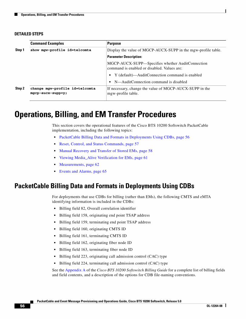
Operations, Billing, and EM Transfer Procedures
DETAILED STEPS
Operations, Billing, and EM Transfer ProceduresThis section covers the operational features of the Cisco BTS 10200 Softswitch PacketCable implementation, including the following topics:
• PacketCable Billing Data and Formats in Deployments Using CDBs, page 56
• Reset, Control, and Status Commands, page 57
• Manual Recovery and Transfer of Stored EMs, page 58
• Viewing Media_Alive Verification for EMs, page 61
• Measurements, page 62
• Events and Alarms, page 65
PacketCable Billing Data and Formats in Deployments Using CDBsFor deployments that use CDBs for billing (rather than EMs), the following CMTS and eMTA identifying information is included in the CDBs:
• Billing field 82, Overall correlation identifier
• Billing field 158, originating end point TSAP address
• Billing field 159, terminating end point TSAP address
• Billing field 160, originating CMTS ID
• Billing field 161, terminating CMTS ID
• Billing field 162, originating fiber node ID
• Billing field 163, terminating fiber node ID
• Billing field 223, originating call admission control (CAC) type
• Billing field 224, terminating call admission control (CAC) type
See the Appendix A of the Cisco BTS 10200 Softswitch Billing Guide for a complete list of billing fields and field contents, and a description of the options for CDB file-naming conventions.
Command Examples Purpose
Step 1 show mgw-profile id=telcomta Display the value of MGCP-AUCX-SUPP in the mgw-profile table.
Parameter Description:
MGCP-AUCX-SUPP—Specifies whether AuditConnection command is enabled or disabled. Values are:
• Y (default)—AuditConnection command is enabled
• N—AuditConnection command is disabled
Step 2 change mgw-profile id=telcomta mgcp-aucx-supp=y;
If necessary, change the value of MGCP-AUCX-SUPP in the mgw-profile table.
56PacketCable and Event Message Provisioning and Operations Guide, Cisco BTS 10200 Softswitch, Release 5.0
OL-12264-08

Operations, Billing, and EM Transfer Procedures
Reset, Control, and Status CommandsThis section describes the reset, control, and status commands for aggr and policy-server.
Reset
To provide the functionality of resetting the TCP connections to the CMTS and PS, the BTS 10200 implements a reset command for the AGGR (CMTS) or PS. The system closes and reinitiates the TCP connection and COPS session to the CMTS or PS when the operator executes the following CLI command:
reset aggr id=CMTS1;reset policy-server id=PS-DALLAS;
If an AGGR or POLICY-SERVER is in any operational state other than in service (INS), for example if the AGGR or POLICY-SERVER is operationally out of service (OOS) or transitioning between operational states, the system does not execute the reset. It responds to the reset command by displaying a failure message.
Control
The system implements control command for the AGGR. There are only two possible administrative states for AGGR (CMTS/PS) IN-SERVICE and OUT-OF-SERVICE.
For control out-of-service with mode set to forced/graceful, the Cisco BTS 10200 Softswitch closes the TCP connection (thus COPS session) to CMTS or PS when operator takes the AGGR out-of-service by executing the following CLI command. After you control the aggr or policy-server OOS, the BTS 10200 does not attempt to set up any new calls through this aggr or policy-server. Existing calls may or may not be affected depending upon the CMTS implementation.
control aggr id=CMTS1; target-state=OOS; mode=forced;control policy-server id=PS-DALLAS; target-state=OOS; mode=forced;
The system initiates a set up for TCP as well as a COPS connection to the CMTS or the PS when the operator brings the AGGR into in-service mode by executing the following CLI command:
control aggr id=CMTS1; target-state=INS; mode=forced;control policy-server id=PS-DALLAS; target-state=INS; mode=forced;
Status
The system shows the operational state when the operator queries the current status of TCP and COPS connection associated with the CMTS or PS:
status aggr id=CMTS1;status policy-server id=PS-DALLAS;
Example:
status aggr ID=c7246-777;
ID -> c7246-777OPER STATE -> AGGR IN ServiceRESULT -> ADM configure result in successREASON -> ADM executed successfully
57PacketCable and Event Message Provisioning and Operations Guide, Cisco BTS 10200 Softswitch, Release 5.0
OL-12264-08

Operations, Billing, and EM Transfer Procedures
For the STATUS AGGR command, the available displayed values include INS (in service), OOS (out of service), and CONNECTING. CONNECTING state means that the Cisco BTS 10200 Softswitch is reattempting to connect to the CMTS.
For a DQoS/PCMM subscriber, Cisco BTS 10200 first checks whether AGGR_ID is provisioned in the MGW table. If it's not provisioned in the MGW table, BTS 10200 looks for the AGGR_ID value provisioned in the SUBNET table (that is, the AGGR_ID value is resolved using the value provisioned in the SUBNET table).
If the AGGR_ID is provisioned (resolved), BTS 10200 checks the status of AGGR or POLICY_SERVER table. For a DQoS/PCMM call, if the AGGR or POLICY_SERVER operational state is not INS, and the BEST_EFFORT_ON_QOS_FAIL flag is set to N, the system drops the call. If the AGGR or POLICY_SERVER operational state is not INS, and the BEST_EFFORT_ON_QOS_FAIL flag is set to Y, the system continues the (DQoS/PCMM) call on a best-effort basis.
If the AGGR_ID is not provisioned in the MGW or SUBNET table, BTS 10200 lets the call to continue on a best-effort basis.
Note If the AGGR_ID is not provisioned for a tapped (CALEA) subscriber, then all non-emergency calls are blocked.
Manual Recovery and Transfer of Stored EMsThis section describes how to manually recover and transfer stored EM files from the CA to the RKS. This procedure must be used if communication to both RKS units goes down. Perform these procedures after communication is restored.
Recovering the Billing Files
Note For information on compliance with specific paragraphs of PacketCable standards and ECNs, contact your Cisco account team.
Billing data is normally transferred to the RKS on a real-time basis. In the unlikely event that communications with the RKS go down, alarms are raised and billing data files are written to a local drive on the Cisco BTS 10200 Softswitch (see the /opt/BTSem directory on the Call Agent (CA) that generated the EMs). If communications are not promptly restored, additional billing alarms of increasing severity are raised at time intervals of 1 hour (minor), 3 hours (major), and 5 hours (critical).
EMs that are not successfully transferred to the RKS are stored on the Call Agent. The system uses the naming conventions specified in PacketCable ECN EM-N-04.0186-3 for the stored EMs. Here is the format for the file name:
PKT_EM_<yyyymmddhhmmss>_<priority>_<record type>_<node id>_<sequence>.bin
The parameters are defined as follows:
• PKT_EM is fixed and does not change across files.
• yyyymmddhhmmss is a timestamp, where:
– yyyy is the year, such as 2005
– mm is the month, from 01 through 12
– hh is the hour, from 00 through 23
58PacketCable and Event Message Provisioning and Operations Guide, Cisco BTS 10200 Softswitch, Release 5.0
OL-12264-08

Operations, Billing, and EM Transfer Procedures
– mm is the minute, from 00 through 59
– ss is the second, from 00 through 59
• priority is always set to 3.
• record type is always set to 0.
• node id is the CMS ID or MGC ID. It must be five digits long and padded with leading 0s if necessary. (The system uses the CMS ID or the MGC ID depending on whether the file contains EMs generated by the CMS or the MGC function of the Call Agent.)
• sequence is the file sequence number. It must be six digits long, padded with leading 0s if necessary. (The CMS and MGC files are numbered independently.)
• .bin is the binary file type designation.
Here is an example of a typical EM file name:
PKT_EM_20050915103142_3_0_01234_000002.bin
All billing data generated during the period of the communication outage is stored in the /opt/BTSem directory. If communication with the RKS is lost for an extended period, the available disk space on the local Softswitch drives can begin to fill up with EM files. The system monitors the amount of space available on the disks and raises alarms of increasing severity when the disks are 50 percent (minor), 70 percent (major) and 100 percent (critical) full.
Note There can be billing data files on both CAs, primary and secondary, depending on whether there have been any switchovers during the loss of communication with the RKS.
We recommend that you monitor the available disk space on a regular basis to prevent the possible loss of billing data. If the disks become full, the data on the disk is preserved and new EMs are discarded.
Caution Do not allow the disk to become full. If you do not transfer the billing data files to the RKS, billing data might be lost. If EMs are discarded, they cannot be recovered and revenue could be lost.
Sending Billing Files to the RKS via FTP
To send billing files from the CA to the RKS, perform the following steps:
Step 1 On the CA, navigate to the subdirectory to which the billing data is written.
cd /opt/BTSem
Step 2 At the prompt, establish an FTP session with the RKS.
ftp <RKS name>
Step 3 When prompted, enter your user name and password for the RKS. The FTP prompt should appear.
Step 4 At the FTP prompt, enter bin to enable binary transfer:
bin
59PacketCable and Event Message Provisioning and Operations Guide, Cisco BTS 10200 Softswitch, Release 5.0
OL-12264-08

Operations, Billing, and EM Transfer Procedures
Step 5 On the RKS, navigate to the subdirectory to which the billing files will be written.
cd /.../.../<billing file subdirectory name>
Step 6 Place the applicable billing files in the billing files subdirectory.
put <billing-filenames>
Step 7 After the transfer is complete and the FTP prompt reappears, exit the FTP session.
bye
Comparing Checksums
To compare the checksums to ensure that the data was transferred correctly, perform the following steps:
Step 1 Log in to the RKS, using your user name and password for that system.
Step 2 Navigate to the subdirectory to which the billing data files were written.
cd /.../.../<billing file subdirectory name>
Step 3 List the files in the billing directory. The following command lists the files in reverse order by creation date:
ls -lrt
Step 4 Run a cksum on the files that were backed up.
cksum <billing-filename>
Step 5 Compare these cksum values to the corresponding cksum values on the CA.
a. If the cksum values are the same, the file transfer has completed without error.
b. If the cksum values are not the same, repeat all of the steps in the “Sending Billing Files to the RKS via FTP” section on page 59 and “Comparing Checksums” section on page 60.
If the cksum values are still different, contact Cisco TAC for assistance.
Content of EMs Sent to the RKS
Following is an example of a typical EM sent by the Cisco BTS 10200 Softswitch to an RKS. The format of the event-time field is yyyymmddhhmmss.mmm, where .mmm refers to milliseconds.
EM-Header (1):version: 4bci: 3378049121- 55555-58 (STD, -06:00:00)event-type: Signaling Start (1)
60PacketCable and Event Message Provisioning and Operations Guide, Cisco BTS 10200 Softswitch, Release 5.0
OL-12264-08

Operations, Billing, and EM Transfer Procedures
element-type: CMS (1)element-id: 55555zone: STD, -06:00:00sequence-number: 618event-time: 20070117125847.132status: 0priority: 128attribute-count: 6event-object: 1Direction-Indicator (37): Originating (1)
Viewing Media_Alive Verification for EMsUse the activity table to schedule and configure Media_Alive EMs. These EMs are used during longer-duration calls to verify that the media connection is still alive.
Step 1 Configure Media_Alive generation according to local requirements (example shown here):
add activity id=MEDIA-ALIVE-EM; freq=6H; start-time=HH:MM;
where:
• id—The value must be MEDIA-ALIVE-EM, which is a fixed system value listed in the Activity Base (activity-base) table.
Note You can view other tokens in the activity-base table by using the command show activity-base. However, you cannot change any values in that table.
• freq—Frequency. The number of times to schedule the specified EM Media_Alive activity.
• start-time—Time of day in the format HH:MM ranging from 00:00 to 23:59 (default is 00:00).
Note The activity table has several other tokens that support other EM Media_Alive options. For more detailed information about these options, see the Cisco BTS 10200 Softswitch Command Line Interface Reference Guide.
Step 2 To view the MEDIA-ALIVE-EM activity, enter the following command:
show activity id=MEDIA-ALIVE-EM;
Sample command line output:
ID=MEDIA-ALIVE-EM
FREQ=30 MINUTES
DAY_OF_MONTH=NA
DAY_OF_WEEK=NA
START_TIME=00:00
FIXED_TIME_INTERVAL=N
ENABLED=N
SO_ENABLED=N
61PacketCable and Event Message Provisioning and Operations Guide, Cisco BTS 10200 Softswitch, Release 5.0
OL-12264-08

Operations, Billing, and EM Transfer Procedures
RESTART_ENABLED=N
LAST_CHANGED=2004-10-20 16:45:30
MeasurementsSeveral traffic measurements pertain to the PacketCable implementation. For detailed descriptions see the Traffic Measurements section in the Cisco BTS 10200 Softswitch Operations and Maintenance Guide.
Creating Reports and Displays of Measurements
This section outlines the procedure for creating reports and displays of measurements. It uses the DQoS feature as an example. Additional details about measurement provisioning, reporting, and display commands for all features can be found in the Cisco BTS 10200 Softswitch Operations Guide and the Cisco BTS 10200 Softswitch Command Line Interface Reference Guide.
To create a report file of the DQoS counters for all time intervals in the period starting and ending at specific times, enter the following command. The system prepends the file with the string “Tm_” and writes the file to the /opt/ems/report directory on the active EMS.
report measurement-dqos-summary; start-time=[start-time]; end-time=[end-time]; aggr-id=[ID of the aggregation router (CMTS) for which data should be reported]; output=[desired file name for the report]; output-type=[CSV | XML];
where:
start-time and end-time have the format yyyy-mm-dd hh:mm:ss
CSV = comma-separated value
Note Time intervals can be every 5, 15, 30, or 60 minutes. This is provisionable in another command, change measurement-prov, as described later in this section.
Use any of the following commands to display DQoS counters on your monitor.
• To display DQoS counters for all time intervals in the past 48 hours for all CMTS IDs, enter the following command:
report measurement-dqos-summary; interval=ALL;
• To display DQoS counters tracked at every interval in the period starting at a specific start-time and for all aggregation IDs, enter the following command:
report measurement-dqos-summary; start-time=[start-time];
(start-time has a format of yyyy-mm-dd hh:mm:ss, and the end-time defaults to the most recent interval)
• To display DQoS counters for the most recent time interval for all aggregation IDs, enter the following command:
report measurement-dqos-summary;
(start-time and end-time both default to the most recent interval)
62PacketCable and Event Message Provisioning and Operations Guide, Cisco BTS 10200 Softswitch, Release 5.0
OL-12264-08

Operations, Billing, and EM Transfer Procedures
In this example, the system displays the most recent time interval for all aggregation IDs:
report measurement-dqos-summaryReply: Request was successful.TIMESTAMP 20020310184428DQOS_GATESET_ATTMP 10DQOS_GATESET_SUCC 9DQOS_GATE_COMMIT 9
In this example, the display token is used to specify desired counters (separated by commas):
report measurement-dqos-summary; display=DQOS_GATESET_ATTMP,DQOS_GATE_COMMIT;Reply: Request was successful.TIMESTAMP 20020310184428DQOS_GATESET_ATTMP 10DQOS_GATE_COMMIT 9
To manage the collection of DQoS measurements, use the following commands:
• To display the current provisioning settings of DQoS measurements (enabled or disabled status), enter the following command:
show measurement-prov type=DQOS;
• To change the current provisioning settings of DQoS measurements (enabled or disabled status) and/or the time interval (5, 15 [default], 30, or 60 minutes), enter the following command:
change measurement-prov type=dqos; enable=yes; time-interval=30;
Measurements for the DQoS Feature on COPS Interface
The system supports a number of measurements related to gate coordination over DQoS and PCMM interfaces. See the complete list of measurements in the “Traffic Measurements” chapter of the Cisco BTS 10200 Softswitch Operations and Maintenance Guide.
The Cisco BTS 10200 Softswitch tracks and reports measurements separately for each of the CMTS units (aggregation routers) and PS units it supports.
Measurements for the EM Feature
The system supports a number of measurements related to EMs. Use the following CLI command to retrieve these measurements:
report measurement-em-summary
A typical command and system response are shown below:
report measurement-em-summary
TIMESTAMPCALL_AGENT_IDCONDITIONBILLING_EM_ACKED BILLING_EM_LOGGED BILLING_EM_RETRANS
2003-07-10 16:15:00CA146Normal233
63PacketCable and Event Message Provisioning and Operations Guide, Cisco BTS 10200 Softswitch, Release 5.0
OL-12264-08

Operations, Billing, and EM Transfer Procedures
See the complete list of measurements in the “Traffic Measurements” chapter of the Cisco BTS 10200 Softswitch Operations and Maintenance Guide.
64PacketCable and Event Message Provisioning and Operations Guide, Cisco BTS 10200 Softswitch, Release 5.0
OL-12264-08
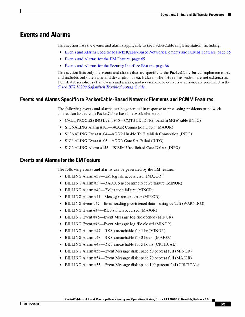
Operations, Billing, and EM Transfer Procedures
Events and AlarmsThis section lists the events and alarms applicable to the PacketCable implementation, including:
• Events and Alarms Specific to PacketCable-Based Network Elements and PCMM Features, page 65
• Events and Alarms for the EM Feature, page 65
• Events and Alarms for the Security Interface Feature, page 66
This section lists only the events and alarms that are specific to the PacketCable-based implementation, and includes only the name and description of each alarm. The lists in this section are not exhaustive.Detailed descriptions of all events and alarms, and recommended corrective actions, are presented in the Cisco BTS 10200 Softswitch Troubleshooting Guide.
Events and Alarms Specific to PacketCable-Based Network Elements and PCMM Features
The following events and alarms can be generated in response to processing problems or network connection issues with PacketCable-based network elements:
• CALL PROCESSING Event #15—CMTS ER ID Not found in MGW table (INFO)
• SIGNALING Alarm #103—AGGR Connection Down (MAJOR)
• SIGNALING Event #104—AGGR Unable To Establish Connection (INFO)
• SIGNALING Event #105—AGGR Gate Set Failed (INFO)
• SIGNALING Alarm #155—PCMM Unsolicited Gate Delete (INFO)
Events and Alarms for the EM Feature
The following events and alarms can be generated by the EM feature.
• BILLING Alarm #38—EM log file access error (MAJOR)
• BILLING Alarm #39—RADIUS accounting receive failure (MINOR)
• BILLING Alarm #40—EM encode failure (MINOR)
• BILLING Alarm #41—Message content error (MINOR)
• BILLING Event #42—Error reading provisioned data—using default (WARNING)
• BILLING Event #44—RKS switch occurred (MAJOR)
• BILLING Event #45—Event Message log file opened (MINOR)
• BILLING Event #46—Event Message log file closed (MINOR)
• BILLING Alarm #47—RKS unreachable for 1 hr (MINOR)
• BILLING Alarm #48—RKS unreachable for 3 hours (MAJOR)
• BILLING Alarm #49—RKS unreachable for 5 hours (CRITICAL)
• BILLING Alarm #53—Event Message disk space 50 percent full (MINOR)
• BILLING Alarm #54—Event Message disk space 70 percent full (MAJOR)
• BILLING Alarm #55—Event Message disk space 100 percent full (CRITICAL)
65PacketCable and Event Message Provisioning and Operations Guide, Cisco BTS 10200 Softswitch, Release 5.0
OL-12264-08

EM Generation Details and Content
Events and Alarms for the Security Interface Feature
The following events and alarms can be generated in response to PacketCable-related security signaling conditions:
• SECURITY Alarm #3—IPsec connection down (MAJOR)
• SECURITY Event #4—IPsec MTA Key Establish Error (WARNING)
• SECURITY Event #5—IPsec outgoing SA not found (WARNING)
EM Generation Details and ContentThis section describes the internal processes for EM generation and the content of the EMs. These processes are based on the PacketCable Event Message Specification PKT-SP-EM-I10-040721.
Note The system complies with the RKS EM billing interface requirements of PKT-SP-EM-I10-040721. For information on compliance with specific paragraphs of PacketCable standards, contact your Cisco account team.
EM Generation Details
Table 2 lists the EMs generated by call configuration.
Table 3 lists the EMs that can be generated by the CMS and MGC.
Table 2 EMs Generated by Call Configuration
Cisco BTS 10200 Softswitch Generates EMs for ...
Call Configuration
On-net to On-net On-net to Off-net Off-net to On-net
Originating CMS X X
Terminating CMS X X
Originating MGC X
Terminating MGC X
Table 3 EMs Generated by Logical Entity
Event Message CMS MGC
Signaling_Start X X
Signaling_Stop X X
Interconnect_Start X
Interconnect_Stop X
Call_Answer X X
Call_Disconnect X X
Database_Query X
Service_Instance X
66PacketCable and Event Message Provisioning and Operations Guide, Cisco BTS 10200 Softswitch, Release 5.0
OL-12264-08
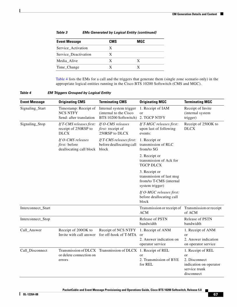
EM Generation Details and Content
Table 4 lists the EMs for a call and the triggers that generate them (single zone scenario only) in the appropriate logical entities running in the Cisco BTS 10200 Softswitch (CMS and MGC).
Service_Activation X
Service_Deactivation X
Media_Alive X X
Time_Change X X
Table 3 EMs Generated by Logical Entity (continued)
Event Message CMS MGC
Table 4 EM Triggers Grouped by Logical Entity
Event Message Originating CMS Terminating CMS Originating MGC Terminating MGC
Signaling_Start Timestamp: Receipt of NCS NTFYSend: after translation
Internal system trigger (internal to the Cisco BTS 10200 Softswitch)
1. Receipt of IAM or2. TGCP NTFY
Receipt of Invite (internal system trigger)
Signaling_Stop If T-CMS releases first: receipt of 250RSP to DLCX
If O-CMS releases first: before deallocating call block
If O-CMS releases first: receipt of 250RSP to DLCX
If T-CMS releases first: before deallocating call block
If T-MGC releases first: upon last of following events:
1. Receipt or transmission of RLC from/to SG
2. Receipt or transmission of Ack for TGCP DLCX
3. Receipt or transmission of last msg from/to T-CMS (internal system trigger)
If O-MGC releases first: before deallocating call block
Receipt of 250OK to DLCX
Interconnect_Start Transmission or receipt of ACM
Transmission or receipt of ACM
Interconnect_Stop Release of PSTN bandwidth
Release of PSTN bandwidth
Call_Answer Receipt of 200OK to Invite with call answer
Receipt of NCS NTFY for off-hook of T-MTA
1. Receipt of ANMor2. Answer indication on operator service
1. Receipt of ANMor2. Answer indication on operator service
Call_Disconnect Transmission of DLCX or delete connection on errors
Transmission of DLCX 1. Receipt of RELor2. Transmission of BYE for REL
1. Receipt of RELor2. Disconnect indication on operator service trunk disconnect
67PacketCable and Event Message Provisioning and Operations Guide, Cisco BTS 10200 Softswitch, Release 5.0
OL-12264-08

EM Generation Details and Content
Table 5 lists the PacketCable 1.0 features, the EMs generated for them, and the event that triggers the message. Some of the triggering events include the logical entities—Originating CMS (O-CMS) and Terminating CMS (T-CMS)—running in the Cisco BTS 10200 Softswitch.
Database_Query Receipt of response from DB or intelligent peripheral
Receipt of response from DB or intelligent peripheral
— —
Service_Instance Operation of service Operation of service — —
Service_Activation Successful activation Successful activation — —
Service_Deactivation Successful deactivation
Successful deactivation
— —
Media_Alive Periodic, based on provisioned parameters
Periodic, based on provisioned parameters
Periodic, based on provisioned parameters
Periodic, based on provisioned parameters
Time_Change When time is adjusted When time is adjusted When time is adjusted When time is adjusted
Table 4 EM Triggers Grouped by Logical Entity (continued)
Event Message Originating CMS Terminating CMS Originating MGC Terminating MGC
Table 5 PacketCable 1.0 Features and Associated EMs
EMs Sent in Addition to Basic Call EMs
CommentsPacketCable 1.0 Feature Event Message Trigger
911 service—Similar to on-net to off-net call on a unique trunk group ID.
None — —
Other N11 services—Similar to above None — —
Database Query
a. Send all database queries to PSTN on special trunk
None — —
68PacketCable and Event Message Provisioning and Operations Guide, Cisco BTS 10200 Softswitch, Release 5.0
OL-12264-08

EM Generation Details and Content
b. Query database and route accordingly
db_query O-CMS on receipt of response to database dip.
Query types:
1 = Toll-free number lookup
2 = Local number portability (LNP) number lookup
3 = Calling name delivery lookup
If the query is successful—that is, if the query returns the calling party’s name—the query type (1, 2, or 3) is included in the EM:
• For types 1 and 2, the value in the EM Return_Number field contains the new called party digits.
• For type 3, the value in the EM Return_Number field contains a valid string, such as “O” or “P”. 1
If the query fails, no EM is sent.
Operator Service
a. 0– service (no digit after 0) None Called party number 0 is replaced by Operator Service Provider number.
Only call routing.
b. 0+ service (digits after 0, not needed in PacketCable 1.0)
Only call routing.
Call block service (with new call to announcement server)
Service instance O-CMS and T-CMS decide to block call.
If announcement server is connected, event messages are generated for call with same BCID.
Table 5 PacketCable 1.0 Features and Associated EMs (continued)
EMs Sent in Addition to Basic Call EMs
CommentsPacketCable 1.0 Feature Event Message Trigger
69PacketCable and Event Message Provisioning and Operations Guide, Cisco BTS 10200 Softswitch, Release 5.0
OL-12264-08

EM Generation Details and Content
Call waiting
a. Announcement server on net Service instance O-CMS and T-CMS when call waiting is initiated. Second call BCID for service instance.
Only two calls, one active and one on hold, are required. Each half-call generates an EM. A half-call for an on-net announcement server for call waiting tone need not generate an EM. Here is an example of a call scenario:
A calls B, C calls A: (A −> B, C −> A) BCID1 for A(O), other leg BCID2BCID2 for B(T), other leg BCID1BCID3 for C(O), other leg BCID4BCID4 for A(T), other leg BCID3
BCID4 for CW service instance, related BCID = BCID1
b. Announcement server on PSTN Not supported — —
Call forwarding Service instance CMS (O/T) when forwarded call leg is initiated.
A calls B, B forwards to C:(A −> B −> C)BCID1 for A(O), other leg BCID2BCID2 for B(T), other leg BCID1BCID3 for B(O), other leg BCID4BCID4 for C(T), other leg BCID3BCID3 for CFW service instance, related BCID=BCID2
Return call (with caller ID privacy restriction)
a. Announcement server on net Service instance O-CMS on feature initiation.
Note CMS-CMS signaling is not supported in this release.
b. Announcement server on PSTN Not supported —
Repeat call (*66) CMS-CMS signaling is not supported in this release.
a. Announcement server on net Service instance Repeat call is initiated. Separate BCID for service instance.
b. Announcement server on PSTN Not supported — —
Voice mail (voice mail server on off-net) None — —
Deposit and retrieval: similar to on-net to off-net call
None — —
Table 5 PacketCable 1.0 Features and Associated EMs (continued)
EMs Sent in Addition to Basic Call EMs
CommentsPacketCable 1.0 Feature Event Message Trigger
70PacketCable and Event Message Provisioning and Operations Guide, Cisco BTS 10200 Softswitch, Release 5.0
OL-12264-08

EM Generation Details and Content
Message waiting indicator None — No event messages for message waiting.
Privacy indicator Signaling start — Indicates whether the system populates field 12 of the EM with the calling party service (privacy setting) for the calling party.
This attribute uses the previously undefined field 12 in PKT-SP-EM-I10-040721.
See the “EM Content” section on page 72 for additional requirements.
1. “O” = Name is out of area, unknown, or not available. “P” = Name presentation is restricted.
Table 5 PacketCable 1.0 Features and Associated EMs (continued)
EMs Sent in Addition to Basic Call EMs
CommentsPacketCable 1.0 Feature Event Message Trigger
71PacketCable and Event Message Provisioning and Operations Guide, Cisco BTS 10200 Softswitch, Release 5.0
OL-12264-08

EM Generation Details and Content
EM Content
The following EMs for a call contain the attributes listed, and are based on the four logical entities running in the Cisco BTS 10200 Softswitch: Originating CMS (O-CMS), Terminating CMS (T-CMS), Originating MGC (O-MGC), and Terminating MGC (T-MGC).
Signaling Start Attribute O-CMS T-CMSO-MGC (Off-net to On-net Call)
T-MGC (On-net to Off-net Call)
Direction indicator X X X X
MTA endpoint name Originating Terminating Name of endpoint (EP) in MGW
Name of endpoint (EP) in MGW
Calling party number X X X X
Calling party service 1
1.The calling party service attribute uses the previously undefined field 12 (see PKT-SP-EM-I10-040721). It is an unsigned integer, 4 bytes in length. If (a) the EM-PRIVACY-IND-SUPP token in the CA-CONFIG table is set to Y, and (b) the calling party number field in the EM is populated, then the system populates the calling party service field as follows: If the presentation status (PS) of the calling party is set to private, the calling party service field is set to 1; if the PS is set to public, the calling party service field is set to 0. If the EM-PRIVACY-IND-SUPP token is set to N (default), or if the calling party number is not present in the Signaling Start EM, or the PS is not present in the incoming message, the system does not populate the calling party service field.
X X X X
Called party number X X X X
Routing number X X X X
Location routing number (LRN)
X X X X
Carrier identification code (CIC)
X X
Trunk group ID X X
Jurisdiction information parameter (JIP)
X X X
Ported-in calling number X
Ported-in called number X
Calling party NP source X
Called party NP source X
Billing type (measured rate or flat rate)
X
Signaling Stop Attribute O-CMS T-CMSO-MGC (Off-net to On-net Call)
T-MGC (On-net to Off-net Call)
BCID of T-CMS or T-MGC X X
BCID of O-CMS or O-MGC X X
FEID of T-CMS or T-MGC X X
FEID of O-CMS or O-MGC X X
72PacketCable and Event Message Provisioning and Operations Guide, Cisco BTS 10200 Softswitch, Release 5.0
OL-12264-08

EM Generation Details and Content
Note Only a limited number of service names are specified in the PacketCable 1.0 specification. The Cisco BTS 10200 Softswitch supports many other features; however, it does not send EMs for those features to a standard Record Keeping Server (RKS) because the feature codes for those features have not yet been defined by PacketCable.
Interconnect Start Attribute O-CMS T-CMSO-MGC (Off-net to On-net Call)
T-MGC (On-net to Off-net Call)
Routing number X X
CIC X X
Trunk group ID X X
Interconnect Stop Attribute O-CMS T-CMSO-MGC (Off-net to On-net Call)
T-MGC (On-net to Off-net Call)
CIC X X
Trunk group ID X X
Call Answer Attribute O-CMS T-CMSO-MGC (Off-net to On-net Call)
T-MGC (On-net to Off-net Call)
Charge number X X X X
BCID of T-CMS or T-MGC X X
FEID of T-CMS or T-MGC X X
BCID of O-CMS or O-MGC X X
FEID of O-CMS or O-MGC X X
Call Disconnect Attribute O-CMS T-CMSO-MGC (Off-net to On-net Call)
T-MGC (On-net to Off-net Call)
Call termination cause X X X X
Service Instance Attribute O-CMS T-CMSO-MGC (Off-net to On-net Call)
T-MGC (On-net to Off-net Call)
Service name (plus specified attributes in the table below)
X X
Account code X
Authorization code X
73PacketCable and Event Message Provisioning and Operations Guide, Cisco BTS 10200 Softswitch, Release 5.0
OL-12264-08

EM Generation Details and Content
Service- Specific Attributes Attribute
Call Forward
Call Waiting
Repeat Call
Return Call Call Block
Three- Way Call
Privacy Indicator
Related BCID X X X
Charge number X X X X X
1st call calling party number
X
2nd call calling party number
X
Called party number X
Routing number X X
Calling party number X X X
Calling party service X X X
Termination cause X
Service Activation Attribute O-CMS T-CMS
O-MGC(Off-net to On-net Call)
T-MGC(On-net to Off-net Call)
Service name (plus specified attributes in the following table)
X X
Service-Specific Attributes Attribute Call Forward Call Waiting Call Block
Customer Originated Trace
Charge number X X X X
Calling party number X X X X
Forwarded number X
Service Deactivation Attribute O-CMS T-CMS
O-MGC(Off-net to On-net Call)
T-MGC(On-net to Off-net Call)
Service name (plus specified attributes in the table below)
X X
Service-Specific Attributes Attribute Call Forward Call Waiting Call Block
Charge number X X X
Calling party number X X X
74PacketCable and Event Message Provisioning and Operations Guide, Cisco BTS 10200 Softswitch, Release 5.0
OL-12264-08

EM Generation Details and Content
Database Query Attribute O-CMS T-CMS
O-MGC(Off-net to On-net Call)
T-MGC(On-net to Off-net Call)
Database ID X X
Query type X X
Called party number X X
Returned number X X
Activity Attribute O-CMS T-CMS
O-MGC(Off-net to On-net Call)
T-MGC(On-net to Off-net Call)
Media alive X X X X
Time Change Attribute O-CMS T-CMS
O-MGC(Off-net to On-net Call)
T-MGC(On-net to Off-net Call)
Time adjustment X X X X
75PacketCable and Event Message Provisioning and Operations Guide, Cisco BTS 10200 Softswitch, Release 5.0
OL-12264-08

References
References
Industry Standards
Note For information on compliance with specific paragraphs of PacketCable standards and ECNs, contact your Cisco account team.
Standards Title
IETF RFC 2748 The COPS (Common Open Policy Service) Protocol, January 2000
PKT-SP-CODEC-I04-021018 PacketCable Audio/Video Codecs Specification, October 18, 2002
PKT-SP-DQOS-I07-030815 PacketCable Dynamic Quality of Service Specification, August 15, 2003
PKT-SP-MGCP-I08-030728 PacketCable Network-Based Call Signaling Protocol Specification, July 28, 2003
PKT-SP-TGCP-I05-030728 PacketCable PSTN Gateway Call Signaling Protocol Specification, July 28, 2003
PKT-SP-EM-I10-040721
Note Compliant with the RKS EM billing interface requirements of PKT-SP-EM-I10-040721.
PacketCable Event Message Specification, July 21, 2004
EM-N-04.0186-3
Note Compliant with the file-naming convention in EM-N-04.0186-3.
CableLabs Engineering Change (EC) Form
PKT-SP-SEC-I09-030728 PacketCable Security Specification, July 28, 2003
PKT-SP-ESP-I01-991229 PacketCable Electronic Surveillance Specification, December 29, 1999
PKT-SP-MM-I02-040930 PacketCable Multimedia Specification, September 30, 2004
CCVP, the Cisco logo, and Welcome to the Human Network are trademarks of Cisco Systems, Inc.; Changing the Way We Work, Live, Play, and Learn isa service mark of Cisco Systems, Inc.; and Access Registrar, Aironet, Catalyst, CCDA, CCDP, CCIE, CCIP, CCNA, CCNP, CCSP, Cisco, the CiscoCertified Internetwork Expert logo, Cisco IOS, Cisco Press, Cisco Systems, Cisco Systems Capital, the Cisco Systems logo, Cisco Unity,Enterprise/Solver, EtherChannel, EtherFast, EtherSwitch, Fast Step, Follow Me Browsing, FormShare, GigaDrive, HomeLink, Internet Quotient, IOS,iPhone, IP/TV, iQ Expertise, the iQ logo, iQ Net Readiness Scorecard, iQuick Study, LightStream, Linksys, MeetingPlace, MGX, Networkers,Networking Academy, Network Registrar, PIX, ProConnect, ScriptShare, SMARTnet, StackWise, The Fastest Way to Increase Your Internet Quotient,and TransPath are registered trademarks of Cisco Systems, Inc. and/or its affiliates in the United States and certain other countries.
All other trademarks mentioned in this document or Website are the property of their respective owners. The use of the word partner does not imply apartnership relationship between Cisco and any other company. (0711R)
76PacketCable and Event Message Provisioning and Operations Guide, Cisco BTS 10200 Softswitch, Release 5.0
OL-12264-08