pad diameter: ø40, ø50, ø63, ø80, ø100, ø125content2.smcetech.com/pdf/zpt_zpx_hb_eu.pdf ·...
TRANSCRIPT

Series ZPT/ZPX Pad diameter: ø40, ø50, ø63, ø80, ø100, ø125
Large Size Bellows Style Vacuum Pad
For automotive production lineFor transfer of CRT For transfer of cardboard box
3.9-85
ZP
ZX
ZR
ZM
ZH
ZU
ZL
ZF
ZCU
CYVVacuumrelated

50°
50°
60°
60°
50°
0 to 120
–30 to 250
0 to 60
0 to 250
–20 to 150
NBR
Silicone rubber
Urethane rubber
Fluorine rubber
EPR
ItemMaterial
DurometerHS (±5°)
Temperaturerange (°C)
Oil resistance(benzol)
Oil resistance(gasoline)
Alkaliresistance
Acidresistance
Weatherability Ozoneresistance
Abrasionresistance
WaterproofSolvents
(benzene, toluene)
Pad Materials and Characteristics
The above table covers only general characteristics of subject rubber materials.Pad material used SMC pass nominal JIS material standards; however, actual performance depends on operating conditions.
Male thread
Female thread
—
Female thread
Common
Female thread
Female threadFemale thread
With buffer
Female thread
Lateral Vacuum entryVertical Vacuum entry
Buffer mounting(Male thread)
P.3.9-88 to 3.9-90 P.3.9-88 to 3.9-90
P.3.9-91 to 3.9-92
P.3.9-93 to 3.9-94
P.3.9-95 to 3.9-96
Pad diameter: ø40, ø50, ø63, ø80, ø100, ø125Pad material: NBR, Silicone rubber, Urethane rubber,
Fluorine rubber, EPR
Buffer
Mounting
Vacuum entry
Large Size Bellows Style Vacuum Pad
Series ZPT/ZPX
ZPTSeries
ZPXSeries
25
50
75
100
Paddia.
Bufferstroke
ø40 ø50 ø63 ø80 ø100 ø125
Buffer stroke
—
Buffer mounting(Male thread)
With buffer—
— — — —
: Little or no influence �: Can be used depending on conditions. X: Not suitable
X
X
X X
X
X
X X
X
X
X
X
X
X
X
X
X
X
3.9-86

Interchangeable with flat pad with ribs for heavy loads
Possible adsorption to cylindrical loads with easy fit to the load shape.
Pad shape permits adsorption to sloped surfaces.
•When work shape or angles are transformed during adsorption or transportion. (Example of a cardboard box)
•When adsorbed surface of work is sloped. (Maximum angle: 5°∗)
∗Regard values mentioned above as reference only, since actual valves may depend on operating conditions.
When changing to a different shape pad due to load change, the pad can be easily interchanged.
Flat pad with ribs for heavy load Bellows pad for heavy load
∗Pushing force for adsorption is almost equivalent to return force of buffer spring.
Possible combination Same pad diameter, ø40 and ø50, ø63 and ø80, ø100 and ø125
ZP 40HB�
50HB�
63HB�
80HB�
100HB�
125HB�
Model Dia. of cylindrical work which can be absorbed: øA(1)
ø80 or more
ø100 or more
ø120 or more
ø160 or more
ø180 or more
ø230 or more
Table 1: Diameter of cylindrical workwhich can be absorbed. (Reference value)
Note 1) Consult SMC when requiring a diameter smaller than shown in table.Note 2) Regard values mentioned above as reference only, since actual valves may depend on operating conditions.
Diam
eter of cylindrical work
which can be absorbed: øA
3.9-87
Large Size Bellows Style Series ZPT/ZPX
ZX
ZR
ZM
ZY
ZH
ZU
ZL
ZF
ZP
ZCU
CYVVacuumrelated

VerticalVacuum entry direction
Connection
Vacuum entry port
Mo
un
tin
g Male thread
M14 X 1
M16 X 1.5
M16 X 1.5
Rc(PT) 1/8
ø40, ø50
ø63, ø80
ø100, ø125
Pad dia. (mm)
Material (colour)
Durometer
Specifications
Series ZPT Without Buffer
VerticalVacuum
Entry
M8/M10
M8/M10/M12/M16 X 1.5
M12/M16 X 1.5
Use connection for mounting
Pad Style
Part No.
ZPT40HBN-A14-B 8-B10
ZPT50HBN-A14-B 8-B10
ZPT63HBN-A16-B 8-B10-B12-B16
Weight
73
40
39
89
56
55
155
121
120
118
116
Part No.
ZPT 80HBN-A16-B 8-B10-B12-B16
ZPT100HBN-A16-B12-B16
ZPT125HBN-A16-B12-B16
Weight
195
161
160
158
156
396
347
345
580
531
529
Weight Table
Pad dia.
ø40ø50ø63ø80
ø100ø125
Silicone
–1
–2
–3
–6
–12
–22
(g)
Urethane
+1
+1
+2
+2
+4
+7
Fluorine
+10
+19
+37
+61
+121
+228
0
0
0
0
–1
–3
EPR
Add NBR weight to below table for other materials.
How to Order
HB
40
50
63
80
100
125
ø40
ø50
ø63
ø80
ø100
ø125
N
S
U
F
E
A14
A16
B 8
B10
B12
B16
Large SizeBellows Style
NBR
ZPT 40 HB N A14
Threaddia.
ø40, ø50, ø63, ø80, ø100, ø125
NBR (black), Silicone rubber (white), Urethane rubber (brown),Fluorine rubber (black with mark F), EPR (black with mark E)
NBR/Silicon rubber/EPR (50°), Urethane/Fluorine rubber (60°)
Pad dia. (mm)
Pad styleLarge size bellows
MaterialNBR
Silicone rubber
Urethane rubber
Fluorine rubber
EPR
Vacuum entry/ Mountingthread diameter
M14 X 1
M16 X 1.5
M 8
M10
M12
M16 X 1.5
ø40/ø50
—
—
—
—
—
—
—
ø63/ø80 ø100/ø125
Female thread
3.9-88
A40
50
(mm)
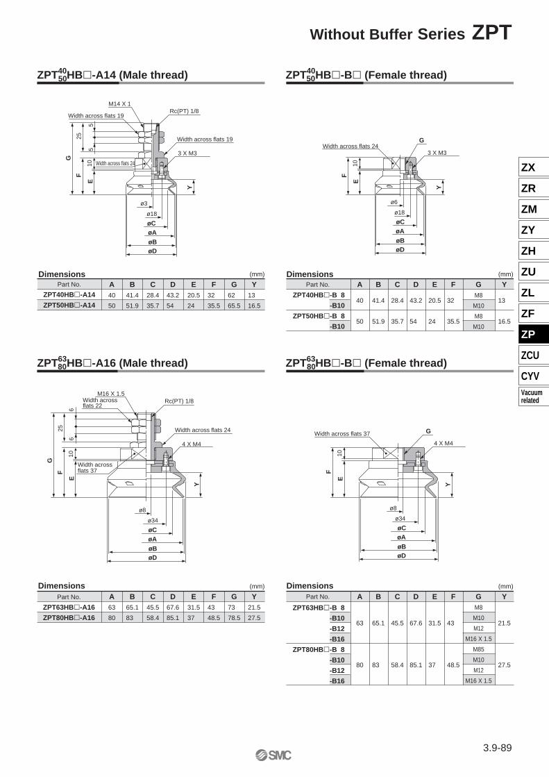
ZPT40HB�-A14 (Male thread)50
B41.4
51.9
C28.4
35.7
D43.2
54
E20.5
24
F32
35.5
G62
65.5
Y13
16.5
A
40
50
(mm)
Part No.
ZPT40HB�-B� (Female thread)50
B
41.4
51.9
C
28.4
35.7
D
43.2
54
E
20.5
24
F
32
35.5
GM8
M10
M8
M10
Y
13
16.5
A63
80
(mm)
Part No.
ZPT63HB�-A16
ZPT80HB�-A16
ZPT63HB�-A16 (Male thread)80
B65.1
83
C45.5
58.4
D67.6
85.1
E31.5
37
F43
48.5
G73
78.5
Y21.5
27.5
A
63
80
(mm)
Part No. B
65.1
83
C
45.5
58.4
D
67.6
85.1
E
31.5
37
F
43
48.5
GM8
M10
M12
M16 X 1.5
M85
M10
M12
M16 X 1.5
Y
21.5
27.5
ø3
ø18
øCøAøBøD
E
F
10
G
25
55
Y
G
ø6
ø18
øCøAøBøD
Y
E10
F
ø8
ø34
øCøAøBøD
E
F
10
G
25
66
Y
G
ø8
ø34
øCøAøBøD
E10
F
Y
Part No.
ZPT40HB�-A14
ZPT50HB�-A14ZPT40HB�-B 8
-B10
ZPT50HB�-B 8
-B10
ZPT63HB�-B� (Female thread) 80
ZPT63HB�-B 8
-B10
-B12
-B16
ZPT80HB�-B 8
-B10
-B12
-B16
M14 X 1
Width across flats 19
Width across flats 24
Rc(PT) 1/8
Width across flats 19
3 X M3Width across flats 24
3 X M3
Width across flats 22
M16 X 1.5Rc(PT) 1/8
Width across flats 24
4 X M4
Width across flats 37
Width across flats 37
4 X M4
Dimensions Dimensions
Dimensions Dimensions
3.9-89
Without Buffer Series ZPT
ZX
ZR
ZM
ZY
ZH
ZU
ZL
ZF
ZP
ZCU
CYVVacuumrelated

A100
125
(mm)
ZPT100HB�-A16 (Male thread)125
B103
128.5
C68.5
88.5
D107
135
E47.5
56
F60.5
69
G90.5
99
Y35.5
44
A
100
125
(mm)
Part No. B
103.1
128.5
C
68.6
88.6
D
106.7
135
E
47.5
56
F
60.5
69
GM12
M16 X 1.5
M12
M16 X 1.5
Y
35.5
44
ZPT100HB�-B12
-B16
ZPT125HB�-B12
-B16
E
F
11
G
25
66
ø8
ø40
øCøAøBøD
Y
G
ø10
ø40
øCøAøBøD
E
F
11
Y
Part No.
ZPT100HB�-A16
ZPT125HB�-A16
ZPT100HB�-B� (Female thread)125
Dimensions Dimensions
Width across flats 22
Width across flats 24
M16 X 1.5
Rc(PT) 1/8
4 X M5
Width across flats 60
Width across flats 60 4 X M5
3.9-90
Series ZPT

HB
B01
40
50
63
80
100
125
ø40
ø50
ø63
ø80
ø100
ø125
N
S
U
F
E
A18
A22
25
50
75
100
Series ZPT
ZPT40HBNJ25-B01-A1850-B01-A1875-B01-A18
ZPT50HBNJ25-B01-A1850-B01-A1875-B01-A18
ZPT63HBNJ25-B01-A1850-B01-A1875-B01-A18
ZPT80HBNJ25-B01-A18
127
147
168
143
163
201
208
228
249
231
268
289
535
575
620
659
719
759
804
843
ZPT 80HBNJ50-B01-A1875-B01-A18
ZPT100HBNJ25-B01-A2250-B01-A2275-B01-A22100-B01-A22
ZPT125HBNJ25-B01-A2250-B01-A2275-B01-A22100-B01-A22
6.9N
11.8N
10N
15N
ZPT 40 HB N J 25 B01 A18
With Buffer
ø40, ø50
ø63, ø80
ø100, ø125
Specifications
Vacuum entry direction
Connection
Vacuum entry port
Mo
un
tin
g
Thre
ad d
ia.
ø40 to ø80
ø100, ø125Buffer stroke
Buffer style Rotating (J)
25, 50, 75 (mm)
25, 50, 75, 100 (mm)
Pad Style
Pad dia. (mm)
Material (colour)
Durometer
ø40, ø50, ø63, ø80, ø100, ø125
NBR (black), Silicone rubber (white), Urethane rubber (brown),Fluorine rubber (black with mark F), EPR (black with mark E)
NBR/Silicone rubber/EPR (50°), Urethane/Fluorine rubber (60°)
Vertical
Male thread
M18 X 1.5
M18 X 1.5
M22 X 1.5
Rc(PT) 1/8
ø40ø50ø63ø80
ø100ø125
EPR
NBR
Weight Table
Part No. Weight Part No. Weight
Add NBR weight to below table for other materials.
Pad dia. Silicone Urethane Fluorine
How to Order
(g)
–1
–2
–3
–6
–12
–22
+1
+1
+2
+2
+4
+7
+10
+19
+37
+61
+121
+228
0
0
0
0
–1
–3
Pad dia. (mm)
Pad style
Spring force
MaterialApplicable buffer stroke (Rotating)
Vacuum entry
Mounting thread diameter
First mounting load
Second mounting load
First mounting load
Second mounting load
Large size bellows NBR
Silicone rubber
Urethane rubber
Fluorine rubber
EPR
M18 X 1.5 (ø40 to ø80)
M22 X 1.5 (ø100, ø125)
Rc(PT) 1/8
ø40
—
ø50
—
ø63
—
ø80
—
ø100 ø125Stroke
ø40 to ø80
ø100, ø150
Large sizeBellows Style
VerticalVacuum
Entry
3.9-91
ZX
ZR
ZM
ZY
ZH
ZU
ZL
ZF
ZP
ZCU
CYVVacuumrelated

A
40
50
(mm)
ZPT40HB�J�-B01-A18 (Male thread)50
B
41.4
51.9
C
28.4
35.7
D
43.2
54
E
20.5
24
F
32
35.5
G72
107
143
75.5
110.5
146.5
Y
13
16.5
H127.5
162.5
198.5
131
166
202
ZPT63HB�J�-B01-A18 (Male thread)80
A
63
80
(mm)
B
65.1
83
C
45.5
58.5
D
67.6
85.1
E
31.5
37
F
43
48.5
G83
118
154
88.5
123.5
159.5
Y
21.5
27.5
H138.5
173.5
209.5
144
179
215
ZPT100HB�J�-B01-A22 (Male thread)125
A
100
125
(mm)
B
103.1
128.5
C
68.6
88.6
D
106.7
135
E
47.5
56
F
60.5
69
G104.5
140.5
180.5
215.5
113
149
189
224
Y
35.5
44
H178.5
214.5
254.5
289.5
187
223
263
298
ZPT40HB�J25-B01-A18
50-B01-A18
75-B01-A18
ZPT50HB�J25-B01-A18
50-B01-A18
75-B01-A18
ZPT63HB�J25-B01-A18
50-B01-A18
75-B01-A18
ZPT80HB�J25-B01-A18
50-B01-A18
75-B01-A18
E
F
11
G
H
50
9.5
10
9.5
ø4
ø40
øCøAøBøD
Y
ø3
ø18
øCøAøBøD
YE
F
10
G
H
35
9
10
9
ø3
ø34
øCøAøBøD
Y
E
F
10
G
H
35
9
109
Rc(PT) 1/8Width across flats 14
Width across flats 27
Width across flats 16Width across flats 24
M18 X 1.5
3 X M3
Rc(PT) 1/8Width across flats 14
Width across flats 27
Width across flats 16
Width across flats 37
M18 X 1.5
4 X M4
Dimensions Dimensions
Dimensions
Part No. Part No.
Part No.
Rc(PT) 1/8Width across flats 17
Width across flats 30
Width across flats 19
Width across flats 60
M22 X 1.5
4 X M5
ZPT100HB�J25-B01-A22
50-B01-A22
75-B01-A22
100-B01-A22
ZPT125HB�J25-B01-A22
50-B01-A22
75-B01-A22
100-B01-A22
3.9-92
Series ZPT

Series ZPX
ZPX40HBN-B01-B 8-B10
ZPX50HBN-B01-B 8-B10
ZPX63HBN-B01-B10-B12
150
152
166
164
235
225
ZPX 80HBN-B01-B10-B12
ZPX100HBN-B01-B10-B12
ZPX125HBN-B01-B10-B12
275
271
464
460
648
644
How to Order
HB
40
50
63
80
100
125
ø40
ø50
ø63
ø80
ø100
ø125
N
S
U
F
E
B01
B 8
B10
B12
ø40/ø50
—
ø63/ø80
—
ø100/ø125
—
ZPX 40 HB N B01 B10
Without Buffer
ø40, ø50
ø63, ø80
ø100, ø125
Specifications
Vacuum entry direction
Connection
Vacuum entry port
Mo
un
tin
g
Thre
ad d
ia.
Pad Style
Pad dia. (mm)
Material (colour)
Durometer
ø40, ø50, ø63, ø80, ø100, ø125
NBR (black), Silicone rubber (white), Urethane rubber (brown),Fluorine rubber (black with mark F), EPR (black with mark E)
NBR/Silicone rubber/EPR (50°), Urethane/Fluorine rubber (60°)
Lateral
Famale thread
Rc(PT) 1/8
ø40ø50ø63ø80
ø100ø125
EPR
NBR
Weight Table (g)
Part No. Weight Part No. Weight
Add NBR weight to below table for other materials.
Pad dia. Silicone Urethane Fluorine
–1
–2
–3
–6
–12
–22
+1
+1
+2
+2
+4
+7
+10
+19
+37
+61
+121
+228
0
0
0
0
+1
+3
Pad dia. (mm)
Pad style
Material
Vacuum entry
Vacuum entry/Mounting thread diameter
M8
M10
M12
Rc(PT) 1/8
NBR
Silicone rubber
Urethane rubber
Fluorine rubber
EPR
Large size bellows
Bellows Style
LateralVacuum
Entry
M8 M10
M10 M12
M10 M12
3.9-93
ZX
ZR
ZM
ZY
ZH
ZU
ZL
ZF
ZP
ZCU
CYVVacuumrelated

A
40
50
(mm)
ZPX40HB�-B01-B� (Female thread)50
B
41.4
51.9
C
28.4
35.7
D
43.2
54
E
20.5
24
F
32
35.5
G
47
50.5
Y
13
16.5
H
69
72.5
A
63
80
(mm)
ZPX63HB�-B01-B� (Female thread)80
B
65.1
83
C
45.5
58.4
D
67.6
85.1
E
31.5
37
F
43
48.5
G
58
63.5
Y
21.5
27.5
H
80
85.5
A
100
125
(mm)
ZPX100HB�-B01-B� (Female thread)125
B
103.1
128.5
C
68.6
88.6
D
106.7
135
E
47.5
56
F
60.5
69
G
75.5
84
Y
35.5
44
H
97.5
106
ZPX40HB�-B01-B 8
-B10
ZPX50HB�-B01-B 8
-B10
ZPX63HB�-B01-B10
-B12
ZPX80HB�-B01-B10
-B12
ZPX100HB�-B01-B10
-B12
ZPX125HB�-B01-B10
-B12
IE
F
10G
H
ø3
ø18
øCøAøBøD
Y
11
I
ø4
ø34
øCøAøBøD
Y
E
F
10
G
H
11
I
ø4
ø40
øCøAøBøD
Y
E
F
11
G
H
11
Rc(PT) 1/8
Width across flats 21
Width across flats 24 3 X M3
Rc(PT) 1/8
Width across flats 21
Width across flats 374 X M4
DimensionsI
M8 M10 M8 M10
DimensionsPart No. Part No. I
RC(PT) 1/8
Width across flats 27
Width across flats 604 X M5
DimensionsPart No. I
M10 M12 M10 M12
M10 M12 M10 M12
3.9-94
Series ZPX

HB
B01
40
50
63
80
100
125
N
S
U
F
E
A18
A22
25
50
75
100
ø40
—
ø50
—
ø63
—
ø80
—
ø100 ø125
Series ZPX
ø40, ø50
ø63, ø80
ø100, ø125
ø40ø50ø63ø80
ø100ø125
EPR
NBR
ZPX40HBNJ25-B01-A1850-B01-A1875-B01-A18
ZPX50HBNJ25-B01-A1850-B01-A1875-B01-A18
ZPX63HBNJ25-B01-A1850-B01-A1875-B01-A18
ZPX80HBNJ25-B01-A18
268
289
312
284
305
328
357
378
401
397
418
441
684
723
767
806
868
907
951
990
ZPX 80HBNJ50-B01-A1875-B01-A18
ZPX100HBNJ25-B01-A2250-B01-A2275-B01-A22100-B01-A22
ZPX125HBNJ25-B01-A2250-B01-A2275-B01-A22100-B01-A22
ZPX 40 HB N J 25 B01 A18
6.9N
11.8N
10N
15N
ø40 to ø80
ø100, ø150
With Buffer
Large sizeBellows Style
LateralVacuum
Entry
Specifications
Vacuum entry direction
Connection
Vacuum entry port
Mo
un
tin
g
Thre
ad d
ia.
Lateral
Male thread
M18 X 1.5
M18 X 1.5
M22 X 1.5
Rc(PT) 1/8
ø40 to ø80
ø100, ø125Buffer stroke
Buffer style Rotating (J)
25, 50, 75 (mm)
25, 50, 75, 100 (mm)
Pad Style
Pad dia. (mm)
Material (colour)
Durometer
ø40, ø50, ø63, ø80, ø100, ø125
NBR (black), Silicone rubber (white), Urethane rubber (brown),Fluorine rubber (black with mark F), EPR (black with mark E)
NBR/Silicone rubber/EPR (50°), Urethane/Fluorine rubber (60°)
Weight Table (g)
Part No. Weight Part No. Weight
Add NBR weight to below table for other materials.
Pad dia. Silicone Urethane Fluorine
–1
–2
–3
–6
–12
–22
+1
+1
+2
+2
+4
+7
+10
+19
+37
+61
+121
+228
0
0
0
0
–1
–3
How to Order
Pad dia. (mm)
Pad style
Spring force
MaterialApplicable buffer stroke (Rotating)
Vacuum entry
Mounting thread diameterM18 X 1.5 (ø40 to ø80)
M22 X 1.5 (ø100, ø125)
Rc(PT) 1/8
Stroke
First mounting load
Second mounting load
First mounting load
Second mounting load
Large size bellows
ø40
ø50
ø63
ø80
ø100
ø125
NBR
Silicone rubber
Urethane rubber
Fluorine rubber
EPR
3.9-95
ZX
ZR
ZM
ZY
ZH
ZU
ZL
ZF
ZP
ZCU
CYVVacuumrelated

A
40
50
(mm)
ZPX40HB�J�-B01-A18 (Male thread)50
B
41.4
51.9
C
28.4
35.7
D
43.2
54
E
20.5
24
F
32
35.5
I109
144
180
112.5
147.5
183.5
Y
13
16.5
J160
195
231
163.5
198.5
234.5
G
47
50.5
H
69
72.5
A
63
80
(mm)
ZPX63HB�J�-B01-A18 (Male thread)80
B
65.1
83
C
45.5
58.4
D
67.6
85.1
E
31.5
37
F
43
48.5
I120
155
191
125.5
160.5
196.5
Y
21.5
27.5
J171
206
242
176.5
211.5
247.5
G
58
63.5
H
80
85.5
A
100
125
(mm)
ZPX100HB�J�-B01-A22 (Male thread)125
B
103.1
128.5
C
68.6
88.6
D
106.7
135
E
47.5
56
F
60.5
69
I141.5
177.5
217.5
252.5
150
186
226
261
Y
35.5
44
J212.5
248.5
288.5
323.5
221
257
297
332
G
75.5
84
H
97.5
106
ZPX40HB�J25-B01-A18
50-B01-A18
75-B01-A18
ZPX50HB�J25-B01-A18
50-B01-A18
75-B01-A18
ZPX63HB�J25-B01-A18
50-B01-A18
75-B01-A18
ZPX80HB�J25-B01-A18
50-B01-A18
75-B01-A18
ZPX100HB�J25-B01-A22
50-B01-A22
75-B01-A22
100-B01-A22
ZPX125HB�J25-B01-A22
50-B01-A22
75-B01-A22
100-B01-A22
Rc(PT) 1/8
ø4
ø40
øCøAøBøD
Y
E
F
11
G
H
I
J
50
9.5
109.5
Rc(PT) 1/8
ø3
ø18
øCøA
øBøD
EF
10G
H
I
J
35
9
10
9
Y
Rc(PT) 1/8
ø4
ø34
øCøA
øBøD
EF
10
G
H
I
J
35
9
10
9
Y
Width across flats 14
Width across flats 27
M18 X 1.5
Width across flats 16
3 x M3
Width across flats 24
Width across flats 21
Width across flats 14
Width across flats 27
M18 X 1.5
Width across flats 16
4 X M4
Width across flats 37
Width across flats 21
DimensionsDimensionsPart No. Part No.
Width across flats 17
M22 X 1.5
Width across flats 30
Width across flats 19
4 X M5
Width across flats 60
Width across flats 21
DimensionsPart No.
3.9-96
Series ZPX

Hard chrome plated
Electroless nickel plated
Electroless nickel plated
Electroless nickel plated
Electroless nickel plated
Black zinc chromated
Spare parts
(mm)
Y13
16.5
q
w
e
r
t
y
u
i
o
HB
40
50
63
80
100
125
ø40
ø50
ø63
ø80
ø100
ø125
N
S
U
F
E
NBR
Silicone rubber
Urethane rubber
Fluorine rubber
EPR
Series ZPT Series ZPX
–1
–2
–3
–6
–12
–22
(g)
+1
+1
+2
+2
+4
+7
+10
+19
+37
+61
+121
+228
0
0
0
0
–1
–3
EPR
ø40ø50ø63ø80
ø100ø125
17
33
63
103
206
390
ZP 40HBNZP 50HBNZP 63HBNZP 80HBNZP100HBNZP125HBN
F30
40.5
E20.5
24
D43.2
54
C28.4
35.7
B41.4
51.9
A40
50
(mm)
G4.5
5
Part No.
ZP63HB�ZP80HB�
F50
64
E31.5
37
D67.6
85.1
C45.5
58.4
B65.1
83
A63
80
(mm)
Y35.5
44
Part No.
ZP100HB�ZP125HB�
F 80
105
E47.5
56
D106.7
135
C68.6
88.6
B103.1
128.5
A100
125
Y21.5
27.5
ZP40HB�50 ZP63HB�80 ZP100HB�125
NBR
ø10
ø40
øCøAøBøD
E
Y6
4-ø6
4-ø9.5
FF
ø8
ø34
øCøAøBøD
Y
4-ø5
4-ø8
G
E
ø6
ø18
øCøAøBøD
Y3.
53-ø4
3-ø6.5
øF
E
ZP 40 HB N
Part No.
ZP40HB�ZP50HB�
Construction
No. Description Material Surface treatment
Pad
Adaptor plate
Piston rod
Spring
Buffer body
Buffer adaptor
Adaptor A
X type adaptor
Mounting nut
NBR, Silicone rubber,Urethane rubber,Fluorine rubber, EPR
Aluminum
Carbon steel
Stainless steel
Aluminum
Brass
Brass
Brass
Rolled steel
How to Order Weight Table
Part No. Weight Pad dia. Silicone Urethane Fluorine
Pad dia. (mm) Material
Large size bellows
Pad style
Add NBR weight to below table for other materials.
Dimensions
Dimensions Dimensions Dimensions
u
o
w
q
y
o
t
r
e
w
q
y
o
t
re
i
w
q
Replacement Parts/Pad Unit
3.9-97
Large Size Bellows Style Series ZPT/ZPX
ZX
ZR
ZM
ZY
ZH
ZU
ZL
ZF
ZP
ZCU
CYVVacuumrelated

(mm)
Part No.
SN-015A
ZPNA-M16
ZPNA-M18
ZPNA-M22
B21.9
25.4
31.2
34.6
A19
22
27
30
M16
M18
M22H5
6
9
8
(mm)
B5.5
7
8.5
A11
12
15
L 8
8
10A
L
d
HA
B
d ZPNA M16
Remove bolts with a hex. key wrench from the pad underside. Tighten new pad with the bolts ensuring there is no gap between the adapter plate and the pad.
How to Assemble/Disassemble How to Distinguish Different Pad Materials
Check for the indicator mark on the pad's interior surface as shown in the figure at left.
Mark
—
—
—
(F)
(E)
Color
Black
White
Brown
Black
Black
Material
NBR
Silicone rubber
Urethane rubber
Fluorine rubber
EPR
Adaptor plate
Gap
Adaptor plate
Mark
Pad
Hexagonal socketcap screw
Bolts (Hexagonal Socket Head Cap Screw)
How to Order Dimensions
Mounting threadM16 X 1.5
M18 X 1.5
M22 X 1.5
Mounting nut part number for "M14 X 1" is "SN-015A".
Dimensionsd
M14 X 1
M16 X 1.5
M18 X 1.5
M22 X 1.5
Dimensionsd
M3
M4
M5
Dimensions
øB
Replacement Parts/Mounting Nut
3.9-98
Series ZPT/ZPX