page 1 of 141 securus exhibit 1011 - microsoft...page 1 of 141 1 securus exhibit 1011 monitoring...
TRANSCRIPT

TELECOMMUNICATION CALL MANAGEMENT AND MONITORING SYSTEM
FIELD OF THE INVENTION
The present invention relates generally to the field of telephone communication
5 systems in penal institutions or similar facilities. In particular, the present invention relates
to a computer-based telecommunication system with the capacity to allow an institution to
control, record, monitor, and report usage and access to a telephone network.
10
BACKGROUND OF THE PRESENT INVENTION
Generally, the need to monitor, control, record and provide detailed records of the
usage of a telephone system in a controlled institutional environment is well recognized. It is
·common to utilize a controlled telephone system capable of monitoring outgoing telephone
connections in many types of institutional environments, such as, but not limited to, penal
institutions, military institutions, hospitals, schools, businesses, or specific types of
15 government institutions. The reasons for monitoring and controlling institutional telephone
systems are evident. To prevent such institutions from incurring unaccountable telephone
costs, the institutions must either restrict access to outbound telephone lines or employ a
telephone monitoring system to charge the responsible party for making the outbound
communication. Otherwise, unaccountable telephone costs would severally hinder the
2 0 availability of the telephone systems in institutions.
Therefore, it is imperative for many institutions to utilize a communication system
that provides· an accurate identification means for administrators to determine the individual
responsible for each outbound telephone call. A communication system must also provide a
1 Page 1 of 141 SECURUS EXHIBIT 1011

monitoring means for maintaining a useful record of the communication. Additionally, the
system may include a means for restricting access or a means for providing options to
particular users. Considering the number of users in a large institution, different payment
methods available, and the excessive call volume at many institutions, it is evident that an
5 effective telephone management system is essential.
Providing telephone systems in specific types of highly restricted institutions, such as
in penal institutions, results in the consideration of numerous additional complicating factors.
Generally, outbound communication means in penal institutions are heavily regulated by the
government. Therefore, communication systems implemented in penal institutions or similar
1 0 facilities must meet greater security requirements often mandated by regulatory bodies
affiliated with the county, state, or federal institution. Thus, the communication system used
in a regulated institution must employ unique functions often unnecessary in other types of
institutions.
In its most general form, a penal institution's telephone system utilizes a call
15 processor to approve and place a call, surveillance equipment or monitoring equipment, and a
recording device for evidencing the conversation. Generally, these simple systems are not .
equipped to restrict an inmate from calling any individual. However, it is preferable for the
call system devices now employed in such institutions to have the capability to thwart an
inmate from calling certain specific individuals or types of individuals. Without the
20 necessary constraints on an inmate's use of the telephone system, inmates have often
harassed outside parties or individuals. For example, it is generally preferred that an inmate
should not be able to place a telephone call to the prosecutor who prosecuted the inmate's
case or another attorney responsible for the sentencing of the inmate. In another example, it
2 Page 2 of 141

may be preferred that an inmate be prevented from contacting the victim of the inmate's
crime or witnesses from the inmate's case. It has also been documented that inmates have
used previous penal institution call systems to perpetrate additional criminal activities such as
fraudulent schemes or specific crjminal conspiracies. Specifically, inmates have been known
5 'to arrange credit card fraud attempts, the smuggling of contraband into the facility, and have
even been known to arrange escape attempts over the penal institution's telephone system.
Therefore, it is critical in an efficient penal institution to carefully monitor all outgoing
telephone calls making a regulated penal institution telephone system a necessity.
Another concern in implementing an efficient institution telephone system is cost
10 control. In order for a system to be cost effective the system must critically monitor and
record the activities of each individual user to properly charge each individual caller for his
or her outgoing calls. Typically, telephone communication systems in penal institutions
provide an inmate with a telephone account upon arrival. Each individual receives an
account number. There are several options for an inmate to select with respect to payment on
15 the account. For example, an inmate may place prior personal earnings into the account.
The cost of each call is then deducted from the total amount in the inmate's account until no
balance remains. The inmate may choose to utilize collect call means. In addition, or
alternatively, an inmate may be assigned a commissary account, where funds are added to the
account based on work performed by the inmate. As the funds increase, the inmate may
2 0 apply these funds to the cost of placing telephone calls. The inmate debit account may be
located onsite, at a central office facility, or at a third-party site.
The inmate debit account may alternatively be controlled by the inmate's family. For
example, the inmate's family may control the inmate's access to the debit account either
3 Page 3 of 141

remotely (e.g., by using the Internet, accessing a toll-free/pay to dial telephone number, using
a mail form, etc.) or by visiting the prison facility. The inmate's family may add funds to the
debit account and thereby control the call volume allowed to the inmate. . .
Another requirement of a secure telephone management system in a penal institution
5 is the accurate identification of the telephone call participants. Generally, it is common in a
penal institution to assign each inmate a personal identification number (PIN). When an
inmate attempts to place a telephone call, the inmate must supply a valid PIN to gain access
to the telephone system. However, a primary problem with this identification method is the
ease of obtaining another inmate's PIN. For example, individuals who commonly forget
10 their PIN may write it down, increasing the possibility that an unauthorized individual will
view the PIN and use it. In addition, if a PIN number is compromised and utilized by an
unauthorized inmate, the unauthorized inmate may then be able to call certain individuals
who are restricted to that inmate, since the unauthorized inmate is no longer using the proper
PIN associated with that inmate. In known ~ystems, the PIN identification method is
15 incapable of verifying that the individual who supplies the PIN is the actual specified inmate.
Some systems have attempted to improve security by requiring the use of a debit card in
conjunction with a PIN. The use of the debit card will only allow access to an inmate's
account if the correct associated PIN is supplied. This method, however, provides only
minimal additional protection because a debit card and its associated PIN can often, with or
2 0 without force, easily be taken from another inmate, or given to another inmate, especially in
the violent atmosphere of a penal institution. For example, one inmate may threaten another
inmate in order to obtain such information. Alternatively, one inmate may provide certain
services in exchange for the use of another inmate's telephone privileges. The possibility
4 Page 4 of 141

that two inmates will exchange accounts also exists, thereby allowing them to contact people
that would normally be restricted to them.
Further attempts to obviate security concerns include requiring personal information,
in addition to a PIN, to be supplied by the inmate/user. For example, a user might be
5 prompted to supply a PIN as well as certain information that may only be known to the user.
A common example is a request by the call system to provide their mother's maiden name.
This provides an additional security measure, but again is minimally secure because such
information can easily be obtained in a correctional facility. It would therefore be desirable
to develop a telephone management system that incorporates an improved method of
10 identification and/or verification.
Another required feature of a telephone management system for a penal institution or
similar facility is a means for restricting calls placed by a user (e.g., an inmate). It is well
documented that inmates often try to harass individuals related to their arrest or confinement,
such as judges, prosecutors or witnesses, etc., through telephonic communications. Penal
15 institutions have attempted to prevent this by restricting the telephone numbers each inmate
is able to access. For example, a system may utilize a PIN or other identification means to
access a list of telephone numbers that the inmate may not call, or alternatively, the system
may access a list of numbers that the inmate is authorized to connect to (i.e., the inmate can
only call the numbers appearing on the list). Telephone numbers placed on the restricted list
2 0 can include any individual related to the conviction (e.g., the arresting police officer, the
prosecuting attorney, etc.), while telephone numbers placed on the permitted list may be, for
example, close family relatives. The system may also limit the amount of time each
inmate/user is permitted to conduct each outbound telephone call through the system.
5 Page 5 of 141

Furthermore, restrictions may be regularly updated. For example, if an inmate misbehaves,
the inmate's telephone privileges may be further limited or revoked completely.
Penal institutions are also concerned with monitoring the activities and
communications of inmates. Monitoring telephone activities is necessary to restrict
5 connections to illegal activities outside of the institution.
Three existing types of call monitoring techniques are known in the art. The first
technique is live monitoring. Live monitoring requires an operator or other individual to
listen to each telephone call and alert the proper authorities if necessary.
The second type of monitoring involves recording the telephone conversation via a
1 0 common recording device. A common example of this is a recording device such as a
magnetic tape drive. This type of monitoring may be continuous or intermittent depending
on the degree of security required for each inmate.
· The third type of monitoring is known as passive monitoring. Passive monitoring
may be activated when certain keywords are spoken. In addition, passive monitoring may be
15 activated if the telephone call at the termination end is transferred to a third party via certain
known detection means such as "click and pop" detection, etc.
Penal institutions currently record most inmate telephone calls, with the exception of
lawyer-inmate communications which are generally prohibited by law. Typically in the art,
monitoring may occur using any combination of the three methods (e.g., live monitoring,
2 0 electronic recording monitoring, or passive monitoring). However, it would be desirable for
a telephone management system to embody a means for determining which level of
telephone monitoring should be employed for each telephone call. For example, it would be
advantageous to flag certain individuals in an inmate's profile as highly suspicious. If the
6 Page 6 of 141

inmate initiates communication with the flagged individual, the system will alert a live
operator to monitor the system. In such a system it is essential that the system correctly
identify the called individual to avoid unnecessary expenditure oflive operators.
Alternatively, the inmate telephone call system may utilize a remote alert notification
5 system wherein the system contacts an operator when a violation has occurred. The system
may contact the operator utilizing telephone means, paging means, etc. This notification
system may be set to call the operator a limited number of times or until the alert has been
noted in the inmate telephone call system. The operator may then access information about
the alert remotely using the telephone, Internet, or any other such remote access means.
10 In order to alleviate some of the problems and concerns discussed herein, many penal
·institutions have implemented certain task-specific advanced systems. Generally, these
"advanced" systems known in the art comprise several features.
For example, it is known in current systems to employ permanent call blocking.
Specifically, it is known in the art to block an inmate or group of inmates from dialing certain
15 telephone numbers. Most systems also prevent inmates from talking directly to live
operators. This prevents inmates from requesting that the operator forward a call or provide
additional telephone numbers allowing the inmates to harass or locate additional parties.
Furthermore, current systems block "1-800," "1-900" and other like telephone numbers
including toll-free and pay-to-dial telephone numbers. In addition certain institutions may
2 0 elect to block country codes, specific area codes, or other third-party numbers.
Current systems known in the art may also utilize a feature commonly referred to as
"selective" call blocking. As discussed, "selective" call blocking may be employed to thwart
inmates from establishing a connection with a selected group of individuals (i.e., with the
7 Page 7 of 141

home telephone of prison guards, wardens, indictment witnesses, trial witnesses, police
officers, judges, etc.). It is also foreseeable that the telephone numbers of the family
members of these specific individuals may also be blocked.
Some current systems also limit the use of specific long-distance carriers. This
5 feature proves useful in limiting unnecessary costs incurred by employing alternating
carriers.
Several current systems utilize features commonly referred to as "flash hook"
prevention or "click" and "pop" prevention modes. These systems prevent inmates from
extending the current outgoing telephone call and entering a new telephone call with a new
10 number without fully terminating the original telephone call. For example, this prevents an
inmate from utilizing common call forwarding features and the like.
In addition, some current institutional telephone systems electronically or manually
disable the keypad after a telephone number is dialed a11:d the telephone call is connected.
This feature prevents inmates from interacting with telephone games and lotteries, and in
15 certain older systems, prevents the inmate from achieving an unrestricted dial tone.
Another common feature employed by institutional systems is three-way call
prevention. This feature prevents an inmate from instructing the called party to bridge the
telephone call to another telephone number.
Other known systems in the art may exhibit other regulatory features. For example,
2 0 generally, telephone communication systems allow an institution to limit the duration of a
telephone call and/or to limit the cost of the telephone call. These types of features further
allow a facility to customize the telephone call systems thereby preventing unrecoverable
expenditures.
8 Page 8 of 141

Another control used by current institution telephone systems is the use of certain
aspects of biometric recognition for the identification of users or inmates (i.e., the calling
party). However, systems known in the art have only used biometrics to a limited extent. It
is highly beneficial for communication systems in penal institutions to incorporate biometrics
5 as an additional security device. Biometric recognition is commonly available in a number
of fields. For example, biometrics recognition has found a number of security uses,
including common usage, in credit card systems and building security systems. Biometric
information includes fingerprints, hand geometry, voiceprints, retinal patterns, iris scans,
signatures, infrared facial patterns, and all other sources which constitute unique
10 physiological characteristics and which can assist in establishing a person's identity. Various
devices exist which can scan one or more biometric characteristics and digitize the
information.
The features discussed herein are present in several prior art references. For example,
Hird, et al. U.S. Patent No. 4,890,317 discloses an automatic account number validation and
15 billing management system. The system disclosed in Hird et al. prompts a user for an
account number and compares the number inputted to a number stored in a database to
determine validity. If the account number is valid and found in the database, the system
completes the predetermined telephonic connection. If the number is not in the database, and
therefore invalid, the system will utilize voice prompts to request re-entry of the number or
2 0 provide further instructions. The system attempts to locally automate and simplify the
process of payment for routing calls without live operator assistance, but does not address
additional security concerns that may exist in specific facilities, such as in a penal institution.
Furthermore, Hird et al. does not provide for protection measures to confirm that the
9 Page 9 of 141
individual supplying the account number is the individual entitled to the use of the account.
In such a hostile environment as in a penal institution, an account number may easily be
obtainable through coercion or by force. Additionally, the system does not provide any
means of monitoring the conversations taking place or restrictip.g which individuals are
5 accessed by the user.
Kamil U.S. Patent No. 4,706,275, discloses a call management system enabling
prepayment of telephone calls utilizing a debit system. Specifically, a user of the system
obtains a special code by depositing a prepayment. The prepayment is stored in a database
on the call management system for use in verifying calling party calls. To access the system,
1 0 a user dials a special number and inputs a user-specific code for verification followed by the
number of the party to be called. Next, the code is verified by the system. If verification is
successful and sufficient funds are available, the call is connected. The prepayment amount,
minus deductions for the running cost of the call, is tabulated as the call progresses. The call
terminates either when the prepaid funds are exhausted in the user's account or when either
15 party disconnects. The invention also includes steps to prevent the same access code from
being used at different terminals. However, Kamil does not teach of a means for selecting
the call type 6r a call monitoring means. Kamil also fails to teach an advanced verification
means specific to a user.
D'Urso, et al. U.S. Patent No. 5,353,335, teaches a multilingual prepaid telephone
2 0 system capable of interfacing with a public switched telephone network (PSTN). In the
system disclosed by D'Urso, et al., each user of the system is assigned a PIN and a credit
account. To access the system, a user first dials a number to access the telephone system and
chooses a language for all subsequent voice prompts. The user then supplies a PIN, which is
10 Page 10 of 141

compared against a list of numbers in a database. If sufficient credit is available for the
duration of a telephone call to the destination number, the connection is completed and a
timer is set for the available duration of the call. The call terminates either when the allowed
amount of time for the call expires or if one party member hangs up the telephone line. If the
5 latter situation occurs, the system computes a new available credit balance for the user's
account. D'Urso fails to provide a selection means for the user, such as the ability to choose
the type of call to be placed (e.g., collect, debit, international, etc.). D'Urso also fails to
teach any call monitoring means and would therefore be unacceptable as a communication
system for a penal institution.
10 Brown, et al. U.S. Patent No. 5,485,507 discloses an integrated commissary system
for receiving and processing orders in an institutional setting. The commissary system is
. designed for use without access to a PSTN. According to Brown, et al., user status and
inventory status are stored in an onsite database. To access the database, a user provides
identifier information and item selections through selected telephones. The selections are
15 compared againstthe onsite database using a processor. If the user is authenticated and the
requested items are available, the processor generates transaction records, updates user
commissary information, and correctly adjusts inventory. The updated information is stored
in a file that may be used for record keeping or archival purposes. However, Brown, et al.
does not teach a commissary system for use with a PSTN. Brown, et al. also fails to teach
2 0 multiple authentication means and would therefore be unacceptable for use in a penal
institution.
Penfield, et al. U.S. Patent 6,058,173 discloses a software process for real-time call
rating and debiting so that a subscriber's account balance is not exceeded. The method
11 Page 11 of 141

disclosed by Penfield, et al. estimates the time when the user's balance will expire by using
the total charge per second average. The process then determines the time remaining by
~ividing the account balance by the average charge per second of all telephone calls, and the
time limit for the call is then set accordingly. This method is useful if the rate for long
5 distance calls is not known locally. However, the system does not allow for other types of
calls, such as collect calls, to take place.· Furthermore, Penfield, et al. fails to provide an
advanced call monitoring apparatus with an advanced authentication apparatus.
Hellwarth, et al. U.S. Patent No. 4,935,956 depicts an automated public telephone
control for charge or collect call billing. The apparatus embodies a microprocessor system
10 controlling voice prompting, recognition of responses, networ~ signaling, recording of
calling details, and verification of account numbers. The disclosed invention provides for an
automated telephone billing for public telephone systems. The system offers a plurality of
billing methods, such as billing to a credit account number, to the called party (collect
calling), or to a third party. An additional aspect of the invention describes the recognition of
15 voice utterances from other signals and called party spoken words (i.e., the system can
recognize the word "yes" when spoken by any individual). However, Hellwarth, et al. does
not identify or verify the individual speaking. Furthermore, this system does not provide a
means to identify the user or verify that the user is not partaking in fraudulent activities.
Hellwarth, et al. also fails to teach of a monitoring and call control means.
20 Kitchin, et al. 5,319, 702 discloses a system for a detection and a reaction to "hook
flash" events occurring during a telephone communication. Kitchin, et al. is primarily
concerned with the detection of"hook flash" events caused by the initiation of a three-way
conference call. The system monitors the calls for particular sounds in intervals and tests if
12 Page 12 of 141

the sound is constant within other intervals. For example, if a sound is detected in the second
interval that did not exist in the first interval further analysis will ensue. The system may
then compare the total number of dialed digits with the original number of dialed digits to
determine if an additional digit was dialed. The additional digit identified may cause the new
5 sound in the second interval. Additional forms of analysis are also contemplated. If the
additional sound cannot be explained through further analysis, the system may terminate the
call. However, Kitchin, et al. fails to disclose a means for incorporating biometric
recognition in an institution telephone call system. Furthermore, Kitchin, et al. fails to
disclose a means for incorporating a WAN-based institution telephone control system.
10 Hird, et al. U.S. Patent No. 5,483,581 depicts a collect call system which can
automatically route long distance calls without intervention of an outside service or operator.
This feature enables private public telephone owners, as opposed to primary telephone
companies, to receive revenue for completion of the call. The invention comprises the steps
of providing the calling party with voice prompts, receiving voice or dialed signal
15 information about the calling party in response to the voice prompts, either voice or dialed
signals, locally recording the information about the calling party, providing the called party
information about the calling party, and reacting to a variety of provided signals by either the
called or calling party. The Hird, et al. patent only provides a method and apparatus for
placing collect calls. In addition, Hird, et al. avoids consideration of providing other possible
2 0 payment methods. The system disclosed in Hird, et al. is further limited by its lack of
telephone call monitoring ability and calling party identification means, and is therefore
unsuitable for use in penal insitutions.
13 Page 13 of 141
Bogosian Jr. U.S. Patent No. 5,513,272 discloses a system utilizing biometric
verification means for determining if a user is authorized to use a credit or identification card.
The invention introduces a method embodying the steps of receiving biometric data from a
cardholder, scanning the card to obtain user information, and retrieving authorized card
5 owner information stored in a database. The information obtained from the three sources
(i.e., cardholder, card, and database) is analyzed and compared to verify that the cardholder is
the authorized card owner. Bogosian Jr. describes a number of possible biometric features ·
that may be used such as voiceprints, fingerprints, digital photography, and retinal scans. It
is an improved verification method bec~use it compares the user information to an already
10 existing database, which lessens the possibility of incorrect identification. The Bogosian Jr.
patent provides a reliable means for verifying a user in a credit or debit card system.
However, Bogosian Jr. fails to implement additional biometric means useful in identifying a
called party and fails to apply these features to specific institutional functions.
Gainsboro U.S. Patent No. 5,655,013 exemplifies the need for a control management
15 and monitoring system in institutional settings. Gainsboro discloses a system for controlling,
monitoring, recording and reporting telephone communications. The system deals primarily
with the identification of a user through use of a PIN and restricting telephone
communications through a profile accessed by the PIN. The system further contemplates
means for monitoring and recording communications.
20 Gainsboro U.S. Patent No. 5,926,533 is a continuation-in-part of Gainsboro U.S.
Patent No. 5,655,013: The continuation-in-part is primarily concerned with incorporating an
improved method of monitoring calls. The method includes a means for detecting tones
commonly associated with call bridging and call forwarding attempts. For example,
14 Page 14 of 141

Gainsboro is directed to the detection of tones such as ring signals, busy signals, special
information tones (SIT tones), dual tone· multi-frequency tones (DTMF), call progress tones
or other similar tones characteristic of the placement of a telephone call. However, both
Gainsboro 5,655,013 and Gainsboro 5,926,533 are limited by detection of certain sounds
5 which may not be readily machine-recognizable. For example, it is foreseeable that
· interference, background noise, or compressed voice data may inhibit the detection of.the
tones.
Gustafson, et al. 5,696,880 describes a system for the verification of a calling party,
called party and a secure connection. The invention includes the costly requirement of
10 secure telephone devices, such as Micro MMT Sectel® 1500BDI known in the art.
Specifically, Gustafson, et al. teaches a system wherein the' calling and called parties supply
voice data which is encoded and transmitted over a telephone network. Both users hear the
alternate party's recorded voice data and verify that the supplied voice data is correct. The
call is established only if both parties verify that the called party has provided the correct
15 voice data. However, it would be too costly to implement such a system in a penal institution
r or similar facility. Additionally, the system does not consider possible payment methods for
calls or call management. For example, certain inmates may be entitled to call only a few
particular individuals. A system within the penal institutions, or similar facility, must include
a means for limiting the number of potential called parties and the specific parties to which
2 0 inmates can call and provide a means for monitoring inmate call transactions.
Fujimoto, et al. U.S. Patent No. 5,893,057 teaches the ability to utilize voice
recognition as an identification means. One aspect of the invention introduces a speaker
recognition method and system using two processing units. The first unit receives voice
15 Page 15 of 141

characteristic information by recording specific words spoken by the user. The information
is.analyzed and stored in a database. The system prompts the user for additional information,
which is then received by a second processing unit. The results of the analysis of the second
processing unit are sent to a first processing unit with the previously stored information. A
5 comparison of the analyses determines if the user is authorized. Although Fujimoto, et al.
contemplates other voice recognition methods, Fujimoto, et al. fails to address any other field
ofbiometric recognition. The invention is further limited by its. inability to manage call
restrictions and lacks monitoring capabilities.
Kanevsky, et al U.S. Patent No. 6,092,192 discloses a system to permit users
10 repetitive access to a multitude of systems. The system requires an initial enrollment phase
for access. The enrollment phase consists of extracting biometric data to be stored for future
use. The format of the data is compatible with a plurality of verification/identification
systems. For example, in one embodiment, Kanevsky describes a biometric recognition
means including voice recognition, fingerprint identification, and retinal scan identification.
15 However, Kanevsky does not address restrictions to the system or further monitoring means
during use of the system, which are essential for systems within a penal institution.
Kanevsky, et al. U.S. Patent No. 6,161,090 discloses the utilization of acoustic and
non-acoustic attributes to identify users of a system. An initial profile is created by both
utterances spoken by a user and non-acoustic information, such as keying in a user's
2 0 customer number or social security number. The acoustic recognition contemplates the
usage of a plurality of voice recognition methods. The system is limited in its ability for use
in a telephonic system in a penal institution by the lack or monitoring or call management
abilities.
16 Page 16 of 141

In view of the foregoing, clearly there exists a need for an improved method and
apparatus for managing an institution's telephone call system. Furthermore, clearly there
exists a need for an improved telephone call monitoring system for a penal institutions or
similar facilities that addresses the increased concerns of monitoring the call activity of the
5 calling party. In particular, there exists a need in the art to provide a computer-based
telecommunication system with the capacity to allow an institution to control, record,
monitor, and report usage and access to a te.lephone network.
10
SUMMARY OF INVENTION
The present invention embodies an improved telephone call management system
using improved identification means including biometric identification. In addition, the
present invention incorporates control means, monitoring means, recording means, and a
reporting means for an institution based telecommunication network. The present invention
may implement a debit card platform or other such payment methods. The system of the
15 present invention may be implemented in a variety of facilities including, but not limited to,
penal institutions or similar facilities. such as mental institutions, nursing homes,
rehabilitation centers, correctional facilities, government agencies, private and public
business, and the like.
The main objective of the present invention is to provide a telephone call system
2 0 including a means for identifying and authenticating an institutional calling party. For
example, it is foreseeable that these means may include, but not be limit~d to, the use of an
institution-assigned inmate specific debit card requiring specific authentication data, the use
ofbiometric recognition devices, the use of radio frequency identification devices, etc.
17 Page 17 of 141

The system of the current invention is designed to operate .in either a local area
network (LAN) or a wide area network (WAN). In a LAN configuration, the telephone
system is controlled by a configurable switchboard device that routes calls, performs voice
prompts, and responds to menu selections. Calls placed by users of the system are routed
5 through the switchboard device and connected to the proper outgoing trunk based on the type
of call placed (e.g., collect, debit, etc.). The switchboard tests outgoing trunks as calls are
placed. If no dial tone is detected, the trunk is taken out of service for a pre-programmed
period of time. An integrated cross point switch enables any telephone to access any
available outgoing trunk. The cross point switch also allows calls from other switchboard
10 modules to be routed to alternate modules for completion. During periods when all trunks
are in use on the module at the telephone connection, calls can still be completed provided
that some trunks are available on alternate modules. The switchboard device also has an
integrated channel bank, allowing for fully integrated T -1 capability. This allows calls to be
processed either over analog or digital trunks as required. The architecture of the
15 switchboard allows it to. accommodate multiple processors, eliminating system overload
during extremely busy periods of telephonic communications.
The switchboard is connected to a site server, which is commonly referred to as an
ITAC (Inmate Telephone Access Control) in penal institutions or UT AC (User Telephone
Access Control) in certain other types of institutions. This device serves as the main database
2 0 for the telephone management system. It has the ability to log and record details of all
telephone calls placed through the system and store them for a period of time defined by the
institution. The IT AC!UT AC also digitizes all information for the digital T -1 trunk. A
recorder, which may be integral to the system or remote to the system as a separate storage
18 Page 18 of 141

means attached to the IT AC/UT AC, is responsible for recording the telephone calls and
storing them in one or more databases depending on the size of the institution or the amount
of data which must be archived by the institution and the capability of the storage means.
Connected to the IT AC/UT AC are a number of administrative and investigative
5 workstations used to create, edit, and monitor user accounts and telephone calls. The
investigative workstations may be used to listen to the outgoing telephone calls in real time
or to access calls stored on the server or other type of database or storage means.
In a WAN configuration, the site server is connected to multiple switchboard devices
that are located in separate institutions. In this embodiment, the IT AC/UT AC serves as the
1 0 database location for the entire system. Administrative and investigative workstations may
be located at every facility. Alternatively, it is foreseeable that one or more sets of
workstations at a central facility may be used to administrate all user accounts.
User-friendly software utilizing a GUI (graphical user interface) or other types of
OSD capable devices may be employed to administer all user accounts of the telephone
15 management system. The software allows a system administrator to provide calling
restrictions at all levels of operation. Such restrictions may include, but are not limited to,
the total number of minutes allowed, the total number of calls placed, dates and times calls
are allowed, telephone exchanges allowed to be accessed, the number of times the debit
inquiry system may be used, and other like restrictions. If a WAN configuration is being
2 0 used, such restrictions can be set for each institution on the network or for the entire
telephone network. In addition, it is contemplated by the present invention that different
divisions of each institution, such as cell blocks in a correctional facility, may also be given
19 Page 19 of 141

global restrictions. Since each division of the institution is linked by a LAN/WAN, changes
can be made at any of the different institutions and then be applied globally or locally.
Additional restrictions and options are available for individual user accounts. For
example, each user may be assigned a language for the telephone system's voice prompts.
5 Another option is the ability to limit the telephone terminals a user may call from or the
payment method utilized for each call made.
The called party that a user may contact may also be restricted. For example, certain
exchanges or telephone numbers may be blocked. Alternatively, users may have to submit a
pre-approved list of numbers to the system administrator. Once the user list has been
10 checked to ensure that the inmate is allowed to call those people, the inmate may only call
the people on this list.
Certain options for contacts on the pre-approved list may be set for each person on
the list. For example, a language for each person may be set. The voice prompts for that
contact will then be in that language. Contacts may also be assigned specific recording
15 restrictions. For example, a conversation between an inmate and an attorney may require
specific recording restrictions. Other options, such as if a caller can only place calls collect
or by debit, may also be specified.
An additional feature of the software is that it can create a debit account for each user
and monitors the balance. The amount of each call is subtracted from the account after its
2 0 completion. Also, an account administrator can manually add or subtract funds to individual
accounts. The inmate's access to the account may alternatively be controlled by the inmate's
family. In this configuration, the inmate's family controls the inmate's funds and thereby
controls the inmate's access to the account.
20 Page 20 of 141
Since the site server logs data about each call, the present invention is designed to
provide reports, either in electric or hard copy form, utilizing specific data .from the database.
Therefore, a system administrator can track important statistics such as the net profit of the
telephone management system during a certain time period. It is foreseeable that the
5 software may incorporate extensive data processing services for providing.a user a multitude
of correlated dates.
In one embodiment of the present invention, when a user attempts to access his or her
account to place a call, the user may be requested, via voice prompts, to select a voice prompt
language and enter a user-specific personal identification number. The information entered
1 0 by the user is compared with information stored in the database for that specific user. If a
corresponding PIN match is not achieved, a verification error may be provided and the
system may request a re-entry of the PIN. It is foreseeable that if the second attempt fails to
provide a match, the individual may be denied access to the telephone system and an official
may be notified.
15 Once the inmate's identity is verified, the system may announce the inmate's call
restrictions. For example, the system may access a pre-recorded menu of restrictions
informing the inmate of specific restrictions, such as total telephone usage time, individual
call length, and different payment options, such as collect call means or debit account means.
The system may then connect to the desired called telephone number, provided that the
2 0 number is on the accessible number list for that user. The system may first prompt the
person called to select a language for future voice prompts. The language selected may then
be saved in the database. Then, the called party may be informed, via voice prompts or other
like means, the identity of the calling party and location from where the calling party is
21 Page 21 of 141
located (e.g., John Doe from Peters State Penitentiary). The called party can accept or reject
the caller through voice response, DTMF tones, or other like input means. If the called party
provides a negative response (i.e., rejecting the call), the called party may select an option
blocking calls from this caller, institution or similar calls in the future. The data may then be
5 stored in a calling party accessible number list database. If the called party accepts the call,
they may then be prompted to supply information specific to the called party (e.g., social
security number, user name, date of birth, etc.). Additionally, the called party may be asked
to provide a PIN to be used for future authentication. The information may be used to later
identify the called party and verify permission for communication with the calling party.
10 Alternatively, if the called party is on a pre-approved list, the call may proceed without any
voice prompts in a similar manner as a normal PSTN telephone calL
The current invention may also utilize other authentication means to provide access to
the telephone management system. For example, biometric data may be required to access
the system. Biometric data includes, but is not limited to, voiceprints, face architecture,
15 signature architecture, fingerprints, retinal prints, hand geometry, and the infrared pattern of
the face. Such data may be acquired from users either from prior supplication to biometric
systems or from the acquisition of the data from the user upon the creation of a telephone
account for use with the system. This data may be stored along with the user's PIN in the
user's account profile or another storage means to be used later as an authentication device.
2 0 When a user attempts to access the telephone system at a later time, the user may hear
a series of voice prompts directing the user to first supply a PIN and then supply the same
form of biometric information that is stored in the database. For example, if the user's
thumbprint was stored digitally in the database, the user would have to supply a thumbprint
22 Page 22 of 141

to a device capable of scanning it and converting the resulting data to the same format as the
information in the database. The scanned data would then be compared to the information
maintained in the storage database. If a positive match occurs based on the PIN and
biometric data entered, then the user would be granted acce_ss to the system subject to user
5 specific restrictions.
Biometric authentication means may also be implemented to authenticate the called
party. In this type of system, the authentication may include one or more biometric
authentication means in addition to non-biometric authentication means. In this embodiment,
before the called party is allowed to converse with the caller, the called party may be asked to
10 supply voice authentication and/or provide a PIN. This information may be stored in a
database either prior to a user's first call or when the first call is made. If the. data has been
stored prior to the call, the called party would have to state the pre-recorded phrase. The
recorded data would then be compared with information in the database. If the data is in
compliance with the information in the database to within some pre-assigned statistical
15 threshold, the system would allow the call to proceed and a connection would be made. If
the data had not been stored prior to the call, it would be retrieved from the called party and
used for future voice authentication.
A further authentication means that may be utilized by the present invention is the use
of radio frequency ("RF") authentication. The user can be required to have in the user's
2 0 possession some type of radio frequency identification technology to access the telephone
system. This may be accomplished in a number of ways.
In a first example, each user of the system would be required to wear an RF band
attached preferably to the ankle or wrist. The RF band may be active, passive, or neutral.
23 Page 23 of 141

For example, the frequency of the band is unique to each wearer. An active RF band
contains a transponder that either intermittently or constantly emits an intermittent RF pulse
that is detected by a series of sensors placed about the user's location. The sensors relay the
detected data to a remote or central database containing a processor that calculates the
5 location of the wearer in one of two usual methods known in the art, as well as those methods
not yet contemplated.
The first method involves triangulating the user's source, which requires two or
more sensors or a sensor on a rotating platform. The analyzing system detects the angle of
the incident pulse with the sensor and uses this data from multiple detectors to triangulate the
1 0 source of the user.
A second method of detection involves the analysis of the time of flight of the emitted
RF pulse. This method requires the same sensor configuration as the triangulation method.
In this method, the sensor measures the time it takes each pulse to arrive at the sensor
location as compared to the pulses that occur at a regular rate in an active RF device. From
15 this data, the analyzing system can determine an accurate distance from the sensor that the
user must be located within some minor degree of error. By combining this information from
a multitude of sensors, the location of the person can triangulated.
Active RF bands may be used in the present invention to locate an individual within
the facility housing the telephone system. When an individual attempts to access a telephone
2 0 terminal, the system can determine the user accessing the terminal since the location of each
individual is known. The options for that specific individual can then be used by the phone
terminal allowing the user to place a call.
24 Page 24 of 141

It is advantageous to use active RF bands because they are very accurate for
determining the location of an individual. However, most active systems have a relativ~ly
short battery life and require constant recharging. A passive RF device may also be used
with only slight modification to the system. A passive RF device works by emitting a pulse
5 only when activated by some other emitted pulse. In this embodiment, the sensors may also
be equipped with RF pulsing devices designed to activate the user's RF devices. When a
user attempts to access a telephone terminal, the system sends out a pulse. As a result, the
user's RF device is activated and the person using the telephone terminal is authenticated.
The user's specific user options can then be forwarded to the telephone terminal the user is
1 0 utilizing.
Passive RF bands may be used in conjunction with the present invention for a variety
of applications. For example, each telephol)e may be located in its own booth and fitted with
an RF emitter and sensor. When a person attempts to access a telephone account at a
terminal, an emitter terminal can send out a pulse activating a passive RF user device. In
15 tum, the RF device may emit a responsive pulse. Subsequently, the sensor on the terminal
can detect the responsive pulse. Using time of arrival analysis, the user can be located and
verified, thereby authenticating the telephone terminal.
Neutral RF bands may also be used in the present invention. Neutral RF bands
function by reflecting an incident RF pulse with a slight modulation, which is unique to each
2 0 user. In response, the sensor on the telephone terminal can record the reflected wave and
forward the information to analyzing software. The analyzing software subtracts off the
original pulse signal to determine the modulation frequency of the user's RF band, thereby
25 Page 25 of 141
authenticating the user at the terminal. The correct user options can then be supplied to that
specific terminal.
In another example of the present invention, a debit card may also be used in
conjunction with a PIN in the present invention. At each terminal, the user may be instructed
5 to scan a user-specific debit card into a debit card reader and enter a corresponding PIN in
order to gain access to the system. Alternatively, a user may enter information related to a
debit card in any of a number of known procedures followed by a PIN. This method of
authentication may also be combined with biometric and/or RF identification means.
After a user is authenticated and a calling party is contacted, the present invention
1 0 provides for a number of monitoring and safety means that are active when a call is in
progress. Call recording is the primary security means. There are three types of call
recording utilized by the present invention. However, numerous other call recording systems
in accordance with the concepts and objectives of the present iiwention may be incorporated.
In a first call recording protocol, by default, all calls are logged and recorded unless it
15 is specified in a user's contact file (e.g., calls to an attorney). It is foreseeable that calls may
be archived on a site server or other database storage means for future reference.
A second type of call recording implemented is referred to as passive recording. This
type of recording may utilize voice recognition software to listen for certain key words or
phrases in a conversation. If a key word is uttered, the system records the rest of the call and
2 0 alerts the system administrator, proper authorities, or implements other security procedures.
For example, in a penitentiary, if the word "drugs" is used in a conversation, the system may
be activated thereby recording the remainder of the conversation.
26 Page 26 of 141

·Another type of call recording that may be utilized in the present invention involves
an operator scan of a user conversation. In response to a flagged conversation, the operator
may have the discretion to selectively record the conversation. For example, using the same
software used to administrate accounts, an operator can selectively listen in on user
5 conversations and record suspicious conversations for future reference.
Third-party call detection is another security feature that the present invention may
utilize. The system software may have the ability to detect whether a third party is connected
upon the origination of the call. If a third line is dete~ted, but not authorized, the software
will end the communication and notify the authorities that such an event has occurred. The
1 0 telephone management system may also include a feature that terminates the telephone call if
more then a certain number of individuals are included in the conversation. It is foreseeable
that this may be accomplished by voice recognition means.
Another type of third-party call detection involves the detection of hook-flash events.
A hook-flash event occurs when a user hangs up the telephone for only a brief instant during
15 a telephone call, just long enough to not disconnect the line. This is usually characteristic of
a switch between lines on call waiting or to initiate a three-way conference call. If the
telephone system's software detects a hook-flash event by either party to the call, it will
terminate the call and alert the authorities. This feature of the system prevents unauthorized
third parties from taking part in telephone conversations.
2 0 An additional security means incorporated in the present invention is the locking of
the telephone keypad after a connection is made. This prevents the caller from possibly
dialing out to a third party that has not been approved after a pre-approved connection has
been made. Alternatively, the system may allow the user to press a pre-determined number
27 Page 27 of 141

of keys after a connection has been made. This allows an authorized user to access an
automated service and enter menu selection keys.
The human voice has the capability of creating DTMF tones also. In order to
differentiate tones created by a user's voice from tones created by the telephone keypad~ the
5 present invention incorporates software which monitors the frequency of DTMF tones. Such
software is capable of determining the source of the DTMF tones.
One objective of the present invention is to provide an efficient and reliable user
identification system using biometric identification means.
Another objective of the present invention is to provide an improved c;all management
10 system.
An additional objective of the present invention is to provide an improved telephone
communication monitoring system.
Another object of the present invention is to provide an improved call management
system using a user-friendly operating system.
15 An additional object of the present invention is to provide an improved call
management system capable of operating in a LAN or WAN.
A further objective of the present invention is to permit alterations of call restrictions
and options through a computer control unit.
Still another objective of the present invention is to provide a means of restricting
2 0 communication options to certain users.
An additional objective of the present invention is to incorporate biometric
verification, including voiceprints, face architecture, signature architecture, fingerprints,
retinal prints, hand geometry, infrared pattern of the face, etc., with a debit card system.
\
28 Page 28 of 141

5
Yet another objective of the present invention is providing called parties with the
option of rejecting the call and blocking similar calls in the future.
Another object of the present invention is to incorporate an active RF device for use
in authentication in a call management system.
A further object of the present invention is to incorporate a passive RF device for use
in authentication in a call management system.
Another object of the present invention is to incorporate a neutral RF device for use
in authentication in a call management system.
Still another object of the present invention is to incorporate advanced software
10 incorporating at least a monitoring module and an accounting module.
BRIEF DESCRIPTION OF THE DRAWINGS
A further understanding of the present invention can be obtained by reference to the
preferred embodiment and alternate embodiments set forth in the illustrations of the
15 accompanying drawings. Although the illustrated embodiments are merely exemplary of
systems for carryin~ out the present invention, both the organization and method of operation
of the invention, in general, together with further objectives and advantages thereof, may be
more easily understood by reference to the drawings and the following description. The
drawings are not intended to limit the scope of this invention, which is set forth with
2 0 particularity in the claims as appended or as subsequently amended, but merely to clarify and
exemplify the invention.
For a more complete understanding of the present invention, reference is now made to
the following drawings in which:
29 Page 29 of 141

FIG. 1 depicts a schematic view of the call management system of the present system
configured to operate on a wide area network.
FIG. 2 depicts a schematic view of the call management system's hardware,
specifically directed to the central electronic switchboard device wherein a single electronic
5 switchboard device is utilized.
FIG. 3 depicts a schematic view of the Station Interface Subsystem (SIS) of the call
management system located within the electronic switchboard device as disclosed in FIG. 2
of the present invention.
FIG. 4 depicts a schematic view of the call processing control card's (CPC) block
10 diagram which is integrated into the electronic switchboard device of the preferred
embodiment of the present invention as depicted in FIG. 2.
15
20
FIG. 5 depicts a schematic view of the Digital Interface Subsystem (DIS) block
diagram which is an integrated device in the electronic switchboard device as disclosed in the
preferred embodiment.
FIG. 6 depicts a schematic view of the digital Tl interface card (~LC) which is an
integral device of the electronic switchboard device as depicted in FIG. 2 and is located in
the Digital Interface Subsystem (DIS) set forth in FIG. 6.
FIG. 7 depicts a schematic view of the data communications control card (DCC) as
set forth in the electronic switchboard device in FIG. 2.
FIG. 8 depicts a schematic view of the system memory card's (SMC) block diagram
integrated within the electronic switchboard device of the preferred embodiment in FIG. 2.
FIG. 9 depicts a schematic view of the concentrator memory card's (CMC) block
diagram integrated in the electronic switchboard device as depicted in FIG. 2.
30 Page 30 of 141

FIG. 10 depicts a sample class of service menu for use with software contained in the
call management system of the preferred embodiment of the present invention.
FIG. 11 depicts a sample authorized maintenance interface screen for use with
software contained in the call management system of the preferred embodiment of the
5 present invention.
FIG. 12 depicts a sample telephone location maintenance screen for use with software
contained in the call management system of the preferred embodiment of the present
invention.
FIG. 13 depicts a sample facility number control screen for use with software
1 0 contained in the call management system of the preferred embodiment of the present
invention.
15
20
FIG. 14 depicts a sample telephone number control screen for use with software
contained in the call management system of the preferred embodiment of the present
invention.
FIG. 15 depicts a sample default maintenance screen for use with software contained
in the call management system of the preferred embodiment of the present invention.
FIG. 16 depicts a sample multiple telephone list update screen for use with software
contained in the call management system of the preferred embodiment of the present
invention.
FIG. 17 depicts a sample calls in progress screen for use with software contained in
the call management system of the preferred embodiment of the present invention.
31 Page 31 of 141

FIG. 18 depicts a sample monitor calls in progress screen for use with software
contained in the call management system of the preferred embodiment of the present
invention.
FIG. 19 depicts a sample manual financial transaction screen for use with software '
5 contained in the call management system of the preferred embodime~t of the present
invention.
10
FIG. 20 depicts a sample enable/disable telephone screen for use with software
contained in the call management system of the preferred embodiment of the present
invention.
FIG. 21 depicts a sample user manager screen for use with software contained in the
call management system of the preferred embodiment of the present invention.
FIG. 22 depicts a sample security level access screen for use with software contained
in the call management system of the preferred embodiment of the present invention.
FIG. 23 depicts a sample user information screen for use with software contained in
·15 the call management system of the preferred embodiment of the present invention.
20
FIG. 24 depicts a sample account screen for use with software contained in the call
management system of the preferred embodiment of the present invention.
FIG. 25 depicts a sample financial history screen for use with software contained in
the call management system of the preferred embodiment of the present invention.
FIG. 26 depicts a sample call records screen for use with software contained in the
call management system of the preferred embodiment of the present invention.
FIG. 27 depicts a sample telephone list screen for use with software contained in the
call management system of the preferred embodiment of the present invention.
32 Page 32 of 141

FIG. 28 depicts a sample call limit status screen for use with software contained in the
call management system of the preferred embodiment of the present invention.
FIG. 29 depict~ a sample access control screen for use with software contained in the
call management system of the preferred embodiment of the present invention.
5 FIG. 30 depicts a sample call detail screen for use with software contained in the call
management system of the preferred embodiment of the present invention.
FIG. 31 depicts a sample spy player screen for use with software contained in the call
'i management system of the preferred embodiment of the present invention.
FIG. 32 depicts a sample "text scanner" selection screen for use with software
1 0 contained in the call management system of the preferential embodiment of the present
invention.
FIG. 33 depicts a sample query result screen for use with software contained in the
call management system of the preferred embodiment of the present invention.
FIG. 34 depicts a sample remote spy screen for use with software contained in the call
15 management system of the preferred embodiment of the present invention.
FIG. 35. depicts a sample account telephone number list report for use with software
contained in the call management system of the preferred embodiment ofthe present
invention.
FIG. 36 depicts a schematic view of an alternate embodiment of the present invention
2 0 wherein a second electronic switchboard device is connected in parallel within the call
management system to handle additional trunk line capacity and overflow.
DETAILED DESCRIPTION OF THE PREFERRED EMBODIMENTS
33 Page 33 of 141

As required, a detailed illustrative en;tbodiment of the present invention is disclosed
herein. However, techniques, systems and operating structures in accordance with the
present invention may be embodied in a wide variety of forms and modes, some of which
may be quite different from those in the disclosed embodiment. Consequently, the specific
5 structural and functional details disclosed herein are merely representative, yet in that regard,
they are deemed to afford the best embodiment for purposes of disclosure and to provide a
basis for the claims herein, which define the scope of the present invention. The following
presents a detailed description of a preferred embodiment as well as alternate embodiments
such as a simpler embodiment or more complex embodiments for alternate devices of the
1 0 present invention.
Referring first to FIG. 1, shown is a call management system 101 configured to
operate in a WAN (Wide Area Network) according to the present invention. A plurality of
user telephones 102, wherein the actual number of telephones depends on the desired
capacity of the institution call system, are incorporated into a telephone bank 103 and are
15 connected to an electronic switchboard device 105. It is preferred that telephone bank 103
may be centrally located within a facility to allow for centralized monitoring. However, it is
foreseeable that telephone bank 103 may be located at a multitude oflocations internal or
external to a facility to allow for efficient monitoring. Each user telephone 102 is equipped
with biometric sensing device 109, such as a retinal scanner, fingerprint reader, etc., or any
2 0 combination of biometric devices, so that the acquired biometric data can be used for user
\
authentication. Alternatively, for efficiency, a single biometric sensing device 109 may be
employed for a multitude of user telephones 102. Additionally, each telephone may
incorporate RF receiver 107 and RF transmitter 108 to provide RF signals for authentication
34 Page 34 of 141

purposes. In this scenario, it is foreseeable that each user is be required to wear an RF
transmitter 108 device to transmit radio waves to the RF receiver 107. RF receiver 107 is
integral to telephone bank 103 or may be remote to telephone bank 103. Each RF transmitter
108 may be uniquely encoded to a specific authorized user. The encoded signal for RF
5 transmitter 108 may be altered on an intermittent basis depending on the security desired at
the institution. RF transmitter 108 may be incorporated into a wristband, ankle band, or any
other like device. It is for~seeable that RF transmitter 108 may be semi-permanently or
permanently attached to a user's person in any manner. Electronic switchboard device 105
regulates calls and connects them to the proper outgoing trunk line 111. Trunk line 111 may
1 0 consist of a multitude of connections to any number of local, long distance, or international
· telephone service providers. The number of trunk lines 111 depends on the outgoing
capacity desired by the institution. In addition, trunk lines 111 may be analog, digital, or any
other type of trunk lines not yet contemplated. Electronic switchboard device 105 further
incorporates an integrated channel bank, allowing calls to be processed over either analog or
15 digital trunks as required by the call management system 101. Specifically, when one trunk
line 111 is occupied and handling an outgoing communication, electronic switchboard device
105 automatically accesses an alternate trunk line to handle the outgoing communication. If
all trunk lines on the system are in use, the call may be routed to an alternate system (not
depicted). For example, electronic switchboard device 105 may be interconnected to a
2 0 multitude of switchboards to allow for expansion of the system to meet the capacity desired
by the institution. A cross point switch integrated into electronic switchboard device 105
may also accomplish this routing.
35 Page 35 of 141

Multiple processors may also be incorporated into the architecture. This allows call
processing even after parallel component failure. The architecture also provides for a sharing
of the load between processors, which eliminates system overload during extremely busy
periods. The multiple processors enable the system to handle large volumes of calls at any
5 time, and ensu~e system integration.
Additionally, electronic switchboard device 105 performs the voice prompts heard by
the inmate and the recipient of the call allowing the parties to respond to the menu selections.
Electronic switchboard device 105 tests outgoing trunk lin7s as calls are placed and digitizes
telephone audio for recording and/or biometric voice identification purposes. If no dial tone
i 0 is present, one of trunk lines 111 may be taken out of service for a pre-programmed amount
of time for maintenance. These capabilities are pre-prograptmed into the device's firmware.
However, it is foreseeable that software and software upgrades may provide these services in
addition to other services useful in the present invention.
A central site server 113 interfaces within the telephone call system 101 via a first
15 serial port 115. In the preferred embodiment of the present invention, an RS-232 serial port
is employed for the interference connection. However, it is foreseeable that other types of
serial ports 115 commonly known in the art may be utilized. Serial port 115 may also be
comprised of a direct hardware connection or may consist of a series of ports and connecting
means commonly known in the art for connecting electronic devices. Serial port 115 is
2 0 designed to allow firmware driven systems, such as electronic switchboard device 105, to
interface with software-based systems, such as a PC designed system operating as a site
server. All inmate and call information is routed through central site server 113. At central
site server 113, user call information is digitized for efficient data transfer and efficient
36 Page 36 of 141

record keeping. Central site server 113 stores at least each user's financial transaction data.
It is preferred that central site server 113 also stores the digitized audio .used for voice
prompts as well as each user's call restrictions, PIN, biometric verification data, etc.
However, depending on the memory requirements, numerous site servers may be employed.
5 It is foreseeable that older archived data may also be stored on an integral or a remote
computer system database (not shown) or kept on additional storage devices on the central.
site server 113.
Connected to central site server 113 via one of serial ports 115 is audio recorder 117.
In the preferred embodiment of the present invention, an RS-232 serial port is employed for
1 0 the interference connection. However, it is foreseeable that other types of serial ports 115
commonly known in the art may be utilized. Serial port 115 may also be comprised of a
direct hardware connection or may consist of a series of ports and connecting means
commonly known in the art for connecting electronic devices. Audio recorder 117 may
either be a stand-alone unit or incorporated into the hardware of central site server 113, or
15 incorporated into other hardware devices within the system. Although it is preferred in the
present embodiment that audio recorder 117 is digital, it is foreseeable that other known
types of recording devices, as well as those not yet contemplated, may be employed in
accordance with the teachings of the present invention. Audio recorder 117 records the
conversations performed under the direction of telephone call management system 101.
2 0 Audio recorder 117 may be·activated for each call unless the number being called is
specifically flagged for no recording or monitoring, such as calls to or from an attorney.
Furthermore, audio recorder 117 can monitor multiple telephone lines simultaneously, using
a different recorder channel number for each of trunk lines 111. The recorder channel
37 Page 37 of 141

number further enables the institution's staff to identify the call record they wish to review
associated with a desired outgoing telephone call. Each user telephone 102 is further
associated with a station identification number which allows the staff of the institution to
identify the particular user telephone 102 a call was initiated and conducted from. It is
5 foreseeable that the embodiment described herein supports up to 32 inmate telephone stations
103 and 24 trunk lines 111. However, multiple units 105 may be configured to expand the
system to meet the capacity demand for the institution.
Central site server 113 is controlled by software associated with administrative
workstation 120. In the preferred embodiment, administrative workstation 120 is connected
10 to central site server 113 via a local area network(LAN). However, it is foreseeable that
other types of electronic connections may be employed. The administrative workstation's
120 software can modify call restrictions for individual users in addition to all
·telecommunication activity of the institution. Additionally, the software can also track a
user's commissary information, such as the account balance if a debit system is being used.
15 Furthermore, depending on the needs of an institution, the database may perform other
functions.
Commissary workstation 121 is used in conjunction with administrative workstation
120 to manage and record a user's financial transactions. In the preferred embodiment,
commissary workstation 121 and adminis~rative workstation 120 are co~ected to central site
2 0 server 113 via a LAN. However, other known connections, or connections not yet
contemplated may be utilized. Commissary workstation 121 can also record other financial
information, such as the total amount spent on collect calls by each inmate, amount spent on
debit calls, the total net financial transactions for each user, etc.
38 Page 38 of 141

Shadow workstation 123 and investigative workstation 125 are also employed in the
present embodiment. Shadow workstation 123 and investigative workstation 125 are
connected via the local area network linked to central site server 113 in the present
embodiment. Shadow workstation 123 utilizes a live operator to monitor telephone calls
5 without detection. It is foreseeable that this function may be performed by software
integrated with shadow workstation 123. The shadow workstation 123 software provides a
means for patching into a call using circuitry without alerting the user or called party to the
operator's presence. If the operator finds that a call being monitored is suspicious, the
op~rator may manually (or by using software) activate the audio recorder 117 to record a
1 0 portion of an active telephone call. The called party's number may also be flagged in the
inmate's profile (stored on administrative workstation 120 or central site server 113) to
provide future monitoring of calls from the specific user to the specific called party.
Alternatively, software located on central site server 113 or investigative' workstation
125 may be used to passively monitor calls. For example, when certain key words or phrases
15 are spoken, voice recognition software may activate audio recorder 117 via electronic means
and alert the proper authorities that a violation has occurred.
Furthermore, investigative workstation i25 controls other monitoring and security
features interfaced in call system. For example, investigative workstation 125 can be used to
access past conversations stored on audio recorder 117. Software on investigative
2 0 workstation 125 may also be configured to detect if a third party is present during a user's
conversation. Investigative workstation 125 or central site server 113 may also contain voice
recognition software to aid in calling or called party voice authentication. Administrative
workstation 120, shadow workstation 123, investigative workstation 125, and commissary
39 Page 39 of 141

workstation 121 may alternatively be combined into one or several units. Furthermore,
administrative workstation 120, shadow workstation 123, investigative workstation 125, and
commissary workstation 121 may be integral within the central-site server. It is also
foreseeable that any component may be alternately located off site from the other apparati of
5 the present invention.
Referring next to FIG. 2, shown is an internal hardware diagram of electroni~
switchboard device 105 of the preferred emb~diment of the telephone call management
system depicted in FIG. 1. Stations equipped by electronic switchboard device 105 can
access all trunk lines 111 accessed by electronic switchboard device 105 through a public
10 switched telephone network (PSTN). Connections between trunk lines 111 and electronic ·'
switchboardl05 are supported by cross-point-switch matrix card (CSC) 201 in each unit and
a set of associated unit-to-unit voice busses 202.
In the present embodiment of the call system, a series of bilingual voice prompts are
provided. These voice prompts guide the user through placing a call through the telephone
15 call management system. Pre-recorded voice prompts instruct the user how to place the call
and announce the call to the called party, providing identification of caller and location of
call. These voice prompts may be digitally produced and presented in a concatenated form as
is presently known in the art or other common form in the art. The voice prompts may b~
pre-recorded by the institution and retained in an integrated or remote database, or may be
2 0 recorded in any form as is known in the art. Furthermore, these voice prompts can be played
in the language specified by the user's profile, the language specified by the institution, or in
a multitude of languages.
40 Page 40 of 141
In order to operate the telephone call management system and place a telephone call,
the user is required to enter a PIN. The PIN is validated and allows the call system to access
a user index or a discreet user telephone accountfile. These files contain lists of valid
telephone services and types of screening used for that specific user. The information may
5 be displayed to a user via.an associated display means, may be electronically provided via a
verbal call prompt or may be hidden from the user. During the user's initial call, a voice
prompt (e.g., "At the tone please state your name") is used to pre-record the user's name.
The user's name is recorded for playback to the called party during the calling process. This
information is also stored on the central site server or alternate storage device. Next, a user is
10 prompted to enter biometric information (e.g., verbal, thumbprint, retinal scan) to be retained
by the call system for future authorization. After a user provides the necessary verification
information, a user profile can be established including restricted call number, amount stored
in a debit account, call time restrictions, and other such information.
The user's transmission receipt paths can be controlled during the call processing,
15 thus providing control of the user's communications with interactive call progress prompts
and responses, network call progress information and tones and the called party during call
announcement and acceptance. For example, after the call is outpulsed to the public
switched telephone network (PSTN), the user can listen to normal network provided tones,
announcements, call answer, and caller acceptance. However, verbal transmissions from the
2 0 calling party may only be heard by the called party.
Multiple trunk lines 111 are supported by electronic switchboard device 105. In
addition, different routing to the PSTN may be assigned across multiple trunk groups. Use of
multiple trunk groups may be required or preferred due to lower network access charges,
41 Page 41 of 141

routing facilities and usage costs, (i.e. local, international, long distance debit, long distance
collect, etc.).
In addition, electronic switchboard device 105 can provide digit analysis based on
dialed number identification system ("DNIS"), other dialed digits, etc., and can route a call
5 via the appropriate trunk lines 111. Trunk lines 111 may interface the network on direct
digital Tl circuits, analog circuits, or other like network interfaces.
The distributed architecture of the hardware and associated software of the electronic
switchboard device 105 comprises Station Interface Subsystem (SIS) 203, Call Processing
Subsystem (CPS) 205, Digital Interface Subsystem (DIS) 207, Data Communication
· 10 Subsystem (DCS) 209, and Concentrator Communication Subsystem (CCS) 212.
Station interface subsystem (SIS) 203 provides switched connections to call
processing subsystem (CPS) 205. CPS 205 controls digit collection, interactive voice
prompts, call screening, network access, etc., during the inmate calling process. Specifically,
during the call routing process, if trunk lines 111 in the primary trunk group are all occupied,
15 a variation of call treatments may be implemented. For example, the call may be routed to a
secondary trunk group, a voice message may be played, a congestion busy signal may be
provided, etc.
In the preferred embodiment, SIS 203 contains four main components including SIC
(Station Interface Card) 203 which provides power to all telephones, CSC (Cross-Point
2 0 Switch) 201 which routes telephone calls from telephone bank 203 to the proper outgoing
trunk line 111, LIC (Line Interface Card) 215 which converts analog telephone signals to a
format compatible with the call management system, and Spybox 211 which is used for
audio monitoring of user telephone calls. The basic function of SIS 203 is to detect and
42 Page 42 of 141
5
process off/on-hook call service requests from the telephones located at inmate telephone
bank 103. SIS 203 also connects the line to an available call processor card (CPC) 210 port
forprocessing the inmate call. In addition, SIS 203 provides switched audio connections to
Spybox 211.
The originating user off-hook requires connecting station interface card (SIC) 213
voice paths via cross-point switch card (CSC) 201 to line interface card (LIC) 215. Voice
path connections are switched and controlled by CSC 201. The selected LIC 215 outbound
port connects the line to CPC port 210 for processing the call. Dial tone is provided to the
inmate when CPC 210 is connected and ready for the inmate to enter digits.
10 Call processing system (CPS) 205 controls all routing and subsystem interaction
processes required by the call management system. CPS 205 contains one or more call
processing cards (CPCs) 210 which provide voice prompts to users and receives and record
DTMF and voice responses.
Station voice paths switched through the SIS subsystem 203 are connected to call
15 processing card (CPC) 210. In the present embodiment, CPCs 210 have four ports per card.
However, additional ports per card may be utilized in accordance with the objectives of the
present invention. For example, in the preferred embodiment, call processing subsystem
(CPS) 205 can accommodate up to six CPCs per call system unit allowing each electronic
switchboard device to support up to twenty-four call processing ports.
2 0 CPS 205 can accommodate multiple CPCs 210 which allows system redundancy and
system availability. Re~l-time call processing loads are distributed across the number of
configured CPCs 210. In the preferred embodiment, the subsystem is configured with a
minimum of two CPCs 210 per electronic switchboard device. For example, it is preferred
43 Page 43 of 141

that a minimum of two CPCs 210 are utilized as a fault protection. If one CPC fails, call
processing would continue on the other active CPCs 210.
Call processing cards (CPCs) 210 support the specialized call processing features and
controls required for an institution telephone service. When a user originated call is
5 connected to CPC 210, a dial tone is returned to the user. The dial tone indicates that the call
system is ready for the caller to enter digits. During the call process, CPC 210 interacts
between other subsystems and the call, thereby supporting the necessary system call
sequence control and prompts for completing the call.
CPCs 210 collect dial tone multi-frequency (DTMF) digit information, or like
10 information, entered by the user and provides pre-recorded voice prompts stored in system
memory card (SMC) 227 delivered to th~ user via an audio record/playback buss. CPCs 210
connect the audio/record playback to the user telephone. Interactive voice prompts instruct
the user to enter a series of identification and/or authentication information. For example, a
user may be required to provide voice information for aut~entication or recording, DTMF
15 information responses such as a PIN, biometric information for authentication, or provide RF
data. Prompt responses are detected and recorded via CPCs 210. Biometric responses are
recorded via separate hardware in the call system using a voice buss that couples to the DIS.
Voice responses are played on the audio record/playback buss to SMC 227 for processing.
Processed voice signals are digitized and stored in memory (not shown). Once the
2 0 originating call is processed and approved, CPC 210 will either connect the call to its ,
associated network trunk lines 111 and outpulse the call or otherwise be released from the
call so that the call can be connected by SIS 203 to an alternate CPC 210 for outpulsing the
call. If the user's call is not approved, a special call treatment is returned to the user. Special
44 Page 44 of 141

call treatments can comprise voice prompts, busy signals, etc. For example, these special call
treatments generally provide information concerning why the call could not be completed
and processed.
When the call is outpulsed and answered, CPC 210 provides called party prompts to
5 announce the call, which may include asking the calling and called party for voice
verification. The called party may also have to enter a PIN to be authenticated. Call
connections are monitored by the CPC 210 for the duration of the call. This allows CPC 210
to detect answer, call acceptance, switch-hook flashes, disconnect and provide other
supervisory signals. SMDR data (or other like call record information) is collected by CPC
10 210 and buffered in SMC 227.
The CPC hardware is laid out on a PC board design that supports two plug in
daughter boards. The main PC board is' identified as the line card. The larger daughter board
is identified as the line card extension board. The smaller board or'the two is identified as
the CLICK board.
15 Digital interface subsystem (DIS) 207 converts analog voice information to a digital
format. Integrated analog/digital conversion card (IDC-MSI) 217 handles analog to digital
(JYD) conversion for the telephone call management system. Digital Tl interface card TLC
219 routes calls to CPU 223. CPU 223 contains software which controls user access to the
telephone call management system. CPU 223 can also store all financial and authentication
2 0 data. Furthermore, CPU can be capable of processing any other data as may be required
within the system.
Digital interface subsystem (DIS) 207 provides an integrated digital Tl network
interface capability for the call system. DIS 207 interfaces call processing system (CPS) 205
45 Page 45 of 141

lines/trunk ports. DIS 207 formats the digital voice signals into a 24 channel digital Tl
interface. In addition, DIS 207 processes user inquiries and performs account update
transactions via the LAN. DIS 207 can include an integrated analog/digital conversion card
(IDC-MSI) 217, digital Tl interface card (TLC) 219, PCM extension buss (PEB) 221, and a
5 digital subsystem CPU controller card (CPU) 223.
The integrated analog/digital conversion card (IDC-MSI) 217 is a commercial design
commonly employed in the art. The design is a proven technology and is utilized in a large
number of switching applications.
This design is based on a Dialogic® modular station interface (MSI) board or other
10 similarly designed boards. A PC-AT form factor board was developed by Dialogic® to
support integrated digital switching functions. The board is compatible with PCM extension
buss (PEB) 221 based designs. Furthermore, the board is compatible with the North
American (1.544 Mb/s transmission rate, u-law PCM coding) and European (2.048 Mb/s
transmission rate, A-law PCM coding) digital interface standards.
15 The Dialogic® MSI board consists of a motherboard that can accommodate up to six
base modules or two add-on modules. The six-module version supports four analog port
interfaces per module. The two add-on module version supports twelve analog port
interfaces per module. Each version fully configured supports up to 24 inbound analog ports.
These analog ports are connected to distribution blocks for grading to the CPC's line-side
2 0 interface ports. The CPC and IDC blocks are used for cross-connection the CPC ports 240 to
the IDC ports.
46 Page 46 of 141
Data Communication Subsystem (DCS) 209 controls data communications between
multiple call management systems. DCS 209 contains data communication card (DCC) 225,
system memory card (SMC) 227, and PC Interconnect Card (PCI-1) 221.
Multiple unit systems require communications between units. This is supported by
5 equipping one of the units with a communications concentrator subsystem (CCS) 212. CCS
212 contains system concentrator communication card (SCC) 229, concentrator memory card
(CMC) 231, and a second PC interconnect card (PCI-2) 233.
Completed calls to trunk lines 111 require that caller identification and instructions be
provided to the called party. A variety of programmed voice prompts can be used to
1 0 announce the call and to instruct the called party. Typical voice prompts include information
regarding where the call originated from, the type of call (i.e., collect/prepaid), how to accept
or decline the call, how to deny future calls from the same caller, etc. For example, if the
user (John Doe) places a collect call, the message "You have a collect call from John Doe.
Dial -55- to accept the call or hang-up to decline the call," may be played. If the called party
15 enters positive acceptance, the caller is provided a transmission path.
Throughout the duration of the call, the system monitors the called party line for
switch hook flashes. Detection of these flashes may indicate potential three-way
calling/conference feature activation by the called party. If a hook flash is detected, the
system may be programmed to limit the call to a certain time duration, and/or to play a
2 0 warning tone or play an announcement to both parties thirty seconds prior to disconnect.
In addition·, design features prevent the user frqm reaching live operators or the ability
to chain dial. Each call process requires that a specific disconnect duration to the network is
completed. New call attempts are forced through a rigid call state sequence and screening,
47 Page 47 of 141

which includes a number of authentication means such as a PIN, biometric information,
and/or RF authentication.
A number of features are provided to aid in call screening. Each user profile may
contain a list of telephone numbers to which calls may be placed. Certain exchanges or
5 prefixes, such as 1-800, may also be blocked. Other options, such as the number of calls
allowed, call minutes allowed, or restriction to specific forms of call payment may be
specified.
Concentration communication subsystem (CCS) 212 is responsible for supporting ·
communications between the call system units and to the servers. CCS 212 includes a
10 system concentrator communication card (SCC) 229, a concentrator memory card (CMC)
231, and a second PC interconnect card (PCI-2) 233.
CCS 211 is configured using the same basic hardware cards as utilized in the data
communication card system. However, each memory card is independent and operates under
different software systems.
15 Call detail records (CDRs) collected in the CPCs 210 are typically communicated to
DCS 209 over the CPC COM port disposed within call processing system (CPS) 205. The
CDRs are then buffered in SMC 227. The CDRs may also be transmitted to CCS 212 and
buffered in CMC 231. CMC 231 may act as an interim backup for the CDR records. When
requested, the buffered CDR's are also transmitted via CCS 212 to the server(s).
2 0 Each CDR transmitted and acknowledged by the server is flagged by the memory
cards. Servers· use a polling method during low traffic periods to upload CDRs from the
memory cards. During the next polling sequ~nce, only the CDRs that have not been
acknowledged are transmitted to update the server CDR database. Basically, CDRs may at
48 Page 48 of 141

one point be buffered in a DCS memory card (SMC 227), a CCS memory card (CMC 227),
or a server database (located in central site server (113 from FIG. 1). This capability
enhances CDR reliability and recovery.
Referring next to FIG. 3, shown are station interface card (SIS) 203 and its four main
5 components, namely station interface card (SIC) 213, cross-point switch card (CSC) 201, line
interface card (LIC) 215, and spy remote audio interface module (RAI) 335. As described
above in FIG. 2, SIS 203 is integrated within electronic switchboard device 105 and provides
a connection point between telephone bank 103 and Data Communication Subsystem 209.
Generally, SIS 203 detects the on-hook status of user telephones and provides the appropriate
10 response signal (e.g., dial tone, busy signal, etc.).
As shown in FIG. 3, the first main component of SIS 203 is station interface card
(SIC) 213. In the present invention, each user telephone in telephone bank 103 is connected
to the system via a two wire (tip/ring) cable pair used for each communication line. These
lines are connected to individual subscriber line interface circuits (SLICs) 301 on SIC 213.
15 In this embodiment, SIC 213 supports 32 SLICs 301 per SIC 213. One SIC 213 is equipped
per electronic switchboard device configured in the call processing system.
SIC 213 has subscriber line interface circuits 301 to connect and provide power to
user telephones 103. Individual switch-hook detect circuits 305 monitor the telephone lines
for on/off-hook states. Generally, the normal line state is either idle or on-hook. However,
2 0 detection of an off-hook state represents a new call service request.
SIC 213 converts the 32 balanced 600 ohm two wire line circuits into 32 individual
single wire two-way voice busses. The 32 voice busses connect to [A] point array 313 and
[C] X-poiht array 315 on CSC 201. Busses then may be connected via CSC 201 to idle CPC
49 Page 49 of 141

ports 240 for call processing. When a valid connection is established, the CPC returns a dial
tone to telephones located within user telephone bank 103.
Calls originating from SIC 213 that cannot be connected to idle paths generate a busy
tone from generator 317. CSC Z8 control processor 309 selects the send busy circuit in the
5 SIC 317 (via circuitry not depicted). SIC 213 connects the busy tone signal319 to a
telephone in phone bank 103. When the telephone disconnects, the circuit is released and the
telephone is ready for a new call origination.
CSC Z8 control processor 309 on CSC 201 continuously queries switch hook
memory detect circuit 305 to detect new off-hook service requests. When a permanent off-
1 0 hook or an invalid connection is detected, CSC Z8 control processor 309 enables send busy
signal317. This places the station line in a permanent or lockout busy state. The condition
may be cleared when the telephone or faulty off-hook status is restored. When a condition is
restored, the station line can originate new calls.
The second main component of SIS 203 is cross-point switch card (CSC) 201, which
15 provides a 32 by 24 cross point switching matrix for connecting stations to call processors
and network trunks. In addition, it also performs switch connections for Spybox 211 monitor
access.
CSC 201 supports an automatic reroute feature. Connections to CPC ports 240
during the call process may be switched to a second CPC port. This reroute may be required
2 0 to access an idle trunk for a different call type route. This feature allows cali connections to
be rerouted in the system to pre-designated call treatment types or alternate trunks.
Upon initialization, CSC Z8 control processor 309 reads and loads programs from
onboard E-PROM based program memory 307. During initialization, CSC Z8 control
50 Page 50 of 141

processor 309 performs subsystem reset 321. At this point, CSC Z8 control processor 309
performs hardware diagnostics and data validation. Configuration control information is sent
to the Data Communication Subsystem (DCS) 209 concerning the in-service station location
addresses which are mapped into program memory 307. Under control ofCSC Z8 control
5 processor 309, address decoders decode the on/off states. The esc 201 decodes the
addresses to select [A] X-Point array 313 or [C] X-Point array 315 X-Address location for
that individual station.
During operation, onboard watch dog time (WDT) 323 monitors the processor
· operation and sanity. WDT 323 will automatically reset the hardware if any abnormal
10 condition would prev~nt the recovery ofCSC Z8 control processor 309. Reset 321 then
causes the subsystem to re-initialize and return to a normal in-service state. In the case of an
invalid on/off hook state or connection, CSC Z8 control processor 309 reset logic can restore
the call connection to an idle state, set busy connect for permanent off-hook stations, or reset
LIC connect relay 325. LIC connect relay 325 may be enabled or reset under control of the
15 CSC Z8 central processor 309 to connect or release the CPC port. Release of the CPC port
will disconnect the forward connection to the network.
In the present embodiment, concentration may be introduced by CSC 201 between its
32 station ports and 24 LIC ports. The level of concentration per unit, provided all 32
stations and 24 trunks are assigned, is 32:24. This would limit the number of simultaneous
2 0 calls per unit to 24. Concentration levels may be varied by the assignment of stations and
trunk lines across the equipped unit. For example, these levels can be 1:1 for a non
concentrated configuration. It is foreseeable that alternate concentration levels may be
51 Page 51 of 141
provided depending on the number of stations and trunk lines utilized in the telephone call
management system.
Still referring to FIG. 3, [A] X-point array 313 provides a 32 by 24 matrix. This array
cross connects the 32 SIC 213 voice busses to any of the 24 LIC 215 voice busses. The 24
5 LIC outbound circuits are connected to individual CPC ports 240 in the unit's call processing
subsystem (CPS) 205.
When CSC Z8 central processor 309 detects a new call origination, the outbound 24
voice busses on [A] cross-point array 313 are selected first. The first choice routes are to the
CPC ports 240 within the same unit. Secondary routes to CPC ports 240 in other companion
10 units are connected through the [C] X-Point array 315.
(B] X-point array 327 provides a 16 by 24 matrix. Eight of the sixteen voice busses
represent the inbound unit/unit OUT and unit/unit IN busses. These busses are used to
switch station connections to and from other companion units. Outbound access to the
busses is via [C] X-Point array 315; Unit/unit inbound access to the 24 LIC 215 voice busses
15 is through (B] X-Point array 327.
The other eight busses are unit/unit IN busses, commonly referred to as half busses.
These busses support inbound voice connections for Spybox 211 monitor connections.
Monitor access is provided through (B] X-Point array 327, establishing the monitor
connection on the trunk side of the call path. A set of dipswitches (16 switches) on CSC 201
2 0 provides the option to connect or disconnect the unit/unit voice busses.
The processor's serial COM port (located on the processor) provides data
communications between CSC 201 and data communication subsystem (DCS) 209. COM
port 329 supports inter-processor communications between units for call connections and
52 Page 52 of 141

unit/unit call control. In addition, in an offline mode, the port may be used to support
external maintenance and debug access.
A third main component of SIS 203 is line interface card (LIC) 215, which interfaces
SIS 203 to call processor subsystem (CPS) 205. LIC 215 converts the 24 outbound voice
5 busses from esc 201 to 24 (balanced 600 ohm) two-wire interface circuits. These circuits
are connected to individual CPC ports 240. The CPC ports 240, under control of CSC Z8
control processor 309, provide access for call processing and network trunk lines.
Each of the 24 LIC inbound ports directly interface the voice buss from CSC 201.
The audio path conversion includes a balanced 600/600 ohm transformer coupled circuit (not
10 shown) and connect relay 325.
Connect relay 325 controls the seizure and the release of the associated CPC port 240.
When the relay circuit is enabled, the LIC port extends an off-hook to CPC port 240. In a
normal or release state LIC 215 extends on-:hook status to CPC port 240. Control of the relay
is performed by CSC Z8 control processor 309 address/data buss via 110 address decoder
15 331. A current detect circuit 333 output is read by CSC Z8 control processor 309. Current
detect circuit 333 monitors the loop current in the connection to the CPC port. This permits
CSC Z8 control processor 309 to detect the call path connect and disconnect status.
A coupled component of SIS 203 is Spyboxcard (SBC) 211, which supports non
intrusive access to monitor and record user calls. In the present embodiment, the eight SBC
2 0 inbound ports interface to the CSC X-point single wire voice busses, which then convert the
single wire technology to a balanced 600 ohm two-wire tip and ring voice circuit. The eight
outbound two-wire ports connect to remote audio monitor devices. Monitor access in each
53 Page 53 of 141

unit is connected by X-point array [B] 327. Each monitor path is cross connected to one of
the 24 inbound voice paths to the LIC.
Spy channel access is connected through the [B] X-Point array 327. The actual
monitor. connection is made at each unit's LIC inbound voice buss. Therefore, each monitor
5 point connection is made at the trunk side of the telephone call.·
The eight spy channel busses have access to a set of eight unit/unit voice busses.
These unit/unit buss connections provide access to other companion units in the system. The
unit/unit busses connect to the [B] X-pt array 327 in each equipped unit.
The CSC Z8 control processor 309 controls activation of a spy channel connection to
1 0 an individual telephone call. A monitor request by a spybox workstation routes a unique
broadcast message to the call system units. The broadcast message is sent to each equipped
CSC 201 via the COM port. CSC 201 (with the actual telephone call) acknowledges the
broadcast message and then completes the monitor connection.
The eight inbound spy busses connect to line current detect circuit 333 on SBC 211.
15 This interface circuit converts the voice buss into a 600/600 ohm balanced two-wire tip and
ring line circuit. These line circuits from SBC 211 connect to Remote Audio Interface (RAI)
circuit module 335. Each SBC line circuit to RAI 335 has a line current regulator and a line
current detector circuit.
The line current regulator is enabled or disabled under control of CSC Z8 control
2 0 processor 309. The line current regulator controls loop current to RAJ 335 when the monitor
connection is established. The line current detect circuit senses the loop current to RAI 335.
Output of the detect circuit is addressed and read by CSC Z8 control processor 309. This
allows the processor to determine the RAI module line connection state.
54 Page 54 of 141

The final component of SIS 203 is spy remote audio interface module. (RAI) 335,
which is a single port audio monitoring module. Each RAI 335 uses line power from SBC
211 to detect an active monitor connection. An isolation transformer connects the inmate
audio to the monitor OUT and speaker jack. RAI 335 can be placed at various monitor
5 locations at the inmate facility. Each RAI 335 provides a control circuit for activating the
recording device.
10
An isolation transformer provides a balanced 600 ohm tip and ring circuit to the
device for recording the inmate conversations. A 1/8." speaker T, R, and. S stereo jack
located on the module may be used to support an external speaker connection.
Now referring to FIG. 4, shown is a schematic diagram of call processing card (CPC)
210. CPC 210 is an integral device located within the electronic switchboard device.
However, CPC 210 may be located external to the electronic switchboard device while still
performing the basic functions described herein. Call processing card processor 401 is
initialized from E-PROM based program memory 403 when the system powers up. Onboard
15 watch dog time (WDT) 405 monitors sanity of the processor. Call processing card processor
401 will automatically try to recover from abnormal hardware or software error conditions
that affect processing. If this error state is persistent and call processing card processor 401
is unable to recover, onboard WDT 405 will automatically force reset call processing card
processor 401. This will cause CPC 210 to reinitialize and return to service. The onboard
2 0 RAM supports. real time database access and is battery-backed for data integrity.
The LIC outbound ports connect to CPC telephone side ports 407. The telephone side
port signal leads 4SO are identified as T-out and R-out.
55 Page 55 of 141

The LIC outbound ports extend a loop closure signal to the CPC 210. This initiates
CPC 210 seizure and connects the station voice path. CPC 210 enables DTMF receivers 409
and returns a dial tone that confirms originating access. This signals the system is ready for
the system user to press digits on the telephone keypad. In addition, onboard tone generator
5 411, which is under control of the call processing card processor 401, sends a dial tone to the
station via the line interface logic.
CPC line interface logic design 413 includes both forward connect circuit (FCR) 415
and second connect circuit (SCR) 417. Processing a call requires the station and line side
paths be independently controlled by call processing card control processor 401. This allows
10 call processing card control processor 401 to control transmit and receive path information
during the user call process.
After the initial seizure of CPC telephone side port 407, the station and line side are
split via FCR 415. Enabled DTMF receivers 409 detect the information digits entered by the
user. A typical dial plan allowed may'include 1 + 10 digits for debit account type calls
15 terminated to national numbers, 0+ 10 digits for collect type calls terminated to national
numbers, or any other foreseeable combination of digits. Biometric and/or voice verification
may occur either before or after DTMF tones have been entered.
Call processing card control processor 401 collects the digits entered by the user and
routes the digits to a database capable of providing digit comparison. Digit analysis is
2 0 performed to determine the call type (collect, debit, speed dial, national, international, etc.).
The call system may require users to enter a Personal Identification Number (PIN).
Any range of digits may be used. However, to handle most institution requirements, the
range of the PIN is one to nine digits or characters typically. Each number is unique to a
56 Page 56 of 141
user. The PIN may be used to index a discrete user file by the User Telephone Account
Control (UTAC) server or an inmate telephone account control (ITAC). COM port 419 on
CPC 210 supports communications with the server via data communication control card
(DCC) (i.e., 225 of FIG. 2.). The CPC subsystem design supports up to six COM ports, one
5 for each CPC control processor 401.
Bong tone 421 is played to the user after the digits are entered. Bong tone 421 signals
the user that the system is in the auto attendant mode. In the auto attendant mode, interactive
voice prompts will interface to the user and guide the user through the calling process,
possibly asking for biometric authentication, and providing a means to interface the user
1 0 entered data to the call system.
Each CPC has audio record/playback logic 423 interfaced to four VO busses 425. VO
busses425 connect to the call system voice memory card (SMC) (i.e., 227 of FIG. 2.).
Preferably, each of the four VO busses 425 is a single wire audio buss, although other
configurations may be used. Each VO buss 425 supports one of four CPC telephone side
15 ports 407. Audio record/playback logic 423 under control ofCPC processor 401 permits
individual record/playback on either audio VO buss 425. Audio buss 425 can be enabled to
play or record on either the station and/or the line side of the connection.
The telephone call management system of the preferred embodiment supports playing
voice prompts that guide a user through the call process. Audio record/playback logic 425
2 0 supports recording of the user's name and the called party's name for later use in voice
prompts and/or voice authentication functions. In addition, audio record/playback logic 425
supports playback of pre-recorded voice announcements to the called party when answered.
57 Page 57 of 141

Based on call type and the user data profile, different voice prompt menus may be selected
according to the user's preferred language and other like options.
The interface logic's line side is open until CPC control processor 401 is ready to
extend the call. Line side ports interface and connect toward the network. Port signal leads
5 408 are identified as T-in and R-in. Port signal leads 408 connect to either PSTN network
analog trunk line 111 facilities or integrated analog/digital conversion card (IDC-MSI) (i.e.,
217 of FIG. 2, not shown) for direct digital Tl network facilities.
A trunk group is determined during the digit analysis based on the dial plan. If the
current CPC trunk interface is a member of the selected trunk group, the trunk can be seized.
10 CPC processor 401 enables SCR circuit 417 to seize the appropriate trunk circuit.
Each line side port may be either a loop or ground start operation. Ground start relay
circuit 427, under control of CPC processor 401, provides the ground start feature.
When the CPC trunk interface is not in the trunk group selected, the call must be
switched to an alternate CPC path. The alternate CPC path selection is initiated by message
15 via COM port 419 to the DCC (i.e., 225 of FIG. 2., not shown).
DTMF senders 409 under control of CPC processor 401 are attached to outpulse the
network information digits. Based on the network trunking plan, various interface protocols
may be supported (debit, collect, long distance, etc.).
During network seizure, information outpulsing and call setup, various call progress
2 0 tones or states may be encountered. The CPC line interface logic supports detection of these
network progress tones and supervisory states. Progress tone decoder circuit 429, under
control ofCPC processor 401, detects theyarious network progress tones. Complex software
and hardware algorithms are used to detect network progress tones and states. The states
58 Page 58 of 141

include dial tone 431, congestion busy signal, subscriber intercept tone, call intercept
announcement, line busy signal, ringback tone 433, ring no-answer, answer supervision, and
quiet. Loop polarity detection circuit 435 in CPC 210 supports hardware answer supervision.
The detect circuit looks for a reverse tip and ring loop polarity.
5 Optionally, CPC 210 has "CLICK" detect circuit 437 which monitors the network
line when answer supervision has been declared. The circuit supports detection of a rotary
dialed called party acceptance. Call acceptance by the called party using a touch-tone
telephone is detected via an enabled CPC DTMF receiver. "CLICK" detect circuit 437 also
supports flash-hook detection used for third-party/conference call setup by the called party
1 0 telephone.
15
The PSTN analog trunks utilized with the present invention are typically two-wire
line interfaces used for local TELCO access. For this type ofline, CPC 210 connections
appear on type 66 distribution blocks, which are used to cross-connect the CPC ports 240 to
the TELCO lines, or to the IDC ports.
Referring next to FIG. 5, shown is a block diagram of digital interface subsystem
(DIS) 207. IDC-MSI card 217 provides integrated analog to digital (ND) conversion. ND
conversion is performed on the voice circuits from the CPC ports 240 to the digital Tl
interface card (TLC) 219. Analog ports from CP~s connect to IDC-MSI card 217 at IDC
analog interface port 501. Each analog interface port 501 contains electrostatic discharge
2 0 circuits to filter out sharp high voltage transients. A line interface circuit provides loop
control and transmission battery feed. The coder/decoder (CODEC) converts inbound audio
from analog to 8-bit digital audio signals and outbound audio from digital to analog, aiding in
voice recording, biometric authentication, and the like.
59 Page 59 of 141

The CODEC's digital audio signals are gated onto the time slot interchange (TSI)
switch. The TSI receives digitized audio signals from the CODEC. Channel
switching/connection signals are provided from the onboard control processor for each of the
24 channels.
5 In the preferred embodiment, the TSI switch acts as a traffic coordinator to buffer and
gate the digital data from each channel. After the digital data is managed by the TSI switch,
the digital signals are routed to PCI-1 221 (shown in FIG. 2). Digital signals are in a Digital
Service Level 0 (DSO) format. DSO channelized signaling is a 64 Kb/s data digitizing rate
used for Tl and El systems. Although Digital Service Level 0 (DSO) is utilized in the
10 present embodiment, other formats compatible with the objectives of the present invention
may be utilized depending on the requirements of an institution call system. PEB buss 550
links IDC-MSI card 217 PCM channels to TLC 219 and DTI 505.
IDC-MSI card 217 is slave to the digital subsystem CPU card (CPU) 223. In the
present embodiment, IDC-MSI card 217 edge connector supports PCIIISA control buss
15 format, however, other formats may be supported.
20
In the preferred embodiment of the present invention, DTI hardware 505 is a
commercial design presently known in the art. Deployed in a large number of switching
applications, the design is a proven technology. Specifically, the design is a derivative of a
hardwire design similar to Dialogic's® D/24-SC-Tl digital Tl interface card.
The basic function ofTLC 219 is to provide an integrated digital Tl network
interface. When using the institution call system of the present invention, it replaces the need
to use special channel bank type equipment.
60 Page 60 of 141

Digital subsystem CPU controller card 223 hardware is a commercial design. The
design is a proven technology and supports various TELCO system applications. Key
functions of CPU 223 include the processing of the digital interfaces, subsystem statistics,
user inquiries, etc.
5 Digital subsystem controller card 223 is a full size card. The Pentium processor
based CPU 223 accommodates up to 256MB DRAM memory. A secondary level512 KB
cache is also pr?vided. Communications between digital subsystem CPU controller card
223, TLC 219, and IDC-MSI 217 is provided by the PCI/ISA buss. Floppy disk controller
509 supports loading updated programs/data files. Hard disk 511 provides storage media for
1 0 digitized voice and data files.
Inquiry requests may be initiated by a user of the system from one ofthe available
telephones. Unique access codes along with the PIN number, biometric authentication, or RF
authentication, may be entered once the user receives dial tone from digital subsystem CPU
controller card 223. When digital subsystem CPU controller card 223 receives the digits, it
15 connects to the line side and resends the digit information to IDC-MSI 217. The analog
information is digitized by IDC-MSI 217 and routed via PEB buss 550 to TLC 217.
Infomiation digits may then be processed by digital signal processors (DSPs) in TLC 217.
TLC 217 has drop-and-insert capability to support digital data outputs that may be
processed by digital subsystem CPU controller card 223. The drop-and-insert feature in
2 0 addition supports playback of digital voice prompts during the inquiry process.
Digital voice files are preferably stored on hard disk 511 of digital subsystem
controller card 223, although the digital voice files may be stored anywhere accessible to the
system, whether local or remote. The processing of digit information and the use of special
61 Page 61 of 141

menus support the interactive inquiry process. In this embodiment, the recorder is
incorporated into CPU 223. CPU 223 also contains software capable of analyzing biometric
data from biometric sensor 109 (all depicted in FIG. 1, not shown) via COM port 521. It also
contains software to analyze RF data 523 from RF rec~iver 107 via COM port 525.
5 Digital subsystem CPU controller card 223 LAN interface supports communication
with the servers and associated inmate account information. This supports account
transaction processing between IT AC and other inmate data files.
Digital subsystem CPU controller card 223 board connectors support connection to
external 1/0 devices. For example, CPU 223 may include display 513, keyboard 515, and/or
1 0 COM ports 517 and 519.
Now referring to FIG. 6, displayed is a schematic diagram of the interface structure of
TLC 229. The TLC 229 is an integral part of the digital interface system of the telephone
call management system of the present invention. Digital Tl signals from the network enter
the DTI-IDC card (not shown) via TlXC line interface 601. The incoming Tl bit stream is
15 interfaced to Tl interface circuit 603. Tl interface circuit 603 acts like a traffic coordinator
for gating the digital signals. It buffers the digital data received for each channel and
interfaces the data to PEB buss 550. The serial bit stream contains the digitized voice and
signaling information for each channel. Under the control ofTLC onboard control processor
605, Tl interface card 603 can route a channel being processed to any available PEB buss
2 0 550 time slot.
PEB buss 550 supports up to 24 time slots in the preferred embodiment of the present
invention. However, the number of time slots may be altered depending on the desired
capacity of the call system of the present invention. This enables the telephone call
62 '
Page 62 of 141

management system to route channels to/from the IDC-MSI card. Each time slot is a
digitized bit stream and represents one voice channel. This enables Tl interface card 603 to
switch voice channels on PEB buss 550 to and from the IDC-MSI card analog interface ports.
PEB buss 550 time slot data may be routed to a series of digital signal processor
5 (DSP) 607 interface. DSP 607 processes the digitized audio signals data on each channel.
This design supports channel drop-and-insert capability. Under control ofTLC onboard
control processor 605, digital data may be extracted from the bit stream and/or inserted into
the bit stream.
Digital signal processor 607 supports user inquiry features of the call system and any
1 0 voice authentication that may be employed. Digital signal processors 607 maybe
programmed to perform signal analysis, to automatically adjust gain control, to compensate
for variations in the level of incoming. audio signals, to compress digitized voice data
compression, to send and/or receive DTMF or inband signaling, to monitor channel
· conditions and status, to detect presence of tones (DTMF, MF, etc.), detect silence/quiet, to
15 determine if a caller is not responding, to decompress stored audio data, to compress audio
data for playback, to adjust the volume and rate of speed of playback, to signal bit control
(off-hook, on-hook, etc.) based on trunk types (FXS, E&M, etc.), etc.
TLC onboard control processor 605 controls TLC 603 operation via local control buss
609. Local control buss 609 interprets and executes commands from TLC onboard control
2 0 processor 605. Communications between TLC on board control processor 605 and the host
CPU is via dual port shared RAM memory 613. Dual port shared RAM memory 613 acts as
an input buffer and/or output buffer. Upon initialization, the operating firmware that controls
63 Page 63 of 141

TLC 603 is downloaded from the CPU. It is downloaded into the onboard code/data RAM
via dual port shared RAM interface 614 via PCIIISA control buss 503.
Specifically, control ofthe digital interface subsystem is provided by configuration
manager 611. Configuration manager 611 determines and sets various board level operational
5 parameters. This feature eliminates the need to set confusing jumpers or dipswitches.
Referring next to FIG. 7, shown is a block diagram depicting the performance of the
data communication card (DCC) 225 of the preferred embodiment of the present invention,
as depicted in FIG. 2. In the design of the preferred embodiment, DCC 225 supports up to 15
serial communication ("COM") ports 701. However, any number of serial COM ports 701
1 0 may be utilized depending on the capacity requirements of the telephone call management
system. S~rver UARTS (Universal Asynchronous Receiver Transmitter) (2 ports per UART,
however, any number may be utilized) (i.e., 705, 707) and internal central processor's COM
port 717 effect communication between subsystem cards.
In the preferred embodiment of the present invention, one ofUART ports 705
15 supports an internal modem circuit for remote dial access. In addition, six ofUART ports
707 are dedicated for connecting up to six CPC serial COM ports 701 from the CPS. Other
serial COM ports 701 include one port dedicated for CSC communications and a second
COM port dedicated for communications with the system concentrator communication card.
Communications between the data communication card and the system memory card is via
2 0 internal processor COM ports 708.
A battery backed real time system clock 709 on DCC 225 supports an accurate date
and time stamp function. This capability is used for time stamping call detail records
(SMDR) and reports.
64 Page 64 of 141
Data communication card central processor 717 sanity is monitored by internal watch
dog timer (WDT) 711. This feature provides a hardware type reset for data communication
card central processor 717. For example, if a non-recoverable error condition affects the
processor sanity, the feature would force reset data communication card central processor
5 717. Furthermore, WDT 711 feature may force data communication card central processor
717 and/or SMC processor to reset.
DCC 225 has two types of memory located on the board, which include ROM (read
only memory) 713, equipped at either 256 or 512 kB in the present embodiment, and SRAM
(static random access memory) 715, equipped at 512 kB in the present embodiment. ROM
1 0 713 contains the operating programs for DCC 225. On power-up, data communication card
central processor 717 boots and initializes the operating programs.
15
20
Battery-backed SRAM 715 supports real time and configuration data requirements.
Configuration data may be site specific. Alternatively, site programs can be downloaded
from remote operations centers.
PCI-1 703 is based on a passive card design. It consists of connectors that distribute
and connect signals between subsystem cards. Each call system unit is equipped with one PC
card referred to as PCI-1. The PCI-1 card supports the distribution of signals between DCS,
SIS, and CPS in each unit. The PCI cards plug into a standard card slot in the Call system
unit.
DCC 225 controls and performs communications functions between electronic
switchboard unit subsystems. In ad~ition, DCC 225 supports communications with units and
subsystems via the CCS. Some operational and maintenance features of the DCC 225
65 Page 65 of 141

hardware include visual indicators, special line modem access jacks, external serial COM
port access jacks, reset & write protect switches, memory equipped options, etc.
In the preferred embodiment, modem access for remote maintenance and
administration is supported by line modem 720 and line modem jack 718, such as a RJ14
5 telephone jack. Generally, the access line usage is low and may be controlled. Therefore, an
option makes it possible to share the line for user calling to allow for efficient operations of
the call system.
Next referring to FIG. 8, shown is the architecture of system memory carq (SMC) 227
of the preferred embodiment of the present invention as disclosed in FIG. 2. Functionally,
1 0 system memory card 227 provides voice processing and buffering of digitized voice files for
use as interactive voice prompts and/or use as voice authentication. SMC 227 also performs
buffering for call detail records and inmate voice recordings. SMC 227 communicates with
the data communication card via the SMC processor 805 internal COM ports. SMC 227 and
SMC processor 805 support data and voice communications in the electronic switchboard
15 device of the call system of the present invention. Watch dog timers 803 on processors 805
monitors sanity. SMC processor 805 will reset the internal control of the DCC ofthe present
invention and·vice-versa.
The preferred embodiment of the present invention provides for four (8 by 4) cross
point arrays 809. However, other crosspoint arrays and configurations may be used. Each
2 0 cross-point array 809 provides access to the four voice processing circuits on the SMC
provided in the preferred embodiment of the present invention. Each equipped CPC provides
four audio line record/playback buss connections to SMC 227. Based on a fully equipped
unit (6 CPSs per unit at 4 audio line busses each) a total of24 audio line buss cross-
66 Page 66 of 141

connections are used in the present embodiment. For example, each one of the first three
arrays supports four audio line busses from 2 call processing cards. Specifically, eac~ array
may access any of the four voice processor circuits 811 of the present embodiment.
Voice processor circuits 811 code user voice signals into digitized voice files for
5 recording and use for authentication. Voice processor circuits 811 also decode user digitized
voice files and convert the digital signals to audio signals for playback.
Furthermore, first-in, first-out (FIFO) buffer 813, along with the SMC processor's
805 DMA buss allow larger digitized voice data files to be moved fast and efficiently to and
from memory. A multitude of FIFO buffers 813 may be utilized for providing a more
1 0 efficient call system.
Alternatively, or in addition to the FIFO buffers, memory extension modules 815 may
be utilized and designed as plug-in modules for the SMC 227 (as depicted in FIG. 2, not
shown). Memory extension modules 815 contain four Meg memory expansions per module
in the preferred embodiment of the present invention.
15 Referring next to FIG. 9, depicted is a block diagram of the system concentrator card
(SCC) 229. SCC 229 is a communications interface controller between multiple electronic
switchboard devices and is generally integrated within the electronic switchboard device of
the present invention. SCC 229 supports and controls up to 15 serial COM ports 901 in the
present embodiment of the invention. Serial COM ports 901 generally comprise 7 UARTS
2 0 903 (2 ports per UART) and the SCC internal processor's serial COM port 905.
Specifically, in this embodiment, one UART port 907 supports an internal modem
circuit 909 for remote dial access. Typical COM ports used in SCC 229 include four serial
COM ports which are used to connect to the DCC ~n each electronic switchboard device unit
67 Page 67 of 141

equipped and one serial COM port used to connect to a server COM port. In the present
configuration, the SCC processor's COM ports 905 connect directly to the CMC 231 COM
port. Furthermore, a battery backed real time clock circuit 911 is also part of the SCC
design.
5 sec internal processor 915 sanity is monitored by an internal watch dog timer feature
913. This feature provides a hardware type reset for SCC internal processor 915. If a non
recoverable error condition affects the processor sanity, the feature force resets the SCC
internal processor 915.
SCC 229 comprises two types of memory located within the system. Specifically,
10 SCC 229 includes programmed memory ROM 916 (read only memory), equipped at either
256 or 512 kB in the present embodiment, and data memory SRAM 917, (static random
access memory) equipped at 512 kB in the present embodiment. Although the specific
memory capacity for the system is provided for disclosure purposes, it is foreseeable that
additional memory, either internal or external to the system, may be provided depending on
15 he desired capacity of the call system. Generally, ROM is used for program memory and
contains the sec's operating software.
In the preferred embodiment, CMC 231 performs buffering for call detail records as a
backup to the system memory card. The CMC 231 communicates with the system
concentrator communication card via the processors internal COM ports 905.' Together they
2 0 support data communications in the telephone call management system. Watch dog timers
923 on the CMC and SCC processors monitor sanity. A reset from either processor will reset
the companion processor. The CCS's CMC uses the same basic hardware as the SMC
equipped in the DCS.
68 Page 68 of 141

Call system software controls all monitoring, recording, financial transactions, and
other call processing features. In the preferred embodiment of the present invention, call
system software contains six main components. A general description of the call system
software is provided herein to offer a general understanding of the possible software for use
5 with an investigative call system. However, the description provided is not intended to
provide the full scope of software functions compatible with the present invention. For
example, a system administrator section controls which institution authorities hardware and
telephone access to the system. A user administrator section controls which prison
authorities have access to the software. Specifically, in a prison environment, the warden
10 may have access to modify all features within the system whereas a guard may only be able
to change user profiles in his own cellblock. The account section allows inmate profiles to
be created and modified. It monitors the inmate's calling data and financial transaction data.
A shadow section allows the software to control the various Spybox monitoring stations to
listen to inmate calls. A fifth section allows users of the software to compile various system
15 reports, such as net monthly financial transactions and an extra digits dialed report. A final
section processes the biometric information and the RF data for use in authentication. This
section uses various algorithms to check a user's recorded information against data supplied
to the biometric scanner and RF receiver.
System administration software allows an institution staff member to define defaults
2 0 and to customize the system. Generally, only authorized staff members may have access to
customize system settings, based on individual staff member security levels. However, a
user security level may be determined when a user first logs into the system containing the
call system software based upon usemame and the access level that has been set for each user
69 Page 69 of 141

name by a user manager. The sub-menus of software may include class of service (COS)
maintenance, living unit maintenance, telephone location maintenance, facility telephone
number control, nationwide telephone number control, call pricing, facility default
maintenance, transaction type maintenance, etc. In addition, the institution employees may
5 have access to update multiple telephone lists, view calls in progress, monitor calls in
progress, manually modify transactions, enable/disable telephones, modify the class of
service, etc.
Referring next to FIG. 10, depicted is a sample class of service maintenance menu
1000 integrated with the current system of the present invention. The class of service
10 maintenance menu 1000 may be provided to an authorized institution agent for monitoring
the various aspects of the call system of the present invention. Various class of service
maintenance menus (from very simple general menus to extensive broad menus) may be
provided in accordance with the general objectives of the present invention. However,
depicted is a general class of service maintenance menu 1000 illustrating certain common
15 features as presented in a standard IBM compatible software based program. Although
numerous software protocol systems may be utilized in accordance with the overall
objectives of the present invention, it is preferred that Microsoft Windows® based programs
are utilized. However, the present invention is compatible with other types of operating
systems that may be employed depending on the requirements of the institution. In class of
2 0 service maintenance menu 1000, numerous points of information are depicted for users,
including, but not limited to the total number of minutes allowed per user in any given day
1001, week 1003, or month 1005. It is foreseeable that dass of service maintenance menu
1000 also sets the dates and times 1007 that calls may be made, as well as telephone call
70 Page 70 of 141

maximum duration 1009 and the time duration between calls 1011. Authorized system users
may also set restrictions on access to the inquiry system via data input fields. For example, a
data input field may be provided for limiting the number of inquiries 1013 or limiting the
number of transfers from the commissary 1015. Further parameters can be determined by
5 system users by changing class of service (COS) maintenance settings 1019. For example,
for ease of application, access levels usually match the 'Default COS' 1017, but may be
customized for each user.
Now referring to FIG. 11, shown is authorized agent maintenance interface screen
1100. Many institutional facilities include individual buildings, departments, wings, etc. (e.g.,
1 0 the term cell blocks is often used or different divisions of a prison facility). As depicted in
authorized agent maintenance interface screen 1100, the call system of the present invention
refers to these as "living units". As represented in the authorized agent maintenance
interface screen 1100, several control settings can be applied to an entire living unit at a time,
including setting the default COS for the unit. If assigned, a personal designation overrides a
15 living unit designation and a living unit designation overrides a facility designation. For
example, in a correctional facility, living unit name 1101 is the name assigned to the
cellblock (e.g., "Cell Block B", "Cell Block C", etc.). In addition, in this example, the living
unit COS 1103 is the default COS that will be assigned to inmates assigned to that living
unit. Furthermore, the number of living unit telephones 1105 is for informational purposes
2 0 only, and does not affect the program. Further, options may be available depending on the
requirements and capacity of an institution.
Referring next to FIG. 12, depicted is a sample telephone location maintenance screen
1200 utilized in the present invention. For example, telephone location maintenance screen
71 Page 71 of 141

1200 allows an institutional staff member to define for each telephone station which user
telephone account control server may be utilized defined in site server name field 1201. In
addition, station number field 1203 provides a data entry point for assigning the station ID or
station number to address each telephone location. Living unit field 1205 provides
5 institutional staff members a data entry point to address the telephone locations in various
location blocks throughout the institution. Location field 1207 allows users access to specific
trunk lines within the call system. Finally, telephone locations summary block 1209 provides
a general summary to a staff member for maintaining a call system.
In this example, all parameters except the line number can be changed by staff
1 0 members' intervention. Further options may be accessible depending on the requirements of
an institution.
FIG. 13 depicts a sample facility telephone number control screen 1300. F,acility
telephone number control screen 1300, accessed from a main screen, provides authorized
users the ability to define a list of numbers that supercedes the user's personal telephone
15 number list 1315 for either collect and/or direct dial numbers at the facility leveL Each
telephone number can be modified in the telephone number field 1302. A maximum extra
digits field 1305 indicates the number of digits a user is allowed to dial after a call has been
connected.
Facility telephone number control screen 1300 additionally contains call type block
2 0 1317 that contains a n_umber of fields indicating the type of call. Block field 1301 is selected
if a telephone number is not allowed on the user's personal list. Allow field 1303 is selected
if the telephone number in telephone number field 1302 is on the user's allowed list. If no
list required field 1304 is selected, a user does not have to place the telephone number on
72 Page 72 of 141
their personal list in order to call it. Type block 1317 additionally contains collect field 1319
which is selected if a user is authorized to call the number collect. Similarly, type block
1317 also contains direct field 1321 which is selected if a user is authorized to call the
number utilizing direct call means.
5 Facility telephone number control screen 1300 additionally contains a number of days
field indicating the number of days a telephone number is actively on the list. In this
example of the present invention, setting number of days to "*" will cause the number to be
active on the list indefinitely. Any number greater than "*" will cause the number to only be
active for that number of days.
1 0 Brief comment field 1311 may be used to describe the reason a telephone number is
on the list or any other like comments. The user security level that added the number is
indicated (and cannot be modified) in "User" field 1313.
Depicted in FIG. 14 is a sample tasks/system nationwide telephone number control
screen 1400. For example, telephone number control screen 1400 allows authorized users
15 the ability to define a list of numbers that supercedes both the user's personal telephone
number and facility number control list for either collect and/or direct dial numbers at the
national level. Telephone number control screen 1400 can be accessed from a main menu.
Telephone number control screen 1400 contains a list of telephone numbers 1402
which canbe assigned a "Blocked"· designation 1401 or an "Approved" designation 1403.
2 0 Blocked numbers will not be connected even if they are on a user's personal list. Approved
numbers are connected even if they are not on the user's personal list. Numbers can also be
assigned an "Exclude" designation 1404 set to exclude. Excluded numbers are not included
in any lists or filters generated using wildcards. The number of extra digits dialed field 1405
7"3 Page 73 of 141

can be used to limit the number of digits a user is allowed to enter aft~r a telephone call has
been connected to prevent a user from achieving an unauthorized connection or for certain
gaming telephone options.
A number of days field 1407 is used to set the number of days that a number is
5 actively on a user's list. In this example of the present invention, setting number of days to
'0' will cause the number to be active on the list indefinitely. Any number greater than '0'
will cause the number to be active for only that amount of days, starting from when the
number was added to the list as indicated by Date field 1409.
Comment field 1411 is used to describe the number or the reason the number is on the
10 list. User field 1413 indicates the user security level needed to add/edit a number on this
screen. In this example, user field 1413 cannot be modified.
Referring next to FIG. 15, shown is an example default maintenance screen 1500. At
the top default maintenance screen 1500 are facility number field 1501, facility code field
1503 (automatically generated three-letter designation code), facility name field 1505, and
15 originating ANI field 1507. Facility number field 1500 indicates the number assigned to the
facility to which the options on this screen apply. Similarly, facility code field 1503 contains
a three-character designation automatically assigned to each facility. Facility name field
1505 indicates a user-specified name assigned to each institution. ANI (Area Number
Identified) field 1507 displays the caller's telephone number. Basically, the originating ANI
2 0 data identifies the source of a call. Despite having multiple lines, a facility might only have
one ANI so that all calls are identified the same way. The ANI field is useful for cross
referencing invoices received from local exchanger carriers or Inter-Exchange carriers to the
institution.
74 Page 74 of 141

A class of service parameter 1509 allows an authorized user to choose a specific class
of service from a drop down list (e.g., "Default COS", "COS I", "COS 2", etc.). Number of
living units field 1511 indicates the number of living units in each facility. Number of
telephone stations field 1513 displays the number of telephone terminals in use in each living
5 unit. Number of trunk lines field 1515 indicates the number of trunks available at the
facility.
Facility default maintenance screen 1500 additionally includes user default block
1516. In the example of FIG. 15, user default block 1516 is an inmate default block 1516.
Inmate default block 1516 contains living unit menu 1518 from which different living units
10 can be chosen. For each living unit accessible from living unit field 1518, the default
language can be selected from language field 1517. Status code field 1519 contains a letter
associated with specific features of the institution.
Telephone number block 1520 contains the default settings used for all telephone
numbers in class of service field 1509. Direct call field 1523 indicates if direct call access is
15 allowed. Similarly, collect call field 1521 indicates if collect call access is allowed. Record
field 1525 indicate~ if calls are to be recorded. Allow field 1526 indicates if added telephone
numbers are to be allowed by default. Alert field 1527 indicates if all telephone numbers
added under this particular class of service are to be flagged in a user's profile. Additionally,
telephone number default block 1520 also contains an extra dialed digits field indicating the
2 0 number of digits that a user may press after a call has been connected and a maximum active
telephone numbers field 1531 indicating the number of allowed telephone numbers on any
user's list.
75 Page 75 of 141

FIG. 16 depicts an example of a multiple telephone list update screen 1600. Multiple
telephone list update screen 1600 is used to rapidly add several telephone numbers to an
inmate's account in a manner that allows an authorized user to see which options have been
chosen for each number simultaneously. The information display includes multiple fields.
5 Register number field 1623 displays the unique eight-character number associated with each
user authorized under the call management system to place outbound telephone calls. Name
field 1601 includes sections indicating a user's first name, last name, and middle initial.
Maximum active telephone numbers field 1603 displays the maximum numbers that a user
may have on their individual telephone list. Telephone number field 1605 displays the
10 telephone number for which options are being set. New numbers can be added in this field or
old ones may be modified. Comments field 1606 can be used to add any information
significant to the telephone number listed in telephone number field 1605. Called party
language field 1609 is used to select the language used for voice prompts that interface the
called party. Record field 1607 can be selected if all calls placed to the specific number .are
15 to be recorded. In this example of the present invention, all calls are recorded by default.
Alert telephone number field 1611 indicates if the telephone number is to be flagged in a
user's profile. Extra dialed digits field 1621 indicates the number of digits a user may enter
after a telephone call has been connected.
Multiple telephone list update screen 1600 additionally contains fields limiting access
2 0 to different call methods. Allow field 1613 is used to indicate if a user is authorized to
contact the specified number. A not allow reason field 1615 allows a comment to be added
indicating why the number is blocked. Collect field 1617 indicates if a user can access the
76 Page 76 of 141
number utilizing collect call means. Similarly, direct field 1619 indicates if a user can access
the number utilizing direct call means.
Referring next to FIG. 17, shown is a view calls in progress screen 1700 that enables
a call system administrator to oversee a list of calls currently in progress. Each telephone
5 station's status is indicated by activity icon 1702 in the first column shown on view calls in
progress screen 1700. A number of column headings are used to indicate the different
statuses of each telephone terminal. An alert column displays "Yes" if the called number has
caused an alert or "No" if the called number has not caused an alert. Recorder channel
column 1703 indicates the recorder channel being used for each telephone conversation
10 currently in progress. Living unit column 1705 displays the living unit from which the call is
being placed. Register column 1707 displays the user utilizing each telephone station. Name
column 1709 displays the user's name associated with the register number displayed in
register column 1707. Time column 1711 indicates the time a call was initiated. Duration
column 1713 displays the amount of time a call has been in progress.
15 Now referring to FIG. 18, shown is an example of a monitor calls in progress screen
1800 that is part of the system administrator software. Call monitoring allows the institution
to listen in on specific calls. This is done through the skybox devices. Neither the user nor
the recipient of the call will be able to detect any change in sound quality to indicate that a
call is being monitored. Each telephone station's status is indicated by icon 1802 in the first
2 0 column 1801 shown on view calls in progress screen 1800. A number of column headings
are used to indicate the different statuses of each telephone terminal. An alert column
displays "Yes" if the called number has caused an alert or "No" if the called number has not
caused an alert. Recorder channel column 1803 indicates the recorder channel being used for
77 Page 77 of 141

each telephone conversation currently in progress. Living unit column 1805 displays the
living unit from which the call is being placed. Register column 1807 displays the user
utilizing each telephone station. Name column 1809 displays the user's name associated
with the register number displayed in register column 1807. Time column 1811 indicates the
5 time a call was on-hook. Duration column 1813 displays the amount of time a call has been
in progress. Phone number column 1815 indicates the number being called from each
telephone terminal. Monitor calls in progress screen 1800 may also include additional fields
indicating station ID, line number, etc.
By clicking monitor button 1817, an authorized software user may monitor live
10 telephone conversations selectively. End monitoring button 1819 is used to end live
monitoring.
Now referring to FIG. 19, shown is an example of a manual financial transaction
screen 1900. Manual financial transaction screen 1900 allows prison staff members to
manually transfer funds in or out of an inmate's financial account. Register number field
15 1901 displays the unique eight-character number associated with each user of the call
management system. Name field 1903 includes sections indicating a user's first name, last
name, and middle initial.
Transaction type field 1905 indicates the type of transaction selectable from a list.
The selection may be deposit, withdrawal, exception, amount of transaction, reference
2 0 number, etc. Upon completing all manual transactions for a user, a manual transactions
report will be generated automatically.
Manual financial transactions screen 1900 is also used to close a user's account. This
is done by setting transaction type 1905 to "release". When a user is released using the
78' Page 78 of 141

manual transaction screen, the user's account status automatically changes to inactive, and
assuming the user is not using the account at the time, the remaining balance is transferred to
a commissary account. No further calls or transactions will be possible w~th this account
while their status remains inactive. In addition, a record of this release will automatically be
5 made on the user release report.
FIG. 20 depicts an example of enable/disable telephones screen 2000. The leftmost
portion ofthe screen, telephone block 2001, contains three fields. Station number field 2003
indicates the n~mber assigned to each telephone terminal. Recorder channel number field
2005 indicates the recorder channel assigned to each telephone station. Line state field 2007
1 0 indicates the hook status of each telephone station. A telephone terminal can be enabled by
selecti~g the proper station number and choosing enable button 2009. Disable after current
call button 2011 is used to disable telephones after the line state status field 2007 indicates an
"off' status whereas cut off button 2013 is used to disable calls currently in progress.
Enable/disable telephones screen 2000 also allows authorized users to enable/disable
15 all calls at the living unit level or the facility level. Living units block 2015 is used to control
the line state status of all phones in each living unit. Telephone terminals are enabled by
choosing enable button 2017. Disable after current call button 2019 is used to disable
telephones after all telephone stations are free whereas cut off button 2021 is used to disable
all telephones even if calls are in progress.
2 0 To enable/disable telephones at the facility level, buttons in facility block 2023 are
utilized. Telephone terminals are enabled by choosing enable button 2025. Disable after
current call button 2027 is used to disable telephones after all telephone stations are free
whereas cut off button 2029 is used to disable all telephones even if calls are in progress.
79 Page 79 of 141

Now referring to FIG. 21, shown is sample user manager screen 2100 which is
utilized to control a self-contained application used for assigning access privileges to
softw:are users. Only authorized staff may access the telephone system. In addition, their
access is limited to only those facilities for which they are responsible, unless granted
5 increased access by a higher security level. The user administration option include a user
manager and screens to set security level access and user alerts. Usemame column 2101
indicates the different authorized users. User names typically indicate security level, such as
"guest", "administrator", etc. Full name column 2103 typically displays the first, middle, and
last name corresponding to each usemame. Description column 2105 displays a brief
10 description associated with each usemame.
Different lists of users are accessed from the groups block 2107, typically located at
the bottom ofthe screen. User groups may include, but are not limited to, account operators
2109, administrators 2111, backup operators 2113, and guests 2115. Each user group may
additionally be given a selection. User security profiles and groups can be modified by
15 double clicking on the desired user or group.
Referring next to FIG. 22, depicted a sample security level access screen 2200, which
is available from the main menu of the user manager software. Security level field 2207
determines how much access a prison staff member has to work with information and modify
settings in the call management system. For each security level, the access capabilities may
2 0 be set for each feature, selectable from access level block 2201. If none selection 2203 is
selected, a user is denied access to the system. The view selection 2205 allows users with
this security level to only view user profiles and other features of the system. The "view,
add" selection 2207 allows users with this security level the added ability to add new phone
80 Page 80 of 141

numbers to the software. The "view, add, change" selection 2209 allows users with this
security level the added ability to change settings within system. The highest level of access
afforded to users is granted by selecting the "view, add, change, delete" selection 2211 which
allows full control over the software. Security level field 2207 includes selections such as
5 monitor, unit operator, investigative, technician, supervisor, COF operative, etc.
Now referring to FIG. 23, shown is a sample user information screen 2300 displayed
at the top of every page of an inmate's account information. Users establish an account to
have funds for telephone transactions. In order for a user to place a direct dialed call, a user
must have sufficient funds in an account to pay for at least a three-minute call. For example,
1 0 in a correctional facility, this account is separate from the user's commissary account, which
is the inmate's general prison spending account. However, a user may transfer money from
their commissary account into a user-specific account. Alternatively, a prison staff member
can perform a manual transaction. At no time will an account balance be allowed to drop
below zero.
15 A user must have a system account established in order to make telephone calls from
a specific facility. This information will be stored on the site server which may be integral or
remote from the call system architecture. When an inmate is transferred from one facility to
another, only the inmate's account information, COS, and telephone lists are transferred to
that facility. However, previous information may remain in an archived database or other
2 0 storage system.
Register number field 2301 contains an eight-digit number unique to each user.
Although eight digits are utilized for the present invention, numerous character strings may
be utilized depending on the number of intended users. A name field lists the user's first,
81 Page 81 of 141

last, and middle name. Facility field 2307 indicates the facility at which the user is located.
Living unit field 2309 indicates the living unit in which a user is located. A language field
2311 is used to select the language of voice prompts used by the call system. Personal
identification number field 2303 displays the user's PIN used to access the call system. The
5 PIN is used in conjunction with biometric authentication and/or RF authentication. The latter
two types of authentication are processed using additional software. The PIN is a
confidential number. Should the number be lost or stolen, a new PIN should be assigned as
soon as possible to prevent fraud. A unique PIN will be selected from a national pool of
numbers and assigned to the user.
10
15
In the example of a penitentiary, a find inmate button 2313 allows access to an
inmate's account from any page on the inmate account information screen. User accounts
can also be added from this screen via the Add Inmate (or Add User in other embodiments)
button 2315. Using the">" button 2317 and"<" button 2319 buttons allows for easy
navigation through inmate profiles.
FIG. 24 depicts a sample account screen 2400 which is used to monitor a user's
account balance and suspension status. A user's financial account is used to pay for direct
dialed calls from their account. This is separate from any money a user may have in their
commissary account. When placing a direct dialed call, a user must have a large enough
balance, displayed in balance field 2401, to pay for at least a three minute call, or they will be
2 0 informed that they have insufficient funds to place the call.
The account activation date field 2403 indicates the date a user's account was
originally created. It is supplied automatically by the program and cannot be modified.
Financial and call records for an inmate should be available back to this date. In the present
82 Page 82 of 141

example, the most recent data is kept locally on the site server, unless the inmate had been
transferred within that time, in which case only the data since the transfer is kept.
The date of arrival field 2405 displays the date that-an inmate arrived at their current
facility. The date of arrival is automatically generated when an inmate is transferred to a new
5 facility ..
Inmates may be assigned a status code, displayed in status code field 2407, to help
separate them into various classifications. The status code is a single letter code from A-Y.
The definitions for these codes are established by the central site server. In the present
embodiment, a status code 'Z' indicates that the inmate has been released, and their account
10 is inactive. Status 'Z' cannot be set manually. It is done automatically once an inmate has
been released using the manual transaction screen. An account with a status code 'Z' cannot
make calls or process transactions from that facility.
Suspension field 2409 indicates whether or not a user's calling privileges are
suspended. Similarly, alert field 2411 indicates a user's current alert status. Comments field
15 2413 can be used to display any information regarding a user's financial, alert, or suspension
status.
Buttons located in the lower right comer of account screen 2400 are used to modifY a
number of user settings. Print PAC button 2417 is used to print a user's current PINor other
access number. Change button 2419 is used to modifY data such as user name, living unit,
2 0 user language preference, status code, and comments. Change register button 2421 allows
authorized personnel to change a user's identification number. Change PAC button 2423 is
used to modifY a user's current PIN. Alert button 2425 toggles alert field 2411. Finally,
suspend inmate button 2427 is used to toggle suspension field 2409.
83 Page 83 of 141

The prison staffhas the capacity to temporarily suspend an inmate's calling privileges
using suspension block 2429. Number of days field 2431 is used to set the length of a user's
suspension. Begin date field 2433 and begin time field 2435 are used to input the respective
date and time that a user's suspension is to begin. Similarly, end date field 2437 and end
5 time field 2439 are used to input the respective time and date a suspension is to end.
Information regarding an user's last suspension remains displayed in suspension block 2429
even after the suspension has expired.
FIG. 25 displays a sample financial history screen 2500, which includes all call
system financial transactions for the inmate's account during the year and month selected in
10 year field 2502 and month field 2504. A date column 2501 displays the date of each
financial transaction. Time column 2503 displays the hour at which each financial
transaction occurred. Type column 2505 indicates the type of each transaction (e.g., deposit,
withdraw, refund, etc.). Amount column 2507 displays the monetary amount involved in
each finandal transaction. Balance field 2509 displays the resulting balance after each
15 financial transaction has occurred. Facility column 2511 displays the facility location at
which the transaction occurred. Reference number column 2513 indicates the specific
reference number assigned to each financial transaction. User column 2515 displays the
system user that authorized each financial transaction.
Financial transaction screen 2500 also includes a number of buttons located in the
20 upper right hand corner. Display button 2517 refreshes the financial transaction list for the
month and year selected. Display button 2517 must be pressed each time the year and date
are changed. Current month button 2519 brings up financial transaction data for the current
month. Sort order button 2521 determines the order in which the information will be
84 Page 84 of 141

displayed. In this embodiment, the choices are date/time (ascending or descending), or
transaction type/date/time (ascending or descending). Refund button 2523 is used to perform
a direct dial call refund.
FIG. 26 displays a sample call records screen 2600 which includes everything about
5 each call made or attempted, and whether or not the call was successful. The range of dates
listed is determined by year field 2601 and month field 2603.
Date column 2605 displays the date of each financial transaction. Time column 2607
displays the hour at which each financial transaction occurred. Dialed digits column 2609
indicates the sequence of digits used during each phone call. Duration column 2611 displays
10 the time in minutes of each phone call and charge column 2613 indicates the resulting cost of
the call. Charge type column 2615 indicates the calling method used for each telephone call
(e.g., direct call, collect call, international, etc.). Call result column 2617 displays the
appropriate completion code for each call. A completion code is chosen from a pre-assigned
code list indicating possible outcomes of telephone calls. Recorder column 2619 displays the
15 recorder used for each call. Alter type column 2621 .indicates the type of alert triggered, if
any.
Displayed in FIG. 27 is a sample telephone list screen 2700. A user's list of
telephone numbers is displayed in telephone number list 2702. By selecting a particular
telephone number from this list, its associated information (i.e., name of party, whether to
2 0 record those calls, etc.) can be edited using options located on the right hand portion of
telephone list screen 2700. Telephone number field 2704 is used to change the digits in each
telephone number. Date changed field 2703 indicates the last time telephone number
information was modified. Called party language field 2705 indicates the language of voice
85 Page 85 of 141

prompts used to interface the called party. Direct dial field 2707 is used to select if direct
dial calls are allowed for the telephone number listed in telephone number field 2704.
Collect call fielo 2709 is used to select if collect calls are allowed. Allow field 2710 is used
to set the telephone number to a user's allow list. Comments field 2711 is utilized to store
5 any extra information concerning the called party. Alert telephone number field 2713 is used
to toggle an alert flag on the telephone number. Record field 2715 is used to indicate if
telephone conversations are to be recorded. Extra dialed digits field 2717 indicates the
number of extra digits allowed after a call is connected. Active telephone numbers field
2719 displays the number of telephone numbers currently on a user's active list. Maximum
1 0 telephone numbers field 2721 displays the maximum amount of telephone numbers that may
be on a user's list at any given time.
Shown in FIG. 28 is a sample call limit status screen 2800 containing three separate
sections. The number of calls block 2801 displays information relating to the number of calls
placed. Number of calls block 2801 is divided into a collect section 2803, direct section
15 2805, and total section 2807. For each section, there is maximum column 2809, used column
2811, and a remaining column 2813. Additionally, each section contains today row 2815,
"this week" row 2817, and "this month" row 2819. The intersection of these rows in
columns forms nine fields in each section for a total of twenty-seven fields in each block.
The additional blocks are a number of minutes block 2821 and a number of inquiries block
20 2823.
FIG. 29 depicts a sample access control screen 2900 in which the calling limits and
permissions are set, usually by assigning a predefined COS to the ini:nate. Initially, the COS
86 Page 86 of 141

assigned to an inmate account is the default COS for the living unit they have been assigned
to. In addition, all the settings and permissions may be customized for the inmate manually.
Call access control block 2903 contains collect column 2911, direct call column 2913,
and total column 2915. Corresponding to these columns are a number of rows. At the
5 intersection of the rows and columns a number of fields are formed. Calls/Day row 2905 is
used to enter the number of collect, debit, and total calls allowed per day. Calls/Week row
2907 is used to enter the number of calls allowed per week. Calls/Month row 2909 is used to
enter the number of calls allowed per month. A minutes between calls row 2919 indicates the
amount of time that must lapse between calls before another can be made. Minutes per call
10 row 2917 is used to enter the maximum duration allowed for each telephone call.
15
Call schedule block 2921 determines when the inmate may use the telephone system.
For each day of the week, selected from the day drop down list, there is a checkbox for each
halfhour period of time. If checked, calls are allowed to begin during that half-hour. For
instance, if 9:30 PM is checked, calls can begin anytime from 9:30-9:59:59 PM.
ITS access control settings block 2923 determine how many times inmates may
perform an inquiry for each day, week, or month.
Maximum active telephone numbers field 2925limits the number of telephone
numbers on the inmate's approved list. Commissary controls button 2927 switches screens
to allow control of when and how often inmates may access the commissary system and
2 0 transfer funds.
A number of check box fields are also located on this screen, including require
approved number list (collect) field 2929, require approved number list (direct) box 2931,
87 Page 87 of 141

allow special number list 2933, use call branding message 2935, and use intermittent
message 2937.
Branding allows a pre-recorded message to be played for the called party at the
beginning of every call to announce, "This call is from a Colorado Correctional Facility."
5 This message can be set for the individual inmate, a living unit, or all inmates at a facility.
10
Call branding may be turned on or off at the discretion of the prison staff.
Much like call branding, intermittent messages play the pre-recorded message "This
call is from a Colorado Correctional Facility" throughout the call. How often the message
plays is randomly determined, within a set minimum and maximum duration between plays.
The Shadow software provides the capability to digitally record, store, playback and
execute a possible keyword search. Shadow resides on a separate site server providing
flexibility in implementation and sizing of the system. It can simultaneously record
conversations from all telephones installed at a site regardless of the size of the site. As an
integrated part of the system, the Shadow software is completely transparent to the user. An
15 intuitive user interface is provided for playback of the conversation.
The call records screen, (FIG. 26), is used to access the Shadow software. Each call
record can be played by double-clicking on the desired call record. This example call detail
screen is shown in FIG. 30. Call detail screen 3000 contains all details of the selected call.
Telephone number field 3001 indicates the number called. Date/time field 3003 indicates the
2 0 date and time the call commenced. Call result field 3005 displays the final status of
completed call. Facility field 3007 indicates the facility from which the call was placed.
Telephone location field 3009 displays the living unit from which the call was placed.
Station ID field 3011 indicates the particular telephone terminal used to place the call.
88 Page 88 of 141

Destination field 3013 indicates the trunk line used for the call. Call type field 3015 displays
the method employed for placing the call. Carrier field 3017 displays the long distance
carrier used for the call. City and state field 3019 indicates the location of the placed call.
Extra dialed digits field 3021 indicates if extra dialed digits are allowed after a call has been
5 connected. Call details screen 3000 also contains three way call field 3023 used to enable
conferencing calling. Clicking play button 3025 allows authorized users access to the
shadow software.
FIG. 31 shows an example spy player screen used for controlling the shadow
hardware. The top half of the screen provides the user with full control of the software.
10 Percentage bar 3101 at the top of the lower half permits the user to see how far into the
conversation he has progressed. This information can be used in conjunction with mark loop
begin button 3103 and mark loop end button 3105.
Play button 3107, pause button 3109, and stop button 3111 operate in the typical
fashion. Step button 3113 permits users to "fast forward" in the recorded conversation to any
15 point. Playback is automatically resumed when the step button is released. Back button
3115 is used in a similar manner. Mark loop begin button 3103 marks the beginning of a
selected segment of the recorded conversation for repeated playback. This feature is
extremely useful when a segment of the recorded conversation is not readily understood.
Mark loop end button 3105 marks the end of a selected segment of the recorded conversation
2 0 for repeated playback. This button is grayed out until mark loop begin button 3103 is
activated.
Play loop button 3117 is used to replay the portion of the conversation from the mark
loop begin to the mark loop end positions. Repeated playback continues until stop button
89 Page 89 of 141

3111 is depressed. The button is grayed out until mark loop begin 3103 button is activated.
Volume bar 3119 permits users to adjust the volume to a desired level. Close button 3121
closes the shadow button and returns the user to the call detail screen (as shown in FIG. 30).
The Shadow software also incorporates a text scan, which can be used to find a
5 particular call for audio review. A site to search is selected from a drop down list accessed
from the main screen of the software. This brings up a text scanner selection screen shown in
FIG. 32. Text scanner selection screen 3200 contains a number of columns. Resident ID
number column 3201 displays ~he ID number of each inmate. Last name column 3203
displays the last name of the user. Similarly, first name column 3205 and middle name
10 column 3207 contain the first and middle name of the user, respectively.
After the desired criteria have been chosen from this list, the software executes the
text scan and query result screen will appear, as shown in FIG. 33. From query result screen
3300, the desired call can be select~d and played back using the Shadow software. Resident
ID number column 3201 displays the ID number of each inmate. Date column 3303 displays
15 the date the call was made. Time column 3305 indicates the time at which a call commences.
Destination ANI column 3307 displays the sequence of digits dialed. Duration column 3309
displays the time duration of a completed call. Station name column 3311 displays the
station identification number of the phone used to place the call.
FIG. 34 depicts sample remote spy screen 3400 used to interface the shadow
2 0 software. It can be used to remotely view all calls in progress. Each telephone line is
displayed with its associated status in status box 3401. By double clicking on any telephone
line, users can access the details (FIG. 30) of the call showing telephone number of called
party, inmate RID, line out, first name, last name, screen block, line enabled or disabled,
90 Page 90 of 141

current status of line, off hook time, and on hook time. For each telephone call, a user can
access buttons for force hang up, host record, or filename, start monitoring, start local
recording, local record file name, or close. Users may also listen to real time telephone
conversations using ~his piece of the shadow software.
5 The call system allows for quick and easy tabulation of data. Every report contains at
10
a minimum general report capabilities. Reports may either be generated automatically at
certain times or under certain conditions, or printed upon demand by prison staff members
with appropriate user level access. Reports may be generated for one facility or a
combination of facilities, depending upon the requesting user's security level.
All reports contain, at a minimum, time, terminal making request, parameters of the
report, number of pages, report heading, end of report footer, report heading on each page,
report title on each page, identified of the staff member creating the report. In the present
example, the header on each page includes the prison name, report name, data and time of the
report, page number, and field headings. The footer, contained at the end of the report,
15 contains total for all columns containing dollar values, total count of inmates if the report
contains inmate information, and total call counts or total call duration if report includes. this
information.
Various reports have different selection criteria and parameters to be defined before
running the report. Many will prompt the user for a start date/time and an end date/time and
2 0 an end date/time. Others require the user to select individual or multiple records at a time.
Some reports utilize 'wizards', such as the telephone wizard, that allow the use of pre-saved
selections. All reports can also be saved for later use.
91 Page 91 of 141

An example report is shown in FIG. 35 displaying an account telephone number list
report. Account telephone number list report 3500 displays all the telephone numbers on the
allowed list for one or more inmates. For each inmate, the report displays inmate DOC
number 3501, inmate name 3503, facility code 3505. The report additionally contains phone
5 number column 3507, collect calls column (yes/no) 3509, accept direct calls column (yes/no)
3511, recorder on column (yes/no) 3513, number allowed column (yes/no) 3515, called party
language column 3517, date number added to their list 3519, and total number oftelephone
numbers on the list 3521. Similar reports for call and financial statistics may be compiled
according to their desired use.
10
Biometric and RF Authentication Software
Separate software controls the biometric and RF authentication. The biometric
portion of the software will be contained first.
Upon entering an institution, each potential telephone user has a telephone account
15 setup. If biometric authentication is being utilized by the institution, the required information
is scanned using a biometric scanner. This information is relayed through the DIS and stored
on the site server along with the user's PIN and other authenticationjnformation. When a
user attempts to access the telephone system at a later time, the system will ask the user to
supply the same biometric information to the scanner located at the telephone. This
2 0 information is compared to the biometric information already located on the site server using
complicated algorithms to process the digitized data. If the supplied information matches the
stored information, the user is authenticated and can use the call system call management
system.
92 Page 92 of 141

The biometric scanner may be a retinal scanner, fingerprint scanner, body heat sensor,
or any other like device. Such scanners typically include means of digitizing the information
so it is readily available to the DIS.
The called party may also be voice authenticated each time a user places a call (e.g., a
5 record of voice prints for the called family members may be established). This provides
additional security because it ensures that the user is not communicating with an
unauthorized party. The biometric information provided by the called party can also be used
for third party call detection. By contit:J.uously sampling voice data from the telephone
conversation, the biometric software can be used to detect if a third party or an unauthorized
10 person has spoken. Upon third party detection, the call can be disconnected and/or
authorities may be notified. This will cause an alert in the inmate's profile.
The biometric authentication software can easily be extended for use with telephone
cards. Upon purchasing a telephone card with limited or unlimited debit, the user provides
voice initial voice data for future voice authentication. This may occur in a number of ways.
15 For example, the user may be required to provide voice information at the institution that the
telephone debit card was purchased, such as a supermarket or convenience store. The voice
information may also be provided the first time that a user calls the access number for the
debit card. A voice proJ:llpt asks the user to state and repeat their name. Additionally, the
telephone number from which the user is calling from may be asked for and entered via
2 0 DTMF tones or recording based on the ANI data. The telephone system may then hang up
the line and call back the number provided by the user and ask for voice authentication
utilizing the information previously provided. Upon authentication, the user does not have to
repeat the initial voice supplication. If a user attempts to use the purchased telephone debit
93 Page 93 of 141

5
10
15
account again, the user only has to supply voice authentication and/or an account or PIN. In
this way, the user does not have to carry the telephone card to access the telephone system
and need only remember the telephone access number. This authentication process can
additionally be used with prepaid cellular telephones.
A similar authentication process may also be used to access an internet telephone
account, or any other secure internet information. The person simply uses the microphone
attached to their computer to provide the voice authentication instead of the telephone
handset. This information can be transmitted via the internet to the server containing the
stored biometric data and be used to voice authenticate the user.
The voice database concept may be extended for use on a PSTN. Each user of the
public telephone network would only be granted access if the user's name is in the database.
The voice database may also be used to limit telephone access. For example, a convicted
criminal would be blocked from ever calling his previous victims. Teenagers may also be
blocked from accessing "1-900" numbers and the like.
A national voice database may also be used to track wanted criminals. For example,
if a wanted criminal or suspect ordered a pizza from a local pizzeria, biometric software,
located on the same server as the voice database, could recognize the calling party as the
wanted criminal. Authorities would then be alerted that the fugitive has been identified.
Since the called number is known, authorities already have a means of narrowing the search
2 0 field for the criminal. Authorities may then call the pizzeria and inquire about previously
placed orders. This would provide them with a list of possible locations that the criminal
may be located. Furthermore, if voice recognition is also in the capability of the biometric
software, the food order of the calling party may be ascertained. Authorities could then
94 Page 94 of 141

inquire who placed that specific order. Speech recognition capability may additionally allow
the address of the calling party to be .located without ever having to call the pizzeria because
a delivery address or telephone callback number is typically provided when placing a food
order. Once the suspect is located, the suspect can easily be apprehended. This technology
5 may also be used to help apprehend criminals who steal any device interfaced with a
telephone network, public or private. Such devices include, but are not limited to, cellular
telephones, wireless internet appliances, and laptops. Whenever the criminal attempts to use
the stolen device, a voice print is automatically recognized by the voice database as not being
an authorized user of that device. The proper authorities could then be alerted.
10 The RF authentication portion of the software operates in a similar fashion. When a
user picks up the telephone, the RF emitter is activated. The signal is reflected by a band the
user wears and the reflected signal is received by the RF sensor. Using this information, the
RF software determines the distance of the inmate from the telephone and the user's uniquely
encoded RF frequency. This is done using complex algorithms known to one skilled in this
15 particular art. If the user is not a valid user of the call system, the prison authorities are
notified at which facility and station ID the violation occurred. If the user is a valid user, the I
supplied PIN and/or biometric information are also authenticated. The user is allowed access
to the system only if the information supplied is valid and agrees with the other
authentication method utilized.
20 Referring next to FIG. 36, shown is an alternative embodiment of call management
system 101 configured to operate in a WAN (Wide area Network). A plurality of user
telephones 102 (wherein the actual number depending on the desired capacity of the
institution call system) are incorporated into telephone bank 103 and are connected to
95 Page 95 of 141

electronic switchboard device 105. It is preferred that telephone bank 103 may be centrally
located within a facility to allow for centralized monitoring. However, it is foreseeable that
telephone bank 103 may be located at a multitude oflocations internal or external to a
facility. Each user telephone 102 is equipped with biometric sensing device 109, such as a
5 retinal scanner, fingerprint reader, etc., or any combination of biometric devices, so that the
acquired biometric data can be used for user authentication. Alternatively, for efficiency, a
single biometric sensing device 109 may be employed for a multitude of user telephones 102.
Additionally, each telephone may incorporate RF receiver 107 and RF transmitter 108 ·
installed to provide RF signals for authentication purposes. In this scenario, it is foreseeable
10 that each user may be required to wear RF transmitter 108 device to be received at RF
receiver 107 w:hich may be integral (or remote to) telephone bank 103. Each RF transmitter
108 is uniquely encoded to a specific authorized user. The encoded signal for RF transmitter
108 may be altered on an intermittent basis depending on the security desired at the
institution. RF transmitter 108 may be incorporated into a wristband, ankle band, or any
15 other like device. It is foreseeable that RF transmitter 108 may be semi-permanently or
permanently attached to a user's person in any manner currently known. Electronic
switchboard device 105 regulates calls and connects them to proper outgoing trunk line 111.
Trunk line 111 may consist of a multitude of connections to any number oflocal, long
distance, or international telephone service providers. The number of trunk lines 111
2 0 depends on the outgoing capacity desired by the institution. In addition, trunk lines 111 may
be analog, digital, or any other type of trunk lines not yet contemplated. Electronic
switchboard device 105 also further incorporates an integrated channel bank, allowing calls
to be processed over either analog or digital trunks as required by call management system
96 Page 96 of 141

101. Specifically, when one trunk line 111 is occupied and handling an outgoing
communication, electronic switchboard device 105 automatically accesses an alternate trunk
line to handle the outgoing communication. If all trunk lines 111 on the system are in use,
the call may be routed to an alternate system as a busy signal (not depicted). For example,
5 electronic switchboard device 105 may be interconnected to another electronic switchboard
device 105b which may be located within the institution or at a geographically distinct
location. In this embodiment, electronic switchboard device 105b is connected to an
additional series oftrunk lines 111b. The electronic switchboard device 105b routes calls to
electronic switchboard device 105b if call volume is high. A cross point switch integrated
10 into electronic switchboard device 105 may also accomplish this routing.
Multiple processors may also be. incorporated into the architecture. This allows call
processing even after component failure. The architecture also provides for a sharing of the
load between processors, which eliminates system overload during extremely busy periods.
Additionally, electronic switchboard device 105 performs the voice prompts heard by
15 the user and the recipient of the call allowing the parties to respond to the menu selections.
Electronic switchboard device 105 also tests outgoing trunk lines as calls are placed and
digitizes telephone audio for recording and/or biometric voice identification. If no dial tone
is present, trunk line 111 is taken out of service for a pre-programmed amount oftime for
maintenance. These capabilities are pre-programmed into the device's firmware. However,
2 0 it is foreseeable that software and software upgrades may provide these services in addition
to other services useful in the present invention.
A central site server 113 interfaces within call management system 101 via first serial
port 115. In the preferred embodiment of the present invention, an RS-232 serial port is
97 Page 97 of 141

employed for the interference connection. However, it is foreseeable that other types of
serial ports 115 commonly known in the art may be utilized. Serial port 115 may also be
comprised of a direct hardware connection or may consist of a series of ports and connecting
means commonly known in the art for connecting electronic devices. Serial port 115 is
5 designed to allow firmware driven systems, such as electronic switchboard device 105, to
interface with software-based systems, such as a PC designed system operating as a site
server. All user and telephone call information is routed through central site server 113. At
central site server 113, user call information is digitized for efficient data transfer and
efficient record keeping. Central site server 113 stores at a minimum each user's financial
. 1 0 transaction data. It is preferred that central site server 113 also stores the digitized audio
used for voice prompts as well as each user's call restrictions, PIN, biometric verification
data, etc. However, depending on the memory requirements, numerous site servers may be
employed. It is foreseeable that older archived data may also be stored on an integral or a
remote computer system database (not shown) or kept on additional storage devices on
15 central site server 113.
Connected to central site server 113 via a second serial port 115 is audio recorder
117. In the preferred embodiment of the present invention, an RS-232 serial port is
employed for the interference connection: However, it is foreseeable that other types of
serial ports 115 commonly known in the art may be utilized. Serial port 115 may also be
2 0 comprised of a direct hardware connection or may consist of a series of ports and connecting
means commonly known in the art for connecting electronic devices. Audio recorder 117
may either be a stand-alone unit or incorporated into the hardware of central site server 113.
Although it is preferred in the present embodiment that audio recorder 117 is digital, it is
98 Page 98 of 141

foreseeable that other known types of recording devices, as well as those not yet
contempfated, may be employed in accordance with the teachings of the present invention.
Audio recorder 117 records the conversations performed under the direction of telephone call
management system 101. Audio recorder 117 is activated for each call unless the number
5 being called is specifically flagged fo~ no recording or monitoring, such as calls to or from an
attof!iey. Furthermore, audio recorder 117 can monitor multiple telephone lines
simultaneously, using a different recorder channel number for trunk linesJ11. The recorder
channel number further enables the site's staff to identify the call record they wish to review
associated with a desired outgoing telephone call. Each user telephone 102 is further
10 associated with a station identification number. The station identification number allows the
staff of the institution to identify the particular user telephone 102 a particular call was
initiated and conducted from. It is foreseeable that the embodiment described herein
supports up to 32 inmate telephone stations 103 and 24 trunk·Iines 111. However, multiple
units 105 may be configured to support up to xxx telephone stations and xxx trunk lines.
15 Central site server 113 is controlled by software associated with administrative
workstation 120. In the preferred embodiment, the administrative workstation 120 is
connected to central site server 113 via a local area network (LAN). However, it is
foreseeable that other types of electronic connections may be employed. The administrative
workstation's 120 software can modify call restrictions for individual users in addition to all
2 0 telecommunication activity of the institution. Additionally, according to the present
example, the software also tracks the inmate's commissary information, such as the account
balance if a debit system is being used. Furthermore, depending on the needs of an
institution, the database may perform other functions.
99 Page 99 of 141

A commissary workstation 121 is used in conjunction with the administrative
workstation 120 to manage and record inmates' financial transactions. In the preferred
embodiment, commissary workstation 121 and administrative"workstation 120 are connected
to a central site server 113 via a local area network. However, other known connections, or
5 connections not yet contemplated may be utilized. Commissary workstation 121 can also
record other financial information, such as the amount spent on collect calls by each inmate,
amount spent on debit calls, the total net financial transactions for each user, etc.
Shadow workstation 123 and investigative workstation 125 are also employed in the
present embodiment. Shadow workstation 123 and investigative workstation 125 are created
1 0 via a local area network linked -central site server 113 in the present embodiment. Shadow
workstation 123 is used by a live operator to monitor telephone calls without detection. It is
foreseeable that this function is performed by software integrated with shadow workstation
123. Shadow workstation 123 software provides a means for patching into a call using
circuitry without alerting the inmate or called party as to the operator's presence. If the
15 operator finds that a call being monitored is suspicious, the operator may activate the audio
recorder 117 to record a portion of an active telephone call. The called party's number may
also be flagged in the inmate's profile stored on administrative workstation 120 or central site
server 113.
Alternatively, software located on central site server 113 or investigative workstation
2 0 125 may be used to passively monitor calls. For example, when certain key phrases are
spoken, voice recognition software activates audio recorder 117 via electronic means and
alerts the proper authorities that a violation has occurred.
100 Page 100 of 141

Furthermore, investigative workstation 125 controls other monitoring and security
features interfaced in call call system. For example, investigative workstation 125 can be
used to access past conversations stored on audio recorder 117. Software on investigative
workstation 125 may also be configured to detect if a third party is present during an
5 inmate's conversation. Investigative workstation 125 or central site server 113 may also
contain voice recognition software to aid in calling or called party voice authentication. The
administrative workstation 120, shadow workstation 123, investigative workstation 125, and
commissary workstation 121 may alternatively be combined into one unit. Furthermore, 120,
123, and 120 may be integral within the central site server. It is also foreseeable that 120
1 0 may be alternate! y located off site from the other apparati of the present invention.
101 Page 101 of 141

5
10
15
20
Claims
What is claimed is:
1.
2.
3.
4.
A secure telephone call management system comprising:
a plurality of trunk lines of a public switched telephone network (PSTN); and
a plurality of telephone terminals;
an electronic switchboard device linking said trunk lines to said plurality of
telephone terminals wherein said electronic switchboard device includes
authentication apparatus and accounting software for monitoring and maintaining
a database related to calls placed by a plurality of users;
A secure telephone call management system according to claim 1 wherein said
authentication apparatus includes biometric authentication.
A secure telephone call management system according to claim 1 wherein said
authentication apparatus includes radio frequency authentication.
A secure telephone call management system according to claim 1 additionally
comprising a server capable of storing data for said authentication apparatus and
said accounting apparatus.
'102 Page 102 of 141

5
10
15
20
5. A method of monitoring a telephone system of a facility comprising the steps of:
6.
7.
8.
(a) providing a communication link between said facility and the public switched
telephone network (PSTN);
. (b) storing said caller attributes;
(c) initiating a user file of caller attributes specific to a user;
(d) authenticating said user based on information stored in said user file thereby
allowing the user to access the system;
(e) monitoring said user's access to the system;
(f) updating said user file based on the access to the system by said user.
The method of claim 5 wherein said user is authenticated using biometric
recognition.
The method of claim 5 wherein said user is authenticated ·using radio frequency
recognition.
A secure telephone call management system comprising:
a plurality of trunk lines of a public switched telephone network (PSTN);
a plurality of telephone terminals;
103 Page 103 of 141

5
10
9.
an electronic switchboard device linking said trunk lines to said plurality of
telephone terminals wherein said electronic switchboard device includes
authentication apparatus.
A secure telephone call management system according to claim 8 wherein said
authentication means includes biometric authentication means.
1 0. A secure telephone call management system according to claim 8 wherein said
authentication means includes radio frequency authentication means.
l 104 Page 104 of 141

Abstract
A secure telephone call management system is provided for authenticating users of a
telephone system in an institutional facility. Authentication of the users of the telephone call
5 management system is accomplished by using a personal identification number, biometric
means, and/or radio frequency means. The secure telephone call management system
includes accounting software capable of limiting access to the system based on funds in a
user's account or other related limitations. The system includes management software
capable of implementing widespread or local changes to the system and is further capable of
1 0 modifYing or setting any number of user account parameters.
105 Page 105 of 141

Tru
nk L
ines
1
.-1
11
-----------------~----~----·-----------------------------------------------------------------------------------------------------------,
Ele
ctro
nic
10~ S
wit
chbo
ard
Dev
ice
1---
----
.,
Aud
io
11
1--
-+l
Rec
orde
r
115
____
.Ser
ial
J Se
rial
C
entr
al
I I •
I I I I
Site
Ser
ver
103
l ~~~
.................. ._ .....
..........................
..........................
...... ] I
1 i ·---
-------II
t 11
3
:
Bio
met
ric.
I R
F R
ecei
ver I
Sen
sor
I
Adm
in.
._1
20
W
orks
tati
on
Sha
dow
W
orks
tati
on
Inve
stig
ativ
e W
orks
tati
on ._
12
3
._ 1
25 I I I I I I I I I I I I I I I I I I I I I I I I I I I I I I I I
.
I I I I I I I I I I I I I I I I I
Com
mis
sary
1 .-
121
! I I 10
7 10
8
~--------
io-,-~
--------
--------
--------
--------
--------
--------
--------
------_
________
________
________
________
________
________
______ j
FIG
. 1
CM
S (
WA
N)
109
Page 106 of 141

~---~;~~~-~--~--~--~--~------------------------------~-----~--l
I I
PC
I-1
I I
I I
212
I
1
209-1
225
i .I
r-----~----~cs-l
I
120 ~[==:
·=-=:=
=~=~:~
=~ 2 ;0 --~-
---~-~12
33PCI-l
229
231
II I
: :
. .
! ;
:
I i
I Voi
ce I
201
I I
jl:-····
·---·-··
···-·---
.. ···--·
·····-·-
······--
··--·--
..... ··--·
··--·-
·--··-
·-J
I .
I ~
. I
I r···
········
··-·-···
········
········
-·····-·
········
······--
-·······
···-····
····--··
-·····l
Sp
ybox
I
i I
CP
C
; ID
C-M
SI
1
, !
l2_4o
.............
..............
.... ····
-·-····
···-...!
21
1 _
_.
1 i
!
211
i t
CP
S
I l
~~
: ~
I I
I I ;
--
-I
I 20
5 207
~ I D
IS
' I
\ l2
13
SIS
l I
l I
l __ ~ -
--~ --
-r··--
-~-~
__ ,
I 2
23
--
cP
u.
I I
!. ........
..........
..........
..........
..........
..........
..........
..........
..........
... .203
............
............
............
............
............
............
............
............
............
............
... ~.3~ .....
....................
....................
....................
....................
............... :::
::==:::::=
:=:::::::=
=:::::=:=:
:::::~==::
::::::::::
:=~~::: ..... -
....... ...l
1o
s/
PH
ON
E
'----------;
BA
NK
P
ST
N .
....._
'----
-....
.---
----
' 11
1
FIG
. 2
Page 107 of 141

;-;
, ~~
CPS
r~±==--==:;-:--=·=--==--=--=====;--~
'I rl
I
I I
PH
ON
E w
sue 1
1
1 [A
J -3
13
I ~--·-
__ l
BA
NK
!
I :
X-P
T
i i
I I
II
301
.--3
05
I
I A
RR
AY
,
I ~
~~ I !
I I
I I
LIC
I I
sw.
1 I
. 32
7 I
I r---
LIN
E
,__.__
[I ~
HO
OK
f-
I l
+
I I
110
I D
ET
. I
[C]
[B)
i I
/ I
215
I j I
I !
331
i ·I
317
I X
-PT
X
-PT
f-
l !
I II
-.......
I /'
AR
RA
Y
AR
RA
Y
I I
UN
E
I '
II SN
D.
>--
---
' !
315
I !
r-
CU
RR
. t-
I I
! I
BSY~
I 1
I I
DE
T.
~ :
333
I II
I
! I
I I
i •
! !
i !
I I
I II
I I
i I
I I I
I I
J07
__
. P
RO
G.
I I
CO
NN
. r-
I I I
I I
ME
M
! I
L-
RE
LA
Y
• l-
32
5
I' !
! 30
9 I
I I
I I
I :
. !
1 ;
Jf
1 i
! I
AD
DR
. I
l i
L._
.... _
_ .. ,
_ .. _
......
..... -
........
........
........
...... ..
:
II .___
_ D
EC
OD
E
I I
Z8
CO
NT
RO
L 1
---
I S
PY
BO
X .. 2
11
I I
I !
PR
OC
! I
~ I
!I
~
; !
• I
I !!
_..
i '
! R
AI
I
Tl !
I i
l I L
..............
..... -......
............
............
. -..... _
_ ....... -
...... J
I
I t
I I
I I
SPY
I
I i
L!E
sE!J
B
USY
I
i 33
5 '--
IIF
i
i i
TO
NE
W
DT
I
I
II DC
S I
I K
-~
t I
CH
I-8
I I
I 13
21
~
I Jf
I
I t
I !
l l
319
323
l 33
3 !
i 2o
9 i
I ]
I SI
S ;
I .
1.. .....
. _ ...
........
........
-....
--
........
........
........
...... -
-.... ·
-·-.
... ~:=~.:~=~~~
.:::~~~~=:.:
~~=:.·.~.:~:
:~~:.::~~.:=
:~.=:~.~·-=:
.::==:.:::=.
=:.::~~::::~
:·:.:~.=~=::
:::~::~: .... _
,_, .. __
, ... _, __ .
... _,_ .....
-......... _
.... , ....... -
-.... ·-.. -
..... _ .. _j
20
3/
FIG
. 3
Page 108 of 141

--····-
--·····
--··-·
········
··4··-
2··7
·····=
········
·····--
-······
--·····
·--····
··-··-
·····--
·-···-
········
········
··-··-
·····-·
--.. ···
··············--·--;::::=:=:==::::-~=:=::::::::::=::::::::=:~·-············-·····-·····--······ .. -
---···
······
··--··
··--··
··----
-··
-r-
GN
D
i '
l . 1
?s
~~!~
42\
~~~-
~~~-
'L
--~··
--,
413
)t
425
. I !
415
RE
C/P
LA
Y
LIN
E
LO
GIC
F
RW
D.
I/F
1\
C
ON
N.
LO
GIC
L,
~ T
-OU
T/
RE
LA
Y
R-O
UT
! I
450
..........
. J
t 42
1
A~
G:J
431 •
DIA
L/
RIN
GB
K.
TO
NE
..
0
437 •
CL
ICK
D
ET
EC
T
• 0
L---1
CO
NN
. 1
-
41
7-.
1 R
EL
AY
0 ~
. •
I II!=
=----
, ~===~
=! 1
=1
====
==""l
'
. 40
9 • D
TM
F
SND
RS/
R
CV
RS
~
435
I
+
LO
OP
P
OL
. D
ET
. l~~
CP
C
\/
\7
fi ~
~
\;7
~7
v v
\ 210 41
9
"'7
A.
.u, {';>
.{'
>.
1>
---
II
;(\
'
"J
li 40
1 ~
CP
C
CP
U. ~-
--~-
---+
~ ~1---------.l
405
-+lw
i)T
/ J
\)
-..-
--C
LK
.
\_1
. ·····---···
·····-·--···
············
··-·-······-
··-·····-··~
~
I I
i l-··
····-···
·-······
········
······-·
-·······
·-······
········
·--·····
··-·-···
··-J
RO
M
ME
M.
(PR
OG
.)
t 403
TO
NE
G
EN
.
t 411
429 ill
PR
OG
. T
ON
E
DE
CO
DE
RB
T
DE
T.
Tf 433
I ····-
·-·····-··
··· .. ····-··
····-········
······-· .. ····
··-.. -·····-
-····-····
············
.. ···············
.. ·····
····
····
····
····
····
····
·--·
····
·---
F-IG
·~·-
4 ................
..................
..................
..................
..................
.............. :
..................
·-···--·····
·-· .. ········
····-·······-
-·-.. ···-
-..... _.J
Page 109 of 141

I 21
1 !
I i
I 24
AN
AL
OG
I
PE
B
I I
I P
OR
TS
TO
PC
I
I I
~ I
i !
! ID
C-
...... -...
..........
..........
..........
l
t ~SI
219
i 50
3 l
~
! r··
······
···-··
··-·-·
······
-··-··
... ··--
······
····-·
·--··-
.... 1
I
I P
CII
ISA
CO
NT
RO
L
i n
, I
BU
SS
I i
l ___
____
__ \
517
RS
23
2\
I
511
BIO~
ETRI
C R
F
525
l SC
AN
NE
R
DA
TA
i
'i
DA
TA
I
I t
. j
I 52
1 52
3 !
I t
t I
! 51
3 .
509
515
DIS
l
! t
~ .........
..........
..........
..........
..........
..........
..........
..........
..........
..........
..........
..........
..........
..........
..........
..........
..........
..........
..........
..........
..........
..........
..........
..........
..........
..........
..........
..........
..........
..........
..........
..........
..........
..........
..........
..........
..........
..........
..........
..........
..........
....... ,_
,,, .. _
,, .......
......... J
20~
FIG
. 5
Page 110 of 141

PS
TN
<
T
l ·
~~--~
NE
TW
OR
K
_/'
601
r···-··-
··-·····
·---·-··
········
········
········
········
····-·-·
···1
1 j L
OC
AL
CO
NT
RO
L
I B
USS
L .........
... ·-···
····-·
······
·····-
-··-··
····-·
-·····
··-.J
Jf
609
503 +
:···---
········
········
····-··
·-·····
···-·:
i l
I P
CII
ISA
i
I CO
NT
RO
L I
l B
USS
i
' l
. I
L·--···
········
···--·-
·····-·-
·-J
Tl
INT
. C
IRC
UIT
603
0 v C
ON
TR
OL
P
RO
CE
SS
OR
t 605 F
IG. 6
607 b ~ ~
0
PE
B
BU
SS 1
.-55
0
D
0
DU
AL
-PO
RT
C
ON
FIG
. S
HA
RE
D R
AM
M
AN
AG
ER
t 61
3 t
,61
4
611
Page 111 of 141

PCI-
1 I
I I
TJl!9
t 703
707
••••
••••
••oo
•••-
-•••
••••
••••
-•••
••••
••••
••-•
••••
••••
oo•-
••oo
00-•
1
LO
CA
L
CO
NT
RO
L
BU
SS
t 709
~717
PRO
G.
ME
M
RO
M
t 720
t 718
+--
-70
5 ll
t 11
s 1
~
713
1
~--~
~ I
J cL
j 11
1 DC
~_j
I CO
M P
OR
TS
I
t --
--·-·
-[ __
;_ ~~=
-:=~=-
------
-~----
-------
225
FIG
. 7
Page 112 of 141

809
___.
r--
r ......
........
.... ·-·
····--
·····-
······
---··
···--
-·····
··-···
·-··
I j L
OC
AL
CO
NT
RO
L
I B
USS
I I
! ...
....
·-·-
····
··--
····
····
····
····
····
···-
·-·-
····
··
I ···
··--·-
-··J
815
...
SMC
·-····
······
·-··-·
·····-
···-··
··-···
··-···
·-··--
···-··
·----·
l
8B
Y4
C
RO
SS
PO
INT
S
WIT
CH
(C
PS
) A
RR
AY
I I V
OIC
E
PR
OC
I•~--
811
I
\ n S
RA
M
DA
TA
M
EM
OR
Y
4 M
EG
M
OD
UL
E
I _
.
A ;u_ SM
C
PR
OC
. t 805
FIG
. 8
' 'FE
R I
8( )3
---•
••••
••••
••••
••••
••••
•-••
••••
••••
•-..
•••••oo••-•~~••••••~---•••••••-••.-•••••-••--••·----•
Page 113 of 141

··--···-·-···········-·-···-···---~······-·····························---·····--·--·····---·--·····-····---·····-~-
........
........
.... ~···
············-······-·····························••d·-·-······-··---······--·-·--·······································-··-·········-············ .. ··
··········-··-····················0#~ .. -
-·····
······
·-····
··-··-
--·--
··
231
SE
RIA
L C
OM
~
901
PO
RT
S
PC
I-21
1
I T
mq
t . 233
90
3
r .........
........... -
..... ._ ....
............
............
............
..... i
! '
! I
LO
CA
L
CO
NT
RO
L
BU
SS
I I ,
t j
................
_ ...... _
................
................
..... -..... J
!" ....... _
... _ .......
......... -..
.. _ ...... _
i ' I ~
.
9o5
~... ..........
,.........
... 1
__
, ..
....
....
....
... 1
u 91
5
~· ~
909
~
RE!d
TIM
E.C
LK
I M
OD
EM
I
t 911
I I
TW
OP
OR
T I~
UA
RT
90
7
u PR
OG.I
~
ME
M
M
RO
M
M
t •
916
917
sec
__
__
_ ,,
_, _
_ ,,_
........
........
..... --·:
...... _
,_, ..
........
........
.... -
...... _
__
, ... _
......
........
.. -....
........
.......
_ .....
........
.. _,_
..... -
........
..... _
,_ ....
........
..... -
...... ;;~ ...
.. -....
........
.... _
,_ ....
. --
..... -
.... -
.... ,_
.. _ .
.... _
,_,,
, __
_ ,_
j
FIG
. 9
Page 114 of 141

-
r--0 0 -
..... 0 .....
...... 0 0 .....
M 0 0 -
..... 0 ..... -0 ...... -.....
Page 115 of 141

Page 116 of 141

1200
12
01
. lm7
1Dllld
:L
INE
17
, --
-.
~
0008
_ .
·O
t!f_
.
.._
.--. -.--l
LJliiE
18
··---··--------~-----.----------+-------
...... ..
. ; -
--
--
. .
---· ~
.. -12
05
C. IJ
Xl9 cat.~ B
~ U
NE 1
9 -
' ~------
... ~-·---·---
. _ ~0
010 ~Bt.OCKJL._iU!!110 __
~----.. q
· , .
....
.. ~-
.....
-.!..~
--~
-~~!
~ 00
11 C
EU.B
t.OCK
·B·
~UNE'I11·
l ~-
-l
.. ~--...._,..
. -.. ~-
·----·~........
~ .. --~~--~~· ...
... _.
-..........
. ~~··
·· ....
........ ~
-·-·····
-··-··
···-··
·· --~2 0!
,~..:.
.. ~--·-·
;._, .. tU
HEt1
2.' ·~
·-·---
..........
.........
L .. ~~~
"~'' ...
J~~
......
..... _
_ ,_
4
-W•-
-+•·
--•·
·---
--•·
--
-·-,
.,--
·-··
·-·"
"•·'"
'>+
*...
.J-.
.-.,
........
........
,,
4'-
•"'"
·"•_
...,
.,..
-;
1207
., ·,•
-·
· ~·'-··: •
...
..: •
. ~1/""f~
-, ·-
··,...
'
.' ,-
• "'."
:'"''1
' • ''·
!'
~ •
' '
-..
> ~
r.~
• ~•
'·
· J
• ,,: ~:
,, • .
.. • :; .;.
....
•.,;
,.,_
'..•
-4~•
.-,
:.~.
:,·f
..,,
.. ~ ... .
' , ...
• •,
•,\ •.
!. I
•',
..
FIG
. 12
Page 117 of 141

1304
1301
1309
1319
13
21
FIG
. 13
Page 118 of 141

1403
1402
\
1404
1409
1413
14
11
FIG
. 14
Page 119 of 141

1501
1509
1523
1521
1525
1500
15
03
1505
. 15
27
1511
15
13
1515
15
07
1535
1517
1531
FIG
. 15
Page 120 of 141

----
.. -.... --------···-------~ ,·
····-
-··-
·---
-
~7A7~, 7
q y
.,..
. 1:
_..(:
ft....
• •
~--~
l. .
--.....
:..+-
------
···-·-·
···---·
·-·-.. ----
I -·
-· --·
,_...,,
',...,.
-1
1.1
¥1
•11
l n
u
I'W
+
I"''
~'
I "W
+
FIG
. 16
1609
1607
Page 121 of 141

1701
17
03
1705
17
07
1709
17
11
1713
Def
ault
02ll2
tJ20
2 B
UU
:.lES
T2,.
lES
l21
..
16:
.tfL)
06
9. .
Def
aul
09l9
0909
BU
U:.l
EST9
, TE
ST9l
15
:46;
50
oocn
to NO
O?
S LO
CATU
lNA
15l5
1S15
BU
LKTE
ST15
.. TE
ST1
5l
15:4&5~
· oam
to
,tiD
Db
1 D
ef•t
07
ff107
ffl
BULK
TEST
7, T
EST
7l
15:4
6:5l
00
00;1
0 NO
07
1 D
efd
11
1111
12
BULK
TEST
,1..
TEST
11 T
15
:46:
51
OllO
O:tO
NO
07
4 D
efd
l41
<4·1-
414
BU
LKT£
ST1
4, T
EST
141
15:4
6:52
00
00:1
0 MD
on
D
efao
i 11
1717
17
BU
lKllS
T17 ..
TES
T'17
1 15
:4&5
2 Ot
UJ0:1
0 NO
06
3 l)ef~
QlQ
lOlO
l BU
LKTE
ST3 ..
lES
l3 t
1!:4
QS2
ot
lOQ:
tO
HD
OS1
Def
ldt
0101
0101
BU
LKTE
ST1 .
. T£S
l1 l
15;4
6!52
00
0Ct1
0
1702
FIG
. 17
Page 122 of 141

1819
18
17
De
ld
. '1
1111
1'12
BU
LXTE
ST11
~ TE
ST11
T .
f11
1 D
lfd
1n
1111
1 IU
L.lT
EST1
7, T
ES11
7 T
1&
48;4
7 (O
;CQ0
5 09
0909
09 .
. 9U
t.lTE
ST9.
TES
TS T
.·
't
•ta
D
eleu
• i&
.48;
47
Uk0
ll06
tS7
De
ld
0701
0707
•B
ULKT
EST7
.. TES
T7 T
. 1
a4a:
45
OO:fl
iUJ5
01
4 D~d
1*1
.tlf
t.t
9ULJ
.TES
T14.
TES
11.t
T
15:.4
8:46
O
O:O
ll06·
OSl
D
eld
mo
n:nm
;BULKTESrt~
TEST
1 t
15:4
8:62
00
:00:
05
... m
0-'
d
0303
0903
eu
u::rE
sra
TEST
J.r
1"54
8:53
W
.Cil0
5 06
2 D
eleu
i ~
· 8U
LKTE
ST2.
TES
T2 T
i&
48:6
1 (0
0005
1802
FIG
. 18
Page 123 of 141

Page 124 of 141

2005
19
jGO
Ol
au
~Ill Ill
~<
,,.,
1000
• 0
?
IOO
O.S
D
ll
~-··
_
/
/ , _
2021 1"
1 10
017
011
18
11
001&
lS
I IO
Dl!
IO
OZO
.002
:1
2009
20
11
2013
20
23
2025
20
27
FIG
. 20
Page 125 of 141

210
2109
2111
2113
2115
mai
at
c.ul
olcg
cn
diue
p G
uet'
jbel
lerd
A
iry
terg
n
sit8
2uae
rl si
t82u
ser2
Be.
dwp
oper
ators
Oor
noln
AdM
iM
Oom
cdnG
uast
s O
omem
Use
rs
Gue
ils
~~
2103
21
05
Dire
ctor
y R
eprJ
taliG
n ec
coun
t for
dire
ctor
y te
plio
afio
n do
mei
ns
· Bui
lHn
occo
un
tb g
uas•
e.c
cen
'D1h
e co
mpu
ter/d
ome.
in
Ser
ge S
eyfe
tdin
ov
self
· .. •• · M
&n:tQ
!!Jnu
:an oamnSISr~OJn u
aer a
nd
gro
upea
:nun
1S
Mem
bers
c:en
fult,
edm
inis
tar •
a c:
:om
put.e
r/doi
nain
M
embe
rs c
en b
)tpea
s til
e se
curit
y to
boc
k up
fife
s .·O
etig
nete
d ~·of th
.a.d
omai
n A
I dom
ain
guet
itJ
· AI d
omai
n us
ers
· Uters~ g
uest
~ss to
1be ~mpqter/domoin
RE
GU
LAR
US
ER
S F
IG. 2
1
Page 126 of 141

2201
2207
-
2205
2207
2209
2211
FIG
. 22
Page 127 of 141

2321
2311
23
13
2303
23
07
FIG
. 23
Page 128 of 141

2403
243
2435
24
37
FIG
. 24
2439
2411
2417
2419
2425
2427
Page 129 of 141

2517
''~llliNiw·
t:to
r-wr
·ot.
~ .
~-
............
.... ~ ... ·-·-
"" ~-·-·-'10"·-··-'"··-
.. ······· ...
.... _ .. ,,
......... ~ .
.....
.
=:m---·
-~~---
--~~=-
:·-· ·-----
-:--~~-:
?=·~:=
~iijl-
~ ~i
t 1 3
l9
........ .
~·-~
~·--·
-+.:!~
.!.:.~
~-,-~-
·-·" ...
..... _. _
_ "'"'""·
-·--·---
·~ -~--
··-···
---~·~
· \M
ii
ll!~Jf
7329--
~-----
------
·-···-
······
··----
-.. ~~--
---·--
~~-·~·
-Z;f-·
------
.:.=:.
;..,-·
.---
.--
I ~-l!
----
~.:P
~t!:
~.·-
----
----
--:-
. ------
-· --..
---... --
... ---.
i ;~;~···
---+;;~~
i---·-··
·······-
-····---
-····-·-
---·····
h••-----
-·-···--
----2r
--~-
. 121
~ *
~---·-+-------= --
--··--~-
.. -----
--·---
-·-.. --
----
-·---
--··-
-·-t-
·--~.t:i1.'W
r~f•I•.H~~
-· ----·
_ --·-
~P~...
... *~
~-~~~:~~
~~~~~~~·
~~=-.~~~
~=.·~~-·
~:~·~=~~
--~·~-==
~:--:=~~
-~~=---.
-~--~-
-~~I,IU'
~-~r
·•••
·"··
....
, -+
--~~--
-_ --·
• •
-·..-.----~----H--_, ... _,
_,.,. __
_ ... ~ .
.,,,,;oo.",
.,....
_ ....
... ,.
.... _
_ ..
,._
_
__
_ _
._
,_
_
-..-
FIG
. 25
Page 130 of 141

2605
26
01
2607
FIG
. 26
Page 131 of 141

M ...... 1:'--N
['-M
• ~
~ 1/"') ~ 0
1:'-- ....... ~ N 1:'--
N
Page 132 of 141

2815
2819
2821
2839
2807
FIG
. 28
Page 133 of 141
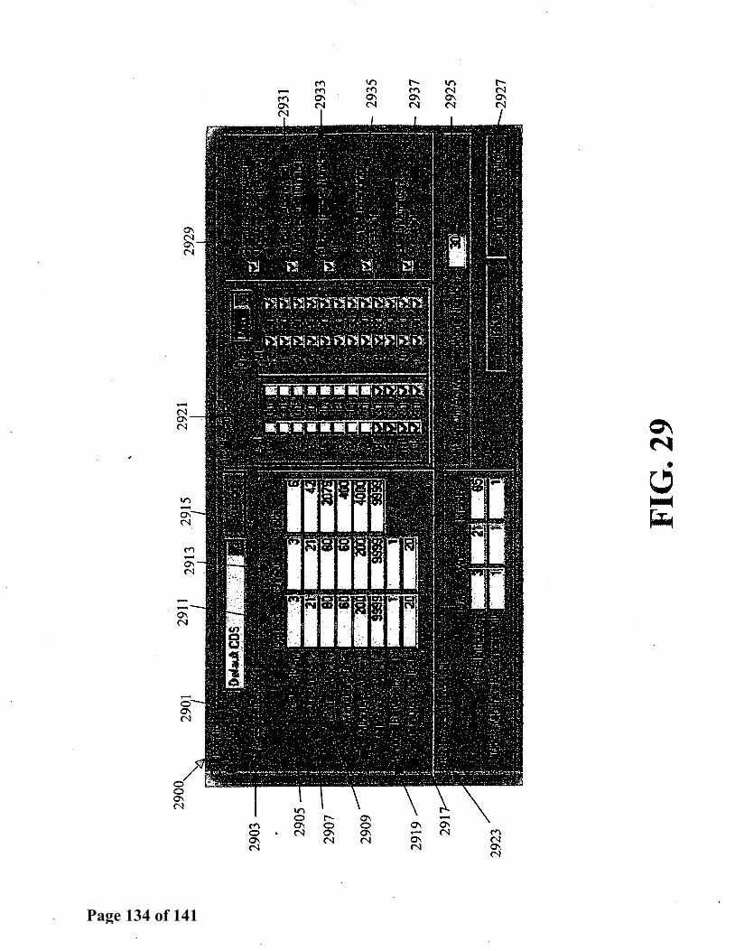
2903
2919
2923
FIG
. 29
2933
2935
. 29
37
2925
2927
Page 134 of 141

0\ ..... 0 M
i 0 II") 1:' 0\ ..... M ....... 0 0 0 0 0 ..... 0 1:' M 0 0 0 M 0 fl) .....
M M M M 0 0 M 0 0 M
Page 135 of 141
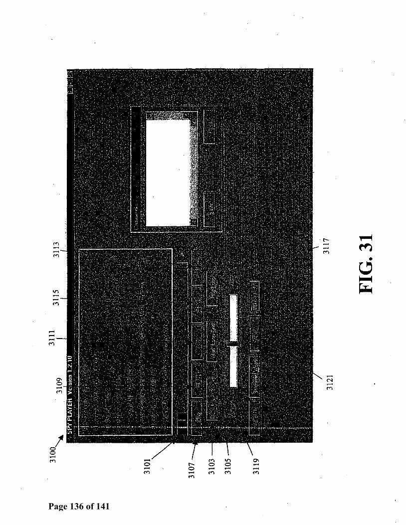
---C""'l
...... 0 ...... C""'l
('. 0 -C""'l
-C""'l
r:--...... M
-N ........ C""'l
Page 136 of 141

3200
32
03
0909
0111
T
IST
IR
0909
0222
T
EST
IHG
-TIS
T
0909
0333
T
IS T
ill
DO
UG
09
0904
44
FJlA
lJKLI
H
!I' R
ID
Q
0999
0101
PH
ILLI
PS
DU
FF
B.
0999
0102
U
ILLJ
OIU
> BU
CK
0999
0103
CO
OK
AVAL
OS
Vlll
.U
0999
0104
ST
OV
ALL
LO
U G
lWI.A
.H
0999
0105
L.
AH
Hm
TG
L
• . 0
9990
106
FIG
. 32
Page 137 of 141

11
/10
/ZO
OO
09
:1Z
:ZZ
·o
9o
9o
1l1
1
1/1
0/2
oo
o o
9 =
18
: zg
. o
9o'9
olll
11
/13
/20
00
09
:39
:02
.
09
09
0l;
l1
1JJ
i3/Z
OO
O 0
8: 4
2:
49
·
09.0
90Z
ZZ
ll
ilO
/tO
OO
. 08
:57
:35
··.
09
09
0Z
ZZ
1
1/1
3/Z
OO
O 0
8:5
4:5
0
09
09
0Z
ZZ
1
1/1
3/Z
OO
O 0
9:0
6:5
9
09
09
0Z
ZZ
1
1/1
3/Z
OO
O 0
9:1
0:1
6
09
09
03
33
1
1/1
0/2
00
0 0
9:2
0:4
7
09
09
03
33
1
1/1
0/Z
OO
O
09
:ZZ
:4?
09
99
01
01
1
2/1
9/Z
OO
O 1
3:4
?:1
8
09
99
01
01
1
2/1
9/Z
OO
O 1
4:3
4:0
5
09
99
01
01
lZ
/19
/ZO
OO
1
4:3
8:2
1
09
99
01
02
1
2/1
9/Z
OO
O 1
5:4
3:0
4
09
99
01
02
1
2/2
0/2
00
0 1
2:4
7:5
8
09
99
01
02
0
1/0
Z/2
00
1 1
3:1
6:1
3
09
99
01
09
1
2/1
9/2
00
0 1
5:2
8:5
0
09
99
01
10
1
Z/1
9/Z
OO
O 1
5:4
?:0
4
11
23
44
53
1
1/0
9/2
00
0 1
5:3
8:3
4
11
/09
/20
00
15
:44
:19
1
1/1
0/Z
OO
O 1
1:5
8:1
2
9?2
80
83
38
2
0:0
0
CAM
P 1
-1
9?2
90
93
39
2
0:1
?
CAM
P 1
-K
9?2
80
83
38
2
0:0
0
CA
HP
1-i
97
28
08
33
13
1
:41
CA
MP
1-B
9
72
80
83
38
2
0:0
0
CAM
P 1
-1
97
28
08
33
82
1
:59
CA
MP
1-1
9
72
80
83
38
2
0:3
5
CAM
P 1
-1
97
28
08
33
82
0
: O
O·•C
AM
P 1
-i
97
28
08
33
82
0
:13
CA
MP
1-1
9
72
80
83
38
2
0:0
0
CAM
P 1
-i
97
28
08
33
82
0
:00
CA
MP
1-1
9
72
80
83
3·8
2
0:
OS
CAM
P 1
-B
40
73
33
70
00
0
:05
CA
MP
l-1
4
07
33
37
00
0
0:0
0
CAM
P 1
-B
40
73
33
70
00
0
:05
CA
MP
1-1
2
14
34
00
65
0
O:Z
l C
AH
P 1
-1
01
15
72
24
12
43
8
0:0
0
CAM
P 1
-1
97
28
08
33
07
0
:00
CA
MP
1-1
9
72
80
83
30
7
0:0
0
CAM
P l-
1
FIG
. 33
Page 138 of 141

Page 139 of 141

3500~
3509
35
11
3503
~
3505
35
13
rrec
tion
al F
a,il
it¥
Acc
ount
Tel
epho
ne tl
.lum
er U
st
TSJ
I
3517
.Pa;
e 1
a£'1
I /3
519
~PM.Nau
3507
__
____
, CD
JIIJc
t D
irec
t R
ec:o
rd
Allo
w
.Ca
W P
uVJ.
ucu.
tce
Dai
a.C
ium
cea
2026
1620
40
YES
Y
ES
YES
y~
EN
GL
lSH
12
Jl51
20J0
97
7.M
2875
4 NO
Y
ES
YES
Y
ES
EN
GL
lSH
12
Jl51.
2000
91
25J3
52.s2
Y
ES
YES
Y
ES
/ Y
ES
EN
GL
lSH
12
11SI
2000
97
2456
S2!D
Y
ES
YES
Y
ES
YES
E
NG
LlS
H
1211
5120
00
2146
4620
00
NO
YES
NO
Y
ES
ENG
LISH
12
1151
2000
21
4396
S78?
Y
ES
YES
Y
ES
YES
E
NG
USH
12
1151
2000
21
4523
64ei
3 Y
ES
YES
Y
ES
YES
E
NG
USH
12
Jl5f
2000
21
4623
3354
Y
ES
YES
Y
ES
YES
E
NG
LlS
H
12J1
7120
00
2146
8155
44
NO
YES
Y
ES
YES
E
NG
LlS
H
l:;n
/200
0 21
4365
2l!B
Y
ES
YES
Y
ES
NO
EN
GU
)H
1217
1200
0
Nun
ber a
f Tel
epho
ne N
unbe
rs fa
Inm
ate:
10
~55264152
Fac..
TS
2 lD
ma1
a N
ama
Will
iam
s M
&tlw
w
3521
FIG
. 35
Page 140 of 141

r
~··~ ....
111b
• 11
1 "-...
_
____
:_LH
+-----
----
---.
~~MS
(w A
N)-
----
----
--1
/
\ \
Aud
to
117
----
+
Rec
orde
r 1
I \
,
Ele
ctro
nic
115 ~Serial
I-I S
wit
chbo
ard
\
• D
evic
e Se
rial
C
entr
al
105b
Site
Ser
ver
___.
1 05
'--------r----------'
~103
.___ _
__
____.
J.---~-~1-0
2-. -~~__
.J._+-~-
102-----
.IJ:.;::
:=:::::=
-=:=:;-J
! 13
:1 B
iom
etri
c l R
F R
ecei
ver
Sens~ng
/ D
evic
e 10
9 10
7 10
8
FIG
. 36
Adm
in.
~120
Wor
ksta
tion
Sha
dow
W
orks
tati
on
Inve
stig
ativ
e W
orks
tati
on
Com
mis
sary
~123
~125
~
121
Page 141 of 141