page 1 of 76 - aerotech fans · ‘c’ pulley manual 37 ‘d’ coupling ... b) cover and seal all...
TRANSCRIPT

Page 1 of 76
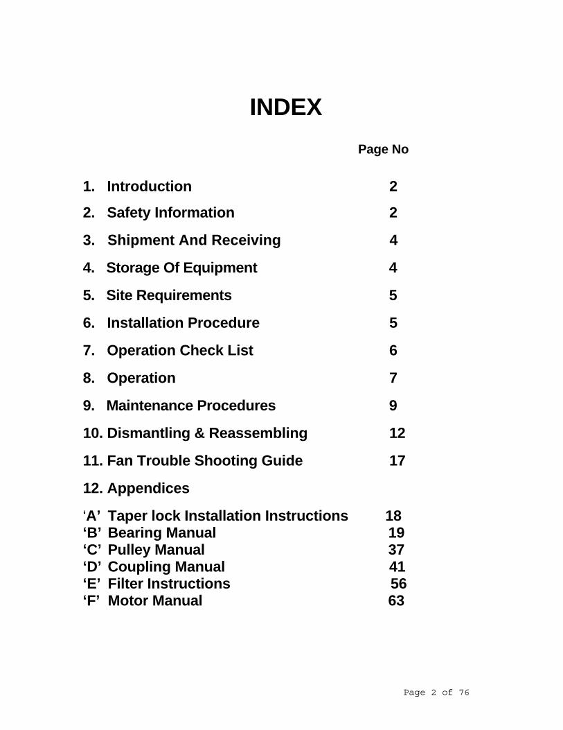
INDEX Page No
1. Introduction 2
2. Safety Information 2
3. Shipment And Receiving 4
4. Storage Of Equipment 4 5. Site Requirements 5
6. Installation Procedure 5
7. Operation Check List 6 8. Operation 7
9. Maintenance Procedures 9
10. Dismantling & Reassembling 12 11. Fan Trouble Shooting Guide 17 12. Appendices ‘A’ Taper lock Installation Instructions 18 ‘B’ Bearing Manual 19 ‘C’ Pulley Manual 37 ‘D’ Coupling Manual 41 ‘E’ Filter Instructions 56 ‘F’ Motor Manual 63
Page 2 of 76

1. INTRODUCTION
This operating manual is intended to assist the end user with basic installation and operation of the fan unit. Process, interfacing and system control equipment is supplied by others, however, be sure to follow all instructions carefully and pay special attention to safety procedures.
HAZARDS/WARNING/SIGNS USED Important information throughout this manual is shown as per example below
A box around the text to group the information to raise the reader’s awareness to the critical information
Warning Take care never to leave objects inside the fan (damage to the impeller may result).
2. SAFETY INFORMATION
THE FOLLOWING SAFETY PRECAUTIONS MUST ALWAYS BE OBSERVED
It is the responsibility of the purchaser to ensure that the installation is handled by qualified personnel experienced in installing this type of equipment. • Maximum operating temperature and speed for which the fan equipment was designed must not
be exceeded. Maximum operating limits must be obtained from Aerotech Fans in writing. • No modifications on the fan equipment is allowed without approval from Aerotech Fans. • Do not start the fan while fan impeller is rotating backwards • Ensure all protective guards are fitted in place during operation. • Access doors on the fan must never be opened during operation of the fan. • Ensure during maintenance that all equipment has been completely isolated from the power
supply. • Remove all loose materials from inside of fan housing and ductwork prior to start up. • Do not clean moving parts when fan is in operation. Ensure that the fan cannot be switched on
accidentally. Isolate fan from power supply. ELECTRICAL CONNECTION The fan must never be connected to the electrical network without including one or more circuit breaking devices enabling human intervention for examination or maintenance to be carried out safely.
In the same way, electrical protection must be provided for the motor to prevent overloading or two-phase operation in the event of an incident occurring. Isolator switches, differential circuit-breakers, heat relays, fuses (etc..) should be used to achieve this.
In all cases use adequately sized power cables having an external dimension compatible with the size of the motor terminal box glands.
Page 3 of 76

Depending on the network voltage, consult the diagram inside the motor terminal box before deciding on the required wiring position of the connecting strips.
3. SHIPMENT AND RECEIVING Before leaving our factory this fan was carefully inspected and passed for workmanship and
dimensional accuracy. On arrival at site, each item should be inspected for any shortages or damage that may have occurred during transit. Any shortages or damage must be noted by the purchaser on the delivery receipt and reported to the carrier and Aerotech Fans. In the event of any such damage, no rework should be done without our written approval.
HANDLING All fans must be handled by a trained personnel and must follow safe handling practices. Verify the
lifting load of the fan and use suitable handling equipment to avoid any serious injury. Some fans may be provided with lifting lugs or holes to facilitate lifting. Use padded chains, cables or straps to protect the fan and fan coating from getting damaged. Do not sling lifting straps to the fan inlet or outlet, fan shaft, impeller or motor. The eyelet on the motor should not be used for lifting the fan.
For centrifugal fans, attach lifting straps to lifting lugs and or structural base members. For axial flow fans, attach lifting straps around the fan housing. The fan impeller and shaft assembly should not be lifted by any of the impeller components. It should
be lifted using spreader bars with straps attached to the shaft on either side of the impeller, as close as possible to the wheel. Impellers shipped separately can be lifted by slings running through the blade section and around the hub. Do not roll the impeller on the floor, this could affect the balance of the impeller.
Warranty claims will not be accepted for any damage caused by improper transport or handling.
4. STORAGE OF EQUIPMENT SHORT TERM STORAGE Store the fan in a covered area and protect the bearings from moisture. LONG TERM STORAGE Long-term storage prior to installation requires the following attention:
a) Coat the shaft with an easily removable rust preventative. b) Cover and seal all bearings, components and ancillaries including motor etc. to
prevent entrance of contaminants and moisture. c) Block the wheel to prevent any unscheduled rotation. d) It is important that the wheel be rotated at least once a month to circulate lubricant to
the bearings. e) The impeller should be left 1800 from that of the previous month to prevent the
impeller assembly to take up a set position on the bearings f) Do not allow material of any kind to be stored on the fan.
FOR EXTENDED STORAGE / SHUT DOWN Units that have been installed, but not operated for several months, should either have
ductwork disconnected or the duct openings covered. All drains, pipe connections and conduit must be covered with plastic caps or tape. Openings in the fan housing or unit
Page 4 of 76

casing should be covered and sealed to keep out dust, dirt and moisture. Check that all doors are closed.
Motor storage per the manufacturer’s instructions, should include care in keeping motor
dry (space heater should be used if necessary).
5. SITE REQUIREMENTS DUCT CONNECTIONS Ductwork should be attached to the fan with flexible connections wherever possible to reduce vibration and must be independently supported. Connecting ductwork directly to the fan may distort the fan components causing vibration and contact between moving parts.
This is critical where temperatures, either by the gas being handled or the surrounding ambient air causes the ductwork to expand on contract. As a general rule, flexible connections are required on all fans operating above 1200 C and for fans mounted on anti-vibration mounts. When fitting the flexible connection ensure that it is not forced onto the fan. If it does not fit exactly, then the adjoining ductwork must be moved or the expansion joint modified so that it does, or undue vibration of the fan and/or ductwork may result. SUPPORT STRUCTURE
A correctly designed concrete base is the best means for installing floor mounted fans. Ensure that the concrete base extends at least 150mm beyond the base of the fan. The weight of the concrete base should be at least 2 to 3 times the weight of the fan assembly, including the motor. The fan should be securely fastened to the base using anchor bolts or expansion fasteners for less demanding applications. Shim and grout as required to level the fan.
Steel platforms can be used for elevated applications. Steel platforms must be adequately braced in
all directions to prevent side sway. Axial flow fans and inline centrifugal fans can be duct mounted provided the supporting duct is
structurally adequate. Roof units must be mounted on top of pre-prepared curb. RESONANCE – Extreme care should be taken to ensure that the natural frequency of the fan
support structure differs significantly ( at least 30% ) from the rotating speed of the fan to avoid resonance. Resonance will cause structural failure.
6. INSTALLATION PROCEDURE MOUNTING ON CONCRETE Ensure foundations are level and conform to the foundation plan on the arrangement drawing. Set the fan unit into position on to its support and bolt in place. If rubber mounts are used , jack up the fan and position the rubber mounts onto their foundations under the fan mounting feet. Lower the fan unit base onto the rubber mounts. Level and shim if required and bolt into position, ensuring that it is level. Make all necessary duct connections If they cannot be moved to make exact connection they must be modified to suit.
Page 5 of 76

It is a good practice to provide access doors in the ductwork adjacent to the fan inlet and outlet to facilitate fan inspection and maintenance.
7. OPERATION CHECK LIST Before undertaking any checks on the fan, ensure that electrical power is isolated. Check electrical wiring to motor. All motors should be connected as shown on motor nameplate. Be sure power supply (voltage, frequency and current carrying capacity of wires) is in accordance with the motor nameplate. Always check to make sure motor bearings are lubricated.
Refer Appendix E Motor Manual Check inlet cone / wheel overlap Check safety guards are all securely fastened to prevent rubbing Check all fastener tightness in case they have come loose during shipment or installation. All securing bolts for motor, bearing assemblies, impeller, foundations, guards and connecting
ductwork must be tight. Check pulley alignment for belt driven fans. Check belt tension. Belts tend to stretch after a few
days of operation. Recheck belt tension.
Refer Appendix C Pulley Manual Check flexible couplings on coupling driven fans.
Refer Appendix D Coupling Manual
Check bearing alignment and make certain they are properly locked to the shaft and lubricated. Do not over lubricate
Refer Appendix B Bearing Manual Touch up all paint work where required. Access doors should be tight and sealed
Turn the rotating section by hand to ensure that the impeller turns freely and does not strike or bind the fan housing or inlet bell. Remove all foreign material such as anti-brinelling locks from the fan and motor shaft.
Discharge damper or variable inlet vanes (if provided) - close vanes or damper during starting periods to reduce power use. The fan is now ready for commissioning / operation.
Page 6 of 76

8. OPERATION STARTING FOR THE FIRST TIME
If the fan is run on cold gas initially then measures should be taken, eg. restriction of flow through dampers, etc., to ensure that the motor power limit is not exceeded.
Turn the power just long enough (bump) to start the impeller rotating. Check impeller rotation to
agree with rotational arrow. Check for unusual noises, rubbing or vibration. Correct any problems after electrical power is isolated.
If no problems are experienced fan may now be brought up to full speed. Check vibration and bearing temperature for normal conditions.
NORMAL STARTS Apply power to the main drive and bring fan to full speed or to required duty point. If the fan is run on cold gas initially then measures should be taken, eg. restriction of flow through dampers, etc., to ensure that the motor power limit is not exceeded. STOPPING THE FAN Please note that the impeller may continue rotating several minutes after stopping the motor. Make sure that the fan is at a complete stand still before attempting to service it. Fan impeller must be locked (wedged) before attempting any internal access or maintenance.
Warning Check fan impeller is stopped before opening Fan Casing for Maintenance
Warning Check Wedge & any tools and debris is removed before closing Fan Casing. HIGH TEMPERATURE EMERGENCY SHUTDOWN
For high temperature fans operating above 1500 C, the fan should only be stopped when the gas temperature drops below 1500 C. If power failure occurs, the fan should be rotated by other auxiliary means continuously until the gas temperature decreases to 1500 C or lower. Failure to do this may distort the fan shaft permanently which can cause severe vibration. For large fans, an auxiliary drive (turning gear) can be used to run the fan slowly (approximately 50 RPM) during shutdowns.
INITIAL RUNNING OF BEARINGS On initial start-up, listen to the bearing for abnormal noises and monitor the temperature rise. The
grease used is suitable for temperatures up to 100oC and bearing temperatures from 30oC to 50oC above ambient may be considered normal. If a rapid temperature rise is encountered, stop fan and remove some of the grease from the bearing and try again. It cannot be emphasised that the most common cause of rapid temperature rise on start-up of fans is excessive greasing of bearings.
If high temperature is still encountered, it is sometimes quite successful to just UN-tighten the bearing cap bolts about a quarter of a turn and re-tighten whilst the fan is running. (This can relieve minor misalignment of the outer track to housing when it was initially tightened).
VIBRATION
Page 7 of 76

A fan running in an unbalanced condition can lead to problems such as, bearing damage, weakening the motor supports, loosening of ducting and surrounding equipment, springing the motor shaft and possibly damaging the impeller itself.
The most common causes of vibration are wear, dirt build up on blades or hub, bent shaft, worn
bearings and misalignment of components. Vibration analysers can be used to measure the level of fan vibration. The vibration velocity is measured as “Root Mean Squared” or RMS. The table below outlines acceptable limits for various situations. The fan should not be operated if its vibration velocity is in the ”Not Permissible” area.
Category 1 Category 2 Category 3 Category 4
0.18 < mm/s = 0.71 Good
0.71 < mm/s = 1.12
1.12 < mm/s = 1.8
1.8 < mm/s = 2.8
2.8 < mm/s = 4.5
4.5 < mm/s = 7.1
7.1 < mm/s = 11.2
11.2 < mm/s = 18.0
18.0 < mm/s = 71 Not Permissible
Mounting Drive 600 < rpm = 1800 1800 < rpm = 12000
Rigid Direct 1 2
Rigid Belt or Coupling 2 3
On anti-vibration mounts Direct 2 3
On anti-vibration mounts Belt or Coupling 3 4
Fan Speed - rpmFan Condition
Fan Mounting ClassificationVelocity Range (r.m.s.) mm/s
Fan Mounting Category
Not Permissible
Satisfactory
Satisfactory
SatisfactoryJust Tolerable
Just Tolerable
Just TolerableNot Permissible
Not Permissible
GoodGood
GoodSatisfactory
Just Tolerable
If the impeller balance requires adjustment, it is preferable to use weights bolted to the impeller, but if electrically welded balance weights are used, it is essential to earth the impeller immediately adjacent to the weld area and not the fan casing. Failure to adopt this procedure may result in damage to bearings due to the passage of the welding current to earth. VEE DRIVE It is important that the correct tension be maintained on the belts at all times, if power is to be transmitted as efficiently as possible, over the life of the belts. The consequences of an under tensioned drive are excessive belt flap, slippage and overheating of the belts, premature belt wear and even belt breakage. On the other hand, an over tensioned drive can result in a premature bearing or shaft failure or belt breakage.
Page 8 of 76

After running for the first hour, the belts are to be re-tensioned to the correct value and after a further few hours of running, the belts are to be re-tensioned again. This procedure is necessary to take up the initial stretch that occurs with new belts and after this stretch has been taken up; the drive should perform satisfactorily provided that periodic adjustments to the belt tension are maintained. FUNCTIONAL CHECKS
During this initial commissioning period and the first week of operation, checks should be made of bearing temperatures, vibration levels and motor winding temperatures.
After operation for the first week, the fan should be well settled in its operation.
9. MAINTENANCE PROCEDURES MAINTENANCE REQUIREMENTS Proper care and maintenance is indispensable in the successful operation of any fan. The amount of maintenance depends upon the kind of operation and care given, as well as the duty the fan will perform and how essential a part it plays in the functioning of other equipment in the plant. Since this is precise engineering equipment, the following instruction should be closely adhered to as any negligence could lead to extensive damage to the unit. PERIODIC INSPECTION The fan will require periodic inspection and records should be kept of conditions, such as the amount of wear, balance, lubrication and paintwork. When the fan is ‘shut down’, ensure that the electrical power is isolated. Check and clean all components. Special attention should be paid to parts in the airstream, especially the impellers since build up on these sections could adversely affect balance and bearing life. Check all parts for wear and alignment repair or replace as necessary. STATIC PARTS
If possible disconnect the fan from the ductwork. Then proceed as follows.: Carefully clean the inner plates of the casing, the inlet cone and (if possible) the upstream and
downstream ducts. Clean the impeller and then refit the inlet cone. Reconnect the ductwork where applicable. Do not leave
any objects inside the fan, this would seriously damage the impeller. Finally, clean the outside of the fan.
Warning Take care never to leave objects inside the fan (Damage to the impeller may result).
Warning Check fan impeller is stopped before opening Fan Casing for Maintenance.
Warning Check any tools and debris is removed before closing Fan Casing
IMPELLER An inspection door on the casing allows periodic inspection of the impeller. Inspect the fan rotor on a regular basis. The rotor is subjected to stresses from centrifugal force and vibration. Remove any traces of build up which could lead to significant and dangerous imbalance of the impeller. Check the condition of welds. Make sure there is no trace of corrosion or rubbing. Note If cracking corrosion or wear is starting, note the position and the dimension of the
defects and repair as required. Then have the impeller balanced in situ.
Page 9 of 76

METHOD OF ADJUSTING BLADE PITCH ON TITAN AXIAL FLOW FAN IMPELLERS The pitch angle on the axial flow fan can be altered without requiring fan removal from the motor shaft. Ensure power supply has been disconnected. The instrument used to adjust pitch angle is a simple protractor with a pendulum and a degree scale on the bottom edge. The protector is positioned across the chord of the fan blade such that, when held vertically, the pendulum pointer is allowed to hang down freely indicating a particular angle on the degree scale. The position of the protractor on the fan blade is indicated by a small triangle cast into the top surface of the blade approximately 200mm from the fan hub. NOTE: The pitch is not read at the blade tip. The protractor should be laid on the blade at the triangle mark so that its face is perpendicular to the blade axis. The blades themselves can be rotated in the hub by loosening all the blade retaining bolts. The blades can be moved in small increments by gently tapping with a rubber mallet near the blade boss. When all the blades in the hub have been adjusted, the bolts should be re-tightened and the pitch angles re-checked. These steps will ensure trouble free operation. PULLEYS/DRIVE BELTS Remove the drive belts and proceed as follows: Carefully clean the drive belts on all sides and check for signs of wear. Carefully clean the pulleys, paying particular attention to the grooves. Check pulley alignment and correct any defects which may come to light. Check belt tension and correct where necessary
Warning If belt tension has to be corrected it is essential to use the method described in Section 9 Vendor Manual Fenner Manual
Clean the inside surfaces and the ventilation openings of the belt guard and its cover Refit the drive guard cover, making sure to replace all the screws.
Important Do not use any solvent which may damage the belts during these cleaning operations.
In case of asymmetrical wear on the belts sides, or if one of the belts shows signs of damage (wear, aging, start of splitting etc..), change the belt set completely.
BEARING HOUSINGS For grease lubricated bearings: Remove the shaft guard Remove the excess grease which accumulates at the grease outlet hole (at the bottom of the bearing housing) Clean the grease nipples Clean the outside of the bearing housing Remove their caps. Remove the used grease Clean the inside of the bearing housing and the bearings and inspect visually.
Page 10 of 76

Warning A polluted bearing will have a much shorter life span and could even
deteriorate quickly. It is therefore important to take particular care and to use clean surroundings and clean materials for these operations (rags brushes etc..)
DISCHARGE DAMPER / VARIABLE INLET VANES The Discharge damper / variable inlet vanes require periodic inspection. Check all linkages, bolted connections, etc. remain properly secured. Also check moveable joints remain free. If signs of wear are evident, repair or replace as required. Re lube damper bearings if required. ELECTRIC MOTOR The three basic rules of motor maintenance are: keep it clean, dry and properly lubricated. Proceed as follows after disconnecting the power: Clean outside paying particular attention to the ventilation openings. Visually inspect the power supply cable and its cable gland. Remove the terminal box cover. Check the connections of the power supply cable on the terminal block. Tighten the cables if necessary. Carefully close the terminal box replacing all seals.
Note Refer to Appendix C Motor Manual for detailed maintenance instructions.
LUBRICATION DETAILS Fan Shaft Bearings The most common grease type is Shell Alvania R3 grease or equivalent.
Note: It is preferable to re-lubricate the bearings while the shaft is rotating, as this assists in the eviction of any degenerated grease and its ultimate discharge from the bearings.
Bearings For Damper Or Variable Inlet Vanes Relubricate every 6 months with Shell Alvania R3 Lithium base grease or equivalent Change grease every 12 months. Electric Motor Lubricate in accordance with Motor Manufacturer's instructions.
Refer to Appendix C Motor Manual
Page 11 of 76

10. DISMANTLING & REASSEMBLING Before attempting any maintenance on the fan or other ancillary items, ensure that all items are isolated from the main power supply.
BELT REMOVAL Remove belt guard
Undo motor fixing bolts and move motor so that belts become slack enough to be removed from the pulley. Do not use a lever to force the belt out of the pulley groove. This could permanently lengthen and damage the belt.
PULLEY REMOVAL
Take out the two (or three for larger pulleys) screws tightening the taperlock bush to the pulley. Insert one of these screws into the hole for extracting the bush. Tighten this screw until the bush is released. Slide the pulley and bush out of the shaft. i IMPELLER REMOVAL
(a) Unbolt and remove all duct work from inlet side of fan. (b) Remove bolts connecting inlet cone assembly to housing.
(c) Remove inlet cone away from housing assembly.
(d) Remove taper lock bush from end of shaft centre
Refer Appendix A Taperlock instructions
(e) For impellers with straight bores, Two tapped holes on the impeller hub (keeper plate)
can be used for removing the impeller with a suitable puller.
(f) Then withdraw impeller away from shaft and casing. IMPELLER REPLACEMENT Generally the impeller will be assembled in the reverse order to which it was removed. However, the following points are to be adhered to:
a) Before fitting impeller to shaft, clean the motor or fan shaft and impeller bore of dirt or burrs. Burrs can be removed with emery cloth.
b) For impellers with straight bores, impellers usually come supplied with two securing bolts,
one over the keyway and the other at 900. Ensure that securing bolts do not protrude into the impeller bore
Page 12 of 76

c) When assembling the impeller onto the shaft be sure to lubricate the shaft before fitting. Align match marks.
d) Ensure the correct gap between inlet and impeller back plate is maintained before
tightening the taper lock or securing bolts. BEARING REMOVAL for Belt or Coupling Driven Fans
For changing bearing only, the impeller need not be removed from the shaft. However, ensure that the shaft is straight and in good order. The impeller weight should be supported before loosening the bearings. Remove bearing to fan shaft fastener and bearing to fan pedestal fastener. Ensure that the shaft is clean and smooth to facilitate the bearings to slide out at the end of the shaft.
SHAFT AND BEARING REMOVAL & REPLACEMENT for Belt or Coupling Driven Fans Remove all guards. Remove drive belts and fan pulley for belt driven fans. For coupling driven fans, remove shaft guard and coupling guard then remove coupling driving element. Remove shaft seal bolts. Remove the fan impeller from the shaft. Note the length of the keyway at each end of the shaft so that the new shaft can be mounted in the proper orientation. Remove bearing bolts from support pedestal. Withdraw shaft, shaft seal and bearings complete from fan assembly. Use heavy canvas to protect the shaft. Remove the bearing caps then remove bearing races from the shaft. Note : Mark location of races on shaft . Bearings are to be assembled onto the shaft with the adapter nuts of both bearings facing the fan housing and lightly tightened to allow for adjustment. The bearings are to be assembled in clean surroundings and no dirt is to be permitted into the bearings
Tighten bearings to fan pedestal. Do not tighten the bearings to fan shaft. Mount impeller to new shaft but do not tighten hub to shaft in case impeller need to be adjusted axially. Reinstall fan inlet and adjust inlet/impeller clearance. Fit belt drive pulley to shaft, but do not tighten. Align with motor pulley using straight edge. Once all alignments and adjustments are complete, tighten impeller to shaft and pulley to shaft. Tighten only one bearing to shaft. Apart from the second bearing to shaft not being tightened, all other fasteners and connections can be secured. Check all safety aspects of fan operation. Unlock power source and run the fan for a few seconds. Once the impeller comes to a complete stop, tighten the second bearing to shaft. Restart fan check vibration levels before running the fan continuously.
Page 13 of 76

TYPICAL BEARING ASSEMBLY PROCEDURE Two types of bearings are generally used by Aerotech Fans. They are: 1. Ball Bearing 2. Spherical Roller Bearing
Ball Bearings are self aligning bearings and basically do not present aligning problems. Common failure arises from mounting bolts becoming loose and allowing the fan shaft to turn within the bearing. Spherical Roller Bearings are also self aligning and good alignment allows the bearing to operate without getting over heated. Good alignment is very critical for bearings operating at high speeds. Improper installation is a common cause for bearing failure. Premature failure can be caused by removing too much clearance from the bearing and not removing enough clearance results in the fan shaft turning within the bearing. 1. Check that the bearing housing seats on fan pedestal are flat. 2. Check the shaft is not worn or damaged where the adaptors are to be fitted (wear
on shaft in this area would indicate that previously fitted adaptors have been turning on the shaft).
3. Before fitting bearings, measure the internal clearance of the bearings on the
bench after cleaning out preservative oil. 4. Clean adaptors. 5. Assemble seal carriers, ‘V’ ring, metallic rotating seals, adaptor sleeve, race,
locking washer and locknut to the shaft 6. Tighten the adaptor nut enough to halve the internal clearance. The bearing
should always be rotated a few times before each measurement is made. 7. Properly pack grease into the bearings and fit into housings. The fixed bearing
race is to be positioned in the bearing housing so that the fixing ring can be inserted into the bearing housing, on both sides of the race. The floating bearing race is to be positioned central in the bearing housing.
8. Remove bearing cap and bend tag of lock washer to sufficiently engage in the lock
nut, but not hammered down flat so that it will be difficult to pry open in a subsequent bearing refit.
9. Pack the bearing housing with grease. It is only necessary to pack about 50% of the housing with grease. Excessive greasing will cause an immediate high temperature of the bearing on start-up.
10. Re-tighten bearings caps, rotating shaft if possible whilst nipping up the bearing caps tightly
Page 14 of 76

BELT DRIVE INSTALLATION & MAINTENANCE 1. Fit the fan & motor pulleys to their shaft 2. Tighten the taper lock bush grub screws of the fan shaft pulley. Using a straight
edge, align the motor pulley and when satisfied that the positioning of the motor pulley is correct, tighten the taper lock bush grub screws.
3. Loosen the motor holding down bolts and move the motor so that the belts can be
installed without forcing them over the pulleys. Adjust the drive
Once the drive has been correctly tensioned and run in, check the tension again and readjust if necessary
5. Install the belt guard COUPLING ASSEMBLY & ALIGNMENT Ensure that the faces of the fan (shaft) coupling and motor coupling are parallel using tapered wedge, feeler gauges, dial indicator or laser alignment.
Angular Misalignment Parallel Misalignment
Page 15 of 76
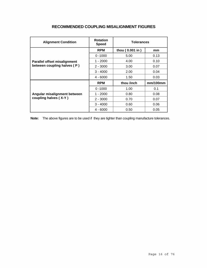
RECOMMENDED COUPLING MISALIGNMENT FIGURES
Alignment Condition Rotation Speed Tolerances
RPM thou ( 0.001 in ) mm 0 -1000 5.00 0.13 1 - 2000 4.00 0.10 2 - 3000 3.00 0.07 3 - 4000 2.00 0.04
Parallel offset misalignment between coupling halves ( P )
4 - 6000 1.50 0.03
RPM thou /inch mm/100mm 0 -1000 1.00 0.1 1 - 2000 0.80 0.08 2 - 3000 0.70 0.07 3 - 4000 0.60 0.06
Angular misalignment between coupling halves ( X-Y )
4 - 6000 0.50 0.05 Note: The above figures are to be used if they are tighter than coupling manufacture tolerances.
Page 16 of 76

11. FAN TROUBLE SHOOTING GUIDE
Symptom Possible Cause
1. Fan will not start
Blown fuses Broken belts Loose Pulleys Impeller touching housing Wrong voltage
2. Excessive noise and vibration
Misalignment of bearings, coupling, wheel or drive Unstable foundation Foreign material in fan causing unbalance Worn bearings Worn coupling Damaged impeller or motor Broken or loose bolts Bent shaft Fan wheel or driver unbalanced Fan delivering more than rated capacity Speed too high or fan rotating in wrong direction
3. Air volume too small
Wrong fan rotation Fan speed too slow Pulley mounted back to front Dampers closed too much Coils and filters dirty Inlet or outlet obstructions Fan too small for application Improperly designed turning vanes Air leaks in system Damaged impeller Wheel mounted backwards on impeller System resistance higher than design
4. Air volume too large
Wrong fan rotation Fan speed too high Pulley mounted back to front Dampers not installed Access door open Fan too large for application Oversized ductwork System resistance lower than design
5. Overload on motor
Speed too high Discharging over capacity due to existing system resistance being lower than original rating. Specific gravity or density of gas above design value. Wrong direction of rotation Bent shaft Poor alignment Wheel wedging or binding on inlet belt Bearings improperly lubricated Motor improperly wired Incorrect motor selection
6. Overheated bearings
Too much grease in bearings Poor alignment Damaged impeller or drive Dirt in bearings Abnormal end thrust Bent shaft Incorrect lubricant
Page 17 of 76
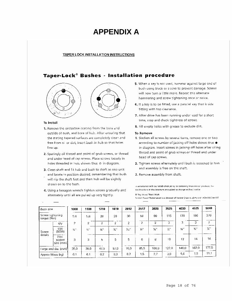
APPENDIX A
Page 18 of 76
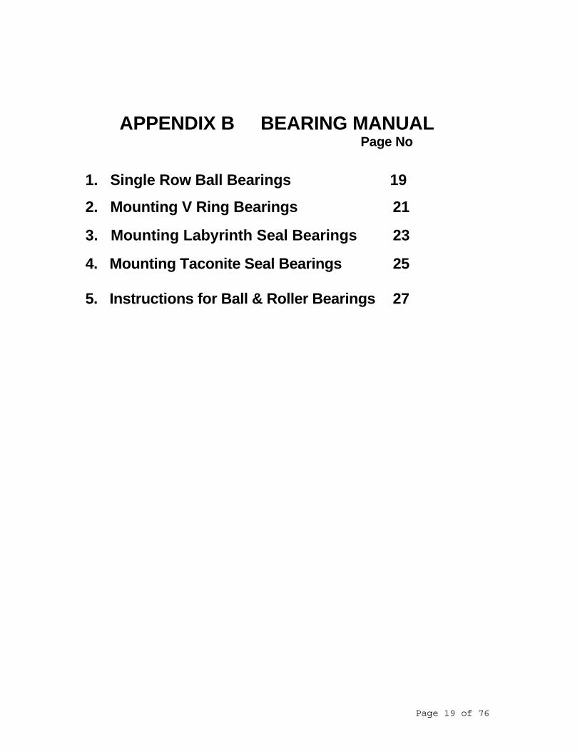
APPENDIX B BEARING MANUAL Page No
1. Single Row Ball Bearings 19
2. Mounting V Ring Bearings 21
3. Mounting Labyrinth Seal Bearings 23
4. Mounting Taconite Seal Bearings 25 5. Instructions for Ball & Roller Bearings 27
Page 19 of 76

Page 20 of 76

Page 21 of 76

Page 22 of 76

Page 23 of 76

Page 24 of 76

Page 25 of 76

Page 26 of 76

Page 27 of 76

Page 28 of 76

Page 29 of 76

Page 30 of 76

Page 31 of 76

Page 32 of 76

Page 33 of 76

Page 34 of 76

Page 35 of 76

Page 36 of 76
APPENDIX C PULLEY MANUAL
Page 37 of 76

Page 38 of 76

Page 39 of 76

Page 40 of 76
APPENDIX B COUPLING MANUAL Page No
1. HRC Couplings 41
2. Fenaflex Tyre Couplings 44
3. Tapered Grid Couplings 48
Page 41 of 76

Page 42 of 76

Page 43 of 76

Page 44 of 76

Page 45 of 76

Page 46 of 76

Page 47 of 76

Page 48 of 76
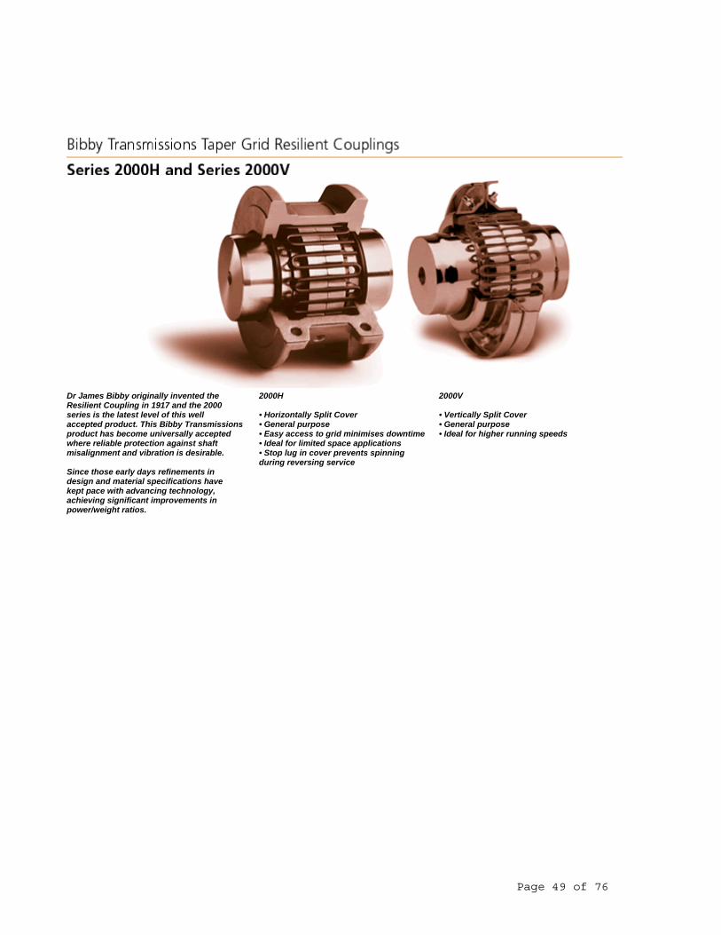
Dr James Bibby originally invented the Resilient Coupling in 1917 and the 2000 series is the latest level of this well accepted product. This Bibby Transmissions product has become universally accepted where reliable protection against shaft misalignment and vibration is desirable. Since those early days refinements in design and material specifications have kept pace with advancing technology, achieving significant improvements in power/weight ratios.
2000H • Horizontally Split Cover • General purpose • Easy access to grid minimises downtime • Ideal for limited space applications • Stop lug in cover prevents spinning during reversing service
2000V • Vertically Split Cover • General purpose • Ideal for higher running speeds
Page 49 of 76

High Performance The Bibby Transmissions Series 2000 Taper Grid Coupling continues that tradition. The tapered grid is made from high tensile alloy steel which is carefully formed to the grid shape before hardening and tempering under controlled conditions. The grid surface is then shot-peened. This process leaves the grid spring with a residually stressed surface layer which is in compression and which impedes the propagation of cracks. Since nearly all fatigue and stress corrosion failures originate at the surface of a part, the layer of compressive stress induced by shot-peening produces a dramatic increase in the working life and fatigue strength of the grid. This technological improvement in manufacturing process coupled with precise monitoring of raw material specification and control of trapezoidal shape, permits Bibby Transmissions to offer state of the art grid springs of high performance and reliability. Scientific Design The hub is precision manufactured from high quality materials, with the hub tooth profile scientifically designed to permit
progressive loading under torsional shock conditions. The combination of tapered grid and precision manufactured hub provides a high performance transmission arrangement which is easily assembled, extremely capable of cushioning shock loads and allowing for compensation for drive misalignments. Long Life Whilst the coupling is designed for long life under arduous conditions, maintenance and taper grid replacement can be performed quickly and easily without the need to move and realign connected equipment. Two cover design options are available in the Bibby Transmissions Series 2000 range of couplings. Both designs have beencarefully engineered to match the qualitystandards of the key components and to provide a shaft coupling which is highlyreliable and easy to install. Recommended Fits between Shafts and Hubs Coupling bore tolerances for sizes up to and including 2090T can be specified to suit a transition fit with the shaft. In
these instances axial restraint of the hub should be provided by set screws. Relative sizes and positions are given in the following table. For sizes above 2090T or where interference fits are preferred for smaller coupling sizes, bore tolerances should provide an interference fit between shaft and hub of 0.0002 to 0.0007mm per mm of diameter
Page 50 of 76

Positive protection against the damaging effects of shock loads, impact loads and vibration. The Series 2000 is torsionally flexible. The circumferential flexibility is progressive due to the curved profile of the grooves - ‘state-of-the-art’ in resilient coupling design.
Accommodating Shaft Misalignment and End-Float The Series 2000 will accommodate combinations of misalignments present at set-up or occurring during machine displacement, settlement etc. Effectiveness of Torsional Damping As the Series 2000 coupling transmits torque, the flexing of the tapered grid spring de-tunes vibrations and cushions shock loads.
This unique charecteristic is due to the torsional flexibility of the coupling being proportionate to the unsuppotred length of each flexible grid rung. since this varies with every variation of torque, a
powerful de-tuning action is produced which continuously alters the natural frequency of the system and prevents a build-up of resonance in the system. The resultant reduction in peak loading protects and extends the life of the transmission equipment. Versatile Design Both 2000H and 2000V couplings feature identical hubs and grid springs, the different cover styles endowing the units with great versatility - one is horizontally split, the other is vertically split. All coupling components are designed to be interchangeable with other taper grid couplings.
The stock coupling can be used vertically or horizontally without modification. Easy Installation and Maintenance The grid springs are easily installed by hand or with a soft mallet. The cover fasteners can be tightened with standard wrenches. Every Bibby Transmissions’ Series 2000 coupling is delivered with detailed installation instructions. Periodic lubrication of the coupling is required and each cover half is supplied with standard plugs which can be easily removed for re-lubrication. Extended lubrication periods and enhanced coupling life can be achieved by using high performance lubricants referred to in the maintenance instructions.
Page 51 of 76

Positive protection against the damaging effects of shock loads, impact loads and vibration. The Series 2000 is torsionally flexible. The circumferential flexibility is progressive due to the curved profile of the grooves - ‘state-of-the-art’ in resilient coupling design.
Accommodating Shaft Misalignment and End-Float The Series 2000 will accommodate combinations of misalignments present at set-up or occurring during machine displacement, settlement etc.
Page 52 of 76

Effectiveness of Torsional Damping As the Series 2000 coupling transmits torque, the flexing of the tapered grid spring de-tunes vibrations and cushions shock loads.
This unique charecteristic is due to the torsional flexibility of the coupling being proportionate to the unsuppotred length of each flexible grid rung. since this varies with every variation of torque, a
powerful de-tuning action is produced which continuously alters the natural frequency of the system and prevents a build-up of resonance in the system. The resultant reduction in peak loading protects and extends the life of the transmission equipment. Versatile Design Both 2000H and 2000V couplings feature identical hubs and grid springs, the different cover styles endowing the units with great versatility - one is horizontally split, the other is vertically split. All coupling components are designed to be interchangeable with other taper grid couplings.
The stock coupling can be used vertically or horizontally without modification. Easy Installation and Maintenance The grid springs are easily installed by hand or with a soft mallet. The cover fasteners can be tightened with standard wrenches. Every Bibby Transmissions’ Series 2000 coupling is delivered with detailed installation instructions. Periodic lubrication of the coupling is required and each cover half is supplied with standard plugs which can be easily removed for re-lubrication. Extended lubrication periods and enhanced coupling life can be achieved by using high performance lubricants referred to in the maintenance instructions.
Page 53 of 76

1) Coupling weight and MR² with no bore. 2) Max bores stated above use rectangular parallel keyways to BS 4235 pt 1 1972 or DIN 6885 sht 1 1969 3) Other couplings available are spacer and
Page 54 of 76
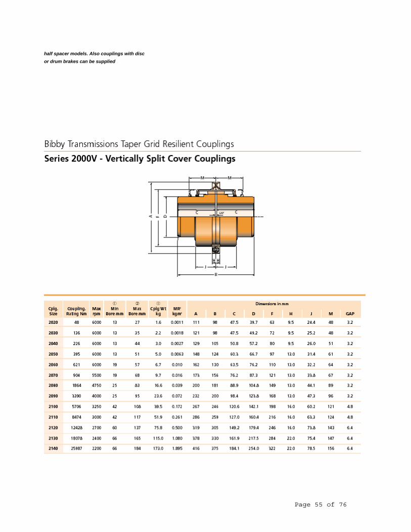
half spacer models. Also couplings with disc or drum brakes can be supplied.
Page 55 of 76

APPENDIX E FILTER INSTRUCTIONS
Page 56 of 76

Page 57 of 76

Page 58 of 76

Page 59 of 76
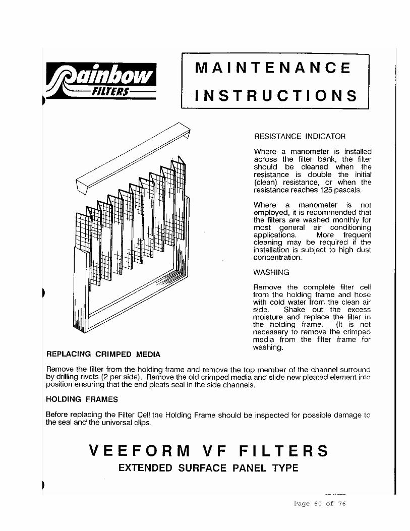
Page 60 of 76

Page 61 of 76

Page 62 of 76
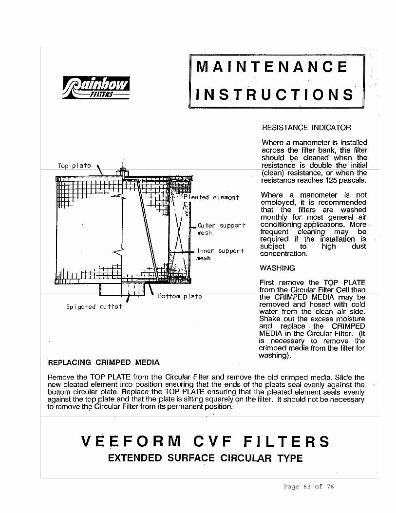
Page 63 of 76
APPENDIX F MOTOR MANUAL Page No
1. Weg Motors 64
2. Teco Motors 71
3. CMG Motors 74
Page 64 of 76

Page 65 of 76

Page 66 of 76

Page 67 of 76

Page 68 of 76
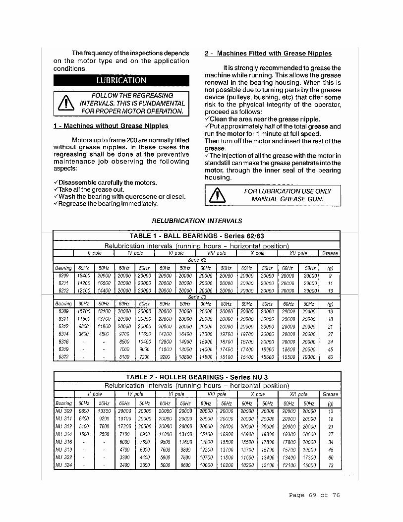
Page 69 of 76

Page 70 of 76

Page 71 of 76

Page 72 of 76

Page 73 of 76

Page 74 of 76

Page 75 of 76

Page 76 of 76