page 19-3 page 19-6 page 19-7 level control relays …
TRANSCRIPT

LEVEL CONTROL RELAYS• For conductive liquids• Single, dual or multivoltage• Emptying or filling functions• Multifunctions• Automatic reset• Modular and plug-in versions.
Page 19-3 Page 19-6
PROBES, ELECTRODES AND ELECTRODEHOLDERS• Single pole• Three pole.
Page 19-7
FLOAT SWITCHES • Versions for grey and dirty water• Versions with PVC and Neoprene cable• Emptying or filling functions.
Page 19-8
START-UP PRIORITY CHANGE RELAYS • 2 outputs• Single or multivoltage• Modular and plug-in versions.

LEVEL CONTROLS 19
Level monitoring for electricallyconductive liquidsModular and plug-in versionsAdjustable 2.5…200kΩ sensitivitySingle and three-pole probesFloat switchesStart-up priority change relays.
SEC. - PAGE
Level monitoring relaysModular version for conductive liquids .............................................................................................................................. 19 - 3Plug-in version for conductive liquids................................................................................................................................. 19 - 5
Probes, electrodes and electrode holders ............................................................................ 19 - 6Float switches .............................................................................................................. 19 - 7Start-up priority change relays
Modular version ................................................................................................................................................................ 19 - 8Plug-in version .................................................................................................................................................................. 19 - 8
Accessories ................................................................................................................. 19 - 9
Dimensions ................................................................................................................. 19 - 10Wiring diagrams ........................................................................................................... 19 - 11Technical characteristics ................................................................................................. 19 - 14
AU
TO
MA
TIO
NA
ND
CO
NT
RO
L

19
19-2
Level controls
Modular version �(2U) �(1U) �(3U) �(3U) �(1U) �(3U) Plug-in version � � � (8 pin) (11 pin) (11 pin) 3 detecting electrodes (MIN, MAX and COM) � � � � �
5 detecting electrodes (MIN1, MAX1, MIN2, MAX2 and COM) �
Sensitivity adjustment 2.5...50kΩ � �
Sensitivity adjustment 2.5...100kΩ � Sensitivity adjustment 2.5...200kΩ �
Fixed sensitivity: 7…8kΩ � �
Adjustable sensitivity full-scale value 25-50-100-200 kΩ �
Separate sensitivity adjustment for MAX probe (foam detection) �
Emptying function and alarms � � � � � �
Filling function and alarms � � �
Emptying function with Extra-MIN and/or Extra-MAX alarm relays �
Filling function with Extra-MIN and/or Extra-MAX alarm relays �
Emptying function with start change control �
Filling function with start change control �
Tank filling, well drawing functions and alarm �
Filling-emptying adjustment selector �
�
Programming selector for 5 different functions �
Motor start-up priority change � Motor start-up priority change with stand-by motor function � �
Page
Description LEVEL CONTROL RELAYS PRIORITY CHANGE RELAYS FOR 2 MOTORS
LVM20 LVM25 LVM30 LVM40 LV1E LV2E LVMP05 LVMP10 CSP2E
19-3 19-4 19-5 19-8
Type of liquid Resistivity kΩcmMilk ~1Whey ~1Fruit juices ~1Vegetable juices ~1Soups ~1Wine ~2.2Beer ~2.2Coffee ~2.2Suds ~18
Type of liquid Resistivity kΩcm Drinking water 5–10 Well water 2–5 River water 2–15 Rainwater 15–25 Sludge 0.5–2 Seawater ~0.03 Salt water ~2.2 Natural/hard water ~5 Chlorinated water ~5 Condensed water ~18
N.B. The resistivity values in the table are purely indicative.
• Purified water• Deionised water• Petrol• Oil• Liquid gases• Paraffin • Ethylene glycol• Paints• Liquids with a high percentage of alcohol
Some permitted liquid substances Liquid substances not permitted

19
19-3Dimensions page 19-10
Wiring diagrams page 19-11
Technical characteristicspage 19-14
Level controlsLevel control relays.Modular version
Operational characteristics– Used with 3 sensing electrodes, MIN, MAX and COM– 2.5…50kΩ adjustable sensitivity– Double insulation between each supply, electrodes and
output relay circuits– Fixed probe signal delay: <1s– Green LED indicator for power on– Red LED indicator for output relay state– Modular DIN 43880 housing (2 modules)– IEC degree of protection: IP40 on front (only when
mounted in housing or electric board with IP40); IP20 on terminals.
Certifications and complianceCertifications obtained: EAC, UL Listed, for USA andCanada (cULus-File E93601), as Auxiliary Devices - Levelcontrol relays.Compliant with standards: IEC/EN 60255-5,IEC/EN 61000-6-2, IEC/EN 61000-6-3, UL508, CSA C22.2 no. 14.
Probes, electrode holders and float switchesUse probes and electrode holders type:SN1/PS31/PS3S/SCM/CGL or similar (see page 19-6).For the choice of float switches see page 19-7.
Order Auxiliary Type of Qty Wt code supply output per voltage contact pack [V] 50/60Hz n° [kg] Emptying function. Automatic reset. LVM20 A024 24VAC 1 C/O (SPDT) 1 0.215 LVM20 A127 110...127VAC 1 C/O (SPDT) 1 0.215 LVM20 A240 220...240VAC 1 C/O (SPDT) 1 0.215 LVM20 A415 380...415VAC 1 C/O (SPDT) 1 0.215
LVM20...
Operational characteristics– Used with 3 sensing electrodes, MIN, MAX and COM– 2.5…50kΩ adjustable sensitivity– Programming selector for emptying or filling function
with fail-safe operation– Double insulation between each supply, electrodes and
output relay circuits– Adjustable probe signal delay: 1...10s or pump start
delay: 0...300s– Green LED indicator for power on– Red LED indicator for output relay state– Modular DIN 43880 housing (3 modules)– IEC degree of protection: IP40 on front (only when
mounted in housing or electric board with IP40); IP20 on terminals.
Certifications and complianceCertifications obtained: EAC, UL Listed, for USA andCanada (cULus-File E93601), as Auxiliary Devices - Levelcontrol relays.Compliant with standards: IEC/EN 60255-5, IEC/EN 61000-6-2, IEC/EN 61000-6-3, UL508, CSA C22.2 n° 14.
Probes, electrode holders and float switchesUse probes and electrode holders type:SN1/PS31/PS3S/SCM/CGL or similar (see page 19-6).For the choice of float switches see page 19-7.
Order Auxiliary Type of Qty Wt code supply output per voltage contact pack [V] 50/60Hz n° [kg] Emptying or filling functions. Automatic reset. LVM30 A240 24/220...240VAC 2 C/O (SPDT) 1 0.315 LVM30 A415 110...127VAC 2 C/O (SPDT) 1 0.315 380...415VAC
Dual-voltage relay
LVM30...
Operational characteristics– Used with 3 sensing electrodes, MIN, MAX and COM– 2.5…100kΩ adjustable sensitivity– Insensitivity to stray electrode-cable capacitance– Programming selector for emptying or filling function
with fail-safe operation– Double insulation between each supply, electrodes and
output relay circuits– Fixed probe signal delay: <1s– Green LED indicator for power on– Red LED indicator for output relay state– Modular DIN 43880 housing (1 module)– IEC degree of protection: IP40 on front (only when
mounted in housing or electric board with IP40); IP20 on terminals.
Certifications and complianceCertifications obtained: EAC, UL Listed, for USA andCanada (cULus-File E93601), as Auxiliary Devices - Levelcontrol relays.Compliant with standards: IEC/EN 60255-5, IEC/EN 61000-6-2, IEC/EN 61000-6-4, UL508, CSA C22.2 n° 14.
Probes, electrode holders and float switchesUse probes and electrode holders type:SN1/PS31/PS3S/SCM/CGL or similar (see page 19-6).For the choice of float switches see page 19-7.
Order Auxiliary Type of Qty Wt code supply output per voltage contact pack [V] n° [kg] Emptying or filling functions. Automatic reset. LVM25 240 24...240VAC/DC 1 C/O (SPDT) 1 0.095
Multi-voltage relay
Single-voltage relay
LVM25 240
LVMKIT25
Order Description Qty Wt code per pack n° [kg] Level control relay LVM25 240 and SN1 electrodes kit. LVMKIT25 Level control relay LVM25 240 1 0.192 and 2 SN1 probes

19
19-4Dimensions page 19-10
Wiring diagrams page 19-12
Technical characteristicspage 19-14
Level controlsLevel control relays.Modular version
Operational characteristics– Use with 5 sensing electrodes, MIN1, MAX1, MIN2,
MAX2 and COM– 2.5…200kΩ adjustable sensitivity– Adjustable sensitivity full-scale value: 25-50-100-200kΩ– Separate sensitivity adjustment of MAX electrodes for
foam detection– Insensitivity to stray electrode-cable capacitance– Programming selector for 5 different functions: • emptying function and alarms (pos. A) • filling function and alarms (pos. B) • emptying function with priority start-up change
control (pos. C) • filling function with priority start-up change
pump (pos. D) • well draining and tank filling and alarms (pos. E)– Double insulation between each supply, electrodes and
output relay circuits– Adjustable probe signal delay: 1...10s– Adjustable pump start delay: 0...30min– Green LED indicator for power on– Red LED indicators for output relay and electrode state– Modular DIN 43880 housing (3 modules)– IEC degree of protection: IP40 on front (only when
mounted in housing or electric board with IP40); IP20 on terminals.
Certifications and complianceCertifications obtained: EAC, UL Listed, for USA andCanada (cULus-File E93601), as Auxiliary Devices - Levelcontrol relays.Compliant with standards: IEC/EN 60255-5, IEC/EN 61000-6-2, IEC/EN 61000-6-3, UL508, CSA C22.2 n° 14.
Probes, electrode holders and float switchesUse probes and electrode holders type:SN1/PS31/PS3S/SCM/CGL or similar (see page 19-6).For the choice of float switches see page 19-7.
Order Auxiliary Type of Qty Weight code supply output per voltage contacts pack [V] 50/60Hz � n° [kg] Emptying or filling functions. Multifunctions. Automatic reset. LVM40 A024 24VAC 1+1NO 1 0.278 LVM40 A127 110...127VAC 1+1NO 1 0.278 LVM40 A240 220...240VAC 1+1NO 1 0.278 LVM40 A415 380...415VAC 1+1NO 1 0.278� Two relay outputs; one with c/o (SPDT) and the other with N/O (SPST).
Single-voltagemultifunction relay
LVM40...
FUNCTIONS
A- Emptying with MIN and/orMAX alarms.
B- Filling with MIN and/or MAXalarms.
EXAMPLE OF EMPTYING OPERATIONTo achieve this type of operation, two electrodes are usedto control the liquid between the fixed limits using MIN1and MAX1 and two alarm levels using MIN2 and MAX2.When one of the alarm electrodes is wet, the alarm relay isde-energised.The alarm can be caused by pump malfunction,insufficient pump delivery capacity, MAX control levelfailure or MIN level electrode shorted. With a proper connection, only the MIN alarm or MAXalarm can be activated or neither of the two can beactivated so the relative output contacts can be used forpump control.COM
MIN 2MIN 1
MAX 1StartStopAlarm
MAX 2Alarm
Tank
C- Emptying with pump prioritychange.
D- Filling with pump prioritychange.
EXAMPLE OF EMPTYING OPERATIONThis operation is obtained by using four electrodespositioned at four different levels and two relay outputs tocontrol two pumps. For example, one can place the fourelectrodes, MIN1, MIN2, MAX1 and MAX2, in increasingorder from the lowest to the highest levels and mustcontrol the tank emptying. Usually the level is controlledbetween the MIN1 and MAX1 levels by starting one of thetwo pumps. This case is different so the pumps can bemaintained at the best efficiency and optimise their wear.When the liquid wets the MAX2 level and because the firstpump is faulty or else a higher delivery capacity is needed,the second stand-by pump is activated to back up the firstpump. When the liquid lowers and no longer wets theMIN2 level, the second pump is stopped and then whenthe MIN1 level is no longer wet, the first pump is stoppedtoo.
Tank
COMMIN 1
MIN 2MAX 1
MAX 2
E- Tank filling and well drawingwith alarm.
EXAMPLE.Two electrodes are used in this operation to control thetank level and another two for the well. One relay is usedto activate the pump while the other for dry running / nowater alarm.When the well liquid wets the MAX2 level and the liquidwets the MIN1 tank level, the tank-filling pump isactivated.When the tank MAX1 level is wet, the pump is stopped.During the tank filling, the pump could stop before theMAX1 level is wet because the well MIN2 level is no longerwet.Should the tank MIN1 level no longer be wet at which thepump should restart but the well MIN2 level is also nolonger wet, then the alarm relay is de-energised.
Tank
Tank
COM
COM
MIN 1
MIN 2
MAX 1
MAX 2
19
19-5Dimensions page 19-10
Wiring diagrams page 19-13
Technical characteristicspage 19-15
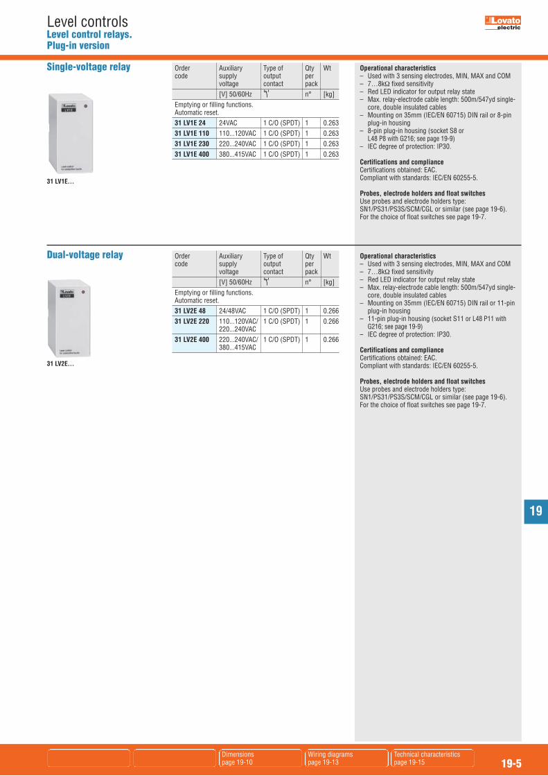
Level controlsLevel control relays.Plug-in version
Operational characteristics– Used with 3 sensing electrodes, MIN, MAX and COM– 7…8kΩ fixed sensitivity– Red LED indicator for output relay state– Max. relay-electrode cable length: 500m/547yd single-
core, double insulated cables– Mounting on 35mm (IEC/EN 60715) DIN rail or 11-pin
plug-in housing– 11-pin plug-in housing (socket S11 or L48 P11 with
G216; see page 19-9)– IEC degree of protection: IP30.
Certifications and complianceCertifications obtained: EAC.Compliant with standards: IEC/EN 60255-5.
Probes, electrode holders and float switchesUse probes and electrode holders type:SN1/PS31/PS3S/SCM/CGL or similar (see page 19-6).For the choice of float switches see page 19-7.
Order Auxiliary Type of Qty Wt code supply output per voltage contact pack [V] 50/60Hz n° [kg] Emptying or filling functions. Automatic reset. 31 LV2E 48 24/48VAC 1 C/O (SPDT) 1 0.266 31 LV2E 220 110...120VAC/ 1 C/O (SPDT) 1 0.266 220...240VAC 31 LV2E 400 220...240VAC/ 1 C/O (SPDT) 1 0.266 380...415VAC
Dual-voltage relay
31 LV2E...
Operational characteristics– Used with 3 sensing electrodes, MIN, MAX and COM– 7…8kΩ fixed sensitivity– Red LED indicator for output relay state– Max. relay-electrode cable length: 500m/547yd single-
core, double insulated cables– Mounting on 35mm (IEC/EN 60715) DIN rail or 8-pin
plug-in housing– 8-pin plug-in housing (socket S8 or
L48 P8 with G216; see page 19-9)– IEC degree of protection: IP30.
Certifications and complianceCertifications obtained: EAC.Compliant with standards: IEC/EN 60255-5.
Probes, electrode holders and float switchesUse probes and electrode holders type:SN1/PS31/PS3S/SCM/CGL or similar (see page 19-6).For the choice of float switches see page 19-7.
Order Auxiliary Type of Qty Wt code supply output per voltage contact pack [V] 50/60Hz n° [kg] Emptying or filling functions. Automatic reset. 31 LV1E 24 24VAC 1 C/O (SPDT) 1 0.263 31 LV1E 110 110...120VAC 1 C/O (SPDT) 1 0.263 31 LV1E 230 220...240VAC 1 C/O (SPDT) 1 0.263 31 LV1E 400 380...415VAC 1 C/O (SPDT) 1 0.263
Single-voltage relay
31 LV1E...

19
19-6Dimensions page 19-10
Level controlsProbes and electrode holders for conductive liquids.Electrodes
General characteristicsSN1 SINGLE POLE PROBESA single pole probe used for level control in wells orstorage tanks. It comprises of an AISI 303 stainless steelelectrode, a plastic (PPOX) holder and a cable gland. A seal ring and the tightening of the cable gland PG7prevent water from entering the cable terminal connectorand causing its oxidation. Cable connection: screw.The external cable diameter must be 2.5 to 6mm/Ø0.1 to0.24” to warrant perfect sealing.Maximum connection cable section: 2.5mm2.
Maximum operating temperature: +60°C.Application: Tanks and deep wells.
SCM… PROBESA single pole probe used for level control on boilers,autoclaves and in general where pressure (10 barmaximum) and high temperature (+100°C maximum) arepresent. It comprises of an AISI 303 stainless steelelectrode embedded in an aluminium oxide body and a3/8” GAS threaded metal support holder.Cable connection: Threaded rod with nut.Application: Tanks, pressurised tanks and boilers.
CGL125… PROBESA single pole probe with AISI 302 electrode, used forlevel control on boilers and autoclaves and in generalwherever pressure is up to 10 bar maximum. Maximum operating temperature: +180°C.Threaded coupling: 3/8” GAS.Cable connection: Threaded rod with nut.Application: Tanks, pressurised tanks and boilers.
PS31 PROBEA small electrode holder, complete with three AISI 304stainless steel probes.Particularly suited to small containers whenever pressureis maximum up to 2 bar. Maximum operating temperature: +70°C.Threaded coupling: 1/2” GAS.Faston termination; related lugs supplied.Application: Tanks and automatic dispensers.
PS3S ELECTRODE HOLDERA thermoset resin electrode holder to be used with threeprobes (rods probes to be ordered separately) andcomplete with terminal cover. Maximum operating temperature: +100°C.2” GAS threaded coupling.Cable connection: screw.Application: tanks.
Certification and complianceCertification obtained: EAC.Compliant with standards: IEC/EN 60255-5.
Order Probe Probe Qty Weight code included length per pack [mm/in] n° [kg] Single pole electrodes. 11 SN1 yes 100�/3.9” 10 0.050
31 SCM 04 yes 43/1.7” 1 0.060 31 SCM 50 yes 500/19.7” 1 0.115 31 SCM 100 yes 1000/39.4” 1 0.162
31 CGL125 3 yes 327/12.9” 1 0.126 31 CGL125 5 yes 500/19.7” 1 0.158 31 CGL125 7 yes 700/27.6” 1 0.208 31 CGL125 10 yes 1000/39.4” 1 0.281 Three pole electrode. 31 PS31 yes 300/11.8” 1 0.120 Electrode holder (for 3 rod probes). 31 PS3S no –– 1 0.184� Total electrode length.
Probes and electrodeholders
Order Rod probe length Qty Weight code per pack [mm/in] n° [kg] For SCM probes. 31 ASTA 46O MM4 460/18.11” 1 0.053 31 ASTA 96O MM4 960/37.8” 1 0.103 For PS3S electrode holder. 31 ASTA 46O MM6 460/18.11” 1 0.100 31 ASTA 96O MM6 960/37.8” 1 0.210
Electrodes
11 SN1
31 PS31
31 PS3S
31 ASTA…
31 SCM...
31 CGL125...
General characteristicsStainless steel AISI 304 electrodes with 4M or 6Mthreaded extremity suitable as extensions for SCM probeor as rod probe for PS3S electrode holder.For connecting SCM probes with electrode extension unit(ASTA...MM4), see page 19-9.
CertificationCertification obtained: EAC.

19
19-7Dimensions page 19-10
Level controlsFloat switches
General characteristicsFloat switches are used in the automation of electricalequipment, such as: pumps, solenoid valves, alarms,motorised sluice gates, etc. All versions feature aninternal changeover contact operated in accordance withthe level of liquid where the float is located. The cablesused are high-quality and offer excellent mechanical andchemical resistance over time.The cables are 3x1 type, that is 3 wires with section1mm2. This allows the user to choose the filling andemptying function during regulator wiring.
Operational characteristicsThey are used for the civil and industrial control of levelsof grey water, e.g. rainwater, groundwater or coolingwater from industry. They are available with PVC andneoprene cables of various lengths.– Activation angle -45°...+45°– 130g external counterweight included– Float casing material: polypropylene– Cable A05 VV-F3X1 (PVC) available in lengths of 3, 5,
10 and 15m and cable H07 RN-F3X1 (Neoprene)available in lengths of 5, 10, 15 and 20m
– Rated cable diameter: 9mm (PVC and Neoprene)– Relay with changeover contact 10(8)A 250VAC
50/60Hz– Maximum installation depth: 30m– Maximum pressure: 3bar– Operating temperature: 0…+50°C– Storage temperature: -20…+70°C– IEC degree of protection: IP68– Insulation class: II.
Certifications and complianceCertifications obtained: TÜV.Compliant with standards: IEC/EN 60730-1, IEC/EN 60730-2-15.
Order Cable Cable Counter- Qty Wt code material length weight included [m] n° [kg] LVFS P1 W 03 PVC 3 Yes 1 0.610 LVFS P1 W 05 PVC 5 Yes 1 0.830 LVFS P1 W 10 PVC 10 Yes 1 1.410 LVFS P1 W 15 PVC 15 Yes 1 1.930 LVFS N1 W 05 Neoprene 5 Yes 1 0.880 LVFS N1 W 10 Neoprene 10 Yes 1 1.510 LVFS N1 W 15 Neoprene 15 Yes 1 2.080 LVFS N1 W 20 Neoprene 20 Yes 1 2.480
For grey water
Filling function
MIN
MAX
Start
Stop
Tank
MIN
MAX
Start
Stop
Tank
Emptying function
MIN
MAX
Stop
Start
Tank
MIN
MAX
Stop
Start
Tank
This function is achieved by connecting theblack and blue float terminals. The levelregulator contact closes the lower circuit atminimum level and opens the circuit whenthe float reaches the upper maximum level.The MIN and MAX levels can be adjusted byvarying the distance between counterweightand float.
This function is achieved by connecting theblack and brown float terminals. The levelregulator contact closes the upper circuit atmaximum level and opens the circuit whenthe float reaches the lower minimum level.The MIN and MAX levels can be adjusted byvarying the distance between counterweightand float.
Operational characteristicsThese float switches are used for the civil and industrialcontrol of levels of dirty water, e.g. sewage or wastewater from industry. The float switches comprises of aone-piece external blow-moulded polypropylene casing,with fixed internal counterweight located in the cable exitarea.The regulator contact is positioned centrally in its ownwatertight chamber. This is insulated from the externalcasing by injecting closed-cell foam. This solution furtherincreases protection against moisture leakage and heatinsulates the watertight chamber housing the contact,eliminating the creation of condensation.– Activation angle -15°...+15°– Internal counterweight– Float casing material: polypropylene– Cable H07 RN-F3X1 (Neoprene) available in lengths of
5, 10, 15 and 20m– Rated cable diameter: 9mm– Relay with changeover contact 10(4)A 250VAC
50/60Hz– Maximum installation depth: 50m– Maximum pressure: 5bar– Operating temperature: 0…+50°C– Storage temperature: -20…+70°C– IEC degree of protection: IP68– Insulation class: II.
Certifications and complianceCertifications obtained: TÜV.Compliant with standards: IEC/EN 60730-1. IEC/EN 60730-2-15.
Order Cable Cable Counter- Qty Wt code material length weight [m] n° [kg] LVFS N1 B 05 Neoprene 5 Internal 1 1.250 LVFS N1 B 10 Neoprene 10 Internal 1 1.860 LVFS N1 B 15 Neoprene 15 Internal 1 2.460 LVFS N1 B 20 Neoprene 20 Internal 1 3.060
For dirty water
Filling function�
MIN
MAX
Start
Stop
Tank
MIN
MAX
Start
Stop
Tank
Emptying function�
MIN
MAX
Stop
Start
Tank
MIN
MAX
Stop
Start
Tank
This function uses two floats and is achievedby connecting the black and blue floatterminals. The MIN and MAX levels can beadjusted by varying the position of the floats.
This function uses two floats and is achievedby connecting the black and brown floatterminals. The MIN and MAX levels can beadjusted by varying the position of the floats.
� It is possible to use even a single float for black water, adjusting the level in a fixed range of 10cm MAX, a solution which is notadvisable for turbulent waters.
45° 45°
45° 45°
15° 15°
15° 15°
Start Stop
Start Stop
Start Stop
Start Stop
PATENTED

19
19-8Accessories page 19-9
Dimensions page 19-10
Wiring diagrams page 19-13
Technical characteristicspage 19-15
Level controlsStart-up priority change relays
General characteristics Priority change relays are designed to balance theoperating time, and hence the wear of pumps,compressors, generators, when two units, primary andstand-by, are installed.
Operational characteristics– Operating limits: 0.85...1.1 Ue– Connection: permanent– Green LED indicator for power on– Red LED indicators for output relay state– Modular DIN 43880 housing (3 modules)– IEC degree of protection: IP40 on front (only when
mounted in housing or electric board with IP40); IP20 on terminals.
Certifications and complianceCertifications obtained: EAC, UL Listed, for USA andCanada (cULus-File E93601), as Auxiliary Devices -Automatic starting control.Compliant with standards: IEC/EN 60255-5, IEC/EN 61000-6-2, IEC/EN 61000-6-3, UL508, CSA C22.2 n° 14.
Order Auxiliary Type of Qty Weight code supply output per voltage contacts pack [V] 50/60Hz n° [kg] 2 outputs. AC supply voltage. LVMP10 A024 24VAC 2 NO (SPST) 1 0.250 LVMP10 A127 110...127VAC 2 NO (SPST) 1 0.250 LVMP10 A240 220...240VAC 2 NO (SPST) 1 0.250 LVMP10 A415 380...415VAC 2 NO (SPST) 1 0.250
LVMP10...
General characteristics Priority change relays are designed to balance theoperating time, and hence the wear of pumps,compressors, generators, when two units, primary andstand-by, are installed.
Operational characteristics– Operating limits: 0.85...1.1 Ue– Connection: permanent– Green LED indicator for power on– Red LED indicators for output relay state– Modular DIN 43880 housing (1 module)– IEC degree of protection: IP40 on front (only when
mounted in housing or electric board with IP40); IP20 on terminals.
Certifications and complianceCertifications obtained: EAC, UL Listed, for USA andCanada (cULus-File E93601), as Auxiliary Devices -Automatic starting control.Compliant with standards: IEC/EN 60255-5, IEC/EN 61000-6-2, IEC/EN 61000-6-3, UL508, CSA C22.2 n° 14.
Order Auxiliary Type of Qty Weight code supply output per voltage contacts pack [V] n° [kg] 2 outputs. AC and DC supply voltage. LVMP05 24/48VDC 2N/O (SPST) 1 0.090 24...240VAC
Modular version
LVMP05
31 CSP2E...
General characteristics Priority change relays are designed to balance theoperating time, and hence the wear of pumps,compressors, generators, when two units, primary andstand-by, are installed.
Operational characteristics– Operating limits: 0.85...1.1 Ue– Connection: permanent– Voltage applied to input contacts: 15VDC not insulated
at power supply.– Current consumption, input contacts: about 1mA.– 11-pin plug-in housing (sockets S11 or L48 P11 with
31 G216; see page 19-9). – IEC degree of protection: IP30. Certifications and complianceCertifications obtained: EAC.Compliant with standards: IEC/EN 60255-5.
Order Auxiliary Type of Qty Weight code supply output per voltage contacts pack [V] 50/60Hz n° [kg] 2 outputs. AC supply voltage. 31 CSP2E 24 24VAC 2 NO (SPST) 1 0.150 31 CSP2E 110 110VAC 2 NO (SPST) 1 0.150 31 CSP2E 220 220VAC 2 NO (SPST) 1 0.150 31 CSP2E 230 230...240VAC 2 NO (SPST) 1 0.150
Plug-in version

19
19-9Dimensions page 19-10
Level controlsAccessories
Operational characteristicsSOCKETS FOR INSTALLING PLUG-IN LEVEL CONTROLRELAYS.– max. wire section for sockets: 2x2.5mm2/2x14AWG– tightening torque: 0.8Nm/7.1lbin.
Certifications and complianceCertifications obtained: EAC.Compliant with standards: IEC/EN 61984, IEC/EN 61210,IEC/EN 60999-1.
31 S8
31 RE213
31 S11
Accessories Order Description Qty Weight code per pack n° [kg] 31 RE213 Coupler unit for SCM 1 0.008 with electrode extension ASTA...MM4 31 S8 8-pin socket for screw 10 0.061 fixing or mounting on 35mm DIN rail (IEC/EN 60715), used with LV1E... relay. Screw terminals. 31 S11 11-pin socket for screw 10 0.064 fixing or mounting on 35mm DIN rail (IEC/EN 60715), used with LV2E... and CSP2E... relays. Screw terminals. 31 RE014 Relay-socket retention 10 0.001 bracket; S8 or S11 types only. 31 L48 P8 8-pin loose socket. 10 0.040 Screw terminals 31 L48P11 11-pin socket, loose. 10 0.048 Screw terminals 31 G216 Kit for flush mounting 1 0.080 socketed relays

19
19-10
Level controlsDimensions [mm (in)]
LEVEL CONTROL AND START-UP PRIORITY CHANGE RELAYSLVM25... - LVMP05 LV1E... - LV2E... - CSP2E...
PROBES AND ELECTRODE HOLDERS FOR CONDUCTIVE LIQUIDSSN1
M4 M6
M4 M6
460
(18.
11”)
960
(37.
79”)
460
(18.
11”)
960
(37.
79”)
Ø4(0.16”)
Ø6(0.24”)
ELECTRODESASTA 460 MM4ASTA 960 MM4
FLOAT SWITCHESLVFS...W... LVFS N1 B...
7 (0.27”)
7 (0.27”)
20(0
.79”
)
M4
M4
Coupler unitRE213ASTA 460 MM6
ASTA 960 MM6
SCM... CGL125... PS31 PS3S
LVM20... LVM30... - LVM40... - LVMP10
100 (3.94”)153 (6.02”)
125 (4.92”)
92 (3
.62”
)43
(1.6
9”)
Cabl
e Ø9
(0.3
5”)
100 (3.94”)
Cabl
e Ø9
(0.3
5”)
195 (7.68”)Ø8
1 (3
.19”
)
(LVM25... only)
17.5(0.69”)
5(0.20”)
58(2.28”)
43.7(1.72”)
Ø4.2(0.16”)
59.9 (2.36”)
98.3
(3.8
7”)
104.
7(4
.12”
)
45(1
.77)
90(3
.54”
)
(LVM30... and LVM40... only)
5(0.20”)
58(2.28”)
43.7(1.72”)
59.9 (2.36”)
104.
7(4
.12”
)
45(1
.77)
90(3
.54”
)
98.3
(3.8
7”)
(
Ø4.2(0.16”)
98.3
(3.8
7”)
53.5(2.11”) 38
(1.40”)27
(1.07”)70
(2.75”)
14 (0.55”)
97(3.82”)
76(2
.99”
)
5(0.20”)
58(2.28”)
43.7(1.72”)
59.9(2.36”)
45(1
.77)
90(3
.54”
)
104.
7(4
.12”
)
19.5(0.77”)8
(0.31”)
100
(3.9
4”)
LL
M4
M3.5
3/8" GAS
7 (0.27”)
7 (0.27”)
18 (0.71”)21 (0.83”)
23(0
.90”
)53
(2.0
9”)
LL
3/8" GAS
22 (0.87”)
6 (0.24”)
35(1
.38”
)47
(1.8
5”)
TYPE LCGL125 3 327 (12.87”)CGL125 5 500 (19.68”)CGL125 7 700 (27.56”)CGL125 10 1000 (39.37”)
25 (0.98”)
48(1
.89”
) 3
00(1
1.81
”)
4 (0.16”)
1/2" GAS
20(0.79”)
40(1.57”)
2" G
AS
78(3.07”)
28(1.10”)
TYPE LSCM04 43 (1.69”)SCM50 500 (19.68”)SCM100 1000 (39.37”)
43.5(1.71”)
20.5(0.81”)
33(1
.30”
)
43.5
(1.7
1”)
L48 P847
(1.85”)20.5
(0.81”)
33(1
.30”
)
47(1
.85”
)
L48 P1138
(1.50”)27
(1.06”)
65(2
.56”
)
ACCESSORIESS8 - S11
48(1.89”)
21(0.83”)
72(2.83”)
39(1.53”)
96(3
.78”
)
76(2
.99”
)86
(3.3
8”)
Ø4(0.16”)
G216
16(0.63”)
40.5(1.59”)
60(2
.36”
) 78(3
.07”
)
RE014
Cutout
Ø4.2(0.16”)
98.3
(3.8
7”)
35.8(1.41”)

19
19-11
Level controlsWiring diagrams
Emptying functionLVM20
COM 1412
LVM20
A2A1 11
110-127VAC24VAC
380-415VAC220-240VAC
0VAC
MAX MIN
-MAX
-MIN-COM
ON
1411
12
A2A1
COM
MIN
MAX
RELAY
ON
1411
12
A2A1
COM
MIN
MAX
RELAY
Emptying function with 3 electrodes Emptying function with 2 electrodes
COM 1412
LVM25
A2A1 11
24-240VAC/DC
0VAC
MAX MIN
-MAX
-MIN-COM
COM
MIN
MAX
1211
14
2221
24
ONSUPPLY
PROBE SIGNAL ORSTARTING DELAY ❶ PROBE SIGNAL
DELAY ❶
RELAY
RELAY
❷
LVM25Emptying or filling functions
Connection with 3 electrodes
ON
COM
MAX
MIN
1211
14
2221
24
SUPPLY
RELAY
PROBE SIGNAL OR STARTING DELAY ❶
PROBE SIGNALDELAY ❶
RELAY
Connection with 2 electrodesEmptying function (DOWN)
COM
MIN
MAX
1211
14
2221
24
ONSUPPLY
RELAY
PROBE SIGNAL ORSTARTING DELAY ❶
PROBE SIGNAL ORSTARTING DELAY ❶
PROBE SIGNAL DELAY ❶
RELAY
❷
Connection with 3 electrodes
ON
COM
MAX
1211
14
2221
24
SUPPLY
RELAY
PROBE SIGNAL OR STARTING DELAY ❶
PROBE SIGNALDELAY ❶
RELAY
Connection with 2 electrodesFilling function (UP)
COM
LVM30
A2A3 1412 11 2422 21
24VAC110-127VAC
220-240VAC380-415VAC
0VAC
MAX MIN
-MAX
-MIN-COM
A1
LVM30
� Delay for LVM30 only.� Changeover contact (SPDT) for LVM30 only.
� Delay for LVM30 only.� Changeover contact (SPDT) for LVM30 only.

19
19-12
Level controlsWiring diagrams
Multifunctions.LVM40
COM
MIN
2M
IN 1
MAX
1M
AX 2
22
A2A1
2124
1314
ON
Emptying function + alarms
COM
LVM40
A2A1 13 14 2422 21
110-127VAC24VAC
220-240VAC380-415VAC
0VAC
MIN2 MIN1 MAX1 MAX2
-MAX2
-MIN2-MIN1-MAX1
-COM
22
A2A1
2124
1314
ON
COM
MIN
2M
IN 1
MAX
1M
AX 2
Filling function + alarms
22
A2A1
2124
1314
ON
5 sec
COM
MIN
1M
IN 2
MAX
1M
AX 2
Emptying function + pump start change
22
A2A1
2124
1314
ON
COM
MIN
2M
IN 1
MAX
2M
AX 1
5 sec
Filling function + pump start change
22
A2A1
2124
1314
ON
COM
MIN
2M
AX 2
Well
Tank
COM
MIN
1M
AX 1
Filling tank and draining well function + alarm
� Probe signal + starting delay.� Probe signal delay.

19
19-13
Level controlsWiring diagrams
Emptying functionLV1E
LV2ECO
MM
INM
AX
34
2
56
RELAY
LV1E
31
4
9-1011
RELAY
LV2E
31
4
9-1011
RELAY
COM
MAX
34
2
56
RELAY
LV1E
LV2E
Emptying function with 3 electrodes Emptying function with 2 electrodes
781 35 2
LV1E
24VAC110-120VAC220-240VAC380-415VAC
-MAX
-MIN-COM
6 4
0VAC
657 311 4
LV2E
220-240VAC110-120VAC24VAC
220-240VAC48VAC
-MAX
-MIN-COM
109 1
0VAC
380-415VAC
LVMP05Priority change relays
A1 13Relay
1Relay
2
14 24A2
2413
A2A1
1314
ON
S2A2 S1C
A1
C R2R1
Relay 2
23
24
Relay 1
13
14
C1 C2
LVMP10
2
10 93
F1 110VAC24VAC
1 11
6 8
K2K1
FR2FR1
Relay 1 Relay 2
C1 =C2 =
PRIMARYSECONDARY/STANDBY
MOTOR 1 MOTOR 2
5 7
C1 C2
4
230-240VAC220VAC
CSP2E
CSP2E
DELAY
24
ON
RELAY 1
RELAY 2
14
23
13
A1A2
CS1
C1
CS2
C2
2-wire connection
C1 = PrimaryC2 = Secondary / Standby
S2A2 S1C C R2R1 2313
A1
Relay 2
2414
Relay 1
C1 C2 C3 C4
2423
1413
DELAY
ON A1A2
RELAY 1
RELAY 2
CS1
C1
CR1
C3
CS2
C2
CR2
C4
3-wire connection
C1 = Start PrimaryC2 = Start StandbyC3 = Stop PrimaryC4 = Stop Standby

19
19-14
Level controlsTechnical characteristics
DESCRIPTION Modular Automatic reset Single voltage Multi voltage Dual voltage Single voltageApplication (examples) Emptying Emptying or filling Emptying or filling Multifunctions function function function
Operating principle Electrical conductivity of liquidsAUXILIARY SUPPLYSupply voltage Us 24VAC 24...240VAC/DC 24/220...240VAC 24VAC 110...127VAC 110...127/380...415VAC 110...127VAC 220...240VAC 220...240VAC 380...415VAC 380...415VAC Operating voltage range 0.85...1.1 Ue; 50/60Hz ±5%Power consumption (maximum) 3.5VA 3VA 5.5VA 4.5VAPower dissipation (maximum) 1.8W 1.2W 2.8W 2.8WOUTPUTSNumber of connectable electrodes 3 3 3 5Type of electrode Electrode and electrode holders: SN1 / SCM / CGL / PS31 / PS3S or similarElectrode voltage 7.5VAC 5VPP 7.5VAC 5VPPSensitivity 2.5...50kΩ 2.5...100kΩ 2.5...50kΩ 2.5...200kΩTIME DELAYSTripping time (minimum) ≤600ms ≤1s 1s 1sResetting time (minimum) ≤750ms ≤1s 1s 1sProbe tripping delay –– –– OFF...10s 1...10sRelay energising delay –– –– OFF...300s 0...30minRELAY OUTPUTS Number of relays 1 1 1 2Relay state Normally de-energised, energises at trippingContact arrangement 1 changeover / SPDT 1 changeover / SPDT 2 changeover / SPDT each 1 changeover / SPDT and 1 with 1 N/O - SPSTRated utilisation voltage 250VACMaximum switching voltage 400VACIEC conventional free air thermal 8Acurrent IthUL/CSA and IEC/EN 60947-5-1 B300designation Electrical life (with rated load) 105 cyclesMechanical life 30x106 cyclesIndications
INSULATIONIEC rated insulation 415VAC 240VAC 415VAC 415VACvoltage UiIEC rated impulse wihstand 6kV 4kV 6kV 6kVvoltage UimpIEC power frequency withstand 4kV 2kV 4kV 4kVvoltageDouble insulation ≤250VAC ≤250VAC� ≤250VAC ≤250VACSupply/relay/electrode CONNECTIONSTightening torque maximum 0.8Nm (7lbin; 7-9lbin er UL/CSA)Conductor section min-max 0.2-4mm2 (24-12AWG; 18-12 AWG per UL/CSA)AMBIENT CONDITIONS Operating temperature –20...+60 °CStorage temperature –30...+80 °CHOUSINGMaterial Self-extinguishing polyamide Typical configuration LVM20 + n° 3 SN1 electrodes LVM25 + n° 3 SN1 electrodes(examples) LVM30 + n° 3 SN1 electrodes LVM40 + n° 5 SN1 electrodesMaximum cable length �
TYPE LVM20... LVM25... LVM30... LVM40...
1 green LED for power on1 red LED for relay state
1 green LED for power on1 red LED for relay state
1 green LED indicator for power on1 red LED for relay state
green LED indicator for power on2 red LEDs for relay state2 red LEDs for probe state
� Double insulaton between supply, electrodes and output relay circuit.� Voltage applied to input contacts, not insulated at power supply.� Consult Customer Service; see contact details on inside front cover.

19
19-15
Level controlsTechnical characteristics
Plug-in Modular Modular Plug-in Automatic resetting Automatic resetting –– –– –– Single voltage Dual voltage Multistage Single voltage Single voltage – Minimum-maximum level threshold Priority change relay for motors – Maintains level between minimum and maximum – Protection against dry pump running Electrical conductivity of liquids –– 24VAC 24/48VAC 24...48VDC 24VAC 24VAC� 110...120VAC 110...120VAC/220...240VAC 24....240VAC 110...127VAC 110VAC� 220...240VAC 220...240VAC/380...415VAC 220...240VAC 230/240VAC� 380...415VAC 380...415VAC
0.8...1.1 Ue 50/60Hz 5.5VA 1.6VA 4.8VA 5VA 2.8W 0.9W 3W 3W
3 –– –– –– Electrode and electrode holders: SN1 / SCM / CGL / PS31 / PS3S / or similar –– –– –– 9VAC (voltage between probes) –– –– –– 7...8 kΩ fixed –– –– ––
≤50ms –– –– –– ≤100ms –– –– –– –– –– –– –– –– –– –– ––
1 2 2 2Normally de-energised, energises at tripping
1 changeover contact / SPDT 1 N/O - SPST 1 N/O - SPST 1 N/O - SPST
220VAC 250VAC 250VAC 250VAC 380VAC –– –– –– 5A 8A 8A 5A B300 B300 B300 B300 2.5x10⁵ cycles 105 cycles 105 cycles 105 cycles 50x106 cycles 30x106 cycles 30x106 cycles 30x106 cycles 1 red LED for relay tripping
415VAC 250VAC 415VAC 250VAC
5kV 4kV 4kV 4kV
2kV 2kV 2.5kV 2.5kV
––
–– 0.8Nm (7lbin; 7-9lbin er UL/CSA) –– –– 0.2-4.0mm2 (24-12AWG; 18-12 AWG per UL/CSA) ––
-20...+60°C-30...+80°C
Self-extinguishing polycarbonate Self-extinguishing polyamide Self-extinguishing polyamide Self-extinguishing polycarbonate LV1E + n° 3 SN1 electrode –– –– –– LV2E + n° 2 SN1 electrodes + reset button 500m/547yd single-core, double insulated cables –– –– ––
LV1E... LV2E... LVMP 05 LVMP 10 CSP2E
1 green LED for power on1 red LED for relay state
1 green LED for power on1 red LED for relay state
1 green LED for power on1 red LED for relay state