pagewriter tc cardiograph service · pdf filetable of contents contents-2 pagewriter tc...
TRANSCRIPT

PageWriter TC Cardiograph
SERVICE MANUAL

Notice
About This Edition
Published by Philips Medical Systems
Printed in USA
Publication number 453564106431
Edition History
Edition 1, October 2008Software Revision A.01.00 and higher
Edition 2, March 2010Software Revision A.04.01 and higher
Edition 3, September 2010Software Revision A.04.03 and higher
Warranty
Philips Medical Systems reserves the right to make changes to both this Service Manual and to the product that it describes. Product specifications are subject to change without notice.
Nothing contained within this Service Manual is intended as any offer, warranty, promise, or contractual condition, and must not be taken as such.
Copyright
© 2010 Koninklijke Philips Electronics N.V. All rights are reserved. All other product names are the property of their respective owners.
Reproduction in whole or in part in any form, or by any means, electrical, mechanical or otherwise, is prohibited without the written consent of the copyright holder.
Philips Medical Systems3000 Minuteman RoadAndover, MA 01810 USA(978) 687-1501
Unauthorized copying of this publication may not only infringe copyright laws, but may also reduce the ability of Philips Medical Systems to provide accurate and current information to users.
Compliance
The Philips Medical Systems PageWriter TC70/TC50/TC30 cardio-graph complies with all relevant international and national standards and laws. Information on compliance will be supplied on request by a local Philips Medical Systems representative, or by the manufacturer.
Intended Use of this Service Manual
This Philips product is intended to be operated only in accordance with the safety procedures and operating instructions provided in the Service Manual, and in accordance with the purposes for which it was designed. Installation, use, and oper-ation of this product is subject to the laws in effect in the jurisdiction(s) in which the product is being used. Users must only install, use, and operate this product in such a manner that does not conflict with appli-cable laws or regulations that have the force of law. Use of this product for purposes other than the express intended purpose provided by the manufac-turer, or incorrect use and operation, may relieve the manufacturer (or agent) from all or some responsi-bility for resultant non-compliance, damage, or injury.
United States federal law restricts this device to use by or on the order of a physician. THIS PRODUCT IS NOT INTENDED FOR HOME USE.
Training
Users of this product must receive adequate clinical training on its safe and effective use before attempting to operate the product as described in this Service Manual.
Training requirements vary by country. Users must ensure that they receive adequate clinical training in accordance with local laws or regula-tions.
For further information on available training on the use of this product, please contact a Philips Medical Systems representative, or the manufacturer.
Medical Device Directive
The PageWriter TC70/TC50/TC30 Cardiograph complies with the require-ments of the Medical Device Directive 93/42/EEC and carries the
0123 mark accordingly.
Authorized EU-represen-tative:
Philips Medizin SystemeBöblingen GmbHHewlett Packard Str. 271034 BöblingenGermany

Contents
Chapter 1 Introduction
Who Should Use this Service Manual. . . . . . . . . . . . . . . . . . . . . . . . . . . . . . . . . . . . . . . . . . . 1-2Philips ECG XML Information. . . . . . . . . . . . . . . . . . . . . . . . . . . . . . . . . . . . . . . . . . . . . . . . . 1-3Using the Philips InCenter Site . . . . . . . . . . . . . . . . . . . . . . . . . . . . . . . . . . . . . . . . . . . . . . . . 1-3
About Adobe Acrobat Versions . . . . . . . . . . . . . . . . . . . . . . . . . . . . . . . . . . . . . . . . . . . 1-4Safety Summary . . . . . . . . . . . . . . . . . . . . . . . . . . . . . . . . . . . . . . . . . . . . . . . . . . . . . . . . . . . . 1-5
Symbols Marked on the Cardiograph or Patient Interface Module (PIM) . . . . . . . . . . . 1-5Safety Symbols Marked on the Cardiograph Packaging . . . . . . . . . . . . . . . . . . . . . . . . . . 1-8Safety and Regulatory Symbols Marked on the PageWriter TC70 Cardiograph Cart . . 1-9Safety and Regulatory Symbols Marked on the PageWriter TC50/TC30 Cardiograph Cart . . . . . . . . . . . . . . . . . . . . . . . . . . . . . . . . . . . . . . . . . . . . . . . . . . . . . . . . . . . . . . . . . . 1-9Safety and Regulatory Symbols Marked on the PageWriter TC70 Cardiograph AC Power Adapter . . . . . . . . . . . . . . . . . . . . . . . . . . . . . . . . . . . . . . . . . . . . . . . . . . . . . . . . 1-10
Important Patient and Safety Information . . . . . . . . . . . . . . . . . . . . . . . . . . . . . . . . . . . . . . 1-11Accessories and Supplies . . . . . . . . . . . . . . . . . . . . . . . . . . . . . . . . . . . . . . . . . . . . . . . . 1-11AC Power Adapter and AC Power Cord . . . . . . . . . . . . . . . . . . . . . . . . . . . . . . . . . . . 1-12Analog ECG Output Signal Port. . . . . . . . . . . . . . . . . . . . . . . . . . . . . . . . . . . . . . . . . . . 1-13Batteries . . . . . . . . . . . . . . . . . . . . . . . . . . . . . . . . . . . . . . . . . . . . . . . . . . . . . . . . . . . . . 1-13PageWriter TC50/TC30 Cardiograph One Battery Operation . . . . . . . . . . . . . . . . . . 1-14Cart . . . . . . . . . . . . . . . . . . . . . . . . . . . . . . . . . . . . . . . . . . . . . . . . . . . . . . . . . . . . . . . . . 1-14Defibrillation . . . . . . . . . . . . . . . . . . . . . . . . . . . . . . . . . . . . . . . . . . . . . . . . . . . . . . . . . . 1-14Diagrams . . . . . . . . . . . . . . . . . . . . . . . . . . . . . . . . . . . . . . . . . . . . . . . . . . . . . . . . . . . . . 1-14Display Accuracy . . . . . . . . . . . . . . . . . . . . . . . . . . . . . . . . . . . . . . . . . . . . . . . . . . . . . . 1-14ECG Interpretation. . . . . . . . . . . . . . . . . . . . . . . . . . . . . . . . . . . . . . . . . . . . . . . . . . . . . 1-15Electrodes . . . . . . . . . . . . . . . . . . . . . . . . . . . . . . . . . . . . . . . . . . . . . . . . . . . . . . . . . . . . 1-15Faxed ECGs . . . . . . . . . . . . . . . . . . . . . . . . . . . . . . . . . . . . . . . . . . . . . . . . . . . . . . . . . . 1-15General Cardiograph Use . . . . . . . . . . . . . . . . . . . . . . . . . . . . . . . . . . . . . . . . . . . . . . . 1-15IEC 60601-2-51. . . . . . . . . . . . . . . . . . . . . . . . . . . . . . . . . . . . . . . . . . . . . . . . . . . . . . . . 1-16Lead Wires . . . . . . . . . . . . . . . . . . . . . . . . . . . . . . . . . . . . . . . . . . . . . . . . . . . . . . . . . . . 1-16Main Waveform Display Screen . . . . . . . . . . . . . . . . . . . . . . . . . . . . . . . . . . . . . . . . . . . 1-16Modem Card and Fax Feature . . . . . . . . . . . . . . . . . . . . . . . . . . . . . . . . . . . . . . . . . . . . 1-17Pacemaker. . . . . . . . . . . . . . . . . . . . . . . . . . . . . . . . . . . . . . . . . . . . . . . . . . . . . . . . . . . . 1-17Patient Data Cable . . . . . . . . . . . . . . . . . . . . . . . . . . . . . . . . . . . . . . . . . . . . . . . . . . . . . 1-17Patient Interface Module (PIM) . . . . . . . . . . . . . . . . . . . . . . . . . . . . . . . . . . . . . . . . . . . 1-18Printer . . . . . . . . . . . . . . . . . . . . . . . . . . . . . . . . . . . . . . . . . . . . . . . . . . . . . . . . . . . . . . . 1-18Servicing the Cardiograph . . . . . . . . . . . . . . . . . . . . . . . . . . . . . . . . . . . . . . . . . . . . . . . 1-18Software . . . . . . . . . . . . . . . . . . . . . . . . . . . . . . . . . . . . . . . . . . . . . . . . . . . . . . . . . . . . . 1-18Touch Screen . . . . . . . . . . . . . . . . . . . . . . . . . . . . . . . . . . . . . . . . . . . . . . . . . . . . . . . . . 1-19USB Memory Stick . . . . . . . . . . . . . . . . . . . . . . . . . . . . . . . . . . . . . . . . . . . . . . . . . . . . . 1-19
PageWriter TC70 Cardiograph Components . . . . . . . . . . . . . . . . . . . . . . . . . . . . . . . . . . . 1-19PageWriter TC50 Cardiograph Components . . . . . . . . . . . . . . . . . . . . . . . . . . . . . . . . . . . 1-23
Contents-1

Table of Contents
PageWriter TC30 Cardiograph Components . . . . . . . . . . . . . . . . . . . . . . . . . . . . . . . . . . . .1-25Patient Interface Module (PIM) . . . . . . . . . . . . . . . . . . . . . . . . . . . . . . . . . . . . . . . . . . . . . . . .1-27
About Class A and Class B Patient Data Cables and PIMs . . . . . . . . . . . . . . . . . . . . . . .1-27Attaching the Patient Data Cable to the PIM and Cardiograph . . . . . . . . . . . . . . . . . . .1-28Special Note about Patient Interface Module (PIM) . . . . . . . . . . . . . . . . . . . . . . . . . . . .1-30PIM ECG Button. . . . . . . . . . . . . . . . . . . . . . . . . . . . . . . . . . . . . . . . . . . . . . . . . . . . . . . .1-31Configuring the 16-Lead PIM (PageWriter TC70 and PageWriter TC50 cardiograph only) . . . . . . . . . . . . . . . . . . . . . . . . . . . . . . . . . . . . . . . . . . . . . . . . . . . . . . .1-31
Installing the Batteries . . . . . . . . . . . . . . . . . . . . . . . . . . . . . . . . . . . . . . . . . . . . . . . . . . . . . . .1-35Notes about Battery Installation . . . . . . . . . . . . . . . . . . . . . . . . . . . . . . . . . . . . . . . . . . .1-35Charging the Batteries . . . . . . . . . . . . . . . . . . . . . . . . . . . . . . . . . . . . . . . . . . . . . . . . . . .1-38Calibrating the Batteries. . . . . . . . . . . . . . . . . . . . . . . . . . . . . . . . . . . . . . . . . . . . . . . . . .1-39Battery Power Indicator . . . . . . . . . . . . . . . . . . . . . . . . . . . . . . . . . . . . . . . . . . . . . . . . . .1-39
Using the On/Standby Button . . . . . . . . . . . . . . . . . . . . . . . . . . . . . . . . . . . . . . . . . . . . . . . . .1-41Using the Wireless LAN Card . . . . . . . . . . . . . . . . . . . . . . . . . . . . . . . . . . . . . . . . . . . . . . . .1-42Using the Modem Card. . . . . . . . . . . . . . . . . . . . . . . . . . . . . . . . . . . . . . . . . . . . . . . . . . . . . .1-43Using the USB Memory Stick . . . . . . . . . . . . . . . . . . . . . . . . . . . . . . . . . . . . . . . . . . . . . . . . .1-43Using the Barcode Reader . . . . . . . . . . . . . . . . . . . . . . . . . . . . . . . . . . . . . . . . . . . . . . . . . . .1-44Using the Cardiograph Touch Screen . . . . . . . . . . . . . . . . . . . . . . . . . . . . . . . . . . . . . . . . . .1-45
Touch Screen Overview. . . . . . . . . . . . . . . . . . . . . . . . . . . . . . . . . . . . . . . . . . . . . . . . . .1-46Changing the Lead Format on the Main ECG Screen . . . . . . . . . . . . . . . . . . . . . . . . . . .1-49The Status Bar . . . . . . . . . . . . . . . . . . . . . . . . . . . . . . . . . . . . . . . . . . . . . . . . . . . . . . . . .1-51
Using the Keyboard Shortcuts . . . . . . . . . . . . . . . . . . . . . . . . . . . . . . . . . . . . . . . . . . . . . . . .1-53
Chapter 2 Cardiograph Care and Maintenance
Cardiograph and PIM Cleaning . . . . . . . . . . . . . . . . . . . . . . . . . . . . . . . . . . . . . . . . . . . . . . . . .2-3Approved Cleaning Solutions . . . . . . . . . . . . . . . . . . . . . . . . . . . . . . . . . . . . . . . . . . . . . . .2-3
Patient Data Cable and Lead Wire Cleaning . . . . . . . . . . . . . . . . . . . . . . . . . . . . . . . . . . . . . .2-4Approved Cleaning Solutions . . . . . . . . . . . . . . . . . . . . . . . . . . . . . . . . . . . . . . . . . . . . . . .2-4
Reusable Electrode Cleaning. . . . . . . . . . . . . . . . . . . . . . . . . . . . . . . . . . . . . . . . . . . . . . . . . . .2-5Cleaning the Print Head . . . . . . . . . . . . . . . . . . . . . . . . . . . . . . . . . . . . . . . . . . . . . . . . . . . . . .2-6Changing the Printer Paper. . . . . . . . . . . . . . . . . . . . . . . . . . . . . . . . . . . . . . . . . . . . . . . . . . . .2-7Battery Maintenance and Care . . . . . . . . . . . . . . . . . . . . . . . . . . . . . . . . . . . . . . . . . . . . . . . . .2-9
Replacing the Batteries . . . . . . . . . . . . . . . . . . . . . . . . . . . . . . . . . . . . . . . . . . . . . . . . . . .2-10Battery Calibration . . . . . . . . . . . . . . . . . . . . . . . . . . . . . . . . . . . . . . . . . . . . . . . . . . . . . . . . .2-12Patient Interface Module (PIM) Test. . . . . . . . . . . . . . . . . . . . . . . . . . . . . . . . . . . . . . . . . . . .2-14Ping Test . . . . . . . . . . . . . . . . . . . . . . . . . . . . . . . . . . . . . . . . . . . . . . . . . . . . . . . . . . . . . . . . .2-15Lead Wire Performance Test . . . . . . . . . . . . . . . . . . . . . . . . . . . . . . . . . . . . . . . . . . . . . . . . .2-15Cardiograph and Accessory Disposal. . . . . . . . . . . . . . . . . . . . . . . . . . . . . . . . . . . . . . . . . . .2-16Maintaining the Touch Screen. . . . . . . . . . . . . . . . . . . . . . . . . . . . . . . . . . . . . . . . . . . . . . . . .2-16
Touch Screen Calibration. . . . . . . . . . . . . . . . . . . . . . . . . . . . . . . . . . . . . . . . . . . . . . . . .2-16Touch Screen Cleaning. . . . . . . . . . . . . . . . . . . . . . . . . . . . . . . . . . . . . . . . . . . . . . . . . . .2-16
Changing the Date and Time . . . . . . . . . . . . . . . . . . . . . . . . . . . . . . . . . . . . . . . . . . . . . . . . .2-17Replacing the PageWriter TC50/TC30 Cardiograph Fuse . . . . . . . . . . . . . . . . . . . . . . . . . .2-18Cardiograph Overall Sensitivity Test . . . . . . . . . . . . . . . . . . . . . . . . . . . . . . . . . . . . . . . . . . .2-19
Contents-2 PageWriter TC Cardiograph Service Manual
Table of Contents
Before You Begin . . . . . . . . . . . . . . . . . . . . . . . . . . . . . . . . . . . . . . . . . . . . . . . . . . . . . . 2-19Performing the Sensitivity Test . . . . . . . . . . . . . . . . . . . . . . . . . . . . . . . . . . . . . . . . . . . 2-19
Cardiograph and Accessory Disposal . . . . . . . . . . . . . . . . . . . . . . . . . . . . . . . . . . . . . . . . . . 2-20
Chapter 3 Troubleshooting
Troubleshooting Cardiograph Issues . . . . . . . . . . . . . . . . . . . . . . . . . . . . . . . . . . . . . . . . . . . 3-2Start up Issues . . . . . . . . . . . . . . . . . . . . . . . . . . . . . . . . . . . . . . . . . . . . . . . . . . . . . . . . . 3-2Display Issues . . . . . . . . . . . . . . . . . . . . . . . . . . . . . . . . . . . . . . . . . . . . . . . . . . . . . . . . . . 3-3Keyboard Issues . . . . . . . . . . . . . . . . . . . . . . . . . . . . . . . . . . . . . . . . . . . . . . . . . . . . . . . . 3-5Signal Acquisition Issues . . . . . . . . . . . . . . . . . . . . . . . . . . . . . . . . . . . . . . . . . . . . . . . . . 3-7Main Screen Issues . . . . . . . . . . . . . . . . . . . . . . . . . . . . . . . . . . . . . . . . . . . . . . . . . . . . . 3-10Archive Screen Issues . . . . . . . . . . . . . . . . . . . . . . . . . . . . . . . . . . . . . . . . . . . . . . . . . . . 3-12Configuration Screen Issues . . . . . . . . . . . . . . . . . . . . . . . . . . . . . . . . . . . . . . . . . . . . . . 3-18Printer Issues . . . . . . . . . . . . . . . . . . . . . . . . . . . . . . . . . . . . . . . . . . . . . . . . . . . . . . . . . 3-21Compact Flash (CF) Card/USB Memory Stick Issues . . . . . . . . . . . . . . . . . . . . . . . . . . 3-25TraceMaster ECG Management System Issues . . . . . . . . . . . . . . . . . . . . . . . . . . . . . . . 3-28Orders Issues . . . . . . . . . . . . . . . . . . . . . . . . . . . . . . . . . . . . . . . . . . . . . . . . . . . . . . . . . 3-30Remote Query Issues . . . . . . . . . . . . . . . . . . . . . . . . . . . . . . . . . . . . . . . . . . . . . . . . . . 3-32Fax Issues . . . . . . . . . . . . . . . . . . . . . . . . . . . . . . . . . . . . . . . . . . . . . . . . . . . . . . . . . . . . 3-34Log File and Custom Settings Issues . . . . . . . . . . . . . . . . . . . . . . . . . . . . . . . . . . . . . . . 3-34Lead Map Troubleshooting. . . . . . . . . . . . . . . . . . . . . . . . . . . . . . . . . . . . . . . . . . . . . . . 3-35Wireless Troubleshooting . . . . . . . . . . . . . . . . . . . . . . . . . . . . . . . . . . . . . . . . . . . . . . . 3-35
Restarting the Cardiograph. . . . . . . . . . . . . . . . . . . . . . . . . . . . . . . . . . . . . . . . . . . . . . . . . . 3-37Using the Service Utilities . . . . . . . . . . . . . . . . . . . . . . . . . . . . . . . . . . . . . . . . . . . . . . . . . . . 3-38
Using the About the Cardiograph Screen . . . . . . . . . . . . . . . . . . . . . . . . . . . . . . . . . . . 3-39Using the Diagnostic Tests and Utilities . . . . . . . . . . . . . . . . . . . . . . . . . . . . . . . . . . . . 3-42Using the Diagnostic Tests . . . . . . . . . . . . . . . . . . . . . . . . . . . . . . . . . . . . . . . . . . . . . . . 3-45
Viewing and Saving Log Files . . . . . . . . . . . . . . . . . . . . . . . . . . . . . . . . . . . . . . . . . . . . . . . . . 3-50About Log Files . . . . . . . . . . . . . . . . . . . . . . . . . . . . . . . . . . . . . . . . . . . . . . . . . . . . . . . . 3-50Saving Log Files . . . . . . . . . . . . . . . . . . . . . . . . . . . . . . . . . . . . . . . . . . . . . . . . . . . . . . . . 3-51
Chapter 4 Performance Verification and Safety Tests
Required Testing Levels . . . . . . . . . . . . . . . . . . . . . . . . . . . . . . . . . . . . . . . . . . . . . . . . . . . . . 4-1External Repairs . . . . . . . . . . . . . . . . . . . . . . . . . . . . . . . . . . . . . . . . . . . . . . . . . . . . . . . . . . . 4-1Internal Repairs . . . . . . . . . . . . . . . . . . . . . . . . . . . . . . . . . . . . . . . . . . . . . . . . . . . . . . . . . . . . 4-2Upgrades . . . . . . . . . . . . . . . . . . . . . . . . . . . . . . . . . . . . . . . . . . . . . . . . . . . . . . . . . . . . . . . . . 4-2Test and Inspection Matrix . . . . . . . . . . . . . . . . . . . . . . . . . . . . . . . . . . . . . . . . . . . . . . . . . . . 4-4Test Equipment . . . . . . . . . . . . . . . . . . . . . . . . . . . . . . . . . . . . . . . . . . . . . . . . . . . . . . . . . . . . 4-5Performance Verification Tests . . . . . . . . . . . . . . . . . . . . . . . . . . . . . . . . . . . . . . . . . . . . . . . 4-5
Visual Inspection (V) . . . . . . . . . . . . . . . . . . . . . . . . . . . . . . . . . . . . . . . . . . . . . . . . . . . . . 4-5Power On Test (PO) . . . . . . . . . . . . . . . . . . . . . . . . . . . . . . . . . . . . . . . . . . . . . . . . . . . . 4-6Individual Functional Tests . . . . . . . . . . . . . . . . . . . . . . . . . . . . . . . . . . . . . . . . . . . . . . . . 4-6Safety Tests . . . . . . . . . . . . . . . . . . . . . . . . . . . . . . . . . . . . . . . . . . . . . . . . . . . . . . . . . . . 4-12
PageWriter TC Cardiograph Service Manual Contents-3

Table of Contents
Chapter 5 Parts and Supplies
Ordering Replacement Parts . . . . . . . . . . . . . . . . . . . . . . . . . . . . . . . . . . . . . . . . . . . . . . . . . .5-1PageWriter TC70/TC50/TC30 Cardiograph Cart Replacement Parts . . . . . . . . . . . . . . . . . .5-2PageWriter TC70/TC50/TC30 Customer Replacement Parts . . . . . . . . . . . . . . . . . . . . . . . .5-3
Other PageWriter TC Cardiograph Replacement Parts. . . . . . . . . . . . . . . . . . . . . . . . . .5-5Paper Tray Replacement Parts . . . . . . . . . . . . . . . . . . . . . . . . . . . . . . . . . . . . . . . . . . . . . . . . .5-6Patient Interface Module (PIM) Replacement. . . . . . . . . . . . . . . . . . . . . . . . . . . . . . . . . . . . . .5-7Supplies and Ordering Information. . . . . . . . . . . . . . . . . . . . . . . . . . . . . . . . . . . . . . . . . . . . . .5-7
Ordering Supplies . . . . . . . . . . . . . . . . . . . . . . . . . . . . . . . . . . . . . . . . . . . . . . . . . . . . . . . .5-7Special Note about Welsh Bulb Electrodes. . . . . . . . . . . . . . . . . . . . . . . . . . . . . . . . . . . .5-8PageWriter TC Cardiograph Supply Part Numbers . . . . . . . . . . . . . . . . . . . . . . . . . . . . .5-8
Ordering Options and Upgrades . . . . . . . . . . . . . . . . . . . . . . . . . . . . . . . . . . . . . . . . . . . . . .5-11Contacting a Philips Response Center . . . . . . . . . . . . . . . . . . . . . . . . . . . . . . . . . . . . . . . . . .5-13
Chapter 6 Installing PageWriter TC Cardiograph Software and Enabling Tokens
Software Upgrades . . . . . . . . . . . . . . . . . . . . . . . . . . . . . . . . . . . . . . . . . . . . . . . . . . . . . . . . . .6-1Obtaining Software . . . . . . . . . . . . . . . . . . . . . . . . . . . . . . . . . . . . . . . . . . . . . . . . . . . . . . . . . .6-1
Downloading Software Files from Philips InCenter. . . . . . . . . . . . . . . . . . . . . . . . . . . . . .6-1Installing the Software Upgrade . . . . . . . . . . . . . . . . . . . . . . . . . . . . . . . . . . . . . . . . . . . . . . . .6-3
Before You Begin . . . . . . . . . . . . . . . . . . . . . . . . . . . . . . . . . . . . . . . . . . . . . . . . . . . . . . . .6-3Verifying the Software Installation . . . . . . . . . . . . . . . . . . . . . . . . . . . . . . . . . . . . . . . . . . . . . .6-7Enabling Upgrade Options . . . . . . . . . . . . . . . . . . . . . . . . . . . . . . . . . . . . . . . . . . . . . . . . . . . .6-8
Chapter 7 Cart Assembly
Safety Summary . . . . . . . . . . . . . . . . . . . . . . . . . . . . . . . . . . . . . . . . . . . . . . . . . . . . . . . . . . . . .7-1Safety and Regulatory Symbols Marked on the PageWriter TC70 Cardiograph Cart. . .7-1Safety and Regulatory Symbols Marked on the PageWriter TC50/TC30 Cardiograph Cart . . . . . . . . . . . . . . . . . . . . . . . . . . . . . . . . . . . . . . . . . . . . . . . . . . . . . . . . . . . . . . . . . . .7-3
Assembling the PageWriter TC70 Cardiograph Cart . . . . . . . . . . . . . . . . . . . . . . . . . . . . . . .7-3Assembling the PageWriter TC50/TC30 Cardiograph Cart . . . . . . . . . . . . . . . . . . . . . . . . . .7-7Using the Cart Wheel Positioners and Brake . . . . . . . . . . . . . . . . . . . . . . . . . . . . . . . . . . . .7-12
Chapter 8 Theory of Operation
Overview. . . . . . . . . . . . . . . . . . . . . . . . . . . . . . . . . . . . . . . . . . . . . . . . . . . . . . . . . . . . . . . . . .8-2Hardware Logical View . . . . . . . . . . . . . . . . . . . . . . . . . . . . . . . . . . . . . . . . . . . . . . . . . . . . . .8-2
Main Board . . . . . . . . . . . . . . . . . . . . . . . . . . . . . . . . . . . . . . . . . . . . . . . . . . . . . . . . . . . . .8-2Display. . . . . . . . . . . . . . . . . . . . . . . . . . . . . . . . . . . . . . . . . . . . . . . . . . . . . . . . . . . . . . . . .8-4Patient Interface Module (PIM) . . . . . . . . . . . . . . . . . . . . . . . . . . . . . . . . . . . . . . . . . . . . .8-4Printer Control (FPGA) . . . . . . . . . . . . . . . . . . . . . . . . . . . . . . . . . . . . . . . . . . . . . . . . . . .8-4Battery (Lithium Ion) . . . . . . . . . . . . . . . . . . . . . . . . . . . . . . . . . . . . . . . . . . . . . . . . . . . . .8-4Keyboard and Buttons . . . . . . . . . . . . . . . . . . . . . . . . . . . . . . . . . . . . . . . . . . . . . . . . . . . .8-4
Contents-4 PageWriter TC Cardiograph Service Manual

Table of Contents
Touch Screen . . . . . . . . . . . . . . . . . . . . . . . . . . . . . . . . . . . . . . . . . . . . . . . . . . . . . . . . . . 8-5LAN Interface . . . . . . . . . . . . . . . . . . . . . . . . . . . . . . . . . . . . . . . . . . . . . . . . . . . . . . . . . . 8-5Magnetic Card Reader (PS/2) . . . . . . . . . . . . . . . . . . . . . . . . . . . . . . . . . . . . . . . . . . . . . . 8-5Barcode Reader (PS/2) . . . . . . . . . . . . . . . . . . . . . . . . . . . . . . . . . . . . . . . . . . . . . . . . . . . 8-5Smart Card Reader. . . . . . . . . . . . . . . . . . . . . . . . . . . . . . . . . . . . . . . . . . . . . . . . . . . . . . 8-5USB Memory Stick . . . . . . . . . . . . . . . . . . . . . . . . . . . . . . . . . . . . . . . . . . . . . . . . . . . . . . 8-5Wireless LAN Card . . . . . . . . . . . . . . . . . . . . . . . . . . . . . . . . . . . . . . . . . . . . . . . . . . . . . 8-6Modem Module. . . . . . . . . . . . . . . . . . . . . . . . . . . . . . . . . . . . . . . . . . . . . . . . . . . . . . . . . 8-6
High Level ECG Data Flow and Storage. . . . . . . . . . . . . . . . . . . . . . . . . . . . . . . . . . . . . . . . . 8-6Internal Main Archive . . . . . . . . . . . . . . . . . . . . . . . . . . . . . . . . . . . . . . . . . . . . . . . . . . . . 8-9Internal Remote Archive . . . . . . . . . . . . . . . . . . . . . . . . . . . . . . . . . . . . . . . . . . . . . . . . . 8-9External USB Memory Stick Archives . . . . . . . . . . . . . . . . . . . . . . . . . . . . . . . . . . . . . . . 8-9Rendered ECG Report Prints . . . . . . . . . . . . . . . . . . . . . . . . . . . . . . . . . . . . . . . . . . . . . 8-9Fax-Rendered ECG Report Print . . . . . . . . . . . . . . . . . . . . . . . . . . . . . . . . . . . . . . . . . . 8-10
Power System Overview . . . . . . . . . . . . . . . . . . . . . . . . . . . . . . . . . . . . . . . . . . . . . . . . . . . 8-11Battery. . . . . . . . . . . . . . . . . . . . . . . . . . . . . . . . . . . . . . . . . . . . . . . . . . . . . . . . . . . . . . . 8-11Voltage Rails . . . . . . . . . . . . . . . . . . . . . . . . . . . . . . . . . . . . . . . . . . . . . . . . . . . . . . . . . . 8-12Power Management . . . . . . . . . . . . . . . . . . . . . . . . . . . . . . . . . . . . . . . . . . . . . . . . . . . . 8-14Battery Power Indicator . . . . . . . . . . . . . . . . . . . . . . . . . . . . . . . . . . . . . . . . . . . . . . . . . 8-15Battery Discharging. . . . . . . . . . . . . . . . . . . . . . . . . . . . . . . . . . . . . . . . . . . . . . . . . . . . . 8-16Battery Charging . . . . . . . . . . . . . . . . . . . . . . . . . . . . . . . . . . . . . . . . . . . . . . . . . . . . . . . 8-16Charge Current . . . . . . . . . . . . . . . . . . . . . . . . . . . . . . . . . . . . . . . . . . . . . . . . . . . . . . . 8-16Battery Information . . . . . . . . . . . . . . . . . . . . . . . . . . . . . . . . . . . . . . . . . . . . . . . . . . . . 8-16
Appendix A Specifications
Technical Specifications. . . . . . . . . . . . . . . . . . . . . . . . . . . . . . . . . . . . . . . . . . . . . . . . . . . . . . A-1PageWriter TC70 Cardiograph ECG Acquisition . . . . . . . . . . . . . . . . . . . . . . . . . . . . . . A-1PageWriter TC50 Cardiograph ECG Acquisition . . . . . . . . . . . . . . . . . . . . . . . . . . . . . . A-1PageWriter TC30 Cardiograph ECG Acquisition . . . . . . . . . . . . . . . . . . . . . . . . . . . . . . A-1PageWriter TC70 Keyboard . . . . . . . . . . . . . . . . . . . . . . . . . . . . . . . . . . . . . . . . . . . . . . A-1PageWriter TC50/TC30 Keyboard . . . . . . . . . . . . . . . . . . . . . . . . . . . . . . . . . . . . . . . . . A-2PageWriter TC70 Touch screen Display. . . . . . . . . . . . . . . . . . . . . . . . . . . . . . . . . . . . . A-2PageWriter TC50 Touch screen Display. . . . . . . . . . . . . . . . . . . . . . . . . . . . . . . . . . . . . A-2PageWriter TC30 Touch screen Display. . . . . . . . . . . . . . . . . . . . . . . . . . . . . . . . . . . . . A-2Patient Interface Module . . . . . . . . . . . . . . . . . . . . . . . . . . . . . . . . . . . . . . . . . . . . . . . . . A-2Patient Interface Module Signal Acquisition. . . . . . . . . . . . . . . . . . . . . . . . . . . . . . . . . . . A-2Signal Processing/Acquisition . . . . . . . . . . . . . . . . . . . . . . . . . . . . . . . . . . . . . . . . . . . . . . A-2Auto Frequency Response . . . . . . . . . . . . . . . . . . . . . . . . . . . . . . . . . . . . . . . . . . . . . . . . A-3Rhythm Frequency Response . . . . . . . . . . . . . . . . . . . . . . . . . . . . . . . . . . . . . . . . . . . . . . A-3Minimum Amplitude or Value of Patient Physiological Signal . . . . . . . . . . . . . . . . . . . . . A-3Filters . . . . . . . . . . . . . . . . . . . . . . . . . . . . . . . . . . . . . . . . . . . . . . . . . . . . . . . . . . . . . . . . A-3Printer . . . . . . . . . . . . . . . . . . . . . . . . . . . . . . . . . . . . . . . . . . . . . . . . . . . . . . . . . . . . . . . . A-3Report Formats . . . . . . . . . . . . . . . . . . . . . . . . . . . . . . . . . . . . . . . . . . . . . . . . . . . . . . . . A-3Battery Operation . . . . . . . . . . . . . . . . . . . . . . . . . . . . . . . . . . . . . . . . . . . . . . . . . . . . . . A-4Ethernet LAN Network Connection. . . . . . . . . . . . . . . . . . . . . . . . . . . . . . . . . . . . . . . . A-5Wireless LAN Network Connection. . . . . . . . . . . . . . . . . . . . . . . . . . . . . . . . . . . . . . . . A-5FAX Capability (optional) . . . . . . . . . . . . . . . . . . . . . . . . . . . . . . . . . . . . . . . . . . . . . . . . . A-5Modem . . . . . . . . . . . . . . . . . . . . . . . . . . . . . . . . . . . . . . . . . . . . . . . . . . . . . . . . . . . . . . . A-5
PageWriter TC Cardiograph Service Manual Contents-5

Table of Contents
Barcode Reader (optional) . . . . . . . . . . . . . . . . . . . . . . . . . . . . . . . . . . . . . . . . . . . . . . . . A-5Magnetic Card Reader (optional). . . . . . . . . . . . . . . . . . . . . . . . . . . . . . . . . . . . . . . . . . . A-6Smart Card Reader (optional) . . . . . . . . . . . . . . . . . . . . . . . . . . . . . . . . . . . . . . . . . . . . . A-6Smart Card Reader (optional) . . . . . . . . . . . . . . . . . . . . . . . . . . . . . . . . . . . . . . . . . . . . . A-6ECG Storage . . . . . . . . . . . . . . . . . . . . . . . . . . . . . . . . . . . . . . . . . . . . . . . . . . . . . . . . . . . A-6Orders . . . . . . . . . . . . . . . . . . . . . . . . . . . . . . . . . . . . . . . . . . . . . . . . . . . . . . . . . . . . . . . A-6ECG File Formats . . . . . . . . . . . . . . . . . . . . . . . . . . . . . . . . . . . . . . . . . . . . . . . . . . . . . . . A-6Power and Environment. . . . . . . . . . . . . . . . . . . . . . . . . . . . . . . . . . . . . . . . . . . . . . . . . . A-6TC30 Cardiograph Dimensions . . . . . . . . . . . . . . . . . . . . . . . . . . . . . . . . . . . . . . . . . . . . A-7TC30 Cardiograph Weight . . . . . . . . . . . . . . . . . . . . . . . . . . . . . . . . . . . . . . . . . . . . . . . A-7PageWriter TC50 Cardiograph Dimensions . . . . . . . . . . . . . . . . . . . . . . . . . . . . . . . . . . A-7PageWriter TC50 Cardiograph Weight . . . . . . . . . . . . . . . . . . . . . . . . . . . . . . . . . . . . . A-7PageWriter TC70 Cardiograph Dimensions . . . . . . . . . . . . . . . . . . . . . . . . . . . . . . . . . . A-7PageWriter TC70 Cardiograph Weight . . . . . . . . . . . . . . . . . . . . . . . . . . . . . . . . . . . . . A-8
Safety and Performance . . . . . . . . . . . . . . . . . . . . . . . . . . . . . . . . . . . . . . . . . . . . . . . . . . . . . A-8Classification (IEC 60601-1) . . . . . . . . . . . . . . . . . . . . . . . . . . . . . . . . . . . . . . . . . . . . . . . A-8
Electromagnetic Compatibility (EMC) . . . . . . . . . . . . . . . . . . . . . . . . . . . . . . . . . . . . . . . . . . A-9Reducing Electromagnetic Interference . . . . . . . . . . . . . . . . . . . . . . . . . . . . . . . . . . . . . . A-9
Wireless LAN Card Specifications . . . . . . . . . . . . . . . . . . . . . . . . . . . . . . . . . . . . . . . . . . . . A-15Summit SDC-CF20G Wireless Adapter (Option D21) . . . . . . . . . . . . . . . . . . . . . . . . A-15Summit SDC-CF22AG Wireless Adapter (Option D22) . . . . . . . . . . . . . . . . . . . . . . . A-19
Contents-6 PageWriter TC Cardiograph Service Manual

1
1Introduction
This PageWriter TC Cardiograph Service Manual provides information on the following aspects of using and maintaining the PageWriter TC70, TC50, and TC30 model cardiographs.
Theory of operation
Maintenance procedures
Troubleshooting procedures and diagnostic tests
Performance verification and safety testing
Ordering parts and supplies
Software installation
Cart replacement kits and procedures
Specifications
Before performing maintenance or troubleshooting on the PageWriter TC cardiograph, review the PageWriter TC Cardiograph Instructions for Use located on the User Documentation DVD shipped with the cardiograph, or download the file from the Philips InCenter site (incenter.medical.philips.com). This Service Manual assumes you are familiar with the controls, basic cardiograph operations, and capabilities of the device as described in the Instructions for Use.
This chapter provides information on:Who Should Use this Service Manual . . . . . . . . . . . . . . . . . . . . . . .1-2Philips ECG XML Information . . . . . . . . . . . . . . . . . . . . . . . . . . . .1-3Using the Philips InCenter Site . . . . . . . . . . . . . . . . . . . . . . . . . . . .1-3
About Adobe Acrobat Versions. . . . . . . . . . . . . . . . . . . . . . . . .1-4Safety Summary. . . . . . . . . . . . . . . . . . . . . . . . . . . . . . . . . . . . . . . .1-5Important Patient and Safety Information . . . . . . . . . . . . . . . . . . .1-11PageWriter TC70 Cardiograph Components . . . . . . . . . . . . . . . . .1-19PageWriter TC50 Cardiograph Components . . . . . . . . . . . . . . . . .1-23PageWriter TC30 Cardiograph Components . . . . . . . . . . . . . . . . .1-25Patient Interface Module (PIM) . . . . . . . . . . . . . . . . . . . . . . . . . . .1-27
About Class A and Class B Patient Data Cables and PIMs . .1-27Attaching the Patient Data Cable to the PIM and Cardiograph . . . . . . . . . . . . . . . . . . . . . . . . . . . . . . . . . . . . . . .1-28Special Note about Patient Interface Module (PIM) . . . . . . . .1-30PIM ECG Button . . . . . . . . . . . . . . . . . . . . . . . . . . . . . . . . . . .1-31
1-1

Introduction Who Should Use this Service Manual
Configuring the 16-Lead PIM (PageWriter TC70 and PageWriter TC50 cardiograph only) . . . . . . . . . . . . . . . . . . . .1-31
Installing the Batteries . . . . . . . . . . . . . . . . . . . . . . . . . . . . . . . . . .1-35Notes about Battery Installation . . . . . . . . . . . . . . . . . . . . . . .1-35Charging the Batteries . . . . . . . . . . . . . . . . . . . . . . . . . . . . . . .1-38Calibrating the Batteries . . . . . . . . . . . . . . . . . . . . . . . . . . . . .1-39Battery Power Indicator. . . . . . . . . . . . . . . . . . . . . . . . . . . . . .1-39
Using the On/Standby Button . . . . . . . . . . . . . . . . . . . . . . . . . . . .1-41Using the Wireless LAN Card . . . . . . . . . . . . . . . . . . . . . . . . . . . .1-42Using the Modem Card . . . . . . . . . . . . . . . . . . . . . . . . . . . . . . . . .1-43Using the USB Memory Stick . . . . . . . . . . . . . . . . . . . . . . . . . . . .1-43Using the Barcode Reader . . . . . . . . . . . . . . . . . . . . . . . . . . . . . . .1-44Using the Cardiograph Touch Screen . . . . . . . . . . . . . . . . . . . . . .1-45
Touch Screen Overview . . . . . . . . . . . . . . . . . . . . . . . . . . . . .1-46Changing the Lead Format on the Main ECG Screen. . . . . . .1-49The Status Bar . . . . . . . . . . . . . . . . . . . . . . . . . . . . . . . . . . . . .1-51
Using the Keyboard Shortcuts . . . . . . . . . . . . . . . . . . . . . . . . . . . .1-53
Who Should Use this Service Manual This Service Manual is intended for users who handle preventive maintenance, periodic operational checks, and basic troubleshooting for PageWriter TC cardiographs.
Before attempting to service the cardiograph, you must review the following documentation and training materials:
PageWriter TC Cardiograph Instructions for Use
This Service Manual
This PageWriter TC Cardiograph Service Manual is intended to assist users in the safe and effective use of the product.
Please read this Service Manual, and strictly observe all Warning and Cautions as described in this document.
Pay special attention to all of the safety information provided in the Safety Summary and Important Patient and Safety Information section.
The following conventions are used in this document.
WARNING Warning statements describe conditions or actions that may result in a potentially serious outcome, adverse event, or a safety hazard. Failure to follow a Warning may result in death or serious injury to the user or to the patient.
1-2 PageWriter TC Cardiograph Service Manual

Philips ECG XML Information Introduction
CAUTION Caution statements describe when special care is necessary for the safe and effective use of the product. Failure to follow a caution may result in minor to moderate personal injury or damage to the product or other property, a remote risk of more serious injury, or may cause environmental pollution.
NOTE Notes contain additional important information about a topic.
TIP A Tip contains suggested information on using a particular feature.
Menu items and button names appear in bold no-serif font. Example: Touch the Config button.
Internal software components or file directories appear in regular no-serif font. Example: ECGs are stored to the RubyArchiveInternal directory.
Philips ECG XML Information The PageWriter TC cardiographs export ECG data in XML (Extensible Markup Language) format. There are three available XML schema versions on the cardiograph: version 1.03, version 1.04, and version 1.04.01. Version 1.03 exports ECG data in 12-lead format only, version 1.04 exports ECG data for up to 16 leads, and version 1.04.01 exports ECG data for up to 16 leads and includes full interpretation from the Philips DXL ECG Algorithm.
Information regarding the Philips ECG XML schema can be obtained directly from Philips Medical Systems by sending an email request to: [email protected]. Please include your name, facility, and the serial number of your PageWriter TC cardiograph in the email request.
NOTE The default XML version setting on the cardiograph must be coordinated with the XML version compatibility of the TraceMaster ECG Management System, or other third party ECG management system used by your facility. For more information on configuring your cardiograph for use with an external ECG management system, see the PageWriter TC Network Configuration Guide included on the User Documentation and Training DVD, or download the file from the Philips InCenter site.
Using the Philips InCenter SiteThe Philips InCenter site provides frequent updates to all Philips Cardiac Systems product documentation and product software, including the PageWriter TC cardiographs.
The Philips InCenter site requires an active registration and password. To register, go to the InCenter site at: incenter.medical.philips.com and click on the Need help? link on the main page (located under the user login and password fields). On the following page, under Software Updates (lower right corner of page), click the Click here for account registration link. The Cardiac Systems InCenter Registration page appears. Complete all of the information fields on the page to receive a login and password for the InCenter site.
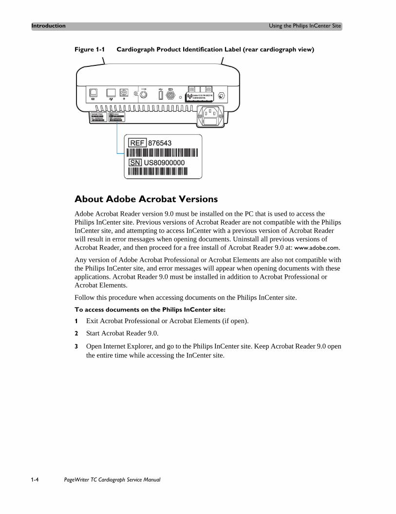
Registration for the InCenter site requires the serial number of at least one PageWriter TC cardiograph in active use at your facility. The serial number is found on the product identification label, located next to the text SN. The product identification label is located on the rear panel of the cardiograph, see (see Figure 1-1 on page 1-4).
PageWriter TC Cardiograph Service Manual 1-3
Introduction Using the Philips InCenter Site
Figure 1-1 Cardiograph Product Identification Label (rear cardiograph view)
About Adobe Acrobat VersionsAdobe Acrobat Reader version 9.0 must be installed on the PC that is used to access the Philips InCenter site. Previous versions of Acrobat Reader are not compatible with the Philips InCenter site, and attempting to access InCenter with a previous version of Acrobat Reader will result in error messages when opening documents. Uninstall all previous versions of Acrobat Reader, and then proceed for a free install of Acrobat Reader 9.0 at: www.adobe.com.
Any version of Adobe Acrobat Professional or Acrobat Elements are also not compatible with the Philips InCenter site, and error messages will appear when opening documents with these applications. Acrobat Reader 9.0 must be installed in addition to Acrobat Professional or Acrobat Elements.
Follow this procedure when accessing documents on the Philips InCenter site.
To access documents on the Philips InCenter site:
1 Exit Acrobat Professional or Acrobat Elements (if open).
2 Start Acrobat Reader 9.0.
3 Open Internet Explorer, and go to the Philips InCenter site. Keep Acrobat Reader 9.0 open the entire time while accessing the InCenter site.
1-4 PageWriter TC Cardiograph Service Manual

Safety Summary Introduction
Safety Summary
Symbols Marked on the Cardiograph or Patient Interface Module (PIM)
Symbol Name Description
Attention; read the Instructions for Use
See the PageWriter TC Cardiograph Instructions for Use.
Type CFDefibrillator Proof
ECG physio isolation is type CF, defibrillator proof. Suitable for all patient applications including direct cardiac application. System is in continuous operation.
DC Polarity Indicates the polarity of the DC power connector.
Direct Current Indicates that the equipment is suitable for direct current only.
PageWriter TC Cardiograph Service Manual 1-5

Introduction Safety Summary
Symbol Name Description
Disposal Dispose of in accordance with the requirements of your country.
ECG output signal The connector near this symbol provides access to an analog ECG signal that can be used as a synchronization signal for external devices, such as an imaging device. This analog ECG signal is not diagnostic quality and should not be used for ECG analysis purposes.
Local Area Network (LAN) Connector
Connect the Ethernet RJ45 LAN cable to the connector directly above this symbol to establish LAN connectivity.
Modem Connector Connect an analog phone line to the connector directly above this symbol.
Attention; read the Instructions for Use
See the PageWriter TC Cardiograph Instructions for Use.
Patient Interface Module (PIM) Connector
Connect the PIM patient data cable to the connector located directly above this symbol.
PCMCIA icon Insert the wireless LAN card into the slot located directly above this symbol.
PS/2 Connector Connect the Magnetic Card Reader or Barcode Reader to the connector located directly above this symbol.
Serial Number The number next to this symbol is the serial number of the cardiograph.
Symbols Marked on the Cardiograph or Patient Interface Module (PIM)
1-6 PageWriter TC Cardiograph Service Manual

Safety Summary Introduction
Symbol Name Description
On/Standby Pressing the button with this symbol on it puts the cardiograph into Standby (power saving mode).
USB Connector The connector near this symbol is used with a USB device.
Non-ionizing electromagnetic radiation
Interference may occur in the vicinity of equipment marked with this symbol.
Equipotential Grounding Post Equipotential grounding post used for establishing common ground between instruments.
Class II Protection against electric shock (PageWriter TC70 Cardiograph only).
Fuse The PageWriter TC50 Cardiograph and PageWriter TC30 Cardiograph contains a 1.6 amp (250V) time-delay fuse.
Symbols Marked on the Cardiograph or Patient Interface Module (PIM)
PageWriter TC Cardiograph Service Manual 1-7
Introduction Safety Summary
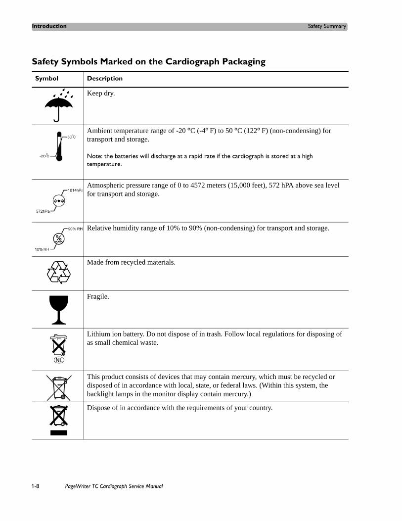
Safety Symbols Marked on the Cardiograph Packaging
Symbol Description
Keep dry.
Ambient temperature range of -20 oC (-4o F) to 50 oC (122o F) (non-condensing) for transport and storage.
Note: the batteries will discharge at a rapid rate if the cardiograph is stored at a high temperature.
Atmospheric pressure range of 0 to 4572 meters (15,000 feet), 572 hPA above sea level for transport and storage.
Relative humidity range of 10% to 90% (non-condensing) for transport and storage.
Made from recycled materials.
Fragile.
Lithium ion battery. Do not dispose of in trash. Follow local regulations for disposing of as small chemical waste.
This product consists of devices that may contain mercury, which must be recycled or disposed of in accordance with local, state, or federal laws. (Within this system, the backlight lamps in the monitor display contain mercury.)
Dispose of in accordance with the requirements of your country.
1-8 PageWriter TC Cardiograph Service Manual

Safety Summary Introduction
Safety and Regulatory Symbols Marked on the PageWriter TC70 Cardiograph Cart
Safety and Regulatory Symbols Marked on the PageWriter TC50/TC30 Cardiograph Cart
Symbol Name Description
Cart Transport Do not transport the cart with the drawer open.
Cart Drawer Weight Limit
Do not place more than 3 kilograms or 6.6 pounds of weight into the cart drawer.
Cart Storage Bin Weight Limit
Do not place more than 3 kilograms or 6.6 pounds of weight into the cart storage bin.
Symbol Name Description
Cart Storage Bin Weight Limit
Do not place more than 3 kilograms or 6.6 pounds of weight into the cart storage bin.
Optional Patient Cable Arm
Do not transport the cart with the patient cable arm positioned to the side. Only transport the cart with the patient cable arm positioned to the front of the cart.
PageWriter TC Cardiograph Service Manual 1-9

Introduction Safety Summary
Safety and Regulatory Symbols Marked on the PageWriter TC70 Cardiograph AC Power Adapter
Symbol Name Description
No serviceable parts inside
There are no serviceable parts inside the AC adapter. Do not open the AC adapter case.
Indoor, dry location use only
The AC adapter is only intended for indoor use in a dry location.
Attention; read the Instructions for Use
See the PageWriter TC Cardiograph Instructions for Use for information on the AC power adapter.
AC adapter disposal Dispose of in accordance with the requirements of your country.
1-10 PageWriter TC Cardiograph Service Manual
Important Patient and Safety Information Introduction
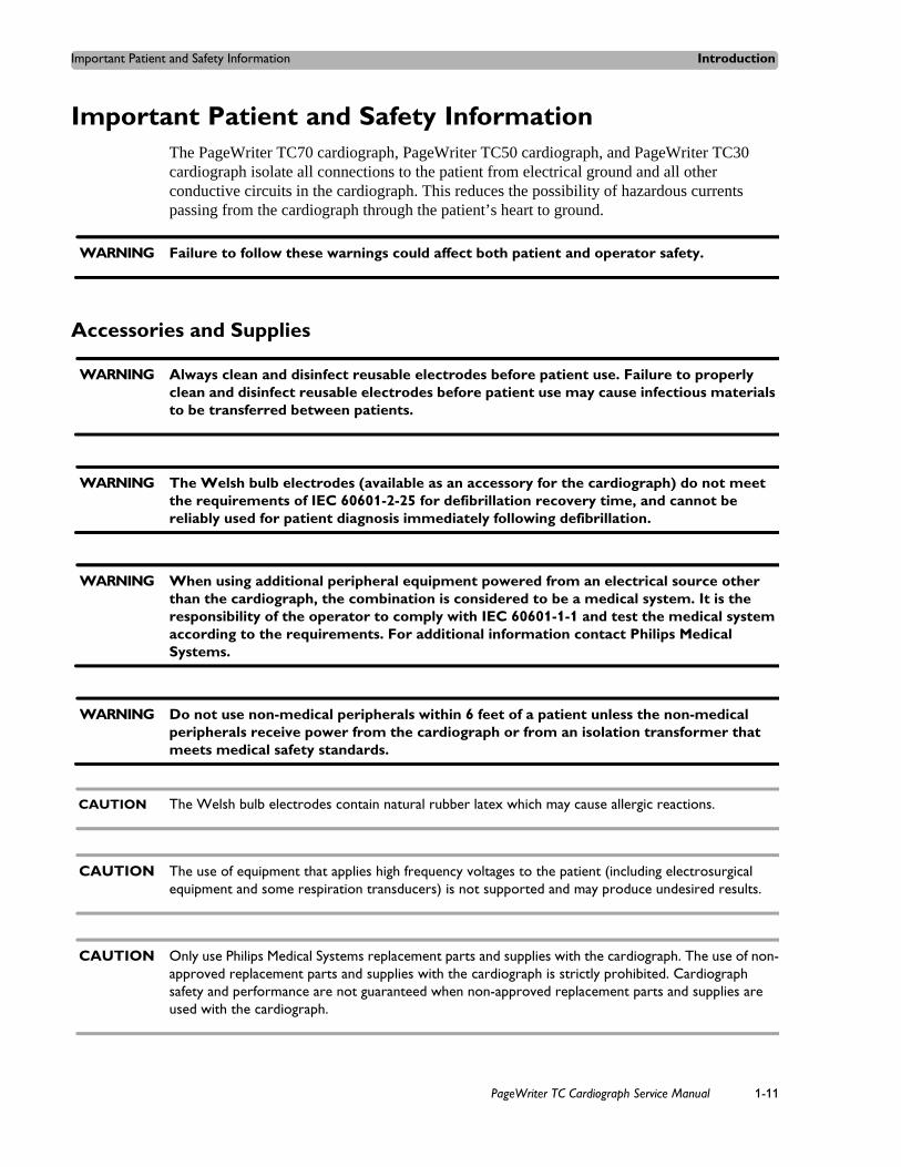
Important Patient and Safety InformationThe PageWriter TC70 cardiograph, PageWriter TC50 cardiograph, and PageWriter TC30 cardiograph isolate all connections to the patient from electrical ground and all other conductive circuits in the cardiograph. This reduces the possibility of hazardous currents passing from the cardiograph through the patient’s heart to ground.
WARNING Failure to follow these warnings could affect both patient and operator safety.
Accessories and Supplies
WARNING Always clean and disinfect reusable electrodes before patient use. Failure to properly clean and disinfect reusable electrodes before patient use may cause infectious materials to be transferred between patients.
WARNING The Welsh bulb electrodes (available as an accessory for the cardiograph) do not meet the requirements of IEC 60601-2-25 for defibrillation recovery time, and cannot be reliably used for patient diagnosis immediately following defibrillation.
WARNING When using additional peripheral equipment powered from an electrical source other than the cardiograph, the combination is considered to be a medical system. It is the responsibility of the operator to comply with IEC 60601-1-1 and test the medical system according to the requirements. For additional information contact Philips Medical Systems.
WARNING Do not use non-medical peripherals within 6 feet of a patient unless the non-medical peripherals receive power from the cardiograph or from an isolation transformer that meets medical safety standards.
CAUTION The Welsh bulb electrodes contain natural rubber latex which may cause allergic reactions.
CAUTION The use of equipment that applies high frequency voltages to the patient (including electrosurgical equipment and some respiration transducers) is not supported and may produce undesired results.
CAUTION Only use Philips Medical Systems replacement parts and supplies with the cardiograph. The use of non-approved replacement parts and supplies with the cardiograph is strictly prohibited. Cardiograph safety and performance are not guaranteed when non-approved replacement parts and supplies are used with the cardiograph.
PageWriter TC Cardiograph Service Manual 1-11

Introduction Important Patient and Safety Information
Using accessories, peripherals, or cables that are not supplied with the cardiograph or that are not recommended by Philips Medical Systems can result in increased emissions or decreased immunity of the cardiograph.
Connect other equipment in accordance with IEC 60601-1-1 Medical Electrical Systems Standard or IEC 60601-1: 2005 (3rd Edition) Medical Electrical Equipment Standard Clause 16 Medical Electrical Systems.
When connecting the cardiograph to other AC powered equipment, only connect equipment approved to IEC 60601-1 Medical Electrical Equipment or IEC 60950-1 Information Technology Equipment.
Only use patient electrodes that are approved by Philips Medical Systems. The use of non-approved patient electrodes may degrade cardiograph performance.
To prevent burns to the patient, remove all ECG electrodes and lead wires prior to the use of high frequency surgical equipment (including electrosurgical equipment and some respiration transducers).
AC Power Adapter and AC Power Cord
WARNING Only use the external power supply with part number 453564094411 with the PageWriter TC70 cardiograph in order to prevent electrical safety hazards. The use of any other power supply is not approved by Philips Medical Systems.
WARNING Whenever the AC power cord is connected to a live power outlet, ensure that it is also securely attached to the cardiograph. Always disconnect the AC power cord from the power outlet when it is not connected to the cardiograph.
WARNING Only use grounded power cords (three-wire power cords with grounded plugs) and grounded electrical outlets that are labeled as Hospital Only or Hospital Grade. NEVER adapt a grounded plug to fit an ungrounded outlet by removing the ground prong. Use the equipotential post when redundant earth ground is necessary according to IEC 60601-1-1.
CAUTION The power supply could feel warm to the touch.
The PageWriter TC70 cardiograph external power supply, part number 453564094411, is designed with a three wire supply system. The ground only serves a functional purpose for EMC and not protective earth for electrical safety. Use of an appropriate three-wire power cord is necessary to provide proper EMC operation.
1-12 PageWriter TC Cardiograph Service Manual

Important Patient and Safety Information Introduction
Only use the AC power adapter designed to be used with the PageWriter TC70 cardiograph, part number 453564094411, in order to ensure continued compliance with the requirements of IEC 60601-1.
To disconnect the cardiograph from AC power, unplug the cardiograph AC power cord from the mains power supply.
This equipment complies with the earth leakage current limits as specified in UL 60601-1:2003 Medical Electrical Equipment - General Requirements for Safety, only when connected to a 120 Volt mains power supply.
Periodically inspect the patient data cable, lead wires, and AC power cord for any worn or cracked insulation. Ensure that no exposed wires are visible on the AC power cord.
Only use the Philips Medical Systems AC power cord (part number 453564094411) supplied with the cardiograph. Use of any other power supply has not been verified and may lead to operator or patient harm, including electrical shock. Periodically inspect the AC power cord and AC power connector to ensure that both are in a safe and operable condition. If the AC power cord or AC power connector are not in a safe or operable condition, operate the cardiograph on battery power and contact Philips Medical Systems for service.
Analog ECG Output Signal Port
Do not use the analog ECG output signal port (not supported on cardiograph) for diagnostic purposes and do not use this signal for critical synchronization timing.
Do not connect any equipment to the cardiograph analog ECG output signal port that does not meet medical safety requirements and that has not been evaluated by local safety personnel.
Batteries
CAUTIONS Before removing and replacing batteries from the cardiograph, press down and hold the On/Standby button ( ) (located on the front of the cardiograph), to shut down the cardiograph. Ensure that the cardiograph is shut down. When the cardiograph is fully shut down, the screen is black, and the On/Standby button is not illuminated. Once the cardiograph is shut down, proceed to remove and replace the batteries.
When removing batteries from the cardiograph, the batteries could feel warm to the touch.
The battery capacity for the PageWriter TC50 cardiograph or PageWriter TC30 cardiograph with a single battery installed using the battery with Philips part number 989803170371, is 30 minutes of continuous Rhythm printing, or 30 total ECG reports.
When operating the PageWriter TC50 cardiograph or PageWriter TC30 cardiograph with one battery installed, only use the Philips battery with part number 989803170371. Do not use the battery with Philips part number 989803160981 for one battery operation.
When operating the PageWriter TC70 cardiograph, PageWriter TC50 cardiograph, or PageWriter TC30 cardiograph with two batteries installed, ensure that both batteries contain
PageWriter TC Cardiograph Service Manual 1-13

Introduction Important Patient and Safety Information
the same Philips part number. The battery part number identification label is found on the bottom of the battery. The cardiograph cannot operate with two batteries that contain different part numbers. If the cardiograph is operated with two batteries with different part numbers, the cardiograph will display an error message and will not operate.
PageWriter TC50/TC30 Cardiograph One Battery Operation The PageWriter TC50 cardiograph, or PageWriter TC30 cardiograph with installed
software version A.04.00 and higher can operate on a single battery with Philips part number 989803170371.
The battery capacity for the PageWriter TC50 cardiograph, or the PageWriter TC30 cardiograph with a single battery installed using the battery with Philips part number 989803170371, is 30 minutes of continuous Rhythm printing, or 30 total ECG reports.
When operating the PageWriter TC50 cardiograph, or the PageWriter TC30 cardiograph with one battery installed, only use the Philips battery with part number 989803170371. Do not use the battery with Philips part number 989803160981 for one battery operation.
When operating the PageWriter TC50 cardiograph or the PageWriter TC30 cardiograph with one battery installed, the single battery may be inserted into either battery compartment.
Cart
Ensure that the cardiograph is securely attached to the cardiograph cart before use.
Defibrillation
WARNING Do not touch the patient, patient data cable, leads, or the cardiograph during defibrillation. Death or injury may occur from the electrical shock delivered by the defibrillator.
Diagrams
Upon customer request, Philips Medical Systems will make available circuit diagrams, component part lists, descriptions, calibration instructions and other technical information.
Display Accuracy
The accuracy of the ECG signals are within +/- 5% (or +/- 40 uV whichever is greater), over a range of 0 to 5 mV, in the presence of differential and common mode DC offset voltages of +/- 300 mV. The cardiograph performance is tested to comply with the accuracy requirements over the dynamic ranges and frequency ranges specified in the IEC 60601-2-51 and AAMI EC-11 standards.
1-14 PageWriter TC Cardiograph Service Manual

Important Patient and Safety Information Introduction
For additional details regarding accuracy and precision, refer to the Physician's Guide and the Manufacturer's Disclosure Statement.
ECG Interpretation
CAUTION Always enter accurate patient information (including age and gender) if using the Philips DXL ECG Algorithm or Philips 12-Lead Algorithm for ECG interpretation.
Electrodes
Philips recommends the use of disposable electrodes at all times for all patient applications. Choose either adult or pediatric disposable electrodes based on the age and size of the patient. See “Disposable and Reusable Electrodes” on page 1-49 for information on ordering disposable electrodes.
Faxed ECGs
CAUTION No guarantee is made as to the suitability of a faxed ECG for any particular purpose, due to the variability inherent in fax technology.
CAUTION Faxed ECGs should only be sent to secure recipient fax machines.
General Cardiograph Use
WARNING Electrical shock hazard. Keep the cardiograph, Patient Interface Module (PIM), and all cardiograph accessories away from liquids. Do not immerse the cardiograph, PIM, or other accessories in any liquids.
WARNING Do not use this cardiograph near flammable anesthetics. It is not intended for use in explosive environments or in operating rooms. The disconnection or connection of AC power, or electrostatic discharge (ESD) may result in an electrical spark.
CAUTION The cardiograph may generate electromagnetic interference (EMI) that may cause nearby equipment to fail.
PageWriter TC Cardiograph Service Manual 1-15

Introduction Important Patient and Safety Information
CAUTION The use of equipment that applies high frequency voltages to the patient (including electrosurgical equipment and some respiration transducers) is not supported and may produce undesired results. Disconnect the patient data cable from the cardiograph, or detach the leads from the patient prior to performing any procedure that uses high frequency surgical equipment.
The use of non-Philips equipment connected to, or operating with, the PageWriter TC70 cardiograph, PageWriter TC50 cardiograph, or the PageWriter TC30 cardiograph is not tested or supported, and may produce undesired results.
Connecting multiple cardiographs to the same patient may pose a safety hazard due to the summation of leakage currents. Any combination of instruments should be evaluated by local safety personnel before being put into service.
IEC 60601-2-51
For information on the standard IEC 60601-2-51, please go to the Philips InCenter web site (incenter.medical.philips.com). For information on using the Philips InCenter site, see page 1-4.
Lead Wires
WARNING Electrical shock hazard. Do not touch accessible connector pins and the patient simultaneously.
WARNING Do not touch any loose or exposed leads during defibrillation. Death or injury may occur from the electrical shock delivered by the defibrillator.
WARNING Ensure that the electrodes or lead wires do not come in contact with any other conductive materials (including earth-grounded materials) especially when connecting or disconnecting electrodes to or from a patient.
Main Waveform Display Screen
Manual measurements of ECG intervals and magnitudes should be performed on printed ECG reports only. Do not make manual measurements of ECG intervals and magnitudes on the main waveform display screen since these ECG representations are scaled.
1-16 PageWriter TC Cardiograph Service Manual

Important Patient and Safety Information Introduction
Modem Card and Fax Feature
WARNING Do not connect the modem card to a phone line when the cardiograph is connected to a patient.
WARNING Only connect the phone line to the modem connector ( ) located on the rear panel of the cardiograph. Never attach the phone line to the LAN connector ( ).
No guarantee is made as to the suitability of a faxed ECG report for any particular purpose, due to the variability inherent in fax technology.
Pacemaker
Pace pulses may not be visible on a printed ECG report that uses simultaneous acquisition.
Patient Data Cable
WARNING The Philips Medical Systems patient data cable (supplied with cardiograph) is an integral part of the cardiograph safety features. Use of any other patient data cable may lead to the distortion or corruption of patient ECG data, may compromise defibrillation protection and degrade cardiograph performance, and overall cardiograph safety may be seriously degraded.
WARNING Ensure that the patient data cable is securely connected to the PIM Connector ( ) on the rear panel of the cardiograph.
The PageWriter TC50 cardiograph with installed software version A.03.00 and higher is only compatible with the Class B patient data cable (Philips part number 989803164281).
Keep the patient data cable away from power cords and any other electrical equipment. Failure to do so can result in AC power line frequency interference on the ECG trace.
Periodically inspect the patient data cable for any cracks or breaks in the cable insulation. If the integrity of the patient data cable is not assured, replace the patient data cable. Contact Philips Medical Systems for further assistance, see “Contacting a Philips Response Center” on page 5-13.
PageWriter TC Cardiograph Service Manual 1-17

Introduction Important Patient and Safety Information
Patient Interface Module (PIM)
WARNING Always clean and disinfect the Patient Interface Module (PIM) after patient use, if the PIM comes into direct contact with the patient’s skin. Failure to properly clean and disinfect the PIM after direct contact with the patient’s skin may cause infectious materials to be transferred between patients.
CAUTION If using the optional, 16-lead PIM, always ensure that the leads connected to the Patient Interface Module (PIM) are the same leads that are displayed on the cardiograph screen.
The PageWriter TC50 cardiograph with installed software version A.03.00 and higher is only compatible with the Class B 12-lead PIM (Philips part number 453564150741, AAMI and 453564150761, IEC) or the Class B 16-lead PIM (Philips part number 453564150751, AAMI and 453564150771, IEC).
Always put the cardiograph in Standby before replacing the Patient Interface Module (PIM). Do not change the PIM while the cardiograph is in active use.
Printer
CAUTION Do not pull on the paper while an ECG report is being printed. This can cause distortion of the waveform and can lead to potential misdiagnosis.
Servicing the Cardiograph
Only qualified personnel may service the cardiograph or may open the cardiograph housing to access internal cardiograph components. Do not open any covers on the cardiograph. There are no internal cardiograph components that are serviced by the operator.
The Philips Medical Systems warranty is applicable only if you use Philips Medical Systems approved accessories and replacement parts. See “Supplies and Ordering Information” on page 1-46 for more information.
Software
WARNING Only install Philips Medical Systems software on the cardiograph. The installation or use of software not approved by Philips Medical Systems is strictly prohibited and cardiograph safety and performance are not guaranteed.
1-18 PageWriter TC Cardiograph Service Manual

PageWriter TC70 Cardiograph Components Introduction
Touch Screen
WARNING Do not use sharp objects with the touch screen or apply excessive force to the touch screen. Applying excessive force to the touch screen may result in breaking the touch screen display and can cause sharp, jagged parts to expel to persons nearby.
Manual measurements of ECG intervals and magnitudes should be performed on printed ECG reports only. Do not make manual measurements of ECG intervals and magnitudes on the touch screen display since these ECG representations are scaled.
USB Memory Stick
WARNING Do not use the USB memory stick to import ECGs from other cardiographs, or other non-Philips devices onto any model of the PageWriter TC cardiograph.
CAUTIONS Only use the USB memory stick that is available for purchase as an optional accessory from Philips Medical Systems with the PageWriter TC cardiograph.
Do not insert a USB memory stick into the cardiograph, or remove a USB memory stick from the cardiograph when the cardiograph is acquiring ECG data from the patient.
Only use the USB memory stick to transfer data between the cardiograph and a computer. Do not use the USB memory stick with other devices.
Keep all USB memory sticks that contain patient data in a secure location where they cannot be accessed by unauthorized personnel. Always delete patient data from a USB memory stick promptly after use.
Affix a label to all USB memory sticks that contain patient data notifying users that unauthorized access of patient data on the USB memory stick is punishable by law.
Periodically inspect the USB connectors (side and rear of cardiograph) for any cracks or breaks. If the integrity of a USB connector is not assured, do not use the USB connector, and contact Philips Medical Systems for further assistance, see “Contacting a Philips Response Center” on page 5-13.
PageWriter TC70 Cardiograph ComponentsThe following sections include a description of all of the components of the PageWriter TC70 cardiograph, including the connection ports on the cardiograph, the Patient Interface Module (PIM), and optional accessories available with the cardiograph. For information on ordering any of the optional accessories for the cardiograph, see “PageWriter TC Cardiograph Supply Part Numbers” on page 5-8.
PageWriter TC Cardiograph Service Manual 1-19

Introduction PageWriter TC70 Cardiograph Components
Figure 1-2 PageWriter TC70 Cardiograph (left front view)
A Touch screen F ECG buttonB Audio speaker G Paper trayC AC power on indicator light H KeyboardD On/Standby buttonE ID button
A
B
D EC F
G
H
1-20 PageWriter TC Cardiograph Service Manual

PageWriter TC70 Cardiograph Components Introduction
Figure 1-3 PageWriter TC70 Cardiograph (right front view)
I Battery compartmentJ USB memory stick connector
I
J
PageWriter TC Cardiograph Service Manual 1-21
Introduction PageWriter TC70 Cardiograph Components
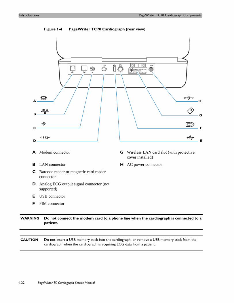
Figure 1-4 PageWriter TC70 Cardiograph (rear view)
WARNING Do not connect the modem card to a phone line when the cardiograph is connected to a patient.
CAUTION Do not insert a USB memory stick into the cardiograph, or remove a USB memory stick from the cardiograph when the cardiograph is acquiring ECG data from a patient.
A Modem connector G Wireless LAN card slot (with protective cover installed)
B LAN connector H AC power connector
C Barcode reader or magnetic card reader connector
D Analog ECG output signal connector (not supported)
E USB connector
F PIM connector
H
D
C
B
A
E
F
G
1-22 PageWriter TC Cardiograph Service Manual

PageWriter TC50 Cardiograph Components Introduction
PageWriter TC50 Cardiograph ComponentsThe following sections include a description of all of the components of the PageWriter TC50 cardiograph, including the connection ports on the cardiograph, the Patient Interface Module (PIM), and optional accessories available with the cardiograph. For information on ordering any of the optional accessories for the cardiograph, see “Supplies and Ordering Information” on page 5-7.
Figure 1-5 PageWriter TC50 Cardiograph (right front view)
A Touch screen F KeyboardB Audio speakers G AC power on indicator lightC Battery compartment H On/Standby buttonD USB memory stick connector I ID buttonE Paper tray J ECG button
A
B
D
E
CF
G H I J
PageWriter TC Cardiograph Service Manual 1-23

Introduction PageWriter TC50 Cardiograph Components
Figure 1-6 PageWriter TC50 Cardiograph (rear view)
WARNING Do not connect the modem card to a phone line when the cardiograph is connected to a patient.
CAUTIONS Do not insert a USB memory stick into the cardiograph, or remove a USB memory stick from the cardiograph when the cardiograph is acquiring ECG data from a patient.
Only use grounded power cords (three-wire power cords with grounded plugs) and grounded electrical outlets that are labelled as Hospital Only or Hospital Grade. Never adapt a grounded plug to fit an ungrounded outlet by removing the ground prong. Use the equipotential post when redundant earth ground is necessary according to IEC 60601-1-1.
A Wireless LAN card slot (with protective cover installed)
G Barcode reader or magnetic card reader connector
B Equipotential grounding post H LAN connector
C AC power cord connector I Modem connector
D PIM connector
E USB connector
F Analog ECG output signal connector (not supported)
H
D
C
B
A
EF
G
I
1-24 PageWriter TC Cardiograph Service Manual
PageWriter TC30 Cardiograph Components Introduction
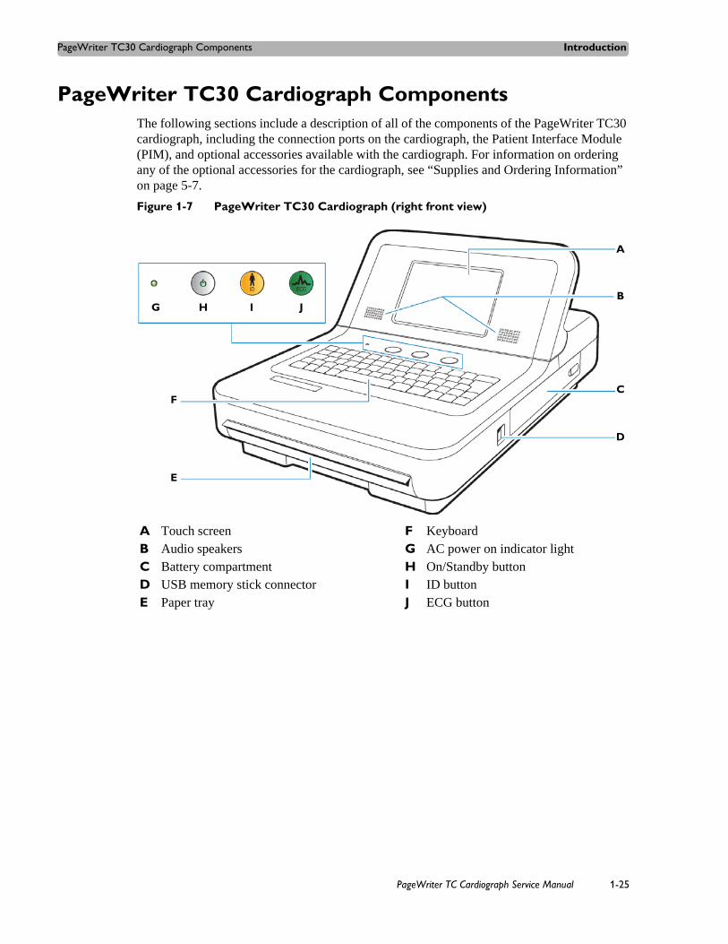
PageWriter TC30 Cardiograph ComponentsThe following sections include a description of all of the components of the PageWriter TC30 cardiograph, including the connection ports on the cardiograph, the Patient Interface Module (PIM), and optional accessories available with the cardiograph. For information on ordering any of the optional accessories for the cardiograph, see “Supplies and Ordering Information” on page 5-7.
Figure 1-7 PageWriter TC30 Cardiograph (right front view)
A Touch screen F KeyboardB Audio speakers G AC power on indicator lightC Battery compartment H On/Standby buttonD USB memory stick connector I ID buttonE Paper tray J ECG button
A
B
D
E
CF
G H I J
PageWriter TC Cardiograph Service Manual 1-25

Introduction PageWriter TC30 Cardiograph Components
Figure 1-8 PageWriter TC30 Cardiograph (rear view)
WARNING Do not connect the modem card to a phone line when the cardiograph is connected to a patient.
CAUTIONS Do not insert a USB memory stick into the cardiograph, or remove a USB memory stick from the cardiograph when the cardiograph is acquiring ECG data from a patient.
Only use grounded power cords (three-wire power cords with grounded plugs) and grounded electrical outlets that are labelled as Hospital Only or Hospital Grade. Never adapt a grounded plug to fit an ungrounded outlet by removing the ground prong. Use the equipotential post when redundant earth ground is necessary according to IEC 60601-1-1.
A Wireless LAN card slot (with protective cover installed)
G Barcode reader or magnetic card reader connector
B Equipotential grounding post H LAN connector
C AC power cord connector I Modem connector
D PIM connector
E USB connector
F Analog ECG output signal connector (not supported)
H
D
C
B
A
EF
G
I
1-26 PageWriter TC Cardiograph Service Manual

Patient Interface Module (PIM) Introduction
Patient Interface Module (PIM)The same Patient Interface Module (PIM) is used on all models of the PageWriter TC cardiograph. The PIM is a hand-held device that connects to the patient data cable. The PIM is available in a standard 12-lead, or for the PageWriter TC70 and TC50 cardiographs, an optional 16-lead model is available. For information on configuring the optional 16-lead PIM, see “Configuring the 16-Lead PIM (PageWriter TC70 and PageWriter TC50 cardiograph only)” on page 1-31.
NOTE Figure 1-9 shows AAMI version PIMs.
Figure 1-9 16-lead (left) and 12-lead (right) Patient Interface Module (PIM)
About Class A and Class B Patient Data Cables and PIMsPrior to August, 2009, PageWriter TC70 cardiographs with installed software version A.02.00 and lower were shipped from Philips Medical Systems with Class A patient data cables and Class A PIMs. All PageWriter TC70 cardiographs and PageWriter TC50 cardiographs with installed software version A.03.00 and higher are shipped from Philips Medical Systems with Class B patient data cables and Class B PIMs.
The only visual difference between a Class A and a Class B PIM or patient data cable is the number of connectors on the PIM, and the number of pins on the PIM connector end of the patient data cable. All Class A devices have 5 connectors/pins on the PIM connector, and on the PIM connector end of the patient data cable. All Class B devices have 8 connectors/pins on the PIM connector, and on the PIM connector end of the patient data cable.
NOTE Both Class A and Class B patient data cables have 5 pins on the connector end that attaches to the cardiograph.
Class A patient data cables can only be used with a Class A PIM on the PageWriter TC70 cardiograph. Class B patient data cables can only be used with a Class B PIM on any model of the PageWriter TC cardiograph. When ordering replacement patient data cables or PIMs from
PageWriter TC Cardiograph Service Manual 1-27

Introduction Patient Interface Module (PIM)
Philips Medical Systems, check the number of connectors on the PIM, and also check the number of pins on the PIM connector end of the patient data cable to ensure that you are ordering the correct Class A or Class B device.
NOTE If you are unable to connect a patient data cable to a PIM connector, check that both devices are compatible. You cannot connect a Class A patient data cable to a Class B PIM.
Figure 1-10 Class A and Class B Patient Data Cable Connectors
Figure 1-11 Class A and Class B Patient Interface Module (PIM) Connectors
Attaching the Patient Data Cable to the PIM and CardiographThe patient data cable must be attached to the PIM connector before use. Once attached to the PIM, the patient data cable is then attached to the cardiograph through the appropriate PIM connector on the rear of the cardiograph.
WARNING Ensure that the patient data cable is securely connected to the PIM connector ( ) on the rear panel of the cardiograph.
A Class A patient data cable (5 pins) B Class B patient data cable (8 pins)
A Class A PIM (5 connectors) B Class B PIM (8 connectors)
A B
A B
1-28 PageWriter TC Cardiograph Service Manual
Patient Interface Module (PIM) Introduction
WARNING The Philips Medical Systems patient data cable (supplied with cardiograph) is an integral part of the cardiograph safety features. Use of any other patient data cable may lead to the distortion or corruption of patient ECG data, may compromise defibrillation protection and degrade cardiograph performance, and overall cardiograph safety may be seriously degraded.
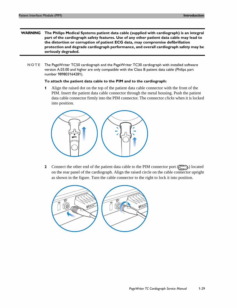
NOTE The PageWriter TC50 cardiograph and the PageWriter TC30 cardiograph with installed software version A.03.00 and higher are only compatible with the Class B patient data cable (Philips part number 989803164281).
To attach the patient data cable to the PIM and to the cardiograph:
1 Align the raised dot on the top of the patient data cable connector with the front of the PIM. Insert the patient data cable connector through the metal housing. Push the patient data cable connector firmly into the PIM connector. The connector clicks when it is locked into position.
2 Connect the other end of the patient data cable to the PIM connector port ( ) located on the rear panel of the cardiograph. Align the raised circle on the cable connector upright as shown in the figure. Turn the cable connector to the right to lock it into position.
PageWriter TC Cardiograph Service Manual 1-29
Introduction Patient Interface Module (PIM)
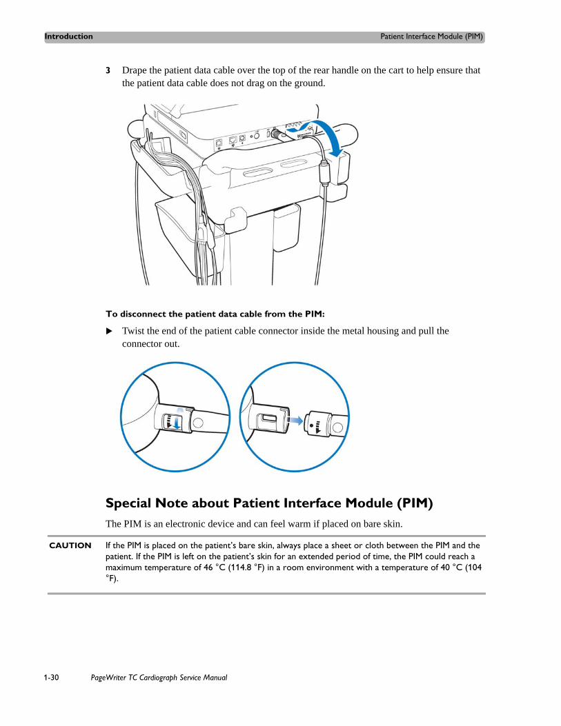
3 Drape the patient data cable over the top of the rear handle on the cart to help ensure that the patient data cable does not drag on the ground.
To disconnect the patient data cable from the PIM:
Twist the end of the patient cable connector inside the metal housing and pull the connector out.
Special Note about Patient Interface Module (PIM)The PIM is an electronic device and can feel warm if placed on bare skin.
CAUTION If the PIM is placed on the patient’s bare skin, always place a sheet or cloth between the PIM and the patient. If the PIM is left on the patient’s skin for an extended period of time, the PIM could reach a maximum temperature of 46 °C (114.8 °F) in a room environment with a temperature of 40 °C (104 °F).
1-30 PageWriter TC Cardiograph Service Manual

Patient Interface Module (PIM) Introduction
Figure 1-12 Placing PIM on patient’s skin
PIM ECG ButtonThe PIM has an ECG button that is used to take ECGs from the bedside.
Figure 1-13 ECG button on PIM
Configuring the 16-Lead PIM (PageWriter TC70 and PageWriter TC50 cardiograph only)The optional 16-lead PIM may be configured to support up to 16 optional leads for adult and pediatric application. The 16-lead PIM is shipped with four optional leads, color clip identifiers, and shorting plugs. For information on ordering the 16-lead PIM option, see “Supplies and Ordering Information” on page 5-7.
NOTE The 16-lead PIM is not available with the PageWriter TC30 cardiograph.
A Cloth placed between PIM and patient
A PIM ECG button
A
A
PageWriter TC Cardiograph Service Manual 1-31

Introduction Patient Interface Module (PIM)
CAUTION When using the 16-lead PIM, always ensure that the leads connected to the Patient Interface Module (PIM) are the same leads that are displayed on the cardiograph screen.
Figure 1-14 16-Lead PIM Kit
To configure the 16-lead PIM:
1 Press the On/Standby button ( ) to put the cardiograph into Standby.
CAUTION Always put the cardiograph in Standby before connecting or disconnecting the Patient Interface Module (PIM). Do not disconnect or connect the PIM to the cardiograph while the cardiograph is in active use.
2 Disconnect the PIM from the cardiograph, if necessary.
3 There are six optional lead connectors available on the PIM. These optional lead connectors are labeled: C3R/V3R, C4R/V4R, C5R/V5R, C7/V7, C8/V8 and C9/V9. Any of these optional leads (up to a maximum of four) may be configured for use with the cardiograph.
NOTE The cardiograph does not support the configuration of 18 leads. Any of the optional leads, up to a maximum of 4, may be configured for use with the cardiograph.
A Color identification clips C Lead separator
B Optional leads (4 total) D Shorting plug (6 total)
A
B
C
D
1-32 PageWriter TC Cardiograph Service Manual
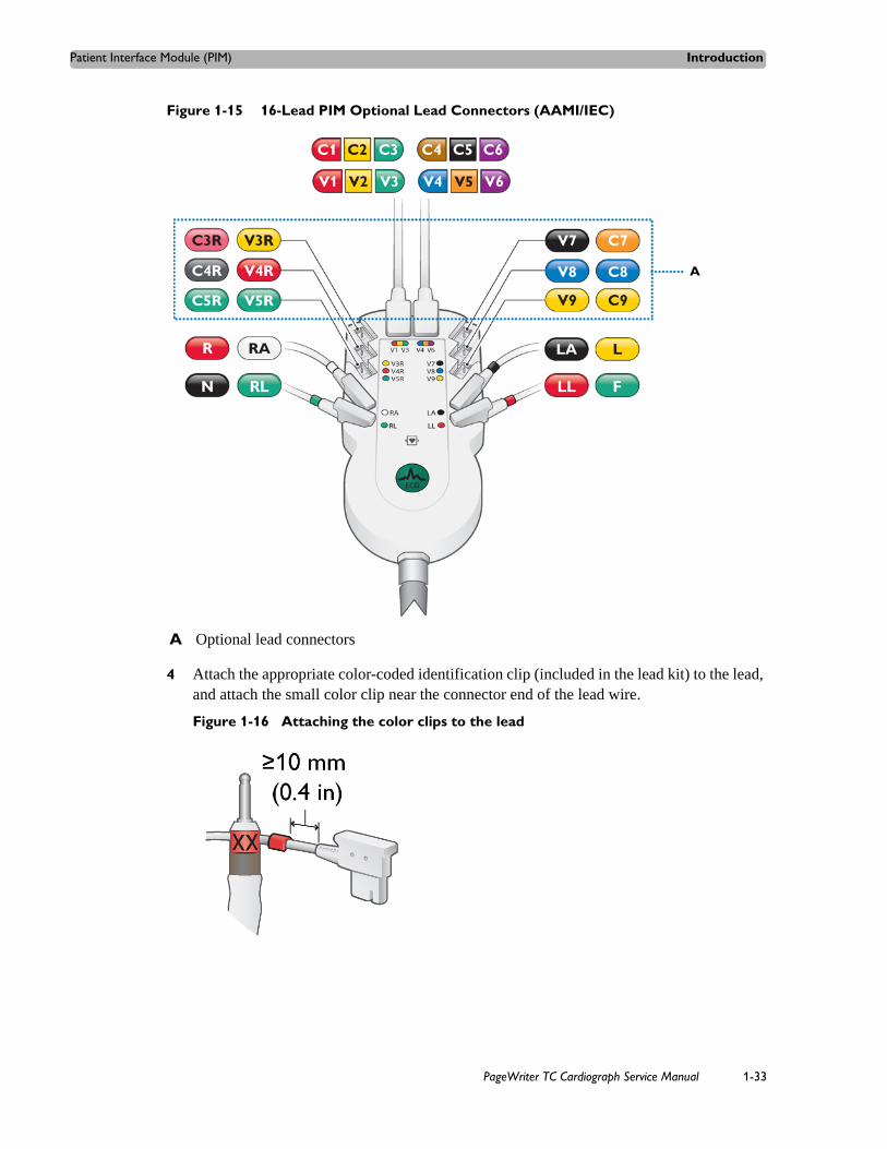
Patient Interface Module (PIM) Introduction
Figure 1-15 16-Lead PIM Optional Lead Connectors (AAMI/IEC)
4 Attach the appropriate color-coded identification clip (included in the lead kit) to the lead, and attach the small color clip near the connector end of the lead wire.
Figure 1-16 Attaching the color clips to the lead
A Optional lead connectors
A
PageWriter TC Cardiograph Service Manual 1-33

Introduction Patient Interface Module (PIM)
5 Attach the lead to the correct lead connector on the PIM. If any lead connectors on the PIM are left empty, insert a shorting plug (included in kit).
Figure 1-17 Shorting Plug (included in Lead Kit)
NOTE To configure the 16-lead PIM for standard 12 leads, insert shorting plugs into all of the optional lead connectors.
6 Ensure that each lead is firmly connected to the PIM.
Recommended 16-Lead Configurations
Table 1-1 provides some suggested configurations of the 16-lead Patient Interface Module (PIM) for adult and pediatric application.
NOTE The recommended 16-lead configuration options described in Table 1-1 are the only 16-lead options that are compatible with the TraceMaster ECG Management System.
Table 1-1 15 and 16-Lead PIM Configuration Options
Lead Option Standard 12-leads plus extended leads (AAMI/IEC)
Lead Placement
Pediatric (15 leads)
V3R/C3R, V4R/C4R, V7/C7
Posterior (15 leads)
V7/C7, V8/C8, V9/C9
1-34 PageWriter TC Cardiograph Service Manual

Installing the Batteries Introduction
Installing the BatteriesThe PageWriter TC70 cardiograph is shipped with two batteries, and the PageWriter TC50 and PageWriter TC30 cardiographs are shipped with one or an optional two batteries that are used to power the cardiograph when AC power is not available.
CAUTION Insert the batteries into the cardiograph before plugging the cardiograph into AC power.
Notes about Battery InstallationNOTES If operating the PageWriter TC50 or PageWriter TC30 cardiograph with one battery installed, the
battery may be inserted into either battery compartment.
When operating the PageWriter TC50 or PageWriter TC30 cardiograph with one battery installed, only use the Philips battery with part number 989803170371. Do not use the battery with Philips part number 989803160981 for one battery operation.
When operating any model of the PageWriter TC cardiograph with two batteries installed, ensure that both batteries contain the same Philips part number. The battery part number identification label is found on the bottom of the battery. The cardiograph cannot operate with two batteries that contain different part numbers. If the cardiograph is operated with two batteries with different part numbers, the cardiograph will display an error message and will not operate.
Balanced(16 leads)
V3R/C3R, V4R/C4R, V7/C7, V8/C8
Table 1-1 15 and 16-Lead PIM Configuration Options (continued)
Lead Option Standard 12-leads plus extended leads (AAMI/IEC)
Lead Placement
PageWriter TC Cardiograph Service Manual 1-35

Introduction Installing the Batteries
To install the batteries:
1 Open the battery door.
2 Locate the two gold pull tabs inside of the battery compartment. Pull the tabs straight out of the battery compartment and lay flat.
1-36 PageWriter TC Cardiograph Service Manual

Installing the Batteries Introduction
3 Insert the battery with the external connector facing the bottom rear of the compartment.
NOTE If operating the PageWriter TC50 or the PageWriter TC30 cardiograph with a single battery installed, the battery may be inserted into either battery compartment.
4 Push in the battery and ensure that the battery is fully inserted into the slot. The pull tab will insert along with the battery. If necessary, insert the second battery following the same procedure.
PageWriter TC Cardiograph Service Manual 1-37

Introduction Installing the Batteries
5 Reinstall the battery door.
6 Connect the AC power cord to the cardiograph. Charge the batteries for five hours before operating the cardiograph on battery power only.
Charging the BatteriesCharge the batteries for five hours prior to initial use. Plug the cardiograph into AC power whenever possible, and fully charge the batteries. Proper battery maintenance and care, including frequent and full charging of the batteries, will help to prolong battery life.
There are configurable power saving features available on the cardiograph. These features are used to help prolong overall battery life, and to optimize battery power use between battery charges.
1-38 PageWriter TC Cardiograph Service Manual
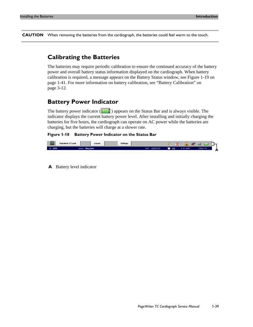
Installing the Batteries Introduction
CAUTION When removing the batteries from the cardiograph, the batteries could feel warm to the touch.
Calibrating the BatteriesThe batteries may require periodic calibration to ensure the continued accuracy of the battery power and overall battery status information displayed on the cardiograph. When battery calibration is required, a message appears on the Battery Status window, see Figure 1-19 on page 1-41. For more information on battery calibration, see “Battery Calibration” on page 3-12.
Battery Power IndicatorThe battery power indicator ( ) appears on the Status Bar and is always visible. The indicator displays the current battery power level. After installing and initially charging the batteries for five hours, the cardiograph can operate on AC power while the batteries are charging, but the batteries will charge at a slower rate.
Figure 1-18 Battery Power Indicator on the Status Bar
A Battery level indicator
A
PageWriter TC Cardiograph Service Manual 1-39
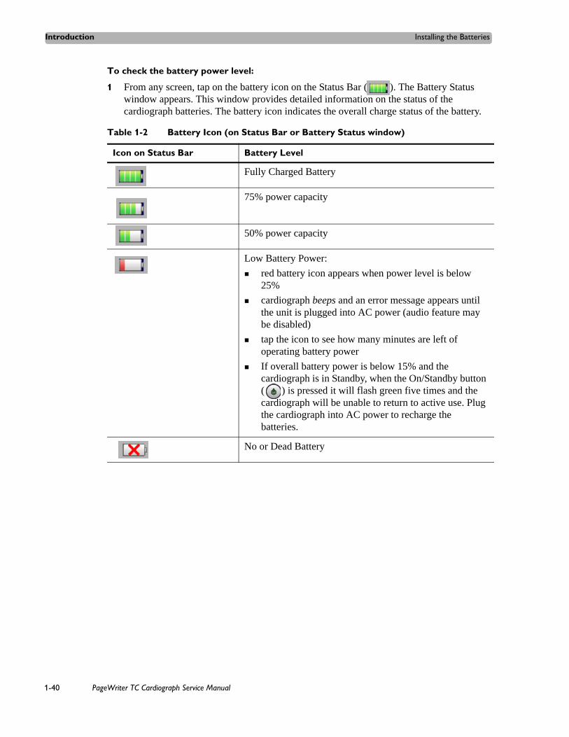
Introduction Installing the Batteries
To check the battery power level:
1 From any screen, tap on the battery icon on the Status Bar ( ). The Battery Status window appears. This window provides detailed information on the status of the cardiograph batteries. The battery icon indicates the overall charge status of the battery.
Table 1-2 Battery Icon (on Status Bar or Battery Status window)
Icon on Status Bar Battery Level
Fully Charged Battery
75% power capacity
50% power capacity
Low Battery Power:
red battery icon appears when power level is below 25%
cardiograph beeps and an error message appears until the unit is plugged into AC power (audio feature may be disabled)
tap the icon to see how many minutes are left of operating battery power
If overall battery power is below 15% and the cardiograph is in Standby, when the On/Standby button ( ) is pressed it will flash green five times and the cardiograph will be unable to return to active use. Plug the cardiograph into AC power to recharge the batteries.
No or Dead Battery
1-40 PageWriter TC Cardiograph Service Manual

Using the On/Standby Button Introduction
NOTE If the Plug in the Cardiograph message appears, the cardiograph needs to be plugged into AC power immediately.
Figure 1-19 Battery Status Information with Plug in the Cardiograph message
2 Touch the Close button to close the window.
Using the On/Standby ButtonThe On/Standby button ( ) is used to:
put the cardiograph into Standby when not in active use in order to conserve battery power
shut down all power to the cardiograph for extended periods of inactivity
return the cardiograph to active use
CAUTION Ensure that all patient data from an active patient session is saved before entering Standby, or shutting down the cardiograph. Unsaved patient data (patient identification information, unreviewed Event Markers, unsaved ECGs) are deleted when the cardiograph enters Standby.
To put the cardiograph into Standby (power save):
1 Press the On/Standby button gently to put the cardiograph into Standby. When the cardiograph is in Standby, the screen is black.
TIP Plug the cardiograph into AC power whenever possible to recharge the batteries.
2 Press the On/Standby button again to return the cardiograph to active use. The previously viewed screen (prior to entering Standby) appears.
PageWriter TC Cardiograph Service Manual 1-41

Introduction Using the Wireless LAN Card
NOTES If overall battery power is below 15% and the cardiograph is in Standby, when the On/Standby button is pressed it will flash green five times and the cardiograph will be unable to return to active use. Plug the cardiograph into AC power to recharge the batteries.
If the Disclose or Rhythm screens are viewed prior to entering Standby, the Main screen will appear when the cardiograph is returned to active use.
To shut down the cardiograph:
1 Press and hold the On/Standby button for 3 seconds to shut down the cardiograph. When the cardiograph is shut down, any unsaved patient data is lost.
2 Press the On/Standby button to return the cardiograph to active use. The cardiograph fully restarts and the Main screen appears.
Using the Wireless LAN CardThe PageWriter TC cardiograph supports wireless connectivity which is used to transfer ECG and order data between the cardiograph and a TraceMaster ECG Management System. The cardiograph can also be configured to transfer ECG data using a wireless connection to a third party ECG management system. For information on configuring cardiograph connectivity with a TraceMaster or other third party ECG management system, see the PageWriter TC Cardiograph Network Configuration Guide available on the User Documentation and Training DVD, or the file can be downloaded from the Philips InCenter site.
CAUTION Only use wireless LAN cards with the PageWriter TC cardiograph that have been purchased from Philips Medical Systems. The use of non-approved wireless LAN cards with either model cardiograph is not tested or supported, and Philips Medical Systems does not guarantee cardiograph operation or wireless LAN connectivity.
For information on installing the card and configuring the cardiograph for wireless transmission, see the PageWriter TC Cardiograph Wireless LAN Installation Instructions. The file is available for download from the Philips InCenter site (incenter.medical.philips.com).
For information on ordering the wireless card, see “Supplies and Ordering Information” on page 5-7.
1-42 PageWriter TC Cardiograph Service Manual

Using the Modem Card Introduction
Using the Modem Card The modem card is an optional accessory that is used to fax ECGs to a configured receiving fax machine, or is used to transfer ECGs or orders by modem between the cardiograph and a TraceMaster ECG Management System. The cardiograph can also be configured to transfer ECG data by modem to a third party ECG management system. For information on configuring cardiograph connectivity with a TraceMaster or other third party ECG management system, see the PageWriter TC Cardiograph Network Configuration Guide available on the User Documentation and Training DVD, or the file can be downloaded from the Philips InCenter site.
For information on ordering the modem card, see “Supplies and Ordering Information” on page 5-7.
WARNING Do not connect the modem card to a phone line when the cardiograph is connected to a patient.
Using the USB Memory StickThe USB memory stick is an optional accessory that is used to transfer orders to the cardiograph from a computer that has the WebSelect Utility installed, and can also be used to transfer completed ECGs (as either an XML or as a PDF file) from the cardiograph to a TraceMaster ECG Management System, remote networked PC or server, or other third party ECG management system. The USB memory stick can also be used to save custom settings specified on the Setup screens as a Custom Settings file. This Custom Settings file can then be transferred to additional cardiographs to help speed up the configuration process.
For information on using the WebSelect Utility, see the Using OrderVue with PageWriter Cardiographs guide. This guide is available for download from the Philips InCenter site. For information on the Philips InCenter site, See "Using the Philips InCenter Site" on page 1-3
CAUTION The PageWriter TC cardiographs only support the USB memory stick that is available for purchase as an optional accessory from Philips Medical Systems. Philips does not guarantee that other USB memory sticks are compatible with the PageWriter TC cardiographs.
PageWriter TC Cardiograph Service Manual 1-43
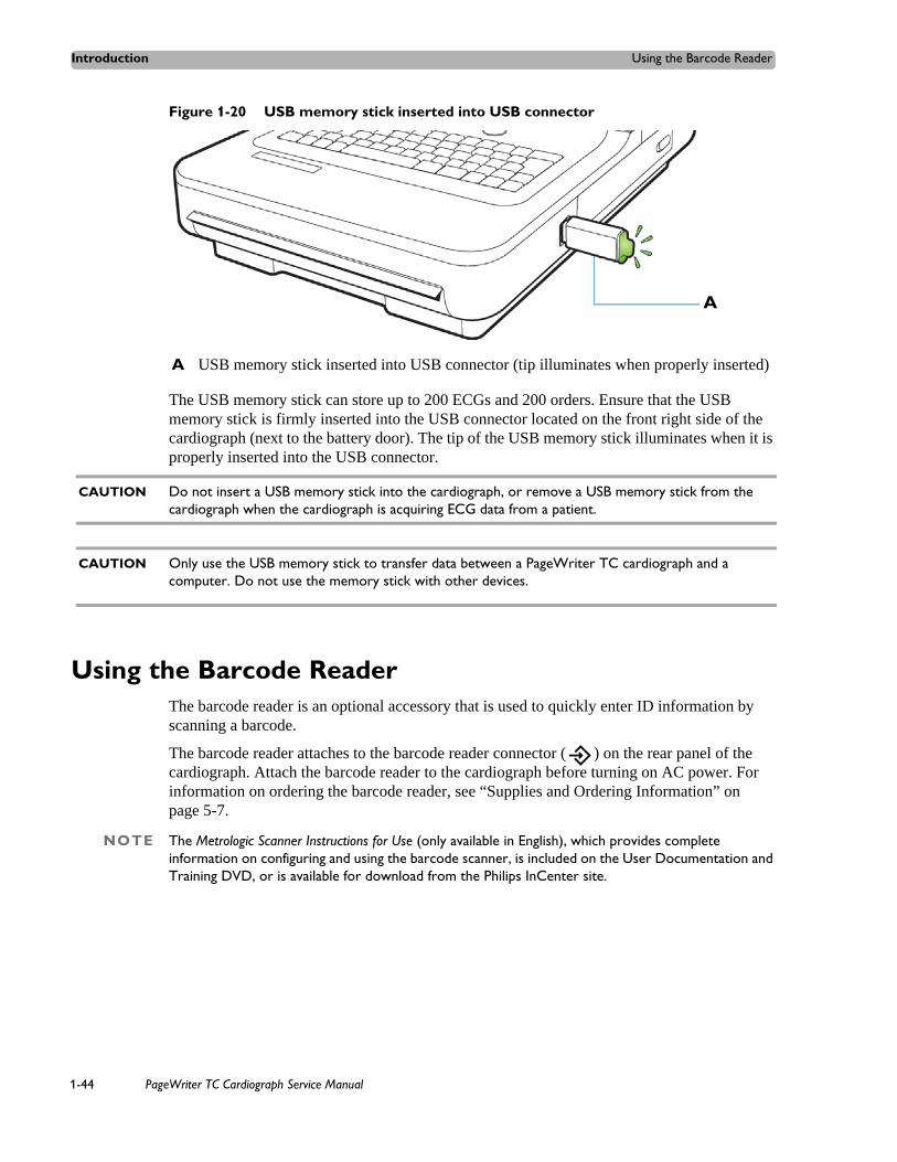
Introduction Using the Barcode Reader
Figure 1-20 USB memory stick inserted into USB connector
The USB memory stick can store up to 200 ECGs and 200 orders. Ensure that the USB memory stick is firmly inserted into the USB connector located on the front right side of the cardiograph (next to the battery door). The tip of the USB memory stick illuminates when it is properly inserted into the USB connector.
CAUTION Do not insert a USB memory stick into the cardiograph, or remove a USB memory stick from the cardiograph when the cardiograph is acquiring ECG data from a patient.
CAUTION Only use the USB memory stick to transfer data between a PageWriter TC cardiograph and a computer. Do not use the memory stick with other devices.
Using the Barcode ReaderThe barcode reader is an optional accessory that is used to quickly enter ID information by scanning a barcode.
The barcode reader attaches to the barcode reader connector ( ) on the rear panel of the cardiograph. Attach the barcode reader to the cardiograph before turning on AC power. For information on ordering the barcode reader, see “Supplies and Ordering Information” on page 5-7.
NOTE The Metrologic Scanner Instructions for Use (only available in English), which provides complete information on configuring and using the barcode scanner, is included on the User Documentation and Training DVD, or is available for download from the Philips InCenter site.
A USB memory stick inserted into USB connector (tip illuminates when properly inserted)
A
1-44 PageWriter TC Cardiograph Service Manual

Using the Cardiograph Touch Screen Introduction
Figure 1-21 The Barcode Reader
Using the Cardiograph Touch Screen The touch screen provides access to all of the cardiograph features. Simply touch the buttons on the screen to open the different screens and to perform different functions.
PageWriter TC Cardiograph Service Manual 1-45
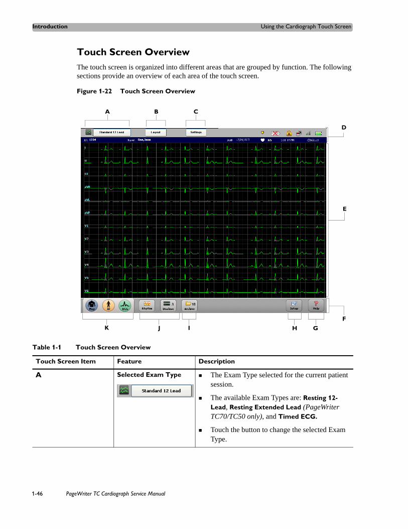
Introduction Using the Cardiograph Touch Screen
Touch Screen OverviewThe touch screen is organized into different areas that are grouped by function. The following sections provide an overview of each area of the touch screen.
Figure 1-22 Touch Screen Overview
J
A B C
D
E
F
GHIK
Table 1-1 Touch Screen Overview
Touch Screen Item Feature Description
A Selected Exam Type The Exam Type selected for the current patient session.
The available Exam Types are: Resting 12-Lead, Resting Extended Lead (PageWriter TC70/TC50 only), and Timed ECG.
Touch the button to change the selected Exam Type.
1-46 PageWriter TC Cardiograph Service Manual

Using the Cardiograph Touch Screen Introduction
B Exam Layout The settings underneath this button include the selected ECG report layout settings, and the level of interpretation generated by the Philips algorithm that are being applied to the selected Exam Type.
Any of the settings on this screen may be edited, and the new settings are applied to the current patient session.
C Current Operating Settings
The settings underneath this button include the selected filters (Artifact, Baseline Wander), pacing detection setting, and report scaling settings being applied to the current patient session.
The Unknown pacing setting is recommended for most ECGs.
D Status Bar Displays information about the current cardiograph settings, including selected Exam Type, current patient name, network connectivity status, PIM status, and the current date and time.
See "The Status Bar" on page 1-51.
E Waveform Display Display area for ECG waveforms. Lead connection quality is indicated by the color of the waveform.
Press the up arrow ( ) or the down arrow ( ) key (on keyboard) to change the displayed lead format.
F Toolbar All cardiograph ECG acquisition modes and ECG management features.
G Help Provides information on how to use the cardiograph.
H Setup The settings underneath this button are used to configure or change cardiograph settings, or to access the service utilities. Access to these screens may require entering a password.
Table 1-1 Touch Screen Overview (continued)
Touch Screen Item Feature Description
PageWriter TC Cardiograph Service Manual 1-47

Introduction Using the Cardiograph Touch Screen
I ECG Storage and Management Features
Provides access to the ECG Archive, which is used as temporary storage for all ECGs acquired on the cardiograph.
From the Archive, ECGs may be transferred (as an XML file or as a PDF file) to a TraceMaster ECG Management System, a third party ECG management system, a USB memory stick, or as a PDF file only to a configured networked remote PC or server.
From the Archive, a TraceMaster server may be searched for previous ECGs to view and print on the cardiograph.
The number on the button (9) displays the number of ECGs currently stored in the Archive.
J Rhythm and Disclose Features
The Rhythm feature is used to print continuous rhythm strips until the Stop button is touched.
The Disclose feature is used to review captured Events, to view continuous data from one selected lead, or to print ECG reports in a variety of formats.
The number on the Disclose button (0) displays the number of Events currently stored in Disclose.
K 1-2-3 Operation Features
The Map, ID, and ECG buttons are used in sequence to acquire and print an ECG.
Table 1-1 Touch Screen Overview (continued)
Touch Screen Item Feature Description
1-48 PageWriter TC Cardiograph Service Manual

Using the Cardiograph Touch Screen Introduction
Changing the Lead Format on the Main ECG ScreenThe format of the waveforms that display on the Main screen can be changed at any time. The available lead formats are described in Table 1-3.
Table 1-3 Main Screen Lead Formats
Lead Format Description
12x1 or 16x1 This view provides ten seconds of continuous ECG waveform data for each available lead
The 16x1 format is only available with the PageWriter TC70 cardiograph with the 16-lead option
The PageWriter TC50 cardiograph with the 16-lead option will only display the 12x1 view; to view all 16 leads select the split screen view (see below)
6x2 (12-lead option) or Split Screen View (16-lead option)
This view provides five seconds of continuous ECG waveform data for each lead on a split screen
In the split screen display, the limb and augmented leads are on the left, and the precordial leads are on the right for both the 12-lead and the 16-lead display option
For the TC30 cardiograph only, this is the default lead format on the cardiograph, see (see Figure 1-23 on page 1-50)
3x4 This view provides 2.5 seconds of waveform data for each lead, with 3 total rows with 4 leads in each row
In this view, the limb and augmented leads are on the left, and the precordial leads are on the right
In this view, only 12 leads are displayed even if the 16-lead option is being used
PageWriter TC Cardiograph Service Manual 1-49

Introduction Using the Cardiograph Touch Screen
Figure 1-23 Main Screen with Split Screen View (12 Leads Displayed)
To change the lead display on the main screen:
1 Press the down arrow key (on keyboard) or the up arrow key to scroll through the available Main screen lead formats.
2 Press the up arrow key (on keyboard) to change the display back to the original view.
3 For the TC30 cardiograph only, the lead format that displays on the Main screen when the cardiograph is shut down (by pressing and holding the On/Standby button ( ) will be retained once the cardiograph is returned to active use.
BA
A Limb Leads B Precordial Leads
1-50 PageWriter TC Cardiograph Service Manual

Using the Cardiograph Touch Screen Introduction
The Status BarThe Status Bar (top of the screen) provides information about the current cardiograph settings. The Status Bar is always visible.
Figure 1-24 The Status Bar
Table 1-4 The Status Bar
Status Bar Item Feature Description
A Selected Exam Type The Exam Type selected for the current patient session.
The available Exam Types are: Resting 12-Lead, Resting Extended Lead (PageWriter TC70/TC50 only), and Timed ECG.
B ECG Layout The current ECG report layout settings, including the level of interpretation generated by the algorithm.
Any of the settings on this screen may be edited for the current patient session.
C Operating Settings The current selected filters (Artifact, Baseline Wander), pacing detection setting, and report scaling settings.
The Unknown pacing setting is recommended for most ECGs.
D Event Marker Alert If this flashing icon appears, saved Event markers ( ) have not yet been reviewed on the Disclose screen, and will be deleted within the next 5 minutes (TC70 cardiograph), the next 2 minutes (TC50 cardiograph), or the next 75 seconds (TC30 cardiograph).
Touch the Disclose button on the toolbar to review saved Events.
A B C D E F G H
IJK
PageWriter TC Cardiograph Service Manual 1-51

Introduction Using the Cardiograph Touch Screen
E PIM Disconnected If this icon appears, the Patient Interface Module (PIM) is not connected to the cardiograph.
Check that the PIM cable is firmly attached to the connector on the cardiograph, and that there are no breaks or cracks in the cable.
F Caps Lock Indicates that the Caps Lock setting is enabled (keyboard types in all capital letters).
Touch the Caps Lock key (on keyboard) to disable the setting.
G LAN and Wireless LAN Connectivity
LAN connectivity:
Indicates if the cardiograph is connected to a live Ethernet connection through the LAN connector ( ) on the rear of the cardiograph.
If no LAN connection is detected, a red “x” mark appears on the icon ( ).
Wireless LAN connectivity:
Indicates the signal strength of a the wireless LAN connection.
Green bars indicate that the wireless adapter is associated to an access point. The higher the number of green bars, the better the connection.
No bars indicates that the cardiograph is losing the wireless LAN signal and that the cardiograph should be moved to an area with a stronger signal.
Gray inactive bars ( ) indicate that the wireless adapter is unable to associate to an access point.
H Battery Power Indicator Displays the available battery power. For more information, see “Battery Power Indicator” on page 1-39.
Table 1-4 The Status Bar (continued)
Status Bar Item Feature Description
1-52 PageWriter TC Cardiograph Service Manual

Using the Keyboard Shortcuts Introduction
Using the Keyboard ShortcutsThe following key stroke combinations can be used from any cardiograph screen.
Table 1-5 Keyboard Shortcuts
I Date and Time Displays the current date and time.
The date and time can be set manually, or the cardiograph can be configured to automatically synchronize the date and time with a TraceMaster ECG Management server.
Go to the Archive or Setup screens to manually change the date and time (accessing these screens may require entering a password). Tap the displayed date and time to edit the settings.
J Heart Rate Indicator Displays the patient heart rate in beats per minute.
The icon appears in white when no patient is attached to the cardiograph
Note: The heart rate indicator measurement has been verified with a simulator that can generate ECG waveforms up to 240 bpm (beats per minute). Accuracy of this measurement beyond 240 bpm has not been verified.
K Patient Date of Birth, Name, and ID Number
Displays the date of birth, patient name, and patient ID number for the current patient session.
Table 1-4 The Status Bar (continued)
Status Bar Item Feature Description
Keyboard Shortcut Action
Ctrl + Alt + C Runs the Touch Screen Calibration test. See “Touch Screen Calibration and Test” on page 3-45 for more information.
Ctrl + Alt + P Saves a screen capture of the current cardiograph screen as a .bmp graphic file to an inserted USB memory stick.
PageWriter TC Cardiograph Service Manual 1-53

Introduction Using the Keyboard Shortcuts
1-54 PageWriter TC Cardiograph Service Manual
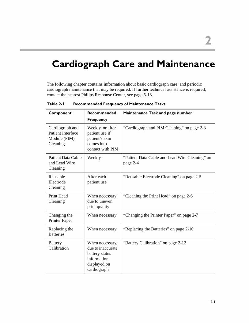
2
1Cardiograph Care and Maintenance
The following chapter contains information about basic cardiograph care, and periodic cardiograph maintenance that may be required. If further technical assistance is required, contact the nearest Philips Response Center, see page 5-13.
Table 2-1 Recommended Frequency of Maintenance Tasks
Component Recommended
Frequency
Maintenance Task and page number
Cardiograph and Patient Interface Module (PIM) Cleaning
Weekly, or after patient use if patient’s skin comes into contact with PIM
“Cardiograph and PIM Cleaning” on page 2-3
Patient Data Cable and Lead Wire Cleaning
Weekly “Patient Data Cable and Lead Wire Cleaning” on page 2-4
Reusable Electrode Cleaning
After each patient use
“Reusable Electrode Cleaning” on page 2-5
Print Head Cleaning
When necessary due to uneven print quality
“Cleaning the Print Head” on page 2-6
Changing the Printer Paper
When necessary “Changing the Printer Paper” on page 2-7
Replacing the Batteries
When necessary “Replacing the Batteries” on page 2-10
Battery Calibration
When necessary, due to inaccurate battery status information displayed on cardiograph
“Battery Calibration” on page 2-12
2-1
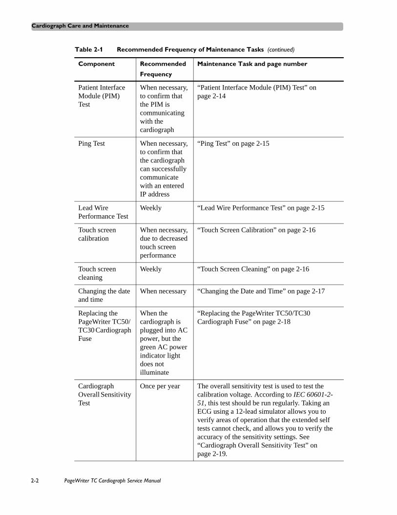
Cardiograph Care and Maintenance
Patient Interface Module (PIM) Test
When necessary, to confirm that the PIM is communicating with the cardiograph
“Patient Interface Module (PIM) Test” on page 2-14
Ping Test When necessary, to confirm that the cardiograph can successfully communicate with an entered IP address
“Ping Test” on page 2-15
Lead Wire Performance Test
Weekly “Lead Wire Performance Test” on page 2-15
Touch screen calibration
When necessary, due to decreased touch screen performance
“Touch Screen Calibration” on page 2-16
Touch screen cleaning
Weekly “Touch Screen Cleaning” on page 2-16
Changing the date and time
When necessary “Changing the Date and Time” on page 2-17
Replacing the PageWriter TC50/TC30 Cardiograph Fuse
When the cardiograph is plugged into AC power, but the green AC power indicator light does not illuminate
“Replacing the PageWriter TC50/TC30 Cardiograph Fuse” on page 2-18
Cardiograph Overall Sensitivity Test
Once per year The overall sensitivity test is used to test the calibration voltage. According to IEC 60601-2-51, this test should be run regularly. Taking an ECG using a 12-lead simulator allows you to verify areas of operation that the extended self tests cannot check, and allows you to verify the accuracy of the sensitivity settings. See “Cardiograph Overall Sensitivity Test” on page 2-19.
Table 2-1 Recommended Frequency of Maintenance Tasks (continued)
Component Recommended
Frequency
Maintenance Task and page number
2-2 PageWriter TC Cardiograph Service Manual

Cardiograph and PIM Cleaning Cardiograph Care and Maintenance
Cardiograph and PIM Cleaning
WARNING Electrical shock hazard. Keep the cardiograph, Patient Interface Module (PIM), and all cardiograph accessories away from liquids. Do not immerse the cardiograph, PIM, or other accessories in any liquids.
WARNING Always clean and disinfect the Patient Interface Module (PIM) after patient use, if the PIM comes into direct contact with the patient’s skin. Failure to properly clean and disinfect the PIM after direct contact with the patient’s skin may cause infectious materials to be transferred between patients.
To clean the cardiograph and PIM:
1 Unplug the AC power cord.
2 Ensure that the AC power indicator light (next to power button) is not lit.
3 Wipe the external surfaces of the cardiograph and the PIM with a soft cloth dampened in any of the approved cleaning solutions listed below.
CAUTION When cleaning, avoid the lead wire connectors and patient data cable connectors.
Approved Cleaning Solutions Mild soap and water
Isopropyl alcohol (consisting of 70% solution)
Chlorine bleach (5.25% sodium hypochlorite content) mixed as 3% solution in water
Quaternary ammonium compounds such as Steris Coverage Plus NPD, mixed as one half fluid ounce per gallon water, or one part Coverage Plus NPD to 256 parts water
CAUTIONS Do not use strong solvents or abrasive cleaning materials.
Do not use any of the following to clean the cardiograph:
Acetone
Iodine-based cleaners
Phenol-based cleaners
Ethylene oxide sterilization
Ammonia-based cleaners
The cardiograph, PIM, lead wires, and patient data cable should not be autoclaved, ultrasonically cleaned, or immersed.
PageWriter TC Cardiograph Service Manual 2-3

Cardiograph Care and Maintenance Patient Data Cable and Lead Wire Cleaning
Patient Data Cable and Lead Wire CleaningPrior to cleaning the patient data cable, inspect the patient data cable for any cracks or breaks in the cable insulation. If the integrity of the patient data cable is not assured, replace the patient data cable. Contact Philips Medical Systems for further assistance, see “Contacting a Philips Response Center” on page 5-13.
Approved Cleaning Solutions Mild soap and water
Isopropyl alcohol (consisting of 70% solution)
Chlorine bleach (5.25% sodium hypochlorite content) mixed as 3% solution in water
Quaternary ammonium compounds such as Steris Coverage Plus NPD, mixed as one half fluid ounce per gallon water, or one part Coverage Plus NPD to 256 parts water
CAUTIONS Do not use strong solvents or abrasive cleaning materials.
Do not use any of the following to clean the cardiograph:
Acetone
Iodine-based cleaners
Phenol-based cleaners
Ethylene oxide sterilization
Ammonia-based cleaners
The cardiograph, PIM, lead wires, and patient data cable should not be autoclaved, ultrasonically cleaned, or immersed.
To clean the patient data cable and lead wires:
1 Dampen a soft cloth with soapy water or with one of the disinfectants or cleaning agents listed in “Approved Cleaning Solutions” on page 2-4.
2 Wring excess moisture from the cloth before cleaning.
CAUTION Do not:
Autoclave the patient data cable or lead wires or use ultrasonic cleaners
Immerse
Use abrasive materials
Wet the connectors
2-4 PageWriter TC Cardiograph Service Manual

Reusable Electrode Cleaning Cardiograph Care and Maintenance
Reusable Electrode CleaningReusable limb clamp and Welsh Bulb electrodes must be cleaned after each use.
WARNING Always clean and disinfect reusable electrodes before patient use. Failure to properly clean and disinfect reusable electrodes before patient use may cause infectious materials to be transferred between patients.
Figure 2-1 Welsh Bulb and Limb Clamp Electrode
To clean reusable electrodes:
1 For Welsh Bulb electrodes only: detach the rubber bulb from the metal cup by pulling. Wash the rubber bulb in warm water. Remove all electrolyte gel residue, check inside the rubber bulb to ensure that all residue is removed.
2 For all reusable electrodes: dampen a soft cloth with one of the disinfectants or cleaning agents listed below.
Cidex Ortho Phthaladehyde
Cetylcide
Vesphene 2 Aqueous Phenolic Germicidal Agent
CAUTION Do not:
Use isopropyl alcohol
Autoclave the reusable electrodes or use ultrasonic cleaners
Use abrasive materials
3 Wring excess moisture from the cloth before cleaning.
4 Dry the bulb and cup of the Welsh Bulb electrode thoroughly before use.
5 Store the reusable electrodes away from direct sunlight and excessive heat when not in use.
PageWriter TC Cardiograph Service Manual 2-5
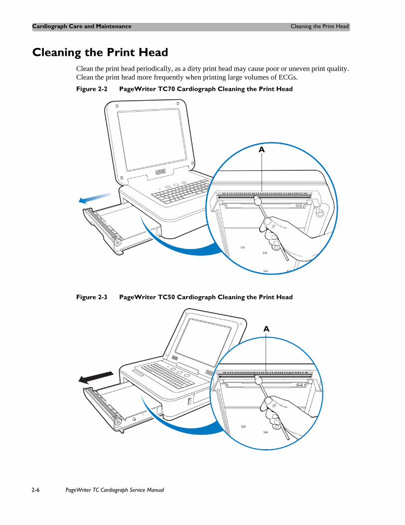
Cardiograph Care and Maintenance Cleaning the Print Head
Cleaning the Print Head Clean the print head periodically, as a dirty print head may cause poor or uneven print quality. Clean the print head more frequently when printing large volumes of ECGs.
Figure 2-2 PageWriter TC70 Cardiograph Cleaning the Print Head
Figure 2-3 PageWriter TC50 Cardiograph Cleaning the Print Head
A
A
2-6 PageWriter TC Cardiograph Service Manual

Changing the Printer Paper Cardiograph Care and Maintenance
Figure 2-4 PageWriter TC30 Cardiograph Cleaning the Print Head
To clean the print head:
1 Open the paper drawer.
2 Wipe the print head lightly with a foam swab dipped in 90% alcohol.
3 Allow the print head to dry.
Changing the Printer PaperReplace the printer paper when a red stripe appears on the printed ECG report. Only use Philips Medical Systems replacement printer paper. For part ordering information, see “Supplies and Ordering Information” on page 5-7.
To change the printer paper:
1 Open the paper drawer and remove any remaining sheets. Lift up the paper hold down bar.
A Print head
A
A Paper hold down bar
A
PageWriter TC Cardiograph Service Manual 2-7

Cardiograph Care and Maintenance Changing the Printer Paper
2 Insert a new pack of printer paper with the printed side facing up. Make sure that the hole for the paper sensor is positioned as shown below.
3 Drape the first sheet over the roller and place the paper hold down bar on top of the paper.
4 Close the paper drawer.
A Paper sensor hole
A Paper hold down bar
A
A
2-8 PageWriter TC Cardiograph Service Manual

Battery Maintenance and Care Cardiograph Care and Maintenance
Battery Maintenance and CareThe PageWriter TC70 cardiograph operates with two removable lithium ion batteries that supply power to the cardiograph during mobile use. The PageWriter TC50 and PageWriter TC30 cardiograph use either one or two removable lithium ion batteries that supply power to the cardiograph during mobile use.
For optimal battery performance:
When operating the PageWriter TC50 or PageWriter TC30 cardiograph with one battery installed, only use the Philips battery with part number 989803170371. Do not use the battery with Philips part number 989803160981 for one battery operation.
When operating any model of the PageWriter TC cardiograph with two batteries installed, ensure that both batteries contain the same Philips part number. The battery part number identification label is found on the bottom of the battery. The cardiograph cannot operate with two batteries that contain different part numbers. If the cardiograph is operated with two batteries with different part numbers, the cardiograph will display an error message. Before initial use, fully charge the batteries for five hours before operating the cardiograph without AC power. Regularly and consistently charging the batteries will prolong battery life.
Charging, storing, or using the batteries at temperatures above 50 oC (122o F) can damage the batteries and reduce overall battery life.
Check the battery power indicator on the Status Bar. Tap the battery icon on the Status Bar for information on remaining battery power, see Figure 1-18 on page 1-39.
Always charge the batteries when the cardiograph is not in use. Plug the cardiograph into AC power. Ensure that the green AC power indicator light on the front of the cardiograph is lit. The batteries will charge while the cardiograph is in use, but will charge at a slower rate.
Operate the cardiograph, charge the batteries, and store the batteries at a room temperature of 25 oC (77o F) or lower. Exposure to higher temperatures may reduce battery life, damage the batteries, and degrade overall cardiograph performance.
If the cardiograph will be stored for more than sixty days without use, fully charge the batteries, and after the batteries are fully charged remove AC power from the cardiograph, and then remove the batteries from the cardiograph. Store the batteries in a cool, dry location. A set of fully charged batteries stored outside the cardiograph will need to be recharged every sixty days.
PageWriter TC Cardiograph Service Manual 2-9

Cardiograph Care and Maintenance Battery Maintenance and Care
Replacing the Batteries
WARNING Properly dispose of or recycle depleted batteries according to local regulations. Do not disassemble, puncture, or incinerate the disposed batteries.
WARNING Carefully follow the instructions for replacing the batteries. Only use batteries with Philips part number 989803160981 or Philips part number 989803170371.
CAUTIONS Before removing and replacing batteries from the cardiograph, press down and hold the On/Standby button ( ) (located on the front of the cardiograph), to shut down the cardiograph. Ensure that the cardiograph is shut down. When the cardiograph is fully shut down, the screen is black, and the On/Standby button is not illuminated. Once the cardiograph is shut down, proceed to remove and replace the batteries.
When removing batteries from the cardiograph, the batteries could feel warm to the touch.
How often batteries need to be replaced depends on how well the battery is maintained and how much it is used. If the batteries are fully charged but lose significant power after only a few ECGs, consider replacement. For information on ordering replacement batteries, see “Supplies and Ordering Information” on page 5-7.
To install the batteries:
1 Press and hold the On/Standby button ( ) (located on the front of the cardiograph). Ensure that the cardiograph is shut down. When the cardiograph is fully shut down, the screen is black and the On/Standby button is not illuminated.
2 Unplug the cardiograph from AC power.
3 Open the battery door.
2-10 PageWriter TC Cardiograph Service Manual

Battery Maintenance and Care Cardiograph Care and Maintenance
4 Remove the batteries from the battery compartment by pulling on the gold straps.
5 Insert the replacement battery with the external connector facing the bottom rear of the compartment.
NOTE If operating the PageWriter TC50 or PageWriter TC30 cardiograph with one battery installed, the battery may be inserted into either battery compartment.
6 Ensure that the battery is fully inserted into the slot. The pull tab will insert along with the battery. Insert the second battery following the same procedure.
PageWriter TC Cardiograph Service Manual 2-11

Cardiograph Care and Maintenance Battery Calibration
7 Reinstall the battery door.
8 Connect the AC power cord to the cardiograph. Charge the batteries for five hours before operating the cardiograph on battery power only.
Battery CalibrationBattery calibration may be necessary in order to enhance the accuracy of the battery level indicator that displays on the Status Bar. If the accuracy of this indicator is affected, the other battery indicators included on the Battery Status window (that is opened by tapping the battery icon on the Status Bar) may also be less accurate.
2-12 PageWriter TC Cardiograph Service Manual

Battery Calibration Cardiograph Care and Maintenance
Figure 2-5 Battery Power Indicator on the Status Bar
The recommended intervals for battery calibration are dependent upon factors in your clinical use model. When the battery power indicators are not functioning so that they are useful in your daily work environment, Philips recommends calibrating the batteries following the procedure described in this section.
The battery calibration procedure requires that the cardiograph be taken out of active use for up to 8 hours.
To calibrate the batteries on the cardiograph:
1 Attach the AC power cord to the cardiograph. Ensure that the AC power supply is connected to a grounded electrical outlet and that the cardiograph is receiving AC power. Check that the AC power indicator light (located next to the On/Standby button) is lit.
2 Fully charge the batteries.
3 To ensure that the batteries are fully charged, view the Charge Current field in the Service Utility. Touch the Setup button on the toolbar. Select the Service Utility from the Configuration Setup and Service Utilities menu.
NOTE Accessing the Service Utility may require entering a password. If a password is lost and cannot be retrieved, contact the Philips Response Center for assistance (see page 5-13).
4 From the Service Utility screen, ensure that the About the Cardiograph button is selected (top of screen). A selected button is highlighted in blue.
5 Underneath the Battery Status column (middle of screen), check that the Charge Current field for both batteries display 0 mA, ensuring that both batteries are fully charged.
6 Touch the Print button (top of screen) to print out a report of the cardiograph settings displayed on this screen.
7 Touch the Exit button (lower right hand corner of screen). Touch the Exit button again on the Setup main menu.
8 Once the Main screen appears, touch the ID button to open the ID entry screen. Ensure that the ID screen remains open.
9 Unplug the cardiograph from AC power. Ensure that the AC power indicator light (located next to the On/Standby button) is not lit.
10 Keep the ID screen displayed and allow the batteries to deplete of all battery power. This process will take approximately 8 hours to complete. When the batteries are depleted of all power, the screen is black and the cardiograph cannot be returned to active use by touching the On/Standby button.
A Battery level indicator
A
PageWriter TC Cardiograph Service Manual 2-13

Cardiograph Care and Maintenance Patient Interface Module (PIM) Test
11 Once the batteries are fully depleted, reconnect the cardiograph to AC power. Press the On/Standby button to power on the cardiograph in order to confirm successful calibration. Afterwards, charge the batteries fully before returning the cardiograph to active use.
12 On the Main screen, touch the Setup button.
13 Select the Service Utility from the Configuration Setup and Service Utilities menu.
14 From the Service Utility screen, ensure that the About the Cardiograph button is selected (top of screen). A selected button is highlighted in blue.
15 Underneath the Battery Status column, check that the Expected Max Error (%) and Full Capacity (mAh) values as viewed on the screen are different than the values printed on the report generated from the Service Utility screen. If the values are different, the battery calibration procedure is complete.
NOTE If the Expected Max Error (%) field has not been reset to 2%, another calibration procedure may be necessary. The max error value may not change if the full charge capacity has been decreased by more than 256 mAh or increased by more than 512 mAh. If this occurs, another calibration procedure is recommended as soon as it is convenient to further improve the accuracy of displayed battery status information. For batteries with more than 8% of error, the maximum error will remain unchanged if a limited calibration cycle occurs.
Patient Interface Module (PIM) TestThis test is used to confirm that the Patient Interface Module (PIM) is communicating with the cardiograph. This test can be performed when the cardiograph displays PIM error messages, or when the cardiograph is unable to acquire data from the PIM. Be sure that the PIM patient data cable is securely attached to the PIM connector on the rear of the cardiograph before performing the test.
If this test fails, it may indicate a problem with the PIM or with the PIM patient data cable.
To perform the PIM Test:
1 Ensure that the patient data cable is securely attached to the PIM connector ( ) on the rear of the cardiograph. Ensure that the PIM disconnected icon ( ) does not appear on the Status Bar (top of screen).
2 Touch the Setup button on the bottom toolbar. The Configuration Setup and Service Utilities menu appears.
3 Touch Configure Cardiograph Default Settings. On the Default Cardiograph Settings screen, touch the Maintenance Test button (upper right side of screen).
4 The Maintenance Test screen appears. Touch the Patient Interface Module (PIM) Test button. The PIM test automatically starts and the results appear on the screen. The Patient Interface Module (PIM) Test window reports the PIM Option, the currently installed software PIM Kernel Version, and if the PIM Test has failed or passed. If the message PIM Test Passed appears, the PIM is communicating properly with the cardiograph.
5 Touch the Close button to close the window.
2-14 PageWriter TC Cardiograph Service Manual
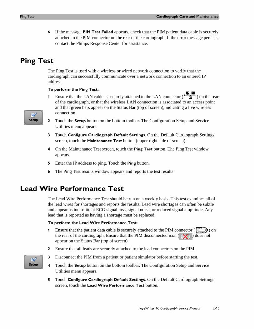
Ping Test Cardiograph Care and Maintenance
6 If the message PIM Test Failed appears, check that the PIM patient data cable is securely attached to the PIM connector on the rear of the cardiograph. If the error message persists, contact the Philips Response Center for assistance.
Ping TestThe Ping Test is used with a wireless or wired network connection to verify that the cardiograph can successfully communicate over a network connection to an entered IP address.
To perform the Ping Test:
1 Ensure that the LAN cable is securely attached to the LAN connector ( ) on the rear of the cardiograph, or that the wireless LAN connection is associated to an access point and that green bars appear on the Status Bar (top of screen), indicating a live wireless connection.
2 Touch the Setup button on the bottom toolbar. The Configuration Setup and Service Utilities menu appears.
3 Touch Configure Cardiograph Default Settings. On the Default Cardiograph Settings screen, touch the Maintenance Test button (upper right side of screen).
4 On the Maintenance Test screen, touch the Ping Test button. The Ping Test window appears.
5 Enter the IP address to ping. Touch the Ping button.
6 The Ping Test results window appears and reports the test results.
Lead Wire Performance Test The Lead Wire Performance Test should be run on a weekly basis. This test examines all of the lead wires for shortages and reports the results. Lead wire shortages can often be subtle and appear as intermittent ECG signal loss, signal noise, or reduced signal amplitude. Any lead that is reported as having a shortage must be replaced.
To perform the Lead Wire Performance Test:
1 Ensure that the patient data cable is securely attached to the PIM connector ( ) on the rear of the cardiograph. Ensure that the PIM disconnected icon ( ) does not appear on the Status Bar (top of screen).
2 Ensure that all leads are securely attached to the lead connectors on the PIM.
3 Disconnect the PIM from a patient or patient simulator before starting the test.
4 Touch the Setup button on the bottom toolbar. The Configuration Setup and Service Utilities menu appears.
5 Touch Configure Cardiograph Default Settings. On the Default Cardiograph Settings screen, touch the Lead Wire Performance Test button.
PageWriter TC Cardiograph Service Manual 2-15
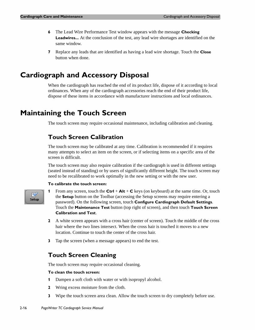
Cardiograph Care and Maintenance Cardiograph and Accessory Disposal
6 The Lead Wire Performance Test window appears with the message Checking Leadwires... At the conclusion of the test, any lead wire shortages are identified on the same window.
7 Replace any leads that are identified as having a lead wire shortage. Touch the Close button when done.
Cardiograph and Accessory DisposalWhen the cardiograph has reached the end of its product life, dispose of it according to local ordinances. When any of the cardiograph accessories reach the end of their product life, dispose of these items in accordance with manufacturer instructions and local ordinances.
Maintaining the Touch ScreenThe touch screen may require occasional maintenance, including calibration and cleaning.
Touch Screen CalibrationThe touch screen may be calibrated at any time. Calibration is recommended if it requires many attempts to select an item on the screen, or if selecting items on a specific area of the screen is difficult.
The touch screen may also require calibration if the cardiograph is used in different settings (seated instead of standing) or by users of significantly different height. The touch screen may need to be recalibrated to work optimally in the new setting or with the new user.
To calibrate the touch screen:
1 From any screen, touch the Ctrl + Alt + C keys (on keyboard) at the same time. Or, touch the Setup button on the Toolbar (accessing the Setup screens may require entering a password). On the following screen, touch Configure Cardiograph Default Settings. Touch the Maintenance Test button (top right of screen), and then touch Touch Screen Calibration and Test.
2 A white screen appears with a cross hair (center of screen). Touch the middle of the cross hair where the two lines intersect. When the cross hair is touched it moves to a new location. Continue to touch the center of the cross hair.
3 Tap the screen (when a message appears) to end the test.
Touch Screen CleaningThe touch screen may require occasional cleaning.
To clean the touch screen:
1 Dampen a soft cloth with water or with isopropyl alcohol.
2 Wring excess moisture from the cloth.
3 Wipe the touch screen area clean. Allow the touch screen to dry completely before use.
2-16 PageWriter TC Cardiograph Service Manual
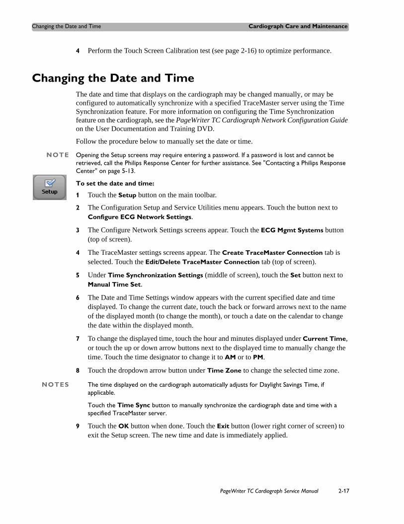
Changing the Date and Time Cardiograph Care and Maintenance
4 Perform the Touch Screen Calibration test (see page 2-16) to optimize performance.
Changing the Date and TimeThe date and time that displays on the cardiograph may be changed manually, or may be configured to automatically synchronize with a specified TraceMaster server using the Time Synchronization feature. For more information on configuring the Time Synchronization feature on the cardiograph, see the PageWriter TC Cardiograph Network Configuration Guide on the User Documentation and Training DVD.
Follow the procedure below to manually set the date or time.
NOTE Opening the Setup screens may require entering a password. If a password is lost and cannot be retrieved, call the Philips Response Center for further assistance. See "Contacting a Philips Response Center" on page 5-13.
To set the date and time:
1 Touch the Setup button on the main toolbar.
2 The Configuration Setup and Service Utilities menu appears. Touch the button next to Configure ECG Network Settings.
3 The Configure Network Settings screens appear. Touch the ECG Mgmt Systems button (top of screen).
4 The TraceMaster settings screens appear. The Create TraceMaster Connection tab is selected. Touch the Edit/Delete TraceMaster Connection tab (top of screen).
5 Under Time Synchronization Settings (middle of screen), touch the Set button next to Manual Time Set.
6 The Date and Time Settings window appears with the current specified date and time displayed. To change the current date, touch the back or forward arrows next to the name of the displayed month (to change the month), or touch a date on the calendar to change the date within the displayed month.
7 To change the displayed time, touch the hour and minutes displayed under Current Time, or touch the up or down arrow buttons next to the displayed time to manually change the time. Touch the time designator to change it to AM or to PM.
8 Touch the dropdown arrow button under Time Zone to change the selected time zone.
NOTES The time displayed on the cardiograph automatically adjusts for Daylight Savings Time, if applicable.
Touch the Time Sync button to manually synchronize the cardiograph date and time with a specified TraceMaster server.
9 Touch the OK button when done. Touch the Exit button (lower right corner of screen) to exit the Setup screen. The new time and date is immediately applied.
PageWriter TC Cardiograph Service Manual 2-17

Cardiograph Care and Maintenance Replacing the PageWriter TC50/TC30 Cardiograph Fuse
Replacing the PageWriter TC50/TC30 Cardiograph FuseThe AC fuse needs to be replaced when the cardiograph is plugged into AC power, but the green AC power indicator light does not illuminate.
NOTE The PageWriter TC70 cardiograph does not have a replaceable fuse.
Figure 2-6 AC power indicator light on TC50 or TC30 cardiograph
Only use replacement AC fuses with Philips part number 453564131221, or use a 1.6 amp (250V) time-delay fuse the same size and configuration as the original fuse.
Figure 2-7 Replacing the AC Fuse
To replace the AC fuse:
1 Unplug the cardiograph from AC power. Pull out the AC power cord from the AC power connector on the rear of the cardiograph.
2 Locate the AC fuse, which is directly below the AC power connector.
A AC power on indicator light
A AC fuse
A
A
2-18 PageWriter TC Cardiograph Service Manual

Cardiograph Overall Sensitivity Test Cardiograph Care and Maintenance
3 Push on both ends of the fuse and pull out the fuse from the fuse holder slot.
4 Insert the new fuse using the same orientation.
5 Push the fuse all the way into the fuse holder slot. The fuse snaps into place.
Cardiograph Overall Sensitivity TestThe overall sensitivity test is used to test the calibration voltage. According to IEC 60601-2-51, this test should be run regularly. Taking an ECG using a 12-lead simulator allows you to verify areas of operation that the extended self tests cannot check, and allows you to verify the accuracy of the sensitivity settings. This test should be run approximately once a year.
Before You BeginTo perform this test, you need an ECG simulator that is calibrated and is able to produce a 1mV 2 Hz square wave on Lead I or II. (The lead you use is dependent on the simulator.)
Performing the Sensitivity Test To perform the test:
1 Set the simulator to the 2Hz square wave setting and the amplitude to 1mV.
2 Ensure that the Simulated Waveform feature (cardiograph displays simulated patient ECG waveforms) is not enabled on the cardiograph.
3 Touch the Exam button on the Status Bar, and then touch the Resting 12-Lead button.
4 Touch the factory default Standard 12-lead Exam Profile button.
5 Touch the Settings button on the Status Bar.
a Set the Artifact filter to OFF.
b Set the Limb Leads setting to 10 mm/mV.
c Set the Speed setting to 25 mm/sec.
d Touch OK.
6 Touch the ECG button on the toolbar. If a message appears that no patient information has been entered, touch the Continue button. Depending on how the cardiograph is configured, the ECG may automatically print. If not, touch the Print button.
7 Verify Lead I or II for the following items on the printed report:
– The height of the ECG pulses for the sensitivity setting
– Measure the peak of the ECG pulse and calculate the voltage for the sensitivity setting
– Verify that the measured voltage value is 1mV. Count the boxes that are contained in the square wave from the top to the bottom, using the top left corner of the square wave labeled A in Figure 2-8 as the upper boundary, and the lower right corner of the
PageWriter TC Cardiograph Service Manual 2-19

Cardiograph Care and Maintenance Cardiograph and Accessory Disposal
square wave labeled B in Figure 2-8 as the lower boundary. The square wave should measure 10 mm (10 boxes) with a + 5% margin for error.
Figure 2-8 Overall Sensitivity Test Results
8 If the results fall outside of the + 5% range, run the test again. If you get the same results, try running the test on a different cardiograph. If the test fails on the other cardiograph, the simulator may be out of calibration. If the test passes on the other cardiograph, it may indicate a problem with your cardiograph. Contact the Philips Response Center for further assistance. See “Contacting a Philips Response Center” on page 5-13.
Cardiograph and Accessory DisposalWhen the cardiograph has reached the end of its product life, dispose of it according to local ordinances. When any of the cardiograph accessories reach the end of their product life, dispose of these items in accordance with manufacturer instructions and local ordinances.
A B
or
depending on simulator
2-20 PageWriter TC Cardiograph Service Manual
3
2 Troubleshooting
This chapter provides information for localizing cardiograph problems to the subassembly level. This information is designed for use with the cardiograph’s diagnostic self-tests to help you efficiently repair the cardiograph with a minimum of equipment.
The Philips Response Center can assist with product troubleshooting and provide technical expertise to help with any issue with the PageWriter TC cardiograph or any of its accessories. For a full listing of contact phone numbers, see “Contacting a Philips Response Center” on page 5-13.
This chapter provides the following information:Troubleshooting Cardiograph Issues . . . . . . . . . . . . . . . . . . . . . . . .3-2
Start up Issues . . . . . . . . . . . . . . . . . . . . . . . . . . . . . . . . . . . . . .3-2Display Issues . . . . . . . . . . . . . . . . . . . . . . . . . . . . . . . . . . . . . .3-3Keyboard Issues . . . . . . . . . . . . . . . . . . . . . . . . . . . . . . . . . . . .3-5Signal Acquisition Issues . . . . . . . . . . . . . . . . . . . . . . . . . . . . .3-7Main Screen Issues . . . . . . . . . . . . . . . . . . . . . . . . . . . . . . . . .3-10Archive Screen Issues . . . . . . . . . . . . . . . . . . . . . . . . . . . . . . .3-12Configuration Screen Issues . . . . . . . . . . . . . . . . . . . . . . . . . .3-18Printer Issues . . . . . . . . . . . . . . . . . . . . . . . . . . . . . . . . . . . . .3-21Compact Flash (CF) Card/USB Memory Stick Issues . . . . . .3-25TraceMaster ECG Management System Issues . . . . . . . . . . .3-28Orders Issues . . . . . . . . . . . . . . . . . . . . . . . . . . . . . . . . . . . . . .3-30Remote Query Issues . . . . . . . . . . . . . . . . . . . . . . . . . . . . . . .3-32Fax Issues . . . . . . . . . . . . . . . . . . . . . . . . . . . . . . . . . . . . . . . .3-34Log File and Custom Settings Issues . . . . . . . . . . . . . . . . . . .3-34Lead Map Troubleshooting . . . . . . . . . . . . . . . . . . . . . . . . . . .3-35Wireless Troubleshooting . . . . . . . . . . . . . . . . . . . . . . . . . . . .3-35
Restarting the Cardiograph . . . . . . . . . . . . . . . . . . . . . . . . . . . . . .3-37Using the Service Utilities . . . . . . . . . . . . . . . . . . . . . . . . . . . . . . .3-38
Using the About the Cardiograph Screen . . . . . . . . . . . . . . . .3-39Using the Diagnostic Tests and Utilities . . . . . . . . . . . . . . . . .3-42Using the Diagnostic Tests . . . . . . . . . . . . . . . . . . . . . . . . . . .3-45
Viewing and Saving Log Files . . . . . . . . . . . . . . . . . . . . . . . . . . . .3-50About Log Files. . . . . . . . . . . . . . . . . . . . . . . . . . . . . . . . . . . .3-50Saving Log Files . . . . . . . . . . . . . . . . . . . . . . . . . . . . . . . . . . .3-51
3-1

Troubleshooting Troubleshooting Cardiograph Issues
Troubleshooting Cardiograph IssuesThe troubleshooting information in this section will help you to localize a fault and to correct it.
The following charts list symptoms and the steps to follow to investigate and solve the problem. Several failure mode symptoms may actually be hardware induced or triggered, and may require board replacement or opening of the cardiograph for inspection, please contact the Philips Response Center for further assistance. See “Contacting a Philips Response Center” on page 5-13.
Start up Issues
Table 3-1 Start up Issues
Symptom Possible Cause & Investigation Step
Possible Solutions
Failed to implement custom settings. The cardiograph will automatically restart and restore current settings. Please contact the Philips Response Center for further assistance. message
Failure to load a configuration file
1 Restore the factory default settings.
2 Try loading the configuration file again.
3 If the problem persists, manually configure the cardiograph settings.
3-2 PageWriter TC Cardiograph Service Manual

Troubleshooting Cardiograph Issues Troubleshooting
Display Issues
Table 3-2 Display Issues
Symptom Possible Cause & Investigation Step
Solution
Screen is dark and shows no image
Cardiograph is in Standby.
Cardiograph battery capacity is below 15%.
1 Press the On/Standby button ( ). Confirm that the cardiograph can be returned to active use.
2 If the cardiograph does not restart, connect the cardiograph to AC power and then press the On/Standby button.
3 User training on proper use of Standby.
Power issue: AC Power
AC is applied but AC Power On indicator LED is dark.
1 Inspect AC power connections.
2 Ensure AC cord is not damaged and is plugged into appropriate live AC power socket.
3 Ensure that the power cord is is connected to the power input connector on the back of the cardiograph.
Power issue: Battery
AC is not attached and the battery is inserted into the cardiograph. Push the On/Standby button. The screen remains dark.
Cardiograph battery capacity is below 15%.
1 Open battery compartment door and inspect battery condition.
2 Ensure that the gold battery strap is fully extended before installing the battery.
3 Replace the batteries. See “Replacing the Batteries” on page 2-10.
PageWriter TC Cardiograph Service Manual 3-3

Troubleshooting Troubleshooting Cardiograph Issues
Display assembly failure Replace display. Contact the Philips Response Center for assistance. See “Contacting a Philips Response Center” on page 5-13.
Main board failure Replace Main board. Contact the Philips Response Center for assistance. See “Contacting a Philips Response Center” on page 5-13.
A dialog box shows software version information with a black background
File system is destroyed. 1 Wait 2 minutes and perform full software installation, see “Installing PageWriter TC Cardiograph Software and Enabling Tokens” on page 6-1.
2 Confirm successful software installation. See “Verifying the Software Installation” on page 6-7.
Table 3-2 Display Issues (continued)
Symptom Possible Cause & Investigation Step
Solution
3-4 PageWriter TC Cardiograph Service Manual

Troubleshooting Cardiograph Issues Troubleshooting
Keyboard Issues
Table 3-3 Keyboard Issues
Symptom Possible Cause & Investigation Step
Solution
Keyboard is unresponsive
Input focus loss
Keyboard controller subsystem has failed
1 Touch the cardiograph screen anywhere.
2 Restart cardiograph. See “Restarting the Cardiograph” on page 3-37.
3 Perform the Service Utility Keyboard/Hardware Key test on page 3-47.
4 If the test passes, try using the keyboard again.
5 If the test fails, replace the keyboard. Contact the Philips Response Center for assistance, see “Contacting a Philips Response Center” on page 5-13.
ID or ECG button on keyboard is unresponsive
Input focus loss Touch the cardiograph screen anywhere.
Keyboard is typing incorrect characters
Keyboard has Caps Lock feature enabled
1 Check to see if the Cap Lock icon ( ) appears on the Status Bar. See “The Status Bar” on page 1-51.
2 Turn off the Caps Lock feature.
3 User training on Caps Lock use.
Keyboard is typing incorrect characters
Incorrect keyboard option is installed
Contact the Philips Response Center for assistance, see “Contacting a Philips Response Center” on page 5-13.
PageWriter TC Cardiograph Service Manual 3-5

Troubleshooting Troubleshooting Cardiograph Issues
Keyboard is typing incorrect characters
The main board was recently replaced, and the procedure reset the cardiograph keyboard option to an incorrect setting.
1 If the main control board was recently replaced, perform a full installation of the cardiograph software using the Biomed Software Installation option in the software installation wizard. See “Installing the Software Upgrade” on page 6-3.
2 If the problem persists after a full software installation procedure, contact the Philips Response Center for further assistance. See “Contacting a Philips Response Center” on page 5-13.
Table 3-3 Keyboard Issues (continued)
Symptom Possible Cause & Investigation Step
Solution
3-6 PageWriter TC Cardiograph Service Manual

Troubleshooting Cardiograph Issues Troubleshooting
Signal Acquisition Issues Before attempting to troubleshoot a signal acquisition error as a mechanical issue, ensure that the following patient preparation and basic troubleshooting techniques have first been followed.
Always follow good skin and patient preparation techniques prior to taking an ECG. Proper skin preparation helps to ensure a good quality ECG. Skin is a poor conductor of electricity and frequently creates artifact that distorts the ECG signal.
To prepare the patient for an ECG:
1 Shave hair from electrode sites if necessary (excessive hair prevents a good connection).
2 Wash the skin thoroughly with soap and water.
3 Dry the skin vigorously to increase capillary blood flow to the tissues and to remove the dead, dry skin cells and oil.
NOTE Do not use alcohol to clean the skin because it dries the skin. If there is no time, rub the electrode sites with gauze to remove the dead, dry skin and to increase capillary flow.
4 Always use disposable electrodes, and ensure that the disposable electrodes have not expired. Place the electrodes on flat, fleshy parts of the arms and legs, and place all limb electrodes equal distance from the heart, at the same position on each limb. If a limb site is not available (amputation, injury) place the electrodes closer to the torso.
5 Ensure that all electrodes are firmly attached, and that the lead wires are not pulling on the electrodes. If the electrodes can be moved easily, the electrode connection is too loose.
6 Reassure the patient and make sure that the patient is comfortable. If the patient has tremors, attach the limb electrodes higher on the patient (closer to the torso), and assist with limiting patient moving while taking the ECG.
After ensuring that proper patient preparation techniques are being followed, and that fresh electrodes are being applied to the patient, review the following table for further assistance.
PageWriter TC Cardiograph Service Manual 3-7
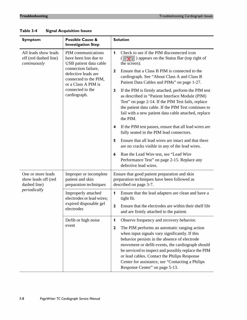
Troubleshooting Troubleshooting Cardiograph Issues
Table 3-4 Signal Acquisition Issues
Symptom Possible Cause & Investigation Step
Solution
All leads show leads off (red dashed line) continuously
PIM communications have been lost due to USB patient data cable connection failure, defective leads are connected to the PIM, or a Class A PIM is connected to the cardiograph.
1 Check to see if the PIM disconnected icon ( ) appears on the Status Bar (top right of the screen).
2 Ensure that a Class B PIM is connected to the cardiograph. See “About Class A and Class B Patient Data Cables and PIMs” on page 1-27.
3 If the PIM is firmly attached, perform the PIM test as described in “Patient Interface Module (PIM) Test” on page 2-14. If the PIM Test fails, replace the patient data cable. If the PIM Test continues to fail with a new patient data cable attached, replace the PIM.
4 If the PIM test passes, ensure that all lead wires are fully seated in the PIM lead connectors.
5 Ensure that all lead wires are intact and that there are no cracks visible in any of the lead wires.
6 Run the Lead Wire test, see “Lead Wire Performance Test” on page 2-15. Replace any defective lead wires.
One or more leads show leads off (red dashed line) periodically
Improper or incomplete patient and skin preparation techniques
Ensure that good patient preparation and skin preparation techniques have been followed as described on page 3-7.
Improperly attached electrodes or lead wires; expired disposable gel electrodes
1 Ensure that the lead adapters are clean and have a tight fit.
2 Ensure that the electrodes are within their shelf life and are firmly attached to the patient.
Defib or high noise event
1 Observe frequency and recovery behavior.
2 The PIM performs an automatic ranging action when input signals vary significantly. If this behavior persists in the absence of electrode movement or defib events, the cardiograph should be serviced to inspect and possibly replace the PIM or lead cables. Contact the Philips Response Center for assistance, see “Contacting a Philips Response Center” on page 5-13.
3-8 PageWriter TC Cardiograph Service Manual

Troubleshooting Cardiograph Issues Troubleshooting
PIM reset (up to ten second duration)
It is normal for the PIM to reset under the following conditions:
power on/wakeup
screen changes
insertion/removal of a USB device (USB memory stick)
Electrostatic discharge
When the PIM resets, it is normal for all leads to display as red dashed lines for up to ten seconds and for the PIM disconnected icon ( ) to appear on the Status Bar (top of screen).
One or more leads show leads off (red dashed line) periodically
PIM communications have been lost due to USB patient data cable connection failure, or defective leads are connected to the PIM.
1 Check to see if the PIM disconnected icon ( ) appears on the Status Bar (top of screen).
2 If the PIM is firmly attached, perform the PIM test as described in “Patient Interface Module (PIM) Test” on page 3-45. If the PIM Test fails, replace the patient data cable. If the PIM Test continues to fail with a new patient data cable attached, replace the PIM.
3 If the PIM test passes, ensure that all lead wires are fully seated in the PIM lead connectors.
4 Ensure that all lead wires are intact and that there are no visible cracks in the lead wires.
5 Run the lead wire test, see page 2-15.
6 Replace any of the leads that fail the lead wire test.
Patient Interface Module (PIM) not detected message or PIM disconnected icon ( ) appears on screen
PIM not connected
Faulty patient data cable
Faulty PIM
Class A PIM is connected to the cardiograph
1 Check that a Class B PIM is connected to the cardiograph, see “About Class A and Class B Patient Data Cables and PIMs” on page 1-27.
2 Check that PIM patient data cable is firmly seated to the PIM connector ( ) on the rear of the cardiograph.
3 If the PIM is firmly attached, perform the PIM test as described in “Patient Interface Module (PIM) Test” on page 2-14. If the PIM Test fails, replace the patient data cable.
Table 3-4 Signal Acquisition Issues (continued)
Symptom Possible Cause & Investigation Step
Solution
PageWriter TC Cardiograph Service Manual 3-9

Troubleshooting Troubleshooting Cardiograph Issues
Main Screen Issues
Table 3-5 Main Screen Issues
Symptom Possible Cause & Investigation Step
Solution
Incorrect language appears on cardiograph software
The main board was recently replaced, and the procedure reset the cardiograph software localization (language) option to an incorrect setting.
1 If the main control board was recently replaced, perform a full installation of the cardiograph software using the Biomed Software Installation option in the software installation wizard. See “Installing the Software Upgrade” on page 6-3.
2 If the problem persists after a full software installation procedure, contact the Philips Response Center for further assistance. See “Contacting a Philips Response Center” on page 5-13.
Waveform display is no longer updating, system is unresponsive
Software is frozen 1 Restart the cardiograph. See “Restarting the Cardiograph” on page 3-37.
2 Export the log file. See “Viewing and Saving Log Files” on page 3-50.
3 Report the software issue to the nearest Philips Response Center, see “Contacting a Philips Response Center” on page 5-13.
Waveform display is no longer updating, system is unresponsive
Main board failure 1 Restart the cardiograph. See “Restarting the Cardiograph” on page 3-37.
2 If this fails, remove and replace the main board. Contact the nearest Philips Response Center for further assistance, see “Contacting a Philips Response Center” on page 5-13.
Invalid Report Handle message
Report handle is invalid when preview, printing, saving ECGs.
1 Restart the cardiograph. See “Restarting the Cardiograph” on page 3-37.
2 Wait 2 minutes and perform full software installation. See “Installing the Software Upgrade” on page 6-3.
3 Confirm successful software installation. See “Verifying the Software Installation” on page 6-7.
3-10 PageWriter TC Cardiograph Service Manual

Troubleshooting Cardiograph Issues Troubleshooting
No Report message The software can't map the input report handle to the internal report object. The handle is invalid.
1 Restart the cardiograph. See “Restarting the Cardiograph” on page 3-37.
2 Wait 2 minutes and perform full software installation. See “Installing the Software Upgrade” on page 6-3.
3 Confirm successful software installation. See “Verifying the Software Installation” on page 6-7.
Internal function error message
Invalid file or the file resides on unsupported media.
1 Restart the cardiograph. See “Restarting the Cardiograph” on page 3-37.
2 Wait 2 minutes and perform full software installation. See “Installing the Software Upgrade” on page 6-3.
3 Confirm successful software installation. See “Verifying the Software Installation” on page 6-7.
Table 3-5 Main Screen Issues (continued)
Symptom Possible Cause & Investigation Step
Solution
PageWriter TC Cardiograph Service Manual 3-11

Troubleshooting Troubleshooting Cardiograph Issues
Archive Screen Issues
Table 3-6 Archive Screen Issues
Symptom Possible Cause & Investigation Step
Solution
Command timed-out message
The TraceMaster ECG Management system is busy.
Retry TraceMaster operation.
Transfer operations use network and server resources, which may occasionally be unable to service the requests.
ECGs with incomplete required patient information fields cannot be transferred message
The required information for the ECG has not been entered.
Enter the required ECG information and try the archive operation again. For more information see Chapter 3 “The Patient Session” of the PageWriter TC Cardiograph Instructions for Use.
Selected ECG(s) exceeds available space on TraceMaster Remote site message
The TraceMaster system is out of available disk space.
Contact the TraceMaster system administrator and report the error.
3-12 PageWriter TC Cardiograph Service Manual
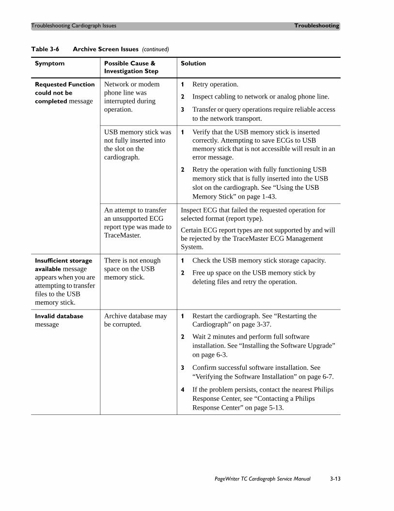
Troubleshooting Cardiograph Issues Troubleshooting
Requested Function could not be completed message
Network or modem phone line was interrupted during operation.
1 Retry operation.
2 Inspect cabling to network or analog phone line.
3 Transfer or query operations require reliable access to the network transport.
USB memory stick was not fully inserted into the slot on the cardiograph.
1 Verify that the USB memory stick is inserted correctly. Attempting to save ECGs to USB memory stick that is not accessible will result in an error message.
2 Retry the operation with fully functioning USB memory stick that is fully inserted into the USB slot on the cardiograph. See “Using the USB Memory Stick” on page 1-43.
An attempt to transfer an unsupported ECG report type was made to TraceMaster.
Inspect ECG that failed the requested operation for selected format (report type).
Certain ECG report types are not supported by and will be rejected by the TraceMaster ECG Management System.
Insufficient storage available message appears when you are attempting to transfer files to the USB memory stick.
There is not enough space on the USB memory stick.
1 Check the USB memory stick storage capacity.
2 Free up space on the USB memory stick by deleting files and retry the operation.
Invalid database message
Archive database may be corrupted.
1 Restart the cardiograph. See “Restarting the Cardiograph” on page 3-37.
2 Wait 2 minutes and perform full software installation. See “Installing the Software Upgrade” on page 6-3.
3 Confirm successful software installation. See “Verifying the Software Installation” on page 6-7.
4 If the problem persists, contact the nearest Philips Response Center, see “Contacting a Philips Response Center” on page 5-13.
Table 3-6 Archive Screen Issues (continued)
Symptom Possible Cause & Investigation Step
Solution
PageWriter TC Cardiograph Service Manual 3-13

Troubleshooting Troubleshooting Cardiograph Issues
When an error occurs during transfer of multiple ECGs to a TraceMaster system, the transfer process does not continue and transferred files are not deleted.
Application limitation The PageWriter TC cardiograph ECG transfer operations fail in a known safe manner when multiple ECG transfer operations are interrupted.
Retry the transfer for the remaining ECGs.
After pressing the Archive button, it takes longer than 40 seconds before the Archive list is displayed when the Main Archive has more than 130 ECGs stored.
System slow-down from full ECG database
Save or delete ECGs from the Main Archive.
There is a known system performance impact when the near maximum number of ECGs have been stored in the Main Archive.
Transfer of ECGs to a USB memory stick fails and there are still less than 200 ECGs on the removable media device.
USB memory stick file system limitation
Not enough free space available on the USB memory stick to save the number of selected ECGs
Delete unwanted files from the USB memory stick.
No reply received from TraceMaster Remote site message
The server is unavailable
Configuration error
1 Contact the TraceMaster system administrator and report the error.
2 Check the IP address and the TraceMaster server URL in the TraceMaster configuration settings.
Archive function could not be completed. Please restart cardiograph and try again. message
Archive error 1 Restart the cardiograph. See “Restarting the Cardiograph” on page 3-37.
2 If the problem persists, save the log files. See “Viewing and Saving Log Files” on page 3-50.
3 Contact the nearest Philips Response Center for further assistance.
Table 3-6 Archive Screen Issues (continued)
Symptom Possible Cause & Investigation Step
Solution
3-14 PageWriter TC Cardiograph Service Manual

Troubleshooting Cardiograph Issues Troubleshooting
Archive process was terminated due to an error message
Archive error 1 Restart the cardiograph. See “Restarting the Cardiograph” on page 3-37.
2 If the problem persists, save the log files. See “Viewing and Saving Log Files” on page 3-50.
3 Contact the nearest Philips Response Center for further assistance.
Bad reply received from TraceMaster Remote site message
Archive error, bad reply from server
1 Restart the cardiograph. See “Restarting the Cardiograph” on page 3-37.
2 Contact the TraceMaster system administrator and report the error.
Unexpected reply received from TraceMaster Remote Site message
Archive error, unexpected reply from server
1 Restart the cardiograph. See “Restarting the Cardiograph” on page 3-37.
2 Contact the TraceMaster system administrator and report the error.
Invalid XML schema version message
Archive error, unsupported XML schema
Restart the cardiograph. See “Restarting the Cardiograph” on page 3-37.
Unsupported XML version message
XML schema of selected ECG is not supported by TraceMaster server.
Check the TraceMaster/ECG Management System configuration settings screens to ensure that the correct TraceMaster server version is selected.
XML error message XML ECG file corrupted
1 Restart the cardiograph. See “Restarting the Cardiograph” on page 3-37.
2 If the problem persists, save the log files. See “Viewing and Saving Log Files” on page 3-50.
3 Contact the nearest Philips Response Center for further assistance.
Table 3-6 Archive Screen Issues (continued)
Symptom Possible Cause & Investigation Step
Solution
PageWriter TC Cardiograph Service Manual 3-15

Troubleshooting Troubleshooting Cardiograph Issues
XML unicode encoding is not UTF-16 message
Invalid encoding 1 Restart the cardiograph. See “Restarting the Cardiograph” on page 3-37.
2 If the problem persists, save the log files. See “Viewing and Saving Log Files” on page 3-50.
3 Contact the nearest Philips Response Center for further assistance.
Error accessing external XML file message
File I/O error 1 Restart the cardiograph. See “Restarting the Cardiograph” on page 3-37.
2 If the problem persists, save the log files. See “Viewing and Saving Log Files” on page 3-50.
3 Contact the nearest Philips Response Center for further assistance.
Error XML file is too large message
File is too large 1 Restart the cardiograph. See “Restarting the Cardiograph” on page 3-37.
2 If the problem persists, save the log files. See “Viewing and Saving Log Files” on page 3-50.
3 Contact the nearest Philips Response Center for further assistance.
Error XML file did not transform message
File I/O error 1 Restart the cardiograph. See “Restarting the Cardiograph” on page 3-37.
2 If the problem persists, save the log files. See “Viewing and Saving Log Files” on page 3-50.
3 Contact the nearest Philips Response Center for further assistance.
Fax transmission did not complete message
Fax not completed 1 Retry the fax operation.
2 If the problem persists, save the log files. See “Viewing and Saving Log Files” on page 3-50.
3 Contact the nearest Philips Response Center for further assistance.
There is no default TraceMaster server available for Auto Time Sync message
TraceMaster settings are not configured correctly.
1 Check the TraceMaster configuration settings on the cardiograph.
2 Touch the Setup button on the main toolbar to access the TraceMaster settings screen.
Table 3-6 Archive Screen Issues (continued)
Symptom Possible Cause & Investigation Step
Solution
3-16 PageWriter TC Cardiograph Service Manual
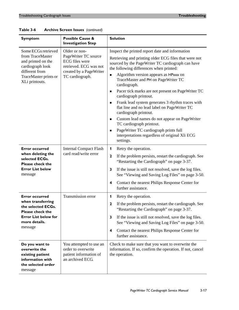
Troubleshooting Cardiograph Issues Troubleshooting
Some ECGs retrieved from TraceMaster and printed on the cardiograph look different from TraceMaster prints or XLi printouts.
Older or non-PageWriter TC source ECG files were retrieved. ECG was not created by a PageWriter TC cardiograph.
Inspect the printed report date and information
Retrieving and printing older ECG files that were not sourced by the PageWriter TC cardiograph can have the following differences when printed:
Algorithm version appears as HPxxx on TraceMaster and PH on PageWriter TC cardiograph.
Pacer tick marks are not present on PageWriter TC cardiograph printout.
Frank lead system generates 3 rhythm traces with flat line and no lead label on PageWriter TC cardiograph printout.
Custom lead names do not appear on PageWriter TC cardiograph printout.
PageWriter TC cardiograph prints full interpretations regardless of original Xli ECG settings.
Error occurred when deleting the selected ECGs. Please check the Error List below message
Internal Compact Flash card read/write error
1 Retry the operation.
2 If the problem persists, restart the cardiograph. See “Restarting the Cardiograph” on page 3-37.
3 If the issue is still not resolved, save the log files. See “Viewing and Saving Log Files” on page 3-50.
4 Contact the nearest Philips Response Center for further assistance.
Error occurred when transferring the selected ECGs. Please check the Error List below for more details. message
Transmission error 1 Retry the operation.
2 If the problem persists, restart the cardiograph. See “Restarting the Cardiograph” on page 3-37.
3 If the issue is still not resolved, save the log files. See “Viewing and Saving Log Files” on page 3-50.
4 Contact the nearest Philips Response Center for further assistance.
Do you want to overwrite the existing patient information with the selected order message
You attempted to use an order to overwrite patient information of an archived ECG.
Check to make sure that you want to overwrite the information. If so, confirm the operation. If not, cancel the operation.
Table 3-6 Archive Screen Issues (continued)
Symptom Possible Cause & Investigation Step
Solution
PageWriter TC Cardiograph Service Manual 3-17

Troubleshooting Troubleshooting Cardiograph Issues
Configuration Screen Issues
Table 3-7 Configuration Screen Issues
Symptom Possible Cause & Investigation Step
Solution
The maximum number of TraceMaster connections has been configured. Please edit or delete an existing TraceMaster connection. message
There are a limited number of TraceMaster connections that can be configured on the cardiograph.
Remove one of the TraceMaster connections.
The maximum number of OrderVue inboxes has been created. Edit or delete an existing inbox. message
There are a limited number of OrderVue inboxes that can be configured on the cardiograph.
Remove one of the OrderVue inboxes.
Invalid XML version detected. Please try again. message
Invalid version detected when loading configuration file.
If the problem persists, manually configure the cardiograph settings.
Invalid XML platform detected. Please try again. message
Invalid platform detected when loading configuration file.
If the problem persists, manually configure the cardiograph settings.
Invalid XML file detected. Please try again. message
Invalid configuration file detected when loading configuration file.
1 Ensure you are selecting a configuration file.
2 If the problem persists, manually configure the cardiograph settings.
Failed to implement custom settings. The cardiograph will automatically restart and restore custom settings. message
Corrupted configuration file detected when loading configuration file.
1 Cardiograph automatically restarts and loads current configuration.
2 If the problem persists, manually configure the cardiograph settings.
Duplicate Profile name. Please enter a unique name. message
You attempted to save an exam profile under an existing name.
Choose another name and save the exam profile.
3-18 PageWriter TC Cardiograph Service Manual

Troubleshooting Cardiograph Issues Troubleshooting
Password is missing. Please re-enter your password before continuing. message
The Configuration screen is password protected and you did not enter a password.
Enter the correct password to gain access to the configuration screens.
Password is not confirmed. Confirm your password before proceeding. message
You enabled the Configuration password but did not confirm it.
Confirm the configuration password after entering it.
The maximum number of fax profiles has been configured. Please edit or delete an existing fax profile. message
There is a current system limitation of one fax profile.
Edit or delete an existing fax profile.
Please select a TraceMaster server as the default connection message
You attempted to set a default TraceMaster server without first selecting it.
You must first select a TraceMaster server before it can be set as the default.
The cardiograph must restart in order to display simulated waveform data message
The cardiograph’s simulation mode was turned on and the device must be restarted to display simulated waveform data.
Touch OK to restart the cardiograph.
The cardiograph must restart in order to return to normal operating mode message
The cardiograph’s simulation mode was turned off and the device must be restarted to return to normal operation mode.
Touch OK to restart the cardiograph.
Unsaved changes will be deleted. Do you want to continue and discard changes? message
After making a configuration change, you touched the Exit button without saving the change.
Save any configuration changes before exiting the configuration screens.
Table 3-7 Configuration Screen Issues (continued)
Symptom Possible Cause & Investigation Step
Solution
PageWriter TC Cardiograph Service Manual 3-19

Troubleshooting Troubleshooting Cardiograph Issues
Invalid name. Please save again with a different name. message
You attempted to create a TraceMaster server or a fax recipient without entering a name.
Check the TraceMaster and Fax configuration settings and enter a valid name.
This TraceMaster server name is already in use. Please enter a different name. message
You attempted to configure a TraceMaster server name that is already in use.
Check the TraceMaster configuration settings and specify another server name.
Please enable Admin Password before enabling this password message
You attempted to enable an Archive, Configuration, or Service password without first enabling as Admin password.
1 Configure an Admin password first.
2 Configure the other passwords.
Please disable all user passwords before disabling this one message
You attempted to disable the Admin password without first disabling the Archive, Configuration, or Service password.
1 Disable the Admin password first.
2 Disable the other passwords.
The number of minutes set for ‘Shut Down’ must be greater than the number of minutes set for ‘Standby’ message
You attempted to configure the shut down time to be less than the Standby time.
Configure the Shut down time to be greater than the Standby time.
Table 3-7 Configuration Screen Issues (continued)
Symptom Possible Cause & Investigation Step
Solution
3-20 PageWriter TC Cardiograph Service Manual

Troubleshooting Cardiograph Issues Troubleshooting
Printer Issues
Table 3-8 Printer Issues
Symptom Possible Cause & Investigation Step Solution
The message Busy appears after you have sent a job to the printer.
A new print job has been sent to the printer and the printer cannot accept a new print job.
Restart the cardiograph. See “Restarting the Cardiograph” on page 3-37.
The message USB appears when attempting to print a rhythm strip.
A new print job has been sent to the printer and the printer cannot accept a new print job.
Restart the cardiograph. See “Restarting the Cardiograph” on page 3-37.
Printing is disabled with one battery only, please check the battery message (PageWriter TC70 cardiograph only)
The PageWriter TC70 cardiograph must operate with two batteries at all times.
Insert the second battery.
Low battery warning: printing is disabled. Connect the cardiograph to AC power and recharge the batteries message appears after you have sent a job to the printer.
No battery or dead battery Plug the cardiograph into AC power or replace the battery.
Field Programmable Gate Array (FPGA) communication is incorrectly configured. Please contact the Philips Response Center for further assistance. message
Internal error 1 Restart the cardiograph. See “Restarting the Cardiograph” on page 3-37.
2 If the problem persists, replace the main control board. Contact the nearest Philips Response Center for further assistance, see “Contacting a Philips Response Center” on page 5-13.
PageWriter TC Cardiograph Service Manual 3-21

Troubleshooting Troubleshooting Cardiograph Issues
Field Programmable Gate Array (FPGA) is not connected. Please contact the Philips Response Center for further assistance. message.
Internal error 1 Restart the cardiograph. See “Restarting the Cardiograph” on page 3-37.
2 If the problem persists, replace the main control board. Contact the nearest Philips Response Center for further assistance, see “Contacting a Philips Response Center” on page 5-13.
Printer temperature is too high message
The temperature of the print head is too high.
Shut down cardiograph and wait 20 minutes.
Printer underflow. message
Intermittent PIM communication issues during rhythm printing
Follow the steps in “Signal Acquisition Issues” on page 3-7 for PIM signal acquisition issues.
Printer voltage high message.
Printer supply voltage on main board is outside of expected ranges on the high side.
1 Restart the cardiograph. See “Restarting the Cardiograph” on page 3-37.
2 If the problem persists, replace the main control board. Contact the nearest Philips Response Center for further assistance, see “Contacting a Philips Response Center” on page 5-13.
Printer voltage low message
Printer supply voltage on main board is outside of expected ranges on the low side.
1 Restart the cardiograph. See “Restarting the Cardiograph” on page 3-37.
2 If the problem persists, replace the main control board. Contact the nearest Philips Response Center for further assistance, see “Contacting a Philips Response Center” on page 5-13.
Printer Door is Open message
Printer door is open. 1 Close the printer door.
2 Restart the cardiograph. See “Restarting the Cardiograph” on page 3-37.
Table 3-8 Printer Issues (continued)
Symptom Possible Cause & Investigation Step Solution
3-22 PageWriter TC Cardiograph Service Manual

Troubleshooting Cardiograph Issues Troubleshooting
Check Printer message appears with no apparent printer problem present.
Printer controller error
Printer cable inside cardiograph has become dislodged.
1 Open and close printer paper drawer. Message does not reoccur.
2 If message persists, replace the print head assembly. Contact the nearest Philips Response Center for assistance, see “Contacting a Philips Response Center” on page 5-13.
Printed report looks too small or compressed.
Printer controller error 1 Run the Printer Test from the Service Utilities on page 3-43.
2 If test passes, retry print operation.
3 If test fails, restart the cardiograph. See “Restarting the Cardiograph” on page 3-37.
4 If the problem persists, replace the print head assembly. Contact the nearest Philips Response Center for assistance, see “Contacting a Philips Response Center” on page 5-13.
After opening and closing the paper drawer rapidly many times, the cardiograph was unresponsive.
Printer controller error 1 Restart the cardiograph. See “Restarting the Cardiograph” on page 3-37.
Cardiograph restarts and boots correctly. Reports print correctly.
2 If the problem persists, replace the print head assembly. Contact the nearest Philips Response Center for assistance, see “Contacting a Philips Response Center” on page 5-13.
Table 3-8 Printer Issues (continued)
Symptom Possible Cause & Investigation Step Solution
PageWriter TC Cardiograph Service Manual 3-23

Troubleshooting Troubleshooting Cardiograph Issues
Printer Error: Out of Paper/Paper Jam/Door Open messages
Paper drawer is not fully closed
Out of paper, or paper loaded incorrectly with top-of-form hole on wrong side
Incompatible paper loaded
Defective paper tray assembly
Top-of-form sensor or door closed sensor issue
1 Make sure paper drawer is fully closed.
2 Reload the paper. Confirm that paper is loaded correctly.
3 Confirm that the paper is compatible with the Philips approved paper (see Ordering Supplies in Chapter 4).
4 Replace the paper tray assembly.
5 If the sensors are bad, replace the print head assembly. Contact the nearest Philips Response Center for assistance, see “Contacting a Philips Response Center” on page 5-13.
Printer not detected message
Application error
Defective print head assembly
1 Restart the cardiograph. See “Restarting the Cardiograph” on page 3-37.
2 Replace the print head assembly. Contact the nearest Philips Response Center for assistance, see “Contacting a Philips Response Center” on page 5-13.
Paper does not advance
Application error
Top-of-form sensor issue
Defective print head assembly
1 Restart the cardiograph. See “Restarting the Cardiograph” on page 3-37.
2 Replace the paper tray assembly.
3 If the sensors are bad, replace the print head assembly. Contact the nearest Philips Response Center for assistance, see “Contacting a Philips Response Center” on page 5-13.
Paper does not tear off cleanly, or paper stops at the wrong spot
Wrong paper size setting
Wrong method is being used to tear off paper
Reload printer with correct paper size. See “Changing the Printer Paper” on page 2-7.
Blank pages printed after ECG report
Wrong paper size setting Reload printer with correct paper size. See “Changing the Printer Paper” on page 2-7.
Table 3-8 Printer Issues (continued)
Symptom Possible Cause & Investigation Step Solution
3-24 PageWriter TC Cardiograph Service Manual
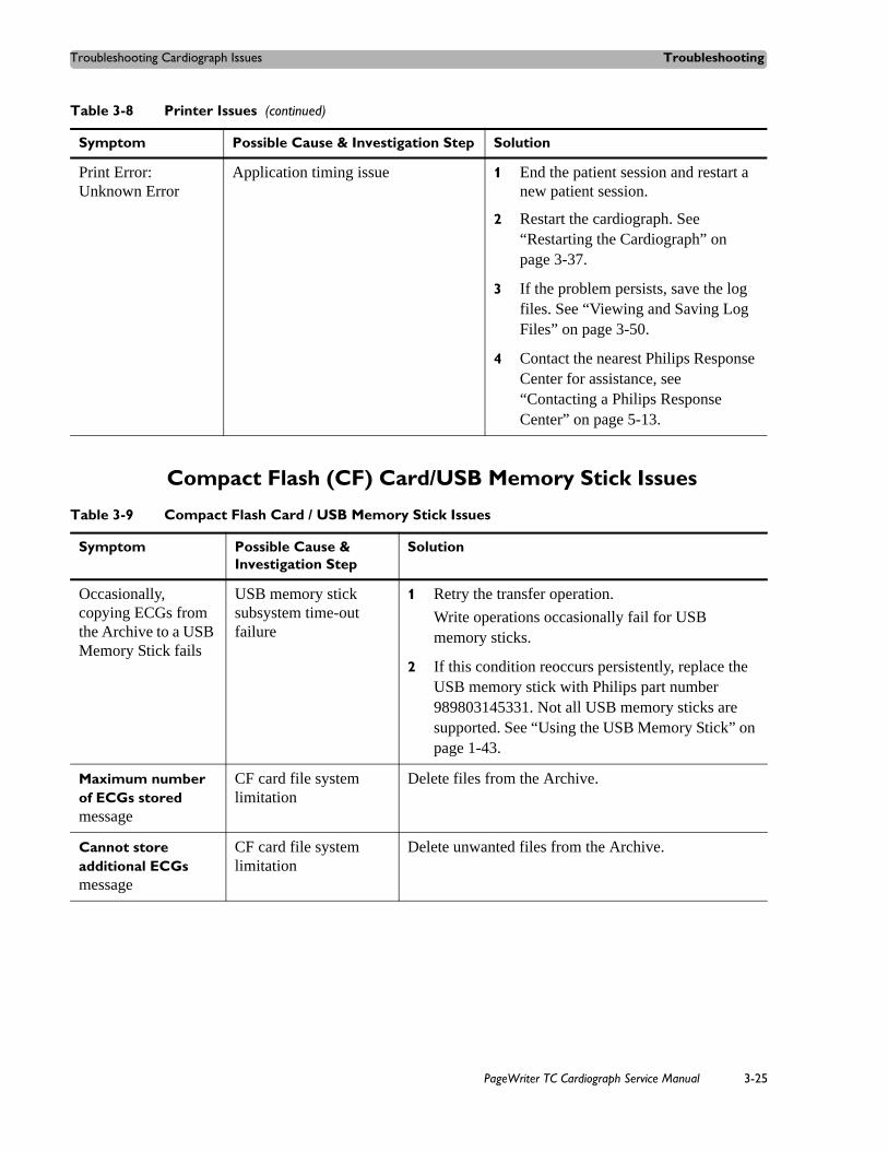
Troubleshooting Cardiograph Issues Troubleshooting
Compact Flash (CF) Card/USB Memory Stick Issues
Print Error: Unknown Error
Application timing issue 1 End the patient session and restart a new patient session.
2 Restart the cardiograph. See “Restarting the Cardiograph” on page 3-37.
3 If the problem persists, save the log files. See “Viewing and Saving Log Files” on page 3-50.
4 Contact the nearest Philips Response Center for assistance, see “Contacting a Philips Response Center” on page 5-13.
Table 3-8 Printer Issues (continued)
Symptom Possible Cause & Investigation Step Solution
Table 3-9 Compact Flash Card / USB Memory Stick Issues
Symptom Possible Cause & Investigation Step
Solution
Occasionally, copying ECGs from the Archive to a USB Memory Stick fails
USB memory stick subsystem time-out failure
1 Retry the transfer operation.
Write operations occasionally fail for USB memory sticks.
2 If this condition reoccurs persistently, replace the USB memory stick with Philips part number 989803145331. Not all USB memory sticks are supported. See “Using the USB Memory Stick” on page 1-43.
Maximum number of ECGs stored message
CF card file system limitation
Delete files from the Archive.
Cannot store additional ECGs message
CF card file system limitation
Delete unwanted files from the Archive.
PageWriter TC Cardiograph Service Manual 3-25

Troubleshooting Troubleshooting Cardiograph Issues
Cannot access internal Compact Flash memory message
Compact Flash may be corrupted.
1 Run the Internal Compact Flash test from the Service Utilities on page 3-47.
2 If the test passes, retry the operation.
3 If the test fails, the Compact Flash card needs to be removed and replaced. Contact the nearest Philips Response Center for assistance, see “Contacting a Philips Response Center” on page 5-13.
There are more than 200 ECGs stored on the USB memory stick. Only the first 200 ECGs will display on the cardiograph. Please store no more than 200 ECGs on the USB memory stick. message
USB memory stick file system limitation
Delete unwanted files from the USB memory stick.
An unknown error occurred when accessing the storage capacity of the selected archive message
Abnormal error occurs when getting storage capacity of selected storage media.
1 Retry the operation.
2 If this condition reoccurs persistently, replace the USB memory stick with Philips part number 989803145331. Not all USB memory sticks are supported. See “Using the USB Memory Stick” on page 1-43.
The USB memory stick is not accessible. Please ensure that the USB memory stick is fully inserted into the USB connector (right side of cardiograph). message
The USB memory stick was not fully inserted into the slot on the cardiograph.
The USB memory stick contains unsupported software (such as SanDisk U3 Desktop software).
1 Verify that the USB memory stick is inserted correctly.
Attempting to save ECGs to a USB memory stick that is not accessible will result in an error message.
2 Uninstall any software that is on the USB memory stick and format the drive.
3 Retry the operation with fully functioning USB memory stick that is fully inserted into the USB connector on the cardiograph. If this condition reoccurs persistently, replace the USB Memory Stick with Philips part number 989803145331. Not all USB memory sticks are supported. See “Using the USB Memory Stick” on page 1-43.
Table 3-9 Compact Flash Card / USB Memory Stick Issues (continued)
Symptom Possible Cause & Investigation Step
Solution
3-26 PageWriter TC Cardiograph Service Manual

Troubleshooting Cardiograph Issues Troubleshooting
The internal CompactFlash (CF) card cannot be accessed. Please contact the Philips Response Center. message
Compact Flash may be corrupted.
Remove and replace the Compact Flash card. Contact the nearest Philips Response Center for assistance, see “Contacting a Philips Response Center” on page 5-13.
An unknown error occurred when accessing the storage capacity of the selected archive message
Abnormal error occurs when getting storage capacity of selected storage media.
1 Restart the cardiograph. See “Restarting the Cardiograph” on page 3-37.
2 If the problem persists, save the log files. See “Viewing and Saving Log Files” on page 3-50.
3 Contact the nearest Philips Response Center for assistance, see “Contacting a Philips Response Center” on page 5-13.
Cannot disconnect the modem connection from TraceMaster Remote Site. message
Failed to disconnect from TraceMaster via modem
1 Restart the cardiograph. See “Restarting the Cardiograph” on page 3-37.
2 If the problem persists, save the log files. See “Viewing and Saving Log Files” on page 3-50.
3 Contact the nearest Philips Response Center for assistance, see “Contacting a Philips Response Center” on page 5-13.
Selected ECG(s), exceeds available Archive space on USB Memory Stick message
USB memory stick file system limitation
Delete unwanted files from the USB memory stick.
Timed ECG number exceeds available number in Main Archive message
Storage capacity check for saving timed ECG
Delete unwanted files from the Main Archive.
Table 3-9 Compact Flash Card / USB Memory Stick Issues (continued)
Symptom Possible Cause & Investigation Step
Solution
PageWriter TC Cardiograph Service Manual 3-27

Troubleshooting Troubleshooting Cardiograph Issues
TraceMaster ECG Management System Issues
Table 3-10 TraceMaster Issues
Symptom Possible Cause & Investigation Step
Possible Solutions
Error. The lead system used to generate this ECG is not supported on the cardiograph. Please print ECG directly from TraceMaster. message
ECG XML version is incompatible
Print the ECG from TraceMaster.
Error. The ECG originated from a legacy TraceMaster system and cannot be printed. Please print ECG directly from TraceMaster. message
ECG XML version is incompatible
Print the ECG from TraceMaster.
The Patient ID field must be enabled in order to transfer ECGs to TraceMaster. Touch the [ON] button underneath the “Enabled” column to activate the Patient ID field. message
You attempted to transfer an ECG without a Patient ID to TraceMaster
1 Follow the on screen instructions to enter a Patient ID.
2 Retry the transfer operation.
Required patient information is missing from the current ECG message
You attempted to transfer an ECG without the required information to TraceMaster
Enter the required information and attempt the operation again.
3-28 PageWriter TC Cardiograph Service Manual
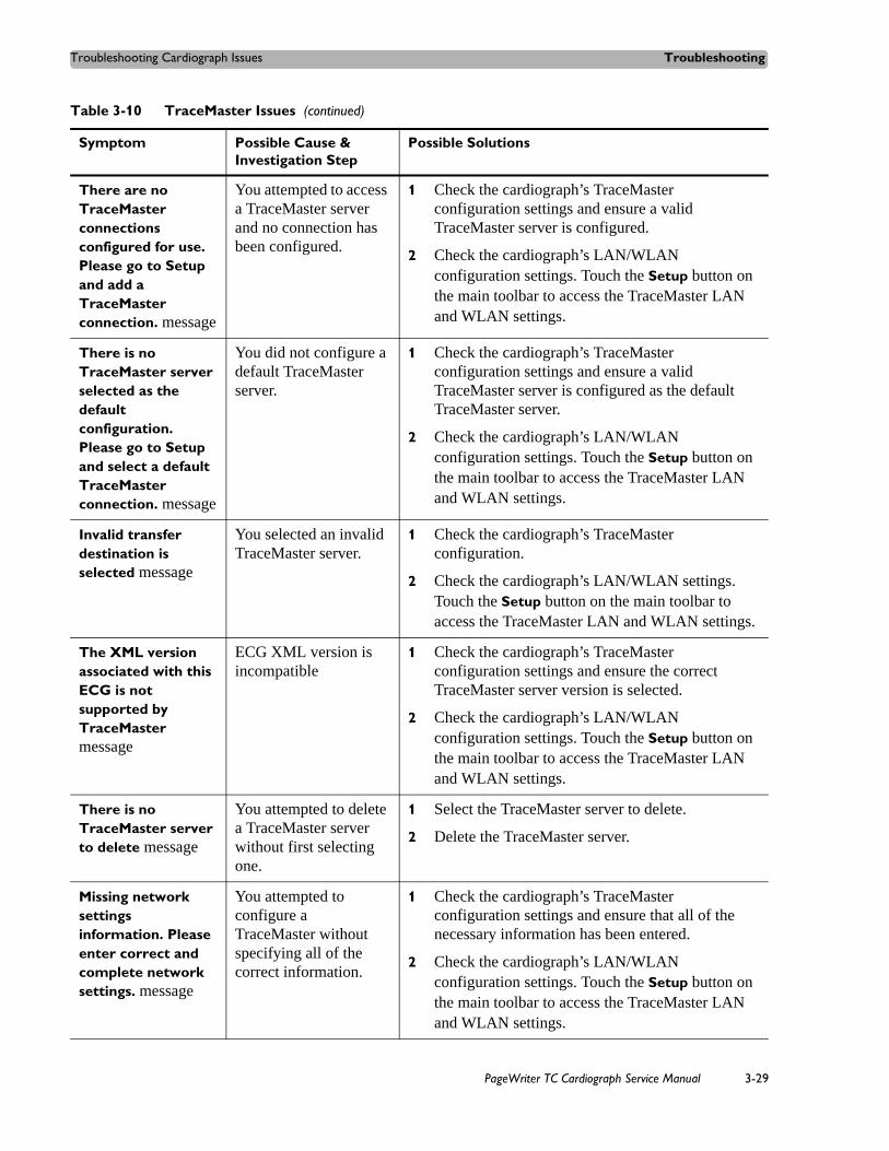
Troubleshooting Cardiograph Issues Troubleshooting
There are no TraceMaster connections configured for use. Please go to Setup and add a TraceMaster connection. message
You attempted to access a TraceMaster server and no connection has been configured.
1 Check the cardiograph’s TraceMaster configuration settings and ensure a valid TraceMaster server is configured.
2 Check the cardiograph’s LAN/WLAN configuration settings. Touch the Setup button on the main toolbar to access the TraceMaster LAN and WLAN settings.
There is no TraceMaster server selected as the default configuration. Please go to Setup and select a default TraceMaster connection. message
You did not configure a default TraceMaster server.
1 Check the cardiograph’s TraceMaster configuration settings and ensure a valid TraceMaster server is configured as the default TraceMaster server.
2 Check the cardiograph’s LAN/WLAN configuration settings. Touch the Setup button on the main toolbar to access the TraceMaster LAN and WLAN settings.
Invalid transfer destination is selected message
You selected an invalid TraceMaster server.
1 Check the cardiograph’s TraceMaster configuration.
2 Check the cardiograph’s LAN/WLAN settings. Touch the Setup button on the main toolbar to access the TraceMaster LAN and WLAN settings.
The XML version associated with this ECG is not supported by TraceMaster message
ECG XML version is incompatible
1 Check the cardiograph’s TraceMaster configuration settings and ensure the correct TraceMaster server version is selected.
2 Check the cardiograph’s LAN/WLAN configuration settings. Touch the Setup button on the main toolbar to access the TraceMaster LAN and WLAN settings.
There is no TraceMaster server to delete message
You attempted to delete a TraceMaster server without first selecting one.
1 Select the TraceMaster server to delete.
2 Delete the TraceMaster server.
Missing network settings information. Please enter correct and complete network settings. message
You attempted to configure a TraceMaster without specifying all of the correct information.
1 Check the cardiograph’s TraceMaster configuration settings and ensure that all of the necessary information has been entered.
2 Check the cardiograph’s LAN/WLAN configuration settings. Touch the Setup button on the main toolbar to access the TraceMaster LAN and WLAN settings.
Table 3-10 TraceMaster Issues (continued)
Symptom Possible Cause & Investigation Step
Possible Solutions
PageWriter TC Cardiograph Service Manual 3-29

Troubleshooting Troubleshooting Cardiograph Issues
Orders Issues
Table 3-11 Orders Issues
Symptom Possible Cause & Investigation Step
Possible Solutions
Command cannot be completed message
The TraceMaster system is busy.
Retry TraceMaster operation.
Transfer operations use network and server resource, which may occasionally be unable to service the requests.
Command canceled message
You canceled the action or specified invalid information.
Check the information specified and try again.
Internal error message
The orders list does not refresh.
Retry the operation.
There is not enough internal storage available to save new orders message
Application limitation Delete unwanted orders.
There is not enough internal storage available to download new orders message
Application limitation Delete unwanted orders.
Not all orders can be downloaded because the Worklist is full message
Application limitation Delete unwanted orders.
Orders cannot be downloaded because they have been previously archived with ECGs. Please check ECGs saved to the Main Archive. message
Order specified for download is already associated with an ECG that is currently saved to the Main Archive.
Transmit completed ECGs to TraceMaster.
3-30 PageWriter TC Cardiograph Service Manual

Troubleshooting Cardiograph Issues Troubleshooting
Invalid default TraceMaster connection for selected OrderVue inbox. Please select the correct TraceMaster connection for the inbox. message
Incorrect TraceMaster specified in the configuration.
1 Check the cardiograph’s TraceMaster configuration settings.
2 Check the cardiograph’s LAN/WLAN configuration settings. Touch the Setup button on the main toolbar to access the TraceMaster LAN and WLAN settings.
Order Error: Requested function failed message
Order application error 1 Restart the cardiograph. See “Restarting the Cardiograph” on page 3-37.
2 Repeat the order procedure that generated the error message. If the error persists, record the date and time of the error, and export the log files. See “Viewing and Saving Log Files” on page 3-50.
3 Contact the nearest Philips Response Center for further assistance, see “Contacting a Philips Response Center” on page 5-13.
Order Error: XML error message
XML order error 1 Restart the cardiograph. See “Restarting the Cardiograph” on page 3-37.
2 If the error persists, export the log files. See “Viewing and Saving Log Files” on page 3-50.
3 Contact the nearest Philips Response Center for further assistance, see “Contacting a Philips Response Center” on page 5-13.
Orders number reached the limit of 200. Not all of the new orders were appended. message
Application limitation 1 Delete unwanted orders.
2 Refine your search criteria.
The connection to the server was reset message
The network connection was broken during an orders operation.
1 Retry the operation.
2 Contact your IT department to report the network is down.
No order source selected message
You attempted to get an order without specifying a source.
Specify the source and retry the operation.
Table 3-11 Orders Issues (continued)
Symptom Possible Cause & Investigation Step
Possible Solutions
PageWriter TC Cardiograph Service Manual 3-31

Troubleshooting Troubleshooting Cardiograph Issues
Remote Query Issues
Please select at least one order message
You touched the ECG button without selecting an order.
1 Select an order.
2 Touch the ECG button.
Are you sure you want to delete the selected order(s)? message
You attempted to delete an order.
Check to make sure that you want to delete the selected order. If so, confirm the operation. If not, cancel the operation.
Selection exceeds maximum number of outboxes. Select no more than 24 outboxes. message
Application limitation Select fewer outboxes and retry the operation.
The Order Search Range cannot be left empty. Please enter a number between 0 and 99. message
You attempted to search for an order without specifying the search range.
Specify a search range and retry the operation.
Table 3-11 Orders Issues (continued)
Symptom Possible Cause & Investigation Step
Possible Solutions
Table 3-12 Remote Query Issues
Symptom Possible Cause & Investigation Step
Possible Solutions
Remote Query could not be completed message
XML application was not successfully created due to a lack of system resources.
1 Retry the operation.
2 Restart the cardiograph. See “Restarting the Cardiograph” on page 3-37.
Remote Query get list error message
TraceMaster returned the wrong ECG list.
1 Check the cardiograph’s TraceMaster configuration settings.
2 Check the cardiograph’s LAN/WLAN configuration settings.
3 Retry the operation.
3-32 PageWriter TC Cardiograph Service Manual

Troubleshooting Cardiograph Issues Troubleshooting
Remote Query get ECG error message
TraceMaster returned the wrong ECG file.
1 Check the cardiograph’s TraceMaster configuration settings.
2 Check the cardiograph’s LAN/WLAN configuration settings.
3 Check to see if the TraceMaster server is up and running.
Remote transfer error appears message
Unknown transfer error including no reply and unexpected reply.
1 Check the cardiograph’s TraceMaster configuration settings.
2 Check the cardiograph’s LAN/WLAN configuration settings.
3 Retry the operation.
No reply received from server message
The LAN connection may have been disconnected during the transfer operation.
Server may be down.
1 Check the LAN connection.
2 Check to see if the TraceMaster server is up and running.
Unexpected reply received from server message
Server may be down. 1 Check the LAN connection.
2 Check to see if the TraceMaster server is up and running.
Remote transfer schema error message
The XML schema is not supported for the selected TraceMaster server.
Check the TraceMaster Server Version in the cardiograph’s TraceMaster configuration settings.
No matching ECG is found on the selected server message
The Patient ID may be incorrect.
The ECG you are looking for does not exist on the selected server.
1 Check the Patient ID.
2 Check to see if there is an ECG with the same Patient ID.
Table 3-12 Remote Query Issues (continued)
Symptom Possible Cause & Investigation Step
Possible Solutions
PageWriter TC Cardiograph Service Manual 3-33

Troubleshooting Troubleshooting Cardiograph Issues
Fax Issues
Log File and Custom Settings Issues
Table 3-13 Fax Issues
Symptom Possible Cause & Investigation Step
Possible Solutions
Fax transmission did not complete message
Fax not completed Retry the fax operation
There is no fax recipient available to edit message
You attempted to edit a fax recipient without first selecting one.
1 Select a fax recipient.
2 Edit the fax recipient.
Missing fax recipient information. Please enter correct fax recipient settings. message
You attempted to enter a fax recipient without all of the required information.
Enter all of the required information in the Fax configuration screens.
Table 3-14 Log File Issues
Symptom Possible Cause & Investigation Step
Possible Solutions
Error accessing file message
You can't copy files from a USB memory stick when attempting to load a configuration or log file.
1 Retry the operation
2 Make sure the file exists on the USB memory stick.
Error damaged file message
You can't open a file due to a corrupted file.
Retry the operation
File already exists message
You attempted to save a log file to an existing file.
Rename the log file and retry the operation.
Input error message Invalid path and file name were specified.
Check the path and file name and ensure they are correct.
No filename specified message
You did not specify a file name in the Browse dialog box.
Specify a file name in the Browse dialog box.
Invalid filename specified message
You did not specify a file name in the Save Logs dialog box.
Specify a file name in the Save Logs dialog box.
3-34 PageWriter TC Cardiograph Service Manual

Troubleshooting Cardiograph Issues Troubleshooting
Lead Map Troubleshooting
Wireless TroubleshootingAll wireless LAN troubleshooting topics are included in this section. For further assistance with configuring the cardiograph for wireless transmission to a TraceMaster ECG Management System, or other third party ECG management system, see the PageWriter TC
USB memory stick is not detected. Please ensure that the USB memory stick is fully inserted into the USB connector (right side of cardiograph). message
Custom settings or log files cannot be saved because there is no USB memory stick in the cardiograph’s USB connector.
Insert a USB memory stick into the cardiograph’s USB connector (right side of cardiograph as the device is facing you).
The cardiograph must restart in order to load a new custom settings file message
A configuration file has been loaded.
Restart the cardiograph to use the new configuration settings.
Table 3-14 Log File Issues
Symptom Possible Cause & Investigation Step
Possible Solutions
Table 3-15 Lead Map Troubleshooting
Symptom Possible Cause & Investigation Step
Possible Solutions
Incorrect lead standard appears on the Lead Map (AAMI or IEC)
The main board was recently replaced, and the procedure reset the cardiograph lead standard (AAMI or IEC) to an incorrect setting.
1 If the main control board was recently replaced, perform a full installation of the cardiograph software using the Biomed Software Installation option in the software installation wizard. See “Installing the Software Upgrade” on page 6-3.
2 If the problem persists after a full software installation procedure, contact the Philips Response Center for further assistance. See “Contacting a Philips Response Center” on page 5-13.
PageWriter TC Cardiograph Service Manual 3-35

Troubleshooting Troubleshooting Cardiograph Issues
Cardiograph Network Configuration Guide available for download from the Philips InCenter web site (incenter.medical.philips.com).
Table 3-16 Wireless LAN Troubleshooting
Symptom Possible Cause & Investigation Step
Possible Solutions
LAN/WLAN connection is not available message
The network connection has been broken.
Contact your IT department.
Invalid IP Address message
Incorrect IP address specified for the server connection.
1 Check the cardiograph’s server configuration settings. Touch the Setup button on the main toolbar to access the server settings.
2 Contact your server administrator for information.
Invalid Subnet Mask message
Incorrect subnet mask specified in the cardiograph’s server configuration.
1 Check the cardiograph’s server configuration settings. Touch the Setup button on the main toolbar to access the server settings.
2 Contact your server administrator for information.
Invalid Default Gateway message
Incorrect default gateway specified in the cardiograph’s server configuration.
1 Check the cardiograph’s server configuration settings. Touch the Setup button on the main toolbar to access the server settings.
2 Contact your server administrator for information.
Invalid Primary WINS message
Incorrect Primary WINS specified in the cardiograph’s server configuration.
1 Check the cardiograph’s server configuration settings. Touch the Setup button on the main toolbar to access the server settings.
2 Contact your server administrator for information.
Invalid Primary DNS message
Incorrect Primary DNS specified in the cardiograph’s server configuration.
1 Check the cardiograph’s server configuration settings. Touch the Setup button on the main toolbar to access the server settings.
2 Contact your server administrator for information.
Invalid directory message
Incorrect directory specified in the cardiograph’s server configuration.
1 Check the cardiograph’s server configuration settings. Touch the Setup button on the main toolbar to access the server settings.
2 Contact your server administrator for information.
General wireless connectivity issues; unpredictable connectivity
The wireless infrastructure is not a Cisco system, and the CCX Features setting in the Summit Client Utility (SCU) is set to Optimized
1 Open the Summit Client Utility (SCU) and change the CCX Features setting to OFF if the wireless infrastructure is not a Cisco system. For information, see “Configuring Wireless Adapter Settings” on page 2-19.
2 Contact your system administrator for more information.
3-36 PageWriter TC Cardiograph Service Manual

Restarting the Cardiograph Troubleshooting
Restarting the Cardiograph To restart the cardiograph:
1 Press and hold the On/Standby button ( ) for 2-3 seconds to shut down the cardiograph.
2 Press the On/Standby button again to power on the cardiograph.
3 If steps 1 and 2 do not work, press the restart button (rear of cardiograph), see Figure 3-9 and Figure 3-10.
After approximately 20 seconds, the PageWriter TC cardiograph software identification screen appears, followed by an audible beep.
Figure 3-9 Pressing the Restart button on the PageWriter TC50 or PageWriter TC30 Cardiograph (apply gentle pressure only)
PageWriter TC Cardiograph Service Manual 3-37

Troubleshooting Using the Service Utilities
Figure 3-10 Pressing the Restart button on the PageWriter TC70 Cardiograph (apply gentle pressure only)
4 If steps 1,2, and 3 do not work, remove the batteries and the AC power from the cardiograph.
5 Reapply power and repeat steps 1 through 3.
6 If steps 1,2, and 3 do not work, remove the batteries and the AC power from the cardiograph.
7 Reapply power and repeat steps 1 through 3.
Using the Service UtilitiesThe Service Utilities enable you to:
Obtain information about the cardiograph, such as software versions, installed options, networking information, and battery status
Verify and optimize cardiograph performance using the diagnostic tests and utilities
To open the Service Utilities:
1 From the Main screen, touch the Setup button.
The Setup and Services main screen appears.
NOTE Access to the Setup screens may require entering a password.
3-38 PageWriter TC Cardiograph Service Manual

Using the Service Utilities Troubleshooting
Figure 3-11 Setup and Services Main screen
2 Touch the button next to Service Utilities.
The Setup and Service Utilities screen appears.
Using the About the Cardiograph ScreenThe About the Cardiograph screen in the Service Utility provides important information about the cardiograph that can help in the troubleshooting process. This screen provides information on:
software revision levels: including application, kernel, and PIM software
PIM option installed: 12-lead or 16-lead
networking information such as MAC and IP address
storage information, such as total RAM, percentage of RAM used, Compact Flash and USB memory stick usage
battery status, such as capacity, voltage, temperature, percent charged, and cycle count
voltage monitor information, such as AC/DC input, backlight, and PIM power
installed options
total pages printed
To access the About the Cardiograph screen:
From the Setup and Service Utilities screen, touch the About the Cardiograph tab.
PageWriter TC Cardiograph Service Manual 3-39
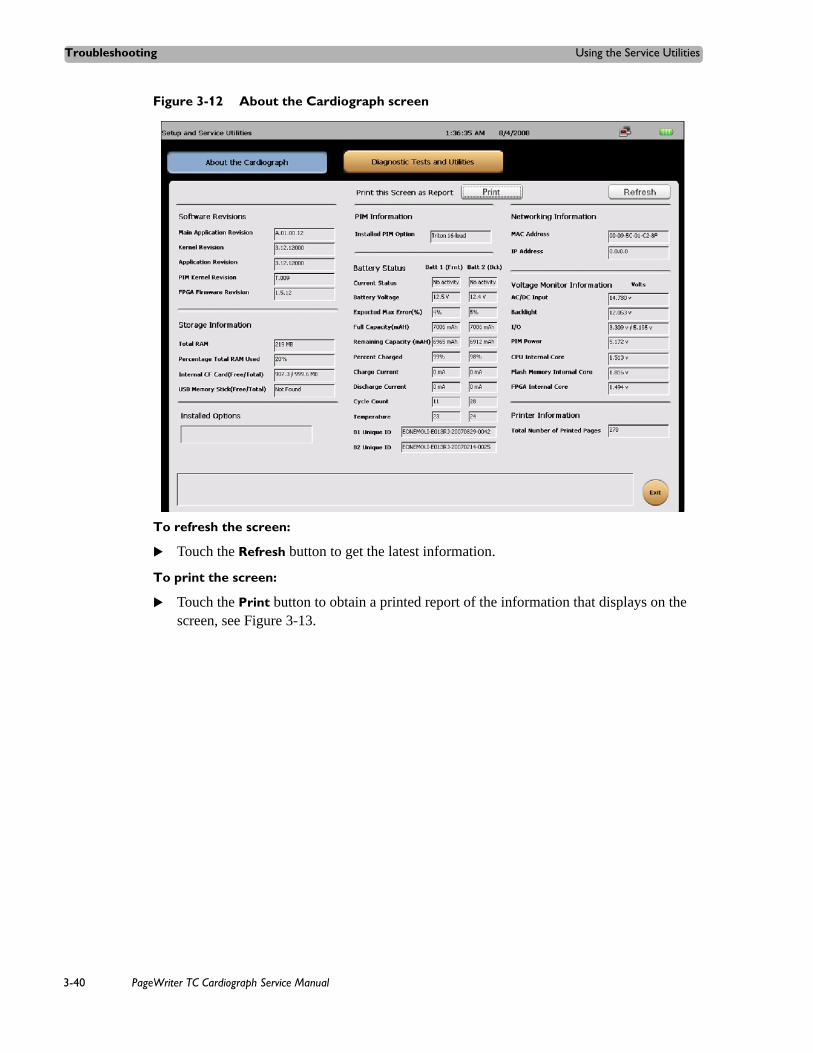
Troubleshooting Using the Service Utilities
Figure 3-12 About the Cardiograph screen
To refresh the screen:
Touch the Refresh button to get the latest information.
To print the screen:
Touch the Print button to obtain a printed report of the information that displays on the screen, see Figure 3-13.
3-40 PageWriter TC Cardiograph Service Manual

Using the Service Utilities Troubleshooting
Figure 3-13 Service Diagnostics Printed Report
PageWriter TC Cardiograph Service Manual 3-41

Troubleshooting Using the Service Utilities
Using the Diagnostic Tests and UtilitiesThe Diagnostic Tests and Utilities help you to troubleshoot issues with the cardiograph. There are two level of tests.
Maintenance Tests – used to verify or to optimize cardiograph performance. These tests can be used as the first step in identifying a technical problem with the cardiograph.
Diagnostic Tests – used to identify and to troubleshoot a technical problem with the cardiograph and require a password to access.
All test results are entered in the Event log that is displayed on the screen. Additionally, you can save all log files to a USB memory stick. (See “Viewing and Saving Log Files” on page 3-50 for information on log files.)
To access the Diagnostic Tests and Utilities screen:
From the Setup and Service Utilities screen, touch the Diagnostic and Test Utilities tab.
Figure 3-14 Diagnostic and Tests Utilities screen
3-42 PageWriter TC Cardiograph Service Manual

Using the Service Utilities Troubleshooting
The Maintenance section of the screen lists the four maintenance tests.
Printer Test
The Printer Test is used to verify that the cardiograph printer is able to correctly print the test page. Use this test to verify proper printer performance or when reports appear to have print quality errors.
To perform the Printer Test:
1 Touch the Printer Test button.
The message Printing Test Page... appears and the test page prints out.
2 Review the printer test page at points A, B, C, and D as shown on Figure 3-15.
Test Page
Printer Test 3-43
Touch Screen Calibration and Test 3-45
Patient Interface Module (PIM) Test 3-45
Lead Wire Shortage Test 2-15
Ping Test 3-45
Test Point
Description
A The stepped bars are sharp edged and printed cleanly without distortion or missing segments
B The spacing between the vertical lines is 25 mm with a discrepancy of no more or less than 2%
C The diagonal lines should be straight and printed cleanly without distortion or breaks in the lines
D The character set is printed cleanly without distortion or missing characters, and all characters are clearly legible
PageWriter TC Cardiograph Service Manual 3-43

Troubleshooting Using the Service Utilities
Figure 3-15 Printer Test Page
DC
B
A
3-44 PageWriter TC Cardiograph Service Manual

Using the Service Utilities Troubleshooting
If the printer test page matches the printer test points as described in the previous table and the message Printer Test Passed appears, the cardiograph has passed the printer test.
If the printer test page does not match the printer test points as described in the previous table but the message Printer Test Passed appears, it is possible the print head is damaged. If the printer test page does not match the printer test points and the message Printer Test Failed appears, the cardiograph has failed the print test. Proceed with troubleshooting and possibly replacing the print head assembly. Contact the Philips Response Center for further assistance, see “Contacting a Philips Response Center” on page 5-13.
Touch Screen Calibration and Test
For information on Touch Screen Calibration and Test, see “Maintaining the Touch Screen” on page 2-16.
Patient Interface Module (PIM) Test
For information on the Patient Interface Module (PIM) Test, see “Patient Interface Module (PIM) Test” on page 2-14.
Lead Wire Shortage Test
For information on the lead wire shortage test, see “Lead Wire Performance Test” on page 2-15.
Ping Test
For information on the Ping Test, see “Ping Test” on page 2-15.
Using the Diagnostic TestsMore comprehensive diagnostic tests and operating statistics are provided in the Diagnostic Tests section of the Service Utility. These tests are used to identify and to troubleshoot a technical problem with the cardiograph and require a password to access. All test results are entered in the Event log that is displayed on the screen. Additionally, you can save all log files to a USB memory stick. See “Viewing and Saving Log Files” on page 3-50 for information on log files.
The following tests are available on the Diagnostic Tests menu.
Table 3-17 Diagnostic Tests
Test Page
Flash Memory Test 3-46
Internal Compact Flash Test 3-47
Audio Test 3-47
Keyboard/Hardware Key Test 3-47
PageWriter TC Cardiograph Service Manual 3-45

Troubleshooting Using the Service Utilities
To access the Diagnostic Test screen:
1 From the Main screen, touch the Setup button. The Setup and Services main menu appears.
2 Touch Service Utilities.The Service Utilities screen appears.
3 Touch the Diagnostic and Test Utilities button (top of screen).
4 Use the Tab key on the keyboard to move the cursor to the Enter Password field.
5 Use the keyboard to enter the password (000000) for Diagnostic Tests and touch the Submit button.
TIP If entering the password using an AZERTY (French) keyboard, press and hold the Enter key (on keyboard) while entering the password code (000000).
The Diagnostic Test screen appears.
Figure 3-16 Diagnostic Test screen
Flash Memory Test
This test verifies that the onboard Flash memory is working properly.
To test the onboard Flash memory:
1 Touch the Flash Memory Test button.
A message lets you know if the onboard Flash memory passed the test.
3-46 PageWriter TC Cardiograph Service Manual

Using the Service Utilities Troubleshooting
2 Select Close.
If the onboard flash card fails the test, try the test again.
Internal Compact Flash Test
This test verifies that the internal Compact Flash is working properly.
To test the Internal Compact Flash:
1 Touch the Internal Compact Flash button.
A message lets you know if the Internal Compact Flash passed the test.
2 Touch the Close button.
If the compact flash card fails the test, try the test again.
Audio Test
This test determines whether the cardiograph is emitting sounds.
To test audio:
1 Touch the Audio button from the list.
The test emits audible chime tones.
2 Select Yes when the see the message Did you hear the sound playing?
A message lets you know that the audio test passed.
3 Select No if you did not hear the sound playing.
A message lets you know that the audio test fails.
4 Touch the Close button.
Keyboard/Hardware Key Test
A successful Keyboard test is one in which each key is properly recognized when pressed.
To test the keyboard:
1 Touch the Keyboard/Hardware Key Test button.
The Keyboard Test window appears.
PageWriter TC Cardiograph Service Manual 3-47
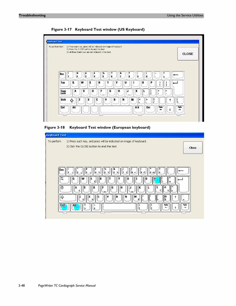
Troubleshooting Using the Service Utilities
Figure 3-17 Keyboard Test window (US Keyboard)
Figure 3-18 Keyboard Test window (European keyboard)
3-48 PageWriter TC Cardiograph Service Manual

Using the Service Utilities Troubleshooting
Figure 3-19 Keyboard Test window (French AZERTY keyboard)
Figure 3-20 Keyboard Test window (Russian keyboard)
2 Press each key on the keyboard. If a key is highlighted, the key is registered.
3 After all the keys are highlighted, touch the Close button to finish the test.
A message lets you know if the test passed or failed. The test fails if any of the keys are not recognized when you press them or if you do not press all of the keys.
PageWriter TC Cardiograph Service Manual 3-49

Troubleshooting Viewing and Saving Log Files
Viewing and Saving Log FilesAll test results are entered in the Event Log that is displayed on the screen. Additionally, you can save all log files to a USB memory stick using the Save Logs feature in Setup, or use the key command Ctrl + Alt + O from any screen. Ensure that a USB memory stick is firmly connected to the cardiograph before saving log files. Also, the cardiograph can be configured to automatically or manually transmit log files directly to a specified TraceMaster ECG Management System server, or to any other networked computer or server that is accessible over a LAN or WLAN. For more information on configuring and using a remote server to receive log files, see the PageWriter TC Cardiograph Network Configuration Guide.
About Log Files Log files continuously record operating information about the cardiograph including events, errors, application integrity, battery power levels, memory use, test results, and user events related to ECG processing, along with the time and date of each event.
Figure 3-21 shows the Event Log as it appears on the Diagnostic Tests and Utilities screen.
Figure 3-21 Event Log Screen
3-50 PageWriter TC Cardiograph Service Manual
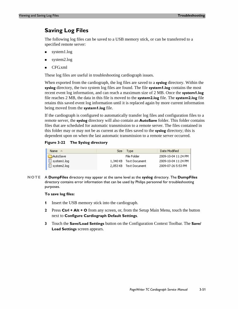
Viewing and Saving Log Files Troubleshooting
Saving Log FilesThe following log files can be saved to a USB memory stick, or can be transferred to a specified remote server:
system1.log
system2.log
CFG.xml
These log files are useful in troubleshooting cardiograph issues.
When exported from the cardiograph, the log files are saved to a syslog directory. Within the syslog directory, the two system log files are found. The file system1.log contains the most recent event log information, and can reach a maximum size of 2 MB. Once the system1.log file reaches 2 MB, the data in this file is moved to the system2.log file. The system2.log file retains this saved event log information until it is replaced again by more current information being moved from the system1.log file.
If the cardiograph is configured to automatically transfer log files and configuration files to a remote server, the syslog directory will also contain an AutoSave folder. This folder contains files that are scheduled for automatic transmission to a remote server. The files contained in this folder may or may not be as current as the files saved to the syslog directory; this is dependent upon on when the last automatic transmission to a remote server occurred.
Figure 3-22 The Syslog directory
NOTE A DumpFiles directory may appear at the same level as the syslog directory. The DumpFiles directory contains error information that can be used by Philips personnel for troubleshooting purposes.
To save log files:
1 Insert the USB memory stick into the cardiograph.
2 Press Ctrl + Alt + O from any screen, or, from the Setup Main Menu, touch the button next to Configure Cardiograph Default Settings.
3 Touch the Save/Load Settings button on the Configuration Context Toolbar. The Save/Load Settings screen appears.
PageWriter TC Cardiograph Service Manual 3-51

Troubleshooting Viewing and Saving Log Files
Figure 3-23 Save/Load Settings screen
4 Under Save Logs, make sure that USB memory stick is highlighted.
5 Touch the Save button. The Save Logs window appears.
Figure 3-24 Save Logs screen
6 To save the log files to the default file name and location, touch the Save button. Proceed to step 10.
The USB memory stick flashes while the log file is being saved. This can take up to 20 seconds.
7 To change the file name or location, touch the Browse button.
The Select file directory screen appears.
3-52 PageWriter TC Cardiograph Service Manual

Viewing and Saving Log Files Troubleshooting
Figure 3-25 Select File Directory screen
8 Touch the New Folder button to create a folder for the log files and to specify a different file name, if desired. Touch the OK button.
9 Touch the Save button to save the log files to the specified file name and location.
The USB memory stick flashes while the log file is being saved. This can take up to 20 seconds.
10 Remove the USB memory stick when the file save is complete.
PageWriter TC Cardiograph Service Manual 3-53

Troubleshooting Viewing and Saving Log Files
3-54 PageWriter TC Cardiograph Service Manual

4
3Performance Verification andSafety Tests
This chapter describes the tests and inspections required to verify performance of the PageWriter TC cardiograph following a service event.
This chapter provides the following information:Required Testing Levels . . . . . . . . . . . . . . . . . . . . . . . . . . . . . . . . . . . . . . . . . . . . . . . . . . . . 4-1External Repairs . . . . . . . . . . . . . . . . . . . . . . . . . . . . . . . . . . . . . . . . . . . . . . . . . . . . . . . . . . 4-1Internal Repairs . . . . . . . . . . . . . . . . . . . . . . . . . . . . . . . . . . . . . . . . . . . . . . . . . . . . . . . . . . . 4-2Upgrades . . . . . . . . . . . . . . . . . . . . . . . . . . . . . . . . . . . . . . . . . . . . . . . . . . . . . . . . . . . . . . . . 4-2Test and Inspection Matrix . . . . . . . . . . . . . . . . . . . . . . . . . . . . . . . . . . . . . . . . . . . . . . . . . . 4-4Test Equipment . . . . . . . . . . . . . . . . . . . . . . . . . . . . . . . . . . . . . . . . . . . . . . . . . . . . . . . . . . . 4-5Performance Verification Tests . . . . . . . . . . . . . . . . . . . . . . . . . . . . . . . . . . . . . . . . . . . . . . . 4-5
Visual Inspection (V) . . . . . . . . . . . . . . . . . . . . . . . . . . . . . . . . . . . . . . . . . . . . . . . . . . . 4-5Power On Test (PO) . . . . . . . . . . . . . . . . . . . . . . . . . . . . . . . . . . . . . . . . . . . . . . . . . . . . 4-6Individual Functional Tests . . . . . . . . . . . . . . . . . . . . . . . . . . . . . . . . . . . . . . . . . . . . . . 4-6Safety Tests. . . . . . . . . . . . . . . . . . . . . . . . . . . . . . . . . . . . . . . . . . . . . . . . . . . . . . . . . . 4-12
Required Testing LevelsThe Performance Verification Tests verify proper operation of the PageWriter TC cardiograph following a service event. The level of testing required corresponds to the type of service performed.
NOTE Installation and Preventive Maintenance are not considered service events since the cardiograph is designed to be installed and maintained by the user. Service Events are divided into two categories: Repairs and Upgrades. Repairs are then further divided into External Repairs and Internal Repairs.
External RepairsExternal Repairs consist of repairs or replacements of one or more items. Repair or replacement of these items does not require you to open the cardiograph case, therefore only a limited number of tests are necessary to verify performance post-repair. External repairs that involve the PIM, PIM data cable, and PIM lead set require an ECG simulation test to verify proper ECG signal path.
The typical external repairs include:
PIM
4-1

Performance Verification and Safety Tests Internal Repairs
Patient Leads
PIM data cable
Labels
Batteries
Paper Tray
AC Power Cord
AC Power Supply
Wireless LAN card
USB external devices
Barcode reader
Trolley
External cables
Refer to Table 4-18 for the required test blocks that must be performed after any external repair occurs.
Internal RepairsIf the case was opened, regardless of the repair, you must perform additional Performance Verification Tests. Refer to Table 4-18 for the required test blocks that must be performed after any internal repair.
UpgradesNOTE There are no upgrades available for the PageWriter TC70 cardiograph.
Most PageWriter TC50 cardiograph and PageWriter TC30 cardiograph upgrades are installed by the user, and are not considered service events. The only exceptions are upgrades for the software and the magnetic card reader. Refer to Table 4-18 for the required test blocks that must performed after these upgrades.
Table 4-1 Tests Required
Service Event Test Blocks Required
Repairs External Repairs not involving the patient module (battery, AC power supply, labels, or cart)
1 Visual Inspection
2 Power On test
3 Functional tests specific to components repaired
4-2 PageWriter TC Cardiograph Service Manual
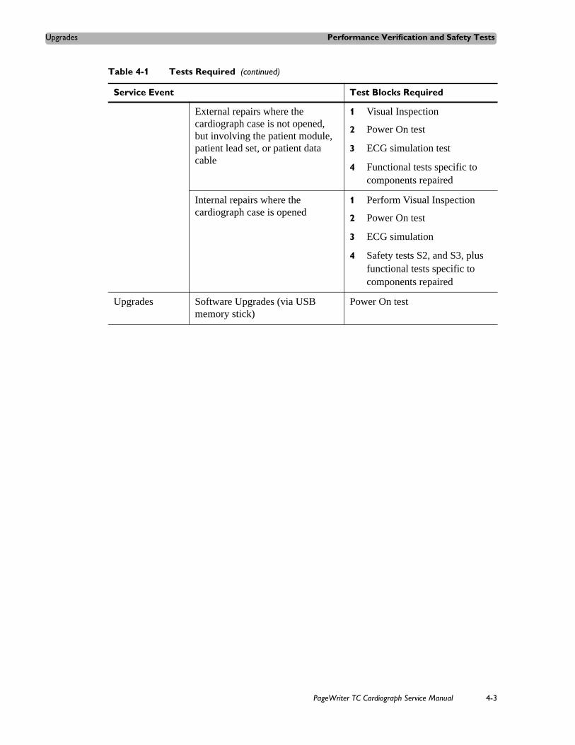
Upgrades Performance Verification and Safety Tests
External repairs where the cardiograph case is not opened, but involving the patient module, patient lead set, or patient data cable
1 Visual Inspection
2 Power On test
3 ECG simulation test
4 Functional tests specific to components repaired
Internal repairs where the cardiograph case is opened
1 Perform Visual Inspection
2 Power On test
3 ECG simulation
4 Safety tests S2, and S3, plus functional tests specific to components repaired
Upgrades Software Upgrades (via USB memory stick)
Power On test
Table 4-1 Tests Required (continued)
Service Event Test Blocks Required
PageWriter TC Cardiograph Service Manual 4-3

Performance Verification and Safety Tests Test and Inspection Matrix
Test and Inspection MatrixThe following Test and Inspection Matrix describes the various test blocks, expected test results, and what you need to document on the service record.
Table 4-2 Test and Inspection Matrix
Test Block Name
Test or Inspection to Perform Expected (Passing) Test Results
What to Record on a Service Record
Visual Inspection (V)
Perform visual inspection (page 4-5). If there is no apparent wear, damage, or corrosion the visual inspection passes.
V:P (pass)
V:F (fail)
Power On (PO) Power on the unit (page 4-6).
Watch display for errors.
See the Troubleshooting chapter for a list of errors.
If the display shows the Software Identification screen followed by the Main screen, the Power On test passes.
PO:P (pass)
PO:F (fail)
Individual Functional Tests. The Printer, Touch Screen, PIM and Keyboard tests can be run from within the Service Utilities.
Printer Test (P) Perform Printer Test (page 4-9). As described in the test procedure.
P:P (pass)
P:F (fail)
Touch Screen Test (TD)
Perform the Touch Screen Display and Calibration tests (page 4-9).
As described in the test procedure.
TD:P (pass)
TD:F (fail)
PIM Test (PIM) Perform the PIM test (page 4-10).
As described in the test procedure.
PIM:P (pass)
PIM:F (fail)
Keyboard Test (K)
Perform the Keyboard test (page 4-10).
As described in the test procedure.
K:P (pass)
K:F (fail
Leadwire Test (LW)
Test the lead wires for both open and shorts (page 4-10).
As described in the test procedure.
LW:P (pass)
LW:F (fail)
ECG Simulation (ECG)
Connect a 12 Lead Patient Simulator to the lead set and print a 12 lead ECG. Visually analyze the printout (page 4-11).
If there is trace activity in all leads with no notable distortion or noise, and cal pulses of proper duration and amplitude, then the ECG Simulation passes.
ECG:P (pass)
ECG:F (fail)
4-4 PageWriter TC Cardiograph Service Manual

Test Equipment Performance Verification and Safety Tests
Test EquipmentThe following test equipment is required to perform the complete set of Performance Verification tests:
ECG Simulator
Electrical Safety Tester
USB memory stick with the most recent PageWriter TC50 software
Performance Verification Tests
Visual Inspection (V)Before beginning the inspection, press the On/Standby button ( ) for 2 to 3 seconds to put the cardiograph in Standby mode and unplug the power cord from the wall outlet. Inspect the cardiograph external surfaces for the following:
Worn or damaged power cord
Loose or missing hardware
Mechanical damage
Evidence of liquid spill
Worn printer drive gear
Worn printer roller
Corroded or damaged reusable electrodes, if present
Safety (S1) PageWriter TC50/TC30 cardiographs only
Earth Resistance Test (page 4-13). Test limits: 200 mOhm using a reduced 200 mA test current
Example:S1:P/100 mOhm
Safety (S2) Equipment leakage current
(page 4-13).
SF Maximum leakage current< 1000 uA
Example: S2:P/999
Safety (S3) Leads leakage current (page 4-14).
Source (Normal condition)
With Mains on applied part (Single Fault Condition)
< 10 uA x1
< 50 uA x3
Example: S3:P/5/20
Table 4-2 Test and Inspection Matrix (continued)
Test Block Name
Test or Inspection to Perform Expected (Passing) Test Results
What to Record on a Service Record
PageWriter TC Cardiograph Service Manual 4-5

Performance Verification and Safety Tests Performance Verification Tests
Damaged patient leads
Dirt/paper residue on the thermal print head
Frayed or damaged wiring
Visible touch screen damage
Replace any damaged or missing items.
Clean the patient data cable and patient leads as necessary. For more information, see “Cardiograph and PIM Cleaning” on page 2-3, and see “Patient Data Cable and Lead Wire Cleaning” on page 2-4.
Power On Test (PO)Restart the cardiograph to process a completed Power On test.
To restart the cardiograph:
1 Press the On/Standby button ( ) for 2-3 seconds to shut down the cardiograph.
2 Press the On/Standby button again to power on the cardiograph.
After approximately 20 seconds, the PageWriter TC cardiograph software identification screen appears, followed by an audible beep.
The following self-tests are automatically performed during reboot:
Software CRC Test
Flash Memory: onboard CompactFlash (CF) and internal CompactFlash (CF)
PIM Status
USB Detect
Individual Functional TestsYou perform the Printer, Touch Screen, PIM, and Keyboard tests using the Service Utilities.
Accessing the Service Utilities
To access the Service Utilities:
1 From the Main screen, touch the Setup button.
The Configuration Setup and Services Utilities main screen appears.
4-6 PageWriter TC Cardiograph Service Manual

Performance Verification Tests Performance Verification and Safety Tests
Figure 4-26 Configuration Setup and Services Main screen
2 Touch Service Utilities.
The Setup and Service Utilities screen appears with the About the Cardiograph tab displayed.
PageWriter TC Cardiograph Service Manual 4-7

Performance Verification and Safety Tests Performance Verification Tests
Figure 4-27 Setup and Service Utilities About the Cardiograph screen
For detailed information about the components of this screen, see “Using the About the Cardiograph Screen” on page 3-39.
3 Touch the Diagnostic and Test Utilities tab.
4-8 PageWriter TC Cardiograph Service Manual

Performance Verification Tests Performance Verification and Safety Tests
Figure 4-28 Diagnostic and Tests Utilities screen
Printer Test (P)
The Printer Test is used to verify that the cardiograph printer is able to correctly print the test page. Use this test to verify proper printer performance or when reports appear to have print quality errors.
To perform the Printer test:
1 Touch the Printer Test button.
2 See “Printer Test” on page 3-43 for instructions.
Touch Screen Display and Calibration Test (TD)
The touch screen can be calibrated at any time. Calibration is recommended if it requires many attempts to select an item on the screen, or if selecting items on a specific area of the screen is difficult.
The touch screen may also require calibration if the cardiograph is used in different settings (seated instead of standing) or by users of significantly different height. The touch screen may
PageWriter TC Cardiograph Service Manual 4-9

Performance Verification and Safety Tests Performance Verification Tests
need to be recalibrated to work optimally in the new setting or with the new user. The Touch Screen Calibration procedures and tests include:
Force Calibration procedure
Touch Calibration test
To calibrate the touch screen with the Force Calibration procedure:
1 Touch Force Calibration.
2 See “Touch Screen Calibration and Test” on page 3-45 for instructions.
To calibrate the touch screen with the Touch Calibration test:
1 Touch Start Test.
2 See“Touch Screen Calibration and Test” on page 3-45 for instructions.
PIM Test (PIM)
This test is used to confirm that the Patient Interface Module (PIM) is communicating with the cardiograph. This test can be performed when the cardiograph displays PIM error messages, or when the cardiograph is unable to acquire data from the PIM. Be sure that the PIM patient data cable is securely attached to the PIM connector on the rear of the cardiograph before performing the test.
If this test fails, it may indicate a problem with the PIM or with the PIM patient data cable.
To perform the PIM Test:
1 Touch the Patient Interface Module (PIM) Test button.
2 See “Patient Interface Module (PIM) Test” on page 3-45 for instructions.
Keyboard Test (K)
A successful Keyboard test is one in which each key is properly recognized when pressed.
To perform the Keyboard Test:
1 Touch the Keyboard/Hardware Key Test button.
2 See “Keyboard/Hardware Key Test” on page 3-47 for instructions.
Leadwire Tests (LW)
Run the lead wire open and short tests. See “Using the Service Utilities” on page 3-38 and “Lead Wire Shortage Test” on page 3-45 for instructions.
4-10 PageWriter TC Cardiograph Service Manual

Performance Verification Tests Performance Verification and Safety Tests
ECG Simulation (ECG)
Taking an ECG using a 12-lead ECG simulator allows you to verify areas of operation that the extended self-test cannot check:
Integrity of the patient leads
Accuracy of the paper speed (not available on all simulators)
Accuracy of the gain settings (not available on all simulators)
The recorded ECG trace should look similar to the one shown in the following figure. Trace differences may result from differences in simulators, simulators settings, and from differences in configuration and control settings on the cardiograph.
Figure 4-29 Simulated 12-Lead ECG
To make a simulated ECG recording
1 Connect the PIM lead wires to the simulator.
Verify that all lead wires are connected by observing the display for flat lines.
2 Touch the Map button on the Toolbar.
Check the leads map to be sure that a red x does not appear next to any electrodes.
3 Firmly pull each lead wire tight, and then look for excessive noise on the display (may be indicated by yellow or orange waveforms).
4 Touch the ECG button on the toolbar. If a message appears that no patient information has been entered, touch the Continue button.
Depending on how the cardiograph is configured, the ECG may automatically print. If not, touch the Print button.
PageWriter TC Cardiograph Service Manual 4-11

Performance Verification and Safety Tests Performance Verification Tests
5 Verify the following items when printing is complete:
– Trace activity for all leads. Confirms integrity for all patient electrodes and leadwires. Noise should measure less than one (1) mm, with no baseline wander.
– No gross distortion of complexes or calibration pulses (no overshoot and so forth).
– Duration for calibration pulses for correct paper speed. With cardiograph set to record at 25 mm/sec, the calibration pulse should measure 5mm (calibration pulse duration is 200 ms).
– Calibration pulse amplitude is correct.
NOTES An arrhythmia simulator is not an acceptable tool for verifying computerized ECG analysis. The analysis software is biased to process human ECG data.
Noise may be an artifact of poor connections to the simulator or position of the cables. If noise appears, check the connectors or adjust the cable drape.
Safety Tests This section covers tests of the cardiograph’s electrical safety.
NOTE The PageWriter TC70 cardiograph is an electrical Class II device in which the protection against electrical shock does not rely on basic insulation and a protective earth conductor, but on double and reinforced insulation.
Test Notes
Use the procedures called out by the manufacturer of the safety analyzer in use.
Test both Normal and Reverse polarity line connections for each test, and record the worst-case value.
Use the barrel of the PIM connector to connect a test lead to chassis bare metal for the leakage tests.
PIM connector
4-12 PageWriter TC Cardiograph Service Manual

Performance Verification Tests Performance Verification and Safety Tests
Safety Test S1 - Earth Resistance Test
Limits: 200 mOhm using a reduced 200 mA test current
Safety Test S2 - Equipment Leakage
Applicable to Class 1 and 2, type B, BF, CF. For Class 1: Protective Earth conductor is not connected. S = open. Measure equivalent leakage current to mains part from all Applied Parts and enclosure in parallel. Measures grounded and ungrounded metal parts.
Maximum leakage current < 1000 uA.
Reference: VDE 0751.
PageWriter TC Cardiograph Service Manual 4-13

Performance Verification and Safety Tests Performance Verification Tests
Safety Test S3 - Leads Leakage Current
CF
Applicable to Class 1 and 2, type CF.
Measures equivalent leakage current to mains part and enclosure from all Applied Parts in parallel.
Maximum leakage current CF < 50/100 uA. Tested separately (50 uA) or together (100 uA).
Check each type CF Applied Part separately with all patient connections short-circuited together.
Include all accessible conductive parts of enclosure.
4-14 PageWriter TC Cardiograph Service Manual

5
1Parts and Supplies
The part numbers for all available replacement parts for the PageWriter TC cardiographs are listed in this section. If the replacement part that you need is not listed in this section, please contact the nearest Philips Response Center for further assistance. See “Contacting a Philips Response Center” on page 5-13.
This chapter provides the following information:Ordering Replacement Parts . . . . . . . . . . . . . . . . . . . . . . . . . . . . . .5-1PageWriter TC70/TC50/TC30 Cardiograph Cart Replacement Parts5-2PageWriter TC70/TC50/TC30 Customer Replacement Parts . . . . .5-3
Other PageWriter TC Cardiograph Replacement Parts . . .5-5Paper Tray Replacement Parts . . . . . . . . . . . . . . . . . . . . . . . . . . . . .5-6Patient Interface Module (PIM) Replacement . . . . . . . . . . . . . . . . .5-7Supplies and Ordering Information . . . . . . . . . . . . . . . . . . . . . . . . .5-7
Ordering Supplies . . . . . . . . . . . . . . . . . . . . . . . . . . . . . . . .5-7Special Note about Welsh Bulb Electrodes . . . . . . . . . . . .5-8PageWriter TC Cardiograph Supply Part Numbers . . . . . .5-8
Ordering Options and Upgrades . . . . . . . . . . . . . . . . . . . . . . . . . .5-11Contacting a Philips Response Center . . . . . . . . . . . . . . . . . . . . . .5-13
Ordering Replacement PartsFor further assistance, contact your local Philips Medical Systems Response Center. See “Contacting a Philips Response Center” on page 5-13.
5-1

Parts and Supplies PageWriter TC70/TC50/TC30 Cardiograph Cart Replacement Parts
PageWriter TC70/TC50/TC30 Cardiograph Cart Replacement Parts
Figure 5-1 PageWriter TC70/TC50/TC30 Cardiograph Cart Replacement Parts
5-2 PageWriter TC Cardiograph Service Manual

Parts and Supplies PageWriter TC70/TC50/TC30 Customer Replacement Parts
NOTE The parts listed in Table 5-2 that contain an asterisk (*) after the part number are only available through your sales representative or distributor.
PageWriter TC70/TC50/TC30 Customer Replacement Parts
The following section lists all of the customer replacement parts for all models of the PageWriter TC cardiograph. If the replacement part that you need is not listed in this section, please contact the nearest Philips Response Center for further assistance. See “Contacting a Philips Response Center” on page 5-13.
NOTE The parts listed in this section are applicable to all models of the PageWriter TC cardiograph.
Table 5-1 PageWriter TC70 Cardiograph Cart Replacement Parts List
Reference Number Part Number Description
1 989803159011* Cart Patient Cable Arm
2 989803149561* Additional Cart Storage Bin
3 and 4 453564054291 Directional locking caster
5 453564050721 Swivel Caster
6 453564054301 Full Locking Caster
7 989803159001* Additional Wire Basket PageWriter TC70 Cardiograph only
8 453564094411 Cart Power Supply 15V, 80WPageWriter TC70 Cardiograph only
PageWriter TC Cardiograph Service Manual 5-3

Parts and Supplies PageWriter TC70/TC50/TC30 Customer Replacement Parts
Figure 5-2 PageWriter TC70/TC50/TC30 Cardiograph Replacement Parts
Table 5-2 PageWriter TC70/TC50/TC30 Replacement Parts
Reference Number Part Number Description
1 453564094281 PageWriter TC70 Keyboard Assembly (USA English)
1 453564094291 PageWriter TC70 Keyboard Assembly (European)
1 453564094301 PageWriter TC70 Keyboard Assembly (French)
1 453564215081 PageWriter TC70 Keyboard Assembly (Russian)
1 453564171161 PageWriter TC50 Keyboard Assembly (USA English)
1 453564171171 PageWriter TC50 Keyboard Assembly (European)
1 453564171181 PageWriter TC50 Keyboard Assembly (French)
5-4 PageWriter TC Cardiograph Service Manual

Parts and Supplies PageWriter TC70/TC50/TC30 Customer Replacement Parts
Other PageWriter TC Cardiograph Replacement Parts
1 453564203431 PageWriter TC50 Cardiograph Keyboard Assembly (Russian)
1 453564201791 PageWriter TC30 Cardiograph Keyboard Assembly (USA English)
1 453564201811 PageWriter TC30 Cardiograph Keyboard Assembly (European)
1 453564203421 PageWriter TC30 Cardiograph Keyboard Assembly (French)
1 453564203431 PageWriter TC30 Cardiograph Keyboard Assembly (Russian)
2 453564171271 Battery Door
3 989803164281* Class B Patient Data Cable
Notes: For more information about Class B Patient Data Cables, see “About Class A and Class B Patient Data Cables and PIMs” on page 1-27. This part is only available through your sales representative or distributor.
4 453564171441 Rubber Rear Screw Cover
5 453564171881 PageWriter TC50/TC30 only: 1.6 amp (250 V) Replacement Fuse
Table 5-2 PageWriter TC70/TC50/TC30 Replacement Parts (continued)
Reference Number Part Number Description
Table 5-3 Other PageWriter TC Cardiograph Replacement Parts
Part Number Description
453564119001 Cardiograph to trolley mounting screws and washers (2)
453564096331 Assorted screws consisting of:
M3 x 8mm T10 (20)
M3 x 6mm T10 (2, for I/O board assembly)
M4 x 8mm T 20 (6)
Display rubber plugs (4)
PageWriter TC Cardiograph Service Manual 5-5

Parts and Supplies Paper Tray Replacement Parts
Paper Tray Replacement PartsFigure 5-3 Paper Tray Parts Exploded Diagram
Table 5-4 Paper Tray Replacement Parts List
Reference Number Description Part Number
1 Paper Tray A4 Metric Spacer for A4 paper 453564172291
2 Paper Guide for A4 paper 453564172301
Complete Paper Tray Assembly 453564171421
5-6 PageWriter TC Cardiograph Service Manual

Parts and Supplies Patient Interface Module (PIM) Replacement
Patient Interface Module (PIM) ReplacementThe same Patient Interface Module (PIM) is used on all models of the PageWriter TC cardiograph. Before ordering a replacement PIM, check the Service Number on the bottom PIM label. Record this Service Number and keep this information with you when ordering replacement PIM parts, as this number determines which replacement part is ordered. For further assistance, contact the nearest Philips Response Center. See “Contacting a Philips Response Center” on page 5-13.
Figure 5-4 Service Number on PIM Label (bottom of PIM)
Supplies and Ordering InformationThe part numbers for all supplies for the PageWriter TC cardiograph are listed in this section.
Ordering SuppliesAll supplies may be ordered on the web at:
http://shop.medical.philips.com
Use the part numbers listed in this section to ensure that the correct supplies are ordered.
Service Number
PageWriter TC Cardiograph Service Manual 5-7

Parts and Supplies Supplies and Ordering Information
Special Note about Welsh Bulb ElectrodesFigure 5-5 Welsh Bulb Electrode
Welsh Bulb electrodes are offered as an optional supply part with the PageWriter TC cardiograph. Special care is necessary when using these electrodes. Pay special attention to all warnings associated with these electrodes. For information on cleaning the reusable Welsh Bulb electrodes, see “Reusable Electrode Cleaning" on page 3-4. Philips Medical Systems recommends the use of disposable electrodes with the PageWriter TC cardiograph.
WARNING The Welsh bulb electrodes (available as an accessory for the cardiograph) do not meet the requirements of IEC 60601-2-25 for defibrillation recovery time, and cannot be reliably used for patient diagnosis immediately following defibrillation.
WARNING Always clean and disinfect reusable electrodes before patient use. See “Reusable Electrode Cleaning” on page 3-4 for information on cleaning and disinfecting reusable electrodes. Failure to properly clean and disinfect reusable electrodes before patient use may cause infectious materials to be transferred between patients.
CAUTION The Welsh bulb electrodes contain natural rubber latex which may cause allergic reactions.
PageWriter TC Cardiograph Supply Part Numbers
PIM Patient Data Cable
Part Number Description
989803164281 Patient Data Cable, Class B 8-pin (2.0 meters/6.56 feet length)
Complete Lead Sets
Part Number Description
989803151631 Complete AAMI Lead Set for Standard 12 Leads (arm lead 99 cm/39 in, leg lead 104.1 cm/41 in, chest leads 69.8 cm/27.5 in)
989803151641 Complete IEC Lead Set for Standard 12 Leads (arm lead 99 cm/39 in, leg lead 104.1 cm/41 in, chest leads 69.8 cm/27.5 in)
989803151711 Limb Lead Set (AAMI/IEC) (arm lead 99 cm/39 in, leg lead 104.1 cm/41 in)
5-8 PageWriter TC Cardiograph Service Manual

Parts and Supplies Supplies and Ordering Information
989803151671 Complete Chest Lead Set (AAMI/IEC) (chest leads 69.8 cm/27.5 in)
989803151651 Long Complete AAMI Lead Set for Standard 12 Leads (arm lead 137.1cm/54 in, leg lead 142.2 cm/56 in, chest leads 69.8 cm/27.5 in)
989803151661 Long Complete IEC Lead Set for Standard 12 Leads (arm lead 137.1cm/54 in, leg lead 142.2 cm/56 in, chest leads 106.6 cm/42 in)
989803151731 Long Limb Lead Set (AAMI and IEC) (arm lead 137.1cm/54 in, leg lead 142.2 cm/56 in)
989803151691 Long Chest Lead Set (AAMI/IEC) (chest leads 106.6 cm/42 in)
989803151751 16-Lead Kit for AAMI Leads (arm lead 99 cm/39 in, leg lead 104.1 cm/41 in, chest leads 69.8 cm/27.5 in, extended leads 83.8 cm/33 in)
989803151761 16-Lead Kit for IEC Leads (arm lead 99 cm/39 in, leg lead 104.1 cm/41 in, chest leads 69.8 cm/27.5 in, extended leads 83.8 cm/33 in)
989803151771 Long 16-Lead Kit for AAMI Leads (arm lead 137.1cm/54 in, leg lead 142.21 cm/56 in, chest leads 106.6cm/42 in, extended leads 121.9cm/48 in)
989803151781 Long 16-Lead Kit for IEC Leads (arm lead 137.1cm/54 in, leg lead 142.21 cm/56 in, chest leads 106.6cm/42 in, extended leads 121.9cm/48 in)
Lead Accessories
Part Number Description
989803129231 Alligator Clips for Disposable Tab Electrodes (AAMI) (10 total per pack)
989803129241 Alligator Clips for Disposable Tab Electrodes (IEC)(10 total per pack)
989803101361 Alligator Clip Extender (Pediatric) for Disposable Tab Electrodes (10 total per pack) (AAMI)
989803101371 Alligator Clip Extender (Pediatric) for Disposable Tab Electrodes (10 total in pack) (IEC)
989803106061 Wide Disposable Tab Electrode Connector (10 total per pack) (AAMI/IEC)
Complete Lead Sets
Part Number Description
PageWriter TC Cardiograph Service Manual 5-9

Parts and Supplies Supplies and Ordering Information
989803166031 Clear Tab with Snap Adapter (AAMI) (10 total electrodes)
989803101701 IEC Snap Lead Adapter (converts IEC connector to grabber connector for use with snap disposable electrodes and 4mm banana plug termination cables)
989803151701 16-Lead Spare Parts Kit (includes color rings, shorting plugs, lead separators and banana post adapters)
Disposable and Reusable Electrodes
Part Number Description
989803100441 Solid gel tab disposable cardiography electrode, resting diagnostic ECG (35 mm x 22 mm, 1.37 x .86 in) (1000 total electrodes)
989803106051 Solid gel tab disposable cardiography electrode, resting diagnostic ECG (33 mm x 20 mm, 1.29 x .78 in) (1000 total electrodes)
989803149901 Pediatric disposable tab electrode (14 mm x 34 mm, .55 x 1.33 in) (1000 total electrodes)
989803101311 Reusable Welsh Bulb Electrode 15 mm diameter (AAMI) (6 total electrodes)
989803101651 Reusable Welsh Bulb Electrode 15 mm diameter (IEC) with banana plug adapter (1 total electrode)
989803101281 Reusable Welsh Bulb Electrode (IEC) with side screw connection (6 total electrodes)
989803101661 Reusable Adult Limb Plate Electrode (IEC) (4 total electrodes)
989803101691 Reusable Adult Limb Clamp Electrode (4 total electrodes) (AAMI/IEC)
989803101341 Reusable Adult Limb Plate Electrode for push-in type connection, nickel-silver (4 total electrodes) (AAMI/IEC)
989803100601 Rubber Strap for Reusable Limb Plate Electrodes (38 cm/15 in) (4 total straps) (AAMI/IEC)
Printer Paper
Part Number Description
989803106261 Z-fold, with header, A size (21.6 x 28 cm/8.5 x 11 in)
989803106271 Z-fold, with header, A4 size (21 x 29.69 cm/8.27 x 11.69 in)
Lead Accessories
Part Number Description
5-10 PageWriter TC Cardiograph Service Manual

Parts and Supplies Ordering Options and Upgrades
Ordering Options and UpgradesFor more information on ordering any of the following cardiograph upgrades or options, please contact your Philips Sales Representative or your local distributor.
989803106281 Anti-fade, A size (21.6 x 28 cm/8.5 x 11 in)
989803106291 Anti-fade, A4 size (21 x 29.69 cm/8.27 x 11.69 in)
Batteries
Part Number Description
989803160981 Lithium-ion replacement battery (2 battery operation only for any cardiograph model)
989803170371 Lithium-ion replacement battery (1 battery operation for PageWriter TC50/TC30 only, or for 2 battery operation for any cardiograph model)
Keyboard Covers
Part Number Description
989803166511 PageWriter TC70 Cardiograph Keyboard Cover (5 per pack)
989803166501 PageWriter TC50/TC30 Cardiograph Keyboard Cover (5 per pack)
Replacement Fuse
Part Number Description
453564131221 PageWriter TC50/TC30 Cardiograph 1.6 amp (250 V) Replacement Fuse
USB Memory Stick
Part Number Description
989803145331 USB Memory Stick
Printer Paper
Part Number Description
Table 5-5 Data Input Options
Option Number Description
H12 Barcode Reader
PageWriter TC Cardiograph Service Manual 5-11

Parts and Supplies Ordering Options and Upgrades
H13 Magnetic Card Reader
H14 Smart Card Reader
Table 5-6 Patient Interface Module (PIM) Options
Option Number Description
H21 12-Lead Patient Interface Module (PIM) (AAMI or IEC)
H22 16-Lead Patient Interface Module (PIM) (AAMI or IEC)
Table 5-7 Product Upgrades
Option Number Description
D01 Orders support (order system connectivity)
D07 Manual order entry support (user entered orders)
D12 Last ECG and Interactive Query support (requires TraceMaster ECG Management System)
D21 Wireless LAN support (802.11b/g)
D22 Wireless LAN support (802.11a, 802.11b/g)
H10 Ethernet LAN/Connectivity Board (PageWriter TC30 Cardiograph only)
H11 Global Modem support
Table 5-8 Cardiograph Cart and Accessories
Option Number Description
B01 Partially Assembled Cardiograph Cart
B02 Fully Assembled Cardiograph Cart (only available in USA)
C01 TC70 Cardiograph Cart Drawer
C02 TC50 /TC30 Cardiograph Additional Cart Storage Bin/TC70 Cardiograph Additional Wire Storage Bin
C03 Patient Cable Arm
Table 5-9 Keyboard Cover
Option Number Description
H16 Keyboard Cover
Table 5-5 Data Input Options (continued)
Option Number Description
5-12 PageWriter TC Cardiograph Service Manual
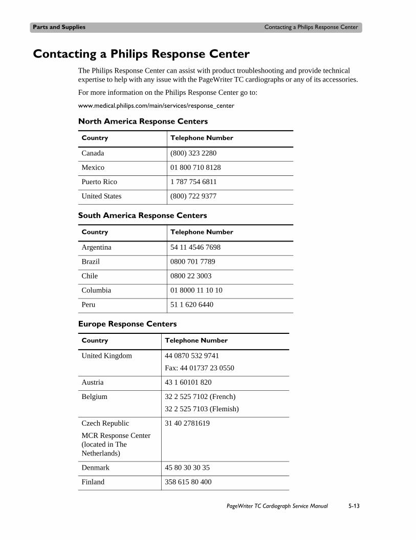
Parts and Supplies Contacting a Philips Response Center
Contacting a Philips Response Center The Philips Response Center can assist with product troubleshooting and provide technical expertise to help with any issue with the PageWriter TC cardiographs or any of its accessories.
For more information on the Philips Response Center go to:
www.medical.philips.com/main/services/response_center
North America Response Centers
Country Telephone Number
Canada (800) 323 2280
Mexico 01 800 710 8128
Puerto Rico 1 787 754 6811
United States (800) 722 9377
South America Response Centers
Country Telephone Number
Argentina 54 11 4546 7698
Brazil 0800 701 7789
Chile 0800 22 3003
Columbia 01 8000 11 10 10
Peru 51 1 620 6440
Europe Response Centers
Country Telephone Number
United Kingdom 44 0870 532 9741
Fax: 44 01737 23 0550
Austria 43 1 60101 820
Belgium 32 2 525 7102 (French)
32 2 525 7103 (Flemish)
Czech Republic
MCR Response Center(located in The Netherlands)
31 40 2781619
Denmark 45 80 30 30 35
Finland 358 615 80 400
PageWriter TC Cardiograph Service Manual 5-13

Parts and Supplies Contacting a Philips Response Center
France 0 810 835 624
Germany 0180 5 47 5000
Greece
MCR Response Center(located in The Netherlands)
31 40 2781619
Hungary
MCR Response Center(located in The Netherlands)
31 40 2781619
Italy 0800 232100
Netherlands 31 40 27 211 27
Norway 47 800 84 080
Poland
MCR Response Center(located in The Netherlands)
31 40 2781619
Romania
MCR Response Center(located in The Netherlands)
31 40 2781619
Russia
MCR Response Center(located in The Netherlands)
31 40 2781619
Slovak Republic
MCR Response Center(located in The Netherlands)
31 40 2781619
Spain 34 90 230 4050
Sweden 46 200 81 00 10
Switzerland 0800 80 3000 (German)
0800 80 3001 (French)
Europe Response Centers
Country Telephone Number
5-14 PageWriter TC Cardiograph Service Manual

Parts and Supplies Contacting a Philips Response Center
Asia Response Centers
Country Telephone Number
Australia 1800 251 400
China 800 810 0038
Hong Kong 852 2876 7578
India 1600 112 444
Indonesia 62 21 7910040, ext 8610
Japan 81 (0)120 095 205
Korea 82 (0)2 3445 9010
Malaysia 1800 886 188
New Zealand 0800 251 400
Philippines 63 2 8162617 ext. 875
Singapore 1800 Philips
Taiwan 0800 005 616
Thailand 66 (0)2 614 3569
Africa and Middle East
Country Telephone Number
All countries
MCR Response Center(located in The Netherlands)
31 40 2781619
PageWriter TC Cardiograph Service Manual 5-15

Parts and Supplies Contacting a Philips Response Center
5-16 PageWriter TC Cardiograph Service Manual

6
2Installing PageWriter TC CardiographSoftware and Enabling Tokens
A software installation procedure takes approximately fifteen minutes to complete.
This chapter provides the following information:Software Upgrades. . . . . . . . . . . . . . . . . . . . . . . . . . . . . . . . . . . . . .6-1Obtaining Software . . . . . . . . . . . . . . . . . . . . . . . . . . . . . . . . . . . . .6-1
Downloading Software Files from Philips InCenter. . . . . .6-1Installing the Software Upgrade . . . . . . . . . . . . . . . . . . . . . . . . . . .6-3
Before You Begin . . . . . . . . . . . . . . . . . . . . . . . . . . . . . . . .6-3Verifying the Software Installation . . . . . . . . . . . . . . . . . . . . . . . . .6-6Enabling Upgrade Options. . . . . . . . . . . . . . . . . . . . . . . . . . . . . . . .6-7
Software UpgradesThe upgrade path for a specific cardiograph is dependent upon the software version that is currently installed on the unit. Follow the same procedure to upgrade the software in an existing working unit or to install software on a new system.
Obtaining Software The software installation procedure requires the use of
a computer with a USB slot
internet access
blank USB memory stick
The following procedure describes how to download the cardiograph software files to the USB memory stick. If the USB memory stick with the applicable software is available, proceed to page 6-3.
Downloading Software Files from Philips InCenterAll software upgrade files may be downloaded from the Philips InCenter web site found at: www.incenter.medical.philips.com. The InCenter site requires an active login and password. Instructions for obtaining a login and password are located on the right side of the main InCenter home page.
6-1

Installing PageWriter TC Cardiograph Software and Enabling Tokens Obtaining Software
To load the software upgrade files to the USB memory stick:
1 Insert the USB memory stick into a compatible slot on a computer or other device.
2 Go to the InCenter site (incenter.medical.philips.com) and enter your login information.
NOTE For information on registering for the InCenter site, see “Using the Philips InCenter Site” on page 1-3.
3 On the top menu bar (top of screen), click on Service. From the drop-down menu, select Software, Software Downloads, and then Diagnostic ECG. The Diagnostic ECG Software Downloads screen appears.
Figure 6-6 InCenter Service Menu
4 Select PageWriter from the side menu (left side of screen). Then select PageWriter TC70, PageWriter TC50, or PageWriter TC30. The applicable PageWriter TC cardiograph software download screen appears.
5 Click the applicable PageWriter TC cardiograph link.
6 On the following software download screen, click the applicable PageWriter TC cardiograph link.
NOTE The Documentation link contains all user documentation (instructions for use, quick reference cards) for the selected software version.
7 The InCenter software download license agreement appears. If you agree to the terms of the agreement, click I agree.
NOTE A message may appear that the Download Manager application needs to be installed. Click as indicated to install the ActiveX control in order to continue with the software download. See the InCenter main page for more information on installing and using ActiveX controls with the InCenter site.
8 Select a file destination and then click Save. The Philips Download Manager dialog appears. The software files are saved to the specified destination. After the files are saved, click Launch. The WinZip Self Extractor dialog appears.
9 Select a destination for the files and then click Unzip. The files are saved to the specified destination.
10 Remove the USB memory stick from the computer or other device and proceed to the next section.
NOTE Once you download software to a USB memory stick, the software installation program will run whenever you insert this USB memory stick into a cardiograph. If you want to use this USB memory stick for copying configuration files or saving log files, delete the SYSINT folder after you have installed the software.
6-2 PageWriter TC Cardiograph Service Manual
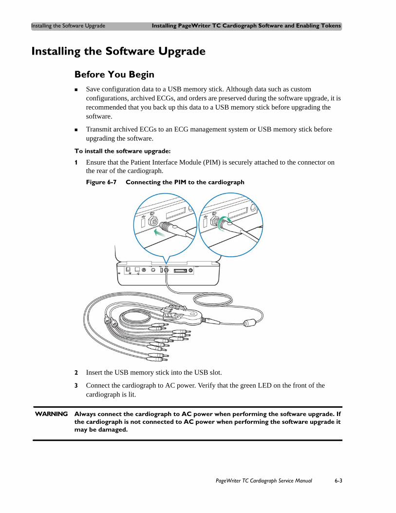
Installing the Software Upgrade Installing PageWriter TC Cardiograph Software and Enabling Tokens
Installing the Software Upgrade
Before You Begin Save configuration data to a USB memory stick. Although data such as custom
configurations, archived ECGs, and orders are preserved during the software upgrade, it is recommended that you back up this data to a USB memory stick before upgrading the software.
Transmit archived ECGs to an ECG management system or USB memory stick before upgrading the software.
To install the software upgrade:
1 Ensure that the Patient Interface Module (PIM) is securely attached to the connector on the rear of the cardiograph.
Figure 6-7 Connecting the PIM to the cardiograph
2 Insert the USB memory stick into the USB slot.
3 Connect the cardiograph to AC power. Verify that the green LED on the front of the cardiograph is lit.
WARNING Always connect the cardiograph to AC power when performing the software upgrade. If the cardiograph is not connected to AC power when performing the software upgrade it may be damaged.
PageWriter TC Cardiograph Service Manual 6-3

Installing PageWriter TC Cardiograph Software and Enabling Tokens Installing the Software Upgrade
4 Press the On/Off button to turn on the cardiograph. The software installation wizard automatically starts, and the Welcome screen appears.
Figure 6-8 Software Installation Wizard Welcome Screen
5 Touch Next.
A message appears notifying you that the cardiograph application must be exited, and that any unsaved ECG data will be lost. If there is any unsaved patient data, touch No to exit the installation wizard and to return to the cardiograph application. Save the patient data, and then restart the installation procedure. If there is no unsaved patient data, touch Yes to continue the installation.
6 A screen appears informing you that the system is collecting information. Once that process is complete, the Select Installation Option screen appears. See Table 6-1 on page 5-5 for a description of each software installation option.
6-4 PageWriter TC Cardiograph Service Manual
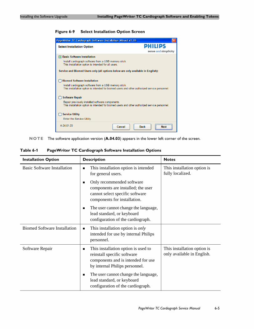
Installing the Software Upgrade Installing PageWriter TC Cardiograph Software and Enabling Tokens
Figure 6-9 Select Installation Option Screen
NOTE The software application version (A.04.03) appears in the lower left corner of the screen.
Table 6-1 PageWriter TC Cardiograph Software Installation Options
Installation Option Description Notes
Basic Software Installation This installation option is intended for general users.
Only recommended software components are installed; the user cannot select specific software components for installation.
The user cannot change the language, lead standard, or keyboard configuration of the cardiograph.
This installation option is fully localized.
Biomed Software Installation This installation option is only intended for use by internal Philips personnel.
Software Repair This installation option is used to reinstall specific software components and is intended for use by internal Philips personnel.
The user cannot change the language, lead standard, or keyboard configuration of the cardiograph.
This installation option is only available in English.
PageWriter TC Cardiograph Service Manual 6-5
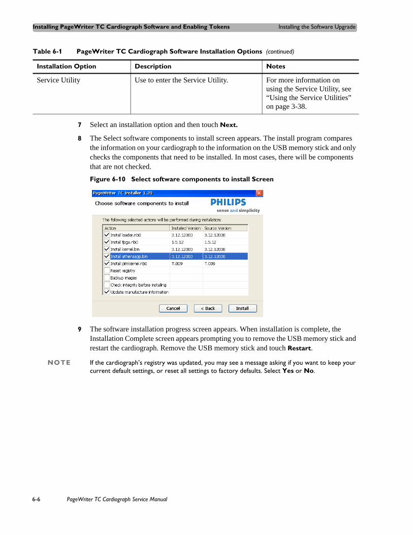
Installing PageWriter TC Cardiograph Software and Enabling Tokens Installing the Software Upgrade
7 Select an installation option and then touch Next.
8 The Select software components to install screen appears. The install program compares the information on your cardiograph to the information on the USB memory stick and only checks the components that need to be installed. In most cases, there will be components that are not checked.
Figure 6-10 Select software components to install Screen
9 The software installation progress screen appears. When installation is complete, the Installation Complete screen appears prompting you to remove the USB memory stick and restart the cardiograph. Remove the USB memory stick and touch Restart.
NOTE If the cardiograph’s registry was updated, you may see a message asking if you want to keep your current default settings, or reset all settings to factory defaults. Select Yes or No.
Service Utility Use to enter the Service Utility. For more information on using the Service Utility, see “Using the Service Utilities” on page 3-38.
Table 6-1 PageWriter TC Cardiograph Software Installation Options (continued)
Installation Option Description Notes
6-6 PageWriter TC Cardiograph Service Manual

Verifying the Software Installation Installing PageWriter TC Cardiograph Software and Enabling Tokens
Figure 6-11 Installation Complete Screen
Verifying the Software InstallationComplete the following procedure to verify that the software application has been successfully installed.
To verify the software installation is complete:
1 From the cardiograph main screen, touch the Setup button.
2 Touch the button next to Service Utilities.
The Setup and Service Utilities screen appears.
3 Check the following information under Software Revisions (upper left corner) on the About the Cardiograph screen to ensure they are at the correct revisions:
– Main Application Revision
– Kernel Revision
– Application Revision
– PIM Kernel Revision
PageWriter TC Cardiograph Service Manual 6-7

Installing PageWriter TC Cardiograph Software and Enabling Tokens Enabling Upgrade Options
Figure 6-12 Software Revisions \
Enabling Upgrade Options The PageWriter TC50 and PageWriter TC30 cardiographs have optional upgrades available, and these upgrade options can be selected either prior to or after initial cardiograph purchase. If an optional upgrade is purchased after the cardiograph is in active use at your facility, the optional upgrade will need to be enabled directly on the cardiograph from the Upgrade Option screen in Setup. For information on purchasing optional upgrades, see “Ordering Options and Upgrades” on page 5-11.
NOTE There are no upgrades available for the PageWriter TC70 cardiograph.
To enable a token/upgrade option:
1 Touch the Setup button on the main toolbar.
2 On the Cardiograph Setup and Service Utilities main menu, touch Upgrade Kit Installation and Software Updates.
3 Touch the Upgrade Option button (top of screen). The Upgrade Option screen appears.
4 The cardiograph serial number appears at the top of the screen. Confirm that the serial number displayed on the screen is the correct serial number of the cardiograph.
5 Enter the Enable Upgrade Option code number (provided with the upgrade kit) into the Enable Upgrade Code field. Touch the Enable Upgrade Option button. The cardiograph automatically restarts and the new upgrade option is enabled.
6-8 PageWriter TC Cardiograph Service Manual

7
1Cart Assembly
Follow the instructions in this chapter to assemble the cart, attach the bin to the cart, and attach the cardiograph to the cart. For information on replacing the rear casters, see the instruction sheet that comes with the replacement kit.
For part ordering information for the replacement kit, see “PageWriter TC70/TC50/TC30 Cardiograph Cart Replacement Parts” on page 5-2.
This chapter provides the following information:Safety Summary. . . . . . . . . . . . . . . . . . . . . . . . . . . . . . . . . . . . . . . .7-1
Safety and Regulatory Symbols Marked on the PageWriter TC70 Cardiograph Cart . . . . . . . . . . . . . . . . . .7-1Safety and Regulatory Symbols Marked on the PageWriter TC50/TC30 Cardiograph Cart . . . . . . . . . . . . .7-3
Assembling the PageWriter TC70 Cardiograph Cart. . . . . . . . . . . .7-3Assembling the PageWriter TC50/TC30 Cardiograph Cart . . . . . .7-7Using the Cart Wheel Positioners and Brake. . . . . . . . . . . . . . . . .7-12
Safety Summary
Safety and Regulatory Symbols Marked on the PageWriter TC70 Cardiograph Cart
Symbol Name Description
Cart Transport Do not transport the cart with the drawer open.
7-1

Cart Assembly Safety Summary
Cart Drawer Weight Limit
Do not place more than 3 kilograms or 6.6 pounds of weight into the cart drawer.
Cart Storage Bin Weight Limit
Do not place more than 3 kilograms or 6.6 pounds of weight into the cart storage bin.
Symbol Name Description
7-2 PageWriter TC Cardiograph Service Manual

Assembling the PageWriter TC70 Cardiograph Cart Cart Assembly
Safety and Regulatory Symbols Marked on the PageWriter TC50/TC30 Cardiograph Cart
Assembling the PageWriter TC70 Cardiograph Cart The PageWriter TC70 cardiograph is available with an optional cart that includes a locking storage drawer, storage bin, and a built-in holder for the PIM (patient interface module). The instructions in this section describe the unassembled cart option. For information on ordering the cart, see "Supplies and Ordering Information" on page 5-7.
To attach the cardiograph to a fully assembled cart, see Step 7 on page 7-6 .
CAUTION Follow the procedure below to ensure that the cardiograph is securely fastened to the cart before use.
Symbol Name Description
Cart Storage Bin Weight Limit
Do not place more than 3 kilograms or 6.6 pounds of weight into the cart storage bin.
Optional Patient Cable Arm
Do not transport the cart with the patient cable arm positioned to the side. Only transport the cart with the patient cable arm positioned to the front of the cart.
PageWriter TC Cardiograph Service Manual 7-3

Cart Assembly Assembling the PageWriter TC70 Cardiograph Cart
Figure 7-1 TC70 Unassembled Cart Kit Contents
To attach the cardiograph to the cart:
1 Insert the beam into the cart base.
7-4 PageWriter TC Cardiograph Service Manual
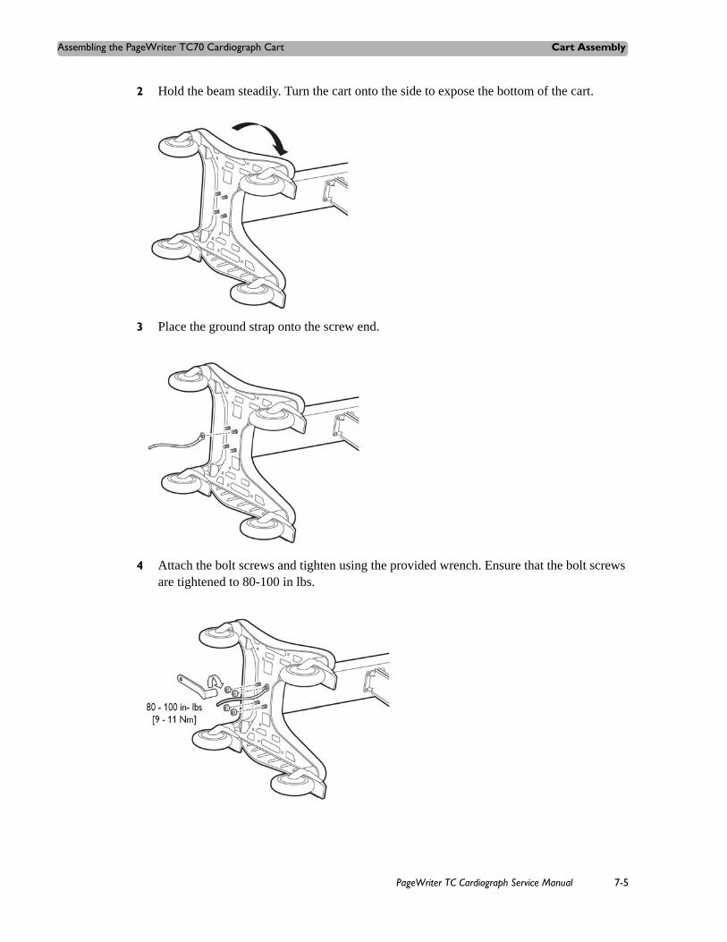
Assembling the PageWriter TC70 Cardiograph Cart Cart Assembly
2 Hold the beam steadily. Turn the cart onto the side to expose the bottom of the cart.
3 Place the ground strap onto the screw end.
4 Attach the bolt screws and tighten using the provided wrench. Ensure that the bolt screws are tightened to 80-100 in lbs.
PageWriter TC Cardiograph Service Manual 7-5

Cart Assembly Assembling the PageWriter TC70 Cardiograph Cart
5 Turn the cart upright.
6 Attach the top shelf to the beam using the provided bolts and wrench. Tighten the bolts to 80-100 in lbs.
7 Align the rear feet of the cardiograph with the rear locking holes on the cart. Align the front feet of the cardiograph with the front screw holes on the cart. Lower the cardiograph onto the cart and snap into place.
7-6 PageWriter TC Cardiograph Service Manual

Assembling the PageWriter TC50/TC30 Cardiograph Cart Cart Assembly
8 Insert the front screws through the bottom of the base, and tighten.
9 Slide the drawer onto the cart as shown.
Assembling the PageWriter TC50/TC30 Cardiograph Cart
The PageWriter TC50 cardiograph and the PageWriter TC30 cardiograph are available with an optional cart that includes a storage bin and a built-in holder for the PIM (patient interface module). A second storage bin is available as an optional accessory. The instructions in this section describe the unassembled cart option. For information on ordering the cart, see "Supplies and Ordering Information" on page 5-7.
To attach the cardiograph to a fully assembled cart, see Step 10 on page 7-11.
CAUTION Follow the procedure below to ensure that the cardiograph is securely fastened to the cart before use.
PageWriter TC Cardiograph Service Manual 7-7

Cart Assembly Assembling the PageWriter TC50/TC30 Cardiograph Cart
Figure 7-2 Unassembled Cart Kit Contents
To attach the cardiograph to the cart:
1 Insert the beam into the cart base.
7-8 PageWriter TC Cardiograph Service Manual

Assembling the PageWriter TC50/TC30 Cardiograph Cart Cart Assembly
2 Hold the beam steadily. Turn the cart onto the side to expose the bottom of the cart.
3 Place the ground strap onto the screw end.
4 Attach the bolt screws and tighten using the provided wrench. Ensure that the bolt screws are tightened to 80-100 in lbs.
PageWriter TC Cardiograph Service Manual 7-9

Cart Assembly Assembling the PageWriter TC50/TC30 Cardiograph Cart
5 Turn the cart upright.
6 Attach the bin to the beam.
7 Insert the bin dividers as shown.
8 Slide out the tray on the top shelf.
7-10 PageWriter TC Cardiograph Service Manual

Assembling the PageWriter TC50/TC30 Cardiograph Cart Cart Assembly
9 Attach the top shelf to the beam using the bolt screws. Tighten the bolts using the provided wrench. Ensure that the bolt screws are tightened to 80-100 in lbs.
10 Align the rear feet of the cardiograph with the rear holes on the cart. Lower the front feet of the cardiograph into the front holes on the cart and push the cardiograph into place. Ensure that the cardiograph is locked into the slot on the front right of the cart.
PageWriter TC Cardiograph Service Manual 7-11

Cart Assembly Using the Cart Wheel Positioners and Brake
11 Insert the screws through the bottom of the base, and tighten.
Using the Cart Wheel Positioners and BrakeBoth cart models include one wheel brake and two wheel positioners. Lock the wheel positioners at all times when using the cart. The wheel positioners keep the cart straight when moving forward or backward, or when turning corners. The wheel positioners also help the cart to maneuver in tight spaces.
To use the cart wheel positioners and brake:
1 Align the front wheels so that they are straight. Step on both wheel positioners. Move the cart forward until the wheels lock into position. The cart will move forward or backward in a straight line.
7-12 PageWriter TC Cardiograph Service Manual

Using the Cart Wheel Positioners and Brake Cart Assembly
2 Step on the gray rear wheel brake to lock the cart wheels. The cart will not move. Step on the wheel brake again to unlock the wheels.
PageWriter TC Cardiograph Service Manual 7-13

Cart Assembly Using the Cart Wheel Positioners and Brake
7-14 PageWriter TC Cardiograph Service Manual

8
2Theory of Operation
This chapter provides the following information:Overview . . . . . . . . . . . . . . . . . . . . . . . . . . . . . . . . . . . . . . . . . .8-2Hardware Logical View . . . . . . . . . . . . . . . . . . . . . . . . . . . . . .8-2
Main Board . . . . . . . . . . . . . . . . . . . . . . . . . . . . . . . . . . . . .8-2Display . . . . . . . . . . . . . . . . . . . . . . . . . . . . . . . . . . . . . . . .8-4Patient Interface Module (PIM) . . . . . . . . . . . . . . . . . . . . .8-4Printer Control (FPGA) . . . . . . . . . . . . . . . . . . . . . . . . . . .8-4Battery (Lithium Ion) . . . . . . . . . . . . . . . . . . . . . . . . . . . . .8-4Keyboard and Buttons . . . . . . . . . . . . . . . . . . . . . . . . . . . .8-4Touch Screen. . . . . . . . . . . . . . . . . . . . . . . . . . . . . . . . . . . .8-5LAN Interface . . . . . . . . . . . . . . . . . . . . . . . . . . . . . . . . . . .8-5Magnetic Card Reader (PS/2) . . . . . . . . . . . . . . . . . . . . . . .8-5Barcode Reader (PS/2) . . . . . . . . . . . . . . . . . . . . . . . . . . . .8-5Smart Card Reader . . . . . . . . . . . . . . . . . . . . . . . . . . . . . . .8-5USB Memory Stick. . . . . . . . . . . . . . . . . . . . . . . . . . . . . . .8-5Wireless LAN Card. . . . . . . . . . . . . . . . . . . . . . . . . . . . . . .8-6Modem Module. . . . . . . . . . . . . . . . . . . . . . . . . . . . . . . . . .8-6
High Level ECG Data Flow and Storage . . . . . . . . . . . . . . . . .8-6Internal Main Archive. . . . . . . . . . . . . . . . . . . . . . . . . . . . .8-9Internal Remote Archive. . . . . . . . . . . . . . . . . . . . . . . . . . .8-9External USB Memory Stick Archives. . . . . . . . . . . . . . . .8-9Rendered ECG Report Prints . . . . . . . . . . . . . . . . . . . . . . .8-9Fax-Rendered ECG Report Print . . . . . . . . . . . . . . . . . . .8-10
Power System Overview . . . . . . . . . . . . . . . . . . . . . . . . . . . .8-11Battery. . . . . . . . . . . . . . . . . . . . . . . . . . . . . . . . . . . . . . . .8-11Voltage Rails . . . . . . . . . . . . . . . . . . . . . . . . . . . . . . . . . . .8-12Power Management . . . . . . . . . . . . . . . . . . . . . . . . . . . . .8-14Battery Power Indicator . . . . . . . . . . . . . . . . . . . . . . . . . .8-15Battery Discharging . . . . . . . . . . . . . . . . . . . . . . . . . . . . .8-16Battery Charging. . . . . . . . . . . . . . . . . . . . . . . . . . . . . . . .8-16Charge Current . . . . . . . . . . . . . . . . . . . . . . . . . . . . . . . . .8-16Battery Information. . . . . . . . . . . . . . . . . . . . . . . . . . . . . .8-16
8-1

Theory of Operation Overview
OverviewAt a system level, the PageWriter TC cardiograph performs acquisition, analysis, printing, storage, and transfer of ECG waveforms and other patient clinical data.
The PageWriter TC cardiograph consists of three major subsystems:
Main board
A main control board built around a powerful embedded processor (Marvell PXA270) with extensive I/O facilities, running Windows CE 5.0. The PageWriter TC cardiograph software application runs on the main board, which supports the display and user-input subsystems.
Print controller
A FPGA-based (Altera Cyclone-I) control circuit, embedded in the main board that provides all the real-time management of the printer.
Patient Interface Module (PIM)
An embedded processor (Marvell PXA270) running Windows CE 5.0, coupled with a signal acquisition board employing Philips proprietary mixed-signal ASIC technology for ECG acquisition. The PIM communicates with the main board through USB.
Hardware Logical View Control of the PageWriter TC cardiograph is provided by application software running on the main board, interacting with numerous hardware and software subsystems. The following are high-level descriptions of these various subsystems.
Main BoardThe main board contains loader software and the Windows CE kernel image in its internal flash memory (64 MB).
At system boot, a basic interface configuration is performed by the loader and then the Windows CE kernel loads. When Windows CE loads, the application launcher runs, verifying system and executable images before loading the main application. All interaction with the user is through the Athena_APP application. This application software is stored in internal Flash memory.
Figure 8-1 illustrates the devices and interfaces provided by the main control board.
8-2 PageWriter TC Cardiograph Service Manual

Hardware Logical View Theory of Operation
Figure 8-1 Devices and Interfaces for the Main Control Board
The main control board (together with interface boards and cables) allows the user to access interfaces including Compact Flash wireless LAN, USB connector, the PS/2 connection for a barcode reader device, the phone connector for a modem, and an RJ45 connector for LAN.
PageWriter TC Cardiograph Service Manual 8-3

Theory of Operation Hardware Logical View
Display The PageWriter TC70 cardiograph display is 1024 x 768 pixels, up to 65536-color TFT LCD with backlight. All display functions are handled by the main control board using the CPU LCD port.
The PageWriter TC50 cardiograph display is 800 x 600 pixels, up to 65536-color TFT LCD with backlight. All display functions are handled by the main control board using the CPU LCD port.
The PageWriter TC30 cardiograph display is 640 x 480 pixels, up to 65536-color TFT LCD with backlight. All display functions are handled by the main control board using the CPU LCD port.
Patient Interface Module (PIM)The PIM is a PXA270-based WinCE subsystem that is connected by the USB to the main control board. It provides real-time data acquisition of ECG signals from electrodes connected to the patient.
Printer Control (FPGA)All data printing is handled by the main control board. The printer control is an Altera FPGA-based control circuit. It accepts printable data, provides basic bitmap imaging operations, and controls the printer head and motor.
Battery (Lithium Ion)The PageWriter TC70 cardiograph only operates with two batteries installed. The PageWriter TC50 and TC30 cardiographs can operate with either one or two batteries installed with software version A.04.00 and higher. Each battery is a lithium ion, 11.1-volt, providing 7.2 amp-hours of current when fully charged.
NOTES When operating the PageWriter TC50/TC30 cardiograph with one battery installed, only use the Philips battery with part number 989803170371. Do not use the battery with Philips part number 989803160981 for one battery operation.
When operating the PageWriter TC50/TC30 cardiograph with two batteries installed, ensure that both batteries contain the same Philips part number. The battery part number identification label is found on the bottom of the battery. The cardiograph cannot operate with two batteries that contain different part numbers. If the cardiograph is operated with two batteries with different part numbers, the cardiograph will display an error message and will not operate.
Keyboard and ButtonsThe PageWriter TC cardiograph includes a laptop-format, PS/2, sealed, full-key action keyboard. Also included are three function buttons, used to turn the cardiograph on and off, for patient ID input, and ECG capture. These three function buttons are designed to support the 1-2-3 ECG capture operation, and also have LED backlights to illustrate their current status.
The keyboard function includes a keyboard matrix, a PS/2 encoding chip on an interface board, and is managed through standard Win CE device drivers.
8-4 PageWriter TC Cardiograph Service Manual
Hardware Logical View Theory of Operation
Touch ScreenThe PageWriter TC cardiograph includes a 5-wire resistive touch screen in front of the LCD panel. The touch screen provides access to all of the cardiograph features. Users simply touch the buttons on the screen to open the different screens and to perform different functions. The touchscreen is controlled by WM9712 (Wolfson) on the main board to sense the touched position, while application software responds accordingly in different screens.
LAN InterfaceThe PageWriter TC cardiograph provides standard LAN capability through a LAN91C111 (SMSC) 10/100M LAN controller. The PageWriter TC cardiograph communicates with the TraceMaster ECG Management System, networked PC or server, or other third party ECG management system through a LAN interface.
Magnetic Card Reader (PS/2)A magnetic card reader is available as an option for the PageWriter TC cardiograph. The reader connects to the cardiograph through an external PS/2 connector and provides ISO and standard encoded magnetic strip support. Manual removal and insertion is required.
NOTE The PS/2 port is not a plug-and-play port. You must attach the magnetic card reader to the port before powering on the cardiograph.
Barcode Reader (PS/2)A barcode reader is available as an option for the PageWriter TC cardiograph. The reader connects to the cardiograph through an external PS/2 connector and provides standard barcode scanning capability. It emulates a keyboard, allowing scanned codes to be presented to the PageWriter TC cardiograph as if they had been typed on the standard keyboard, powered by a PS/2 connection. The barcode reader can be configured using special barcodes. For more information see the Metrologic Barcode Scanner Instructions for Use, available on the User Documentation DVD or can be downloaded from the Philips InCenter site.
NOTE The PS/2 port is not a plug-and-play port. You must attach the barcode reader to the port before powering on the cardiograph.
Smart Card ReaderA Smart Card Reader is available as an option for the PageWriter TC cardiograph. The reader connects to the cardiograph through an external USB connector and provides standard Smart Card reading capability. The PageWriter TC cardiograph can use the Smart Card Reader to obtain patient information.
USB Memory Stick A USB memory stick is available as an option for the PageWriter TC cardiograph. The memory stick connects to the cardiograph through the USB connector located on the right side of the cardiograph (with the front of the cardiograph facing you). The USB memory stick can
PageWriter TC Cardiograph Service Manual 8-5

Theory of Operation High Level ECG Data Flow and Storage
be used to store and transfer ECGs (as XML or PDF) and orders between the cardiograph and a TraceMaster ECG Management System, networked PC or server, or other third party ECG management system.
CAUTION Do not insert a USB memory stick into the cardiograph, or remove a USB memory stick from the cardiograph when the cardiograph is acquiring ECG data from a patient.
CAUTION Only use the USB memory stick to transfer data between the cardiograph and a computer. Do not use the USB memory stick with other devices.
Wireless LAN CardA wireless LAN Card is available as an option for the PageWriter TC cardiograph. The LAN card connects to the cardiograph through the Wireless LAN card slot and provides standard WLAN capability. The PageWriter TC cardiograph communicates with the TraceMaster ECG Management System, networked PC or server, or other third party ECG management system.
Modem ModuleA modem module is available as an option for the PageWriter TC cardiograph. The modem is installed on the I/O module and interfaces to the main board through an RS232 connection, providing standard modem capability. The PageWriter TC cardiograph faxes ECG data to remote receivers or communicates with a TraceMaster ECG Management System, or other third party ECG management system through the modem module.
WARNING Do not connect the modem card to a phone line when the cardiograph is connected to a patient.
High Level ECG Data Flow and Storage General ECG data flow begins with acquisition by the Patient Interface Module (PIM) from electrodes placed on a patient. Data is streamed real-time to the main control board, where it is received into the application buffers in RAM. These buffers are used to present the signal data on the real-time screen. When the user initiates an Auto ECG print, the corresponding10-second segments of the signal data are then copied to the temporary ECG storage memory in RAM.
These 10-second segments are named ECG reports that can be previewed and printed. In the case of Auto mode, the ECG report may be configured to automatically print. An ECG report contains signal data, analysis information, patient demographics, and acquisition information, along with operator and device information. For information on the Philips ECG XML schema, see “Philips ECG XML Information” on page 1-3.
If the Save button on the cardiograph is set to Auto, the ECG report is saved in XML format to the internal main archive. This archive is non-volatile and resides on the internal
8-6 PageWriter TC Cardiograph Service Manual

High Level ECG Data Flow and Storage Theory of Operation
CompactFlash (CF) card. An index file with a CDB extension is also maintained in this archive.
From the internal main archive, the ECG XML data format files can be copied, deleted, previewed, printed, and transferred to other devices. The internal main archive cannot receive ECG XML files from external devices. Retrieved ECG file storage is limited to the internal remote archive.
NOTE PageWriter TC cardiograph-generated ECG XML files comply with the Philips Medical Systems ECG XML Schema version. They incorporate an embedded CRC32 value, which is used to ensure the data integrity of the file.
PageWriter TC Cardiograph Service Manual 8-7

Theory of Operation High Level ECG Data Flow and Storage
Figure 8-2 ECG Flow and Storage
8-8 PageWriter TC Cardiograph Service Manual

High Level ECG Data Flow and Storage Theory of Operation
Internal Main ArchiveThe internal main archive resides on the internal CompactFlash (CF) card, and is used as the primary ECG data repository. This archive is referred to as the Main Archive in the software application. ECG XML files, and a related index file are stored here in the PhilipsArchiveInternal directory. All stored ECG files transition through this archive prior to transfer or copying to other devices, such as the USB memory stick.
Currently, the internal main archive is limited to storing 200 ECGs.
Internal Remote ArchiveThe internal remote archive resides on the internal CompactFlash (CF) card much like the internal main archive. All XML files retrieved from remote sites, such as the TraceMasterVue ECG Management System, reside in this archive until deleted. ECG XML files and related index files are stored in the PhilipsArchiveRemote directory.
Currently, the internal remote archive is limited to a maximum of 100 ECGs.
External USB Memory Stick ArchivesThe external USB memory stick archives reside on a compatible memory stick connected to the USB port. Files can then be transferred to a connected memory stick using the Archive feature of the application software, and are stored in XML format. A CDB file is created and maintained on each compatible USB memory stick when ECG files are transferred to the USB memory stick. Currently, a USB memory stick archive is limited to storing 200 ECGs.
NOTES The PageWriter TC cardiograph only supports the USB memory stick that is shipped with the cardiograph, or that is available for purchase as an optional accessory from Philips Medical Systems. Philips does not guarantee that other USB memory sticks are compatible with the PageWriter TC cardiograph.
When you add or delete compatible ECG XML files from a memory stick (not using the cardiograph), it is recommended that you delete all CDB files prior to reconnecting the memory stick to the cardiograph. In the absence of a CDB file, the cardiograph automatically regenerates the index based on the XML files on the memory stick.
Rendered ECG Report PrintsA rendered ECG report print is a hard copy representation of the ECG data. This includes a high-resolution print of the signal data, and may include configured patient demographics, acquisition information, and other non-signal data elements.
The PageWriter TC cardiograph allows the user to customize the fields on an ECG report print. The report print may consist of one or more continuous pages on perforated thermal media from the printer.
PageWriter TC Cardiograph Service Manual 8-9

Theory of Operation High Level ECG Data Flow and Storage
Figure 8-3 Rendered ECG Report Print Sample
Fax-Rendered ECG Report PrintA fax-rendered ECG report print is equivalent to the rendered ECG report print, as described in the previous section, except it has been adjusted to comply with fax transmission and resolution device requirements. When the user starts a fax transfer, the ECG report is rendered and transmitted to a remote receiving fax machine that has been pre-configured on the cardiograph, using the optional fax and modem. The fax-rendered ECG report print may be stored on the received system end as an electronic file, and not actually used to produce a printed copy.
NOTE No guarantee is made as to the suitability of the faxed ECG for any particular purpose, due to the variability inherent in fax technology.
WARNING Do not connect the modem card to a phone line when the cardiograph is connected to a patient.
8-10 PageWriter TC Cardiograph Service Manual

Power System Overview Theory of Operation
Power System Overview The PageWriter TC cardiograph power system consists of:
One 60-watt AC/DC medical grade power module
One or two 11.1 volt, 7.2amp-hour lithium ion rechargeable batteries
Battery charging circuitry, various voltage regulators, and logic circuitry on the main board
The PageWriter TC cardiograph is designed to run on AC power or battery power. The main board contains a battery charging chip that controls battery charging. The main board has an A/D converter that monitors the voltage of the power supply, and a smart battery controller (part of the charging chip) that monitors the battery charging status.
The major power draws within the PageWriter TC cardiograph is the LCD display backlights, which can draw up to 19 watts, and the thermal printer, which can draw approximately 35 watts. Provisions have been incorporated into the PageWriter TC cardiograph that allows the user to adjust the display brightness. To extend battery life, set the display brightness to the low or medium setting. Also, activate the power save mode (entering standby) to further extend battery life. The printer control circuitry is current-limited for normal printing. However, if print demand is too high, the current limiter will not print the output, resulting in a faded page.
BatteryThe one or two 11.1V rechargable lithium ion batteries provide power to the PageWriter TC cardiograph, and can support full cardiograph functionality without AC when properly charged. Built-in protection circuitry in each pack prevents damage to the battery by overcharging, over discharging, over current, and over temperature.
PageWriter TC Cardiograph Service Manual 8-11

Theory of Operation Power System Overview
Switch
Switch
Switch
Switch
board
l Modem odule
ternal tic Card/ rt card ader
Power itch
Storage Power itch
og Out r Switch
Logic ol Power
itch
Figure 8-4 Power System Block Diagram
Voltage RailsThe following section describes the various voltage rails used on the PageWriter TC cardiograph.
Vin
The DC voltage is supplied from the AC/DC adapter through fuses and diodes. The voltage level is between 13.95 to 14.43 VDC, with a maximum power output of 80 watts. This voltage is not monitored.
VCC_Battery 1/2
The battery voltages range between 9.0V to 12.6V. Discharge current (on each battery) is limited to a continuous 6.0 amps, with a 6.3 to 8.7 amp limit for short periods. These two voltages are monitored through the battery charger.
(CPU)
VCC_BATT
VCC_Motor
PHD_5V
CF2_nVCCD1
VCC_CORE
VCC_IO_PLD
VCC_INT_PLD3.3V
CF2_VCC
(FPGA)
(CPU)
(CPU)
5V_PWR_ON
VCC_RTC
PWR_OUT
FLASH, SDRAM, Intel 270,SM501, Buffer, Ethernet, Touch screen, LCD, LED, AC97 ,RS232, CF card, Wi-FI, FPGA, ADC, SDIO card, modem
5V
3.3V
USB_nRSTAC97_nRESET
3.3V
3.3V
3.3V
5V
3.3V
5V
VCC_BATT (3.3V)
PHD_26V_ON
LOAD_PWR
3A Max charging current
3.3V
3.3V
PWR_EN
SYS_EN
5V
VCC_1P8
5V
12V BACKLIGHT INVERTER
15" LCD: NEC NL10276BC30-1810" LCD: NEC NL8060BC26-28 6" LCD: AUO G065VN01
LOAD_PWR
VBAT2 (9~12.6V)
Vin
VCC_PRNHD
110~240V,50~60 Hz
AC
VM (26V)
External AC/DC Module
(MW159RA1549F02)
SW RGL TR(LM2588S-Adj)
POWER SWITCH
SW RGLTR CONTLTC1778EGN-1
VBAT1 (9~12.6V)
Current limit /switch circuit
Printer Motor Driver(L6219DS)
Printer Head
Li-ion Battery 1ME202CJ
(11.1V, 7100mAH)
Li-ion Battery 2ME202CJ
(11.1V, 7100mAH)
Daul Smart Battery System Manager(LT1760)
SMB
US
SMBUS
5V
PWM RegulatorLTC1628
(5V Current: 4A Max3.3V Current: 4A Max)
VCC_1P5Regulator AdjLTC3406
VCC_PLL
VCC_SRAM
RegulatorLTC3445
LT3470
SMBUS
Printer Motor
Battery discharging
3.3V
FPGA
SM501
Intel PXA270
BKL_PWR_ON
BOOST_PWR_ON
To PXA270
SYS_EN
Regulator AdjLTC3404
MOSFET Power switch
MOSFETPower Switch
MOSFETPower Switch
PWR_ON
USB1
USB2
USB3
USB4
Key
5V
5V
5V
5V
USB1_nEN
USB2_nEN
USB3_nEN
USB4_nEN
InternaM
Modem_PWR_ON
ExMagne
SmaRe
EXT_PS2_PWR_ON
3.3V SDIOSw
SDIO_PWR_ON
3.3V Int. CFCard
Sw
CF1_PWR_ON
3.3V AnalPowe
3.3V LCD
ContrSw
Panel_PWR_ON
3.3V
3.3V
3.3V
Flash Memory
PWR_EN
3.3V
LAN Controller(LAN91C111)
LAN_RST
GC_nRST
3.3V USB_Hub(USB2504)
UI_PWR_ON
3.3V Touchscreen/AC97 Codec(Wolfson WM9712LGEFL/RV )
DAC_SHDN
CHG_VDDS_ON
nCHG_MODE_CTL
Ext. CF socketpower switch
CF2_nVCCD0
CF2_nOC
CF2_nSHDN
FuseSwitch
PWR_ON
PRT_5V_ON
MOSFET Power switch
(CPU)
(CPU)
(CPU)
(CPU)
(CPU)
(CPU)
(FPGA)
(FPGA)
(FPGA)
(FPGA)
(FPGA)
(FPGA)
(FPGA)
(FPGA)
(FPGA)
(FPGA)
(FPGA)
(FPGA)
(FPGA)
(CPU) (CPU) (CPU)
Real Time clock
Power Option
MOSFETPower Switch
LT1761
CPLD
VCC_BACKUP
VCC_PLD
8-12 PageWriter TC Cardiograph Service Manual

Power System Overview Theory of Operation
Load_PWR
The voltage is supplied by Vin and the battery. Its range is between 9.0V to 14.43V. This voltage is monitored.
+3.3V
Output from regulator U1401 (LTC1628). The input to this regulator is from Loads_PWR and can supply 3.3V at up to 4.0A of current. This voltage is monitored.
VCC_RTC
Output from regulator U1403 (LT3470) for the real timer and power sequence circuit. The voltage level is 3.3V, and can provide up to 200mA of current. This voltage is not monitored.
VCC_Core (+1.5V)
Output from regulator U1202 (LTC3445) which is 1.5V core power for the embedded processor. The input to this regulator is from the 3.3V supply and can supply up to 600mA of current. This voltage is monitored.
VCC_SRAM (+1.1V)
Output from regulator U1202 (LTC3445), which is 1.1V SRAM power for the embedded processor. The input to this regulator is from the +3.3V supply, and can supply up to 50mA of current. This voltage is not monitored.
VCC_PLL (+1.3V)
Output from regulator U1202 (LTC3445), which is 1.3V PLL power for the embedded processor. The input to this regulator is from the +3.3V supply, and can supply up to 50mA of current. This voltage is not monitored.
VCC_1P8 (+1.8V)
Output from regulator U1201 (LTC3404), which is 1.8V power for the flash memory core. The input to this regulator is from the +3.3V supply, and can supply up to 600mA of current. This voltage is monitored.
VCC_1P5 (+1.5V)
Output from regulator U1203 (LTC3406), which is 1.5V core power for the FPGA. The input to this regulator is from the +3.3V supply, and can supply up to 600mA of current. This voltage is monitored.
VCC_INT_PLD (+1.8V)
Output from regulator U1402 (LT1761), which is 1.8V power for the CPLD core. The input to this regulator is from the +3.3V supply, and can supply up to 100mA of current. This voltage is not monitored.
PageWriter TC Cardiograph Service Manual 8-13

Theory of Operation Power System Overview
+5V
Output from regulator U1401 (LTC1628) which supplies all the 5.V power to the system. Input is from Load_PWR, and output is 4.87 to 5.24 VDC with a maximum current of 3A. This voltage is monitored.
USB4_VCC
Output from switch U702 (LM3525) which supplies the PIM power. Input is from +5V, and output is 5V with maximum current of 1.0A. This voltage is monitored.
VM
Output from regulator U1501 (LM2588), which supplies +26V power to the print head and motor. This voltage is not monitored.
VCC_PRNHD
Output from switch Q1503, which supplies +26V power to the print head. It is controlled by FPGA on the main board. VCC_PRNHD provides power only when a print session starts. Otherwise, VCC_PRNHD does not provide power. This voltage is monitored by FPGA.
VCC_MOTOR
Output from switch Q1501, which supplies +26V power to the print motor. It is controlled by FPGA on the main board. VCC_MOTOR provides power only when a print session starts. Otherwise, VCC_MOTOR does not provide power. This voltage is not monitored.
VCC_BKLGT
Output from regulator U1504 (LTC3780), which supplies display backlight. Input is from Load_PWR and output is 12V with a maxim current of 3.5A.
Power Management
Power Modes Control
The system host processor controls transition between power modes, including:
Entering Standby if no activity is detected for a preset period of time (upon configuration).
Powering off the unit if no activity is detected for a preset period of time (upon configuration)
Entering Standby or shut down, when battery remaining capacity is below preset level and no AC power is applied
8-14 PageWriter TC Cardiograph Service Manual

Power System Overview Theory of Operation
Battery Charging Logic
Battery charging is controlled by the charger chip. The charger chip can:
Charge the battery when the system is in off mode, Standby, and run mode.
Alert the user when charging is recommended for the battery, when the system is powered by battery only.
Battery Power IndicatorThe battery power indicator appears on the Status Bar and is always visible. The indicator displays the current battery power level. The cardiograph can operate on AC power while the batteries are charging.
Figure 8-5 Battery Power Indicator on the Status Bar
You can touch the Battery Power Indicator on the Status Bar to ensure that the batteries are fully charged. The Battery Status Information window appears. This window provides detailed information on the status of the cardiograph batteries.
NOTE The battery indicator may not always accurately reflect the true charge state of the battery due to the age of the battery, or due to failure to perform specified battery maintenance.
Table 8-1 describes the battery level indicator.
A Battery level indicator
A
Table 8-1 Battery Level Indicator Information (icon on Status Bar)
Icon on Status Bar Battery Level
Fully Charged Battery
75% power capacity
50% power capacity
PageWriter TC Cardiograph Service Manual 8-15

Theory of Operation Power System Overview
Battery DischargingIf no AC power is applied to the system, when the batteries are discharged to the 15% level, the PageWriter TC cardiograph automatically enters Standby and alerts the user to apply AC power. When the batteries are discharged to a 12% level, the PageWriter TC cardiograph automatically shuts down.
NOTE The battery will continue to discharge when the cardiograph is not in use, or if the battery is stored outside of the cardiograph.
Battery ChargingWhen the AC power cord is plugged in, the battery begins to charge. Check the charging status through the Service Utilities. See “Using the Service Utilities” on page 3-38 for more information.
Charge CurrentWhen AC power is applied to the cardiograph, the batteries are charged at maximum 3A total current. Check the charging current through the Service Utilities. See “Using the Service Utilities” on page 3-38 for more information.
Battery InformationBattery information is sent from the battery charger, U1301. This information is then sent to the host processor via SMBUS, and can be viewed from the Service Utilities screen. See “Using the Service Utilities” on page 3-38 for more information.
Low Battery Power:
Red battery icon appears when power level is below 25%
Cardiograph beeps and an error message appears until the unit is plugged into AC power (audio feature may be disabled)
Tap the icon to see how many minutes are left of operating battery power
If overall battery power is below 15% and the cardiograph is in Standby, when the On/Standby button ( ) is pressed it will flash green five times and the cardiograph will be unable to return to active use. Plug the cardiograph into AC power to recharge the batteries.
No or Dead Battery
Table 8-1 Battery Level Indicator Information (icon on Status Bar)
Icon on Status Bar Battery Level
8-16 PageWriter TC Cardiograph Service Manual

A
1Specifications
Technical Specifications
PageWriter TC70 Cardiograph ECG Acquisition Simultaneous Lead Acquisition (12 leads standard; up to 16 leads optional)
Rhythm Strips (12 leads standard; up to 16 leads optional)
Event Marking (15 independent events can be marked for later review and analysis)
Full Disclosure (12 leads standard; 16 leads optional)
Timed ECG
PageWriter TC50 Cardiograph ECG Acquisition Simultaneous Lead Acquisition (12 leads standard; up to 16 leads optional)
Rhythm Strips (12 leads standard; up to 16 leads optional)
Event Marking (10 independent events can be marked for later review and analysis)
Full Disclosure (12 leads standard; 16 leads optional)
Timed ECG
PageWriter TC30 Cardiograph ECG Acquisition Simultaneous Lead Acquisition (12 leads standard; up to 16 leads optional)
Rhythm Strips (12 leads standard; up to 16 leads optional)
Event Marking (6 independent events can be marked for later review and analysis)
Full Disclosure (12 leads standard; 16 leads optional)
Timed ECG
PageWriter TC70 Keyboard Full alphanumeric capability QWERTY keyboard
A-1

Specifications Technical Specifications
PageWriter TC50/TC30 Keyboard 65 button, standard full alphanumeric capability keyboard
Support for special characters
Optional, silicon-based flexible membrane keyboard cover that protects keyboard from particulate and liquid ingress
PageWriter TC70 Touch screen Display 1024 x 768 pixel resolution
30.4 cm x 22.8 cm (11.96 x 6.22 in) color liquid crystal touch screen display with backlight
PageWriter TC50 Touch screen Display 800 x 600 pixel resolution
21.1 cm x 15.8 cm (8.30 x 8.97 in) color liquid crystal touch screen display with backlight
PageWriter TC30 Touch screen Display 640 x 480 pixel resolution VGA with 18-bit/pixel color depth
5-wire, resistive touch screen
13.33 cm wide x 9.9 cm high (5.25 inches wide x 3.9 inches high) color liquid crystal touch screen display with backlight
Patient Interface Module Remote, microprocessor-controlled module
ECG button with signal quality indicator allows user to take ECGs from the bedside
Patient Interface Module Signal Acquisition 8,000 samples per second per electrode/lead for standard 12 or up to 16 leads
Signal Processing/Acquisition
Sampling Rate
500 samples per second per electrode/lead
12 bit A/D conversion provides down sampled 5µV resolution, 500 samples per second measurement with no channel to channel skew
A-2 PageWriter TC Cardiograph Service Manual
Technical Specifications Specifications
Auto Frequency Response 0.05-150 Hz, 0.15-150 Hz, 0.5-150 Hz0.05-100 Hz, 0.15-100 Hz, 0.5-100 Hz0.05-40 Hz, 0.15-40 Hz, 0.5-40 Hz
Rhythm Frequency Response 0.05-40 Hz, 0.05-100 Hz, 0.05-150 Hz0.15-40 Hz, 0.15-100 Hz, 0.15-150 Hz
Minimum Amplitude or Value of Patient Physiological Signal
CAUTION The QRS wave must be a minimum of 100µV peak to peak or greater for the lead’s complex to be measured. The operation of the cardiograph below this value may cause incorrect ECG analysis.
Filters AC noise (50 or 60 Hz)
Baseline Wander
Artifact
Printer
Printer Resolution
High-resolution, digital-array printer using thermal-sensitive paper
200 dpi (voltage axis) by 500 dpi (time axis) at 25 mm/sec
Report Formats
Exam Profiles
Up to 12 configured Exam Profiles can be specified
12 Lead Report Formats
3x4 (1R, 3R)
3x4, 1R 8ST
3x4, 1R 10ST
6x2
Panoramic 12 (Cabrera sequence only)
PageWriter TC Cardiograph Service Manual A-3

Specifications Technical Specifications
12x1
Extended Measurements
PageWriter TC70/TC50 16 Lead Report Formats
3x5 (1R, 3R)
3x5, 1R ST
4x4 (1R)
4x4 1R, ST
Extended Measurements
STEMI Diagnostic Aids
Graphical ST Vector
Polar ST Maps with frontal and transverse planes available on two ECG report formats
STEMI-CA criteria
Critical Values
Rhythm Report Formats
Rhythm (up to 12, or up to optional 16 selected leads)
Battery Operation
SMBus compliant batteries
Voltage
11.1 VDC (nominal), 7100 mAH (per battery)
Current
6.0 A max per battery (continuous)
Power
54 W max per battery (continuous)
PageWriter TC70/TC50/TC30 Two Battery Operating Capacity
45 minutes of continuous Rhythm printing, or a maximum of 237 individual sheets of ECG recording paper
A-4 PageWriter TC Cardiograph Service Manual

Technical Specifications Specifications
PageWriter TC50/TC30 One Battery Operating Capacity
The battery capacity for the PageWriter TC50 or PageWriter TC30 cardiograph with a single battery installed using the battery with Philips part number 989803170371, is 30 minutes of continuous Rhythm printing, or 30 total ECG reports
Status Display
Full Charge Capacity (mAHR)
Remaining Capacity (%)
Temperature (deg C)
Discharge Current (mA)
Charge Current (mA)
Low battery audio and visual alerts
Recharge
Less than 4 hours if cardiograph is in Standby (not in active use) to at least 95% capacity
Less than 8 hours if the cardiograph is in active use to at least 95% capacity
Ethernet LAN Network Connection 10/100 Base-T IEEE 802.3 Ethernet via RJ45 connector (standard)
Wireless LAN Network Connection Optional software required for wireless LAN connection. Wireless LAN connection is
802.11a/g/i, WPA, WPA2, and CCX compatible.
FAX Capability (optional) Group 3, Class 1 or 2 fax
Modem V.90, K56flex, enhanced V.34, V.32bis, V.32, V.22bis and below
Barcode Reader (optional) Reads Code 39 (standard and full ASCII)
Flexible field data entry
PageWriter TC Cardiograph Service Manual A-5
Specifications Technical Specifications
Magnetic Card Reader (optional) Reads cards adhering to ISO 7810, 7811-1, -2, -3, -4, -5
Smart Card Reader (optional) Reads cards adhering to ISO/IEC 7816
Smart Card Reader (optional) Reads cards adhering to ISO/IEC 7816, and EMV 3.1.1
Supports SLE 4418/28 and SLE 4443/42
ECG Storage XML File Format in version 1.03, 1.04, 1.04.01, and 1.04.02
Up to 200 ECGs to internal flash memory
Up to 200 ECGs per USB Memory Stick (optional)
Full fidelity at 500 Hz of all 10 seconds of all 12 leads
Orders Up to 200 pending orders can be stored on the cardiograph
ECG File Formats XML and XML SVG
Power and Environment
PageWriter TC70 Cardiograph AC Adapter
Input voltage: 100 to 240 VAC
Input voltage frequency: 50 to 60 Hz
Input current: 1.4A - 0.7A
Output: 15 Volts DC, 5.33A, 80W
PageWriter TC50/TC30 Cardiograph AC Input Voltage
Input voltage: 100 to 240 VAC
Input voltage frequency: 50 to 60 Hz
A-6 PageWriter TC Cardiograph Service Manual

Technical Specifications Specifications
Input current: 1.2A
PageWriter TC50/TC30 Cardiograph AC Output Voltage
Output: 15 Volts DC, 4.0A, 60W
PageWriter TC70/TC50/TC30 Cardiograph Environmental Operating Conditions 10° to 40 °C (50° to 104°F)
10% to 90% relative humidity (non-condensing)
Up to 4,247m (14,000 ft.) altitude, 597 hPA
PageWriter TC70/TC50/TC30 Cardiograph Environmental Storage Conditions -20° to 50 °C (-4° to 122°F)
10% to 90% relative humidity (non-condensing)
Up to 4,572 m (15,000 ft.) altitude, 572 hPA
TC30 Cardiograph Dimensions 310 mm wide x 405 mm deep x 205 mm height (12.20 inches wide x 15.94 inches deep x
8.07 inches height)
TC30 Cardiograph Weight 8.6 kg (19 lb) including accessories (2 batteries installed, 200 sheets of ECG recording
paper, Patient Interface Module, patient data cable, AC power cord)
PageWriter TC50 Cardiograph Dimensions 405 mm wide x 310 mm deep x 130 mm height (15.94 inches wide x 12.2 inches deep x
5.11 inches height) with top cover in down position
PageWriter TC50 Cardiograph Weight 13 kg (28 lb) including accessories
PageWriter TC70 Cardiograph Dimensions 330 mm length x 405 mm width x 135 mm height (12.99 inches wide x 15.94 inches deep x
5.31 inches height) with top cover in down position
PageWriter TC Cardiograph Service Manual A-7

Specifications Safety and Performance
PageWriter TC70 Cardiograph Weight 9 kg (19.84 lb) including accessories
PageWriter TC70/TC50/TC30 Cardiograph Shipping Container Weight Maximum shipping weight of packaged PageWriter TC cardiograph (including all
accessories) is 17.1 kg (37.69 lb)
Safety and PerformanceMeets the following requirements for safety and performance:
IEC 60601-1: 1988 +A1:1991 +A2:1995 Medical electrical equipment – Part 1: General requirements for Safety (Includes national differences for standards AS/NZS 3200.1.0: 1998, CAN/CSA-C22.2 No. 60601-1-M90 +B: 90 +S1: 94, EN 60601-1: 1990 +A1: 1993 +A11: 1993 +A12: 1993 +A13: 1996, JIS T 0601-1: 1999, UL 60601-1: 2003)
IEC 60601-2-25: 1993 +A1:1999 Particular requirements for the safety of electrocardiographs (Includes national differences for standards AS/NZS 3200.2.25: 1993, CAN/CSA-C22.2 No. 60601-2-25: 1994 +A1: 2002, EN 60601-2-25: 1995 + A1: 1999)
IEC 60601-2-51: 2003 Particular requirements for safety, including essential performance, of recording and analyzing single channel and multi-channel electrocardiographs (Includes national differences for standards CAN/CSA-C22.2 No. 60601-2-51: 2004, EN 60601-2-51: 2003)
IEC/EN 60601-1-2 2001: 2nd ed Electromagnetic compatibility- Requirements and tests
AAMI EC11: 1991 (R: 2001) Diagnostic Electrocardiographic Devices
Classification (IEC 60601-1)
PageWriter TC50/TC30 Cardiograph Class I (Internally Powered)
PageWriter TC70 Cardiograph Class II (Internally Powered)
Symbol Meaning
ECG physio isolation is type CF, defibrillator proof. Suitable for all patient applications including direct cardiac application. System is in continuous operation.
IPX0 Cardiograph has ordinary protection against the entry of liquids.
IPX4 The PIM (patient interface module) is protected against splashing water. Water splashed against the PIM from any direction shall have no harmful effect.
A-8 PageWriter TC Cardiograph Service Manual

Electromagnetic Compatibility (EMC) Specifications
WARNING When using additional peripheral equipment powered from an electrical source other than the cardiograph, the combination is considered to be a medical system. It is the responsibility of the operator to comply with IEC 60601-1-1 and test the medical system according to the requirements. For additional information contact Philips Medical Systems.
Electromagnetic Compatibility (EMC)Electronic devices can either generate or receive electromagnetic interference. The PageWriter TC70/TC50/TC30 cardiograph have been evaluated for electromagnetic compatibility (EMC) with the appropriate accessories according to Medical Collateral standard IEC 60601-1-2, Edition 2 (with exceptions noted in proceeding tables). This IEC standard has been adopted in the European Union as the European Norm, EN 60601-1-2, Edition 2.
WARNING Radio frequency (RF) interference from nearby transmitting devices may degrade performance of the electronic equipment. Electromagnetic compatibility with surrounding devices should be assessed prior to using the equipment.
WARNING Fixed, portable, and mobile radio frequency communications equipment can also affect the performance of electrical equipment. See your Service Provider for assistance with the minimum recommended separation distance between RF communications equipment and the PageWriter TC cardiograph.
WARNING The use of accessories and cables other than those specified in the Philips PageWriter TC cardiograph service and user documentation can result in increased emissions or decreased immunity of the system.
WARNING The PageWriter TC cardiograph should not be used next to or stacked on top of other equipment. If you must stack the product, you must check that normal operation is possible in the necessary configuration before the product is used.
Reducing Electromagnetic Interference
The PageWriter TC70/TC50/TC30 cardiograph and accessories may become sensitive to interference from other RF energy sources including power lines. RF energy sources include
Cardiograph is not suitable for use in the presence of flammable anesthetic mixture with air, oxygen, or nitrous oxide.
System is continuous operation.
PageWriter TC Cardiograph Service Manual A-9

Specifications Electromagnetic Compatibility (EMC)
other medical devices, wireless devices, information technology equipment, and radio/television transmission. Should interference be encountered, as demonstrated by artifact on the ECG trace, unintended change on operating state, or unit lockup, attempt to locate the source by assessing:
if the interference is intermittent or constant?
does the interference occur only in certain locations?
does the interference occur only when in close proximity to certain medical devices?
does the ECG signal quality change dramatically when the AC power cord is unplugged?
Once the source of the interference is located, attempt to attenuate the EMC coupling path by distancing the cardiograph from the source of the interference as much as possible. If further assistance is needed, contact the Philips Response Center nearest you.
Table A-1 PageWriter TC50/TC30 Cardiograph Guidance and Manufacturer’s Declaration: Electromagnetic Emissions
The PageWriter TC50/TC30 cardiograph is intended for use in the electromagnetic environment specified in the table below. The customer or the user of the PageWriter TC50/TC30 cardiograph should assure that it is used in such an environment.
Emissions Test Compliance Electromagnetic Environment: guidance
RF EmissionsCISPR 11
Group 1 The PageWriter TC50/TC30 cardiograph uses RF energy only for its internal function. Therefore, its RF emissions are very low are not likely to cause any interference in nearby electronic equipment.
RF EmissionsCISPR 11
Class B The PageWriter TC50/TC30 cardiograph is suitable for use in all establishments, including domestic establishments and those directly connected to the public low-voltage power supply network that supplies buildings used for domestic purposes.
Harmonic EmissionsIEC 61000-3-2
Class A
Voltage fluctuations/flicker emissionsIEC 61000-3-3
Complies
Table A-2 PageWriter TC70 Cardiograph Guidance and Manufacturer’s Declaration: Electromagnetic Emissions
The PageWriter TC70 cardiograph is intended for use in the electromagnetic environment specified in the table below. The customer or the user of the PageWriter TC70 cardiograph should assure that it is used in such an environment.
Emissions Test Compliance Electromagnetic Environment: guidance
RF EmissionsCISPR 11
Group 1 The PageWriter TC70 cardiograph uses RF energy only for its internal function. Therefore, its RF emissions are very low and are not likely to cause any interference in nearby electronic equipment.
A-10 PageWriter TC Cardiograph Service Manual

Electromagnetic Compatibility (EMC) Specifications
RF EmissionsCISPR 11
Class A The PageWriter TC70 cardiograph is suitable for use in all establishments other than domestic and those directly connected to the public low-voltage power supply network that supplies buildings used for domestic purposes.
Harmonic EmissionsIEC 61000-3-2
Class A
Voltage fluctuations/flicker emissionsIEC 61000-3-3
Complies
Table A-2 PageWriter TC70 Cardiograph Guidance and Manufacturer’s Declaration: Electromagnetic Emissions (continued)
The PageWriter TC70 cardiograph is intended for use in the electromagnetic environment specified in the table below. The customer or the user of the PageWriter TC70 cardiograph should assure that it is used in such an environment.
Emissions Test Compliance Electromagnetic Environment: guidance
Table A-3 Guidance and Manufacturer’s Declaration: Electromagnetic Immunity
The PageWriter TC70/TC50/TC30 cardiographs are intended for use in the electromagnetic environment specified below. The customer or the user of the PageWriter TC cardiograph should assure that it is used in such an environment.
Immunity Test IEC 60601 Test Level
Compliance Level
Electromagnetic Environment: guidance
Electrostatic Discharge (ESD)IEC 61000-4-2
+/- 6 kV contact
+/- 8 kV air
+/- 6 kV contact
+/- 8 kV air
Floors should be constructed of wood, concrete, or ceramic tile. If floors are covered with synthetic material, the relative humidity should be at least 30%.
Electrical Fast transient/burst
IEC 61000-4-4
+/- 2 kV for power supply lines
+/- 1 kV for input/output lines
+/- 2 kV for power supply lines
+/- 1 kV for input/output lines
Mains power quality should be that of a typical commercial or hospital environment.
Surge
IEC 61000-4-5
+/- 1 kV differential mode
+/- 2 kV common mode
+/- 1 kV differential mode
+/- 2 kV common mode
Mains power quality should be that of a typical commercial or hospital environment.
PageWriter TC Cardiograph Service Manual A-11

Specifications Electromagnetic Compatibility (EMC)
Voltage dips, short interruptions and voltage variations on power supply input lines
IEC 61000-4-11
<5% UT
(>95% dip in UT) for 0.5 cycle
40% UT
(60% dip in UT) for 5 cycles
70% UT
(>30% dip in UT) for 25 cycles
<5% UT
(>95% dip in UT) for 5 seconds
<5% UT
(>95% dip in UT) for 0.5 cycle
40% UT
(60% dip in UT) for 5 cycles
70% UT
(>30% dip in UT) for 25 cycles
<5% UT
(>95% dip in UT) for 5 seconds
Mains power quality should be that of a typical commercial or hospital environment. If the user of the PageWriter TC cardiograph requires continued operation during power mains interruptions, it is recommended that the PageWriter TC cardiograph be powered from an uninterruptable power supply or a battery.
Power frequency (50./60 Hz) magnetic field
3 A/m Complies Power frequency magnetic fields should be at levels characteristic of a typical location in a typical commercial or hospital environment.
Note: UT is the a.c. mains voltage prior to application of the test level.
Table A-3 Guidance and Manufacturer’s Declaration: Electromagnetic Immunity (continued)
The PageWriter TC70/TC50/TC30 cardiographs are intended for use in the electromagnetic environment specified below. The customer or the user of the PageWriter TC cardiograph should assure that it is used in such an environment.
Immunity Test IEC 60601 Test Level
Compliance Level
Electromagnetic Environment: guidance
A-12 PageWriter TC Cardiograph Service Manual

Electromagnetic Compatibility (EMC) Specifications
Table A-4 Guidance and Manufacturer’s Declaration: Electromagentic Immunity (continued)
The PageWriter TC70/TC50/TC30 cardiograph are intended for use in the electromagnetic environment specified below. The customer or the user of the PageWriter TC cardiograph should assure that it is used in such an environment.
Immunity Test IEC 60601Test Level
Compliance Level
Electromagnetic Environment: guidance
Portable and mobile RF communications equipment should be used no closer to any part of the PageWriter TC cardiograph, including cables, than the recommended separation distance calculated from the equation applicable to the frequency of the transmitter.
Recommended separation distance
Where P is the maximum output power rating of the transmitter in watts (W) according to the transmitter manufacturer and d is the recommended separation distance in meters (m).
Field strengths from fixed RF transmitters, as determined by an electromagnetic site surveya, should be less than the compliance level in each frequency rangeb.
Interference may occur in the vicinity of equipment marked with the following symbol:
Conducted RF
IEC 61000-4-6
3 Vrms
150 kHz to 80 MHz
3 Vrms
Radiated RF
IEC 61000-4-3
3 V/m80 MHz to 2,5 GHz
3 V/m
Note 1: At 80 MHz and 800 MHz, the higher frequency range applies.
Note 2: These guidelines may not apply in all situations. Electromagnetic propagation is affected by absorption and reflection from surfaces, objects, and people.
d 1.2 P=
d 1.2 P=
d 2.3 P=
80 MHz to 800 MHz
800 MHz to 2,5 GHz
PageWriter TC Cardiograph Service Manual A-13

Specifications Electromagnetic Compatibility (EMC)
a. Field strengths from fixed transmitters, such as base stations for radio (cellular/cordless) telephones and landmobile radios, amateur radio, AM and FM radio broadcast and TV broadcast cannot be predicted theoreticallywith accuracy. To assess the electromagnetic environment due to fixed RF transmitters, an electromagneticsite survey should be considered. If the measured field strength in the location in which the PageWriter TCcardiograph are used exceeds the applicable RF compliance level above, the PageWriter TC cardiographshould be observed to verify normal operation. If abnormal performance is observed, additional measures maybe necessary, such as re-orienting or relocating the PageWriter TC cardiograph.
b. Over the frequency range 150 kHz to 80 MHz, field strengths should be less than 3 V/m.
Table A-5 Recommended Separation Distances Between Portable and Mobile RF Communications Equipment and the PageWriter TC Cardiograph: for equipment and systems that are not life-supporting
The PageWriter TC70/TC50/TC30 cardiographs are intended for use in the electromagnetic environment in which radiated RF disturbances are controlled. The customer or the user of the PageWriter TC cardiograph can help to prevent electromagnetic interference by maintaining a minimum distance between portable and mobile RF communications equipment (transmitters) and the PageWriter TC cardiograph as recommended below, according to the maximum output power of the communications equipment.
Rated Maximum Output Power of Transmitter (W) Separation Distance According to Frequency of Transmitter (m)
0.01
150 KHz to 800 KHz 800 MHz to 2.5 GHz
d = 1.2 d = 2.3
0.1 m 0.2 m
0.1 0.4 m 0.7 m
1 1.2 m 2.3 m
10 4.0 m 7.0 m
100 12.0 m 23.0 m
For transmitters rated at a maximum output power not listed above, the recommended separation distance d in meters (m) can be estimated using the equation applicable to the frequency of the transmitter, where P is the maximum output power rating of the transmitter in watts (W) according to the transmitter manufacturer.
Note 1: At 80 MHz and 800 MHz, the separation distance for the higher frequency range applies.
Note 2: These guidelines may not apply in all situations. Electromagnetic propagation is affected by the absorption and reflection from structures, objects, and people.
P P
A-14 PageWriter TC Cardiograph Service Manual

Wireless LAN Card Specifications Specifications
Wireless LAN Card SpecificationsThe specifications in the following sections are applicable to the Summit wireless adapters that are offered as options for the PageWriter TC cardiographs. Two options are available:
Option D21, Summit SDC-CF20G wireless adapter
Option D22, Summit SDC-CF22AG wireless adapter (see page A-19)
Summit SDC-CF20G Wireless Adapter (Option D21)
Length
72.8 mm (2.87 inches)
Width
43 mm (1.69 inches)
Thickness
Card body: 3.3 mm (0.13 inches)
Antenna: 7.3 mm (0.29 inches)
Weight
21 grams (0.7 ounces)
System Interface
16-bit Compact Flash Type I with 50-pin connector
Antenna
0 dBi gain omnidirectional with diversity
Chipset
Broadcom BCM4318E
Input Power Requirements
3.3 VDC +/- 5%
Typical Power Consumption (at maximum transmit power setting)
Transmit: 400 mA (1320mW)
Receive: 180 mA (594mW)
Standby: 10 mA (33 mW)
PageWriter TC Cardiograph Service Manual A-15

Specifications Wireless LAN Card Specifications
Operating Temperature
-30 °C to 75 °C (-22°F to 167°F)
Operating Humidity
10 to 90% (non-condensing)
Mounting
50-pin connector
Network Standards
IEEE 802.11b, 802.11g, 802.11i
Frequency Band
2.4 to 2.4897 GHz
Wireless Media
Direct Sequence-Spread Spectrum (DSSS)
Orthogonal Frequency Divisional Multiplexing (OFDM)
Media Access Protocol
Carrier sense multiple access with collision avoidance (CSMA/CA)
Data Rates Supported
802.11b (DSSS): 1, 2, 5.5, 11 Mbps
802.11g (OFDM): 6, 9, 12, 18, 24, 36, 48, 54 Mbps
Modulation
Regulatory Domain Support
FCC (Americas, parts of Asia, and Middle East)
ETSI (Europe, Middle East, Africa, and parts of Asia)
TELEC (Japan)
1, 6, 9 Mbps: BPSK
2, 12, 18 Mbps: QPSK
5.5, 11 Mbps: CCK
24, 36 Mbps: 16-QAM
48, 54 Mbps: 64-QAM
A-16 PageWriter TC Cardiograph Service Manual

Wireless LAN Card Specifications Specifications
Operating Channels
FCC: 11 (3 non-overlapping)
ETSI: 13 (3 non-overlapping)
TELEC: 14 (3 non-overlapping)
Transmit Power Settings
Typical Receiver Sensitivity
Delay Spread
NOTE Maximum transmit power will vary according to individual country regulations. All values nominal, +/-1.5dBm.
DSSS OFDM
19 dBm (80 mW) 15 dBm (30 mW)
17 dBm (50 mW) 10 dBm (10 mW)
15 dBm (30 mW) 0 dBm (1 mW)
10 dBm (10 mW)
0 dBm (1 mW)
1 Mbps: -96 dBm 12 Mbps: -88 dBm
2 Mbps: -95 dBm 18 Mbps: -86 dBm
5.5 Mbps: -94 dBm 24 Mbps: -83 dBm
6 Mbps: -94 dBm 36 Mbps: -78 dBm
9 Mbps: -91 dBm 48 Mbps: -76 dBm
11 Mbps: -90 dBm 54 Mbps: -75 dBm
1 Mbps: 600 ns 12 Mbps: 350 ns
2 Mbps: 500 ns 18 Mbps: 50 ns
5.5 Mbps: 400 ns 24 Mbps: 250 ns
6 Mbps: 400 ns 36 Mbps: 250 ns
9 Mbps: 400 ns 48 Mbps: 150 ns
11 Mbps: 200 ns 54 Mbps: 150 ns
PageWriter TC Cardiograph Service Manual A-17

Specifications Wireless LAN Card Specifications
Security
Standards
Wireless Equivalent Privacy (WEP)
Wi-Fi Protected Access (WPA)
IEEE 802.11i (WPA2)
Encryption
Wireless Equivalent Privacy (WEP, RC4 Algorithm)
Temporal Key Integrity Protocol (TKIP, RC4 Algorithm)
Advanced Encryption Standard (AES, Rijndael Algorithm)
Encryption Key Provisioning
Static (40-bit and 128-bit lengths)
Pre-Shared (PSK)
Dynamic
802.1X Extensible Authentication Protocol Types
LEAP
EAP-FAST
EAP-TLS
PEAP-GTC
PEAP-MSCHAPv2
Compliance
ETSI Regulatory Domain
EN 300 328
EN 301 489
EN 60590
EN 50371
EU 2002/95/EC (RoHS)
A-18 PageWriter TC Cardiograph Service Manual

Wireless LAN Card Specifications Specifications
FCC Regulatory Domain
FCC Subpart B, Class B
FCC Subpart C Part 15.247, 15.207
ANSI C63.4-2003
Industry Canada
RSS-210
TELEC Regulatory Domain
RCR STD – 33
ARIB STD - T66
ARIB STD T71
Certifications
Wi-Fi Alliance
802.11b, 802.11g
WPA Enterprise
WPA2 Enterprise
Cisco Compatible Extensions (CCX)
Version 4
Summit SDC-CF22AG Wireless Adapter (Option D22)
Length
67 mm (2.64 inches)
Width
43 mm (1.69 inches)
Thickness
5 mm (0.2 inches)
Weight
28 grams (1 ounce)
PageWriter TC Cardiograph Service Manual A-19

Specifications Wireless LAN Card Specifications
System Interface
16-bit Compact Flash Type II with 50-pin connector
Antenna
0 dBi gain dual-band omnidirectional with diversity
Chipset
Broadcom BCM4318E
Input Power Requirements
3.3 VDC +/- 10%
Typical Power Consumption (at maximum transmit power setting)
Transmit: 400 mA (1320mW)
Receive: 180 mA (594mW)
Standby: 10 mA (33 mW)
Operating Temperature
-30 °C to 85 °C (-22°F to 185°F)
Operating Humidity
10 to 90% (non-condensing)
Mounting
50-pin connector and standard compact flash rails
Network Standards
IEEE 802.11a, 802.11b, 802.11d, 802.11e, 802.11g, 802.11h, 802.11i
Frequency Band
Wireless Media
Direct Sequence-Spread Spectrum (DSSS)
Orthogonal Frequency Divisional Multiplexing (OFDM)
FCC ETSI/KCC TELEC
2.412 to 2.473 GHz 2.412 to 2.483 GHz 2.412 to 2.495 GHz
A-20 PageWriter TC Cardiograph Service Manual

Wireless LAN Card Specifications Specifications
Media Access Protocol
Carrier sense multiple access with collision avoidance (CSMA/CA)
Data Rates Supported
802.11a and 802.11g (OFDM): 6, 9, 12, 18, 24, 36, 48, 54 Mbps
802.11b (DSSS): 1, 2, 5.5, 11 Mbps
Modulation
Regulatory Domain Support
FCC (Americas, parts of Asia, and Middle East)
ETSI (Europe, Middle East, Africa, and parts of Asia)
TELEC (Japan)
KCC (Korea)
Operating Channels
FCC: 11 (3 non-overlapping)
ETSI and KCC: 13 (3 non-overlapping)
TELEC: 14 (4 non-overlapping)
1, 6, 9 Mbps: BPSK
2, 12, 18 Mbps: QPSK
5.5, 11 Mbps: CCK
24, 36 Mbps: 16-QAM
48, 54 Mbps: 64-QAM
PageWriter TC Cardiograph Service Manual A-21

Specifications Wireless LAN Card Specifications
Transmit Power Settings
Typical Receiver Sensitivity
Delay Spread
NOTE Maximum transmit power will vary according to individual country regulations. All values nominal, +/-2dBm
802.11a 802.11b 802.11g
15 dBm (30 mW) 18 dBm (63 mW) 15 dBm (30 mW)
10 dBm (10 mW) 17 dBm (50 mW) 10 dBm (10 mW)
0 dBm (1 mW) 15 dBm (30 mW) 0 dBm (1 mW)
10 dBm (10 mW)
0 dBm (1 mW)
NOTE Per <=10%
802.11a 802.11b 802.11g
6 Mbps: -85 dBm 1 Mbps: -96 dBm 6 Mbps: -94 dBm
9 Mbps: -84 dBm 2 Mbps: -95 dBm 9 Mbps: -91 dBm
12 Mbps: -83 dBm 5.5 Mbps: -94 dBm 12 Mbps: -88 dBm
18 Mbps: -80 dBm 11 Mbps: -90 dBm 18 Mbps: -86 dBm
24 Mbps: -76 dBm 24 Mbps: -83 dBm
36 Mbps: -73 dBm 36 Mbps: -78 dBm
48 Mbps: -70 dBm 48 Mbps: -76 dBm
54 Mbps: -65 dBm 54 Mbps: -75 dBm
1 Mbps: 600 ns 12 Mbps: 350 ns
2 Mbps: 500 ns 18 Mbps: 350 ns
5.5 Mbps: 400 ns 24 Mbps: 250 ns
6 Mbps: 400 ns 36 Mbps: 250 ns
9 Mbps: 400 ns 48 Mbps: 150 ns
11 Mbps: 200 ns 54 Mbps: 150 ns
A-22 PageWriter TC Cardiograph Service Manual

Wireless LAN Card Specifications Specifications
Security
Standards
Wireless Equivalent Privacy (WEP)
Wi-Fi Protected Access (WPA), Personal and Enterprise
IEEE 802.11i, or WPA2, Personal and Enterprise
Encryption Protocols
Wireless Equivalent Privacy (WEP, RC4 Algorithm)
Temporal Key Integrity Protocol (TKIP, RC4 Algorithm)
Advanced Encryption Standard (AES, Rijndael Algorithm)
Encryption Key Provisioning (40-bit and 128-bit key lengths)
Static
Pre-shared via WPA-PSK or WPA2-PSK
Dynamic via EAP authentication
802.1X Extensible Authentication Protocol Types
LEAP
EAP-FAST
EAP-TLS
PEAP-GTC
PEAP-MSCHAPv2
Compliance
ETSI Regulatory Domain
EN 300 328
EN 301 489-1, EN 301 489-17
EN 301 893
EN 60950-1
EN 50371
EU 2002/95/EC (RoHS)
PageWriter TC Cardiograph Service Manual A-23

Specifications Wireless LAN Card Specifications
FCC Regulatory Domain
FCC Part 15.247 Subpart C
FCC Part 15.407 Subpart E
Industry Canada
RSS-210
RSS-Gen Issue 2
TELEC Regulatory Domain
RCR STD – 33
ARIB STD - T66
ARIB STD T71
Certifications
Wi-Fi Alliance
802.11a, 802.11b, 802.11g
WPA: Personal and Enterprise
WPA2: Personal and Enterprise
Cisco Compatible Extensions (CCX)
Version 4
A-24 PageWriter TC Cardiograph Service Manual

Index
Numeric16-leadsattaching color clips to leads1-33, 1-34
configuring PIM 1-31
options 1-34
A
A4 paper tray guide 5-6
A4 paper tray spacer 5-6
AAMI leadspart number 5-8
About the Cardiograph screen 3-39
accessoriesdisposal 2-16, 2-20
ordering information 5-7
alligator clipspart number 5-9
archivetroubleshooting 3-12
B
barcode readerusing with the cardiograph 1-44
batteriesabout one or two battery operation 1-35
battery gauge 1-52
battery status information window 1-39
calibration 2-12
charging 1-38, 1-39
charging indicator 1-39
inaccurate battery power display 2-12
installing 1-35
maintenance and care 2-9
part numbers 5-11
power indicator 8-15
replacement 2-10
battery door replacement part 5-5
C
cablescleaning 2-4, 2-5
calibrationtouch screen 2-16, 3-45
caps lock featureindicator on Status Bar 1-52
cardiographdisposal 2-16, 2-20
external PC card archive 8-9
external remote archive 8-9
internal main archive 8-9
main board 8-2
power indicator 8-15
power management 8-14
power system overview 8-9, 8-11
print controller 8-2
replacement parts 5-3
troubleshooting 3-2
cartbrake 7-12
replacement parts 5-8
replacement screws 5-5
wheel positioners 7-12
Class A PIM 1-27
Class B PIM 1-27
cleaningapproved cardiograph cleaning solutions 2-3, 2-4
cables 2-4, 2-5
cardiograph 2-3
electrodes 2-4, 2-5
lead wires 2-4
patient data cable 2-4
Patient Interface Module (PIM) 2-3
touch screen 2-16
Compact Flashdiagnostic test 3-47
troubleshooting 3-25
configuration screentroubleshooting 3-18
custom settings issuestroubleshooting 3-34
customer servicetelephone numbers 5-13
D
date and timechanging 2-17
diagnostic testaudio 3-47
Compact Flash 3-47
keyboard 3-47, 4-10
lead wire shortage 2-15
onboard flash 3-46
PIM 2-14
ping 2-15
sensitivity 2-19
touch screen 2-16
disinfectants 2-4
displaytroubleshooting 3-3
document downloads 1-3
DumpFiles directory 3-51
E
ECG data flow and storage 8-6
ECG simulation test 4-11
electrodescleaning 2-5
cleaning reusable 2-5
disposable part number 5-9, 5-10
enabling tokens 6-8
F
fax issuestroubleshooting 3-34
fusereplacement part 5-5
replacing on TC30 and TC502-18
H
hardware logical view 8-2
I
IEC leadspart number 5-8
InCenter web site 1-3
document errors 1-4
downloading software 6-1
errors opening PDF documents 1-4
using Adobe Acrobat 1-4
K
keyboarddiagnostic test 3-47, 4-10
European 3-48
French AZERTY 3-49
Index-1

replacement parts 5-4
Russian 3-49
shortcuts 1-53
troubleshooting 3-5
L
LAN network connection status indicator 1-52
Lead Maptroubleshooting 3-35
lead wireschest leads part number 5-9
cleaning 2-4
limb leads part number 5-9
shortage test 2-15
leads off troubleshooting 2-15, 3-7
log filetroubleshooting 3-34
viewing and saving 3-50
M
main board 8-2
main screen displaychanging displayed leads 1-49
troubleshooting 3-10
maintenancebatteries 2-9
battery replacement 2-10
cleaning 2-3
touch screen 2-16
touch screen calibration 2-16, 3-45
touch screen cleaning 2-16
modem cardusing with cardiograph 1-43
N
network settingsconnection status indicator 1-52
O
onboard flashdiagnostic test 3-46
orderingreplacement parts 5-1
supplies 5-7
orderstroubleshooting 3-30
P
paperpart number 5-10
paper tray replacement parts 5-6
part numbersreplacement parts 5-1
supplies 5-8
patient data cableClass A (5-pin) and Class B (8-pin) 1-27
cleaning 2-4
part number 5-8
replacement part 5-5
PC cardtroubleshooting 3-25
pediatric tab electrodes 5-10
performance verification tests 4-5
Philips InCenter web site 1-3
document errors 1-4
errors opening PDF documents 1-4
PIM 1-27, 1-31
12-Lead 1-27
16-Lead 1-31
Class A (5-pin) and Class B (8-pin) 1-27
components 1-27
configuring the 16-lead 1-31
diagnostic test 2-14, 3-45
replacement part 5-7
ping test 2-15
power indicator 8-15
power management 8-14
Power On test 4-6
power system overview 8-9, 8-11
print controller 8-2
print headcleaning 2-6
printed reportred stripe appears 2-7
Printer Control (FPGA) 8-4
printer issuestroubleshooting 3-21
printer paperpart number 5-10
replacing 2-7
R
remote query issuestroubleshooting 3-32
replacement partsbattery door 5-5
cardiograph 5-3
cart 5-8
ordering 5-1
paper tray 5-6
patient data cable 5-5
PIM 5-7
replacingbatteries 2-10
fuse 2-18
printer paper 2-7
Response Centertelephone numbers 5-13
restarting the cardiograph 3-37
reusable 2-5
S
Safety 4-12
Safety Test S1 4-13
Safety Test S2 4-13
Safety Test S3 - Leads Leakage Current 4-14
screen capture 1-53
sensitivity test 2-19
Service Diagnostics Printed Report 3-41
Service Utilityaccessing and using 3-38
keyboard test 3-47
printed status report 3-41
using diagnostic tests 3-42
signal acquisition issuestroubleshooting 3-7
simulation test 4-11
softwaredownloads 1-3
installation 6-1
overview 1-45
split-screen display 1-49
Standbycardiograph not exiting 8-16
start up issuestroubleshooting 3-2
Index-2

Status Baricon description 1-51
LAN network connection status indicator 1-52
suppliesordering information 5-7
part numbers 5-8
Syslog directory 3-51
T
technical assistancephone numbers 5-13
technical specifications A-1
test and inspection matrix 4-4
timechanging 2-17
Time Synchronization feature 2-17
tokensenabling 6-8
touch screencalibration 2-16, 3-45
calibration, keyboard shortcut1-53
cleaning 2-16
maintenance 2-16
overview 1-45
TraceMaster issuestroubleshooting 3-28
troubleshootingarchive 3-12
Compact Flash issues 3-25
configuration screen 3-18
custom settings issues 3-34
display 3-3
fax issues 3-34
inaccurate battery power display 2-12
keyboard 3-5
leads off 2-15, 3-7
log file issues 3-34
main screen display 3-10
orders issues 3-30
Philips Response Center phone numbers 5-13
printer issues 3-21
red stripe on printed report 2-7
remote query issues 3-32
restarting the cardiograph 3-37
signal acquisition issues 3-7
start up issues 3-2
TraceMaster issues 3-28
USB memory stick 3-25
wireless LAN 3-35
U
upgrade optionenabling 6-8
ordering 5-11
post upgrade tests 4-2
USB memory stickcautions 1-43
storage capacity 1-44
using with cardiograph 1-43
Utilitiesaccessing and using 3-38
V
verificationsoftware installation 6-7
visual inspection test 4-5
W
welsh bulb electrodes 5-8
cleaning 2-5
wireless LANtroubleshooting 3-35
using with cardiograph 1-42
Index-3

Philips Medical Systems3000 Minuteman RoadAndover, MA 01810 USA
PageWriter TC CardiographService Manual453564106431Edition 3
*453564106431*
*Edition 3*