palmer plan of operations - alaska journal
TRANSCRIPT
P R E P A R E D F O R
eĬ±Ÿĩ±�aåĹƋ±Ĭ�Bå±ĬƋĘ��ųƚŸƋ�X±ĹÚŸ�kþÏåeĬ±Ÿĩ±�%åŞ±ųƋĵåĹƋ�Ņü�c±Ƌƚų±Ĭ��åŸŅƚųÏåŸAlaska Department of Environmental Conservation
PLAN OF OPERATIONSPALMER ADVANCED EXPLORATION PROJECT
HAINES, ALASKA
M I N I N GConstantine

Constantine Mining LLC800 West Pender Street; Suite 320 Vancouver, BC, Canada V6C 2V6
Table of Contents
EXECUTIVE SUMMARY ............................................................................................................... I
ABBREVIATIONS ....................................................................................................................... III
1.0 INTRODUCTION ............................................................................................................. 1
1.1 LOCATION, ACCESS AND PROPERTY DESCRIPTION ..................................................... 1
1.2 LAND USE MANAGEMENT PLANS .................................................................................... 4
1.2.1 Haines Borough Comprehensive Plan ......................................................... 4
1.2.2 Haines State Forest Resource Management Plan ..................................... 5
1.2.3 BLM - Ring of Fire Management Plan .......................................................... 7
1.2.4 Mental Health Trust Land Use Objectives .................................................... 7
2.0 REGULATORY REQUIREMENTS ....................................................................................... 9
2.1 STATE OF ALASKA REGULATIONS ................................................................................... 10
2.1.1 Plan of Operations Regulations .................................................................. 10
2.1.2 Dam Safety Regulations .............................................................................. 10
2.1.3 Reclamation Plan and Reclamation Bonding Regulations .................... 11
2.1.4 Stormwater Regulations ............................................................................... 11
2.1.5 Non-Domestic Waste Water Regulations .................................................. 12
2.1.6 Solid Waste Regulations ............................................................................... 12
2.1.7 Fish Passage Regulations ............................................................................. 13
2.1.8 Air Quality Regulations ................................................................................. 13
2.1.9 Fuel Tank Registration Regulations ............................................................. 14
2.2 FEDERAL GOVERNMENT REGULATIONS ........................................................................ 14
2.2.1 National Environmental Policy Act ............................................................ 14
2.2.2 Underground Injection Control Regulations ............................................. 14
2.2.3 Fuel Spill Prevention Regulations ................................................................ 14
3.0 DESCRIPTION OF OPERATIONS ................................................................................... 15
3.1 SURFACE OPERATIONS ................................................................................................... 15
3.1.1 Portal Pad Facilities Construction ............................................................... 15
3.1.2 LAD Construction and Operations ............................................................. 17
3.1.3 Development Rock Disposal ....................................................................... 23
3.2 UNDERGROUND OPERATIONS ....................................................................................... 23
3.2.1 Underground Ramp Construction .............................................................. 25
3.2.2 Underground Exploration Drilling ................................................................ 26
3.3 FUEL MANAGEMENT OPERATIONS ................................................................................ 28
3.4 WATER MANAGEMENT OPERATIONS ............................................................................ 29
3.4.1 Stormwater Management .......................................................................... 29
3.4.2 Underground Seepage Water Management .......................................... 30
3.4.3 Water Use ....................................................................................................... 34
3.5 WASTE MANAGEMENT OPERATIONS ............................................................................ 34
3.5.1 Hazardous Waste .......................................................................................... 35
3.5.2 Development Rock Management ............................................................ 35
3.6 SNOW MANAGEMENT – OPERATIONAL AVALANCHE SAFETY................................... 36
4.0 ENVIRONMENTAL CHARACTERIZATION AND MONITORING ..................................... 38
4.1 METEOROLOGICAL MONITORING ................................................................................ 38
4.2 SNOW SURVEYS AND MONITORING ............................................................................. 38
4.3 SURFACE WATER QUALITY AND FLOW MONITORING ................................................. 39
4.3.1 Surface Water Quality Characterization ................................................... 39
4.3.2 Surface Water Flow Monitoring .................................................................. 42
4.4 GROUNDWATER QUALITY MONITORING ...................................................................... 44
4.5 HYDROGEOLOGY TESTS, GROUNDWATER LEVEL MONITORING AND GROUNDWATER MODELING ......................................................................................... 46
4.5.1 Hydrogeology Tests ...................................................................................... 48
4.5.2 Groundwater Level Monitoring .................................................................. 49
4.5.3 Groundwater Modeling ............................................................................... 50
4.6 STORMWATER MONITORING .......................................................................................... 51

4.7 DEVELOPMENT ROCK CHARACTERIZATION AND MONITORING ............................... 51
4.8 AQUATIC RESOURCE SURVEYS ...................................................................................... 57
4.9 WILDLIFE, TERRESTRIAL ECOSYSTEM AND VEGETATION SURVEYS .............................. 58
4.10 WETLANDS SURVEYS ........................................................................................................ 59
4.11 CULTURAL RESOURCES (ARCHEOLOGICAL) SURVEYS ................................................ 60
5.0 RECLAMATION AND CARE & MAINTENANCE PLANS ................................................ 61
5.1 CARE AND MAINTENANCE PLAN FOR TEMPORARY CLOSURE .................................. 61
5.2 RECLAMATION PLAN FOR PERMANENT CLOSURE ...................................................... 62
5.3 FINANCIAL ASSURANCE AND ESTIMATED COSTS FOR RECLAMATION AND CARE AND MAINTENANCE ............................................................................................ 63
6.0 REFERENCES .................................................................................................................6.1
LIST OF TABLES
Table 1. Mining Claims and Mineral Leases .............................................................................. 3
Table 2. Predicted Underground Water Chemistry Compared to Groundwater Chemistry in Monitoring Wells MW-01 and MW-02. ................................................. 33
Table 3. Comparison of Surface Water Quality to Freshwater Aquatic Life and Human Health Criteria for Metals .............................................................................. 42
Table 4. Summary of Groundwater Quality Data .................................................................. 47
Table 5. List of Groundwater Level Monitoring Wells ............................................................. 49
Table 6. Summary of Acid Base Accounting Results by Rock Type for Samples Representative of the Proposed Exploration Ramp ............................................... 54
LIST OF FIGURES
Figure 1. Project Location Map .................................................................................................. 2
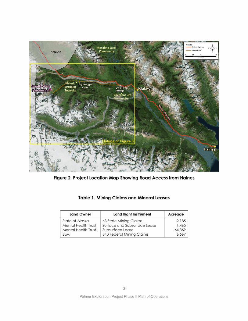
Figure 2. Project Location Map Showing Road Access from Haines .................................... 3
Figure 3. Palmer Project Property Map ...................................................................................... 4
Figure 4. Haines Borough Comprehensive Plan Map .............................................................. 6
Figure 5. Project Layout ............................................................................................................. 16
Figure 6. Proposed Portal Pad Layout ..................................................................................... 17
Figure 7. Settling Pond Design - Plan View .............................................................................. 20
Figure 8. Settling Pond Design - Cross Sections ...................................................................... 21
Figure 9. Design Drawings of Lower Diffuser ........................................................................... 24
Figure 10. Proposed Underground Ramp - Plan View ........................................................... 27
Figure 11. Proposed Underground Ramp - Cross-Section..................................................... 28
Figure 12. Major Components of LAD System ........................................................................ 31
Figure 13. Surface Water Quality Sample Location Map ..................................................... 40
Figure 14. Surface Water Flow Monitoring Stations ................................................................ 44
Figure 15. Groundwater Monitoring Location Map ............................................................... 45
Figure 16. ABA Sample Locations Projected to Section Along Proposed Underground Exploration Ramp (view to northwest) ............................................. 53
Figure 17. Comparison of Modified Neutralizing Potential with Carbonate Neutralizing Potential (pHase, 2018b) ....................................................................... 55
Figure 18. ABA Results for Development Rock Samples (pHase, 2018b) ............................ 56
Figure 19. Comparison of Total Sulfur Versus Sulfide-Sulfur for Development Rock Samples (pHase, 2018b) ............................................................................................. 56
Figure 20. Selenium Concentrates in Humidity Cell Leachate (pHase, 2018d) ................. 57
Figure 21. Reach of Anadromous and Resident Fish in Glacier Creek ............................... 59
Figure 22. Extent of Wetlands Mapping in the Palmer Project Area ................................... 60
LIST OF APPENDICES
MONITORING PLAN ..................................................................................... A
WATER MANAGEMENT PLAN ....................................................................... B
TEMPORARY CLOSURE AND FINAL RECLAMATION PLANS ......................... C
BASELINE ENVIRONMENTAL DATA AND SUMMARY REPORTS .................... D
D.1 Surface Water Quality (Integral 2018) ........................................................................... D
D.2 Surface Water Quantity (Integral 2018) ........................................................................ D
D.3 Groundwater Quality (Integral 2018) ............................................................................. D
D.4 Groundwater Hydrogeology (Tundra 2018) ................................................................. D

D.5 Development Rock Characterization (pHase 2018) ................................................... D
D.6 Wetlands (HDR 2017) ........................................................................................................ D
D.7 Wildlife Report (Hemmera 2015)..................................................................................... D
D.8 Terrestrial Habitat (Hemmera 2016) ............................................................................... D
D.9 Goat Summary Report (Hemmera 2018) ...................................................................... D
D.10 MLARD Monitoring and Management Plan for Exploration Drift Development, Palmer Project (pHase 2018) ................................................................ D
D.11 Hangover and Waterfall Creeks Fish Investigation (ADFG 2018) ............................... D
D.12 LAD Infiltration Tests (BGC 2018) ..................................................................................... D
D.13 Geochemical Source Term Predictions (pHase 2018) ................................................ D
i
Executive Summary
This Plan of Operations (Plan) is submitted to the Mental Health Trust Land Office (Trust), the Alaska Department of Natural Resources (ADNR) and the Alaska Department of Environmental Conservation (ADEC) by Constantine Mining LLC (Constantine or the Company) for the Palmer Advanced Exploration Project (the Project) located in the Porcupine Mining District in Southeast Alaska. This Plan describes the second phase in a two-phase advanced exploration program. Phase I included construction of a surface access road, portal pad, and settling ponds which were partially completed during the 2018 construction season. The two-phase approach was adopted to allow Constantine to initiate the surface access work on Phase I in 2018, while evaluating additional environmental and engineering data to develop final designs and management plans for Phase II.
The activities for which we are seeking approval in this Phase II Plan include:
1. excavating approximately 2,012 meters of underground ramp to provide a drill platform for exploration and provide access to gather additional geotechnical and hydrogeological data,
2. completing approximately 30,000 meters of underground exploration drilling,
3. Placing approximately 70,000 meters3 (170,000 tonnes) of non-PAG development rock on the surface within snow deflection berms and mounds, stockpiles, or use for other construction purposes,
4. Constructing and operating two settling ponds to treat underground seepage water, prior to discharge through the land application disposal system (LAD),
5. Constructing the LAD system to dispose of underground seepage water, The LAD design will be submitted to ADEC for approval separate from this Plan of Operations.
6. Constructing ancillary facilities used in support of the underground exploration program including installation of a generator, air compressor, fuel tanks, explosives storage containers, mine air ventilation fan(s) etc.
The overall exploration program (Phase I and II) is directed at further evaluation of the South Wall Resource that has a resource (indicated +inferred) of 10.01 million tonnes with a grade of 1.21% copper, 5.21% zinc, 0.29 g/t gold and 29.95 g/t silver, using an NSR cut-off of US$75/t. The long-term project objective is to continue the evaluating for as long as warranted by the technical results, and to methodically assess the technical and economic viability of developing an underground mine.
The entire surface disturbance proposed in this Plan will occur on Trust surface lands, where the Trust also owns the subsurface estate. Constantine has an Upland Mining Lease
ii
(No. 9100759) for these lands from the Trust. There are no Federal actions associated with permitting the activities proposed in this Plan so there is no National Environmental Policy Act (NEPA) analysis required for the activities proposed in the Plan.
Constantine is also currently engaged in surface exploration activities, including helicopter-supported core drilling that is already authorized under separate State and Federal authorizations including ADNR APMA #5690 and US Bureau of Land Management (BLM) Decision Record dated 8/18/2016, Case File AA-094088. This Phase II Plan does not incorporate, or discuss further, those surface exploration activities that are already authorized under these ADNR and BLM approvals. Constantine will continue those activities under those existing approvals concurrent with the new activities described in this Phase II Plan.
Thus, this Phase II Plan is to serve the purpose of acquiring approval from the Trust for the surface and subsurface activities described herein and approval from ADNR and ADEC for the Reclamation Plan included in Section 5 and Appendix C of this Plan of Operations. Additional approvals that are required to implement this Phase II Plan include approvals from ADEC for the engineering design of the land application system and disposal of any PAG rock. Those other approvals are being acquired in a process separate from this Plan of Operations and Reclamation Plan approval process.
Constantine has completed a variety of environmental and characterization studies which include Acid Base Accounting, Aquatic Biology, Cultural Resources, Geology, Geotechnical, Water Quality, Groundwater Hydrology, Wetlands, Wildlife and Wildlife Habitat as a major step in characterizing the natural environment in the project area. Information derived from these studies was integrated into this Phase II Plan with the intent of preventing unnecessary or undue environmental degradation to the environment.
This Plan of Operations is supported by several sub plans that address water management, environmental monitoring, and reclamation of the site under temporary and permanent closure scenarios, as well as a significant volume of baseline environmental data. These data and sub plans are included in the appendices.
iii
Abbreviations AAC
ACOE
ADEC
ADOT
ADNR
AHEA
AKNHP
ANSI
APMA
APE
ARD/ML
ASBP
AWAP
BLM
bgs
BMP
BMRR
CAN
cfs
CEM
DMLW
EPA
ESA
HDPE
JDR
km
m
mi
MSGP
MSDS
MSHA
NEPA
NFPA
NLURA
NPDES
OHA
Plan
Project
QAP
ROW
SPCCP
SOA
Alaska Administrative Code
Army Corp. of Engineers
Alaska Department of Environmental Conservation
Alaska Department of Transportation
Alaska Department of Natural Resources
Alaska Hardrock Exploration Application
Alaska National Heritage Program
American National Standards Institute
Application for Permits to Mine in Alaska
Area of Potential Effect
Acid Rock Drainage/Metal Leaching
Alaska Statewide Bonding Pool
Wildlife Action Plan
Bureau of Land Management
below ground surface
Best Management Practice (s)
Bureau of Mining Regulation and Reclamation
Canada
Cubic Feet Per Second
Constantine North, Inc. or Constantine Metal Resources
Division of Mining, Land and Water
Environmental Protection Agency
Endangered Species Act
High Density Polyethylene
Jurisdictional Determination Report
Kilometers
Meters
Miles
Multi-Sector General Permit
Material Safety Data Sheet (s)
Mine Safety and Health Administration
National Environmental Policy Act
National Fire Protection Association
Northern land Use Research Alaska, LLC
National Pollutant Discharge Elimination System
Office of History and Archaeology
Plan of Operations
Palmer Exploration Project
Quality Assurance Plan
Right-of-Way
Spill Prevention Control Countermeasure Plan
State of Alaska

iv
SOI
SSOC
SWPPP
US
SSOC
UUD
Species of Interest
State Species of Conservation Concern
Storm water Pollution Prevention Plan
United States
State Species of Conservation Concern
Unnecessary and Undue Degradation

1
Palmer Exploration Project Phase II Plan of Operations
1.0 INTRODUCTION
This Introduction includes brief descriptions of the project location and access, details about Constantine’s land tenure and state, local and federal management plans that are relevant to the use and management of the lands within the project area.
1.1 Location, Access and Property Description
The Project is in the Porcupine Mining District, 34 mi. northwest of Haines, Alaska, on the eastern margin of the Saint Elias mountain range. The western boundary of the Project is the international border with the Canadian province of British Columbia (Figure 1). The Project is also approximately 17 miles west from the village of Klukwan. Klukwan has approximately 90 residents.
The Project is located proximal to the paved Haines Highway (Alaska Hwy 7), which leads to the town of Haines, Alaska, (Figure 1). Haines (population of 2,400) is a year-round deep-sea port at the northern end of the Alaska Marine Highway System. Haines has been providing services, skilled labor, accommodations and equipment to support Constantine’s exploration activities.
The nearest major economic centers are Juneau (4.5 hours by Ferry) and Whitehorse, Yukon (244 mi. by Haines/Alaska Hwy 7, Canada Hwy 1 and 3). Daily scheduled flights connect Haines with Juneau (< 1 hour), which has daily connections with the continental US.
A secondary gravel logging road connects the project area to the Alaska Hwy 7 via a bridge across the Klehini River at 26 mile. Drill core storage and camp facilities are located on privately-owned land at the Big Nugget Camp located on Porcupine Creek, approximately 7 mi. from the 26-mile bridge (Figure 2).
Surface access to Glacier Creek valley is via a gravel road that extends approximately 4 mi. from the previously mentioned secondary logging road. Constantine upgraded and extended the Glacier Creek access road, under approval from the ADNR, BLM and the Mental Health Trust, in 2014, 2016, 2017 and 2018. At the end of the 2018 construction season the access road extended up to the proposed portal location near the terminus of the Saksaia Glacier. Except for this access road, practical access to most of the property for mineral exploration is by helicopter.
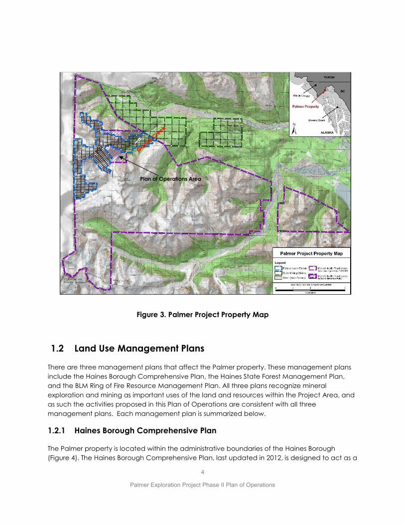
The larger Palmer property consists of a contiguous block of land comprising 340 federal unpatented lode mining claims, which cover an area of approximately 6,567 acres, 63 state mining claims that cover an area of approximately 9,185 acres, as well as approximately 65,834 acres under lease from the Mental Health Trust (Figure 3; Table 1). The surface rights are managed by the BLM, the State of Alaska and the Trust, respectively. However, the entire surface disturbance proposed in this Plan of Operations will occur on Trust lands.

2
Palmer Exploration Project Phase II Plan of Operations
Figure 1. Project Location Map
3
Palmer Exploration Project Phase II Plan of Operations
Figure 2. Project Location Map Showing Road Access from Haines
Table 1. Mining Claims and Mineral Leases
Land Owner Land Right Instrument Acreage
State of Alaska Mental Health Trust Mental Health Trust BLM
63 State Mining Claims Surface and Subsurface Lease Subsurface Lease 340 Federal Mining Claims
9,185 1,465
64,369 6,567
4
Palmer Exploration Project Phase II Plan of Operations
Figure 3. Palmer Project Property Map
1.2 Land Use Management Plans
There are three management plans that affect the Palmer property. These management plans include the Haines Borough Comprehensive Plan, the Haines State Forest Management Plan, and the BLM Ring of Fire Resource Management Plan. All three plans recognize mineral exploration and mining as important uses of the land and resources within the Project Area, and as such the activities proposed in this Plan of Operations are consistent with all three management plans. Each management plan is summarized below.
1.2.1 Haines Borough Comprehensive Plan
The Palmer property is located within the administrative boundaries of the Haines Borough (Figure 4). The Haines Borough Comprehensive Plan, last updated in 2012, is designed to act as a
Plan of Operations Area

5
Palmer Exploration Project Phase II Plan of Operations
guide for citizens and decision-makers for land use, growth and development, and the enhancement of the quality of life for residents and visitors to the Haines community. The Haines region has a history of mining, and mining is noted as an important sector to the local economy, as exemplified by Goal 10 of the Comprehensive Plan which is to “Support responsible development of renewable and nonrenewable resources within Haines Borough.”
The Land Use Designation for the Palmer property in the Comprehensive Plan is Resource Development (Figure 5). The Resource Development designation is for land where “resource development, extraction or harvest activities occur or are reasonably expected, including uses such as timber harvest, mineral extraction and quarries.”
Economic Development Objective 10A of the Comprehensive Plan is to “Work with project developers and regulators to achieve responsible development, which is defined as complying with environmental regulations, ensuring fishery resource and riparian zone protection, providing protection of salmon habitat and Bald Eagle Preserve resources, maintaining scenic view sheds, and buffering operations when needed to protect adjacent users and activities.”
The work proposed in this Plan of Operations is designed to be consistent with the Haines Borough Comprehensive Plan, including the land use designations as Resources Development lands.
1.2.2 Haines State Forest Resource Management Plan
On July 1st, 1982, Alaska took the first step in the development of a system of State-owned lands legislatively dedicated to the multiple use management of forest resources. Alaska Statutes (AS) 41.15.300 established the Haines State Forest Resource Management Area (State Forest). At the same time, AS 41.21.611 established the Alaska Chilkat Bald Eagle Preserve, which is surrounded by the Haines State Forest Resource Management Area. This legislation was the result of cooperation among a host of diverse interest groups including resource developers and wildlife conservationists. AS 41.15.310 instructs the Alaska Division of Forestry to consult the Division of Parks, the Department of Fish and Game and the Alaska Chilkat Bald Eagle Preserve Advisory Council to promote effective, efficient, and coordinated administration of the Haines State Forest Resource Management Area and the Alaska Chilkat Bald Eagle Preserve for the values for which each was established.
The legislature intended the Haines State Forest to include timber harvest, recreation, mining, traditional uses, fish and wildlife habitat protection, tourism, and other uses. The type, intensity, and location of these uses was, under AS 38.04.005, to be derived from a planning process that would determine the best balance of these uses. Most importantly, the State Forest was to be managed for multiple uses. Multiple use management could include a mix of those uses

6
Palmer Exploration Project Phase II Plan of Operations
Figure 4. Haines Borough Comprehensive Plan Map
identified under AS 38.05.112(c) and varying levels of use, depending on the results of the planning analysis.
The Chilkat Bald Eagle Preserve in contrast has an 'exclusive use' management intent, rather than multiple use. Its management focuses on the protection of bald eagles and their habitat, including the spawning and rearing areas of the anadromous streams that provide food for the
Palmer Project Area

7
Palmer Exploration Project Phase II Plan of Operations
bald eagle population. The traditional lifestyle of the Haines community is recognized as an important value and its continuation is included in the management of the Preserve. AS 41.21.60 (c) also includes language that the legislature determines that there is no need for legislation expanding or contracting the boundary of the Alaska Chilkat Bald Eagle Preserve in the future.
This distinction between multiple use and exclusive use was intended by the Legislature. According to AS 41.21.610(c): "Accordingly, the establishment of the Alaska Chilkat Bald Eagle Preserve and the Haines State Forest Resource Management Area under AS 41.15.305 is determined to represent a proper balance between the preservation of state public domain land and water for bald eagle preserve purposes and state public domain land and water more appropriate for multiple use."
1.2.3 BLM - Ring of Fire Management Plan
While the Lands covered by this Plan of Operations are Mental Health Trust lands, the larger property controlled by Constantine also includes some lands managed by the Bureau of Land Management. The BLM approved the Ring of Fire Management Plan through its Record of Decision in March 2008. In 2012, the BLM drafted an amendment to the plan for the Haines area, principally to incorporate considerations for Mountain Goat populations and potential impacts from growing helicopter ski-tourism activities. The draft Haines Area Plan amendment was released for public comment in December 2012, but final approval has been delayed by the BLM. BLM restarted efforts to complete the amendment, including the NEPA process, in March 2018 and that process is ongoing. The mineral potential within the Palmer Project Area was recognized in the 2008 approved Ring of Fire Management Plan which states that the “BLM lands will be managed within the planning process to provide opportunities for mineral exploration and development in a manner that prevents undue and unnecessary degradation resulting from development of locatable and saleable minerals.”
1.2.4 Mental Health Trust Land Use Objectives
The land on which all the Plan activities will occur is leased Mental Health Trust land, where the Trust owns the surface and subsurface estate. There are other portions of the Trust lease lands where the Trust owns the subsurface (mineral) estate and the State owns the surface estate. The Trust originally selected the lands in and around the Palmer Project area primarily for their mineral potential. The Trust’s larger holdings in the area represent approximately 10% of the Trust’s land holdings statewide. Trust lands are managed separately from other State of Alaska lands in accordance with regulations adopted in 1997. The regulations provide that Trust lands are managed solely in the best interest of the Alaska Mental Health Trust Authority and its beneficiaries. Management of Trust land is governed by statute (AS 38.05.801) and regulation (20 AAC 40.010-40.990). The Trust Land Office is required to:
x Protect and enhance the long-term productivity of Trust land;

8
Palmer Exploration Project Phase II Plan of Operations
x Maximize long-term revenue from Trust land;
x Encourage a diversity of revenue-producing uses of Trust land; and
x Manage Trust land prudently, efficiently and with accountability to The Trust and its beneficiaries.
The Trust previously generated a Best Interest Decision as a step in issuing the Upland Mining Lease for the Trust lands that Constantine currently holds. Among other things the Decision determined that “the proposed use is consistent with the designated uses in the (various state and local government land use) Plans. The Decision further states that Trust land was selected for its mineral potential and the only value to the Trust is through mineral exploration, development and production.
The Trust approved the Phase I Plan of Operations for the Palmer Project on April 19, 2018.

9
Palmer Exploration Project Phase II Plan of Operations
2.0 REGULATORY REQUIREMENTS
This section provides a discussion of the regulatory requirements that apply to the activities proposed in this Phase II Plan of Operations. Constantine has designed this Plan to meet these regulatory requirements.
Constantine has made a substantial effort to define the baseline conditions of the natural environment in the project area, in advance of starting any substantial surface disturbance. It has incorporated that baseline data into this Plan and designed its activities with a deliberate objective of minimizing the impacts to the environment that might result from those activities and more than meet all the regulatory requirements addressed in this section.
Constantine has reviewed the applicable State, Federal and local regulations and believes that the activities proposed in the Plan require the following submittals, regulatory reviews and approvals;
• Review and approval of this Phase II Plan of Operations by the Mental Health Land Trust,
• Review and approval of the Reclamation Plan included in Section 5 and Appendix C by ADNR and ADEC.
• Submittal to ADEC of engineered design drawings and other required information as described in 18 AAC 72.600 for the Land Application Disposal (LAD) system for underground seepage water, and receipt of LAD Plan Approval from ADEC under 18 AAC 72.600 and 18 AAC 60.005,
• Apply for temporary water use authorizations from ADNR for the discharge of underground water, use of surface water for underground operations and use of surface water for dust control
• Submittal to ADNR Dam Safety Unit of a completed HAZARD POTENTIAL CLASSIFICATION AND JURISDICTIONAL REVIEW form for the two settling ponds to determine whether the embankments qualify as jurisdictional dams and will be subject to regulation under 11 AAC 93,
• Development of an EPA-compliant Spill Prevention Control and Countermeasure (SPCC) Plan that meets all the requirements of 40 CFR part 112.7.
• Submittal to ADEC of a Notice of Intent (NOI) to operate under Multi-Sector General Permit AKR060000, including a Stormwater Pollution Prevention (SWPP) Plan,
• Submittal to EPA of form 7520-16 under 40 CFR 144.3 to discharge water under a UIC Class V underground injection control permit – for the LAD system. This is an “authorization by rule”

10
Palmer Exploration Project Phase II Plan of Operations
and requires adhering to the requirements of 40 CFR 144.3. But it does not trigger the National Environmental Policy Act (NEPA).
• Registration with ADEC as a Class II Fuel storage facility
The regulatory basis for this list of submittals, reviews and approvals is provided below;
2.1 State of Alaska Regulations
2.1.1 Plan of Operations Regulations
All the lands (surface and subsurface estates) included in this Phase II Plan of Operations are Mental Health Trust lands controlled by Constantine through an upland mining lease with the Trust. One stipulation in the lease is that Constantine provides an annual Plan of Operations for the Trust to review. This Plan will meet the lease requirement as well as serving the needs of ADNR and ADEC for reviewing and approving the Reclamation Plan and associated reclamation cost estimate as allowed under 11 AAC 86.800(f). 11 AAC 86.800(f) states that “For the operator's convenience, a Plan of Operations may include information needed to apply for approvals from other departments or local and federal agencies under other applicable laws and regulations, such as effects of the operation on air and water quality, disposal of toxic wastes, effects on navigation, and effects on anadromous fish habitat”
Constantine’s Phase II Plan of Operation is inclusive of all the activities being proposed so that the document might be useful to other agencies including ADEC and the Mental Health Trust for example.
2.1.2 Dam Safety Regulations
ADNR classifies dams based on the potential hazard of the dam, should there be a failure, according to a scale of I to III under regulation 11 AAC 93.157. Class I dams are considered high risk, class III is low risk.
The two settling ponds include engineered embankments that will impound a volume of water. According to AS 46.17.900 (3) the definition of a dam is a barrier (embankment) that:
A) is > 10 feet high and impounds 50 acre-feet of water or,
B) is > 20 feet high or,
C) poses a threat to lives and property as determined by the department after an inspection;
D) there could be probable loss of or significant damage to waters identified under 11 AAC 195.010(a) as important for the spawning, rearing, or migration of anadromous fish; or
The settling pond embankments do not meet criteria A, B, C or D.

11
Palmer Exploration Project Phase II Plan of Operations
Constantine submitted the designs for the settling ponds to the ADNR Dam Safety Unit for review and they determined that the embankments do not meet the criteria for jurisdictional dams under AS 46.17 and are not subject to regulation as jurisdictional dams under 11 AAC 93.157.
2.1.3 Reclamation Plan and Reclamation Bonding Regulations
Although the lands affected by the activities in the Plan are Trust lands, ADNR retains authority over reclamation and securing a reclamation financial assurance under AS 27.19 and 11 AAC 97. Specifically,11AAC 97.200 sets certain performance standards for reclamation that require a site to be reclaimed to a stable condition relative to erosion (after one year) and to naturally revegetate (after 5 years), as well as other requirements. 11AAC 97.210 addresses the removal of buildings, debris and structures on state land, including the option of leaving buildings and structures if the surface owner or land manager approves it. Additional requirements for the Reclamation Plan are prescribed in 11 AAC97.300. Reclamation bonding is regulated under 11 AAC 97.400 and requires posting a personal bond accompanied by a letter of credit, deposit of gold or cash under 11 AAC 97.410. This Phase II Plan of Operations includes a Reclamation Plan which meets the regulatory requirements for a reclamation plan and it is described in Section 5.0 and in Appendix C with an estimate of reclamation costs. ADEC also has review authority owing to their approval of the LAD design.
2.1.4 Stormwater Regulations
Stormwater on the project site is regulated by ADEC under the APDES Program, delegated to the State by the EPA. Stormwater management for the project is currently managed under the terms of the Construction General Permit (CGP, Permit No. AKR100000) for stormwater discharges associated with Industrial Activity. Stormwater discharges associated with industrial activities are defined by 40 CFR 122.26(b) (14) (i-ix and xi). The CGP authorizes and sets conditions on the discharge of pollutants from certain industrial activities to waters of the United States. To ensure protection of water quality and human health, the permit establishes control measures and best management practices (BMP’s) that must be used to control the types and amounts of pollutants that can be discharged from certain industrial activities. This general permit is intended to regulate stormwater (rain and snowmelt) runoff which encounters industrial activities and materials which have the potential to cause contamination. The quantities and types of stormwater discharged are dependent on many variables, including the type of industrial activity that the facility is engaged in (sector of industry), pollutants of concern, and the type and intensity of the runoff event.
To obtain authorization to operate under the CGP the permittee must develop a SWPPP according to the requirements of permit Part 5 and submit the SWPPP to ADEC. Further, the permittee must select, design, install and implement control measures (BMP’s) to meet effluent limits. Finally, the permittee must submit a complete and accurate Notice of Intent (NOI) to operate under the CGP to ADEC and pay the general permit authorization fee in accordance with 18 AAC 72.

12
Palmer Exploration Project Phase II Plan of Operations
Beginning in 2014 Constantine has maintained a SWPPP and installed BMP’s to meet the pollution minimization requirements of the CGP along the segments of the Glacier Creek access road that it constructed through 2017. Upon the completion of access road and surface facility construction, in 2019, Constantine will file a notice of termination to cease operating under the CGP. Simultaneously Constantine will file a NOI and an updated SWPPP to operate under the Multi Sector General Permit (MSGP, AKG060000) for stormwater. The MSGP/SWPPP will cover stormwater management on the segment of access road on Trust lands where “industrial activities” will continue for as long as Constantine is actively developing the underground ramp.
2.1.5 Non-Domestic Waste Water Regulations
Constantine anticipates groundwater inflows to the development ramp underground, and will manage that water, including discharging the water to the environment through the LAD. The water is classified as nondomestic waste water and subject to regulation by ADEC under 18 AAC 72. Baseline water quality data, discussed elsewhere in this Plan, indicate that the underground seepage water will generally meet Alaska water quality standards with potential exceptions for aluminum and manganese. The water will be subject to passive treatment (for settleable solids) prior to disposal to the LAD diffusers. Constantine is proposing to convey the underground seepage water directly to the upper diffuser, or to two settling ponds prior to disposing the water through the lower diffuser. The diffusers will be buried below the depth of seasonal frost to prevent freezing. This disposal-type does not normally require a permit from ADEC under 18 AAC 72.500, but 18 AAC 72.600 does require that a person who constructs, alters, installs, modifies, or operates any part of a nondomestic wastewater treatment works or disposal system must first have written department approval of engineering plans submitted under 18 AAC 72.500. Nonetheless, Constantine has applied for a Waste Management Permit that will authorize the discharge of non-domestic wastewater as described above.
The LAD also requires registration with the EPA as Class V underground injection well under 40 CFR 144.8, because the design of the LAD includes burying the emitter-end of the system under ground (upper and lower diffusers). This is described in more detail under Section 2.2 below.
2.1.6 Solid Waste Regulations
Development rock (aka “waste” rock) is managed under ADEC solid waste management regulations 18 AAC 60. However, under 18 AAC 60.005 (c) mining waste rock “is exempt from the regulations unless mixed with nonexempt waste, there is a public health, safety, or welfare threat or environmental problem (emphasis added) associated with management of the waste or material, or the waste or material is being managed in a manner that causes or contributes to a nuisance”. ADEC policy is that any mine waste rock that contributes to acid rock drainage or metal leaching into surface or groundwater does pose an “environmental problem” under 18 AAC 60.005 (c). As a result, and as a matter of policy, ADEC requests that mining projects perform acid-base accounting tests on representative samples of waste rock to determine the potential to generate acid or leach metals. Constantine has completed a battery of acid-base
13
Palmer Exploration Project Phase II Plan of Operations
accounting, laboratory and field kinetic tests on samples that are representative of the development rock that will be generated by the excavation of the underground ramp system proposed in this Phase II Plan. The results of that work show that the anticipated development rock will not generate acid or leach metals in the surface weathering environment. As a result, and subject to review by ADEC, Constantine asserts that the development rock will not create an environmental problem and is therefore exempt from any requirements for a permit or other regulation from ADEC under solid waste management regulations18 AAC 60. Notwithstanding, Constantine is proposing to monitor the development rock, as it is brought to the surface, prior to disposal as described in Sections 3.5.2., 4.7 and Appendix A. In addition, Constantine has applied for a Waste Management Permit as a contingency, that authorizes disposal of any PAG rock back underground in the unlikely event that any PAG is encountered.
2.1.7 Fish Passage Regulations
All the activities proposed in the Plan of Operations will occur in the upper portions of the Glacier Creek valley where the creek and its tributaries are non-fish-bearing as verified by ADF&G as recently as 2018. As a result, there are no ADF&G permits required to complete the activities proposed in this Phase II Plan. In addition, ADF&G staff has been performing aquatic studies in Glacier Creek and are familiar with Constantine’s explorations activities to date.
2.1.8 Air Quality Regulations
Constantine proposes utilizing a 600Kw diesel generator at the portal to power all its surface and underground needs (lighting, pumps, fans, drills etc.). An installation such as this is referred to as a “stationary” source under ADEC air regulations. Air quality permits for stationary sources are regulated by ADEC under AS 46.14.130 and 18 AAC 50. There are triggers for the need to obtain air quality permits based on emission levels from the stationary source. Annual emission limits for several air pollutants are prescribed in 18 AAC 50.502. If a stationary source can be operated without exceeding those annual limits, then it may not be necessary to obtain a Minor permit from ADEC. However, per 18 AAC 50.225(a) - The owner or operator of an existing or proposed stationary source may also request an enforceable limit on the ability to emit air pollutants to avoid all permitting obligations under AS 46.14.130. Constantine engaged a consultant to perform and “Air Quality Applicability Determination” for the proposed diesel emission sources contemplated under this Phase II Plan. They concluded that Constantine can continuously operate generators producing up to 1,063 kW (and maintain a standby 1,063 kW generator) and an air compressor up to 125 hp without triggering any requirements for a Minor air permit under AS 46.14.130, as long as the engines meet EPA Tier 4 requirements for emissions and as long as they burn ultra-low sulfur fuel (SLR, 2018). If the generators do not meet Tier 4 requirements but meet Tier 2 or 3 requirements Constantine can still operate up 600kW power generations. Constantine intends to use a Tier4 generator and operate under the 1,063kW permitting threshold.

14
Palmer Exploration Project Phase II Plan of Operations
2.1.9 Fuel Tank Registration Regulations
New ADEC regulations for fuel tank storage went into effect in June 2017. Regulations 18 AAC75.839 to AAC75.849 specify that facilities with fuel tank(s) in excess of 1,000 gallons must register with ADEC as Class II facilities.
Constantine has completed the registration form and is in compliance with these regulations.
2.2 Federal Government Regulations
2.2.1 National Environmental Policy Act
The entire surface disturbance proposed in this Plan of Operations will occur on uplands on Mental Health Trust lands. No dredge or fill of wetlands is being proposed. No Clean Water Act Section 404 wetland permit is required. Underground seepage water and stormwater will be managed under the Alaska Pollution Discharge Elimination and the Federal Drinking Water Act. No decision-level permits are required from the Federal Government to manage water. In the absence of any Federal decision-level permits, NEPA is not required.
2.2.2 Underground Injection Control Regulations
As previously described, the underground seepage water directed to the two settling ponds will be discharged into the ground through an ADEC-approved Land Application Discharge System (LAD). The design of the LAD includes burying the discharge-end of the system (diffuser) underground, below the depth of seasonal frost, to ensure that the system operates year-round. Under this scenario, the LAD meets the definition of a “well” in 40 CFR 144.3 – which defines a well as: A bored, drilled, or driven shaft whose depth is greater than the largest surface dimension; or, a dug hole whose depth is greater than the largest surface dimension; or, an improved sinkhole; or, a subsurface fluid distribution system (emphasis added). Constantine has confirmed with the EPA that the buried diffuser of the LAD is a subsurface fluid distribution system under the definition. As a “well” the LAD will require registration with the EPA as Class V Underground Injection Well, regulated under 40 CFR 144.8.
2.2.3 Fuel Spill Prevention Regulations
Fuel spill prevention is regulated under EPA’s Oil Spills Prevention and Preparedness Regulations under 40 CFR Part 112.
Constantine will be installing fuel tanks near the settling ponds and on the portal pad. Cumulative fuel storage capacity is anticipated to exceed 10,000 gallons which triggers a requirement for a Spill Prevention Control and Countermeasure Plan prepared by a licensed professional engineer in accordance with 40 CFR Part 112.

15
Palmer Exploration Project Phase II Plan of Operations
3.0 DESCRIPTION OF OPERATIONS
This section describes the activities being proposed under this Phase II Plan of Operations. In the Phase I Plan of Operations, approved by the Trust in April 2018, Constantine obtained authorization to construct the access road up to and including the portal pad, the settling ponds and the excavation for the trench for the lower diffuser. In this Phase II Plan of Operations Constantine is proposing new activities including construction of certain support facilities on the portal pad, completion of the LAD, excavation of the underground ramp system and underground exploratory drilling. The layout of the surface and underground facilities (Phase I and Phase II) is illustrated in Figure 5. The major Phase II Plan components include:
x Excavating ~2,012 meters of underground ramp, starting at the portal, and hauling ~70,000 m3 of development rock to the surface,
x Installing the diesel-powered electric generator(s), air compressor, ventilation fan, and fuel storage at the portal pad to support underground activities,
x Operating the two settling ponds to manage underground seepage water,
x Constructing and operating the LAD to discharge underground seepage water,
x Completing approximately 30,000 meters of underground exploration drilling,
x Placing ~70,000 m3 of non-PAG development rock on the surface to construct avalanche deflection structures (berms and mounds) to protect the road and settling ponds or in development rock disposal piles, or using it for road construction and maintenance.
x An updated reclamation plan and cost estimate that incorporates reclamation of all disturbances already approved in the Phase I Plan of Operations and those proposed in this Phase II Plan.
x Offsite activities including a workforce camp and core logging facilities that are not on Trust or State lands and are therefore not discussed in this Plan.
3.1 Surface Operations
3.1.1 Portal Pad Facilities Construction
The portal pad will provide a platform for supporting underground activities. Construction of the pad was approved by the Trust in the Phase I Plan. However, it is now necessary to install certain facilities on the pad in support of the underground program including the diesel-power electric generators(s), air compressor, ventilation fan and fuel storage tanks. The proposed layout for facilities on the portal pad is illustrated in Figure 6.

16
Palmer Exploration Project Phase II Plan of O
perations
Figure 5. Project Layout

17
Palmer Exploration Project Phase II Plan of Operations
Figure 6. Proposed Portal Pad Layout
3.1.2 LAD Construction and Operations
Underground water inflows will be directed to the land application disposal (LAD) system for discharge to the environment. The LAD is a system of piping, ponds and disposal endpoints that accommodate the discharge of underground seepage water, designed by BGC Engineering Inc (BGC, 2018a). The physical components of the LAD system are illustrated in Figure 12 and include the following:
x Two settling ponds. x A buried diffuser consisting of three parallel perforated pipes in separate trenches to
dispose of water treated in the settling ponds (“lower diffuser”). x Piping to convey water from the portal to the settling ponds and from the ponds to the
buried diffuser with pipe valves and manifolds to allow water flow in/around the ponds and through any combination of 6 “zones” in the buried perforated diffuser pipes.

18
Palmer Exploration Project Phase II Plan of Operations
x An upper diffuser to dispose of untreated seepage water early in the underground development program.
x Piping to convey water from the portal to the upper diffuser. x Valves at the portal to control flows to either the upper diffuser or the settling ponds. x Totalizer(s) to record flows to the upper diffuser and settling ponds
3.1.2.1 Settling Pond Construction and Operations
The construction of the settling ponds was approved in the Phase I Plan, but final designs have only recently been completed. As a result, the two settling ponds will be constructed in Spring 2019. These will be lined ponds with a 60 mil HDPE liner. The two settling ponds will allow suspended solids to settle from underground seepage water before that water goes to the lower diffuser. Allowing solids to settle should minimize clogging of the gravel down-gradient of the lower diffuser pipes and extend the useful life of the lower diffuser. Some settling is also anticipated in the underground sumps prior to conveying the water to the LAD system.
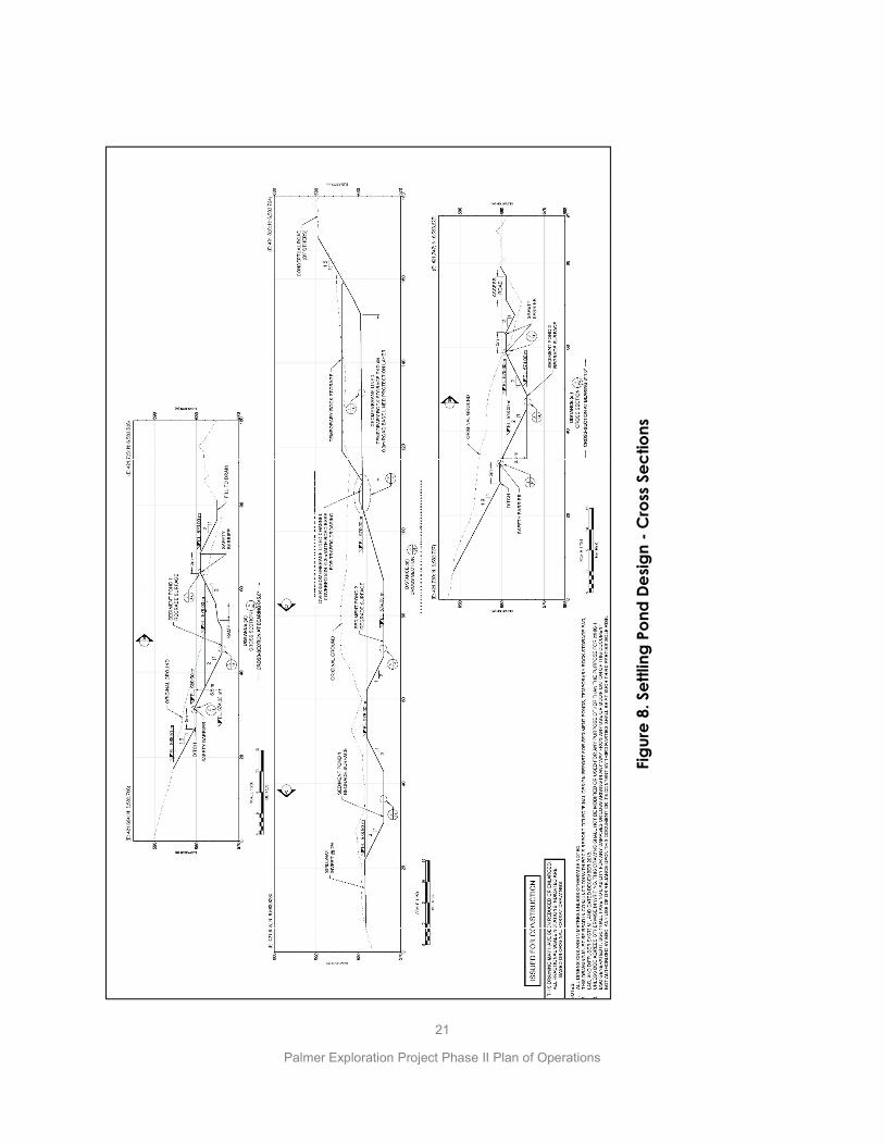
Constantine submitted preliminary designs for two settling ponds in the Phase I Plan of Operations. Constantine has refined the designs into updated design drawings which are included in Figures 7 and 8. These designs were previously submitted to ADNR Dam Safety Unit for a dam jurisdictional review and were deemed NOT to be jurisdictional.
Constantine will be completing construction of the settling ponds, incorporating the updated designs in 2019, and commission the ponds, pending approval of this Phase II Plan by ADNR, and approval of the LAD design by ADEC. The containment capacity for the ponds is based on a retention time of approximately 12 hours for each pond at a maximum flow of 500 gpm, for a corresponding water storage capacity of approximately 1,360 m3 (1.1 acre-feet) in each pond. A freeboard allowance of 1 m (3.3 ft) has been included in the pond designs to account for wave action and storm events. In addition, a separation berm below crest-level divides the two ponds to allow spillage from one another, and a spillway has been included at the northwest end of Settling Pond 1 to accommodate any unanticipated storm event greater than a 100-year, 24-hour storm event.
Typically, water will flow into pond #1 and be allowed to settle before decanting into pond #2 for further settling and then piped down to the lower diffuser. At a rate of 500 gpm, water will have a 12-hour retention time in each of the ponds. A system of pipes and valves provides a degree of flexibility in managing flows to and between the ponds and between the three diffuser pipes. For example, it allows access to one of the ponds for maintenance while the other remains in use. The ponds will be lined with 60 mil HDPE to minimize seepage, reduce the phreatic surface within the embankment and improve overall slope stability.
A practical method (BCME, 2015) for sizing sediment ponds for mine-related applications is presented in the box below that shows that the proposed LAD ponds are of enough size to provide adequate retention time to settle the anticipated solids suspended in the underground seepage

19
Palmer Exploration Project Phase II Plan of Operations
water. The method is acceptable for ponds where the finest suspended particles will be present, thus requiring the maximum retention time. This method utilizes standard assumptions on particle size and settling velocity and is appropriate for projects where no site-specific sediment is available for testing. This design approach has been used to design many sediment ponds at currently operating mines.
Given a minimum pond depth (d) of 1.5 m, defined as the difference in vertical elevation between the inlet water level and the bottom of the ponds adjacent to the outlet, and a settling velocity of 2 x 10⁻⁵ m/s for fine silt, a total retention time of approximately 21 hours is required.
The ponds have been designed for a total retention time of 24 hours (12 hrs./pond, in succession) and have a combined surface area greater than 1,577 m2.
Provision will be made so that approved settling aids can be added if required to enhance settling rates. Additional strategies can also be incorporated into the operation and design to reduce sediment loading into the pond and/or increase the pond’s removal efficiency. As mentioned, outflows may be considerably less than 500 gpm and underground sumps will contribute to total settling time so the overall assessment of the adequacy of the ponds is considered conservative.
At inflows of 250 gpm the settling time will be approximately 24 hours in each pond. The calculations show that settling times of approximately 10.5 hours in each pond (total settling time of 21 hours) are enough to settle the anticipated solids.
Settled water will leave the second pond and flow by gravity to the lower diffuser. The lower diffuser consists of a perforated pipe system buried approximately 10 feet below the surface in permeable alluvial fan gravels. The lower diffuser is being buried to insulate it from the effect of winter frost and allow the system to function in all seasons. The diffuser will be sectioned into 6 zones.
The water conveyance system (pipes) from the portal to the settling ponds can convey up to 3,000 gpm and pipes from the ponds to the lower diffuser are designed to convey at least 800 gpm in the unlikely event that unanticipated inflows are encountered underground. The lower diffuser is also designed to discharge up to 500 gpm indefinitely and up to 800 gpm intermittently. Ultimately operating experience will define the practical discharge limits of the LAD system.

20
Palmer Exploration Project Phase II Plan of Operations
Figu
re 7
. Set
tling
Pon
d De
sign
- Pla
n Vi
ew
21
Palmer Exploration Project Phase II Plan of Operations
Figu
re 8
. Set
tling
Pon
d De
sign
- Cro
ss S
ectio
ns
22
Palmer Exploration Project Phase II Plan of Operations
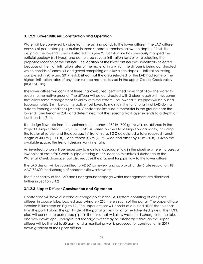
3.1.2.2 Lower Diffuser Construction and Operation
Water will be conveyed by pipe from the settling ponds to the lower diffuser. The LAD diffuser consists of perforated pipes buried in three separate trenches below the depth of frost. The design of the lower diffuser is illustrated in Figure 9. Constantine has previously mapped the surficial geology (soil types) and completed several infiltration tests prior to selecting the proposed location of the diffuser. The location of the lower diffuser was specifically selected because of the high infiltration rates of the material into which the diffuser is being constructed which consists of sands, silt and gravel comprising an alluvial fan deposit. Infiltration testing, completed in 2016 and 2017, established that the area selected for the LAD had some of the highest infiltration rates of any near-surface material tested in the upper Glacier Creek valley (BGC, 2018b).
The lower diffuser will consist of three shallow-buried, perforated pipes that allow the water to seep into the native ground. The diffuser will be constructed with 3 pipes, each with two zones, that allow some management flexibility with the system. The lower diffuser pipes will be buried (approximately 3 m), below the active frost layer, to maintain the functionality of LAD during surface freezing conditions (winter). Constantine installed a thermistor in the ground near the lower diffuser trench in 2017 and determined that the seasonal frost layer extends to a depth of less than 1m (3 ft).
The design flow rate from the sedimentation ponds of 32 l/s (500 gpm) was established in the Project Design Criteria (BGC, July 10, 2018). Based on the LAD design flow capacity, including the factor of safety, and the average infiltration rate, BGC calculated a total required trench length of 400 m (1,300 ft). Each trench is 3 m (9.8 ft) wide and offset by 15 m (50 ft). Given the available space, the trench designs vary in length.
An inverted siphon will be necessary to maintain adequate flow in the pipeline where it crosses a low point at Waterfall Creek. A pipe crossing at this location minimizes disturbance to the Waterfall Creek drainage, but also reduces the gradient for pipe flow to the lower diffuser.
The LAD design will be submitted to ADEC for review and approval, under State regulation 18 AAC 72.600 for discharge of nondomestic wastewater.
The functionality of the LAD and underground seepage water management are discussed further in Section 3.4.2
3.1.2.3 Upper Diffuser Construction and Operation
Constantine will have a second discharge point in the LAD system consisting of an upper diffuser, in coarse talus, located approximately 250 meters south of the portal. The upper diffuser location is illustrated on Figure 12. The upper diffuser will consist of a buried HDPE that extends from the portal along the uphill side of the portal access road to the talus-filled gulley. The HDPE pipe will connect to perforated pipe in the talus that will allow water to discharge into the talus and flow downslope. Underground seepage water may be discharged through the upper diffuser will be limited to 50 gpm, and a monitoring well is proposed for construction in 2019 down-gradient of the upper diffuser.

23
Palmer Exploration Project Phase II Plan of Operations
3.1.3 Development Rock Disposal
Constantine anticipates hauling approximately 170,000 tonnes (70,000 m3) of development rock to the surface while developing ~2,012 meters of underground ramp with nominal dimensions of 5 m x 5 m (16 ft. x 16 ft.). As described elsewhere in Sections 3.5.2 and 4.7 of this Plan the development rock is expected to be non-acid generating (non-PAG) and non-metal-leaching, based on results of a thorough ABA program on rock samples representative of those rock lithologies that will be excavated during the underground program. Constantine proposes permanently disposing of this non-PAG rock by repurposing it for use in constructing the avalanche deflection structures (mounds and berms) shown on Figure 5, and other incidental construction uses such as road maintenance and in piles. Constantine anticipates minimal civil construction to develop the avalanche deflection berm/avalanche mounds. To construct the avalanche berm, the development rock will be end-dumped from the road switchbacks, onto native ground (glaciofluvial material – tills and alluvial gravels). Then, Constantine will shape the pile, using heavy equipment as necessary, to create an elongate berm that will help deflect the edges of snow avalanches away from the access road and settling ponds. Constantine has applied for a waste management permit to dispose of PAG in the unlikely event any is encountered underground.
3.2 UNDERGROUND OPERATIONS
Underground operations will include excavating approximately 2,012 meters (6,601 ft) of underground ramp utilizing a contractor and applying a typical drill-blast-muck cycle to advance the ramp. The ramp is designed to provide a platform from which more detailed exploration drilling can be completed as part of the ongoing evaluation of the South Wall mineralization. The ramp will provide safer, year-round and more practical drilling compared to drilling from the surface where drill pads are constructed on steep slopes, is fully dependent on helicopter support and is only possible during the snow-free months. The underground ramp will also provide continuous bedrock exposures that could allow for detailed geological and geotechnical mapping and generate additional hydrogeological data. All development rock will be hauled to the surface and permanently disposed of/repurposed as described in Section 3.1.4. Development rock management is described in more detail in Section 3.5.2. The underground ramp development will be on both Mental Health Trust and BLM subsurface estate, though no Federal approvals are required because there is no surface disturbance planned for the Federal land in this Plan of Operations. Electric power and compressed air for underground operations will be supplied from facilities staged at the surface on the portal pad as described in Section 3.1.1.

24
Palmer Exploration Project Phase II Plan of Operations
Figu
re 9
. Des
ign
Draw
ings
of L
ower
Diff
user

25
Palmer Exploration Project Phase II Plan of Operations
3.2.1 Underground Ramp Construction
The underground ramp development will include collaring a portal at the portal pad and excavating a cumulative length of approximately 2,012 meters underground. The ramp development will be performed by a contractor. The excavation of the ramp will yield approximately 70,000 m3 of waste rock equivalent to approximately 170,000 tonnes assuming 10% overbreak and 15% swell factor. Starting at the portal, the ramp will consist of the following major segments, with the length and grades as described below and illustrated in Figure 10:
0 meters = Portal Portal – 13m, 13 m-long segment, +2.5% grade 13m – 270m, 257 m-long segment, +2.5% grade 270 – 370 m, 100 m-long segment, +2.5% grade 370 – 1,612 m, 1,242 m-long segment, +12.4% grade 1,612 m, – 2,012 m, 400 m-long segment, +2.5% grade (drill ramp) The cross-sectional dimensions of the ramp would be approximately 5m by 5m (16 ft. by 16 ft.) as illustrated in Figure 11. The last 400 meters of ramp will serve as a platform for drilling. Excavating the ramp will be accomplished with a typical drill-blast-muck cycle, which will operate on a 24-hr basis using two 12-hour shifts. We anticipate the ramp to advance an average of 12 feet per 24-hr day, until the target length is achieved, over an anticipated period of 12 months, although the schedule is subject to modification due to ground conditions, amount of grouting that is done and equipment availability. Cutouts will be excavated periodically on either side of the main ramp to provide room for temporary storage of development rock (muckbays), equipment parking, materials laydowns and water sumps. Two water sumps are tentatively planned. In addition, an underground equipment maintenance bay will be excavated a relatively short distance inside the portal. The preliminary locations of these cutouts are illustrated on Figure 10 but may be modified to avoid poor ground conditions (incompetent rock). Following each blast, the development rock will be hauled to the surface. Generally, it will be placed on the portal pad temporarily before being hauled by truck for use in constructing one of the snow deflection mounds or berms or otherwise repurposed. Some development rock will be disposed of off the side of the portal pad. The following list summarizes the typical equipment that will be used for the underground development work:
x Two 6 yd3 load-haul-dumps (LHD, aka muckers) x One 33-ton underground haul truck x One single- or twin-boom jumbo drill x One bolting machine x One powder truck x Two personnel tractors x Shotcrete equipment x Two fork lifts

26
Palmer Exploration Project Phase II Plan of Operations
Underground ventilation will be provided using electric ventilation fan(s) and a 48-inch (1.07 m) diameter vent tube that will deliver fresh air from the surface to the advancing face, and push stale air out through the portal. The fan will be size-appropriate to consistently deliver enough fresh air. Blasthole drilling will be accomplished using a single- or twin-boom jumbo drill. Blasting will utilize packaged emulsion which has the benefit of minimizing the introduction of nitrate compounds to underground seepage water. Blasting materials (explosives and blasting caps) will be stored and otherwise managed in accordance with MSHA and BATF regulations. Blasting caps will be stored separate from packaged emulsion as illustrated in Figure 5. Development rock will be examined at the surface to confirm its non-PAG character in accordance with Constantine’s development rock segregation plan which is discussed in more detail in Section 4.7. The ramp system is designed to pass through the hanging wall basalt volcanic rocks for most of its length and the limey argillite for a part of it. As a result, Constantine does not expect to intersect any mineralized zones. (i.e. no massive sulfide mineralization), The mineralized zones occur below the hangingwall basalt and argillite units, and there are no plans to remove any mineralized material from the ramp system (i.e. for a bulk sample) under this Phase II Plan of Operations.
3.2.2 UNDERGROUND EXPLORATION DRILLING
Underground exploration will consist of core drilling, utilizing one or more portable electric drills placed at locations along the underground ramp system. The last 400-meter segment of the ramp is specifically designed to provide drill access to the south wall mineralization. The advantage of drilling from underground, compared to the surface, is that it proves safer and more effective drilling because it allows more intersections of the target mineralization in shorter holes and allows Constantine to drill deeper portions of the deposit that are too deep to drill with helicopter-supported drills from the surface. Shorter holes also deviate less and allow better targeting. It is also safer then surface drilling in that it eliminates the need to construct drill platforms on steep slopes and eliminates the intricate slinging operation inherent in helicopter supported drill operations. Underground drilling is also possible on a year-round basis rather than seasonally on the surface. Most drill holes will be down-holes directed at intersecting mineralized horizons below the ramp. Constantine anticipates completing approximately 100,000 ft. of drilling in an approximate total of 150 drillholes. The plan is to grout drillholes with cement to control seepage and for safety, to prevent transferring blast energy between ramp segments in any future underground development. The electric drills will be powered by a diesel genset located on the portal pad. The drills will utilize underground seepage water for drilling purposes, whenever possible. Drilling water will comingle with seepage inflows and all water will report to the mine sump collection system. Drill fluid additives may be required depending on drilling conditions.

27
Palmer Exploration Project Phase II Plan of Operations
Figure 10. Proposed Underground Ramp - Plan View
28
Palmer Exploration Project Phase II Plan of Operations
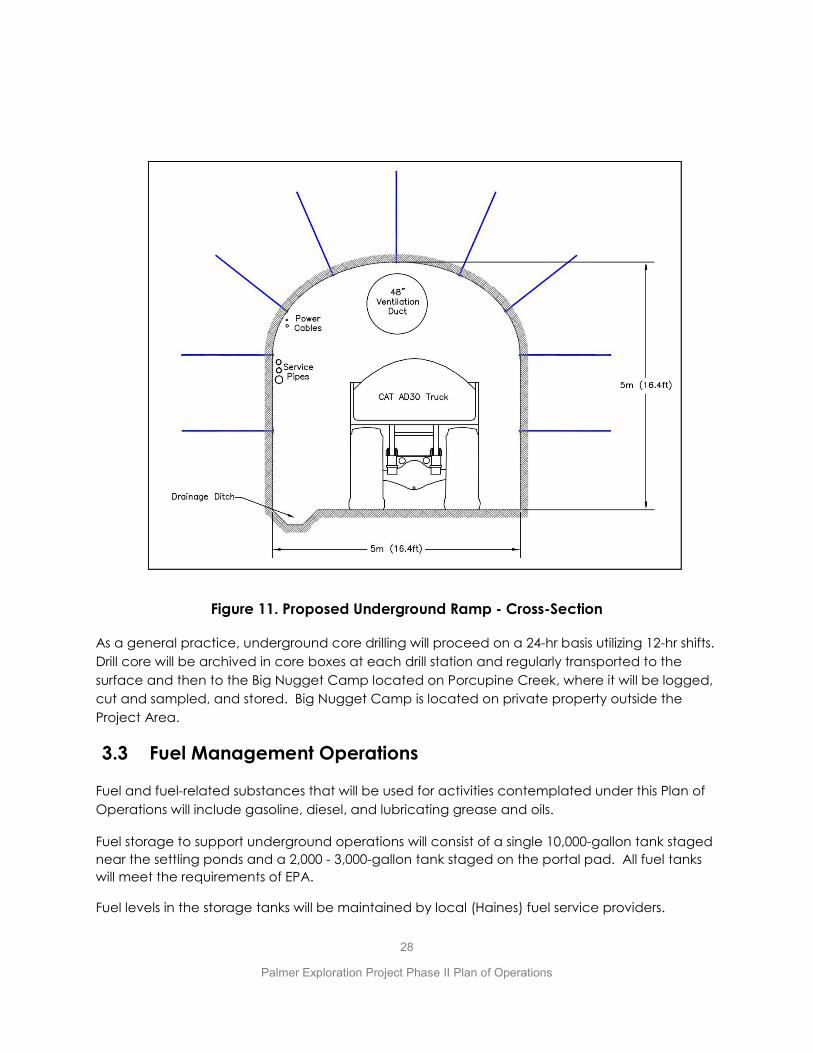
Figure 11. Proposed Underground Ramp - Cross-Section
As a general practice, underground core drilling will proceed on a 24-hr basis utilizing 12-hr shifts. Drill core will be archived in core boxes at each drill station and regularly transported to the surface and then to the Big Nugget Camp located on Porcupine Creek, where it will be logged, cut and sampled, and stored. Big Nugget Camp is located on private property outside the Project Area.
3.3 Fuel Management Operations
Fuel and fuel-related substances that will be used for activities contemplated under this Plan of Operations will include gasoline, diesel, and lubricating grease and oils.
Fuel storage to support underground operations will consist of a single 10,000-gallon tank staged near the settling ponds and a 2,000 - 3,000-gallon tank staged on the portal pad. All fuel tanks will meet the requirements of EPA.
Fuel levels in the storage tanks will be maintained by local (Haines) fuel service providers.

29
Palmer Exploration Project Phase II Plan of Operations
Light-duty vehicles and heavy equipment will also be utilized on the project. Approximately 200 gallons of gasoline will be stored in fuel delivery systems for light vehicles, and approximately 400 gallons of diesel will be stored in fuel delivery systems of heavy equipment.
Constantine personnel are trained in spill prevention and spill response procedures. Spill kits are maintained in key areas. An assigned worker inspects spill kits weekly to check equipment serviceability and ensure that kits are fully stocked. This inspection includes a visual examination of fuel container integrity. Select Constantine personnel complete documented task-training in fuel handling, fuel storage, and fuel transferring procedures at least once a year. All new personnel to the Project must complete the same training before they are authorized to carry-out any fuel-related tasks.
Fuel storage containers are visually checked weekly (or more frequently, as required) by an assigned worker either with a dip-stick or by viewing fuel tank gauges where installed. Fuel levels (and volumes) are also checked in the same manner before storage tanks are re-filled. On a weekly basis, an assigned and qualified worker visually inspects all tanks, couplings, valves, fittings, filter housings, nozzles, and other fittings for signs of deterioration, damage, or leakage. On a weekly basis, or after heavy rainfalls, an assigned worker will also conduct inspections of containments checking for signs of damage, deterioration, discharge, or fuel accumulation. Disposal of hazardous materials is also discussed in Section 3.5.1.
Constantine will have a Fuel Spill Prevention Control and Countermeasure Plan (SPCC) in place prior to the initial filling of any of these tanks.
3.4 Water Management Operations
The project will encounter and manage stormwater on the surface, and groundwater that seeps into the underground ramp which Constantine refers to as “underground seepage water.” Constantine will manage stormwater under terms of Construction General Permit (CGP) AKR100000 until road construction is completed and then switch over to the Multi-Sector General permit (AKR060000). Underground seepage water management does not fall under a specific permit, but that water will be managed and discharged through a buried Land Application Disposal (LAD) system. The design of the LAD must be approved by ADEC under regulations for non-domestic waste water. Water management is discussed in more detail below and in the Water Management Plan in Appendix B.
3.4.1 Stormwater Management
Stormwater is being managed under Construction General Permit (CGP) AKR100000 and in accordance with the Stormwater Pollution Prevention Plan (SWPPP). As outlined in the SWPPP, stormwater is collected along ditches along the portal access road and other disturbed areas and conveyed to discharge points in uplands or to tributaries of Glacier Creek. BMP’s, including energy dissipaters, stilling ponds, relief culverts, and sediment basins are being constructed, where required, to encourage settling of suspended solids from stormwater and reduce the

30
Palmer Exploration Project Phase II Plan of Operations
resulting discharge of pollutants. Stormwater BMP’s will be inspected regularly in accordance with the CGP for function.
Upon completion of all surface construction activities (access road, settling ponds, upper and lower diffusers, portal pad) Constantine will be transitioning over to the Multi-Sector General Permit (AKG060000) for stormwater which is more appropriate for ongoing heavy road traffic on the upper portion of the access road related directly to the underground program. The MSGP will apply to the portion of the Glacier creek access road on Trust lands. A notice of termination for the CGP will be submitted to ADEC after the MSGP permit is in-place. Constantine will continue to maintain the stormwater BMP’s (i.e. ditches) along the remainder of the access road on an as-needed basis for as long as exploration is active, and the road continues to be gated from the public.
3.4.2 Underground Seepage Water Management
Natural groundwater is anticipated to seep into the underground ramp system as the ramp advances. Active water treatment will not be required. This underground seepage water will be collected in the underground sumps, pumped to the portal and directed to the upper diffuser and/or the two settling ponds and discharged through the lower diffuser. Collectively the ponds, piping, upper and lower diffusers are the component parts of the land application system (LAD), illustrated on Figure 13. The LAD design must be approved by ADEC prior to construction. Constantine will be submitting the LAD design to ADEC concomitant with submittal of this Phase II Plan of Operations. Operation of the entire LAD (settling ponds and the upper and lower diffusers) are discussed in Section 3.1.2 and 3.1.3, respectively.
Constantine has been collecting groundwater quality samples from drillholes since 2014 and more specifically from holes along the proposed development ramp alignment since 2017. These data indicate that Constantine will encounter mine inflows in the exploration ramp that will be of sufficient quality to be treated for settleable solids and discharged through the LAD system (pHase 2018a). The predicted water quality of the underground seepage water, accounting for some interaction of the wallrock in the ramp and exposure to blasting residue, is illustrated in Table 2. The groundwater quality data are also described in Section 4.4 and included in Appendix D. In general terms the predicted water quality is only elevated in Al and Mn and marginally V, compared to Alaska Water quality standards. By comparison, background water quality in the two monitoring wells above and below the LAD exceed Alaska water quality standards in Al, Cr, Cu, Fe, and Mn as illustrated in Table 2.

31
Palmer Exploration Project Phase II Plan of Operations
Figure 12. Major Components of LAD System
Tundra Consulting (2018a) used a transient analytical flow model to estimate the volume of natural groundwater inflows (underground seepage water) into the proposed ramp. The method incrementally estimates flow as the ramp is advanced. Sufficient data are available for the first 1,250 m of the ramp (all within Jasper Mountain basalt unit) which would take almost a year to develop. The estimated flow for this portion of the ramp is modeled to peak at approximately 200 gpm and then stabilize at a sustained rate of approximately160 gpm. Short-term higher flow rates could occur from faults and fracture zones. Insufficient data are available to predict inflows for the remaining 760 m of the ramp where it passes through a package of argillite sediments, Kudo fault and the hangingwall basalts. However, based on the limited data, Tundra suggests that a higher flow rate should be anticipated for the remaining 760 m of the ramp. Owing to the uncertainty in the volume of underground seepage inflows, at least in the farthest portions of the proposed ramp, Constantine may drill pilot holes in advance of the ramp, particularly in the argillite and hangingwall basalt units and in the vicinity of the Kudo fault, to identify significant water inflows before intersecting them with the development ramp. Pressure grouting could be used to seal off these water courses prior to tunneling through them. The overall strategy will be to limit total groundwater seepage inflows to the greatest practical
32
Palmer Exploration Project Phase II Plan of Operations
extent, and below 500 gpm for the total ramp. More discussion of Constantine’s water management plan including its adaptive management strategy to water management is included in Appendix B.
Constantine has designed the settling ponds to accommodate flows of 500 gpm, assuming a retention time of 12 hours in each of the two ponds (24 hours total) to allow settling of suspended solids. The lower diffuser and piping are designed to accommodate flows as high as 800 gpm to insure its functionality for the duration of the exploration project. Adding approved settling aids (flocculant) to the ponds, or to underground water sumps to encourage solid settling is an option if the 24-hour settling time in the ponds proves to be insufficient.
Calculations that account for the finest likely particle size (5 micron) suggest that at 500 gpm the water will require approximately 21 hours of retention time to allow solids to settle for a minimum pond area of 1,577 m2. The ponds are sized larger than that and allow 24 hours of retention time at outflows of 500 gpm. In addition, the ponds will provide longer retention times at flows lower than 500 gpm. Constantine expects that for most of the ramp development period, outflows will be approximately 200 gpm, so both the settling ponds and the lower diffuser are conservatively designed, can accommodate the range of uncertainty in flow estimates, and provide a factor of safety for water management.
Underground seepage water quality and quantity will be monitored by opportunistic sampling underground and using a totalizer(s) on the portal water discharge pipes. In addition, Constantine has installed groundwater monitoring wells up-and down-gradient of the lower diffuser site. Constantine has initiated quarterly monitoring of both wells which will continue after water discharge into the groundwater at the lower diffuser is initiated. We anticipate that monitoring of these two wells will become a requirement of the LAD approval from ADEC. Underground seepage water monitoring is discussed in more detail in the Monitoring Plan in Appendix A.
We anticipate that the underground sumps will require periodic removal of the accumulated settled solids (sludge) which will be placed atop waste rock on the surface and visually monitored.

33
Palmer Exploration Project Phase II Plan of Operations
Table 2. Predicted Underground Water Chemistry Compared to Groundwater Chemistry in Monitoring Wells MW-01 and MW-02.
MW-02 (below LAD)
MW-01 (above LAD)
MW-02 (below LAD)
MW-01 (above LAD)
sampled 9/17/2018
sampled 9/17/2018
sampled 9/28/2018
sampled 9/28/2018
Hard as CaCO3 t — — — 255 109 255 255 167 151 151 154pH - — — — 8.8 8.9 8.2 8.9 8.20 8.21 8.18 8.17NH3 as N t 8.4 — t 0.03 n.d. n.d. 0.8 0.0052 0.005 0.005 0.005NO3 as N t 10* — t 0.005 n.d. n.d. 1.1 0.216 0.191 0.414 0.188NO2 as N t 1* — t 0.001 n.d. n.d. 0.08 0.001 0.001 0.001 0.001Al t 0.75 0.75 t 4.51 1.13 6.55 0.043Al d 0.75 0.75 t 0.004 2.9 0.004 2.9 0.0076 0.0103 0.0131 0.0022As t 0.34 0.15 t 0.00044 0.00024 0.00055 0.0001As d 0.34 0.15 d 0.0002 0.003 0.0002 0.003 0.0001 0.0001 0.0001 0.0001Cd t 0.00322 0.00037 t 0.0000709 0.0000573 0.000106 0.000008Cd d 0.00299 0.00033 d 0.00001 0.00016 0.00001 0.00016 0.0000071 0.0000093 0.0000073 0.0000091Cr t 2.5132 0.1201 t Cr-III 0.0102 0.0022 0.0165 0.0004Cr d 0.7942 0.1033 d Cr-III 0.0001 0.008 0.0001 0.008 0.0001 0.00012 0.00027 0.00014Cr t 0.0160 0.0110 d Cr-IV 0.0102 0.0022 0.0165 0.0004Cr d 0.0160 0.0110 d Cr-IV 0.0001 0.008 0.0001 0.008 0.0001 0.00012 0.00027 0.00014Cu t 0.0205 0.0132 t 0.0153 0.00361 0.0218 0.0005Cu d 0.0197 0.0127 d 0.0005 0.008 0.0005 0.008 0.0002 0.0002 0.0002 0.0002Fe t — 1 t 8.59 2.21 12.1 0.077Fe d — 1 t 0.23 0.68 0.23 0.68 0.012 0.018 0.022 0.01Pb t 0.13680 0.00533 t 0.00138 0.000229 0.00183 0.00005Pb d 0.10013 0.00390 d 0.00006 0.0008 0.0001 0.0008 0.00005 0.00005 0.00005 0.00005Mn t 0.05** — t 0.198 0.0428 0.273 0.00154Mn d 0.05** — t 0.08 0.33 0.08 0.33 0.0136 0.00067 0.00482 0.00030Hg t 0.001400 0.000770 d 0.000005 0.000025 0.00005 0.000005Hg d 0.001400 0.000770 d 0.000005 0.00009 0.000005 0.00009 0.000005 0.000005 0.000005 0.000005Ni t 0.6612 0.0735 t 0.00557 0.00242 0.00916 0.0015Ni d 0.6598 0.0733 d 0.0005 0.008 0.001 0.008 0.0005 0.0005 0.0005 0.0005Se t — 0.005 t 0.00163 0.00172 0.00196 0.00184Se d — 0.0046 d 0.00005 0.0028 0.0001 0.0028 0.00162 0.00158 0.00203 0.00199Ag t 0.00760 — t 0.000021 0.00001 0.000028 0.00001Ag d 0.00646 — d 0.00001 0.00016 0.00001 0.00016 0.00001 0.00001 0.00001 0.00001V t 0.1*** — t 0.0234 0.00600 0.0325 0.0005V d 0.1*** — t 0.0005 0.11 0.0005 0.11 0.0005 0.0005 0.0005 0.0005Zn t 0.1689 0.1689 t 0.0275 0.0063 0.0376 0.003Zn d 0.1652 0.1666 d 0.0006 0.05 0.0006 0.05 0.001 0.001 0.0018 0.001
Notes:
chronic exceedance
acute exceedance
Detection limit presented for values under detection limit; groundwater data has not undergone full QA/QC processGuidelines were taken from: Alaska Water Quality Criteria Manual for Toxic And Other Deleterious Organic and Inorganic Substances (DEC, 2008) ; guidelines for total recoverable and dissolved metals are presentedAcute and Chronic guidelines for Freshwater Aquatic Life are presented, unless more stringent guidelines were available; * = drinking water; ** = human health for the consumption of water and aquatic organisms; *** = irrigation water If parameters of interest are not presented, no exceedance was observedFor calculation of hardness-dependent guidelines, an assumed hardness of 150 mg/L as CaCO3 was used; pH was assumed to be≥8
Note modelled data is presented as dissolved metals and groundwater data is presented as both the total recoverable fraction and dissolved metals (mg/L)
Parameter as
Alaska Guidelines Discharge Wastewater Chemistry (Predicted) Groundwater Chemistry from Monitoring Wells (actual)
ACUTE Guideline
(mg/L)
CHRONIC Guideline
(mg/L) as
Background Groundwater
(GW) at Station P29
GW + Scaled Humidity Cell Concentratio
n
GW + Field Barrel
Concentration
Conservative Predicted Discharge
Wastewater Chemistry
34
Palmer Exploration Project Phase II Plan of Operations
3.4.3 Water Use
Water will be used for excavating the development ramp and for underground exploration core drilling. For surface uses (dust control, portal pad/collar and initial ramp development) water will be sourced from sites already approved under one of a three Alaska Temporary Water Use Authorizations (TWUA). Constantine currently has authorization for 15 designated water source locations under three temporary water use authorizations - TWUA F2014-101, F2014-102 and F2015-080 to support potential drilling activities at various locations across the property. TWUA F2014-101 expired on October 31, 2018. Constantine has applied for two new TWUA to support 2019 operations. Constantine still needs to apply for another TWUA to support underground operations.
TWUA F2014-102 expires on Dec 31, 2018, 2018; F2015-080 expires on July 13, 2020. The TWUA’s contain 27 conditions that must be complied with, including conditions designed to protect water quality and aquatic resources. For example, in fish-bearing waters, intake screens must be designed to avoid fish entrapment, entrainment or injury (note that none of the currently authorized sources are known to be fish-bearing) and pumping operations must be conducted in a way to prevent petroleum products or hazardous substances entering the surface or groundwater. Authorizations F2014-101 and F2014-102 each allowed for the combined withdraw of up 86,400 gallons of water per day between May 1st and October 31st at an intake rate of up to 20 gallons per minute per pump, subject to a maximum of three pumps per source. Primarily TWUA’s will be used to support any surface exploration drilling activities which are authorized under Constantine’s multi-year APMA # J145690 permit and are not discussed further in this Plan of Operations.
Beyond the portal pad excavation and initial ramp development, the underground development and drilling activities will rely on underground seepage water inflows or underground drillholes for its water uses for the remainder of the project. Constantine will apply for any required TWUA’s as soon as practical after identifying a suitable water source underground. Constantine will also apply for a TWUA to authorize the discharge of the underground water through the LAD system.
Water used for underground drilling will generally be combined with industry-standard drill additives (drill mud). Drill muds are used to help remove drill cuttings and maintain fluid circulation and are generally required to advance deep drill holes in fractured rock. NSF/ANSI 60 certified products, i.e. those approved for use in drilling human drinking water wells, are utilized on a preferred basis.
There are no current plans to use any site water for domestic uses during the activities proposed in this Plan of Operations.
3.5 Waste Management Operations
Constantine will generate certain waste streams in the normal course of completing the operations proposed in this Plan of Operations.
35
Palmer Exploration Project Phase II Plan of Operations
Waste streams include approximately 70,000 m3 of non-PAG development rock that will be extracted as the development ramp advances, sludge that will derive from drilling and blasting operations and accumulate in underground seepage water sumps, used motor oils and lubricants from maintenance of mobile underground equipment, and other incidental solid waste including cardboard, wood scrap, steel, etc.
As described below, development rock and sludge will be managed on site while all other wastes will be routinely removed from site. We anticipate that most waste removed from site will be disposed of in the Haines landfill or be recycled. Hazardous waste may go to Whitehorse, Yukon where they are better able to handle it. Waste management of these substances is discussed in more detail below.
3.5.1 Hazardous Waste
Alaska Statute AS 46.03.826 defines a “hazardous substance" as (A) an element or compound which, when it enters into the atmosphere or in or upon the water or surface or subsurface land of the state, presents an imminent and substantial danger to the public health or welfare, including but not limited to fish, animals, vegetation, or any part of the natural habitat in which they are found; (B) oil; or (C) a substance defined as a hazardous substance under 42 U.S.C. 9601(14); These wastes are regulated under several ADEC programs. Constantine will generate hazardous waste in the form of used waste oil derived from maintenance of the mobile fleet of equipment used on site. All hazardous wastes generated by the Project will be disposed of at an authorized facility off site, consistent with applicable regulations.
All containers of hazardous substances, including used waste oil, will be labeled and transported in accordance with Alaska Department of Transportation (ADOT) regulations.
If a reportable quantity of hazardous material including fuel or a hazardous waste is spilled, measures will be taken to control the spill and the ADEC Emergency Response Hotline will be notified, as required. If any oil, hazardous material, or chemicals are spilled during operations, they will be cleaned up in a timely manner. After clean-up, the hazardous waste and any contaminated material will be removed and disposed of at an approved disposal facility.
Fueling management operations are also described in Section 3.3
3.5.2 Development Rock Management
Constantine anticipates bringing approximately 170,000 tonnes (70,000 m3) of development rock to the surface to excavate ~2,012 meters of underground ramp. As described in Section 4.7 the development rock is expected to be non-acid generating (non-PAG) and non-metal-leaching based on a results of a thorough Acid Base Accounting (ABA) program on rock samples representative of those rock lithologies that will be excavated during the underground program. As a result, this material does not pose an environmental risk, making it exempt from regulation or permitting under Alaska solid waste regulations (18 AAC 60.005). Nonetheless Constantine

36
Palmer Exploration Project Phase II Plan of Operations
will monitor development rock as it is brought to the surface so that in the unlikely event that any blast round suspected of being potentially acid generating (PAG) is identified, it will be segregated, sampled and stored on the lined rock storage pad adjacent to the settling ponds, pending the results of geochemical analysis. The monitoring will include a visual examination of development rock based on mineralogical criteria developed during the ABA test program.
If the average sulfide content of any round exceeds 2 % it will be placed on the lined rock stockpile and sampled for ABA analyses. Final disposition will depend on the ABA analyses. PAG material will eventually be placed underground and non-PAG material may be repurposed on the surface. In addition, Constantine plans to perform ongoing development rock sampling to confirm the non-PAG character and this monitoring is discussed in more detail in Section 4.7 and in the Monitoring Plan in Appendix A.
Permanent disposal of confirmed PAG development rock is discussed in the Reclamation Plan in Section 5. Under a permanent closure scenario PAG rock will be placed back underground. Haulage costs to move 4 rounds of PAG rock (~1,000 tons) are included in the reclamation cost estimate in Section 5 and Appendix C. This permanent disposal would also be authorized under the anticipated Waste Management Permit.
Constantine proposes permanently disposing of this non-PAG rock by repurposing most of it to construct the avalanche deflection berm and avalanche mounds shown on Figure 5. As mentioned above, the geochemical character of the development rock has been established through a series of acid-base-accounting analyses and kinetic tests and is expected to be non-acid generating (non-PAG) and non-metal leaching (i.e. benign) under surface-weathering conditions. As a result, there are no plans to cover or otherwise modify the avalanche deflection berm/avalanche mounds or any other non-PAG development rock at closure or at any time in the future. The geochemical characterization of the development rock is discussed in more detail in Section 4.7.
3.6 Snow Management – Operational Avalanche Safety
The Glacier Creek Valley is subject to snow avalanches throughout the winter and spring months owing to high snowfall amounts and the steep terrain. Constantine initiated a snow monitoring program that collects snow depth and avalanche data using both instrumentation and aerial-based observations. The results of that monitoring program suggest that the Glacier Creek access road to the portal site is subject to periodic avalanches that could restrict access both during periods of high avalanche risk and during snow clearing operations after avalanches. Both the portal area and the settling ponds have been designed to avoid the main paths of dense avalanches, but they are at some risk of being impacted by powder avalanches and or the lateral portions of dense avalanches. Constantine has engaged avalanche consultants to evaluate the snow and avalanche monitoring data and are developing strategies to protect public safety during the avalanche season. As discussed elsewhere Constantine will construct snow deflection structures along the access road and will likely implement some form of active

37
Palmer Exploration Project Phase II Plan of Operations
avalanche management including mechanically triggering controlled avalanches as step toward reducing the incidence of larger, potentially destructive avalanches.

38
Palmer Exploration Project Phase II Plan of Operations
4.0 ENVIRONMENTAL CHARACTERIZATION AND MONITORING
Constantine has been performing several environmental characterization and mapping programs for the project, starting as early as 2008. Most of these efforts started in 2014, some are ongoing, and some monitoring will continue for the foreseeable future as describer further in this section and in the Monitoring Plan in Appendix A. The broader effort has included surface water and groundwater quality and hydrology characterization, aquatic life surveys, wildlife surveys, terrestrial ecosystem and vegetation surveys, wetlands surveys, cultural resources surveys, meteorological monitoring, snow surveys and monitoring, and development rock characterization studies.
The data from these efforts contribute to a fundamental understanding of the natural environment in the project area, including a baseline of environmental conditions. They define an environmental backdrop that Constantine can design around, and one against which Constantine can detect potential changes, over time.
The various surveys, monitoring and characterization efforts are each discussed in this section. Those that will continue through the underground exploration program proposed in this Plan of Operations are so-noted in this section and also described in the Monitoring Plan in Appendix A. Baseline data and summary reports by subject experts are provided in Appendix D.
4.1 Meteorological Monitoring
Constantine has engaged consultants Tetra Tech and Ramboll (current) to analyze meteorological data from two stations in the project area. Precipitation, temperature, solar radiation, wind speed and direction, relative humidity and snow depth data are collected at one station along the existing Glacier Creek access road, and temperature, wind speed and direction data (primarily to assist with avalanche forecasting) are collected from a second station, located on the ridge north of Glacier Creek (South Wall). The station on the access road has been operational since 2014 and the other since 2016. The data are collected in accordance with a QAPP for each station. Monitoring will continue at both stations for the foreseeable future.
4.2 Snow Surveys and Monitoring
Constantine has engaged several consultants to monitor and characterize the snow conditions that exist seasonally at Palmer. Of primary concern for the project is the risk of snow avalanches, which are a common phenomenon in the Glacier Creek Valley. Constantine anticipated that it will have to incorporate active snow management into their activities to protect the safety of project personnel and equipment.

39
Palmer Exploration Project Phase II Plan of Operations
Beginning in 2015 Constantine has been integrating snow survey and measurement data to characterize the snow conditions in the Glacier Creek Valley, with the goal of developing an operational avalanche safety plan that will enable them to implement their proposed program safely.
Constantine has monitored snow depth and snowpack temperature profiles at two stations on the South Wall at an elevation of 875m and 1260m since 2015. The sites were selected to provide snow information specific to a potential portal site that has since been deleted from the list of potential portal sites. In addition to monitoring snow depth and temperature, an avalanche and snow observation program within the Glacier Creek Valley was designed to gather baseline information about avalanches, weather and snowpack. This information is being used to guide the design and planning of certain elements of the plan of operations, such as road design, snow deflection berms and mounds, portal and other facility placement and identifying mitigation options for the avalanche impacts.
Constantine has prepared annual reports for the snow depth and temperature monitoring for 2015, 2016 and 2017. These reports are available on request.
4.3 Surface Water Quality and Flow Monitoring
Glacier Creek and its tributaries provide the primary drainage within the Palmer project boundary, ultimately flowing into the Klehini River. Constantine has performed water quality and quantity (hydrology) surveys on surface water within the Glacier Creek watershed and surrounding areas.
Constantine has been performing surface water quality sampling since 2008 from as many as 27 stations, and surface water flow measurements from 13 stations since 2014.
Constantine intends to continue some surface water quality and flow sampling as described in more detail below and in the Monitoring Plan in Appendix A.
4.3.1 Surface Water Quality Characterization
Constantine has been characterizing surface water quality by collecting samples from up to 27 stations since 2008. Those stations are illustrated in Figure13 and include stations along the Klehini River, Glacier Creek and tributaries of Glacier Creek. Constantine’s consultant, Integral Consulting, has prepared a summary water quality memorandum for the period 2008 – 2017, which is included in Appendix D (Integral, 2018a). Detailed sample collection, handling, and analysis information is presented in the Palmer project QAPP in Appendix A (Integral, 2018b).
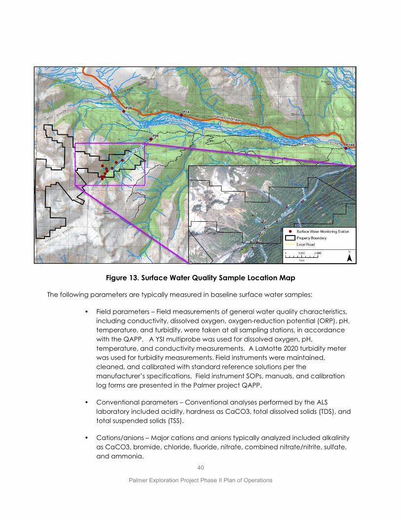
40
Palmer Exploration Project Phase II Plan of Operations
Figure 13. Surface Water Quality Sample Location Map
The following parameters are typically measured in baseline surface water samples:
• Field parameters – Field measurements of general water quality characteristics, including conductivity, dissolved oxygen, oxygen-reduction potential (ORP), pH, temperature, and turbidity, were taken at all sampling stations, in accordance with the QAPP. A YSI multiprobe was used for dissolved oxygen, pH, temperature, and conductivity measurements. A LaMotte 2020 turbidity meter was used for turbidity measurements. Field instruments were maintained, cleaned, and calibrated with standard reference solutions per the manufacturer’s specifications. Field instrument SOPs, manuals, and calibration log forms are presented in the Palmer project QAPP.
• Conventional parameters – Conventional analyses performed by the ALS laboratory included acidity, hardness as CaCO3, total dissolved solids (TDS), and total suspended solids (TSS).
• Cations/anions – Major cations and anions typically analyzed included alkalinity as CaCO3, bromide, chloride, fluoride, nitrate, combined nitrate/nitrite, sulfate, and ammonia.

41
Palmer Exploration Project Phase II Plan of Operations
• Total/Dissolved Metals – Thirty-three metals were analyzed for both the total and dissolved fraction.
Integral (2018a) observed a large variability in the concentrations of many water quality parameters between locations and at different times of year. Differences in local geology and mineralization, as well as the variable proportion of glacial melt/surface runoff and base flow comprising streamflow, are expected to influence water quality and drive variations in conventional, major ion, and metal concentrations between sampling locations. Larger, glacier fed streams (the Klehini River and Glacier Creek) tend to carry higher amounts of suspended solids during periods of snowmelt (late spring through summer) and during precipitation events. Smaller tributaries generally have lower suspended solid loads, clearer waters, and lower flow volume; water chemistry in these stream may be more heavily influenced by groundwater and local geology.
As summarized by Integral (2018a), the surface waters in the project area generally exhibit high quality water. However, some natural surface water concentrations measured were above the chronic and acute water quality standards for the following metals (as summarized in Table 3):
• Chronic and acute standards widely exceeded for total aluminum (Klehini River, Glacier Creek, Waterfall Creek, Hangover Creek, Oxide Creek, Argillite Creek)
• Chronic standard for dissolved cadmium exceeded at sites in Oxide Creek
• Chronic standard for total Iron extensively exceeded (Klehini River, Glacier Creek, Waterfall Creek, Hangover Creek, Oxide Creek, Argillite Creek)
• Total selenium above chronic life standard in Argillite Creek
• Dissolved zinc exceeded acute standards in lower Oxide Creek
• Concentrations of total manganese were above the human health consumption (water + organisms) standard at multiple stations (Klehini River, Glacier Creek, Waterfall Creek, Hangover Creek, Oxide Creek, Argillite Creek)
• Note that elevated aluminum, iron and manganese concentrations were associated with particulates suspended in the water (TSS) (Integral, 2018a)
For all metals except cadmium, the laboratory reports and/or validator-assigned concentration detection limits are below the Alaska water quality standards. This indicates that the analytical methods used meet the DQO outlined in the project QAPP are appropriate, and that the baseline data set is acceptable for comparison to Alaska water quality guidelines.
Now that Constantine has characterized the baseline water quality in the broader Palmer project area, the company now plans to reduce the total number of surface water quality sample sites. Reductions in the scope of environmental baseline monitoring are common for advanced exploration projects following collection of sufficient data to characterize an area somewhat larger than the anticipated footprint of the project. Constantine will continue monitoring at sites P01 and P27 in upper and mid-Glacier Creek, respectively in addition to sites

42
Palmer Exploration Project Phase II Plan of Operations
in Waterfall Creek (P25) and Waterfall Creek (P26). These sites are the most relevant sites for detecting any significant change in water quality, over time, that may be concomitant with Constantine’s underground exploration activities which are restricted to the upper Glacier Creek area. Surface water quality monitoring is also discussed in the Monitoring Plan in Appendix A.
Table 3. Comparison of Surface Water Quality to Freshwater Aquatic Life and Human
Health Criteria for Metals
4.3.2 SURFACE WATER FLOW MONITORING
Constantine has been recording surface water flows (aka hydrology) at 11 sites in Glacier Creek since 2014. These survey sites and two USGS stream gauge sites are illustrated on Figure 14.
Glacier Creek ranges from 4 cfs to 470 cfs, depending on location and time of year, with peak flows occurring during freshet (snow melt) in late spring and summer (Integral, 2018c). The Klehini River runs from west to east along the northern property boundary, flowing approximately 40 miles from its glacial headwaters in British Columbia to the confluence with the Chilkat River, approximately 25 miles south of the Palmer project area. Flow in this large, braided river varies seasonally; average monthly flows measured above the confluence with the Chilkat River from

43
Palmer Exploration Project Phase II Plan of Operations
1983 to 1991 ranged from 220 cfs in winter months (January through March) to over 4,100 cfs in the summer (June through August).
Based on the relative size of the Klehini River and Glacier Creek drainage areas, typical flows in Glacier Creek during the summer months may be estimated as 5 percent of the Klehini River flows, yielding approximately 150 cfs. The Klehini River winter discharge is approximately 90 percent greater than the Glacier Creek downstream flow of 31 cfs measured in January 2018, which is consistent with the relative drainage basin areas.
Based on available data for Glacier Creek:
x The largest surface water flow contributions to Glacier Creek appear to be from the Waterfall Creek, Christmas Creek, and Hangover Creek catchments,
x Surface water flows entering Glacier Creek from the eastside tributaries are up to 12 times greater than flows entering from the westside tributaries.
x Glacier Creek flow approximately doubles from the upstream station (P1) to downstream station (P6), over a distance of approximately 4 miles.
Surface water in the region exhibits seasonal patterns due to the influences of snowmelt, rainfall events, and ambient air temperature. Upon examination of the streamflow hydrograph, two seasonal patterns emerge. The first pattern illustrates the dominant character of the Klehini River watershed, whereby snowmelt runoff drives annual peak stream discharge in the spring. The onset of peak flow (the rising limb) occurs quickly in the late spring to early summer months, generally late April through June. Peak flows occur when average daily air temperatures routinely exceed freezing and when total monthly rainfall is lowest, indicating that snowmelt drives the hydrographic peak. During the period following peak flow (the falling limb), beginning in the late summer months until early fall, stream discharge gradually declines as the snow pack recedes and average daily air temperatures approach freezing. Klehini River discharge remains near base flow throughout the winter and early spring months, typically from November to April. During this time, individual precipitation events produce short-lived increases in stream discharge above base flow. A second pattern can be seen in the Klehini River hydrograph for most years, when river discharge shows a secondary peak in late fall. The late fall peak discharge events occur when total monthly precipitation begins to increase and before average daily temperatures dip below freezing. The increase, and subsequent decline in late fall discharge, occur over a much shorter period than the summertime peak discharge cycle because individual precipitation events, rather than snowmelt runoff, provide runoff for the late fall peak flow. Stream discharge measurements taken at Glacier Creek stations show seasonal patterns like the Klehini River hydrograph (Integral, 2018c).

44
Palmer Exploration Project Phase II Plan of Operations
Figure 14. Surface Water Flow Monitoring Stations
Going forward Constantine will continue to monitor stream flows at sites P01, P27, P25 and P26 which are also site for monitoring water quality in Glacier Creek, Waterfall Creek and Hangover Creek as discussed in the Monitoring Plan in Appendix A.
4.4 Groundwater Quality Monitoring
Constantine has been performing groundwater quality monitoring (sampling) since 2014. A primary objective of the sampling is to characterize groundwater as a step in predicting the quality of seepage water inflows into any future underground ramp, including the underground ramp being proposed in this Phase II Plan of Operations. The secondary objective is to characterize the background groundwater in the area of the proposed LAD. Constantine’s consultant, Integral Consulting, has developed a QAPP to guide the groundwater sampling efforts (Integral, 2018b). That QAPP is provided in Appendix A.
Constantine are monitoring groundwater at three sites including P17, P19 and P29 as shown on Figure 15. These sites provide information on potential seeps to the underground. P17 is a drillhole (GT14-01, U6) with artesian flow, as is P29 (GT17-05, Hari). P19 is an intermittent spring at the base of an area referred to as Paddy’s Pocket. A groundwater quality report for 2014 – 2018 data has been prepared by Integral (2018d) and is included in Appendix D.
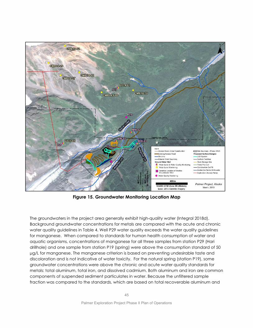
45
Palmer Exploration Project Phase II Plan of Operations
Figure 15. Groundwater Monitoring Location Map
The groundwaters in the project area generally exhibit high-quality water (Integral 2018d). Background groundwater concentrations for metals are compared with the acute and chronic water quality guidelines in Table 4. Well P29 water quality exceeds the water quality guidelines for manganese. When compared to standards for human health consumption of water and aquatic organisms, concentrations of manganese for all three samples from station P29 (Hari drillhole) and one sample from station P19 (spring) were above the consumption standard of 50 μg/L for manganese. The manganese criterion is based on preventing undesirable taste and discoloration and is not indicative of water toxicity. For the natural spring (station P19), some groundwater concentrations were above the chronic and acute water quality standards for metals: total aluminum, total iron, and dissolved cadmium. Both aluminum and iron are common components of suspended sediment particulates in water. Because the unfiltered sample fraction was compared to the standards, which are based on total recoverable aluminum and

46
Palmer Exploration Project Phase II Plan of Operations
total recoverable iron, the sample concentrations are influenced by aluminum and iron associated with particulates suspended in the water.
In 2018 Constantine developed three monitoring wells to characterize shallow groundwater below the proposed settling ponds (MW-03) and the proposed lower diffuser site (MW-01 up-gradient and MW-02 down-gradient). Water quality for wells proximal to the lower diffuser is presented in Table 2. Constantine plans of developing a fourth groundwater monitoring well down-gradient of the upper diffuser.
Constantine intends to continue groundwater sampling, including sampling select underground seepage water inflows as described in more detail in the Monitoring Plan in Appendix A.
4.5 HYDROGEOLOGY TESTS, GROUNDWATER LEVEL MONITORING AND GROUNDWATER MODELING
Constantine has performed several hydrogeology tests and computer modeling to estimate the seepage water inflow rates into the proposed ramp as discussed below. In addition, it has been monitoring seasonal fluctuations in the groundwater levels (water table) in several holes.
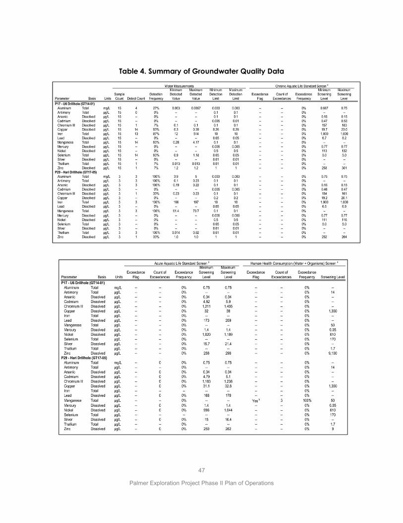
47
Palmer Exploration Project Phase II Plan of Operations
Table 4. Summary of Groundwater Quality Data

48
Palmer Exploration Project Phase II Plan of Operations
4.5.1 HYDROGEOLOGY TESTS
Beginning in 2016, Constantine performed a series of hydrogeology tests in drill holes including isolated interval tests (packer tests) and flow/shut-in tests.
Based on the results of the 2016 program Tundra concluded that groundwater flow is largely vertical, as a function of the steep character of bedrock faulting. Groundwater flow along the faults varies seasonally. The work also suggested that the reservoir capacity of the faults is low and that after an initial inflow of underground seepage water from these structures, they should drain down relatively quickly, and base flow rates may be relatively low.
In 2017 the hydrogeology program re-focused on the ramp alignment proposed in this Phase II Plan of Operations and included 19 packer tests and one 52-day flow/shut-in test. The program is
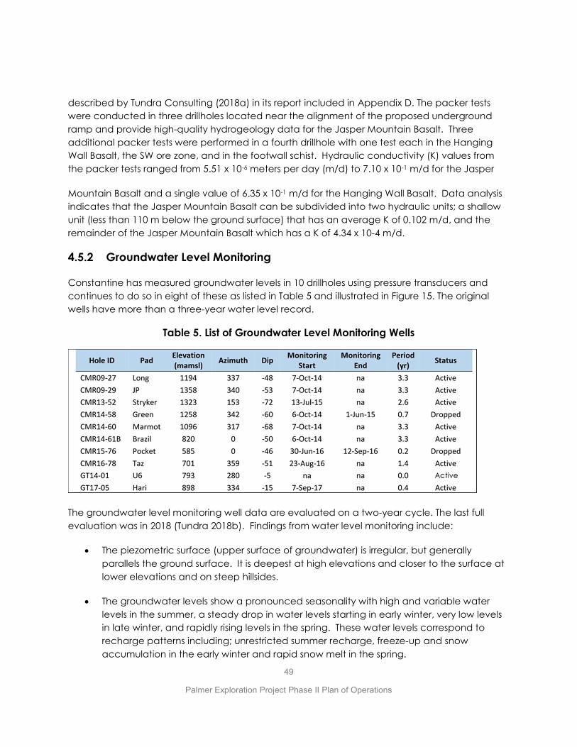
49
Palmer Exploration Project Phase II Plan of Operations
described by Tundra Consulting (2018a) in its report included in Appendix D. The packer tests were conducted in three drillholes located near the alignment of the proposed underground ramp and provide high-quality hydrogeology data for the Jasper Mountain Basalt. Three additional packer tests were performed in a fourth drillhole with one test each in the Hanging Wall Basalt, the SW ore zone, and in the footwall schist. Hydraulic conductivity (K) values from the packer tests ranged from 5.51 x 10⁻⁶ meters per day (m/d) to 7.10 x 10⁻¹ m/d for the Jasper
Mountain Basalt and a single value of 6.35 x 10⁻¹ m/d for the Hanging Wall Basalt. Data analysis indicates that the Jasper Mountain Basalt can be subdivided into two hydraulic units; a shallow unit (less than 110 m below the ground surface) that has an average K of 0.102 m/d, and the remainder of the Jasper Mountain Basalt which has a K of 4.34 x 10⁻⁴ m/d.
4.5.2 Groundwater Level Monitoring
Constantine has measured groundwater levels in 10 drillholes using pressure transducers and continues to do so in eight of these as listed in Table 5 and illustrated in Figure 15. The original wells have more than a three-year water level record.
Table 5. List of Groundwater Level Monitoring Wells
The groundwater level monitoring well data are evaluated on a two-year cycle. The last full evaluation was in 2018 (Tundra 2018b). Findings from water level monitoring include:
x The piezometric surface (upper surface of groundwater) is irregular, but generally parallels the ground surface. It is deepest at high elevations and closer to the surface at lower elevations and on steep hillsides.
x The groundwater levels show a pronounced seasonality with high and variable water levels in the summer, a steady drop in water levels starting in early winter, very low levels in late winter, and rapidly rising levels in the spring. These water levels correspond to recharge patterns including; unrestricted summer recharge, freeze-up and snow accumulation in the early winter and rapid snow melt in the spring.

50
Palmer Exploration Project Phase II Plan of Operations
x During the summer, the water levels in the wells have broadly correlative highs and lows that only generally correspond to recharge. Summer water-level patterns correspond poorly between wells in detail, however, suggesting that multiple factors control observed water levels in the summer including recharge, structure, location (dominantly elevation), proximity to glaciers and permanent snowfields, and well construction.
x The seasonal pattern seen in the monitoring well hydrographs group by elevation.
- Wells located at higher elevations show an extreme seasonal range with over 37 m of drawdown in the winter, and high and variable summer water levels. This pattern suggests filling and draining of fracture systems.
- Mid-elevation wells show moderate seasonal variation and small variation in the summer water levels. - The moderately low-elevation wells also appear to group and have a different pattern than the other wells, but the period of record is too short to draw inferences currently.
These data suggest that Constantine should anticipate higher seepage inflows into the proposed underground ramp during spring thaw, and potentially during intervals of high rainfall, but that seepage should be significantly lower during the winter when recharge rates are lowest.
4.5.3 Groundwater Modeling
Tundra (2018a) used a transient analytical flow model to estimate natural groundwater inflows into the proposed ramp. The method incrementally estimates flow as the ramp is advanced. The analysis is most sensitive to hydraulic conductivity (K) and pressure head above the ramp (i.e., saturated thickness above the ramp) and is less sensitive to the storage capacity of the rocks and the ramp radius. Sufficient data are available to estimate inflows for the first 1,250 m of the ramp (Jasper Mountain Basalt) which would take almost a year to excavate. The estimated flow for this portion of the ramp would peak at approximately 200 gpm and settle at a sustained rate of approximately 160 gpm during the first year of ramp development. It should be noted that short-term higher flow rates will likely occur from faults and fracture zones. Insufficient data are currently available to perform a flow estimation for the remainder of the ramp. However, based on the hydrogeological model and the available data for the Hanging Wall Basalt, Tundra (2018a) suggests that a high flow rate is expected for the remainder of the ramp. Tundra recommended that hydraulic testing be performed in a pilot hole drilled in front of, or parallel to, the advancing ramp to identify significant seepage zones. The pilot hole results could be used in the analytical analysis to estimate the flow rates that may be encountered in the remainder of the ramp and to identify zones that should be pressure grouted.
Constantine will monitor the quantity of underground seepage water inflows underground as part of the Monitoring Plan (see Appendix A). As standard practice, Constantine will pressure-grout the exploration drill holes collared from the development ramp underground, to control underground seepage water inflows from those holes. But Constantine may install a valve in one

51
Palmer Exploration Project Phase II Plan of Operations
or more of these holes and perform flow tests and/or collect water quality samples to develop additional data about the groundwater quantity and quality in the rock mass surrounding the exploration ramp.
4.6 Stormwater Monitoring
Constantine is currently doing requisite stormwater inspections every 7 days (ice-free months) under its Construction General Permit (CGP). The scope and locations subject to inspection are specified in the CGP. There are no other monitoring requirements. The inspections are done by a qualified person as defined in Appendix C of the CGP.
Constantine has developed a SWPPP that describes the inspections it performs during the activities described in this Plan of Operations. In accordance with the SWPPP, Constantine will develop a series of water ditches along the side of the access road to convey stormwater to uplands or to Glacier Creek or its tributaries. In select locations in these ditches, BMP’s including energy dissipation structures and settling pools will be constructed to lower water velocity and encourage settling of suspended solids to reduce turbidity. This will reduce the pollution from water discharges to Glacier Creek in accordance with the requirements of the CGP. As required by the CGP, Constantine will perform visual inspections over the life the program, except for winter shutdown periods as defined in the CGP. Constantine will inspect stormwater BMP’s to maximize the effectiveness of the stormwater management plan.
Upon completion of all road and surface construction activities (settling ponds, diffusers, portal pad) Constantine will be transitioning over to the Multi-Sector General Permit (AKR060000). The MSGP will be authorize stormwater management on the portion of the road on Mental Health Trust lands where development rock haulage will persist for the next couple of years. Constantine will submit a Notice to Terminate coverage under the CGP for the remainder of the access road at the end of construction activities.
4.7 Development Rock Characterization and Monitoring
Constantine initiated a rock characterization program in 2014. The purpose of the program was to characterize the various rock types at Palmer in terms of their capacity to generate acid and/or leach metals (ARD/ML) into the environment if they were subjected to the surface weathering environment. The study was expanded in 2017 to include additional core and surface outcrop samples that are representative of the rock types that will be intersected by the underground ramp proposed in this Phase II Plan of Operations.
In general, geologic terms, the proposed development ramp will pass through volcanic rocks (Jasper Mtn and Hangingwall basalts) and subordinate volumes of argillite cut by mafic dikes. These rocks collectively comprise the hangingwall above the mineralized zones targeted by the exploratory drilling. The hangingwall lithologies are not “mineralized” in a geologic context. They
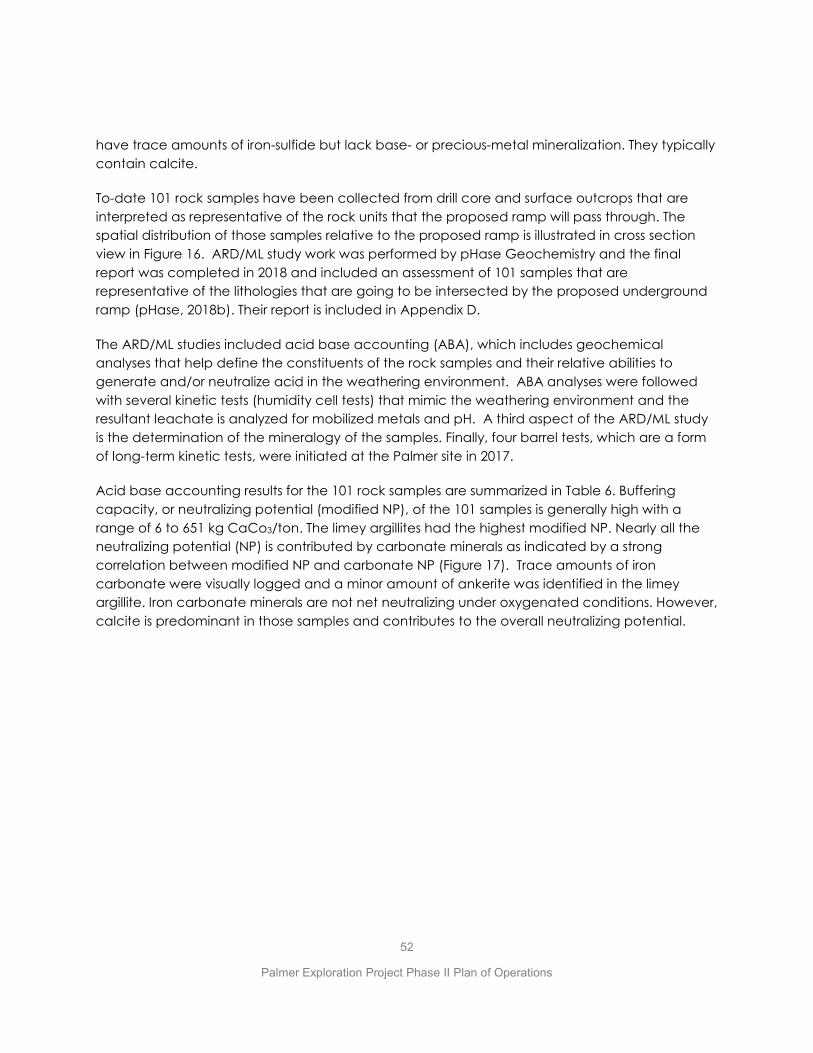
52
Palmer Exploration Project Phase II Plan of Operations
have trace amounts of iron-sulfide but lack base- or precious-metal mineralization. They typically contain calcite.
To-date 101 rock samples have been collected from drill core and surface outcrops that are interpreted as representative of the rock units that the proposed ramp will pass through. The spatial distribution of those samples relative to the proposed ramp is illustrated in cross section view in Figure 16. ARD/ML study work was performed by pHase Geochemistry and the final report was completed in 2018 and included an assessment of 101 samples that are representative of the lithologies that are going to be intersected by the proposed underground ramp (pHase, 2018b). Their report is included in Appendix D.
The ARD/ML studies included acid base accounting (ABA), which includes geochemical analyses that help define the constituents of the rock samples and their relative abilities to generate and/or neutralize acid in the weathering environment. ABA analyses were followed with several kinetic tests (humidity cell tests) that mimic the weathering environment and the resultant leachate is analyzed for mobilized metals and pH. A third aspect of the ARD/ML study is the determination of the mineralogy of the samples. Finally, four barrel tests, which are a form of long-term kinetic tests, were initiated at the Palmer site in 2017.
Acid base accounting results for the 101 rock samples are summarized in Table 6. Buffering capacity, or neutralizing potential (modified NP), of the 101 samples is generally high with a range of 6 to 651 kg CaCo3/ton. The limey argillites had the highest modified NP. Nearly all the neutralizing potential (NP) is contributed by carbonate minerals as indicated by a strong correlation between modified NP and carbonate NP (Figure 17). Trace amounts of iron carbonate were visually logged and a minor amount of ankerite was identified in the limey argillite. Iron carbonate minerals are not net neutralizing under oxygenated conditions. However, calcite is predominant in those samples and contributes to the overall neutralizing potential.
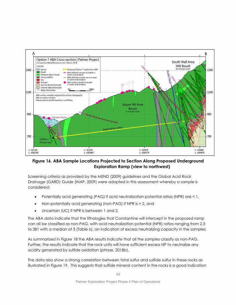
53
Palmer Exploration Project Phase II Plan of Operations
Figure 16. ABA Sample Locations Projected to Section Along Proposed Underground Exploration Ramp (view to northwest)
Screening criteria as provided by the MEND (2009) guidelines and the Global Acid Rock Drainage (GARD) Guide (INAP, 2009) were adopted in this assessment whereby a sample is considered:
x Potentially acid generating (PAG) if acid neutralization potential ratios (NPR) are < 1,
x Non-potentially acid generating (non-PAG) if NPR is > 2, and
x Uncertain (UC) if NPR is between 1 and 2.
The ABA data indicate that the lithologies that Constantine will intercept in the proposed ramp can all be classified as non-PAG, with acid neutralization potential (NPR) ratios ranging from 2.5 to 381 with a median of 3 (Table 6), an indication of excess neutralizing capacity in the samples.
As summarized in Figure 18 the ABA results indicate that all the samples classify as non-PAG. Further, the results indicate that the rock units will have sufficient excess NP to neutralize any acidity generated by sulfide oxidation (pHase, 2018b).
The data also show a strong correlation between total sulfur and sulfide sulfur in these rocks as illustrated in Figure 19. This suggests that sulfide mineral content in the rocks is a good indication
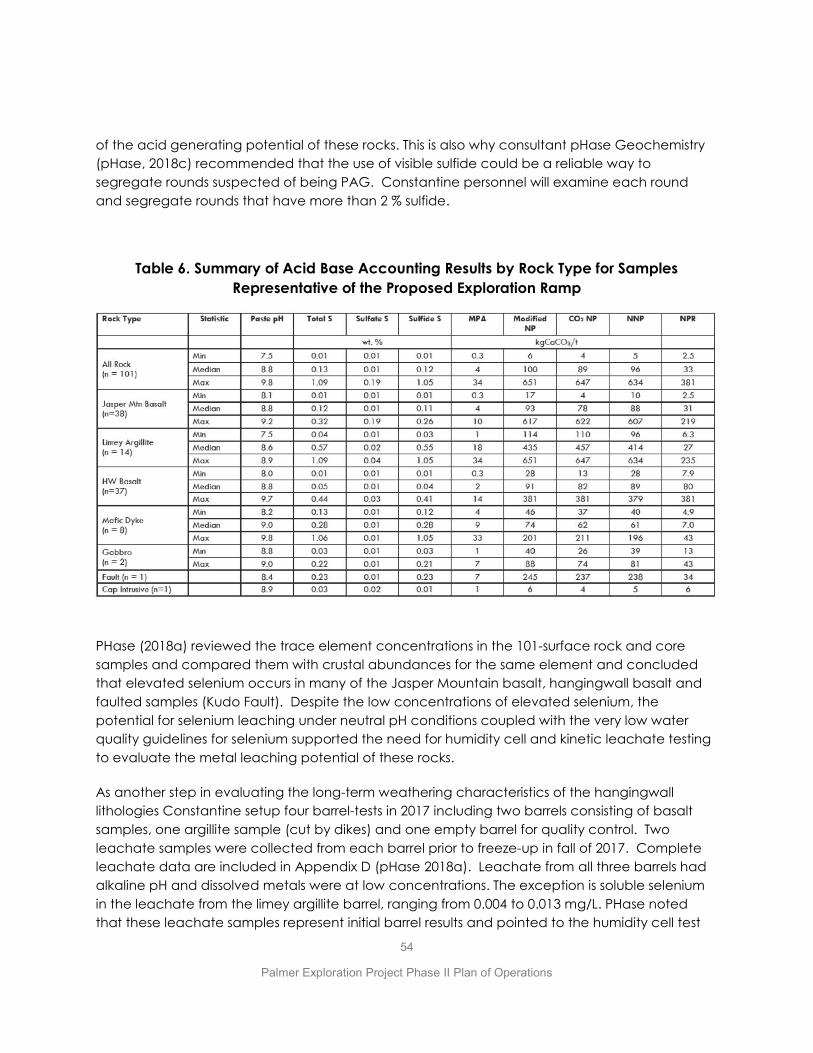
54
Palmer Exploration Project Phase II Plan of Operations
of the acid generating potential of these rocks. This is also why consultant pHase Geochemistry (pHase, 2018c) recommended that the use of visible sulfide could be a reliable way to segregate rounds suspected of being PAG. Constantine personnel will examine each round and segregate rounds that have more than 2 % sulfide.
Table 6. Summary of Acid Base Accounting Results by Rock Type for Samples Representative of the Proposed Exploration Ramp
PHase (2018a) reviewed the trace element concentrations in the 101-surface rock and core samples and compared them with crustal abundances for the same element and concluded that elevated selenium occurs in many of the Jasper Mountain basalt, hangingwall basalt and faulted samples (Kudo Fault). Despite the low concentrations of elevated selenium, the potential for selenium leaching under neutral pH conditions coupled with the very low water quality guidelines for selenium supported the need for humidity cell and kinetic leachate testing to evaluate the metal leaching potential of these rocks.
As another step in evaluating the long-term weathering characteristics of the hangingwall lithologies Constantine setup four barrel-tests in 2017 including two barrels consisting of basalt samples, one argillite sample (cut by dikes) and one empty barrel for quality control. Two leachate samples were collected from each barrel prior to freeze-up in fall of 2017. Complete leachate data are included in Appendix D (pHase 2018a). Leachate from all three barrels had alkaline pH and dissolved metals were at low concentrations. The exception is soluble selenium in the leachate from the limey argillite barrel, ranging from 0.004 to 0.013 mg/L. PHase noted that these leachate samples represent initial barrel results and pointed to the humidity cell test

55
Palmer Exploration Project Phase II Plan of Operations
(see below) that illustrate that there is a reduction in soluble metals in the leachate as the test program continues, which is the case for selenium in the humidity test cells as illustrated in Figure 20 (pHase 2018c).
Mineralogical examination was performed on the samples used for the barrel tests. Predominant minerals in the three principal hangingwall lithologies (volcanics, sediments and dikes) include quartz, feldspars, chlorite and calcite. Minor amounts of kaolinite, apatite, iron oxides, pyrite and titanium minerals were also identified. Calcite content ranges from ~7% to 26%. Pyrite in minor amounts was the predominant sulfur-bearing mineral identified in the samples, with negligible copper sulfides, galena and sphalerite. Overall, total sulfide in the rocks provide a good approximation of the sulfide-sulfur in the waste rock samples due to low concentrations of other sulfur sources such as sulfate-sulfur. Carbonate in the form of calcium carbonate occurs in all lithologies in the hangingwall.
Constantine intends to monitor development rock as it is hauled to the surface during ramp development. Based on the ABA data derived from the previously described characterization program Constantine will temporarily segregate any round that contains more than 2% sulfide, sample the round and submit the sample to ABA analyses. Rounds that are determined to be PAG based on the ABA analyses will eventually be placed back underground. Non-PAG rounds will be repurposed on the surface in one of the snow deflection structures, for construction or in one of the rock dumps. Monitoring of the development rock is discussed in more detail in the Monitoring Plan in Appendix A.
Figure 17. Comparison of Modified Neutralizing Potential with Carbonate Neutralizing Potential (pHase, 2018b)

56
Palmer Exploration Project Phase II Plan of Operations
Figure 18. ABA Results for Development Rock Samples (pHase, 2018b)
Figure 19. Comparison of Total Sulfur Versus Sulfide-Sulfur for Development Rock Samples (pHase, 2018b)
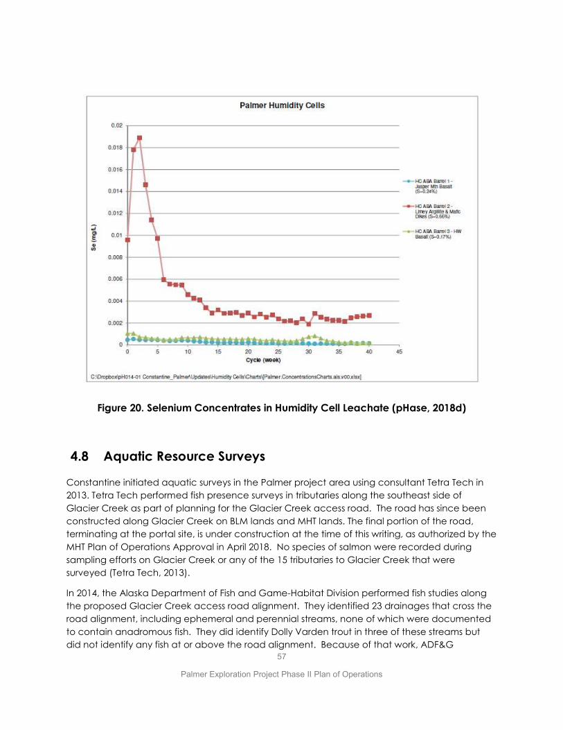
57
Palmer Exploration Project Phase II Plan of Operations
Figure 20. Selenium Concentrates in Humidity Cell Leachate (pHase, 2018d)
4.8 Aquatic Resource Surveys
Constantine initiated aquatic surveys in the Palmer project area using consultant Tetra Tech in 2013. Tetra Tech performed fish presence surveys in tributaries along the southeast side of Glacier Creek as part of planning for the Glacier Creek access road. The road has since been constructed along Glacier Creek on BLM lands and MHT lands. The final portion of the road, terminating at the portal site, is under construction at the time of this writing, as authorized by the MHT Plan of Operations Approval in April 2018. No species of salmon were recorded during sampling efforts on Glacier Creek or any of the 15 tributaries to Glacier Creek that were surveyed (Tetra Tech, 2013).
In 2014, the Alaska Department of Fish and Game-Habitat Division performed fish studies along the proposed Glacier Creek access road alignment. They identified 23 drainages that cross the road alignment, including ephemeral and perennial streams, none of which were documented to contain anadromous fish. They did identify Dolly Varden trout in three of these streams but did not identify any fish at or above the road alignment. Because of that work, ADF&G

58
Palmer Exploration Project Phase II Plan of Operations
determined that fish habitat permits were not required for any of the proposed stream crossings along the proposed road alignment or for Hangover and Waterfall creeks in upper Glacier Creek (ADF&G, 2014; 2018). In addition, ADF&G made a formal submission to modify the Alaska Anadromous Fish Catalog, by moving the upstream extent of coho salmon presence DOWNSTREAM on Glacier Creek, to an unnamed stream below the washed-out bridge on Porcupine Road. Figure 21 illustrates the extent of resident fish and the modifications to the catalog for anadromous fish along lower Glacier Creek.
ADF&G made trips to the site again in 2015, 2016, 2017 and 2018 for the purposes of furthering their survey work. Surveys were conducted for sediments, periphyton, benthic invertebrates, and metal concentration in fish tissues in 2016, 2017, and 2018. The latest surveys confirmed the absence of fish in the upper tributaries to Glacier Creek (ADF&G 2018a). ADF&G published reports titled Glacier Creek Aquatic Studies for their work in 2016, 2017 and 2018(b) that are available online at: http://www.adfg.alaska.gov/index.cfm?adfg=habitat_publications.main
4.9 WILDLIFE, TERRESTRIAL ECOSYSTEM AND VEGETATION SURVEYS
Wildlife and Terrestrial studies were initiated by consultant Hemmera in 2014 and performed seasonally through 2018. Wildlife habitat mapping and assessment for suitability for wildlife species of interest was done and resident species of interest were identified (Hemmera 2015a, 2015b). No endangered species are known or likely to occur in the Project area. Surveys were conducted for song birds and birds of prey and Mountain Goat populations in the project area are seasonally surveyed (Hemmera, 2016; 2018). Hemmera’s baseline summary reports are included in Appendix D.
Incidental wildlife observations are reported by Palmer Project employees using digital geo-referenced reporting forms. Constantine personnel have identified the following wildlife in the area: black and brown bear, mountain goat, coyote, wolf, red fox, moose, Steller’s Jay, Rock Ptarmigan, Belted Kingfisher, Golden Eagle, Red-tailed Hawk, Hoary Marmot and ground squirrels.
Constantine has developed an invasive species management plan for the BLM (developed for the first portion of the Glacier Creek access road which is on BLM land) and the entire project will benefit from its implementation regardless of land ownership.

59
Palmer Exploration Project Phase II Plan of Operations
Figure 21. Reach of Anadromous and Resident Fish in Glacier Creek
4.10 Wetlands Surveys
Constantine engaged consultant HDR, Inc. to perform wetlands delineation work in 2013 including mapping approximately 233 acres of land along a corridor for the proposed Glacier Creek access road. That segment of the road was constructed in 2016-2018. In 2014 and 2017 HDR also completed an office-based wetland mapping effort that focused on an area comprising 12,800 acres. In 2018 HDR prepared a wetlands jurisdictional determination report encompassing certain areas included in the previous studies and new areas surrounding them for a total 2017 study area of 4,580 acres (HDR, 2018). The wetlands mapping coverage is illustrated in Figure 22. The 2018 HDR report is included in Appendix D.

60
Palmer Exploration Project Phase II Plan of Operations
Figure 22. Extent of Wetlands Mapping in the Palmer Project Area
4.11 Cultural Resources (Archeological) Surveys
Archeological surveys have been performed within areas of potential disturbance through 2017 by consultant Northern Land Use Research (NLUR). This includes areas subject to disturbance because of all currently anticipated project surface activities. No cultural sites or artifacts have been identified. These surveys were performed under the permit authority of the Office of History and Archaeology/State Historic Preservation Office. The 2017 NLUR cultural resource report is included in Appendix D.
Proposed Portal Location
61
Palmer Exploration Project Phase II Plan of Operations
5.0 RECLAMATION AND CARE & MAINTENANCE PLANS
This Phase II reclamation plan is designed to meet the State of Alaska regulatory requirements for a reclamation plan. Constantine has prepared plans for both temporary closure and permanent closure scenarios which are described below with additional details in Appendix C. This reclamation plan and reclamation cost estimate supersede the reclamation plan and cost estimate included in Constantine’s Phase I Plan of Operations and approved under by ADNR Reclamation Plan Approval #J20185690RPA. This Phase II reclamation plan and cost estimate includes all the reclamation activities from the Phase I reclamation plan but has been expanded to include reclamation activities required for the additional impacts of the proposed underground program (Phase II) as well.
5.1 Care and Maintenance Plan for Temporary Closure
There are some situations where Constantine may elect to suspend its activities proposed under this Phase II Plan of Operations for periods longer than the seasonal interruptions that are common to mineral exploration. Under any situation where activities at the site will cease for more than 1 year and for up to 3 years Constantine would take the steps necessary to put the site on a care and maintenance status and continue to perform all maintenance, monitoring and reporting tasks that are necessary to protect public health and the environment during the temporary closure. Should Constantine decide to suspend activities for more than 1 year it will notify the Trust, ADNR and ADEC within 45 days of making that decision. The Care and Maintenance Plan for the temporary closure scenario is included in Appendix C and includes the following key components:
x Continuation of baseline water quality monitoring at select sites,
x Installation of a gate to discourage public vehicular access onto Trust lands.
x Continuation of seasonal groundwater quality monitoring at the monitoring wells up- and down-gradient of the lower diffuser, as long as water is being discharged through the lower diffuser,
x Continuation of discharge of underground seepage water through the LAD disposal system,
x Compliance with the SWPPP, including visual inspections and maintenance of stormwater BMP’s during the ice-free months,
x Installing a barrier at the portal to restrict public access to the underground development ramp,
62
Palmer Exploration Project Phase II Plan of Operations
x Compliance with the SPCC Plan including visual monitoring and management of fuel storage facilities including maintenance of secondary containment vessels when fuel is stored on site during Care & Maintenance.
x Monthly visual monitoring of site roads, laydown areas and portal pad area during ice- free months for any conditions that warrant repair or other response.
5.2 Reclamation Plan for Permanent Closure
If Constantine decides to cease activities at the site permanently, it will perform the activities prescribed in the Reclamation Plan for Permanent Closure included in Appendix C. Those activities are summarized below:
x Constantine will update its water management plan incorporating underground seepage water quality and quantity data and confirm the need for installation of a hydraulic portal plug in the development ramp to minimize the flow of underground seepage water to the surface at the portal. Constantine’s base assumption is that it will install a hydraulic portal plug in the development ramp at closure. Constantine has included the estimated costs for the portal plug design and installation in the reclamation cost estimate. In the absence of a need to install a hydraulic plug, Constantine will install a barricade on the portal that will provide a barrier to protect public safety and keep out the public and wildlife.
x Constantine will consult with the Mental Health Trust to identify any surface infrastructure that the Trust wants left in place at final closure. Presently Constantine understands the Trust prefers that the access road up to the portal pad remain in place for the long term. Accordingly, costs for reclaiming the access road on MHT lands are not included in the reclamation cost estimate
x Constantine will remove all surface facilities and appurtenances (buildings, ponds, exposed piping, secondary roads, fuel storage facilities, etc.) and materials (supplies, fuel, tanks, debris, explosives, chemicals, etc.), except those that the Trust requests to be left in-place or that are required for long-term monitoring and maintenance. Presently Constantine anticipates that there will not be any facilities required for long-term water management and has not included any costs associated with operating or maintaining any facilities following reclamation of the site in accordance with the Reclamation Plan.
x Constantine will reclaim the disturbed areas by recontouring as necessary, distributing any salvaged soil and reseeding, to provide short-term stability from erosion and encourage long-term re-establishment of native plant species. Constantine will consult with the Alaska Plant Materials Research Center to develop a strategy for revegetation including identifying the appropriate seed mix to use for revegetation disturbed areas. There will not be an effort to place topsoil on the development rock or reseed it. As a practical matter, the glaciofluvial material that overlies bedrock in most of upper Glacier
63
Palmer Exploration Project Phase II Plan of Operations
Creek is too immature to have developed a salvageable organic topsoil horizon. As a result, little topsoil has been salvaged and Constantine anticipates that it will be reseeding directly onto this glaciofluvial material during reclamation. Undisturbed glaciofluvial material in upper Glacier Creek currently supports predominantly alder and subordinate devils club.
x Constantine has included the costs for monthly site inspections and reporting during the snow-free months for a two-year period following completion of the reclamation activities described above. The principle purpose of the monitoring is to monitor seepage from the portal as a measure of the efficacy of the portal plug in reducing seepage to de-minimis levels.
x In the unlikely event that any confirmed PAG material is identified during the underground development program, that material will be placed back underground prior to installing the hydraulic portal plug.
Activities associated with permanent closure focus initially on installation of the portal plug which will require a contract miner crew to perform using concrete supplied by truck from a batch plant in Haines. The cost estimate assumes that the contract miner crew and their underground equipment and supplies will have to be mobilized to site to perform the work. It also assumes they will have to supply electric generators and air compressors for the work. Once mobilized the first task would be to haul PAG from the surface to underground. While the costs for this are included in the cost estimate no PAG is expected in the program. Construction of the portal plug is expected to take 3 weeks followed by another 3 weeks to let the plug cement cure. During the cure time water will continue to be discharged through a pipe in the plug to the LAD discharge point. Once the portal plug cement is cured the through-pipe will be closed and deconstruction of the LAD can proceed. The entire process is expected to take approximately 12 weeks.
5.3 Financial Assurance and Estimated Costs for Reclamation and Care and Maintenance
Constantine has calculated estimated costs for both the care and maintenance under the temporary closure scenario and reclamation for permanent closure. Temporary and permanent closure scenarios are also described in Appendix C. Constantine intends to post a financial assurance in a form acceptable to the State regulatory agencies prior to initiating any work under this Plan of Operations, once the Plan of Operations is approved by the MHT and the Reclamation Plan is approved by ADNR.
Constantine’s estimated cost for the care and maintenance under the temporary closure scenario is: 1) $33,245 to stabilize the site and make it ready for Care and Maintenance and install an access road gate and portal barrier, plus 2) $15,180/year for twice-monthly inspections and monthly reporting for each year that it remains in Care and Maintenance status. Assuming
64
Palmer Exploration Project Phase II Plan of Operations
a 3-year duration on Care & Maintenance status, the total cost is estimated to be $105,454 including indirect costs per ADNR guidance. At the end of 3 years Constantine must either request an extension of the Care and Maintenance status from ADNR or permanently close the site in accordance with the Reclamation Plan for permanent closure.
Constantine’s estimated reclamation cost for permanent closure of the site is $1,011,542. This includes $522,181 in direct costs to design and construct a hydraulic portal plug in the development ramp to reduce surface flows at the portal to de minimis levels.
The permanent closure cost estimate includes indirect costs in accordance with ADNR guidance. In determining the Indirect rate for each of the 7 categories of Indirect Costs, we referred to the DOWL (2015) report for the discussion of factors affecting the range of indirect costs in each category. In general owing to the low risk (no PAG, good predicted water quality, low project uncertainty, good access, the lack of project complexity, fact that equipment rates already include contractor profit, history of civil contractor experience on site, and the low overall direct cost of the reclamation, and manageable climate the guidance suggests using the lower range of indirect costs, with some exceptions. The following is a discussion of the factors Constantine considered in selecting the indirect costs.
Contractor Profit – ADNR guidelines (DOWL, 2015) recommend a range of 6-10% of direct costs. Most of the reclamation costs for the project are civil works costs and the cost estimate is based on quotes from a local contractor who has performed years of civil work on the project. Contractor profit is already included in the contractor’s hourly equipment rates used for the cost estimate. As a result, Constantine feels that the low end (6%) of the indirect range is appropriate for contractor profit.
Contractor Overhead – ADNR guidelines (DOWL, 2015) recommend a range of 4-8% of direct costs. As with contractor profit, contractor overhead is already built into the contractor’s hourly rates for equipment, including the equipment operator, fuel and repairs. While the guidelines point out that there is often higher overhead costs for smaller projects, our use of local contractor rates negates this idea for the Palmer project. Nonetheless Constantine did not choose the lowest value but used 5% for contractor overhead in the cost estimate.
Performance and Payment Bonds - ADNR guidelines (DOWL, 2015) recommend a range of 2.5-3.5% of direct costs. Constantine concluded that the low end of the range was appropriate for the Palmer project owing to the low overall cost of reclamation, the simplicity of the project, past performance of local contractors and relatively few number of contractors/subcontractors required to perform the reclamation.
Liability Insurance - ADNR guidelines (DOWL, 2015) recommend 1.5% of labor costs. This is a fixed percentage according to the guidelines.
Contract Administration - ADNR guidelines (DOWL, 2015) recommend a range of 5-9% of direct costs. According to the guidelines this category of indirect costs is to cover the cost of hiring a
65
Palmer Exploration Project Phase II Plan of Operations
project management firm to inspect and supervise the reclamation work. The guidelines go on to state that the contract administration amount accepted be the state will be based on size of the bond, project closure complexity and duration of the active reclamation phase. The guidelines also describe factors like access, climate and mine maturity. On one hand the guidelines say that in general larger projects may require a lower percentage of contract administration costs compared to small or mid-size projects. But on the other hand, the guidelines offer that while scale may warrant lower contract administration costs, project complexity may push these costs to the top of the range. In addition, Constantine already has a project lead (supervisor) built into each of the tasks that comprise the entire reclamation project, including meals and accommodations for the lead. Constantine also included engineering supervision costs in the direct costs for the portal plug. Arguably this is the single component of the reclamation activities that requires engineering support and inspecting. Constantine considered all these factors and concluded that the inclusion of supervision (including support costs) in the cost estimate, lack of project complexity, ease of access, moderate weather, and the general lack of the requirement for inspections of engineered facilities (lack of engineered covers, engineered water management components) all justify using a contract administration value in the lower half of the range (5-9%). Constantine used 6% in the cost estimate
Engineering Redesign - ADNR guidelines (DOWL, 2015) recommend a range of 3-7% of direct costs. Engineering redesign costs are meant to bring conceptual closure plan designs to ready-for construction designs. The guidelines use scale to mean that bigger mines often have performed more closure design work by the time closure occurs. This is true for more mature mines but not necessarily for immature, complex mines. Reclamation at Palmer is mostly simplistic recontouring operations and removal of pipe. The only required complicated engineering design is for the portal plug and the direct cost estimate includes $113,000 specifically for geotechnical studies, engineering design (conceptual to final) and professional engineering management/oversight during entire construction of the portal plug. Owing to the inclusion of geotechnical work, engineering design and professional engineering supervision costs in the direct cost for the portal plug and the otherwise simplistic nature of the reclamation itself, Constantine concluded that 3% is sufficient for engineering redesign component of indirect costs.
Scope Contingency - ADNR guidelines (DOWL, 2015) recommend a range of 6-11% of direct costs. Owing to the narrow scope and simplicity of the reclamation work, and familiarity that local contractors have with the site, Constantine chose 6% for scope contingency.
Bid Contingency - ADNR guidelines (DOWL, 2015) recommend a range of 4-9% of direct costs. The guidelines offer that this contingency might be lower for larger projects there would be project efficiencies realized over the life of the reclamation project. Constantine believes that the years of experience gained at the site by the few civil contractors in Haines essentially has the same effect. Namely that any of those contractors know how to bid any work at Palmer and make it cost effective for them. Constantine did not choose the lowest in the range but chose 5% for bid contingency.
6.0 REFERENCES
ADFG. 2018a. Waterfall and Hangover Creeks Fish Investigations. Alaska Department of Fish and Game Memorandum prepared by Dylan Krull for Jackie Timothy. October 22 2018. 4 pp. (APPENDIX D11)
ADFG. 2018b. Legere, N. M. and K. M. Kanouse. Glacier Creek aquatic studies, 2018. Alaska Department of Fish and Game, Technical Report No. 18-09, Douglas, AK. 118 pp.
ADFG. 2017. Legere, N. M. and K. M. Kanouse. Glacier Creek aquatic studies, 2017. Alaska Department of Fish and Game, Technical Report No. 17-11, Douglas, AK. 114 pp.
ADFG. 2016. Kanouse, K. M and N. M. Legere. Glacier Creek aquatic studies, 2016. Alaska Department of Fish and Game, Technical Report No. 16-10, Douglas, AK. 137 pp.
ADFG. 2014. Glacier Creek Investigation Trip Report. Alaska Department of Fish and Game Memorandum prepared by Matthew Kern for Jackie Timothy. June 26 2014. 27 pp.
ADNR. 2002. Haines State Forest Management Plan. Alaska Department of Natural Resources. Division of Mining , Land & Water, Resource Assessment & Development Section. Division of Forestry. 212 pp.
BCME. 2015. Technical Guidance 7: Environmental Management Act. Assessing the Design, Size, and Operation of Sediment Ponds Used in Mining. Version 1.0. British Columbia Ministry of the Environment. Environmental Protection Division. 23 pp.
BGC. 2018a. Final Design Report for Sediment Ponds, Temporary Rock Storage, LAD, and Diffuser System. Prepared by BGC Engineering Inc, for Constantine North Inc. December 11 2018. 172 pp.
BGC. 2018b. Sedimentation Ponds and Land Application Area Site Investigation. Prepared by BGC Engineering Inc. for Constantine Mining LLC. March 2 2018. 70 pp. (APPENDIX D12)
BLM. 2012. Ring of Fire, Draft Resource Management Plan Amendment / Draft Environmental Impact Statement. Haines Planning Area Amendment. December 14, 2012. U.S. Department of the Interior. Bureau of Land Management. 204 pp.
DOWL. 2015. Mine Closure and Reclamation Cost Estimation Guidelines. Prepared by DOWL for ADNR and ADEC.
Haines Borough. 2012. Haines Borough 2025 Comprehensive Plan. September 2012. 392 pp.
HDR. 2018. Jurisdictional Determination report. Palmer Exploration Project, Haines Alaska. Prepared by HDR for Constantine North Inc. January 2018. 160 pp. (APPENDIX D6)
Hemmera. 2018. Terrestrial Wildlife. Mountain Goat Studies: 2015-2018. Prepared by Hemmera Envirochem Inc. for Constantine Mining LLC. May 25, 2018. 45 pp. (APPENDIX D9)

Hemmera. 2016. Terrestrial Wildlife. Baseline studies for Passerines, Mountain Goat and Cliff-nesting Raptors. Palmer Project Site. Prepared by Hemmera Envirochem Inc. for Constantine Metal Resources. March 2016. 76pp. (APPENDIX D8)
Hemmera. 2015a. Terrestrial Wildlife and Habitat Assessment. Palmer Project Site. Prepared by Hemmera Envirochem Inc for Constantine Metal Resources Ltd. May 2015. 83pp. (APPENDIX D7)
Hemmera. 2015b. Existing Conditions Report – Invasive Plant Species. Prepared by Hemmera Envirochem Inc for Constantine Metal Resources Ltd. November 2015. 74pp.
INAP. 2009. Global Acid Rock Drainage Guide (GARD Guide). The International Network for Acid Prevention (INAP). http://www.gardguide.com.
Integral. 2018a. Palmer Project Baseline Surface Water Quality. Memorandum prepared by Alice Conovitz of Integral Consulting Inc. for Constantine Mining LLC. October 16 2018. 374 pp. (APPENDIX D1)
Integral. 2018b. Quality Assurance Project Plan for Baseline Water Quality Monitoring. Prepared by Integral Consulting Inc. for Constantine Mining LLC. October 2018. 167 pp. (APPENDIX A)
Integral. 2018c. Klehini River and Glacier Creek Hydrologic Data Summary—Spring 2018 Update. Memorandum prepared by Alice Conovitz of Integral Consulting Inc. for Constantine North. April 30 2018. 30 pp. (APPENDIX D2)
Integral. 2018d. Palmer Project Baseline Groundwater Quality. Memorandum prepared by Alice Conovitz of Integral Consulting Inc. for Constantine Mining LLC. October 15 2018. 127 pp. (APPENDIX D3)
MEND. 2009. Prediction Manual for Drainage Chemistry from Sulphidic Geologic Materials. Report 1.20.1. 579 pp.
NLUR. 2017. Cultural Resources Survey for the Palmer Project, Glacier Creek, Southeast Alaska. Prepared by Northern Land Use Research Alaska LLC. July 2017. 36 pp.
pHase. 2018a. Geochemical Source Term Predictions, Palmer Project. Prepared by pHase Geochemisty for Constantine North Inc. November 25 2018. 38 pp. (APPENDIX D13)
pHase. 2018b. Geochemical Characterization in Support of a Proposed Exploration Drift, Palmer Project. Prepared by pHase Geochemistry for Constantine North Inc. December 4 2018. 181 pp. (APPENDIX D5)
pHase. 2018c. ARD/ML Monitoring and Management Plan for Exploration Drift Development, Palmer Project. Prepared by pHase Geochemisty for Constantine North Inc. December 4 2018. 14 pp. (APPENDIX D10)
pHase. 2018d. Final Humidity Cell Test Results, Palmer Project. Prepared by pHase Geochemisty for Constantine North Inc. November 8 2018. 61 pp.
SLR. 2018. Air Quality Applicability Determination. Prepared by SLR for Constantine Mining LLC. July 2018. 54 pp.

Tetra Tech. 2013. Palmer VMS Project. Preliminary Aquatic Investigation. Prepared for Constantine North Inc by Tetra Tech. October 2013. 22 pp.
Tundra. 2018a. 2017 Hydrogeology Report. Palmer Exploration Project, Haines, Alaska. Prepared by Tundra Consulting LLC for Constantine North Inc, February 23 2018. 118 pp. (APPENDIX D4)
Tundra. 2018b. 2018 Groundwater Level Monitoring Report. Palmer Exploration Project. Prepared by Tundra Consulting LLC for Constantine Mining LLC, December 21 2018. 48 pp.

APPENDIX/DIVIDER TITLE

A
MONITORING PLAN

B
WATER MANAGEMENT PLAN

C
TEMPORARY CLOSURE AND FINAL RECLAMATION PLANS
D
BASELINE ENVIRONMENTAL DATA AND SUMMARY REPORTS
D.1 Surface Water Quality (Integral 2018)
D.2 Surface Water Quantity (Integral 2018)
D.3 Groundwater Quality (Integral 2018)
D.4 Groundwater Hydrogeology (Tundra 2018)
D.5 Development Rock Characterization (pHase 2018)
D.6 Wetlands (HDR 2017)
D.7 Wildlife Report (Hemmera 2015)
D.8 Terrestrial Habitat (Hemmera 2016)
D.9 Goat Summary Report (Hemmera 2018)
D.10 MLARD Monitoring and Management Plan for Exploration Drift Development, Palmer Project (pHase 2018)
D.11 Hangover and Waterfall Creeks Fish Investigation (ADFG 2018)
D.12 LAD Infiltration Tests (BGC 2018)
D.13 Geochemical Source Term Predictions (pHase 2018)