palmsight: an assistive technology helping the blind to ... · attached on the back of the same...
TRANSCRIPT

PalmSight: an assistive technology helping the blind to locate and grasp objects
Zhixuan Yu, Samantha Horvath, Alexandra Delazio, Jihang Wang, Rebeka Almasi, Roberta Klatzky, John Galeotti, George Stetten
CMU-RI-TR-16-59
The Robotics Institute Carnegie Mellon University
Pittsburgh, Pennsylvania 15213
December, 2016
Copyright 2016

2
Abstract
In this technical report, we introduce a novel hand-mounted intelligent device called PalmSight that aims at helping the blind and visually impaired identify, locate, and grasp an object in their surroundings. The present implementation of PalmSight acquires stereo visual information through a binocular camera mounted on user’s palm and provides haptic feedback via five vibrators attached on the back of the same hand, which direct the user to grasp the target object. A standard laptop computer is used to receive and process the acquired visual information, and then generate corresponding control signals for the five vibrators. PalmSight uses computer vision methods to identify and locate the target in 3D, and subsequently to realize vision-to-touch substitution. This assistive technology is an extension of the previous research in our laboratory on a device called FingerSight, which translates visual information to haptics stimulation on an individual finger for use in localization, navigation, and control by the blind and visually impaired. This report is submitted in partial fulfillment of the requirements for the degree of Master of Science in Biomedical Engineering at Carnegie Mellon University for Zhixuan Yu.
Index terms: Blind, visually impaired, assistive technology, haptics, sensory substitution,
computer vision.

3
Acknowledgements
Supported by NIH 1R01EY021641, NSF GRFP 0946825, and Research to Prevent Blindness.

4
Table of Contents
Abstract.............................................................................................................................2
Acknowledgements...........................................................................................................3
TableofContents...............................................................................................................4
ListofFigures.....................................................................................................................5
1 Introduction................................................................................................................61.1 InitialExperimentandEnvisionedUse.............................................................................7
2 Methods.....................................................................................................................92.1 Systemcomponents.........................................................................................................9
2.1.1 Stereovisioncapturesystem.........................................................................................92.1.2 Hapticfeedbacksystem.................................................................................................92.1.3 StandardLaptopComputerwiththePalmSightApplicationProgram........................10
2.2 CameraCalibrationandRectification.............................................................................112.2.1 MonocularCalibration.................................................................................................112.2.2 StereoCalibration........................................................................................................142.2.3 StereoRectification......................................................................................................15
2.3 TargetDetectionandTracking.......................................................................................152.3.1 Detection.....................................................................................................................162.3.2 Tracking........................................................................................................................18
2.4 Depthperception...........................................................................................................182.4.1 Generateundistortedrectifiedimagepairs.................................................................192.4.2 Generatedisparitymap...............................................................................................202.4.3 Computedepthwithininterestarea...........................................................................20
2.5 Hapticfeedback.............................................................................................................212.5.1 Generatingthehapticsfeedbacksignal.......................................................................222.5.2 Communicationbetweenlaptopandvibrators...........................................................23
2.6 ProgramWorkflow........................................................................................................24
3 ExperimentalProtocolsandResults...........................................................................263.1 TactorArrayDiscrimination...........................................................................................263.2 EvaluationofPalmSightforreachingtotarget...............................................................26
4 DiscussionandConclusion.........................................................................................27
5 References.................................................................................................................29
6 Appendices................................................................................................................316.1 HardwareSchematic......................................................................................................316.2 LaptopSoftware............................................................................................................32
6.2.1 palmsight.h..................................................................................................................326.2.2 palmsight.cpp...............................................................................................................356.2.3 main.cpp......................................................................................................................46
6.3 WixelSoftware..............................................................................................................516.4 ExperimentalProtocol...................................................................................................53
6.4.1 PalmSightExperimentDocument................................................................................536.4.2 PalmSightSubjectInstructions....................................................................................57
5
List of Figures
Figure 1 PalmSight apparatus, including stereo cameras, tactors, associated hardware interface, and laptop computer. ............................................................................................................. 7
Figure 2 PalmSight apparatus used in experiment to locate target soda can. ................................ 8Figure 3 Stereo camera with Velcro strap for palmer mounting. .................................................. 9Figure 4 Tactor array with hardware interface. ........................................................................... 10Figure 5 Program display showing original camera view (lower right), camera view after
undistorting and rectification (upper right), depth map (lower left), and target camera coordinates (upper left). ....................................................................................................... 11
Figure 6 Image showing "fisheye" or "barrel" distortion. ........................................................... 13Figure 7 Calibration target. .......................................................................................................... 13Figure 8 Example of the calibration target image from a fisheye camera. .................................. 13Figure 9 Geometric relation between the two cameras in 3D space. ........................................... 14Figure 10 Example of stereo images for calibration of the binocular system. ........................... 14Figure 11 Camera calibration and rectification work flow. ......................................................... 15Figure 12 Model training work flow. ........................................................................................... 16Figure 13 Detection workflow in PalmSight. .............................................................................. 17Figure 14 Original (top) and undistorted rectified (bottom) image pairs .................................... 19Figure 15 Depth map (left) and one image from the corresponding stereo images pair (right). . 20Figure 16 Geometry of depth computation. ................................................................................. 21Figure 17 Regions of right camera image used to determine haptic feedback. ........................... 22Figure 18 Communications control byte for vibrators (tactors). ................................................. 23Figure 19 Core work flow of the PalmSight program ................................................................. 24Figure 20 Experiment to determine optimal placement of vibrators. .......................................... 26Figure 21 Schematic of hardware interface for vibrator activation (note optional hardware
oscillator for 50% duty cycle, not used when software controls duty cycle). ..................... 31

6
1 Introduction
According to a National Health Interview survey in 2012, more than 20 million adults in the United State suffer from significant visual impairment [1]. Vision is the most important perceptual channel, accounting for a large percentage of the information people acquire in daily life. At present, most visually impaired people rely on white canes and service dogs for navigation, as well as their sense of touch for identifying objects to grasp and manipulate Such methods are essentially unchanged from twenty years ago [2].
The task of picking up specific objects is extremely common, to drink a cup water or answer a cell phone. In those with normal vision, such tasks are accomplished through hand-eye coordination. However, the visually impaired usually rely on touch to locate objects they want to pick up, which, in turn, may not be very efficient. Therefore, there exists a need for a device that provides the visually impaired with the ability to identity and locate objects around them, and subsequent guidance to grasp those objects, thus making the accomplishment of this everyday task more convenient.
Many devices for the visually impaired are designed with the concept of sensory substitution, circumventing the loss of one sense by feeding the information through another channel [3]. Sensory substitution systems generally consist of three components: a sensor that collects a signal, a coupling system that processes that signal, and finally an output transducer, which transmits the signal to a sense organ not normally used for that signal [4] [5]. There are many technologies use the auditory sense as the substitution for the visual sense taking advantage of the high-bandwidth attribute of hearing. However, we are specifically focused on vision-to-touch substitution rather than hearing, since hearing is usually well-developed for visually impaired people and provides them with essential environmental acoustic cues.
A variety of vision-to-touch sensory substitution systems have been developed. Some employ tactile arrays that feature a grid of small pins with adjustable heights to depict the captured image, which are interrogated by fingers in an effort to “visualize” the image [6]. Others use electrode arrays placed on the tongue to relay visual information [7]. Our general approach, first put forth in our FingerSight device, differs by providing for searching the visual environment more directly, using hand and finger motion to couple the view from a miniature camera and a vibrator [8] [9].
PalmSight, which we introduce in this paper, is a vision-to-touch sensory substitution system (Figure 1) with stereo cameras mounted on the user’s palm and vibrators on the back of the same hand. The captured visual information is processed by computer vision algorithms to determine the presence of a target object and compute its approximate position in 3D space relative to the user’s hand. This information is processed in real-time and communicated to the user by the vibrators. PalmSight relies on the computer to make the high-level judgment, e.g. whether the target object is identified and what its relative location is to the hand. This differs a from previous systems from our laboratory, called FingerSight, which relied on substitution of more primitive visual features such as edges [8], and assigned the user the task of integrating such information by moving the finger-mounted camera. Our present approach is thus a potentially important application of computer vision in the field of assistive technology, placing emphasis on such algorithms that are presently experiencing rapid growth in capabilities and utilization throughout the field of computer vision.

7
Figure 1 PalmSight apparatus, including stereo cameras, tactors, associated hardware interface, and laptop computer.
1.1 Initial Experiment and Envisioned Use This paper describes the first PalmSight prototype, including hardware and software, as well as
the design for initial experiment using that prototype. At the time of this writing, institutional review board (IRB) approval has been obtained, and the experiments are just beginning to be performed Once sufficient data has been collected, we will describe the results in a future publication. It is, however, instructive to briefly describe the experiment here, to convey how we envision PalmSight being used.
In our initial planned experiments (see Figure 2), the PalmSight device will be employed as follows: First, the user searches the surroundings for a preselected target object by moving the hand around in different directions with the palm facing forward. In doing so, the user is instructed to stay in one pose for approximately 1 second and then turn approximately 30 degrees to the next pose, until some vibration is felt on the back of the hand, indicating the identification of the target object. Then, based on which of the 5 vibrators are activated, the user adjusts the position of the hand according to the haptic feedback, so as to have the palm face pointed more directly toward the target. Subsequently, the user moves the hand forward towards the target object with an indication of distance provided by the haptic feedback, possibly with additional slight adjustment of direction along the way. When the target is close enough to grasp, the user receives additional haptic feedback. During the procedure, the PalmSight device may lose track of the target object, which would require reestablishing tracking by moving the hand backward and/or reorienting the direction in which the hand is pointed.
A competing approach to PalmSight is a standard smartphone held in the non-reaching hand. Smartphones already comes equipped with one or more cameras and a vibrator, and they are
8
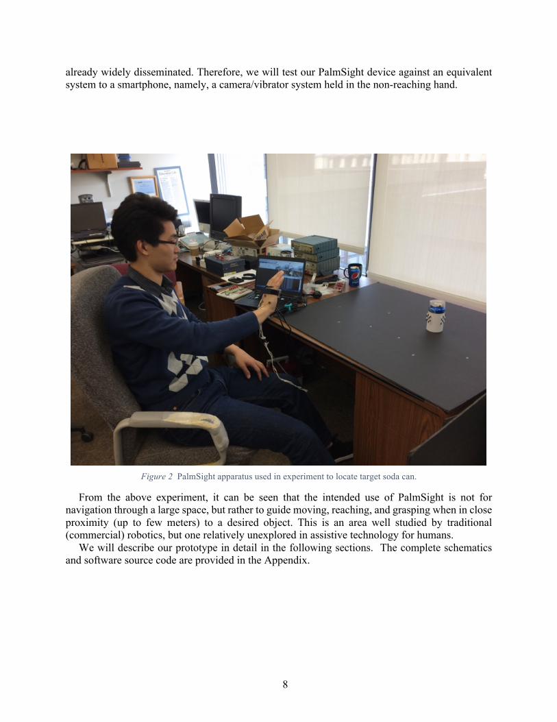
already widely disseminated. Therefore, we will test our PalmSight device against an equivalent system to a smartphone, namely, a camera/vibrator system held in the non-reaching hand.
Figure 2 PalmSight apparatus used in experiment to locate target soda can.
From the above experiment, it can be seen that the intended use of PalmSight is not for navigation through a large space, but rather to guide moving, reaching, and grasping when in close proximity (up to few meters) to a desired object. This is an area well studied by traditional (commercial) robotics, but one relatively unexplored in assistive technology for humans.
We will describe our prototype in detail in the following sections. The complete schematics and software source code are provided in the Appendix.

9
2 Methods
2.1 System components The overall PalmSight system consists of three physical components: (1) the stereo vision
capturing system, (2) the haptic feedback system, and (3) a standard laptop computer with the PalmSight application program. We briefly describe each in the following sections.
2.1.1 Stereo vision capture system
The stereo vision capture system is composed of a homemade binocular camera that contains two identical fisheye universal serial bus (USB) camera modules (Ailipu Technology Co., ELP-USBFHD01M 180 degree 1080p) fixed on an acrylic board, with an adjustable Velcro strap to attach the system onto user’s palm (Figure 3).
Figure 3 Stereo camera with Velcro strap for palmer mounting.
2.1.2 Haptic feedback system
The haptics feedback system is composed of five vibrators (Adafruit Vibrating Mini Motor Discs ADA1201), circuitry for driving those vibrators, and a programmable microcontroller (Wixel, Pololu, Inc.) for transmitting control signals via USB from the laptop to the circuitry (see Figure 4). Those five vibrators are attached to the back of user’s hand using a commercial product called glue dots (Glue Dots International) following the pattern shown in the picture. There are five red buttons on the breadboard, each activating one of the vibrator manually. We used this manual activation to test whether the user can differentiate the vibration of different vibrators. The vibrators can also be activated by the computer, as described next.

10
Figure 4 Tactor array with hardware interface.
2.1.3 Standard Laptop Computer with the PalmSight Application Program
We used a laptop computer (Dell Latitude E5450 2.2GHz) to perform the computer vision aspects of the system. The program on the laptop continuously receives stereo image pairs from the stereo cameras and processes that information using computer vision algorithms to determine the presence of a target object, and to compute the object’s approximate position in 3D space relative to the user’s hand. Based on these results, control signals for the five vibrators are generated and transferred to the haptic feedback system. The software on the laptop is listed in the Appendix starting on page 32.
As shown in Figure 5, the program opens three windows for displaying (1) the original camera view, (2) the camera view after undistorting and rectification (described later), and (3) a depth map, in which grayscale indicates distance. Calculated information about relative position of the target object is also printed on the terminal.

11
Figure 5 Program display showing original camera view (lower right), camera view after undistorting and
rectification (upper right), depth map (lower left), and target camera coordinates (upper left).
The program was developed under the Window 7 platform in Visual Studio 2013, with the
support of the Open Source Computer Vision (OpenCV) Version 3.1. 2.2 Camera Calibration and Rectification
The camera is the central device in the field of computer vision, as it is the interface between the computer and the visible world. However, a camera with one lens can only capture 2D images from the 3D world. Employment of binocular cameras is a common way to acquire a 3D model of the scene. The geometric parameters of a binocular camera are commonly divided into two categories: intrinsic parameters and extrinsic parameters. Intrinsic parameters are determined by each individual camera while extrinsic parameters are determined by the geometrical relation between the two cameras. Knowledge of these parameters is essential for subsequent image processing. Usually, there are three steps involved in estimating the parameters: (1) monocular calibration, (2) stereo calibration, and (3) rectification.
2.2.1 Monocular Calibration
Monocular calibration is the process of calculating the intrinsic parameters. The list of intrinsic parameters includes focal lengths, principle point, skew coefficients, and distortion coefficients. In practice, focal lengths, the principle point, and skew coefficients are usually stored in an upper triangular matrix known as the intrinsic matrix, K

12
𝐾 =𝑓$0
𝑠 𝑥(𝑓) 𝑦(
0 0 1
called the intrinsic matrix, where 𝑓$ and 𝑓) are focal length along x and y axis respectively (𝑥(, 𝑦() is the principle point and 𝑠 is skew coefficient.
Without distortion, the relation between 3D points and 2D points can be written as:
𝜆𝑥𝑦1= 𝐾
𝑋𝑌𝑍
where X, Y, Z are the coordinates of a 3D point in the camera coordinate system, (x,y) are the coordinates of the corresponding 2D point in the image, and 𝜆 is a scaling factor. Assuming no skew angle and square pixels, K can be simplified to
𝐾 =𝑓0
0 𝑥(𝑓 𝑦(
0 0 1,
which has only 3 parameters.
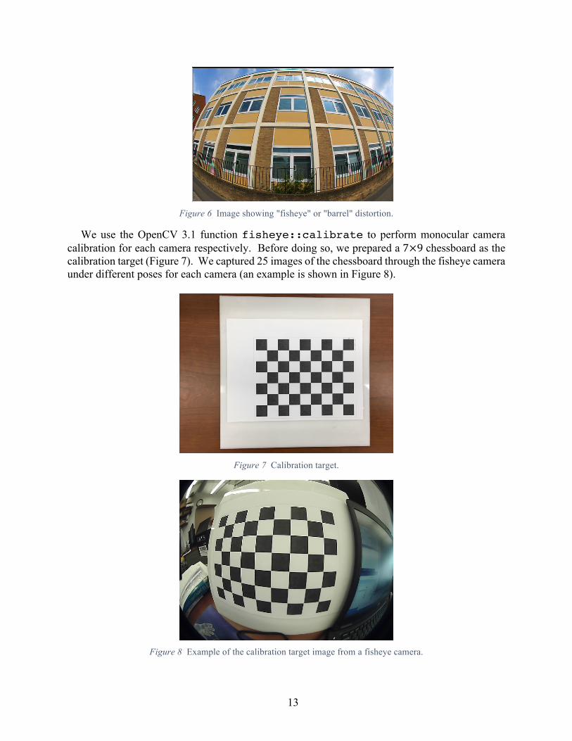
There are two different kinds of geometric distortion: radial distortion and tangential distortion. The former is related to the shape of a lens while the latter arises from the assembly process of the camera [10]. Radial Distortion is very obvious in images captured by fisheye cameras (such as the one we use to maximize field of view), especially for the pixels near the edges of the image. Thus the phenomenon caused by radial distortion is called “fisheye effect” or “barrel effect” (Figure 6). Compared to the effect of radial distortion, tangential distortion is usually negligible, and we ignore it in our implementation.
Within the implementation of fisheye model camera calibration of OpenCV, the distortion coefficient vector D has four parameters (whereas three are normally only required, due to the fisheye lens we add a forth),
𝐷 =
𝑘3𝑘4𝑘5𝑘6
and the actual coordinates (𝑥8, 𝑦8) of the 2D points in the image will be scaled according to the following equations:
𝑥8 = 𝑥(1 + 𝑘3𝑟4 + 𝑘4𝑟6 + 𝑘5𝑟< + 𝑘6𝑟=) 𝑦8 = 𝑦(1 + 𝑘3𝑟4 + 𝑘4𝑟6 + 𝑘5𝑟< + 𝑘6𝑟=)
where 𝑟 = (𝑥 − 𝑥()4 + (𝑦 − 𝑦()4.
13
Figure 6 Image showing "fisheye" or "barrel" distortion.
We use the OpenCV 3.1 function fisheye::calibrate to perform monocular camera calibration for each camera respectively. Before doing so, we prepared a 7×9 chessboard as the calibration target (Figure 7). We captured 25 images of the chessboard through the fisheye camera under different poses for each camera (an example is shown in Figure 8).
Figure 7 Calibration target.
Figure 8 Example of the calibration target image from a fisheye camera.

14
2.2.2 Stereo Calibration
Stereo calibration is the process of calculating the extrinsic parameters. The geometric relation between the two cameras in 3D space can be decomposed into a rotation and a translation (see Figure 9).
Figure 9 Geometric relation between the two cameras in 3D space.
Therefore, all the extrinsic parameters are stored in a rotation matrix R and a translation vector T, based on intrinsic matrices and distortion vectors of the two cameras. For a certain 3D point p, the relation between its coordinates with reference to left camera and right camera is
𝑋B𝑌B𝑍B
= 𝑅𝑋D𝑌D𝑍E
+ 𝑇
We use the OpenCV 3.1 function fisheye::stereoCalibrate to perform stereo
calibration for the binocular system. We captured 25 image pairs with the 7×9 checkboard as the calibration target (example shown in Figure 10).
Figure 10 Example of stereo images for calibration of the binocular system.

15
2.2.3 Stereo Rectification
With R and T computed, as well as K and D, calibrated from each monocular camera according to epipolar geometry, now we can confine the search space to be a line in the image for matching points in both images. If the two cameras are aligned to be parallel, the search space can be further simplified to a one-dimensional line, i.e., a horizontal line parallel to the baseline between the two cameras. Although this perfect camera alignment is impractical to maintain, stereo rectification is an alternative way to achieve that alignment.
There are many different ways to do stereo rectification, but all of them ensure that epipolar lines are parallel to the horizontal axis and corresponding points have the same vertical coordinates. In practice, we need to find two rotation matrices R1 and R2, which would rotate the two cameras to be coplanar.
We use the OpenCV function fisheye::stereoRectify to perform stereo rectification for the binocular system, using the two intrinsic matrices K1, K2, the two distortion vectors D1, D2 and extrinsic parameters R and T as input parameters. This yields two rotation matrix R1 and R2, two new projection matrices P1 and P2, and a disparity-to-depth matrix Q.
Since the two cameras are in fixed adjustment and the geometric relationship between them is also fixed, the intrinsic parameters (K1, K2, D1, and D2) and extrinsic parameters (R, T, R1 and R2) of both cameras are fixed, as are the projection matrices (P1 and P2) and the disparity-to-depth matrix Q. Thus, we only need to do the calibration and rectification once, as long as we neither change cameras nor their relative position and orientation. We store all the intrinsic parameters in a file named intrinsics.yml and all other parameters in a file named extrinsics.yml.
The camera calibration and rectification process follows the work flow in Figure 11.
Figure 11 Camera calibration and rectification work flow.
2.3 Target Detection and Tracking
Target detection and tracking constitute the core part of the PalmSight computer vision application, and represent two distinct modes of operation. The program is in detection mode until

16
the object is located and then switches to tracking mode after the target is successfully detected. If the target is lost in tracking mode, the program will switch modes back to detect the target again.
We have initially used a Pepsi-can, with its distinct red, white, and blue logo, as the preselected target. Both detection and tracking are performed on the unprocessed images captured by the right-hand camera in the stereo pair.
2.3.1 Detection
There are so many different methods for object detection [11] [12], such as Harr-Cascade [13], histogram-of-gradient/support-vector-machine (HoG-SVM) [14], and even some deep learning approaches. The Harr-Cascade method is famous for its application on face and eye detection while the HoG-SVM method is very effective in pedestrian detection. Both of them have been included in OpenCV. Since HoG-SVM is better at detecting objects with features mainly along edges, it is more suitable for our application. We take advantage of the cv::HOGDescriptor struct in the object detection module and cv::ml::SVM in the machine learning module of OpenCV.
The model for Pepsi-can detection is acquired as the following four steps: (1) We collect a set of positive samples (image patch with Pepsi-can) and negative samples (image patch without Pepsi-can). We choose to include many negative samples in the same region where we will test the performance of detection when the Pepsi-can doesn’t appear, and generate random bounding boxes to get the negative samples. (2) We extract HoG features for all those samples and set the sample labels of positive samples to be 1 while those of negative samples to be −1. Then we train all these data by linear SVM and save the generated parameters. (3) We run the initial detector on all the negative pictures and capture false positives (called hard negatives). (4) We add all those false positives to the existing negative sample set and retrain the detector. This step is called hard negative mining. The work flow is shown in Figure 12.
Figure 12 Model training work flow.

17
After the model is trained, we save all the parameters into a xml file, which can be read by the OpenCV function setSVMDetector.
The detection is performed as following: (1) We read the model parameters into the detector. (2) We perform multi-scale detection and obtain a list of results. Then we sort these detection result by their confidence from high to low. We treat the detection result with the highest confidence as the initial detection. (3) We compute the overlapping area between the initial detection with all other detection result and keep those detection results that have an overlapping area with the initial detection above a certain threshold. (4) The final detection result is then obtained by computing a minimum bounding box that contains the initial detection and all the other remaining detection results. This step is called non-maximum suppression.
In order to improve detection accuracy and decrease the false positive rate, we introduce two optional approaches to check the detection result. One is to check whether the similarity between the color histogram of the detection result and the average color histogram of all the positive templates is above a certain threshold. The other is to check whether the featured color ratio (in this case, blue) of the detection result is above a certain threshold. The entire detection work flow is shown in Figure 13.
Figure 13 Detection workflow in PalmSight.

18
Although we have had considerable success with our Pepsi-can detector, it currently is not reliable enough for the initial experiment described in Sections 1.1 and 3.2, due to the trade-off between the false positive rate and false negative rate. So in order to not affect the subsequent steps discussed below, we have for now resorted to printing a small 3×3 chessboard pattern as the detection target and modifying the built-in OpenCV function findChessboardCorners to acquire the bounding box of it. For the sake of the initial experiment, we are simply attaching the chessboard pattern to whatever object we wish to establish as the target.
2.3.2 Tracking
In most circumstances, object tracking is less time-consuming than object detection. So once the target is detected, we use it as a template and switch to tracking mode immediately. There are many different tracking methods to choose, from the classic Lucas-Kanade template tracking [15] to the state-of-art correlation filter based tracking methods [16]. Here, we choose to use an image alignment method using enhanced correlation coefficient maximization (ECC tracker), which has been written into OpenCV (findTransformECC). It is similar to some well-known variants of the Lucas-Kanade alignment method that take lighting changes into account, but has been reported to demonstrate superior performance [17]. The function findTransformECC estimates the optimum transformation with respect to ECC criterion
𝑤𝑎𝑟𝑝𝑀𝑎𝑡𝑟𝑖𝑥 = 𝑎𝑟𝑔maxR
𝐸𝐶𝐶(𝑡𝑒𝑚𝑝𝑙𝑎𝑡𝑒𝐼𝑚𝑎𝑔𝑒 𝑥, 𝑦 , 𝑖𝑛𝑝𝑢𝑡𝐼𝑚𝑎𝑔𝑒(𝑥8, 𝑦′))
where
𝑥′𝑦′ = 𝑊
𝑥𝑦1
During the tracking phase, we first estimate the warp based on a initial warp, which is a pure translation, and then compute the new bounding box and update the template. When any of the following situations occur, the program determines that the target is lost and switches back to detection mode.
• correlation output of function findTransformECC is below a certain threshold • estimated new bounding box crosses the boundary of camera view • width-to-height ratio of the estimated new bounding box does not lie within a certain range
2.4 Depth perception
By taking advantage of stereo vision, we can acquire depth information based on the disparity map. There are two categories of techniques to solve the correspondence problem and build a disparity map. One category includes local algorithms such as block matching and semi-global block matching [18], both of which have been included in OpenCV. The other category includes global optimization algorithms such as Graph Cut [19] and Belief Propagation [20]. Compared to local algorithms, methods in this category achieve better performance, since they not only focus on the quantified similarity, but also attempt to minimize the penalty caused by unsmoothness of the disparity solution. However, these methods require greater computation time.

19
2.4.1 Generate undistorted rectified image pairs
As mentioned above, for undistorted and rectified stereo image pairs, the search space could be confined to corresponding horizontal lines on image. So we would like to compute undistorted rectified image pairs first and then perform correspondence algorithm on them instead of on the original image pairs captured by the fisheye cameras. Based on all the camera intrinsic and extrinsic parameters, we use the OpenCV function fisheye::initUndistorRectifyMap to generate two mapping functions for x and y. Then the undistorted rectified image pairs can be generated according to the following relation:
𝑑𝑠t 𝑥, 𝑦 = 𝑠𝑟𝑐(𝑚𝑎𝑝$ 𝑥, 𝑦 ,𝑚𝑎𝑝)(𝑥, 𝑦))
where src is the original image and dst is the undistorted rectified image. Sample original image pairs and the generated undistorted rectified image pairs are shown in Figure 14.
Figure 14 Original (top) and undistorted rectified (bottom) image pairs

20
2.4.2 Generate disparity map
In order to achieve real-time performance in our application, we choose the naïve block-matching algorithm. There are several metrics we can use to quantify similarity, such as sum of squared differences (SSD), normalized cross-correlation (NCC) and sum of absolute differences (SAD). The implementation of the block matching algorithm in OpenCV uses SAD, which is inherently faster than the other two. The algorithm has two important parameters: block size and disparity search range. Block size is the linear size of the blocks compared by the algorithm. Larger block size implies smoother, though less accurate disparity map. Smaller block size gives more detailed disparity map, but there is a higher chance for the algorithm to find an incorrect correspondence. For each pixel, the algorithm will try to find the best disparity within the disparity search range along the corresponding epipolar line.
Since we use a local method to solve the correspondence problem, the outcome disparity map is not likely to be smooth. Therefore, we apply a disparity map filter based on weighted least squares so as to get a smoothed version. An example of such a generated disparity map compared to the corresponding undistorted rectified image from the right camera is shown in Figure 15.
Figure 15 Depth map (left) and one image from the corresponding stereo images pair (right).
2.4.3 Compute depth within interest area
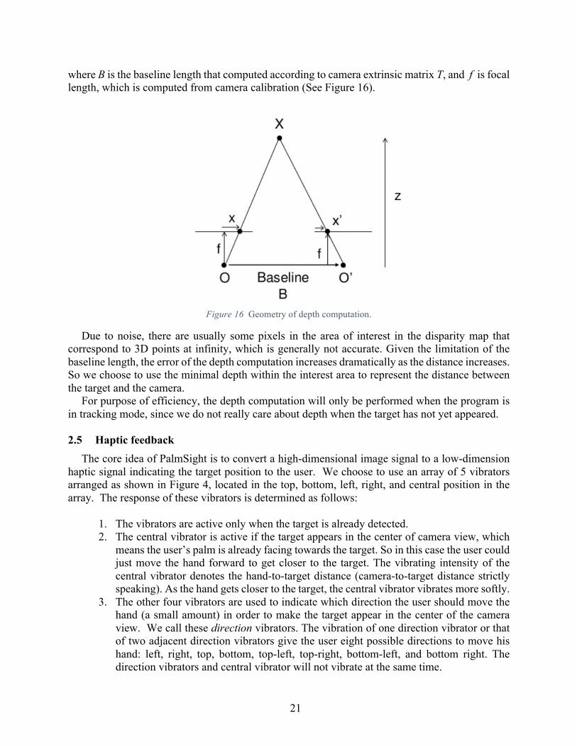
In practice, we are only interested in perceiving the depth of the target, not the other objects in the image. So we need to create a corresponding target bounding box in the undistorted rectified image to determine the interest area. Using both the intrinsic and extrinsic parameters of the cameras, we can undistort the 4 vertices of the bounding box in the original image to get their counterparts in the undistorted rectified images, using the OpenCV function undistortPoints. Then we can compute the depth within the interest area according to the following formula:
𝑑𝑒𝑝𝑡ℎ =𝐵𝑓
𝑑𝑖𝑠𝑝𝑎𝑟𝑖𝑡𝑦
21
where B is the baseline length that computed according to camera extrinsic matrix T, and f is focal length, which is computed from camera calibration (See Figure 16).
Figure 16 Geometry of depth computation.
Due to noise, there are usually some pixels in the area of interest in the disparity map that correspond to 3D points at infinity, which is generally not accurate. Given the limitation of the baseline length, the error of the depth computation increases dramatically as the distance increases. So we choose to use the minimal depth within the interest area to represent the distance between the target and the camera.
For purpose of efficiency, the depth computation will only be performed when the program is in tracking mode, since we do not really care about depth when the target has not yet appeared.
2.5 Haptic feedback
The core idea of PalmSight is to convert a high-dimensional image signal to a low-dimension haptic signal indicating the target position to the user. We choose to use an array of 5 vibrators arranged as shown in Figure 4, located in the top, bottom, left, right, and central position in the array. The response of these vibrators is determined as follows:
1. The vibrators are active only when the target is already detected. 2. The central vibrator is active if the target appears in the center of camera view, which
means the user’s palm is already facing towards the target. So in this case the user could just move the hand forward to get closer to the target. The vibrating intensity of the central vibrator denotes the hand-to-target distance (camera-to-target distance strictly speaking). As the hand gets closer to the target, the central vibrator vibrates more softly.
3. The other four vibrators are used to indicate which direction the user should move the hand (a small amount) in order to make the target appear in the center of the camera view. We call these direction vibrators. The vibration of one direction vibrator or that of two adjacent direction vibrators give the user eight possible directions to move his hand: left, right, top, bottom, top-left, top-right, bottom-left, and bottom right. The direction vibrators and central vibrator will not vibrate at the same time.

22
In the following sections, we will discuss further how these feedback signals are generated, transmitted to the electronics hardware, and finally used to drive the vibrators.
2.5.1 Generating the haptics feedback signal
Within the image from one of the cameras (the right camera), we use the central point of the target bounding box to represent the target position relative to the line of sight extending outward orthogonal to the user’s palm. As shown in Figure 17, the camera image is divided into 9 regions, according to a grid defined by a central region occupying 20% of both the horizontal (H) and vertical (V) axes. The haptic feedback command is generated according to which region contains the central point of target bounding box.
When the central point of the target bounding box lies in the center area, a specific “center”
command will be generated according to the current target depth. We divide the target depth into 4 different ranges:
• > 45 cm • 25-45 cm • 15-25 cm • 7-15 cm
So there are four different “center” command, depending on depth. When the target depth is less then 7 cm, a “grab” command is triggered, all the five vibrators vibrate, indicating that the target is close enough to grab. If the center of the bounding box lies in any of the other region, the corresponding direction vibrator(s) are activated, indicating that the target is off center and the user should move in that direction.
0.2W
H
W
0.2H
Figure 17 Regions of right camera image used to determine haptic feedback. W
23
2.5.2 Communication between laptop and vibrators
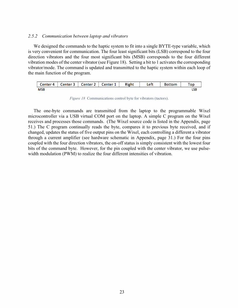
We designed the commands to the haptic system to fit into a single BYTE-type variable, which is very convenient for communication. The four least significant bits (LSB) correspond to the four direction vibrators and the four most significant bits (MSB) corresponds to the four different vibration modes of the center vibrator (see Figure 18). Setting a bit to 1 activates the corresponding vibrator/mode. The command is updated and transmitted to the haptic system within each loop of the main function of the program.
The one-byte commands are transmitted from the laptop to the programmable Wixel
microcontroller via a USB virtual COM port on the laptop. A simple C program on the Wixel receives and processes those commands. (The Wixel source code is listed in the Appendix, page 51.) The C program continually reads the byte, compares it to previous byte received, and if changed, updates the status of five output pins on the Wixel, each controlling a different a vibrator through a current amplifier (see hardware schematic in Appendix, page 31.) For the four pins coupled with the four direction vibrators, the on-off status is simply consistent with the lowest four bits of the command byte. However, for the pin coupled with the center vibrator, we use pulse-width modulation (PWM) to realize the four different intensities of vibration.
Figure 18 Communications control byte for vibrators (tactors).

24
2.6 Program Work flow The core work flow of the PalmSight program is shown in Figure 19.
Figure 19 Core work flow of the PalmSight program
First, the program performs initializations, including opening the camera and communications (COM) ports, reading in camera parameters, and computing the undistort rectify map, etc. After that, the program enters the main loop, where first it updates the image pairs captured by the cameras, as well as the corresponding undistorted rectified image pair. If the target object is already detected, the program proceeds to tracking; otherwise it continues to attempt detection.

25
The detection status may turn to false in the tracking phase due to a failure in tracking, in which case it checks the detection status again to see whether the target object has just been detected. If so, the program updates the tracking template, generates the depth map, and computes depth information for the target.
No matter whether target object is detected or not, the program displays the original captured image pairs and corresponding undistorted rectified image pairs. But it only displays the depth map if target is currently detected, since actually we cannot otherwise compute depth information for the target. Finally, the resulting command for haptic feedback system is updated and sent to the Wixel at the end of each loop.

26
3 Experimental Protocols and Results
3.1 Tactor Array Discrimination In the design of the PalmSight prototype, an experiment was conducted to determine the best
tactor positioning on the back of the hand. As shown in Figure 20, Four different configurations of 4-vibrator, and 5-vibrator arrays were established and placed on subjects’ hands using glue-dots at locations marked with a pen using paper guides (B). Subjects were asked to distinguish between vibrations of the individual vibrators, by pressing letters on the computer keyboard corresponding to labels on the individual vibrators (C). Subjects were asked to identify vibrators in randomized trials of 32 vibrations (4-vibrator) and 40 vibrations (5-vibrator) containing 8 repeats of each vibrator vibration within each trial.
Figure 20 Experiment to determine optimal placement of vibrators.
The results indicate a seemingly consistent ability to distinguish between and correctly identify the different vibrator vibrations. Of the sum total 286 vibrations experienced by the two participating subjects, only 6 vibrations were incorrectly identified. 3.2 Evaluation of PalmSight for reaching to target
The planned experiment that will evaluate the PalmSight prototype has already been described in Section 1.1. Generally speaking, we will test the ability of blindfolded subjects to find an object in a constrained workspace, and we will record the experiment data such as success rate and time to success. The experimental protocol is described in detail in the appendix at page 52, and has been approved by the Institutional Review Board (IRB).

27
4 Discussion and Conclusion
The work presented in this paper entails the development of a new form of assistive technology for the blind and visually impaired. Based on a previous approach called FingerSight, the new approach places stereo cameras in the palm of the operator to detect and locate objects that the operator would want to pick up with that hand. Modern computer vision techniques have rapidly improved such that object identification and 3D localization by stereo depth determination are quite capable of useful operation given instruction from the user as to what object is desired. This information can be used to control vibrators on the back of the user’s hand to direct the hand to find and grasp the object. We have constructed an initial PalmSight prototype, and designed an experiment in its operation. With recent IRB approval, this experiment is just now getting underway with subjects from the Psychology Department at CMU. Among other things, the experiment will compare PalmSight to an approach analogous to using an existing stand-alone cell-phone in one hand to guide the other hand to find and grasp the target object. Smart-phones, after all, come equipped already with cameras and vibrators, so this part of the experiment will explore potential competition for PalmSight from the existing technology.
We expect to learn a great deal from this initial experiment, and to be able to improve the operation and utility of PalmSight technology based on these results. The modular nature of computer vision algorithms, in particular, within the OpenCV framework, as well as the continual updates from ongoing research within the research community, will facilitate this further development. We further expect to benefit from miniaturization of camera technology in future iterations, custom design using rapid prototyping, and the introduction of wireless technology, with the likely switch from laptop computer to tablet or smart-phone for the computational platform. We believe, however, that the benefits of keeping the hand-mounted cameras and vibrators, rather than simply having the operator use an existing stand-alone smart-phone, will be validated by our initial experiment. A possible solution may actually be a combination of smart-phone and hand mounted camera/vibrator system, connected wirelessly, with the smart-phone supplying computational power and possibly an extra, detached camera.
One area that we are actively exploring is the use of PalmSight to direct the use of a tool held in the same hand. Thus, rather than directing the user to pick up an object, PalmSight could direct the user to bring the tip of a fork to be in contact with a particular food item on a plate, or to insert a key into a lock in a door. The tools themselves could be equipped with cameras to facilitate this general approach, an extension of ongoing research in our lab that we call ProbeSight, in which surgical tools are equipped with cameras to navigate relative to the exterior of the patient [21].
Another potential extension of PalmSight and FingerSight is the incorporation of Simultaneous Localization and Mapping (SLAM) into its operation. SLAM is a technique by which robotic devices can explore their environment with cameras and other sensors, incrementally creating a map and an estimate of the robot’s location on that map as the robot moves [22]. A recent research effort by Google in the development of their Tango platform was based on a special Android phone with multiple cameras, structured light, and inertial and magnetic sensors, which can construct, and continually update, a map of the visible 3D environment. Such systems as this, once commercially available, could be adapted to use our camera and sensor data, so that the operator could create an external spatial memory, within which desired objects can be identified and remembered. Thus the user will be able to say, “Where did I leave my car keys,” and be directed by the vibrator array to the correct room and table, and finally, to reach out and pick up the keys.

28
The spatial memory could also be embedded in a larger context provided by standard GPS and cellphone location data.
We believe our general approach to assistive technology is both important in its potential impact and timely in terms of the confluence of current technologies in portable computing and computer vision. The concept of enlisting the aid of powerful real-time computation in the analysis of the visual world, for those who lack the biological equivalent, holds great promise in the very near term, to make a major step forward improving the quality of life for these individuals.

29
5 References
[1] D. Blackwell, J. Lucas and T. Clarke...., "Summary health statistics for U.S. adults:
National Health Interview Survey, 2012," National Center for Health Statistics, vol. 10, p. 260, 2014.
[2] E. R. Strelow and D. H. Warren,, Electronic Spatial Sensing for the Blind., Martinus Nijhoff, 1985.
[3] S. D. Novich and D. M. Eagleman, "Using space and time to encode vibrotactile information: toward an estimate of the skin’s achievable throughput," Experimental Brain Research, vol. 233, no. 10, pp. 2777-2788.
[4] C. Lenay, O. Gapenne, S. Hanneton and C. Marque, Sensory substitution: Limits and perspectives Touching For Knowing: Cognitive Psychology Of Haptic Manual Perception, Amsterdam: John Benjamins, 2003, p. 275–292.
[5] J. Loomis, Sensory replacement and sensory substitution: Overview and prospects for the future Converging Technologies for Improving Human Performance: Nanotechnology, Biotechnology, Information Technology and Cognitive Science, Dordrecht: Kluwer, 2003, p. 213–223.
[6] F. Maingreaud, E. E. Pissaloux, R. Velazquez, F. Gaunet and M. Haf, "A dynamic tactile map as a tool for space organization perception: Application to the design of an electronic travel aid for visually impaired and blind people," Proc. IEEE Eng. Med. Biol. Soc., pp. 6912-6915, Jan. 2005.
[7] P. B.-Y. Rita and M. E. Tyler, "Tongue man-machine interface," Proc. Med. Meets Virtual Reality, 2000.
[8] S. Horvath, J. Galeotti, B. Wu, R. Klatzky, M. Siegel and G. Stetten, "FingerSight: Fingertip Haptic Sensing of the Visual Environment, ,, ,," IEEE Journal of Translational Engineering in Health and Medicine, March 2014.
[9] G. Stetten and B. Klatzky, "Fingertip Visual Haptic Sensor Controller". Patent 9024874, 5 May 2015.
[10] D. C. Brown, "Decentering distortion of lenses," Photometric Engineering, vol. 32, no. 3, pp. 444-462, 1966.
[11] A. Kaehler and G. Bradski, Learning OpenCV 3: Computer Vision in C++ with the OpenCV Library, O'Reilly.
[12] R. Szeliski, Computer Vision: Algorithms and Applications, London: Springer, 2011. [13] P. Viola and M. Jones, "Rapid object detection using a boosted cascade of simple
features," in Computer Vision and Pattern Recognition, 2001. [14] N. Dalal and B. Triggs, "Histograms of oriented gradients for human detection," in
Computer Vision and Pattern Recognition, 2005. [15] S. Baker and I. Matthews, "Lucas-kanade 20 years on: A unifying framework,"
International journal of computer vision, vol. 56, no. 3, pp. 221-255, 2004. [16] D. Bolme, J. R. Beveridge and B. A. Draper, "Visual object tracking using adaptive
correlation filters," in Computer Vision and Pattern Recognition, 2010.

30
[17] G. Evangelidis and E. Psarakis, "Parametric Image Alignment Using Enhanced Correlation Coefficient Maximization," IEEE Transactions on Pattern Analysis and Machine Intelligence, no. 10, pp. 1858 - 1865, Oct. 2008.
[18] H. Hirschmuller, "Stereo processing by semiglobal matching and mutual information," IEEE Transactions on pattern analysis and machine intelligence, vol. 30, no. 2, pp. 328-341, 2008.
[19] Y. Boykov, O. Veksler and R. Zabih, "Fast approximate energy minimization via graph cuts," IEEE Transactions on pattern analysis and machine intelligence, vol. 23, no. 11, pp. 1222-1239, 2001.
[20] P. F. Felzenszwalb and D. P. Huttenlocher, "Efficient belief propagation for early vision," International Journal of Computer Vision, vol. 70, no. 1, pp. 41-54, 2006.
[21] J. Wang, V. Shivaprabhu, J. Galeotti, S. Horvath and G. Stetten, "Towards video guidance for ultrasound, using a prior high-resolution 3D surface map of the external anatomy," Lecture Notes in Computer Science, vol. 8678, pp. pp 51-59, 2014.
[22] M. Dissanayake, "A solution to the simultaneous localization and map building (SLAM) problem," IEEE Transactions on Robotics and Automation, vol. 17, no. 3, p. 229 – 241, June 2001.

31
6 Appendices
6.1 Hardware Schematic
Figure 21 Schematic of hardware interface for vibrator activation (note optional hardware oscillator for 50% duty
cycle, not used when software controls duty cycle).

32
6.2 Laptop Software 6.2.1 palmsight.h
/* palmsight.h */ /* Zhixuan Yu */ /* 12/5/2016 */ #include <iostream> #include <fstream> #include <windows.h> #include <opencv2/core/utility.hpp> #include <opencv2/highgui/highgui.hpp> #include <opencv2/imgproc/imgproc.hpp> #include <opencv2/ml/ml.hpp> #include <opencv2/objdetect/objdetect.hpp> #include <opencv2/video/video.hpp> #include <opencv2/video/tracking.hpp> #include <opencv2/calib3d/calib3d.hpp> #include "opencv2/ximgproc/disparity_filter.hpp" using namespace std; using namespace cv; using namespace ml; #define TOP 0x01 #define BOTTOM 0x02 #define LEFT 0x04 #define RIGHT 0x08 #define CENTER1 0x10 #define CENTER2 0x20 #define CENTER3 0x40 #define CENTER4 0x80 #define LEFT_CAMERA true #define RIGTH_CAMERA false class palmsight { public: enum { STEREO_BM = 0, STEREO_SGBM = 1, STEREO_HH = 2, STEREO_VAR = 3, STEREO_3WAY = 4 }; public: VideoCapture leftCamera, rightCamera; Mat leftView, rightView, bothView; // original Mat leftView_gray, rightView_gray; Mat leftImg, rightImg, bothImg; // undistorted & rectified Mat leftImg_gray, rightImg_gray; Mat leftImg_grays, rightImg_grays, leftImg_s, rightImg_s; // scaled (for block matching purpose) //Mat leftImg, rightImg; Size viewsize; Mat map11, map12, map21, map22; VideoWriter binocularVideo, depthVideo; FILE *logfile; string info; bool isDetected; bool isTracking; bool isCamerasOpen; bool useflip; bool usefisheye; bool useBuzzer; bool useColor;

33
bool useHist; bool useLabel; bool recordVideo; bool isExperiment; int alg; int SADWindowSize; int numberOfDisparities; double lambda; double sigma; float scale_for_match = 0.5; Ptr<StereoBM> bm; Ptr<StereoSGBM> sgbm; Ptr<StereoMatcher> right_matcher; Ptr<ximgproc::DisparityWLSFilter> wls_filter; Mat disp, disp_right, filtered_disp; Mat visualized_disp, visualized_filtered_disp, color_visualized_filtered_disp; Mat depth; float targetDepth; HOGDescriptor hog; Mat leftTemplate, rightTemplate; Rect leftBox, rightBox; // target bounding box in original image pairs Rect leftBox_u, rightBox_u; // target bounding box in undistort-rectified image pairs int histSize = 16; Mat BlueHist[50]; Mat GreenHist[50]; Mat RedHist[50]; double f; // focal length double B; // baseline length Mat K, D, R, P; // corresponding info for dominant camera // not useful now Mat warp; Mat_<Point> pts; public: //constructor palmsight(int index1, int index2); //one-time functions void getViewSize(); void setDetector(char *detectorSavePath); void iniStereoMatchObject(int SADWindowSize = 9, int numberOfDisparities = 64, double lambda = 8000, double sigma = 1.5); bool generateUndistortRectifyMap(bool isLeft, string intrinsic_filename, string extrinsic_filename); //loop calling functions void updateViews(); void generateUndistortRectifyStereoImagePairs(); bool detect(bool isLeft, float thr_color_ratio = 0.06, float thr_hist_ratio = 0.3); bool detectLabel(bool isLeft); bool track(bool isLeft = false, float thr_corr = 0.8, float thr_hw_ratio_max = 1.8, float thr_hw_ratio_min = 1.0); bool track2(bool isLeft = false, float thr_corr = 0.8, float thr_hw_ratio_max = 1.8, float thr_hw_ratio_min = 1.0); void generateDepthInfo(float scale = 1.0, int numberOfDisparities = 64); void display(); BYTE generateCommand(float ratioH = 0.1, float ratioW = 0.1, float grab = 7); //optional functions double extractFeaturedColorRatio(bool isLeft); void calculatehist(); double comparehist(bool isLeft); void videoRecord(); };

34
int handleError(int status, const char* func_nae, const char* err_msg, const char* file_name, int line, void* userdata);

35
6.2.2 palmsight.cpp
/* palmsight.cpp */ /* Zhixuan Yu */ /* 12/5/2016 */ #include "palmsight.h" /* Constructor */ palmsight::palmsight(int index1, int index2) : isDetected(0) , isTracking(0) , useflip(1) , usefisheye(1) , useBuzzer(0) , useColor(0) , useHist(0) , useLabel(1) , recordVideo(0) , isExperiment(0) , alg(STEREO_BM) , leftCamera(index1) , rightCamera(index2) , hog(Size(64, 96), Size(16, 16), Size(8, 8), Size(8, 8), 9) { bool left = leftCamera.isOpened(); bool right = rightCamera.isOpened(); if (!left) cout << "Failed to open left camera." << endl; if (!right) cout << "Failed to open right camera." << endl; isCamerasOpen = left && right; } /* acquire the size of image captured by camera */ void palmsight::getViewSize() { leftCamera >> leftView; viewsize = leftView.size(); } /* function to load pepsi detector */ void palmsight::setDetector(char *detectorSavePath) { vector<float> detector; ifstream fileIn(detectorSavePath, ios::in); float val = 0.0f; while (!fileIn.eof()) { fileIn >> val; detector.push_back(val); } fileIn.close(); hog.setSVMDetector(detector); } /* function to initiate block matcher object(bm / sgbm) */ void palmsight::iniStereoMatchObject(int SADWindowSize, int numberOfDisparities, double lambda, double sigma) { Rect roi1, roi2; //Mat Q; bm = StereoBM::create(numberOfDisparities, SADWindowSize); sgbm = StereoSGBM::create(0, numberOfDisparities, SADWindowSize); if (alg == STEREO_BM) { wls_filter = ximgproc::createDisparityWLSFilter(bm); right_matcher = ximgproc::createRightMatcher(bm); } else{ wls_filter = ximgproc::createDisparityWLSFilter(sgbm);

36
right_matcher = ximgproc::createRightMatcher(sgbm); } wls_filter->setLambda(lambda); wls_filter->setSigmaColor(sigma); //numberOfDisparities = numberOfDisparities > 0 ? numberOfDisparities : ((img_size.width / 8) + 15) & -16; bm->setROI1(roi1); bm->setROI2(roi2); bm->setPreFilterCap(31); bm->setBlockSize(SADWindowSize > 0 ? SADWindowSize : 9); bm->setMinDisparity(0); bm->setNumDisparities(numberOfDisparities); bm->setTextureThreshold(10); bm->setUniquenessRatio(15); bm->setSpeckleWindowSize(100); bm->setSpeckleRange(32); bm->setDisp12MaxDiff(1); sgbm->setPreFilterCap(63); int sgbmWinSize = SADWindowSize > 0 ? SADWindowSize : 3; sgbm->setBlockSize(sgbmWinSize); int cn = leftView.channels(); sgbm->setP1(8 * cn*sgbmWinSize*sgbmWinSize); sgbm->setP2(32 * cn*sgbmWinSize*sgbmWinSize); sgbm->setMinDisparity(0); sgbm->setNumDisparities(numberOfDisparities); sgbm->setUniquenessRatio(10); sgbm->setSpeckleWindowSize(100); sgbm->setSpeckleRange(32); sgbm->setDisp12MaxDiff(1); if (alg == STEREO_HH) sgbm->setMode(StereoSGBM::MODE_HH); else if (alg == STEREO_SGBM) sgbm->setMode(StereoSGBM::MODE_SGBM); else if (alg == STEREO_3WAY) sgbm->setMode(StereoSGBM::MODE_SGBM_3WAY); } bool palmsight::generateUndistortRectifyMap(bool isLeft, string intrinsic_filename, string extrinsic_filename) { /* Read intrinsic file */ FileStorage fs(intrinsic_filename, FileStorage::READ); if (!fs.isOpened()) { printf("Failed to open file %s\n", intrinsic_filename.c_str()); return false; } Mat M1, D1, M2, D2; fs["M1"] >> M1; fs["D1"] >> D1; fs["M2"] >> M2; fs["D2"] >> D2; // get average focal length for later use in generating depth info f = (M1.at<double>(0, 0) + M1.at<double>(1, 1) + M2.at<double>(0, 0) + M2.at<double>(1, 1)) / 4; //M1 *= scale; //M2 *= scale; /* Read extrinsic file */ fs.open(extrinsic_filename, FileStorage::READ); if (!fs.isOpened()) { printf("Failed to open file %s\n", extrinsic_filename.c_str()); return false; }

37
Mat R, T, R1, P1, R2, P2, Q; fs["R"] >> R; fs["T"] >> T; fs["R1"] >> R1; fs["R2"] >> R2; fs["P1"] >> P1; fs["P2"] >> P2; fs["Q"] >> Q; // get baseline length for later use in generating depth info B = T.at<double>(0); /* Generate maps */ if (!usefisheye) { initUndistortRectifyMap(M1, D1, R1, P1, viewsize, CV_16SC2, map11, map12); initUndistortRectifyMap(M2, D2, R2, P2, viewsize, CV_16SC2, map21, map22); } else { fisheye::initUndistortRectifyMap(M1, D1, R1, P1, viewsize, CV_16SC2, map11, map12); fisheye::initUndistortRectifyMap(M2, D2, R2, P2, viewsize, CV_16SC2, map21, map22); } // store info of dominant camera into member variables if (isLeft) { K = M1; D = D1; R = R1; P = P1; } else { K = M2; D = D2; R = R2; P = P2; } return true; } // Update camera views void palmsight::updateViews() { leftCamera >> leftView; rightCamera >> rightView; if (useflip) { flip(leftView, leftView, 0); flip(rightView, rightView, 0); } // get grayscale version for later use cvtColor(leftView, leftView_gray, CV_BGR2GRAY); cvtColor(rightView, rightView_gray, CV_BGR2GRAY); } void palmsight::generateUndistortRectifyStereoImagePairs() { // get undistorted rectified camera images remap(leftView, leftImg, map11, map12, INTER_LINEAR); remap(rightView, rightImg, map21, map22, INTER_LINEAR); // get grayscale version for later use cvtColor(leftImg, leftImg_gray, CV_BGR2GRAY); cvtColor(rightImg, rightImg_gray, CV_BGR2GRAY); // scale for stereo match procedure int method = scale_for_match < 1 ? INTER_AREA : INTER_CUBIC; if (alg == STEREO_BM) { resize(leftImg_gray, leftImg_grays, Size(), scale_for_match, scale_for_match, method); resize(rightImg_gray, rightImg_grays, Size(), scale_for_match, scale_for_match, method); } else { resize(leftImg, leftImg_s, Size(), scale_for_match, scale_for_match, method);

38
resize(rightImg, rightImg_s, Size(), scale_for_match, scale_for_match, method); } } bool palmsight::detect(bool isLeft, float thr_color_ratio, float thr_hist_ratio) { vector<Rect> found; vector<double> weight; Rect *boundingboxp; Mat img; if (isLeft) { img = leftImg_gray; boundingboxp = &leftBox; } else { img = rightImg_gray; boundingboxp = &rightBox; } //Multiscale detection hog.detectMultiScale(img, found, weight, 0, Size(8, 8), Size(0, 0), 1.42, 0.8); //Sort int targetNum = found.size(); int *index = new int[targetNum]; for (int i = 0; i < targetNum; i++) index[i] = i; sort(index, index + targetNum, [&weight](int i, int j) {return weight[i] > weight[j]; }); //Compute bounding box if (targetNum > 0) {//parameter //NMS int x01 = found[0].x; int x02 = found[0].x + found[0].width - 1; int y01 = found[0].y; int y02 = found[0].y + found[0].height - 1; double area0 = (x02 - x01 + 1) * (y02 - y01 + 1); int X1 = x01; int X2 = x02; int Y1 = y01; int Y2 = y02; int cnt = 0; for (int i = 1; i < targetNum; i++) { int xi1 = found[i].x; int yi1 = found[i].y; int xi2 = xi1 + found[i].width - 1; int yi2 = yi1 + found[i].height - 1; int xx1 = max(x01, xi1); int yy1 = max(y01, yi1); int xx2 = min(x02, xi2); int yy2 = min(y02, yi2); int w = max(0, xx2 - xx1 + 1); int h = max(0, yy2 - yy1 + 1); double inter = w * h; double areai = found[i].width * found[i].height; double o = inter / (area0 + areai - inter); if (o > 0.7) {//parameter X1 = min(X1, xi1); Y1 = min(Y1, yi1); X2 = max(X2, xi2); Y2 = max(Y2, yi2); cnt++; } } if (cnt > 0) {//parameter *boundingboxp = Rect(X1, Y1, X2 - X1 + 1, Y2 - Y1 + 1); bool color = true, hist = true; if (useColor) color = extractFeaturedColorRatio(isLeft) > thr_color_ratio;//parameter if (useHist) hist = comparehist(isLeft) > thr_hist_ratio;//parameter

39
return color&hist ; } } return false; } bool palmsight::detectLabel(bool isLeft) { Rect *boundingboxp; Mat img, img_gray; Mat *templateImage; if (isLeft) { //img = leftImg; img = leftView; img_gray = leftImg_gray; templateImage = &leftTemplate; boundingboxp = &leftBox; } else { //img = rightImg; img = rightView; img_gray = rightImg_gray; templateImage = &rightTemplate; boundingboxp = &rightBox; } vector<Point2f> pointBuf; int chessBoardFlags = CALIB_CB_ADAPTIVE_THRESH | CALIB_CB_NORMALIZE_IMAGE | CALIB_CB_FAST_CHECK; if ( findChessboardCorners(img, Size(3, 3), pointBuf, chessBoardFlags) ) { Point2f corner = pointBuf[0]; int xmin = corner.x; int xmax = xmin; int ymin = corner.y; int ymax = ymin; int w, h; for (int i = 1; i < 9; i++) { corner = pointBuf[i]; xmin = xmin < corner.x ? xmin : corner.x; xmax = xmax > corner.x ? xmax : corner.x; ymin = ymin < corner.y ? ymin : corner.y; ymax = ymax > corner.y ? ymax : corner.y; } w = round((xmax - xmin) * 2) + 1; h = round((ymax - ymin) * 2) + 1; xmin = round(2 * xmin - pointBuf[4].x); ymin = round(2 * ymin - pointBuf[4].y); *boundingboxp = Rect(xmin, ymin, w,h); // handling cross-boundary situation int Width = viewsize.width; int Height = viewsize.height; if (boundingboxp->x < 0) boundingboxp->x = 0; if (boundingboxp->y < 0) boundingboxp->y = 0; if (boundingboxp->x + boundingboxp->width > Width) boundingboxp->width = Width - boundingboxp->x; if (boundingboxp->y + boundingboxp->height > Height) boundingboxp->height = Height - boundingboxp->y; // new code : initialize warp after each successful detection //warp = (Mat_<float>(2, 3) << 1, 0, boundingboxp->x, 0, 1, boundingboxp->y); //*templateImage = img_gray(*boundingboxp).clone(); return true; } return false; } int handleError(int status, const char* func_nae, const char* err_msg, const char* file_name, int line, void* userdata) {
40
return 0; } bool palmsight::track(bool isLeft, float thr_corr, float thr_hw_ratio_max, float thr_hw_ratio_min) { double corr; int Width = viewsize.width; int Height = viewsize.height; Rect *boundingboxp, *boundingboxp_u; Mat templateImage, img; if (isLeft) { templateImage = leftTemplate; //img = leftImg_gray; img = leftView_gray; boundingboxp = &leftBox; boundingboxp_u = &leftBox_u; } else { templateImage = rightTemplate; //img = rightImg_gray; img = rightView_gray; boundingboxp = &rightBox; boundingboxp_u = &rightBox_u; } //Compute warp matrix based on initial warp(pure translation) Mat warp = (Mat_<float>(2, 3) << 1, 0, boundingboxp->x, 0, 1, boundingboxp->y); try { corr = findTransformECC(templateImage, img, warp, MOTION_AFFINE, TermCriteria(TermCriteria::COUNT + TermCriteria::EPS, 1000, 0.01)); } catch (Exception &e){ corr = -1; } //Handling low correlation situation if (corr < thr_corr) { if (!recordVideo && !isExperiment) cout << "Redetecting... since correlation is too small" << endl; return false; } //Compute bounding box, may use different strategy Mat v1 = warp * (Mat_<float>(3, 1) << 0, 0, 1); Mat v2 = warp * (Mat_<float>(3, 1) << 0, (boundingboxp->height - 1), 1); Mat v3 = warp * (Mat_<float>(3, 1) << (boundingboxp->width - 1), 0, 1); Mat v4 = warp * (Mat_<float>(3, 1) << (boundingboxp->width - 1), (boundingboxp->height - 1), 1); Mat P1 = (Mat_<float>(3, 1) << (v1.at<float>(0, 0) + v2.at<float>(0, 0)) / 2, (v1.at<float>(1, 0) + v3.at<float>(1, 0)) / 2, 1); Mat P2 = (Mat_<float>(3, 1) << (v3.at<float>(0, 0) + v4.at<float>(0, 0)) / 2, (v2.at<float>(1, 0) + v4.at<float>(1, 0)) / 2, 1); boundingboxp->x = (int)(P1.at<float>(0, 0) + 0.5);//Attention: must round to nearest integer, or error may cumulate. boundingboxp->y = (int)(P1.at<float>(1, 0) + 0.5);//Here we use "plus 0.5 and force convert to int" strategy to realize rounding boundingboxp->width = (int)(P2.at<float>(0, 0) - P1.at<float>(0, 0) + 0.5) + 1; boundingboxp->height = (int)(P2.at<float>(1, 0) - P1.at<float>(1, 0) + 0.5) + 1; //Compute bounding box for undistorted image Mat points(2, 1, CV_32FC2); Mat points_u(2, 1, CV_32FC2); points.at<Vec2f>(0)[0] = P1.at<float>(0); points.at<Vec2f>(0)[1] = P1.at<float>(1); points.at<Vec2f>(1)[0] = P2.at<float>(0); points.at<Vec2f>(1)[1] = P2.at<float>(1); undistortPoints(points, points_u, K, D, R, P); boundingboxp_u->x = (int)(points_u.at<Vec2f>(0)[0] + 0.5); boundingboxp_u->y = (int)(points_u.at<Vec2f>(0)[1] + 0.5); boundingboxp_u->width = (int)(points_u.at<Vec2f>(1)[0] - points_u.at<Vec2f>(0)[0] + 0.5) + 1; boundingboxp_u->height = (int)(points_u.at<Vec2f>(1)[1] - points_u.at<Vec2f>(0)[1] + 0.5) + 1;

41
//Handling cross boundary situation if (boundingboxp->x < 0) boundingboxp->x = 0; if (boundingboxp->y < 0) boundingboxp->y = 0; if (boundingboxp->x + boundingboxp->width > Width) boundingboxp->width = Width - boundingboxp->x; if (boundingboxp->y + boundingboxp->height > Height) boundingboxp->height = Height - boundingboxp->y; if (boundingboxp_u->x < 0) boundingboxp_u->x = 0; if (boundingboxp_u->y < 0) boundingboxp_u->y = 0; if (boundingboxp_u->x + boundingboxp_u->width > Width) boundingboxp_u->width = Width - boundingboxp_u->x; if (boundingboxp_u->y + boundingboxp_u->height > Height) boundingboxp_u->height = Height - boundingboxp_u->y; if (boundingboxp_u->width < 1 || boundingboxp_u->height < 1 || boundingboxp->width < 1 || boundingboxp->height < 1) { return false; } //Determine whether is close enough /* float Radio = ((float)boundingboxp->height * (float)boundingboxp->width) / ((float)Width * (float)Height); if (Radio > 0.9){ //cout << "\nYou hand is close enough to the pepsi can, just grap it!!!" << endl; return 1; }*/ //Handling distorted height-to-width radio situation float radio = (float)boundingboxp->height / (float)boundingboxp->width; //Attention: must convert to float before do division if ((radio > thr_hw_ratio_max || radio < thr_hw_ratio_min) /*&& (boundingboxp->height < 0.9*Height)*/) { if (!recordVideo && !isExperiment) cout << "Redetecting... since distorted height-to-width radio..." << endl; return false; } return true; } bool palmsight::track2(bool isLeft, float thr_corr, float thr_hw_ratio_max, float thr_hw_ratio_min) { double corr; Mat *templateImage, img; Rect *boundingboxp; if (isLeft) { templateImage = &leftTemplate; img = leftImg_gray; boundingboxp = &leftBox; } else { templateImage = &rightTemplate; img = rightImg_gray; boundingboxp = &rightBox; } //Compute polygon pts Mat v1 = warp * (Mat_<float>(3, 1) << 0, 0, 1); Mat v2 = warp * (Mat_<float>(3, 1) << 0, (boundingboxp->height - 1), 1); Mat v3 = warp * (Mat_<float>(3, 1) << (boundingboxp->width - 1), (boundingboxp->height - 1), 1); Mat v4 = warp * (Mat_<float>(3, 1) << (boundingboxp->width - 1), 0, 1); vector<Point> contour; contour.push_back(Point(v1.at<float>(0), v1.at<float>(1))); contour.push_back(Point(v2.at<float>(0), v2.at<float>(1))); contour.push_back(Point(v3.at<float>(0), v3.at<float>(1))); contour.push_back(Point(v4.at<float>(0), v4.at<float>(1))); pts = Mat(contour);
42
try { corr = findTransformECC(*templateImage, img, warp, MOTION_AFFINE, TermCriteria(TermCriteria::COUNT + TermCriteria::EPS, 1000, 0.01)); } catch (Exception &e){ corr = -1; } //Handling low correlation situation if (corr < thr_corr) { if (!recordVideo && !isExperiment) cout << "Redetecting... since correlation is too small" << endl; return false; } // update template warpAffine(img, *templateImage, warp, templateImage->size(), INTER_LINEAR | WARP_INVERSE_MAP, BORDER_CONSTANT); //imwrite("templateImge.jpg", *templateImage); return true; } void palmsight::generateDepthInfo(float scale, int numberOfDisparities) { // stereo match computation(Pay attention to the order of images!!!) if (alg == STEREO_BM) { bm->compute(rightImg_grays, leftImg_grays, disp); right_matcher->compute(leftImg_grays, rightImg_grays, disp_right); } else if (alg == STEREO_SGBM || alg == STEREO_HH || alg == STEREO_3WAY) { sgbm->compute(rightImg_s, leftImg_s, disp); right_matcher->compute(leftImg_s, rightImg_s, disp_right); } // post-process filtering wls_filter->filter(disp, rightImg, filtered_disp, disp_right);//left disp map, left view, filtered disp map, right disp map // compute camera-to-target distance divide(B * f * 16, filtered_disp, depth);//baseline length * focal length, multiplied by 16 to match filtered_disp that was scaled by 16 //Mat target = depth(rightBox); Mat target = depth(rightBox_u); Mat mask = (target > 0); double minVal; double maxVal; Point minLoc, maxLoc; minMaxLoc(target, &minVal, &maxVal, &minLoc, &maxLoc, mask); targetDepth = minVal*scale / 10.0;//convert from mm to cm // get visualized disparity map if (alg != STEREO_VAR) { disp.convertTo(visualized_disp, CV_8U, 255 / (numberOfDisparities*16.)); filtered_disp.convertTo(visualized_filtered_disp, CV_8U, 255 / (numberOfDisparities*16.)); } else { disp.convertTo(visualized_disp, CV_8U); filtered_disp.convertTo(visualized_filtered_disp, CV_8U); } } void palmsight::display() { Point tOrigin(leftView.cols / 2, 20); // put text and show original stereo pairs if (isDetected) rectangle(rightView, rightBox, CV_RGB(0, 255, 0), 3); putText(leftView, String("L"), tOrigin, 1, 1.5, Scalar(0, 255, 0), 1.5); putText(rightView, String("R"), tOrigin, 1, 1.5, Scalar(0, 255, 0), 1.5); hconcat(leftView, rightView, bothView);

43
imshow("Original View", bothView); // draw bounding box, put text and show undistorted rectified stereo pairs if (isDetected) rectangle(rightImg, rightBox_u, CV_RGB(0, 255, 0), 3); //polylines(rightImg, pts, true, Scalar(0, 255, 0), 3); putText(leftImg, String("L"), tOrigin, 1, 1.5, Scalar(0, 255, 0), 1.5); putText(rightImg, String("R"), tOrigin, 1, 1.5, Scalar(0, 255, 0), 1.5); hconcat(leftImg, rightImg, bothImg); imshow("Undistorted Rectified View", bothImg); // show depth img //putText(visualized_filtered_disp, String("F"), tOrigin, 1, 1.5, Scalar(255, 255, 255), 1.5); //imshow("disparity", disp8); if (isTracking) { cvtColor(visualized_filtered_disp, color_visualized_filtered_disp, CV_GRAY2BGR); rectangle(color_visualized_filtered_disp, rightBox_u, CV_RGB(0, 255, 0), 3); imshow("Filtered Depth View", color_visualized_filtered_disp); } else imshow("Filtered Depth View", Mat::zeros(viewsize, CV_8UC3)); } BYTE palmsight::generateCommand(float ratioH, float ratioW, float thr_grab) { int Width = viewsize.width; int Height = viewsize.height; int X = rightBox.x + rightBox.width / 2 - Width / 2; int Y = rightBox.y + rightBox.height / 2 - Height / 2; BYTE command = 0; string position = ""; bool grab = false; if (Y > Height * ratioH) { command |= flip ? BOTTOM:TOP; position = "Bottom"; } else if (Y < -Height * ratioH) { command |= flip? TOP:BOTTOM; position = "Top"; } if (X > Width * ratioW) { command |= !flip ? RIGHT:LEFT; position += "Right"; } else if (X < -Width * ratioW) { command |= !flip ? LEFT:RIGHT; position += "Left"; } if (!command) { if (targetDepth > 45){ command = CENTER4; position = "Center 1"; } else if (targetDepth > 25) { command = CENTER3; position = "Center 2"; } else if (targetDepth > 15) { command = CENTER2; position = "Center 3"; } else if (targetDepth > thr_grab) { command = CENTER1; position = "Center 4"; } else if (targetDepth != 0) {//close enough to grab it command = CENTER4 | RIGHT | LEFT | BOTTOM | TOP;

44
position = "Please Grab It!"; grab = true; } } info.append(position); info.append(" target depth: "); info.append(to_string(targetDepth)); info.append(" cm"); if (!recordVideo && !isExperiment) { if (!grab) cout << position << ":[X = " << X << ", Y = " << Y << "]" << '\t' << "targetDepth: " << targetDepth << " cm" << endl; else cout << position << endl; } return command; } double palmsight::extractFeaturedColorRatio(bool isLeft) { Mat SplittingChannel[3], BlendImage, mask, templateImage; double thres = 0.45; int cnt, size; if (isLeft) templateImage = rightImg(leftBox); else templateImage = rightImg(rightBox); split(templateImage, SplittingChannel); SplittingChannel[0].convertTo(SplittingChannel[0], CV_32FC1); SplittingChannel[1].convertTo(SplittingChannel[1], CV_32FC1); SplittingChannel[2].convertTo(SplittingChannel[2], CV_32FC1); BlendImage = SplittingChannel[0] + SplittingChannel[1] + SplittingChannel[2] + 1; SplittingChannel[0] = SplittingChannel[0] / BlendImage; SplittingChannel[1] = SplittingChannel[1] / BlendImage; SplittingChannel[2] = SplittingChannel[2] / BlendImage; threshold(SplittingChannel[0], mask, thres, 255, THRESH_BINARY); cnt = countNonZero(mask); size = mask.total(); double ratio = (double)cnt / (double)size; return ratio; } void palmsight::calculatehist() { Mat image; float range[] = { 0, 255 }; const float* histRange = range; string positivePath = "C:\\Users\\FingerSight\\Pictures\\pepsi\\positive\\"; char imgName[16]; Mat SplittingChannel[3]; for (int i = 0; i < 50; i++) { sprintf_s(imgName, "img%d.jpg", i + 1); image = imread(positivePath + (string)imgName); split(image, SplittingChannel); calcHist(&SplittingChannel[0], 1, 0, Mat(), BlueHist[i], 1, &histSize, &histRange); calcHist(&SplittingChannel[1], 1, 0, Mat(), GreenHist[i], 1, &histSize, &histRange); calcHist(&SplittingChannel[2], 1, 0, Mat(), RedHist[i], 1, &histSize, &histRange); } } double palmsight::comparehist(bool isLeft) {

45
float range[] = { 0, 255 }; const float* histRange = range; Mat b_hist, g_hist, r_hist, templateImage; Mat SplittingChannel[3]; if (isLeft) templateImage = rightImg(leftBox); else templateImage = rightImg(rightBox); split(templateImage, SplittingChannel); calcHist(&SplittingChannel[0], 1, 0, Mat(), b_hist, 1, &histSize, &histRange); calcHist(&SplittingChannel[1], 1, 0, Mat(), g_hist, 1, &histSize, &histRange); calcHist(&SplittingChannel[2], 1, 0, Mat(), r_hist, 1, &histSize, &histRange); double Comp = 0; double b_comp, g_comp, r_comp; for (int i = 0; i < 50; i++) { b_comp = compareHist(b_hist, BlueHist[i], HISTCMP_CORREL); g_comp = compareHist(g_hist, GreenHist[i], HISTCMP_CORREL); r_comp = compareHist(g_hist, RedHist[i], HISTCMP_CORREL); Comp = max(Comp, (b_comp + g_comp + r_comp) / 3); } return Comp; } void palmsight::videoRecord() { binocularVideo << bothImg; depthVideo << color_visualized_filtered_disp; fprintf_s(logfile, "%s\n", info.c_str()); }

46
6.2.3 main.cpp
/* main.cpp */ /* Zhixuan Yu */ /* 12/5/2016 */ #include "palmsight.h" #include "conio.h" #include "myserial.h" #include "tchar.h" #include <stdio.h> #include <ctime> int myrandom(int i) { srand(time(NULL)); return rand() % i; } int main(int argc, char** argv) { // check input arguments string subject, block, mode; if (argc == 4) { subject = argv[1]; block = argv[2]; mode = argv[3]; } else if (argc == 1) { subject = ""; block = ""; mode = ""; } else { cout << "invalid command..."; return -1; } //create palmsight object palmsight obj(1, 0); if (!obj.isCamerasOpen) return -1; if (argc == 4) obj.isExperiment = true; /*** ***************** Modifiable parameters start ***************************************/ //set object attribute obj.useBuzzer = true; // choose whether to use the haptic feedback obj.useLabel = true; // choose whether to use checkboard label as the detection target or pepsi can obj.useColor = true; // choose whether to use color info as assistant detection method(used only when pepsi can is the target) obj.useHist = true; // choose whether to use color histogram for detection purpose(used only when pepsi can is the target) // paths of files to read const string intrinsic_filename = "intrinsics.yml"; // intrinsics of the cameras const string extrinsic_filename = "extrinsics.yml"; // extrinsics of the binocular camera char detectorSavePath[32] = "svmdet_pepsi.txt"; //svm parameters of the trained pepsi can detector // parameters of generateCommand function const float ratioH = 0.1; // If the coordinates X,Y of target center(wrt right camera view center) satisfy |X/H| < ratioH and |X/W|<ratioW, const float ratioW = 0.1; // where H and W are height and width of camera view respectively, we think the target is in the camera view center. const float thr_grab = 6;// distance threshold to invoke "grab it" commond // parameters of detect function const float thr_color_ratio = 0.06; // threshold of featured pepsi color ratio, below which would cause detector to ignore the candidate patch

47
const float thr_hist_ratio = 0.3; // threshold of histogram similarity, below which would cause detector to ignore the candidate patch // parameters of track function const float thr_corr = 0.5; // correlation threshold to keep tracking, below which would cause switching back to detection mode const float thr_hw_ratio_max = 2; // upper and lower threshold of height-to-width ratio to keep tracking, outside const float thr_hw_ratio_min = 0.5; // which would cause switching back to detection mode // parameter of iniStereoMatchObject and generateDepthInfo function obj.alg = palmsight::STEREO_BM; const int SADWindowSize = 9; const int numberOfDisparities = 64; const double lambda = 8000; const double sigma = 1.5; const float scale = 5.0 / 8.0; // a scale factor meatured in practial to correct the calculated target depth // COM port number WCHAR comport[16] = _T("COM3"); // choose whether camera to use for detection and tracking bool dominantCamera = RIGTH_CAMERA; /*..........................Modifiable parameters ends...................................... ...........................................................................................*/ /*********************************** Initialization start **********************************/ // paths of video files to write string dir = "./record/" + subject; wstring wdir = wstring(dir.begin(), dir.end()); CreateDirectory(wdir.c_str(), NULL); const string binocularVideo_filename = "./record/" + subject + "/binocular_block_" + block + "_mode_" + mode; const string depthVideo_filename = "./record/" + subject + "/depthVideo_block_" + block + "_mode_" + mode; int fourcc = VideoWriter::fourcc('X', 'V', 'I', 'D'); const string logfilename = "./record/" + subject + "/logfile.txt_block_" + block + "_mode_" + mode; // initialize experiment variables long framecnt = 0; // frame counter int trial = 0; // trial counter vector<int> targetID; // target location sequence for (int i = 1; i<9; ++i) targetID.push_back(i); // 1-8 random_shuffle(targetID.begin(), targetID.end(), myrandom); //randomize // print out content : std::cout << "targetID contains:"; for (vector<int>::iterator it = targetID.begin(); it != targetID.end(); ++it) cout << ' ' << *it; cout << '\n'; // acquire size of camera view obj.getViewSize(); // generate undistort rectified map(map11, map12, map21, map22) according to camera intrinsics and extrinsics if (!obj.generateUndistortRectifyMap(dominantCamera, intrinsic_filename, extrinsic_filename)) return -1; // load pepsi can detector if we do not use checkboard label as the target if (!obj.useLabel) obj.setDetector(detectorSavePath); // calculate the color histogram of pepsi if we do not use checkboard label as the target if (!obj.useLabel && obj.useHist) obj.calculatehist(); // initiate block matcher object(bm/sgbm) obj.iniStereoMatchObject(); // open COM port for communication with haptic feedback part

48
BYTE command; HANDLE hComm = 0; if (obj.useBuzzer) if (!Open(&hComm, comport)) { cout << "Open COM Port error!" << endl; return 0; } // initialzie opencv windows namedWindow("Undistorted Rectified View", WINDOW_NORMAL | WINDOW_KEEPRATIO | CV_GUI_EXPANDED); namedWindow("Filtered Depth View", WINDOW_NORMAL | WINDOW_KEEPRATIO | CV_GUI_EXPANDED); namedWindow("Original View", WINDOW_NORMAL | WINDOW_KEEPRATIO | CV_GUI_EXPANDED); // prevent some error from terminating the program redirectError(handleError); if (argc == 4) { cout << "This is block " << block << ", mode " << mode << ", for subject with identifier " << subject << "." << endl; cout << "Place the target in Location " << targetID[0] << " and press R to start the first trial." << endl; } /*.................................... Initialization ends ........................................*/ /*................................................................................................* / /************************************** Start while loop *******************************************/ while (1) { /* press key detection */ if (_kbhit()) { char key = _getch(); if (key == '\r') // press return key to terminate the program break; else if (key == 'r' || key == 'R') { // press R/r to start recording if (argc == 1) {//test mode if (!obj.recordVideo) { obj.recordVideo = true; obj.binocularVideo.open(binocularVideo_filename + ".avi", fourcc, 30, Size(2 * obj.viewsize.width, obj.viewsize.height)); obj.depthVideo.open(depthVideo_filename + ".avi", fourcc, 30, obj.viewsize); fopen_s(&obj.logfile, (logfilename + ".txt").c_str(), "w"); } else break; } else {//experiment mode obj.recordVideo = !obj.recordVideo;//toggle obj.recordVideo if (obj.recordVideo && trial != 0) cout << "Trial " << trial << " starts......" << endl; if (!obj.recordVideo || trial == 0) { if (trial == 0) cout << "Trial 1 starts......" << endl; else cout << "Trial " << trial << " ends!"; if (trial == 8) { cout << "\nThis block is finished. Thank you! " << endl; break; } else if (trial != 0) cout << " Move the target to Location "<< targetID[trial] << " and press R to start next trial." << endl; trial++; // name the corresponding videos and log file. string suffix = "_trial_" + to_string(trial) + "_targetID_" + to_string(targetID[trial-1]); obj.binocularVideo.open(binocularVideo_filename + suffix + ".avi", fourcc, 30, Size(2 * obj.viewsize.width, obj.viewsize.height));
49
obj.depthVideo.open(depthVideo_filename + suffix + ".avi", fourcc, 30, obj.viewsize); fopen_s(&obj.logfile, (logfilename + suffix + ".txt").c_str(), "w"); } } } else if (key == ' ') // press space key to pause/resume the while loop while (_getch() != ' '); } waitKey(1); /* clear command and info */ command = 0; obj.info = "Frame " + to_string(framecnt) + ": "; /* Acquire new undistorted rectified images pairs */ obj.updateViews(); obj.generateUndistortRectifyStereoImagePairs(); /* Detection mode */ if (!obj.isDetected) { if (obj.useLabel) { if (obj.detectLabel(dominantCamera)) obj.isDetected = true; //Spot target! } else { if (obj.detect(dominantCamera)) obj.isDetected = true; //Spot target! } } /* Track mode */ else { obj.isTracking = true; if (!obj.track(dominantCamera, thr_corr, thr_hw_ratio_max, thr_hw_ratio_min)) { obj.isDetected = false; //Failed to continue tracking target... obj.isTracking = false; } } /* Execute if target has been locking */ if (obj.isDetected) { //obj.rightTemplate = obj.rightImg_gray(obj.rightBox).clone();//update tracking template obj.rightTemplate = obj.rightView_gray(obj.rightBox).clone(); if (obj.isTracking) { obj.generateDepthInfo(scale); //generate depth map command = obj.generateCommand(ratioH, ratioW, thr_grab); //analyze target position and generate command if (mode.compare("1") != 0 && argc == 4) command = command & 0x0F; } } /* Display undistort rectified image pairs and depth img */ obj.display(); /* Send command to haptic feedback part */ if (obj.useBuzzer) SendCommand(hComm, &command); /* Recording */ if (obj.recordVideo) { obj.videoRecord(); if (argc == 1) cout << obj.info << endl; framecnt++; } } /*.................................... End while loop ........................................*/ /*............................................................................................*/

50
// close logfile if (obj.recordVideo) fclose(obj.logfile); // mute tactors command = 0; SendCommand(hComm, &command); if (!Close(hComm)) cout << "Close COM Port error!" << endl; return 0; }

51
6.3 Wixel Software /* my_usb_com.c */ /* Zhixuan Yu */ /* 12/6/2016 */ #include <wixel.h> #include <usb.h> #include <usb_com.h> #include <stdio.h> #define BUZZER0(v) {((v) ? (P0_0 = 1) : (P0_0 = 0));} #define BUZZER1(v) {((v) ? (P0_1 = 1) : (P0_1 = 0));} #define BUZZER2(v) {((v) ? (P0_2 = 1) : (P0_2 = 0));} #define BUZZER3(v) {((v) ? (P0_3 = 1) : (P0_3 = 0));} /* VARIABLES ******************************************************************/ /** True if the yellow LED should currently be on. */ BIT yellowLedOn = 1; /** True if the red LED should currently be on. */ BIT redLedOn = 0; uint8 command = 0; /* FUNCTIONS ******************************************************************/ void timer3Init() { // Reset the timer tick speed CLKCON |= 0b00111000; //1:128 // Start the timer in free-running mode and set the prescaler. T3CTL = 0b11110000; // Prescaler 1:128, frequency = (24000 kHz)/128/128 = 1465Hz // Set the duty cycles to zero. //T3CC0 = 250; // Enable PWM on both channels. We choose the mode where the channel // goes high when the timer is at 0 and goes low when the timer value // is equal to T3CCn. T3CCTL0 = 0b00100100; // Configure Timer 3 to use Alternative 1 location, which is the default. PERCFG &= ~(1<<5); // PERCFG.T3CFG = 0; // Configure P1_3 and P1_4 to be controlled by a peripheral function (Timer 3) // instead of being general purpose I/O. P1SEL |= (1<<3); // After calling this function, you can set the duty cycles by simply writing // to T3CC0 and T3CC1. A value of 255 results in a 100% duty cycle, and a // value of N < 255 results in a duty cycle of N/256. } void update() { BUZZER0(command & 0x01); BUZZER1(command & 0x02); BUZZER2(command & 0x04); BUZZER3(command & 0x08); switch(command & 0xf0) { case 0x10: { T3CC0 = 0x1f; break; } case 0x20: { T3CC0 = 0x3f; break; } case 0x40: { T3CC0 = 0x7f;

52
break; } case 0x80: { T3CC0 = 0xff; break; } default: { T3CC0 = 0; //T3CTL &= ~(1<<4); //suspend timer //return; } } //T3CTL |= 1<<4; //start timer } void updateleds() { usbShowStatusWithGreenLed(); LED_YELLOW(yellowLedOn); LED_RED(redLedOn); } /** Checks for new bytes available on the USB virtual COM port * and processes all that are available. */ void processBytesFromUsb() { uint8 dataBytesReceived; uint8 byteLeft = usbComRxAvailable(); while(byteLeft) { dataBytesReceived = usbComRxReceiveByte(); //update only when command received is different from the previous one if (command != dataBytesReceived) { command = dataBytesReceived; yellowLedOn ^= 1; redLedOn ^= 1; update(); } byteLeft--; } } void main() { systemInit(); usbInit(); timer3Init(); P0DIR |= 0x0f; //Attention: must configure corresponding pin to output mode update(); while(1) { boardService(); updateleds(); usbComService(); processBytesFromUsb(); } }

53
6.4 Experimental Protocol 6.4.1 PalmSight Experiment Document
PalmSight Experiment Document 1 INDEPENDENT VARIABLES
1.1 MODES (NEED SEARCH INSTRUCTIONS FOR EACH):
1. PS5 – PalmSight, five tactor design with distance info (dominant hand) 2. PS4 – PalmSight, four tactor design without distance info (dominant hand) 3. PHN - Phone mounted camera with four tactor design on phone hand, no distance info
(non-dominant hand) 4. Subjects are always grasping with dominant hand
1.2 TARGETS: Targets are arranged over distance and depth. Target locations are labeled with an identifying letter/number
Need to determine min and max distances.
Subject should never see target configuration. Place a drape over it when the blindfold is off and remove to start a block.
2 DEPENDENT VARIABLES
1. Time from start of trial to whisker contact 2. Time to first detection 3. Percent of time after 1st detection that object is in frame

54
3 BLOCK DESIGN
1. Each block will use only one device mode 2. Each block will contain all targets, randomized (multiple reps) 3. Block order will be counterbalanced across subjects
4 EXPERIMENTAL PROCEDURES:
4.1 SUBJECT PROCEDURE:
4.1.1 Start of block:
1. Experimenter assists with putting on the device (mode specific configuration). 2. Experimenter gives search instructions for the mode. 3. Experimenter assists with putting on blindfold and placing arm(s) on the starting rests. 4. Experimenter removes drape from target array.
4.1.2 Each trial:
1. Subject hears a tone/beep that signals start of the trial 2. At signal, subject lifts hand(s) off of rests and begins to search for the object 3. The subject should search for the object until they feel/hear the whisker make contact.
or hear a beep signaling experimenter-observed contact 4. Once they make contact, they should stop moving, until they hear another beep/tone 5. At this beep/tone, they should return their hand(s) to the starting rests (guided by
experimenter if necessary) 6. After a short wait, the experiment continues on to the next trial at step 1.
4.1.3 End of block:
1. The experimenter drapes the targets and informs the subject when the block is over 2. Blindfold and device are removed 3. Rest break before starting next block
4.2 EXPERIMENTER PROCEDURE:
4.2.1 Start of block:
1. Experimenter launches the software with the parameters for the block (Subject#, Block#, and Mode). Also possibly number of targets and number of reps.
2. Software initializes, and then waits for signal from experimenter (e.g. enter key press) to start the block.
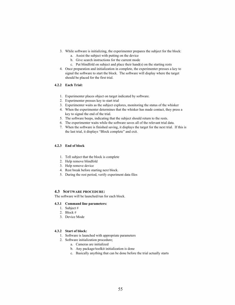
55
3. While software is initializing, the experimenter prepares the subject for the block: a. Assist the subject with putting on the device b. Give search instructions for the current mode c. Put blindfold on subject and place their hand(s) on the starting rests
4. Once preparation and initialization in complete, the experimenter presses a key to signal the software to start the block. The software will display where the target should be placed for the first trial.
4.2.2 Each Trial:
1. Experimenter places object on target indicated by software. 2. Experimenter presses key to start trial 3. Experimenter waits as the subject explores, monitoring the status of the whisker 4. When the experimenter determines that the whisker has made contact, they press a
key to signal the end of the trial. 5. The software beeps, indicating that the subject should return to the rests. 6. The experimenter waits while the software saves all of the relevant trial data. 7. When the software is finished saving, it displays the target for the next trial. If this is
the last trial, it displays “Block complete” and exit.
4.2.3 End of block
1. Tell subject that the block is complete 2. Help remove blindfold 3. Help remove device 4. Rest break before starting next block. 5. During the rest period, verify experiment data files
4.3 SOFTWARE PROCEDURE: The software will be launched/run for each block.
4.3.1 Command line parameters: 1. Subject # 2. Block # 3. Device Mode
4.3.2 Start of block: 1. Software is launched with appropriate parameters 2. Software initialization procedure;
a. Cameras are initialized b. Any package/toolkit initialization is done c. Basically anything that can be done before the trial actually starts
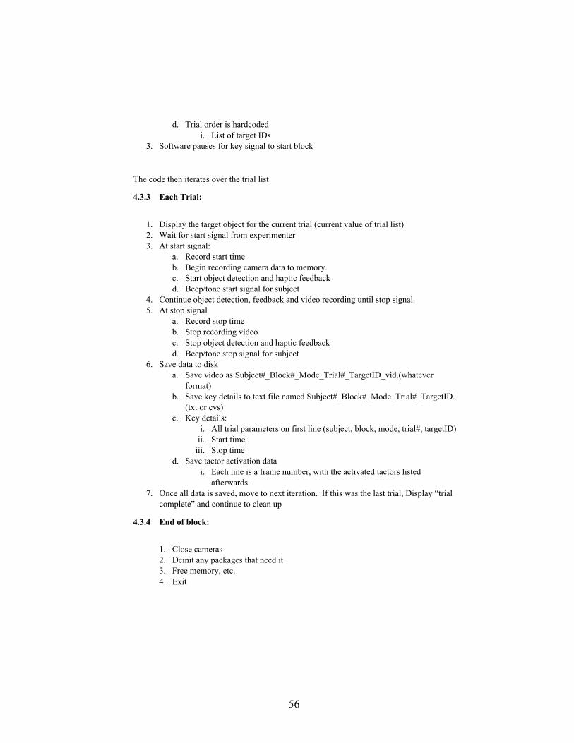
56
d. Trial order is hardcoded i. List of target IDs
3. Software pauses for key signal to start block
The code then iterates over the trial list
4.3.3 Each Trial:
1. Display the target object for the current trial (current value of trial list) 2. Wait for start signal from experimenter 3. At start signal:
a. Record start time b. Begin recording camera data to memory. c. Start object detection and haptic feedback d. Beep/tone start signal for subject
4. Continue object detection, feedback and video recording until stop signal. 5. At stop signal
a. Record stop time b. Stop recording video c. Stop object detection and haptic feedback d. Beep/tone stop signal for subject
6. Save data to disk a. Save video as Subject#_Block#_Mode_Trial#_TargetID_vid.(whatever
format) b. Save key details to text file named Subject#_Block#_Mode_Trial#_TargetID.
(txt or cvs) c. Key details:
i. All trial parameters on first line (subject, block, mode, trial#, targetID) ii. Start time
iii. Stop time d. Save tactor activation data
i. Each line is a frame number, with the activated tactors listed afterwards.
7. Once all data is saved, move to next iteration. If this was the last trial, Display “trial complete” and continue to clean up
4.3.4 End of block:
1. Close cameras 2. Deinit any packages that need it 3. Free memory, etc. 4. Exit

57
6.4.2 PalmSight Subject Instructions
1.1 SUBJECT PROCEDURE:
1.1.1 Start of block:
1. Experimenter assists with putting on the device (mode specific configuration). 2. Experimenter gives search instructions for the mode (see below). 3. Experimenter assists with putting on blindfold and placing arm(s) on the starting rests. 4. Experimenter removes drape from target array.
1.1.2 Each trial:
1. Subject hears a tone/beep that signals start of the trial 2. At signal, subject lifts hand(s) off of rests and begins to search for the object 3. The subject should search for the object until they feel/hear the whisker make contact.
or hear a beep signaling experimenter-observed contact 4. Once they make contact, they should stop moving, until they hear another beep/tone 5. At this beep/tone, they should return their hand(s) to the starting rests (guided by
experimenter if necessary) 6. After a short wait, the experiment continues on to the next trial at step 1.
1.1.3 End of block:
1. The experimenter drapes the targets and informs the subject when the block is over 2. Blindfold and device are removed 3. Rest break before starting next block
The experimenter will assist you with putting a device. It consists of a camera and some vibration dots. There is also a strap with a whisker. The camera and dots will sometimes be placed on your dominant hand, the one you use for eating and writing, and sometimes on the non-dominant hand. The device will stay on the same hand for a series of trials. The whisker is always on your dominant hand, which you will use to approach a target object that will be placed in different locations from trial to trial.
You will try to reach the target object with your hand held upright, palm facing forward. The camera tracks where your hand is relative to the target object. The vibration dots tell you how to move your hand to approach the object. You should follow the signals of the dots until you hit the target with the whisker.
Now let me tell you how to interpret the vibration dots. There are four dots arranged around the back of your hand at top, bottom, left and right. They tell you what direction to shift your hand in, to stay on track toward the target. So, for example, if the right dot buzzes, you should move slightly to the right until it stops, then move forward. Similarly, a buzz on the top means move your hand upward slightly before moving forward, and so on. If two vibrator buzz at the same time, like top and right, it means move on an angle in between the two.

58
When you first start a trial, you may have to move your hand around to put the object into the camera view. A vibration will tell you it’s been picked up, and how to move.
Some trials will provide you with one extra vibration point at the center of your hand. It tells you how far you are from the object. A stronger buzz means you are farther away; as you approach the object the buzz will get weaker, and you will be very close to hitting the target with the whisker.