palstar products are designed by palstar tradition for
TRANSCRIPT

Palstar products are designed by Hams for Hams carrying on the Palstar tradition for high-quality products designed and manufactured in Ohio, USA.
HF-AUTO AutomaticAntenna Tuner
l 2 watts to 1800 watts PEP
l 160 m to 6m
l Tuning time 10 secs or less
l Large 4 line display
l 12.5” x 6.5” x 16.5”
9676 N. Looney Rd,Piqua, OH 45356 USA
(937) 773-6255
(800) 773-7931(937) 773-8003 (Fax)www.palstar.com
HF-AUTO RF NETWORK Technical Manual
Designed and Manufactured in the USACopyright 2014 Palstar, Inc.
PALSTAR
PALSTAR
l N E T W O R K C O N F I G U R AT I O N : H i g h - P a s s n e t w o r k , s h u n t v a r i a b l e
1 6 μ H i n d u c t o r , s e r i e s � x e d 1 0 μ H i n d u c t o r
l D I F F E R E N T I A L C A PA C I T O R : 4 7 0 p F - 1 0 p F - 4 7 0 p F ;
V o l t a g e r a t i n g 5 . 5 k V
l L AND C: S t e p p e r m o t o r - c o n t r o l l e d
l F R E Q U E N C Y R A N G E : 1 . 8 M H Z t o 5 4 M H Z
l M AT C H I N G R A N G E : 8 : 1
l P O W E R R A N G E : 1 8 0 0 w a t t s P E P / C W 1 . 8 - 2 9 . 9 M H Z ;
8 0 0 w a t t s P E P 5 0 - 5 4 M H Z
l T U N I N G L E V E L : M i n i m u m l e v e l 2 w a t t s ,
s i n g l e t o n e c a r r i e r u p t o 2 0 0 w a t t s
l T U N I N G A C E S S T I M E : T y p i c a l l y < 1 0 s e c s 8 0 m t o 6 m ;
3 - 5 s e c s 8 0 m t o 1 6 0 m
l D U T Y C Y C L E : 1 0 0 % S S B A N D C W
l D I G I TA L D I S P L AY: R F P o w e r, S W R , F r e q u e n c y , A n t e n n a
s e l e c t i o n , P o s i t i o n o f L a n d C ;
M o d e s : A u t o , M a n u a l , B y p a s s , S e t u p
l O U T P U T : 3 O u t p u t c o n n e c t o r s S 0 - 2 3 9
l C H A S S I S & C O V E R : 1 1 g a . . 0 9 0 g o l d I r i d i t e Tr e a t e d A l u m i n i u m ,
P o w d e r - c o a t e d t o p c o v e r a n d f r o n t p a n e l
l D C P O W E R : 1 2 - 1 3 . 8 V D C a t 4 A m p s P e a k , 3 P i n
A m p h e n o l T y p e c o n n e c t o r c o r d s u p p l i e d
l D I M I N S I O N S : 1 2 . 5 ” W x 6 . 7 5 “ H x 1 4 ” D
l W E I G H T : 2 0 L B S , 9 K g
HF-AUTO SPECIFICATIONS
Page 14Page 1
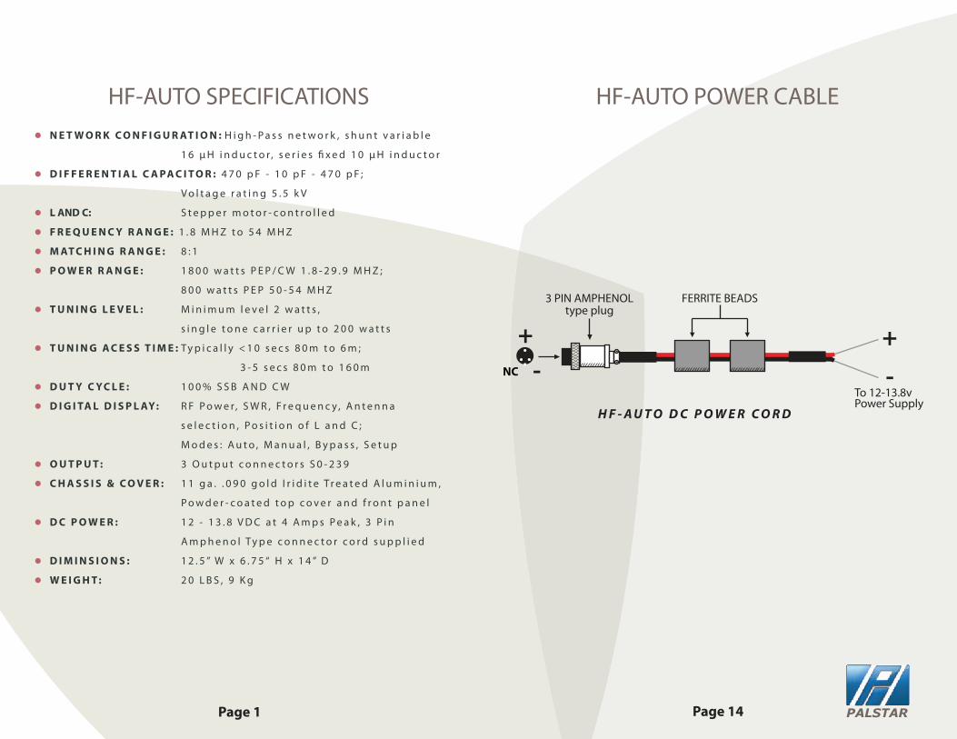
HF-AUTO POWER CABLE
PALSTAR
+-
To 12-13.8vPower Supply
3 PIN AMPHENOLtype plug
FERRITE BEADS
H F - A U T O D C P O W E R C O R D
+-NC

I F T H E R E I S M A I N T E N A N C E R E Q U I R E D I T W I L L M O S T L I K E LY B E R E L AT E D T O M E C H A N I C A L I S S U E S :
l R O L L E R S H A F T : t h e w h e e l r i d e s s h o u l d b e l u b r i c a t e d w i t h o u r f a c t o r y - m a d e c o n d u c t i v e g r e a s e . This grease is available from Palstar at NO CHARGE.l D I O X I T- D 5 s p r a y i s a l w a y s v e r y u s e f u l f o r c l e a n i n g t h e w i r e o n t h e r o l l e r c o i l . D o n o t u s e t h e s p r a y d i r e c t l y . P u t a s m a l l a m o u n t o n a c o t t o n c l o t h a n d h a n d w i p e t h e r o l l e r o n c e a y e a r w h i l e t u r n i n g t h e r o l l e r c r a n k .l A l l s e t s c r e w s a r e t h e C A P P O I N T t y p e a n d t a k e c a r e t o c a r e f u l l y t i g h t e n t h e s e s c r e w s w i t h a 5 / 1 6 ” a l l e n k e y w r e n c h , w h i c h i s a v a i l a b l e f r o m a n y h a r d w a r e o u t l e t .
R E PA I R O R R E P L A C E M E N T M O D U L E S l A l l P C B o a r d s a r e r e m o v e a b l e w i t h s t a n d a r d A m e r i c a n t o o l s i n c a s e o f f a i l u r e .l T h e r e a r p a n e l ( r e l a y P C B ) h a s c u s t o m S 0 - 2 3 9 c o n n e c t o r s t h a t c a n b e l o o s e n e d w i t h a 3 / 4 “ s o c k e t a n d 4 x 6 - 3 2 k e p s n u t s . R e m o v e t h e s e n u t s a n d t w o c o n n e c t i o n s f r o m t h e v a r i a b l e a n d t h e e n t i r e r e l a y P C B o a r d i s r e m o v a b l e w i t h o u t a s o l d e r i n g i r o n .l B o t h t h e f r o n t a n d r e a r p a n e l s c a n b e l o w e r e d b y r e m o v i n g t h e 3 c o u n t e r s i n k s c r e w s f r o m t h e b o t t o m e d g e o f e a c h p a n e l .
MAINTENANCE REQUIREMENTS
The HF-AUTO is a matching system that is a complete stand-alone RF Tuneable Auto T Network tuner. It is completely independent of data from an external source to determine frequency of tracking from Band to Band. As a result of this feature, the HF-AUTO will function with any transmitting device without interconnecting data cable attachments.
The HF-AUTO uses an RF Coupler that provides voltage and current information from 1.8 MHZ to 54 MHZ.
This informtion is then processed by a pair of processing devices that provide accurate phase oriented forward and re�ected values that are used in two TI processors to calculate SWR.
This allows for detection of frequency and SWR at very low levels, typically 2 watts, and is scaled to read these levels up to 1800 watts.
The processors establish the threshold for tuning and uses this information to see if a tuning sequence is required.
A preset voltage for all the frequencies are used to determine the positions of the variable di�erential capacitor and the roller inductor by a precise mechanical sprocket and kevlar belt system.
This determines with great accuracy and repeatability the exact location of L&C needed to execute a tune sequence. This system samples DC voltage and compares this to the intended frequency band and sees that if the SWR is more than the preset tuning set by the user then the steppers for L & C will adjust to that voltage which will represent the mimimum SWR.
This will be better than 1.2:1, typically 1.05.
Page 2Page 13
THEORY OF OPERATION
PALSTAR
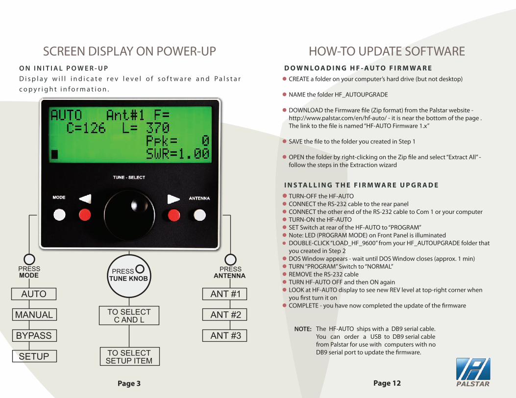
O N I N I T I A L P O W E R - U PD i s p l a y w i l l i n d i c a t e r e v l e v e l o f s o f t w a r e a n d P a l s t a r c o p y r i g h t i n f o r m a t i o n .
SCREEN DISPLAY ON POWER-UP
Page 12Page 3
HOW-TO UPDATE SOFTWARE
PRESS
TO SELECTC AND L
TO SELECTSETUP ITEM
D O W N L O A D I N G H F - A U T O F I R M WA R El CREATE a folder on your computer’s hard drive (but not desktop) l NAME the folder HF_AUTOUPGRADE
l DOWNLOAD the Firmware �le (Zip format) from the Palstar website - http://www.palstar.com/en/hf-auto/ - it is near the bottom of the page .
The link to the �le is named “HF-AUTO Firmware 1.x”
l SAVE the �le to the folder you created in Step 1
l OPEN the folder by right-clicking on the Zip �le and select “Extract All” - follow the steps in the Extraction wizard
l TURN-OFF the HF-AUTOl CONNECT the RS-232 cable to the rear panell CONNECT the other end of the RS-232 cable to Com 1 or your computerl TURN-ON the HF-AUTOl SET Switch at rear of the HF-AUTO to “PROGRAM”l Note: LED (PROGRAM MODE) on Front Panel is illuminatedl DOUBLE-CLICK “LOAD_HF_9600” from your HF_AUTOUPGRADE folder that
you created in Step 2l DOS Window appears - wait until DOS Window closes (approx. 1 min)l TURN “PROGRAM” Switch to “NORMAL” l REMOVE the RS-232 cablel TURN HF-AUTO OFF and then ON againl LOOK at HF-AUTO display to see new REV level at top-right corner when
you �rst turn it onl COMPLETE - you have now completed the update of the �rmware
NOTE:
I N S TA L L I N G T H E F I R M WA R E U P G R A D E
ANT #1
ANT #2
ANT #3
AUTO
MANUAL
BYPASS
SETUP
The HF-AUTO ships with a DB9 serial cable. You can order a USB to DB9 serial cable from Palstar for use with computers with no DB9 serial port to update the �rmware.
MODE TUNE KNOBPRESS PRESS
ANTENNA
PALSTAR

Page 4Page 11
SETUP MODEHF-AUTO Firmware Summary
v1.18: - new default position settings made for the positioning of the C and L with a given frequency range; - added menu option to clear out the memory o�set positions for the C and L with a given frequency range; - removed limits on the C and L o�set position values; - added menu selection of the Amp-Key relay state when no RF power is detected; - added ability in manual mode to store a memory position using the Right Arrow button;v1.19: - changes regarding operation with the MARS frequencies.v1.20: - allowed for the use of the new relay board with the proper jumper selection; - added additional memory presets between 7.0 MHz and 14.0 MHz; - manual mode now allowed the Left Arrow Button to return to Auto mode.v1.21: - corrected problem where the display was not being updated after pressing left arrow button and would make the unit go from Manual Mode to Auto Mode.v1.22: - minor display corrections: UNABLE TO TUNE message remained on display in error after a new tune operation started.v1.23: - added Setup Menu item to select AUTO STORE to be ON or OFF; - added Setup Menu item to select DELAY TUNE SWR to be ON or OFF; - provided for using Ant 3 selection with dummy load by changing to AUTO ANT SWITCH MODE state by pressing and holding of the ANTENNA button; - added memory locations to have memory settings every 50 kHz from 28 MHz to 29.7 MHz.v1.24: - removed Amp Key Relay Menu items; - corrected problem where the display could be blanked out after the unit remained in the Setup Menu for an extended time.v1.25: - corrected an occassional problem in Auto Tune Mode if the unit has AUTO ANT SWITCH set to ON; - made improvements in the Auto Tune operation to reduce the time needed to �nd the C and L tune - positions when a given frequency is �rst applied.v1.26: - corrected a problem where some units were incorrectly reading EEPROM calibration and setting values.v1.27: - removed restrictions in manual mode that prevent storing of new C and L positions when those changes are only of a minimal number of steps. The restriction is there to prevent the auto tune mode causing excessive writes to the EEPROM; - corrected occassional problems in �nding the absolute best match when v1.25 changes were made; - added to the operation when holding the ANTENNA button to select BYPASS MODE when AUTO ANT SWITCH is turned OFF and select AUTO MODE when AUTO ANT SWITCH is turned ON.v1.28 not released.v1.29 - The selection of the antenna port in an auto frequency selection mode now is programmable for each of the ten di�erent HF bands; - The INITIALIZE PRESETS menu option has been removed; - The QUICK TUNE menu option has been removed; - The last frequency of transmission is saved on power down and the inductor and antenna relay settings are restored for that same frequency at power up in auto antenna mode; - The power reading no longer has an option to be average power. Only peak power is displayed; - The accuracy of the peak power has been improved; - Added menu option to have last SWR reading remain on the display after power is removed; - Added menu option to have last Power reading remain on the display after power is removed.
RANGE (WATTS):
TUNE LEVEL:
BACKLIGHT:
POWER UP MODE:
STEP SPEED:
AUTO ANT SW:
RETUNE DELAY:
POWER UP ANT:
AUTO STORE:
DELAY TUNE SWR:
LAST SWR DISP:
LAST POWER DISP:
100 | 250 | 1000 | 2500
1 – DIM | 2 - BRIGHT
AUTO | MANUAL | BYPASS
HIGH | MED | LOW
ON | OFF
ADJ 1-3 SECS
ANT 1 | 2 | 3
ON | OFF
ON | OFF
ON | OFF
ON | OFF
1.05 TO 1.64
FOR LICENSED USERS ONLYMARS MIN-MAXMARS FREQ ADJ
to SELECT MENU
PRESSTUNE KNOB
PRESS & ADJUST
with TUNE KNOBto ADJUST VALUES
PRESSRED BUTTONS
PALSTAR

Page 10Page 5
TUNER OPERATION
1. CONNECT the transceiver to the RF INPUT chassis connector at the rear of the back panel 2. CONNECT a dummy load to one of the coax outputs or your desired antenna3. APPLY a single tone level greater than 5 watts (use FM MODE) typically 5 to 50 watts4. DISPLAY will indicate Frequency, Power Level, SWR, and Numerical value for C and L
NOTE: To execute a tune sequence at another band or frequency lower thepower of the transceiver or any other transmitting device to low power and change frequency and the tuner will immediately follow to the new location. You can also click the PTT button on your microphone in FM MODE and accomplish the same at the lowest power level
TUNING THE HF-AUTO
Applying only a short burst of single tone power to the HF-AUTO will allow the tuner to pretune to a memory segment containing the desired frequency. ANOTHER application of RF Power must be applied to completethe �nal tune condition where high power may be applied. You can alsoapply single tone power continuously until the �nal tune cycle has compledand get the same result. Trying to tune at high power without executing the�nal tune condition could damage the tuner.
P L A C E T U N E R I N A U T O M O D E W I T H G R E Y M O D E B U T T O N
INSIDE VIEW
ROLLER INDUCTOR
VARIABLE CAPACITOR STEPPER MOTORSUPPORT SUB-PANEL
PALSTAR will o�er a fully remote version of the base version in the near future. However, in certain cases where there is DC power available at a reasonable distance you can operate this base version in the AUTO MODE. Other functions would of course not be available.
The base version is frequency sensing you need only to insert a metering device that could monitor re�ected power in the transmitting location.
REMOTE OPERATION
PULLEY/BELT SYSTEM
PALSTAR

Page 6Page 7
SAVING MEMORY LOCATIONS
l TUNE the HF-AUTO using a low power FM or CW signall MANUALLY tune L&C for best SWR while power appliedl While power is still applied push red button to the right of the tuning knob and hold for 2 seconds or more until the display says “SETTINGS CHANGED”l Remove power and release the red buttonl The frequency is now savedl To return to AUTO MODE push left red button
DIVISIONS IN THE FREQUENCY BANDS FOR SETTINGS
FREQUENCY IN MHZ # OF SETTINGS SPACED
1.8 MHZ to 20 MHZ 51 4 Khz3.5 MHZ to 4.0 MHZ 51 10 Khz7.0 MHZ to 7.3 MHZ 36 50 Khz10.1 MHZ to 10.150 MHZ 2 50 Khz14.0 MHZ to 14.350 MHZ 18 40 Khz18.068 MHZ to 18.168 MHZ 3 50 Khz21.0 MHZ to 21.450 MHZ 5 100 Khz24.890 MHZ to 24.990 MHZ 1 500 Khz28.0 MHZ to 29.70 MHZ 51 500 Khz50.0 MHZ to 54.0 MHZ 101 40 Khz
MARS FREQUENCY 707 4 Khz to 500 Khz
FOR ALL TUNABLE FREQUENCIES FROM 1.8 - 30 MHZ, 40 MHZ THROUGH 41 MHZ AND 50 MHZ TO 54 MHZ THERE ARE 1193 SUBDIVISIONS OR MEMORY POSITIONS.
REAR PANEL OF HF-AUTO
ANTENNA OUTPUTS
OUTPUT
14.200
TRANSCEIVER
FIRMWARE UPDATE/PROGRAM SWITCH
RS-232
DC INPUT12 - 13.8 VDC
CHASSIS GROUNDWING-NUT
@ 4 AMPS
PALSTAR

INSIDE VIEW OF HF-AUTO
COPYRIGHT PALSTAR 2011-2014©
limit
limit
limit
step
per
Ant
.#3
RF
Path
PCB
J1 J2 J3
Ant
.#1
J4Pf
wd/
Prev
Freq
.PC
B
Ant
.#2
Xmtr.
SC
1
SC
1
Diff
eren
tial
Tee
Net
wor
k
SC
2
SC
3
SC
2
SC
3
Logi
c / D
ispl
ay/B
utto
nsPC
B
Inte
rface
PCB
8pin 6pin 2DC10pin
4pin
step
per
8pin 8pin
Step
per
Mot
ors
4pin 4pin
P1
DC
J7J6J5R
S-2
32
On/
Off
Switc
h
2D
C2
DC
10pi
n
8pin
6pi
n
P2
P2
P3
P3
P4
P4
P5
P5
P6
P7
P8
P9
P10
P11
SW
1P
rogr
am/
Run
J1-J
4=
SO
-239
J5=
DE
-9 F
emal
eS
W1
=S
PS
Tre
cess
edsw
itch
(ope
n=
RU
N)
J6-J
7=
RC
AP
hono
Fem
ale
P1
=D
Cm
ale
conn
ecto
r(>5
A)
PC
Bco
nnec
tors
are
.1"m
ale
4-10
pins
All
mat
ing
cabl
eco
nnec
tors
are
fem
ale
P5-
P6
=A
MP
mat
e-N
-lok
P9-
P11
=4
pin
0.1"
spac
ing
P3
=6
pin
0.1"
spac
ing
P2,
P7-
P8
=8
pin
0.1"
spac
ing
P4
=10
pin
0.1"
spac
ing
Ste
pper
mot
ors
now
have
diffe
rent
wiri
ngw
ithno
pins
havi
ng2
wire
s.8
pin
conn
ecto
ris
com
patib
lew
ithol
d6
pin
cabl
esif
conn
ect
topi
ns2-
7.
HF-AUTO SCHEMATICPALSTAR