panasonic ilmalämpöpumput korjaa ja huoltaa ... · 1 functions remote control off/on operation...
TRANSCRIPT

1 Functions 2
2 Product Specifications 5
3 Dimensions 9
4 Refrigeration Cycle Diagram 11
5 Block Diagram 12
6 Wiring Diagram 13
7 Operation Details 14
8 Installation Instructions 27
9 Installation and Servicing Air Conditioner Using R410A 37
© 2003 Matsushita Electric Industrial Co., Ltd. Allrights reserved. Unauthorized copying anddistribution is a violation of law.
CS-PW9CKECU-PW9CKECS-PW12CKECU-PW12CKE
10 Servicing Information 48
11 Troubleshooting Guide 52
12 Technical Data 54
13 Exploded View 58
14 Replacement Parts List 59
15 Exploded View 60
16 Replacement Parts List 61
17 Electronic Circuit Diagram 62
18 Electronic Circuit Diagram(Remote Control) 65
Room Air Conditioner
CONTENTS Page Page
Order No. GMAC0311009C2
Panasonic ilmalämpöpumput korjaa ja huoltaa pääkaupunkiseudulla: Jäähdytinpalvelu RefGroup Oy
www.ilmalämpöpumput.com
1 Functions
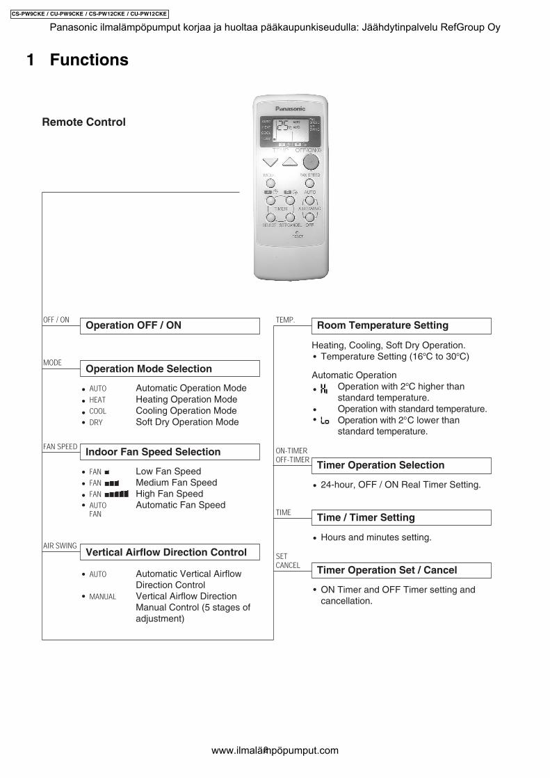
Remote Control
Operation OFF / ONOFF / ON
Room Temperature SettingTEMP.
Operation Mode Selection
AUTO Automatic Operation ModeHEAT Heating Operation ModeCOOL Cooling Operation ModeDRY Soft Dry Operation Mode
MODE
TIME Time / Timer Setting
Hours and minutes setting.
Indoor Fan Speed SelectionFAN SPEED
FAN Low Fan SpeedFAN Medium Fan SpeedFAN High Fan SpeedAUTO Automatic Fan SpeedFAN
Vertical Airflow Direction Control
24-hour, OFF / ON Real Timer Setting.
ON-TIMER
OFF-TIMERTimer Operation Selection
SET
CANCEL Timer Operation Set / Cancel
ON Timer and OFF Timer setting andcancellation.
AIR SWING
AUTO Automatic Vertical AirflowDirection Control
MANUAL Vertical Airflow DirectionManual Control (5 stages ofadjustment)
Heating, Cooling, Soft Dry Operation.Temperature Setting (16oC to 30oC)
Automatic OperationOperation with 2oC higher thanstandard temperature.Operation with standard temperature.Operation with 2oC lower thanstandard temperature.
•••
•
•••
•
•
•
•
••
•
•
•
•
2
CS-PW9CKE / CU-PW9CKE / CS-PW12CKE / CU-PW12CKE
Panasonic ilmalämpöpumput korjaa ja huoltaa pääkaupunkiseudulla: Jäähdytinpalvelu RefGroup Oy
www.ilmalämpöpumput.com
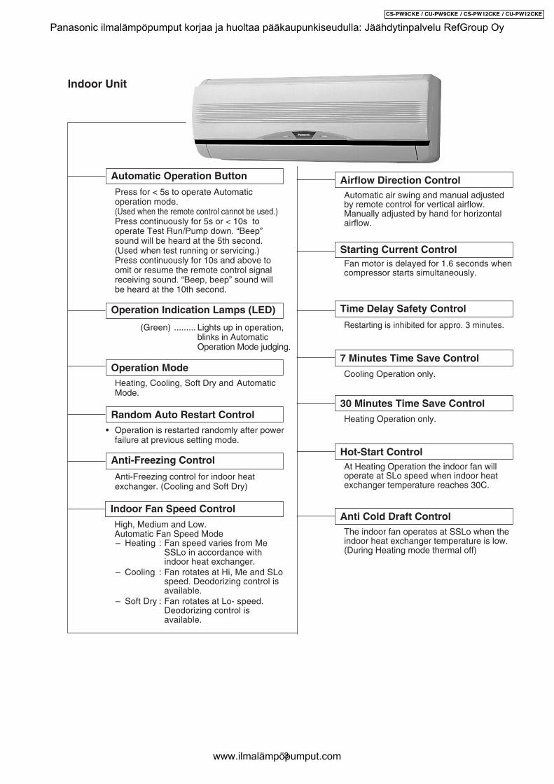
Indoor Unit
Random Auto Restart Control• Operation is restarted randomly after power
failure at previous setting mode.
Anti-Freezing Control
Anti-Freezing control for indoor heatexchanger. (Cooling and Soft Dry)
Indoor Fan Speed Control High, Medium and Low. Automatic Fan Speed Mode
– Heating : Fan speed varies from Me SSLo in accordance withindoor heat exchanger.
– Cooling : Fan rotates at Hi, Me and SLospeed. Deodorizing control isavailable.
– Soft Dry : Fan rotates at Lo- speed.Deodorizing control isavailable.
Automatic air swing and manual adjustedby remote control for vertical airflow.
Manually adjusted by hand for horizontalairflow.
Airflow Direction ControlAutomatic Operation Button
Press for < 5s to operate Automaticoperation mode.(Used when the remote control cannot be used.)
Press continuously for 5s or < 10s tooperate Test Run/Pump down. “Beep”sound will be heard at the 5th second.(Used when test running or servicing.)
Press continuously for 10s and above toomit or resume the remote control signalreceiving sound. “Beep, beep” sound willbe heard at the 10th second.
Operation Indication Lamps (LED)
(Green) ......... Lights up in operation,blinks in AutomaticOperation Mode judging.
Operation Mode Heating, Cooling, Soft Dry and Automatic
Mode.
Time Delay Safety Control
Restarting is inhibited for appro. 3 minutes.
Starting Current Control
7 Minutes Time Save Control
Cooling Operation only.
Fan motor is delayed for 1.6 seconds whencompressor starts simultaneously.
30 Minutes Time Save Control Heating Operation only.
Hot-Start Control At Heating Operation the indoor fan will
operate at SLo speed when indoor heatexchanger temperature reaches 30C.
Anti Cold Draft Control The indoor fan operates at SSLo when the
indoor heat exchanger temperature is low.(During Heating mode thermal off)
3
CS-PW9CKE / CU-PW9CKE / CS-PW12CKE / CU-PW12CKE
Panasonic ilmalämpöpumput korjaa ja huoltaa pääkaupunkiseudulla: Jäähdytinpalvelu RefGroup Oy
www.ilmalämpöpumput.com
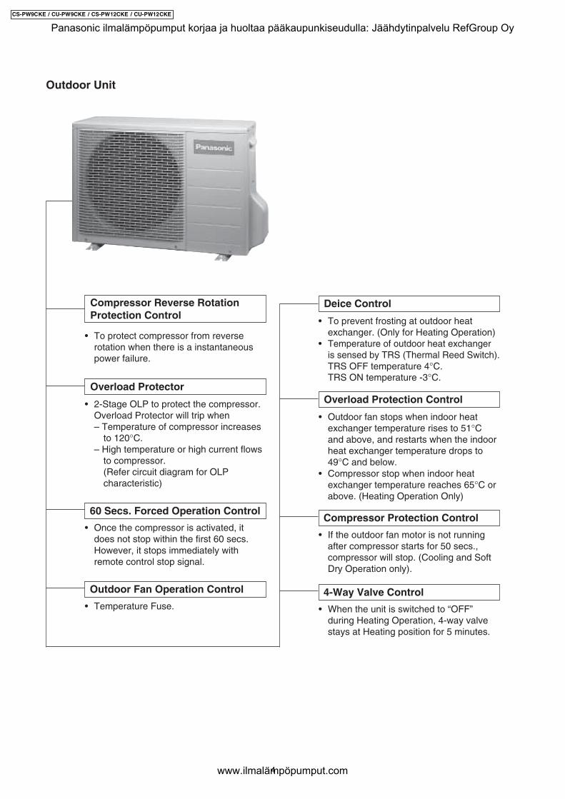
Outdoor Unit
• To protect compressor from reverserotation when there is a instantaneouspower failure.
60 Secs. Forced Operation Control
• Once the compressor is activated, itdoes not stop within the first 60 secs.However, it stops immediately withremote control stop signal.
Overload Protector
• 2-Stage OLP to protect the compressor.Overload Protector will trip when– Temperature of compressor increases
to 120°C.– High temperature or high current flows
to compressor.(Refer circuit diagram for OLPcharacteristic)
Compressor Reverse RotationProtection Control
Outdoor Fan Operation Control
• Temperature Fuse.4-Way Valve Control
• When the unit is switched to “OFF”during Heating Operation, 4-way valvestays at Heating position for 5 minutes.
Overload Protection Control
• Outdoor fan stops when indoor heatexchanger temperature rises to 51°Cand above, and restarts when the indoorheat exchanger temperature drops to49°C and below.
• Compressor stop when indoor heatexchanger temperature reaches 65°C orabove. (Heating Operation Only)
Deice Control
• To prevent frosting at outdoor heatexchanger. (Only for Heating Operation)
• Temperature of outdoor heat exchangeris sensed by TRS (Thermal Reed Switch).TRS OFF temperature 4°C.TRS ON temperature -3°C.
Compressor Protection Control
• If the outdoor fan motor is not runningafter compressor starts for 50 secs.,compressor will stop. (Cooling and SoftDry Operation only).
4
CS-PW9CKE / CU-PW9CKE / CS-PW12CKE / CU-PW12CKE
Panasonic ilmalämpöpumput korjaa ja huoltaa pääkaupunkiseudulla: Jäähdytinpalvelu RefGroup Oy
www.ilmalämpöpumput.com
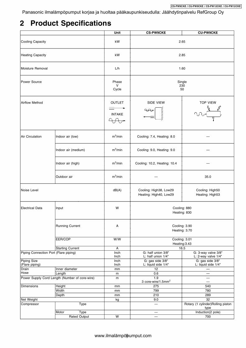
2 Product SpecificationsUnit CS-PW9CKE CU-PW9CKE
Cooling Capacity kW 2.65
Heating Capacity kW 2.85
Moisture Removal L/h 1.60
Power Source PhaseV
Cycle
Single23050
Airflow Method OUTLET
INTAKE
SIDE VIEW TOP VIEW
Air Circulation Indoor air (low) m3/min Cooling: 7.4, Heating: 8.0 —
Indoor air (medium) m3/min Cooling: 9.0, Heating: 9.0 —
Indoor air (high) m3/min Cooling: 10.2, Heating: 10.4 —
Outdoor air m3/min — 35.0
Noise Level dB(A) Cooling: High38, Low29 Cooling: High50Heating: High40, Low29 Heating: High53
Electrical Data Input W Cooling: 880Heating: 830
Running Current A Cooling: 3.90Heating: 3.70
EER/COP W/W Cooling: 3.01Heating:3.43
Starting Current A 16.5Piping Connection Port (Flare piping) Inch
InchG: half union 3/8"L: half union 1/4"
G: 3-way valve 3/8"L: 2-way valve 1/4"
Piping Size(Flare piping)
InchInch
G: gas side 3/8"L: liquid side 1/4"
G: gas side 3/8"L: liquid side 1/4"
DrainHose
Inner diameter mm 12 —Length m 0.6 —
Power Supply Cord Length (Number of core-wire) m 1.93 core-wire/1.5mm2
——
Dimensions Height mm 275 540Width mm 799 780Depth mm 210 289
Net Weight kg 9.0 32Compressor Type — Rotary (1 cylinder)Rolling piston
typeMotor Type — Induction(2 pole)
Rated Output W — 700
5
CS-PW9CKE / CU-PW9CKE / CS-PW12CKE / CU-PW12CKE
Panasonic ilmalämpöpumput korjaa ja huoltaa pääkaupunkiseudulla: Jäähdytinpalvelu RefGroup Oy
www.ilmalämpöpumput.com
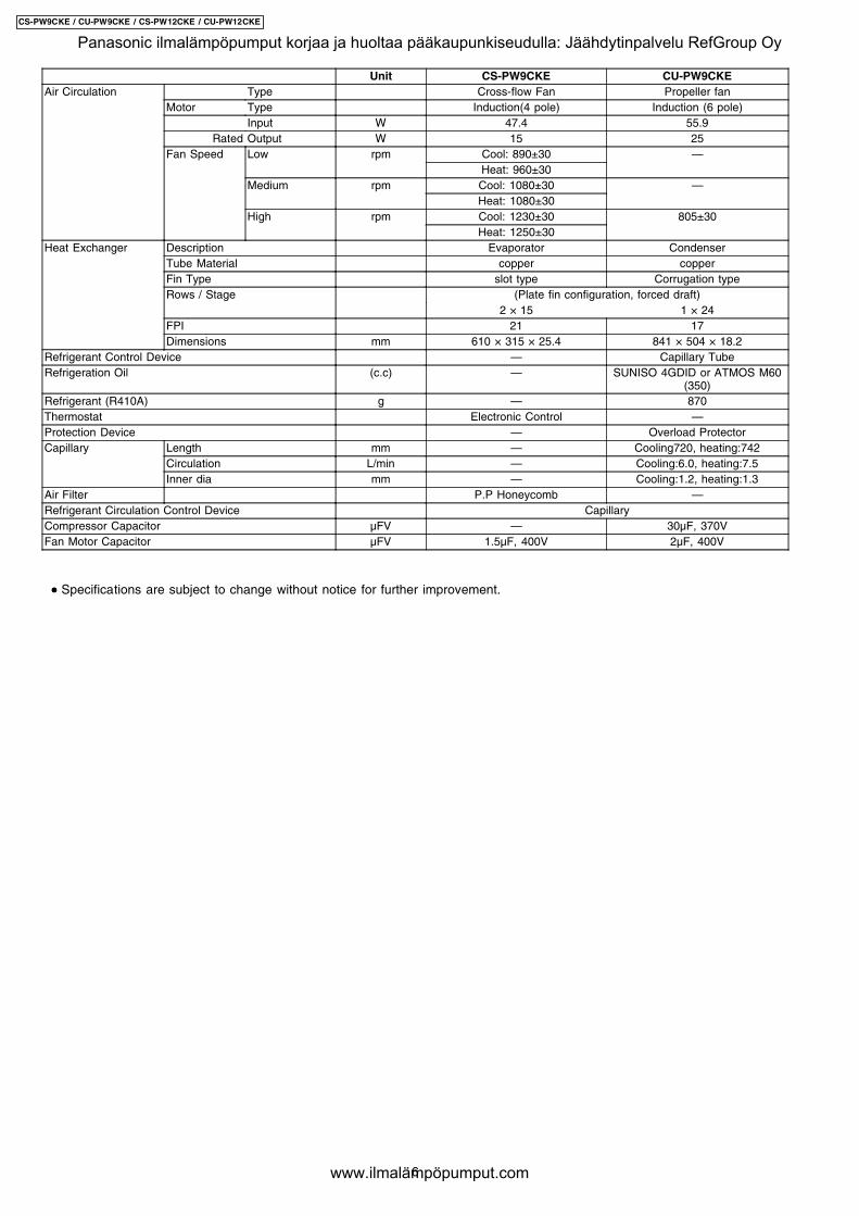
Unit CS-PW9CKE CU-PW9CKEAir Circulation Type Cross-flow Fan Propeller fan
Motor Type Induction(4 pole) Induction (6 pole)Input W 47.4 55.9
Rated Output W 15 25Fan Speed Low rpm Cool: 890±30 —
Heat: 960±30Medium rpm Cool: 1080±30 —
Heat: 1080±30High rpm Cool: 1230±30 805±30
Heat: 1250±30Heat Exchanger Description Evaporator Condenser
Tube Material copper copperFin Type slot type Corrugation typeRows / Stage (Plate fin configuration, forced draft)
2 × 15 1 × 24FPI 21 17Dimensions mm 610 × 315 × 25.4 841 × 504 × 18.2
Refrigerant Control Device — Capillary TubeRefrigeration Oil (c.c) — SUNISO 4GDID or ATMOS M60
(350)Refrigerant (R410A) g — 870Thermostat Electronic Control —Protection Device — Overload ProtectorCapillary Length mm — Cooling720, heating:742
Circulation L/min — Cooling:6.0, heating:7.5Inner dia mm — Cooling:1.2, heating:1.3
Air Filter P.P Honeycomb —Refrigerant Circulation Control Device CapillaryCompressor Capacitor µFV — 30µF, 370VFan Motor Capacitor µFV 1.5µF, 400V 2µF, 400V
• • • • Specifications are subject to change without notice for further improvement.
6
CS-PW9CKE / CU-PW9CKE / CS-PW12CKE / CU-PW12CKE
Panasonic ilmalämpöpumput korjaa ja huoltaa pääkaupunkiseudulla: Jäähdytinpalvelu RefGroup Oy
www.ilmalämpöpumput.com
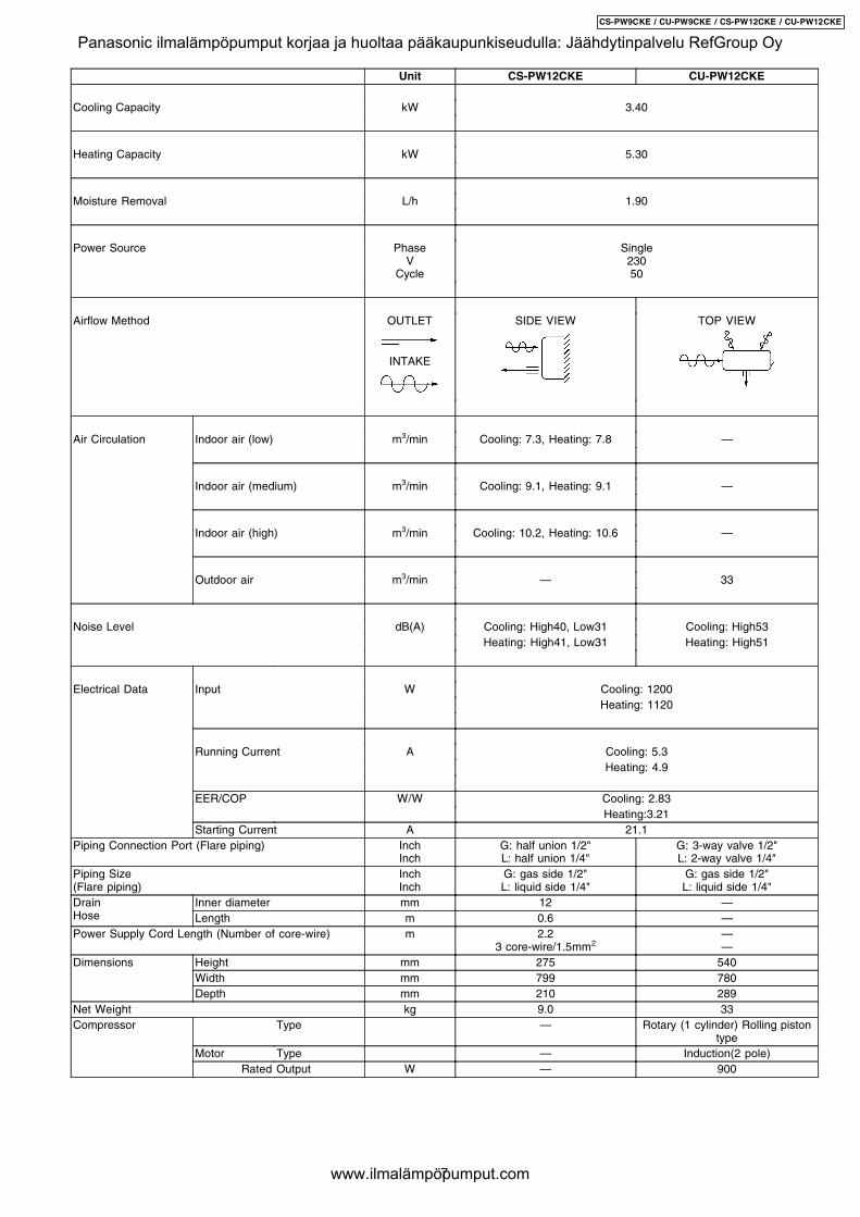
Unit CS-PW12CKE CU-PW12CKE
Cooling Capacity kW 3.40
Heating Capacity kW 5.30
Moisture Removal L/h 1.90
Power Source PhaseV
Cycle
Single23050
Airflow Method OUTLET
INTAKE
SIDE VIEW TOP VIEW
Air Circulation Indoor air (low) m3/min Cooling: 7.3, Heating: 7.8 —
Indoor air (medium) m3/min Cooling: 9.1, Heating: 9.1 —
Indoor air (high) m3/min Cooling: 10.2, Heating: 10.6 —
Outdoor air m3/min — 33
Noise Level dB(A) Cooling: High40, Low31 Cooling: High53Heating: High41, Low31 Heating: High51
Electrical Data Input W Cooling: 1200Heating: 1120
Running Current A Cooling: 5.3Heating: 4.9
EER/COP W/W Cooling: 2.83Heating:3.21
Starting Current A 21.1Piping Connection Port (Flare piping) Inch
InchG: half union 1/2"L: half union 1/4"
G: 3-way valve 1/2"L: 2-way valve 1/4"
Piping Size(Flare piping)
InchInch
G: gas side 1/2"L: liquid side 1/4"
G: gas side 1/2"L: liquid side 1/4"
DrainHose
Inner diameter mm 12 —Length m 0.6 —
Power Supply Cord Length (Number of core-wire) m 2.23 core-wire/1.5mm2
——
Dimensions Height mm 275 540Width mm 799 780Depth mm 210 289
Net Weight kg 9.0 33Compressor Type — Rotary (1 cylinder) Rolling piston
typeMotor Type — Induction(2 pole)
Rated Output W — 900
7
CS-PW9CKE / CU-PW9CKE / CS-PW12CKE / CU-PW12CKE
Panasonic ilmalämpöpumput korjaa ja huoltaa pääkaupunkiseudulla: Jäähdytinpalvelu RefGroup Oy
www.ilmalämpöpumput.com
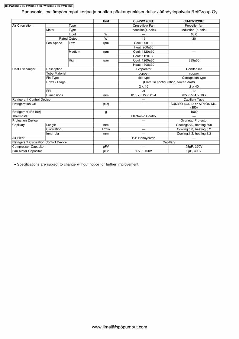
Unit CS-PW12CKE CU-PW12CKEAir Circulation Type Cross-flow Fan Propeller fan
Motor Type Induction(4 pole) Induction (6 pole)Input W — 63.6
Rated Output W 15 30Fan Speed Low rpm Cool: 900±30 —
Heat: 960±30Medium rpm Cool: 1120±30 —
Heat: 1120±30High rpm Cool: 1260±30 835±30
Heat: 1300±30Heat Exchanger Description Evaporator Condenser
Tube Material copper copperFin Type slot type Corrugation typeRows / Stage (Plate fin configuration, forced draft)
2 × 15 2 × 40FPI 21 17Dimensions mm 610 × 315 × 25.4 735 × 504 × 18.7
Refrigerant Control Device — Capillary TubeRefrigeration Oil (c.c) — SUNISO 4GDID or ATMOS M60
(350)Refrigerant (R410A) g — 1000Thermostat Electronic Control —Protection Device — Overload ProtectorCapillary Length mm — Cooling:270, heating:590
Circulation L/min — Cooling:5.0, heating:8.2Inner dia mm — Cooling:1.2, heating:1.3
Air Filter P.P Honeycomb —Refrigerant Circulation Control Device CapillaryCompressor Capacitor µFV — 25µF, 370VFan Motor Capacitor µFV 1.5µF 400V 2µF, 400V
• • • • Specifications are subject to change without notice for further improvement.
8
CS-PW9CKE / CU-PW9CKE / CS-PW12CKE / CU-PW12CKE
Panasonic ilmalämpöpumput korjaa ja huoltaa pääkaupunkiseudulla: Jäähdytinpalvelu RefGroup Oy
www.ilmalämpöpumput.com
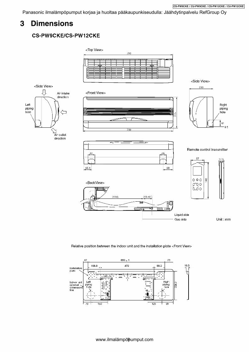
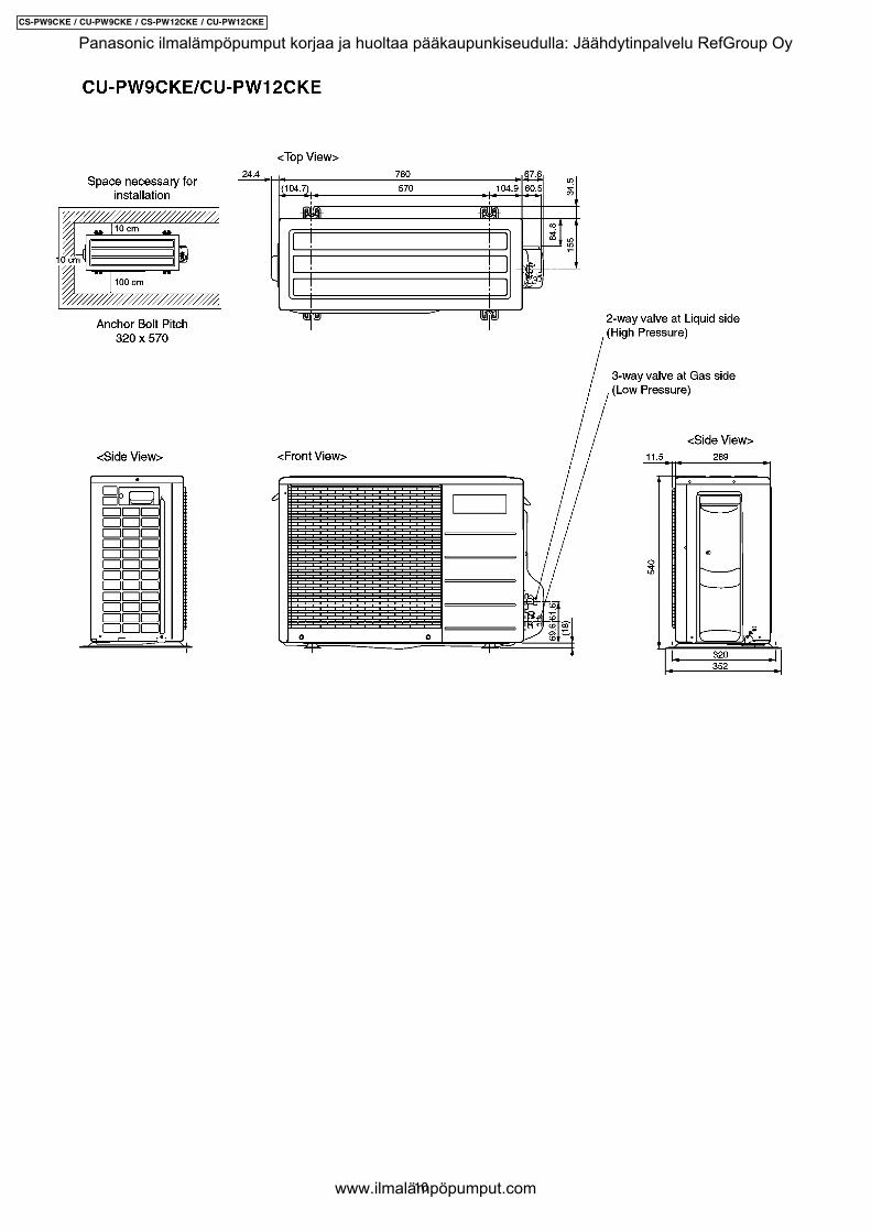
3 Dimensions
9
CS-PW9CKE / CU-PW9CKE / CS-PW12CKE / CU-PW12CKE
Panasonic ilmalämpöpumput korjaa ja huoltaa pääkaupunkiseudulla: Jäähdytinpalvelu RefGroup Oy
www.ilmalämpöpumput.com
10
CS-PW9CKE / CU-PW9CKE / CS-PW12CKE / CU-PW12CKE
Panasonic ilmalämpöpumput korjaa ja huoltaa pääkaupunkiseudulla: Jäähdytinpalvelu RefGroup Oy
www.ilmalämpöpumput.com
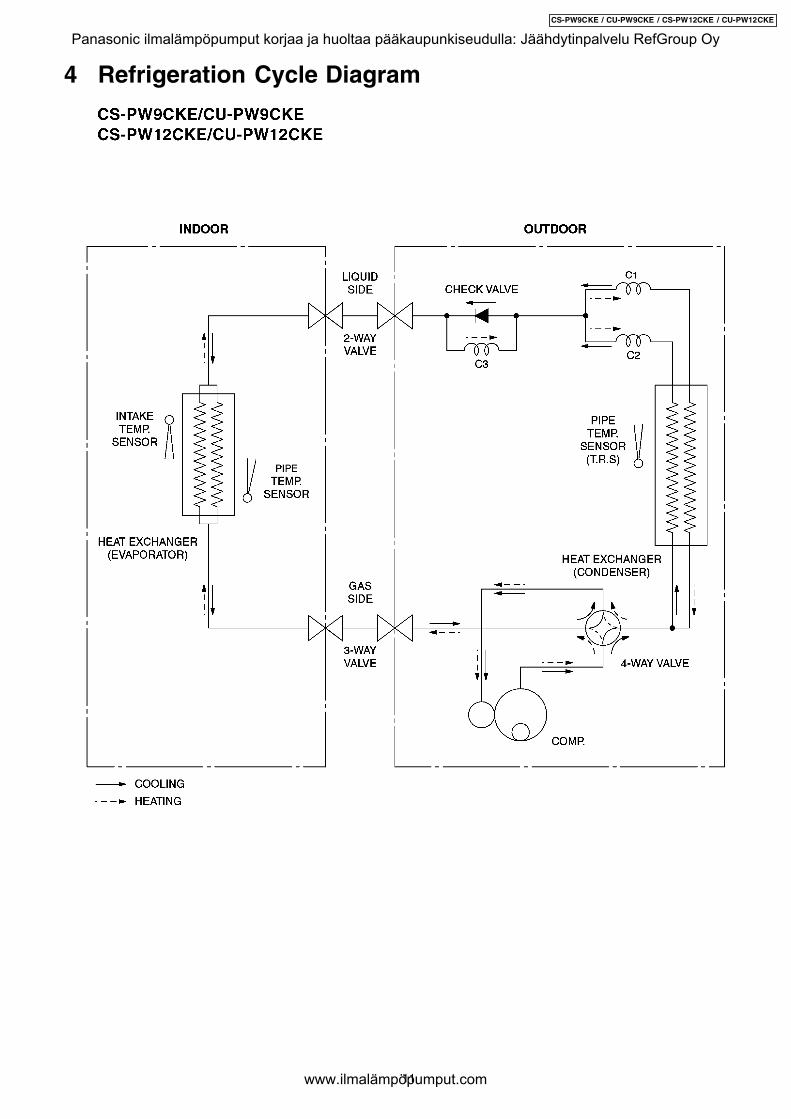
4 Refrigeration Cycle Diagram
11
CS-PW9CKE / CU-PW9CKE / CS-PW12CKE / CU-PW12CKE
Panasonic ilmalämpöpumput korjaa ja huoltaa pääkaupunkiseudulla: Jäähdytinpalvelu RefGroup Oy
www.ilmalämpöpumput.com
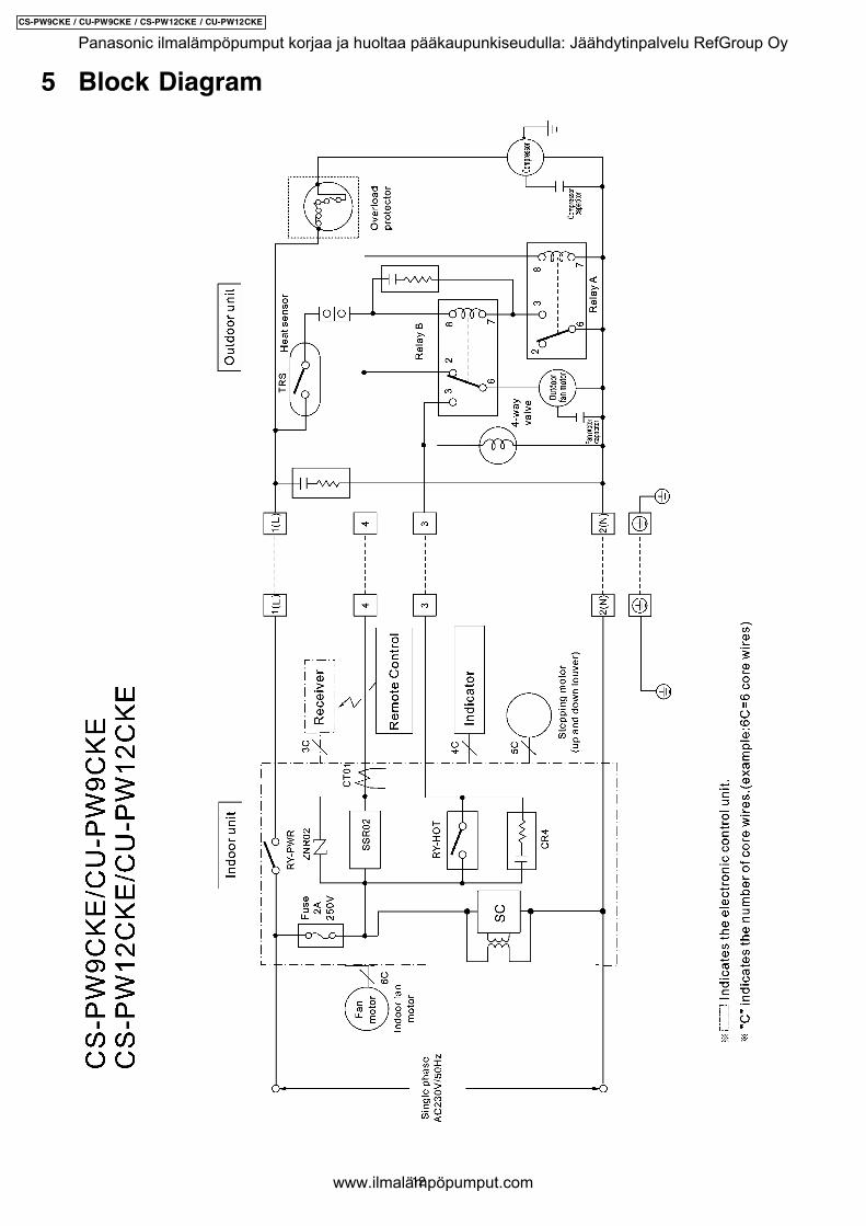
5 Block Diagram
12
CS-PW9CKE / CU-PW9CKE / CS-PW12CKE / CU-PW12CKE
Panasonic ilmalämpöpumput korjaa ja huoltaa pääkaupunkiseudulla: Jäähdytinpalvelu RefGroup Oy
www.ilmalämpöpumput.com

6 Wiring Diagram
13
CS-PW9CKE / CU-PW9CKE / CS-PW12CKE / CU-PW12CKE
Panasonic ilmalämpöpumput korjaa ja huoltaa pääkaupunkiseudulla: Jäähdytinpalvelu RefGroup Oy
www.ilmalämpöpumput.com
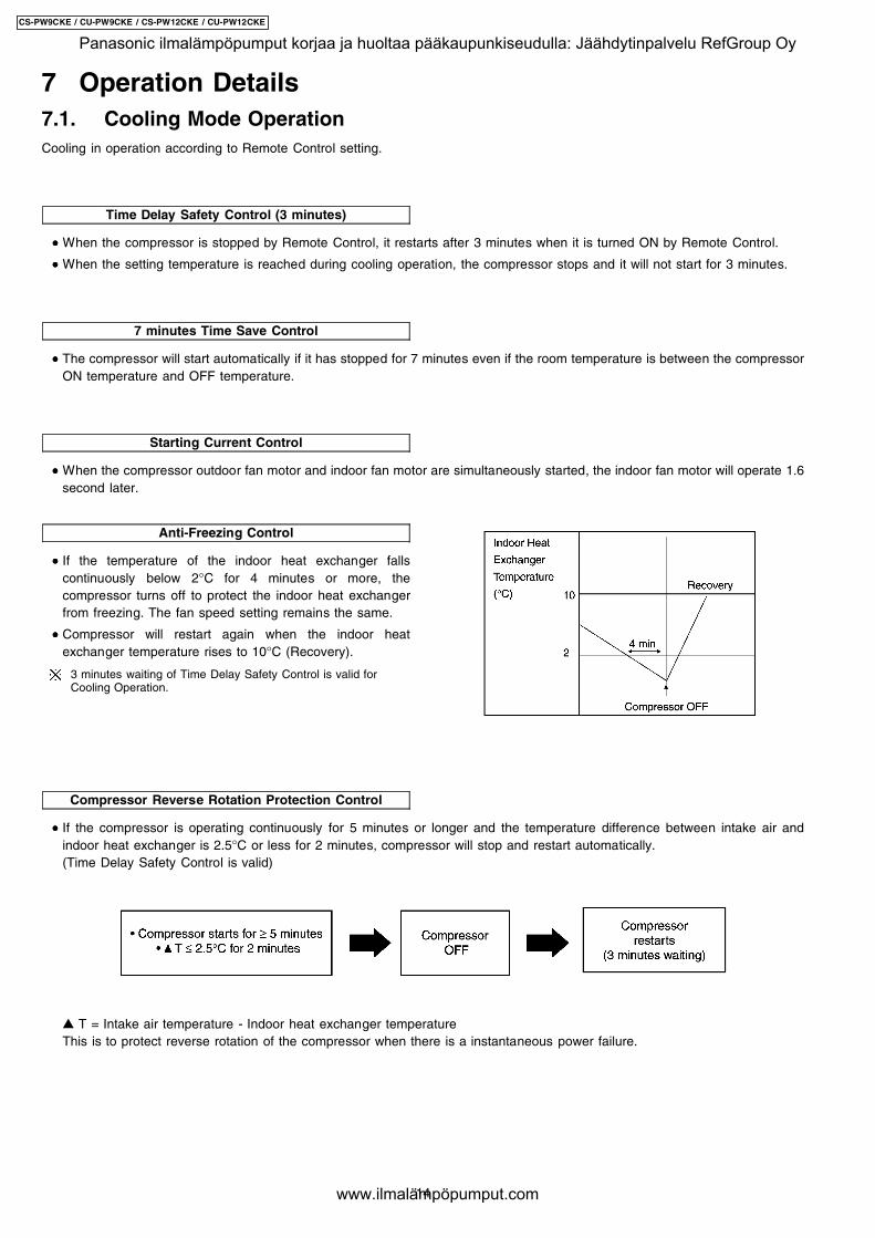
Cooling in operation according to Remote Control setting.
Time Delay Safety Control (3 minutes)
7 minutes Time Save Control
Starting Current Control
Anti-Freezing Control
• • • • If the temperature of the indoor heat exchanger fallscontinuously below 2°C for 4 minutes or more, thecompressor turns off to protect the indoor heat exchangerfrom freezing. The fan speed setting remains the same.
• • • • Compressor will restart again when the indoor heatexchanger temperature rises to 10°C (Recovery).
3 minutes waiting of Time Delay Safety Control is valid forCooling Operation.
Compressor Reverse Rotation Protection Control
7 Operation Details7.1. Cooling Mode Operation
• • • • When the compressor is stopped by Remote Control, it restarts after 3 minutes when it is turned ON by Remote Control.
• • • • When the setting temperature is reached during cooling operation, the compressor stops and it will not start for 3 minutes.
• • • • The compressor will start automatically if it has stopped for 7 minutes even if the room temperature is between the compressorON temperature and OFF temperature.
• • • • When the compressor outdoor fan motor and indoor fan motor are simultaneously started, the indoor fan motor will operate 1.6second later.
• • • • If the compressor is operating continuously for 5 minutes or longer and the temperature difference between intake air andindoor heat exchanger is 2.5°C or less for 2 minutes, compressor will stop and restart automatically.(Time Delay Safety Control is valid)
! T = Intake air temperature - Indoor heat exchanger temperatureThis is to protect reverse rotation of the compressor when there is a instantaneous power failure.
14
CS-PW9CKE / CU-PW9CKE / CS-PW12CKE / CU-PW12CKE
Panasonic ilmalämpöpumput korjaa ja huoltaa pääkaupunkiseudulla: Jäähdytinpalvelu RefGroup Oy
www.ilmalämpöpumput.com
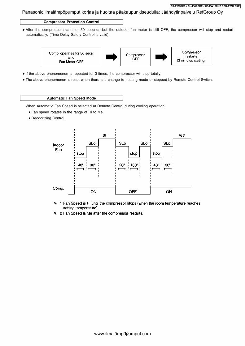
Compressor Protection Control
Automatic Fan Speed Mode
• • • • After the compressor starts for 50 seconds but the outdoor fan motor is still OFF, the compressor will stop and restartautomatically. (Time Delay Safety Control is valid).
• • • • If the above phenomenon is repeated for 3 times, the compressor will stop totally.
• • • • The above phenomenon is reset when there is a change to heating mode or stopped by Remote Control Switch.
When Automatic Fan Speed is selected at Remote Control during cooling operation.
• • • • Fan speed rotates in the range of Hi to Me.
• • • • Deodorizing Control.
15
CS-PW9CKE / CU-PW9CKE / CS-PW12CKE / CU-PW12CKE
Panasonic ilmalämpöpumput korjaa ja huoltaa pääkaupunkiseudulla: Jäähdytinpalvelu RefGroup Oy
www.ilmalämpöpumput.com
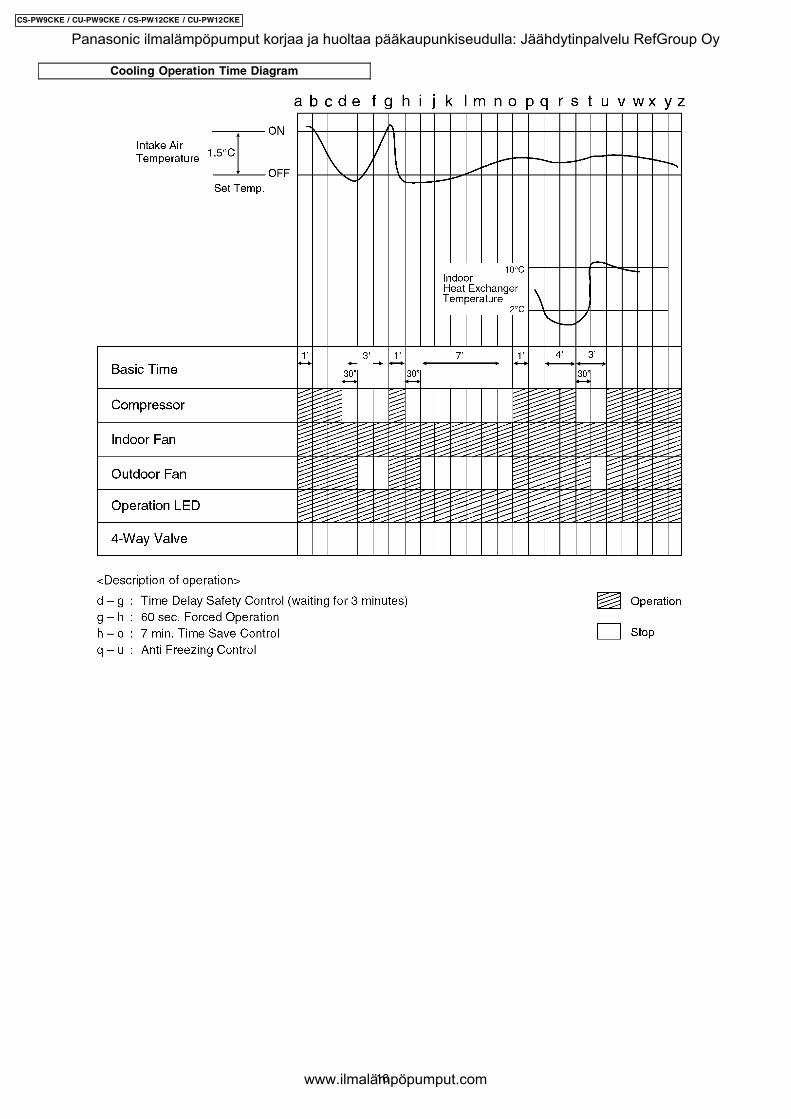
Cooling Operation Time Diagram
16
CS-PW9CKE / CU-PW9CKE / CS-PW12CKE / CU-PW12CKE
Panasonic ilmalämpöpumput korjaa ja huoltaa pääkaupunkiseudulla: Jäähdytinpalvelu RefGroup Oy
www.ilmalämpöpumput.com

Time Delay Safety Control
Starting Current Control
Anti-Freezing Control
Compressor Reverse Rotation Protection Control
Compressor Protection Control
Automatic Fan Speed Mode
7.2. Soft Dry Mode Operation
• • • • The unit starts cooling operation until the room temperature reaches the setting temperature set on the Remote Control, andthen Soft Dry operation will start.
• • • • During Soft Dry operation, the Indoor Fan will operate at Lo- speed.
• • • • The operation will be switched on and off for up to 10 minutes “ON” and 6 minutes “OFF”. Once Soft Dry operation is turnedoff, it stops for 6 minutes.
• • • • Once the compressor stops, it will not start for 3 minutes during Cooling operation.
• • • • Same as Starting Current Control for Cooling Mode operation.
• • • • Same as Anti-Freezing Control for Cooling Mode operation. (For Soft Dry region, 6 minutes waiting is valid during compressorstops.)
• • • • Same as Compressor Reverse Rotation Protection Control for Cooling Mode Operation. (For Soft Dry region, 6 minutes waitingis valid during compressor stops.)
• • • • Same as Compressor Protection Control for Cooling Mode Operation.
When Automatic Fan Speed is selected at Remote Control during Soft Dry operation.
• • • • Fan speed rotates at Lo- speed.
• • • • Deodorizing Control.
17
CS-PW9CKE / CU-PW9CKE / CS-PW12CKE / CU-PW12CKE
Panasonic ilmalämpöpumput korjaa ja huoltaa pääkaupunkiseudulla: Jäähdytinpalvelu RefGroup Oy
www.ilmalämpöpumput.com
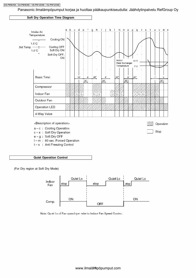
Soft Dry Operation Time Diagram
Quiet Operation Control
(For Dry region at Soft Dry Mode)
18
CS-PW9CKE / CU-PW9CKE / CS-PW12CKE / CU-PW12CKE
Panasonic ilmalämpöpumput korjaa ja huoltaa pääkaupunkiseudulla: Jäähdytinpalvelu RefGroup Oy
www.ilmalämpöpumput.com

Heating in operation according to Remote Control setting.
Time Delay Safety Control
30 minutes Time Save Control
Overload Protection Control
(b) Compressor high pressure protection
Compressor Reverse Rotation Protection Control
7.3. Heating Mode Operation
• • • • When the compressor is stopped by Remote Control, it restarts after 3 minutes when the Remote Control is turned ON.
• • • • When the setting temperature is reached during heating operation, the compressor stops and it will not start for 4 minutes.
• • • • The compressor will start automatically if it has stopped for 30 minutes even if the room temperature is between the compressorON temperature and OFF temperature.
(a) Outdoor Fan Control
• • • • If the temperature of the indoor heat exchanger rises to 51°C, Outdoor Fan stops.
The Outdoor Fan restarts when the indoor heat exchanger temperature falls to 49°C.
• • • • If the indoor heat exchanger becomes 65°C or more, the compressor will stop and restart automatically.
(Time Delay Safety Control - 4 minutes waiting).
• • • • If the compressor is operating continuously for 5 minutes or longer and temperature difference between intake air and indoorheat exchanger is 5°C or less for 2 minutes, compressor will stop and restart automatically.
(Time Delay Safety Control is valid).
! T = Indoor heat exchanger temperature - intake air temperature.This is to protect reverse rotation of the compressor when there is a instantaneous power failure.
19
CS-PW9CKE / CU-PW9CKE / CS-PW12CKE / CU-PW12CKE
Panasonic ilmalämpöpumput korjaa ja huoltaa pääkaupunkiseudulla: Jäähdytinpalvelu RefGroup Oy
www.ilmalämpöpumput.com
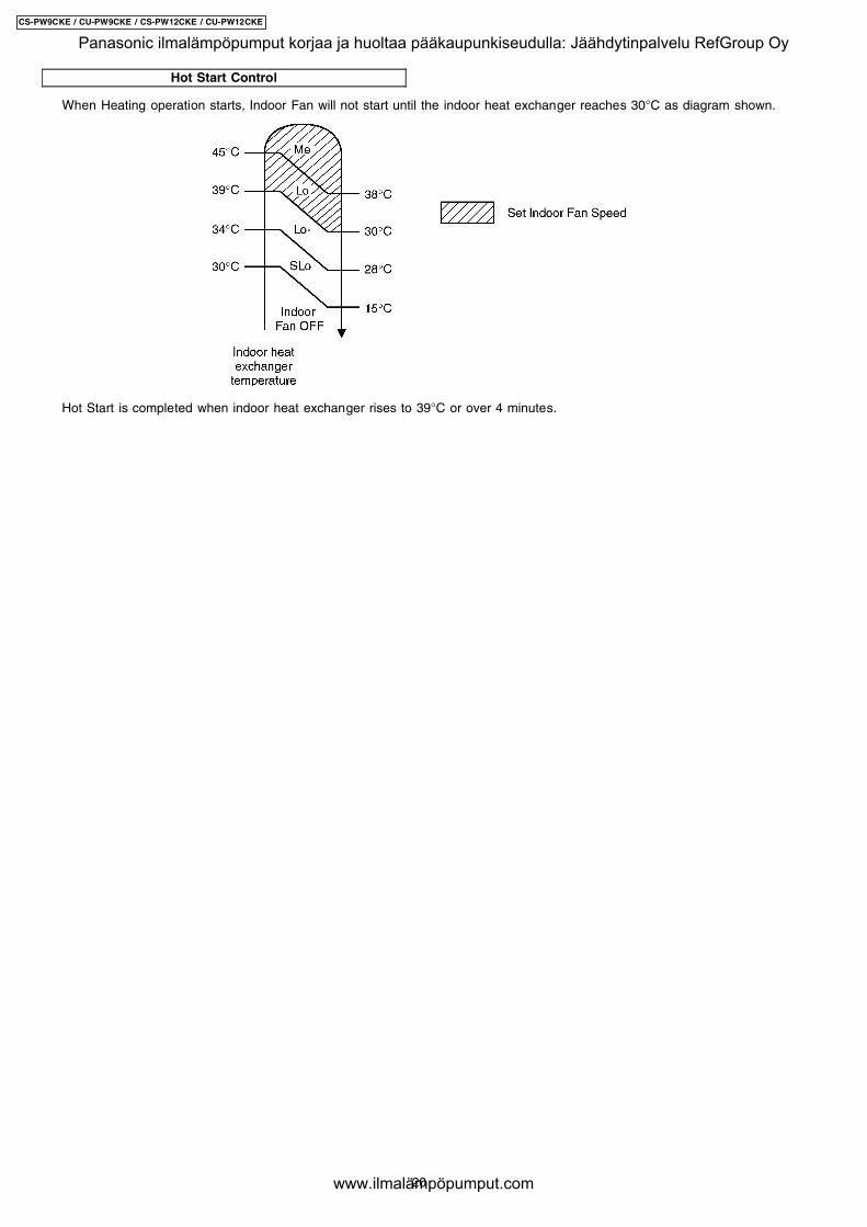
Hot Start Control
When Heating operation starts, Indoor Fan will not start until the indoor heat exchanger reaches 30°C as diagram shown.
Hot Start is completed when indoor heat exchanger rises to 39°C or over 4 minutes.
20
CS-PW9CKE / CU-PW9CKE / CS-PW12CKE / CU-PW12CKE
Panasonic ilmalämpöpumput korjaa ja huoltaa pääkaupunkiseudulla: Jäähdytinpalvelu RefGroup Oy
www.ilmalämpöpumput.com
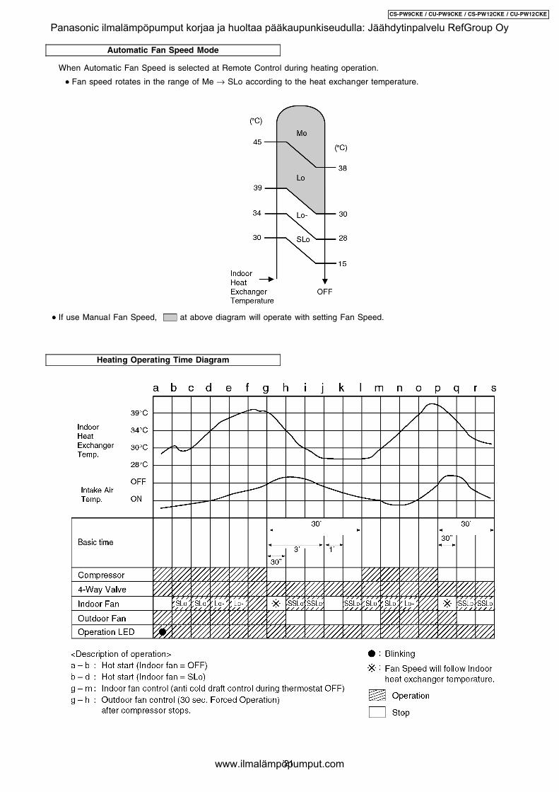
Automatic Fan Speed Mode
Heating Operating Time Diagram
When Automatic Fan Speed is selected at Remote Control during heating operation.
• • • • Fan speed rotates in the range of Me → SLo according to the heat exchanger temperature.
• • • • If use Manual Fan Speed, at above diagram will operate with setting Fan Speed.
21
CS-PW9CKE / CU-PW9CKE / CS-PW12CKE / CU-PW12CKE
Panasonic ilmalämpöpumput korjaa ja huoltaa pääkaupunkiseudulla: Jäähdytinpalvelu RefGroup Oy
www.ilmalämpöpumput.com
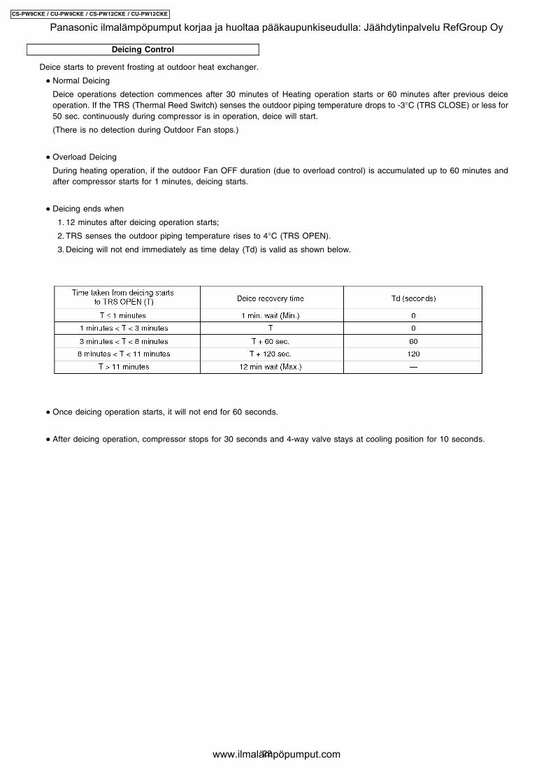
Deicing Control
Deice starts to prevent frosting at outdoor heat exchanger.
• • • • Normal Deicing
Deice operations detection commences after 30 minutes of Heating operation starts or 60 minutes after previous deiceoperation. If the TRS (Thermal Reed Switch) senses the outdoor piping temperature drops to -3°C (TRS CLOSE) or less for50 sec. continuously during compressor is in operation, deice will start.
(There is no detection during Outdoor Fan stops.)
• • • • Overload Deicing
During heating operation, if the outdoor Fan OFF duration (due to overload control) is accumulated up to 60 minutes andafter compressor starts for 1 minutes, deicing starts.
• • • • Deicing ends when
1. 12 minutes after deicing operation starts;
2. TRS senses the outdoor piping temperature rises to 4°C (TRS OPEN).
3. Deicing will not end immediately as time delay (Td) is valid as shown below.
• • • • Once deicing operation starts, it will not end for 60 seconds.
• • • • After deicing operation, compressor stops for 30 seconds and 4-way valve stays at cooling position for 10 seconds.
22
CS-PW9CKE / CU-PW9CKE / CS-PW12CKE / CU-PW12CKE
Panasonic ilmalämpöpumput korjaa ja huoltaa pääkaupunkiseudulla: Jäähdytinpalvelu RefGroup Oy
www.ilmalämpöpumput.com
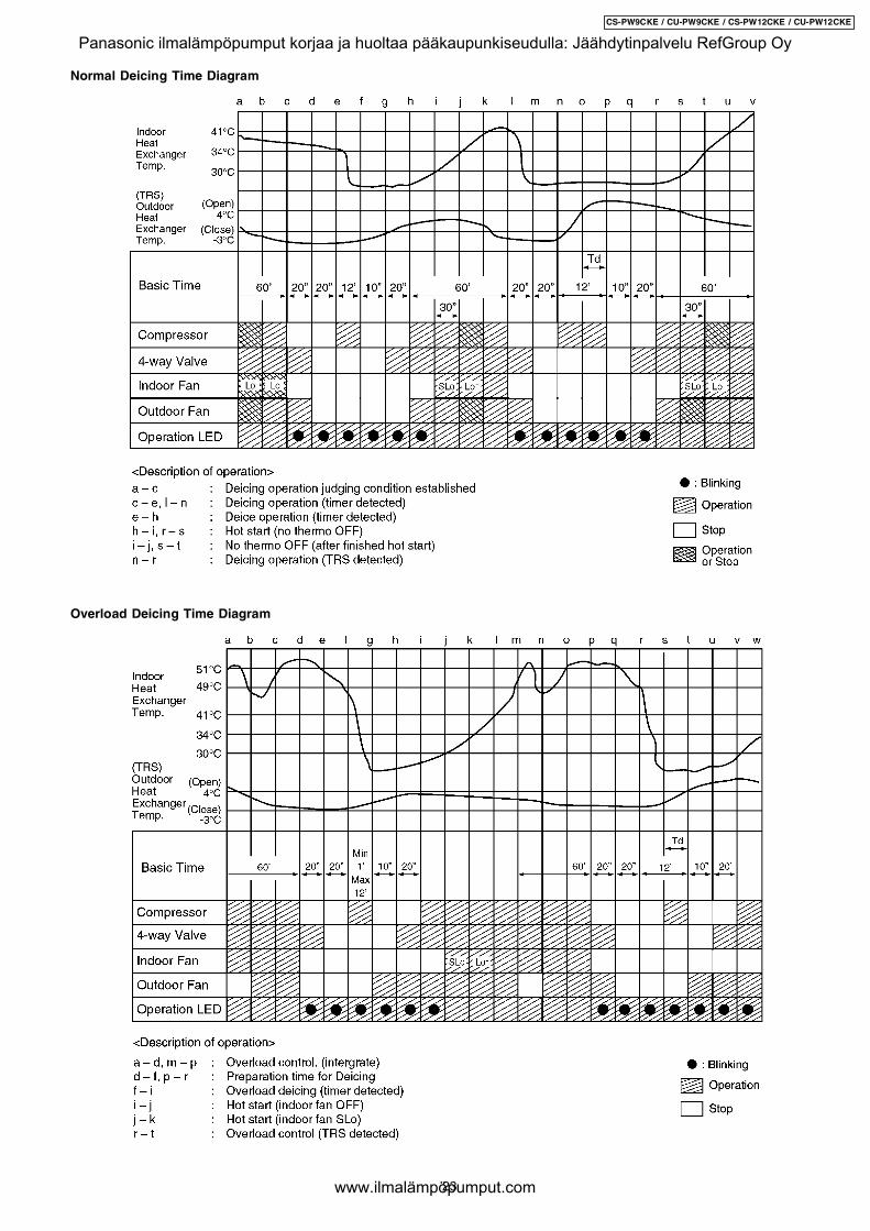
Normal Deicing Time Diagram
Overload Deicing Time Diagram
23
CS-PW9CKE / CU-PW9CKE / CS-PW12CKE / CU-PW12CKE
Panasonic ilmalämpöpumput korjaa ja huoltaa pääkaupunkiseudulla: Jäähdytinpalvelu RefGroup Oy
www.ilmalämpöpumput.com
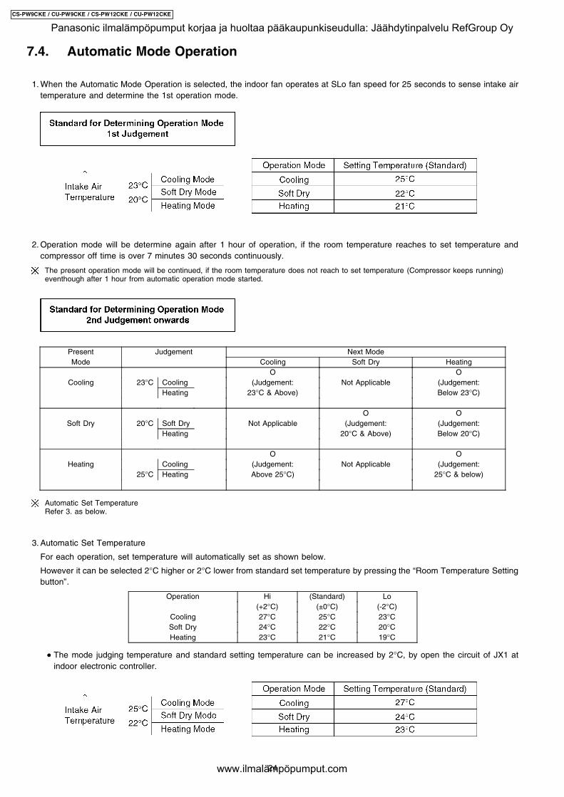
7.4. Automatic Mode Operation
1. When the Automatic Mode Operation is selected, the indoor fan operates at SLo fan speed for 25 seconds to sense intake airtemperature and determine the 1st operation mode.
2. Operation mode will be determine again after 1 hour of operation, if the room temperature reaches to set temperature andcompressor off time is over 7 minutes 30 seconds continuously.
The present operation mode will be continued, if the room temperature does not reach to set temperature (Compressor keeps running)eventhough after 1 hour from automatic operation mode started.
Present Judgement Next ModeMode Cooling Soft Dry Heating
O OCooling 23°C Cooling (Judgement: Not Applicable (Judgement:
Heating 23°C & Above) Below 23°C)
O OSoft Dry 20°C Soft Dry Not Applicable (Judgement: (Judgement:
Heating 20°C & Above) Below 20°C)
O OHeating Cooling (Judgement: Not Applicable (Judgement:
25°C Heating Above 25°C) 25°C & below)
Automatic Set TemperatureRefer 3. as below.
3. Automatic Set Temperature
For each operation, set temperature will automatically set as shown below.
However it can be selected 2°C higher or 2°C lower from standard set temperature by pressing the “Room Temperature Settingbutton”.
Operation Hi (Standard) Lo(+2°C) (±0°C) (-2°C)
Cooling 27°C 25°C 23°CSoft Dry 24°C 22°C 20°CHeating 23°C 21°C 19°C
• • • • The mode judging temperature and standard setting temperature can be increased by 2°C, by open the circuit of JX1 atindoor electronic controller.
24
CS-PW9CKE / CU-PW9CKE / CS-PW12CKE / CU-PW12CKE
Panasonic ilmalämpöpumput korjaa ja huoltaa pääkaupunkiseudulla: Jäähdytinpalvelu RefGroup Oy
www.ilmalämpöpumput.com
7.5. Random Auto Restart Control • • • • If there is a power failure during air conditioner operation, operation will be automatically restarted after 3 to 4 minutes when the
power is resumed. It will start with previous operation mode and airflow direction.
• • • • Restart time is decided randomly using 4 parameter:
Intake air temperature, setting temperature, fan speed and Air Swing Blade position.
• • • • Random Auto Restart Control is not available when Timer is set.
• • • • This control can be omitted by open the circuit of JX2. (Refer Circuit Diagram)
7.6. Delay ON Timer Control • • • • When the Delayed ON Timer is set by using the remote control, the unit will start operate slightly before the set time, so that
the room will reach nearly to the set temperature by the desired time.
• • • • For Cooling and Soft Dry mode, the operation will start 15 minutes before the set time.
• • • • For Heating mode, the operation will start 30 minutes before the set time.
• • • • For Automatic mode, the indoor fan will operate at SLo speed for 25 seconds, 30 minutes before the set time to detect theintake air temperature to determine the operation mode. The operation indication lamp will blink at this time.
7.7. Remote Control Signal Receiving Sound • • • • Long beep sound will be heard when:-
− − − − Stopping the Air Conditioner using ON/OFF switch.
• • • • Short beep sound will be heard for others.
• • • • To switch off the beep sound:-
Press the “Automatic Operation Button” continuously for 10 seconds or more (“beep” “beep” will be heard at the 10th second).
Repeat the above if you want to switch ON the beep sound.
However, if the “Automatic Operation Button” has been pressed the Automatic operation will be activated.If you do not require this operation, you may change it by using the remote control.
25
CS-PW9CKE / CU-PW9CKE / CS-PW12CKE / CU-PW12CKE
Panasonic ilmalämpöpumput korjaa ja huoltaa pääkaupunkiseudulla: Jäähdytinpalvelu RefGroup Oy
www.ilmalämpöpumput.com
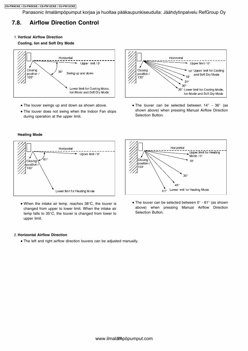
1. Vertical Airflow Direction
• • • • The louver swings up and down as shown above.
• • • • The louver does not swing when the Indoor Fan stopsduring operation at the upper limit.
Heating Mode
• • • • When the intake air temp. reaches 38°C, the louver ischanged from upper to lower limit. When the intake airtemp falls to 35°C, the louver is changed from lower toupper limit.
2. Horizontal Airflow Direction
• • • • The louver can be selected between 14° - 36° (asshown above) when pressing Manual Airflow DirectionSelection Button.
• • • • The louver can be selected between 0° - 61° (as shownabove) when pressing Manual Airflow DirectionSelection Button.
7.8. Airflow Direction Control
Cooling, Ion and Soft Dry Mode
• • • • The left and right airflow direction louvers can be adjusted manually.
26
CS-PW9CKE / CU-PW9CKE / CS-PW12CKE / CU-PW12CKE
Panasonic ilmalämpöpumput korjaa ja huoltaa pääkaupunkiseudulla: Jäähdytinpalvelu RefGroup Oy
www.ilmalämpöpumput.com

8 Installation InstructionsRequired tools for Installation Works
1. Philips screw driver 5. Spanner 9. Gas leak detector 13. Multimeter2. Level gauge 6. Pipe cutter 10. Measuring tape 14. Torque wrench
18 N.m (1.8 kgf.m)42 N.m (4.2 kgf.m)55 N.m (5.5 kgf.m)
3. Electric drill, hole core drill(ø70 mm)
7. Reamer 11. Thermometer 15. Vacuum pump
4. Hexagonal wrench (4 mm) 8. Knife 12. Megameter 16. Gauge manifold
8.1. Safety Precautions • • • • Read the following “SAFETY PRECAUTIONS” carefully before installation.
• • • • Electrical work must be installed by a licensed electrician. Be sure to use the correct rating of the power plug and main circuitfor the model to be installed.
• • • • The caution items stated here must be followed because these important contents are related to safety. The meaning of eachindication used is as below. Incorrect installation due to ignoring of the instruction will cause harm or damage, and theseriousness is classified by the following indications.
This indication shows the possibility of causing death or serious injury.
This indication shows the possibility of causing injury or damage to properties only.
The items to be followed are classified by the symbols:
Symbol with background white denotes item that is PROHIBITED from doing.
• • • • Carry out test running to confirm that no abnormality occurs after the installation. Then, explain to user the operation, care andmaintenance as stated in instructions. Please remind the customer to keep the operating instructions for future reference.
1. Engage dealer or specialist for installation. If installation done by the user is defective, it will cause water leakage, electrical shock or fire.2. Install according to this installation instruction strictly. If installation is defective, it will cause water leakage, electrical shock or fire.3. Use the attached accessories parts and specified parts for installation. Otherwise, it will cause the set to fall, water leakage, fire or
electrical shock.4. Install at a strong and firm location which is able to withstand the set’s weight. If the strength is not enough or installation is not properly
done, the set will drop and cause injury.5. For electrical work, follow the local national wiring standard, regulation and this installation instruction. An independent circuit and single
outlet must be used. If electrical circuit capacity is not enough or defect found in electrical work, it will cause electrical shock or fire.6. Use the specified cable (1.5 mm2) and connect tightly for indoor/outdoor connection. Connect tightly and clamp the cable so that no
external force will be acted on the terminal. If connection or fixing is not perfect, it will cause heat-up or fire at the connection.7. Wire routing must be properly arranged so that control board cover is fixed properly. If control board cover is not fixed perfectly, it will
cause heat-up at connection point of terminal, fire or electrical shock.8. When carrying out piping connection, take care not to let air substances other than the specified refrigerant go into refrigeration cycle.
Otherwise, it will cause lower capacity, abnormal high pressure in the refrigeration cycle, explosion and injury.9. When connecting the piping, do not allow air or any substances other than the specified refrigerant (R410A) to enter the
refrigeration cycle. Otherwise, this may lower the capacity, cause abnormally high pressure in the refrigeration cycle, andpossibly result in explosion and injury.
10. • • • • When connecting the piping, do not use any existing (R22) pipes and flare nuts. Using such same may causeabnormally high pressure in the refrigeration cycle (piping), and possibly result in explosion and injury. Use onlyR410A materials.
• • • • Thickness of copper pipes used with R410A must be more than 0.8 mm. Never use copper pipes thinner than 0.8mm.
• • • • It is desirable that the amount of residual oil is less than 40 mg/10 m.11. Do not modify the length of the power supply cord or use of the extension cord, and do not share the single outlet with
other electrical appliances. Otherwise, it will cause fire or electrical shock.
27
CS-PW9CKE / CU-PW9CKE / CS-PW12CKE / CU-PW12CKE
Panasonic ilmalämpöpumput korjaa ja huoltaa pääkaupunkiseudulla: Jäähdytinpalvelu RefGroup Oy
www.ilmalämpöpumput.com
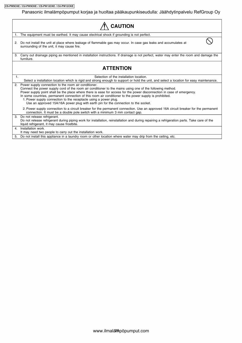
1. The equipment must be earthed. It may cause electrical shock if grounding is not perfect.
2. Do not install the unit at place where leakage of flammable gas may occur. In case gas leaks and accumulates atsurrounding of the unit, it may cause fire.
3. Carry out drainage piping as mentioned in installation instructions. If drainage is not perfect, water may enter the room and damage thefurniture.
1. Selection of the installation location.Select a installation location which is rigid and strong enough to support or hold the unit, and select a location for easy maintenance.
2. Power supply connection to the room air conditioner.Connect the power supply cord of the room air conditioner to the mains using one of the following method.Power supply point shall be the place where there is ease for access for the power disconnection in case of emergency.In some countries, permanent connection of this room air conditioner to the power supply is prohibited. 1. Power supply connection to the receptacle using a power plug.
Use an approved 15A/16A power plug with earth pin for the connection to the socket.
2. Power supply connection to a circuit breaker for the permanent connection. Use an approved 16A circuit breaker for the permanentconnection. It must be a double pole switch with a minimum 3 mm contact gap.
3. Do not release refrigerant.Do not release refrigerant during piping work for installation, reinstallation and during repairing a refrigeration parts. Take care of theliquid refrigerant, it may cause frostbite.
4. Installation work.It may need two people to carry out the installation work.
5. Do not install this appliance in a laundry room or other location where water may drip from the ceiling, etc.
28
CS-PW9CKE / CU-PW9CKE / CS-PW12CKE / CU-PW12CKE
Panasonic ilmalämpöpumput korjaa ja huoltaa pääkaupunkiseudulla: Jäähdytinpalvelu RefGroup Oy
www.ilmalämpöpumput.com
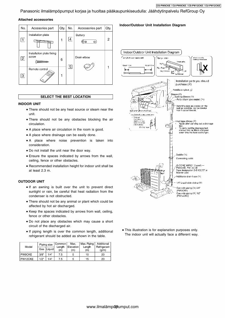
SELECT THE BEST LOCATION
INDOOR UNIT
• • • • There should not be any heat source or steam near theunit.
• • • • There should not be any obstacles blocking the aircirculation.
• • • • A place where air circulation in the room is good.
• • • • A place where drainage can be easily done.
• • • • A place where noise prevention is taken intoconsideration.
• • • • Do not install the unit near the door way.
• • • • Ensure the spaces indicated by arrows from the wall,ceiling, fence or other obstacles.
• • • • Recommended installation height for indoor unit shall beat least 2.3 m.
OUTDOOR UNIT
• • • • If an awning is built over the unit to prevent directsunlight or rain, be careful that heat radiation from thecondenser is not obstructed.
• • • • There should not be any animal or plant which could beaffected by hot air discharged.
• • • • Keep the spaces indicated by arrows from wall, ceiling,fence or other obstacles.
• • • • Do not place any obstacles which may cause a shortcircuit of the discharged air.
• • • • If piping length is over the common length, additionalrefrigerant should be added as shown in the table.
Indoor/Outdoor Unit Installation Diagram
• • • • This illustration is for explanation purposes only.The indoor unit will actually face a different way.
Attached accessories
29
CS-PW9CKE / CU-PW9CKE / CS-PW12CKE / CU-PW12CKE
Panasonic ilmalämpöpumput korjaa ja huoltaa pääkaupunkiseudulla: Jäähdytinpalvelu RefGroup Oy
www.ilmalämpöpumput.com
8.2.1. SELECT THE BEST LOCATION(Refer to “Select the best location”section)
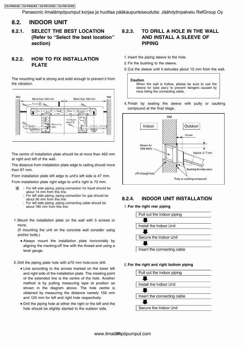
8.2.2. HOW TO FIX INSTALLATIONPLATE
The mounting wall is strong and solid enough to prevent it fromthe vibration.
The centre of installation plate should be at more than 450 mmat right and left of the wall.
The distance from installation plate edge to ceiling should morethan 67 mm.
From installation plate left edge to unit’s left side is 47 mm.
From installation plate right edge to unit’s right is 73 mm.
:
:
:
For left side piping, piping connection for liquid should beabout 14 mm from this line.For left side piping, piping connection for gas should beabout 56 mm from this line.For left side piping, piping connecting cable should beabout 785 mm from this line.
1. Mount the installation plate on the wall with 5 screws ormore.(If mounting the unit on the concrete wall consider usinganchor bolts.)
• • • • Always mount the installation plate horizontally byaligning the marking-off line with the thread and using alevel gauge.
2. Drill the piping plate hole with ø70 mm hole-core drill.
• • • • Line according to the arrows marked on the lower leftand right side of the installation plate. The meeting pointof the extended line is the centre of the hole. Anothermethod is by putting measuring tape at position asshown in the diagram above. The hole centre isobtained by measuring the distance namely 150 mmand 125 mm for left and right hole respectively.
• • • • Drill the piping hole at either the right or the left and thehole should be slightly slanted to the outdoor side.
8.2.3. TO DRILL A HOLE IN THE WALLAND INSTALL A SLEEVE OFPIPING
1. Insert the piping sleeve to the hole.
2. Fix the bushing to the sleeve.
3. Cut the sleeve until it extrudes about 15 mm from the wall.
CautionWhen the wall is hollow, please be sure to use thesleeve for tube ass’y to prevent dangers caused bymice biting the connecting cable.
4. Finish by sealing the sleeve with putty or caulkingcompound at the final stage.
8.2.4. INDOOR UNIT INSTALLATION
1. For the right rear piping
2. For the right and right bottom piping
8.2. INDOOR UNIT
30
CS-PW9CKE / CU-PW9CKE / CS-PW12CKE / CU-PW12CKE
Panasonic ilmalämpöpumput korjaa ja huoltaa pääkaupunkiseudulla: Jäähdytinpalvelu RefGroup Oy
www.ilmalämpöpumput.com
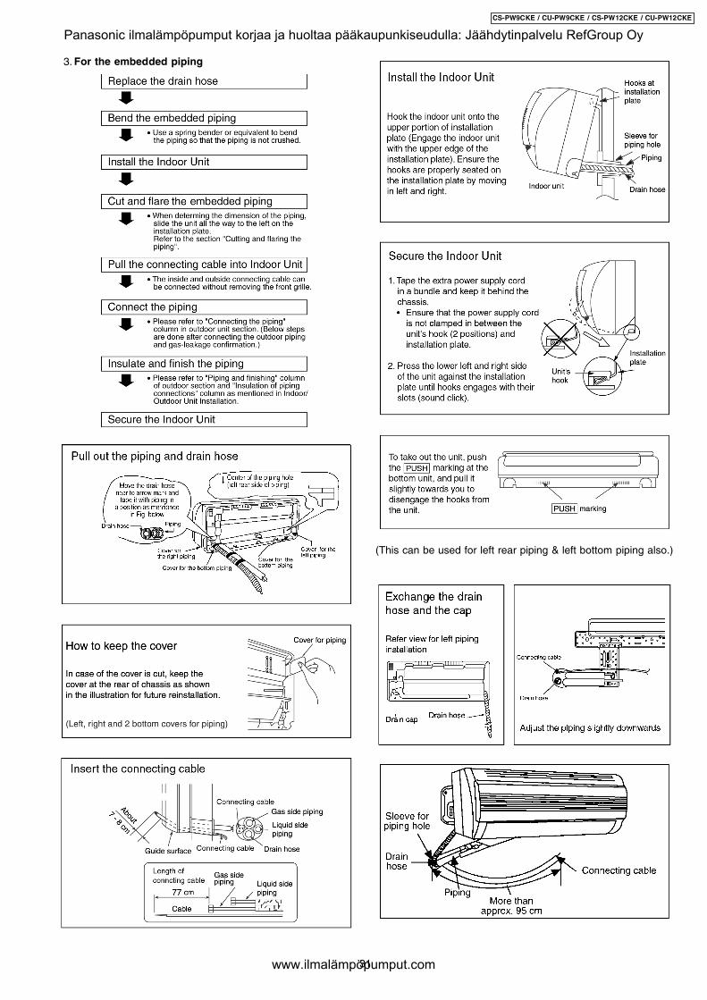
3. For the embedded piping
(This can be used for left rear piping & left bottom piping also.)
31
CS-PW9CKE / CU-PW9CKE / CS-PW12CKE / CU-PW12CKE
Panasonic ilmalämpöpumput korjaa ja huoltaa pääkaupunkiseudulla: Jäähdytinpalvelu RefGroup Oy
www.ilmalämpöpumput.com
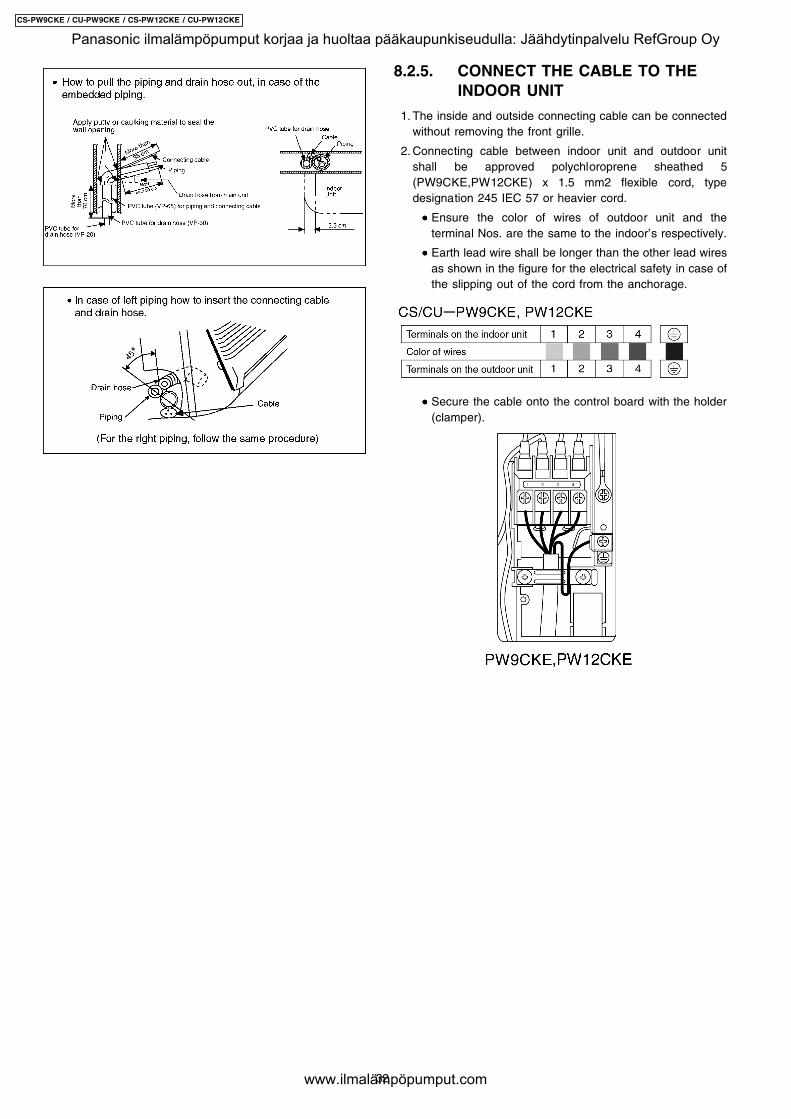
8.2.5. CONNECT THE CABLE TO THEINDOOR UNIT
1. The inside and outside connecting cable can be connectedwithout removing the front grille.
2. Connecting cable between indoor unit and outdoor unitshall be approved polychloroprene sheathed 5(PW9CKE,PW12CKE) x 1.5 mm2 flexible cord, typedesignation 245 IEC 57 or heavier cord.
• • • • Ensure the color of wires of outdoor unit and theterminal Nos. are the same to the indoor’s respectively.
• • • • Earth lead wire shall be longer than the other lead wiresas shown in the figure for the electrical safety in case ofthe slipping out of the cord from the anchorage.
• • • • Secure the cable onto the control board with the holder(clamper).
32
CS-PW9CKE / CU-PW9CKE / CS-PW12CKE / CU-PW12CKE
Panasonic ilmalämpöpumput korjaa ja huoltaa pääkaupunkiseudulla: Jäähdytinpalvelu RefGroup Oy
www.ilmalämpöpumput.com
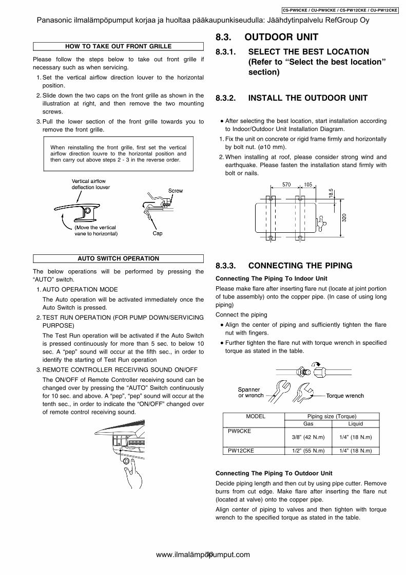
HOW TO TAKE OUT FRONT GRILLE
Please follow the steps below to take out front grille ifnecessary such as when servicing.
1. Set the vertical airflow direction louver to the horizontalposition.
2. Slide down the two caps on the front grille as shown in theillustration at right, and then remove the two mountingscrews.
3. Pull the lower section of the front grille towards you toremove the front grille.
When reinstalling the front grille, first set the verticalairflow direction louvre to the horizontal position andthen carry out above steps 2 - 3 in the reverse order.
AUTO SWITCH OPERATION
The below operations will be performed by pressing the“AUTO” switch.
1. AUTO OPERATION MODE
The Auto operation will be activated immediately once theAuto Switch is pressed.
2. TEST RUN OPERATION (FOR PUMP DOWN/SERVICINGPURPOSE)
The Test Run operation will be activated if the Auto Switchis pressed continuously for more than 5 sec. to below 10sec. A “pep” sound will occur at the fifth sec., in order toidentify the starting of Test Run operation
3. REMOTE CONTROLLER RECEIVING SOUND ON/OFF
The ON/OFF of Remote Controller receiving sound can bechanged over by pressing the “AUTO” Switch continuouslyfor 10 sec. and above. A “pep”, “pep” sound will occur at thetenth sec., in order to indicate the “ON/OFF” changed overof remote control receiving sound.
8.3. OUTDOOR UNIT
8.3.1. SELECT THE BEST LOCATION(Refer to “Select the best location”section)
8.3.2. INSTALL THE OUTDOOR UNIT
• • • • After selecting the best location, start installation accordingto Indoor/Outdoor Unit Installation Diagram.
1. Fix the unit on concrete or rigid frame firmly and horizontallyby bolt nut. (ø10 mm).
2. When installing at roof, please consider strong wind andearthquake. Please fasten the installation stand firmly withbolt or nails.
8.3.3. CONNECTING THE PIPING
Connecting The Piping To Indoor Unit
Please make flare after inserting flare nut (locate at joint portionof tube assembly) onto the copper pipe. (In case of using longpiping)
Connect the piping
• • • • Align the center of piping and sufficiently tighten the flarenut with fingers.
• • • • Further tighten the flare nut with torque wrench in specifiedtorque as stated in the table.
MODEL Piping size (Torque)Gas Liquid
PW9CKE3/8” (42 N.m) 1/4” (18 N.m)
PW12CKE 1/2” (55 N.m) 1/4” (18 N.m)
Connecting The Piping To Outdoor Unit
Decide piping length and then cut by using pipe cutter. Removeburrs from cut edge. Make flare after inserting the flare nut(located at valve) onto the copper pipe.
Align center of piping to valves and then tighten with torquewrench to the specified torque as stated in the table.
33
CS-PW9CKE / CU-PW9CKE / CS-PW12CKE / CU-PW12CKE
Panasonic ilmalämpöpumput korjaa ja huoltaa pääkaupunkiseudulla: Jäähdytinpalvelu RefGroup Oy
www.ilmalämpöpumput.com
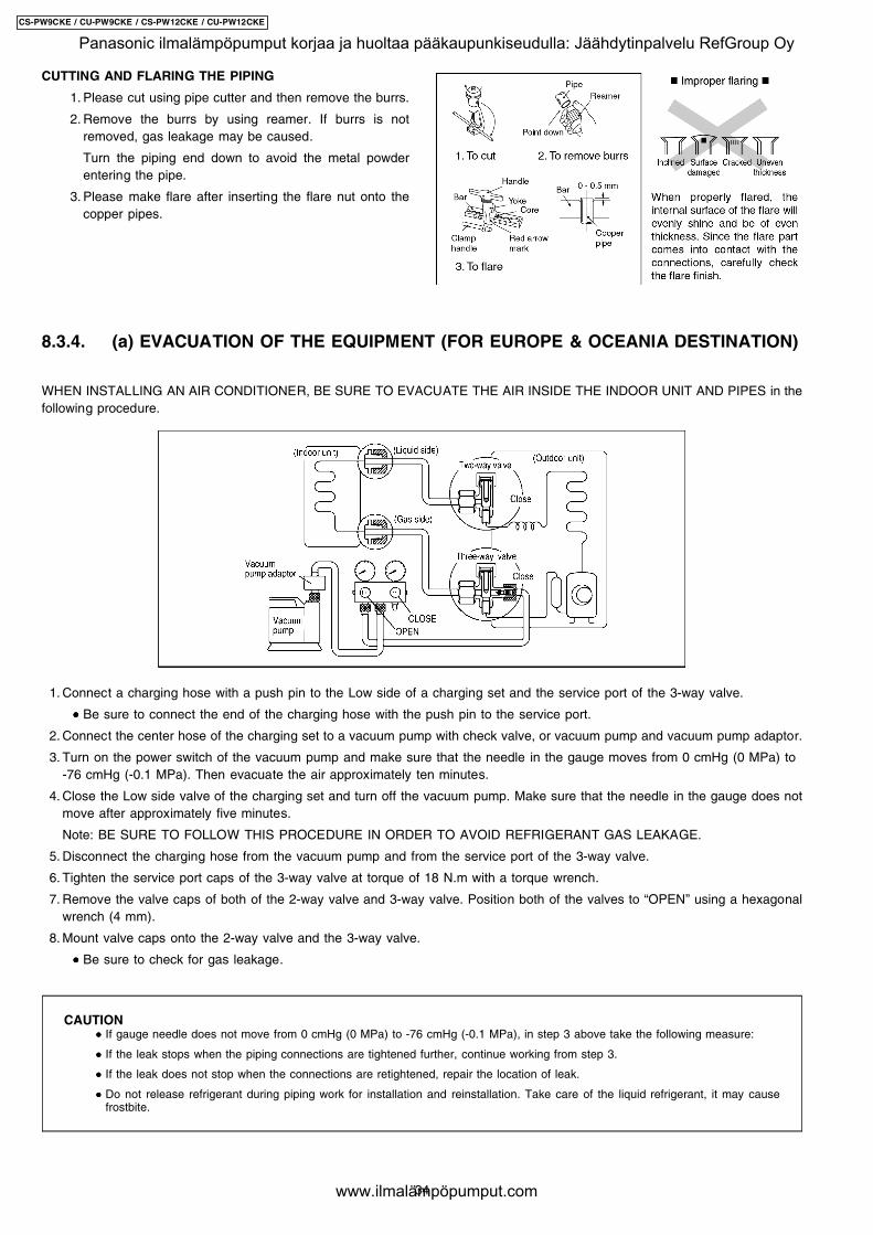
CUTTING AND FLARING THE PIPING
1. Please cut using pipe cutter and then remove the burrs.
2. Remove the burrs by using reamer. If burrs is notremoved, gas leakage may be caused.
Turn the piping end down to avoid the metal powderentering the pipe.
3. Please make flare after inserting the flare nut onto thecopper pipes.
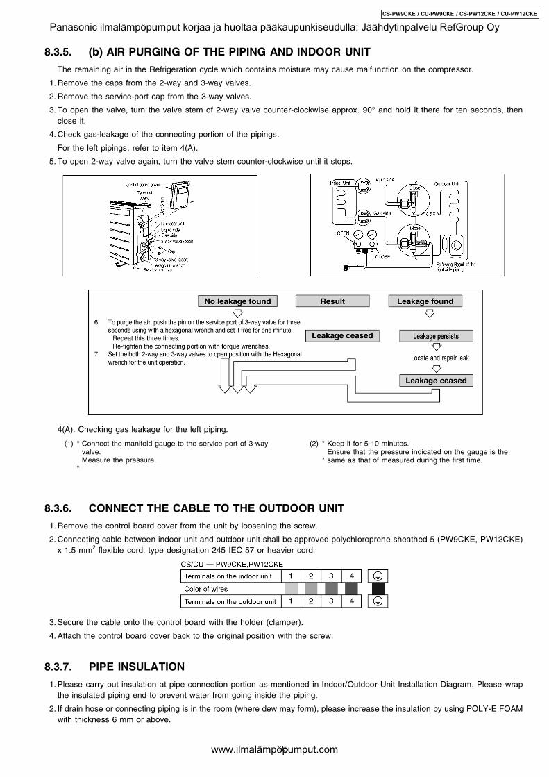
8.3.4. (a) EVACUATION OF THE EQUIPMENT (FOR EUROPE & OCEANIA DESTINATION)
WHEN INSTALLING AN AIR CONDITIONER, BE SURE TO EVACUATE THE AIR INSIDE THE INDOOR UNIT AND PIPES in thefollowing procedure.
1. Connect a charging hose with a push pin to the Low side of a charging set and the service port of the 3-way valve.
• • • • Be sure to connect the end of the charging hose with the push pin to the service port.
2. Connect the center hose of the charging set to a vacuum pump with check valve, or vacuum pump and vacuum pump adaptor.
3. Turn on the power switch of the vacuum pump and make sure that the needle in the gauge moves from 0 cmHg (0 MPa) to-76 cmHg (-0.1 MPa). Then evacuate the air approximately ten minutes.
4. Close the Low side valve of the charging set and turn off the vacuum pump. Make sure that the needle in the gauge does notmove after approximately five minutes.
Note: BE SURE TO FOLLOW THIS PROCEDURE IN ORDER TO AVOID REFRIGERANT GAS LEAKAGE.
5. Disconnect the charging hose from the vacuum pump and from the service port of the 3-way valve.
6. Tighten the service port caps of the 3-way valve at torque of 18 N.m with a torque wrench.
7. Remove the valve caps of both of the 2-way valve and 3-way valve. Position both of the valves to “OPEN” using a hexagonalwrench (4 mm).
8. Mount valve caps onto the 2-way valve and the 3-way valve.
• • • • Be sure to check for gas leakage.
CAUTION • • • • If gauge needle does not move from 0 cmHg (0 MPa) to -76 cmHg (-0.1 MPa), in step 3 above take the following measure:
• • • • If the leak stops when the piping connections are tightened further, continue working from step 3.
• • • • If the leak does not stop when the connections are retightened, repair the location of leak.
• • • • Do not release refrigerant during piping work for installation and reinstallation. Take care of the liquid refrigerant, it may causefrostbite.
34
CS-PW9CKE / CU-PW9CKE / CS-PW12CKE / CU-PW12CKE
Panasonic ilmalämpöpumput korjaa ja huoltaa pääkaupunkiseudulla: Jäähdytinpalvelu RefGroup Oy
www.ilmalämpöpumput.com
(1) *
*
Connect the manifold gauge to the service port of 3-wayvalve.Measure the pressure.
(2) *
*
Keep it for 5-10 minutes.Ensure that the pressure indicated on the gauge is thesame as that of measured during the first time.
8.3.5. (b) AIR PURGING OF THE PIPING AND INDOOR UNIT
The remaining air in the Refrigeration cycle which contains moisture may cause malfunction on the compressor.
1. Remove the caps from the 2-way and 3-way valves.
2. Remove the service-port cap from the 3-way valves.
3. To open the valve, turn the valve stem of 2-way valve counter-clockwise approx. 90° and hold it there for ten seconds, thenclose it.
4. Check gas-leakage of the connecting portion of the pipings.
For the left pipings, refer to item 4(A).
5. To open 2-way valve again, turn the valve stem counter-clockwise until it stops.
4(A). Checking gas leakage for the left piping.
8.3.6. CONNECT THE CABLE TO THE OUTDOOR UNIT
1. Remove the control board cover from the unit by loosening the screw.
2. Connecting cable between indoor unit and outdoor unit shall be approved polychloroprene sheathed 5 (PW9CKE, PW12CKE)x 1.5 mm2 flexible cord, type designation 245 IEC 57 or heavier cord.
3. Secure the cable onto the control board with the holder (clamper).
4. Attach the control board cover back to the original position with the screw.
8.3.7. PIPE INSULATION
1. Please carry out insulation at pipe connection portion as mentioned in Indoor/Outdoor Unit Installation Diagram. Please wrapthe insulated piping end to prevent water from going inside the piping.
2. If drain hose or connecting piping is in the room (where dew may form), please increase the insulation by using POLY-E FOAMwith thickness 6 mm or above.
35
CS-PW9CKE / CU-PW9CKE / CS-PW12CKE / CU-PW12CKE
Panasonic ilmalämpöpumput korjaa ja huoltaa pääkaupunkiseudulla: Jäähdytinpalvelu RefGroup Oy
www.ilmalämpöpumput.com
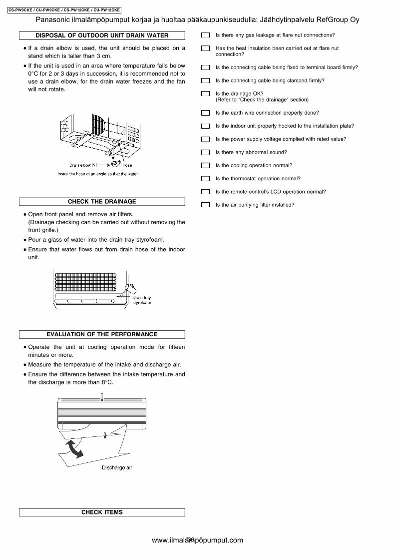
DISPOSAL OF OUTDOOR UNIT DRAIN WATER
• • • • If a drain elbow is used, the unit should be placed on astand which is taller than 3 cm.
• • • • If the unit is used in an area where temperature falls below0°C for 2 or 3 days in succession, it is recommended not touse a drain elbow, for the drain water freezes and the fanwill not rotate.
CHECK THE DRAINAGE
• • • • Open front panel and remove air filters.(Drainage checking can be carried out without removing thefront grille.)
• • • • Pour a glass of water into the drain tray-styrofoam.
• • • • Ensure that water flows out from drain hose of the indoorunit.
EVALUATION OF THE PERFORMANCE
• • • • Operate the unit at cooling operation mode for fifteenminutes or more.
• • • • Measure the temperature of the intake and discharge air.
• • • • Ensure the difference between the intake temperature andthe discharge is more than 8°C.
CHECK ITEMS
Is there any gas leakage at flare nut connections?
Has the heat insulation been carried out at flare nutconnection?
Is the connecting cable being fixed to terminal board firmly?
Is the connecting cable being clamped firmly?
Is the drainage OK?(Refer to “Check the drainage” section)
Is the earth wire connection properly done?
Is the indoor unit properly hooked to the installation plate?
Is the power supply voltage complied with rated value?
Is there any abnormal sound?
Is the cooling operation normal?
Is the thermostat operation normal?
Is the remote control’s LCD operation normal?
Is the air purifying filter installed?
36
CS-PW9CKE / CU-PW9CKE / CS-PW12CKE / CU-PW12CKE
Panasonic ilmalämpöpumput korjaa ja huoltaa pääkaupunkiseudulla: Jäähdytinpalvelu RefGroup Oy
www.ilmalämpöpumput.com
9 Installation and Servicing Air Conditioner Using R410A
9.1. OUTLINE
9.1.1. About R410A Refrigerant
1. Converting air conditioners to R410ASince it was declared in1974 that chlorofluorocarbons (CFC), hydro chlorofluorocarbons (HCFC) and other substances pose adestructive danger to the ozone layer in the earth´s upper stratosphere (20 to 40 km above the earth), measures have beentaken around the world to prevent this destruction.The R22 refrigerant which has conventionally been used in ACs is an HCFC refrigerant and, therefore, possesses this ozone-destroying potential. International regulations (the Montreal Protocol Ozone-Damaging Substances) and the domestic laws ofvarious countries call for the early substitution of R22 by a refrigerant which will not harm the ozone layer.
• • • • In ACs, the HFC refrigerant which has become the mainstream alternative called R410A.Compared with R22, the pressureof R410A is approximately 1.6 times as high at the same refrigerant temperature, but the energy efficiency is about thesame. Consisting of hydrogen (H), fluorine (F) and carbon (C), R410A is an HFC refrigerant. Another typical HFC refrigerantis R407C. While the energy efficiency of R407C is some what inferior to that of R410A, it offers the advantage of havingpressure characteristics which are about the same as those of R22, and is used mainly in packaged ACs.
2. The characteristics of HFC (R410A) refrigerants
a. Chemical characteristicsThe chemical characteristics of R410A are similar to those of R22 in that both are chemically stable, non-flammablerefrigerants with low toxicity.However, just like R22, the specific gravity of R410A gas is heavier than that of air. Because of this, it can cause an oxygendeficiency if it leaks into a closed room since it collects in the lower area of the room. It also generates toxic gas when it isdirectly exposed to a flame, so it must be used in a well ventilated environment where it will not collect.
Table 1 Physical comparison of R410A and R22R410A R22
Composition (wt%) R32/R125 (50/50) R22 (100)Boiling point (°C) -51.4 -40.8Vaporizing pressure (25°C) 1.56 Mpa (15.9 kgf/cm2) 0.94 Mpa (9.6 kgf/cm2)Saturated vapor density 64.0 kg/m3 44.4 kg/m3
Flammability Non-flammable Non-flammableOzone-destroying point (ODP) 0 0.005Global-warming point (GWP) 1730 1700
b. Compositional change (pseudo-azeotropic characteristics)R410A is a pseudo-azeotropic mixture comprising the two components R32 and R125. Multi-component refrigerants withthese chemical characteristics exhibit little compositional change even from phase changes due to vaporization 9orcondensation), which means that there is little change in the circulating refrigerant composition even when the refrigerantleaks from the gaseous section of the piping.Accordingly, R410A can be handled in almost the same manner as the single-component refrigerant R22. However, whencharging, because there is a slight change in composition between the gas phase and the liquid phase inside a cylinder orother container, charging should basically begin with the liquid side.
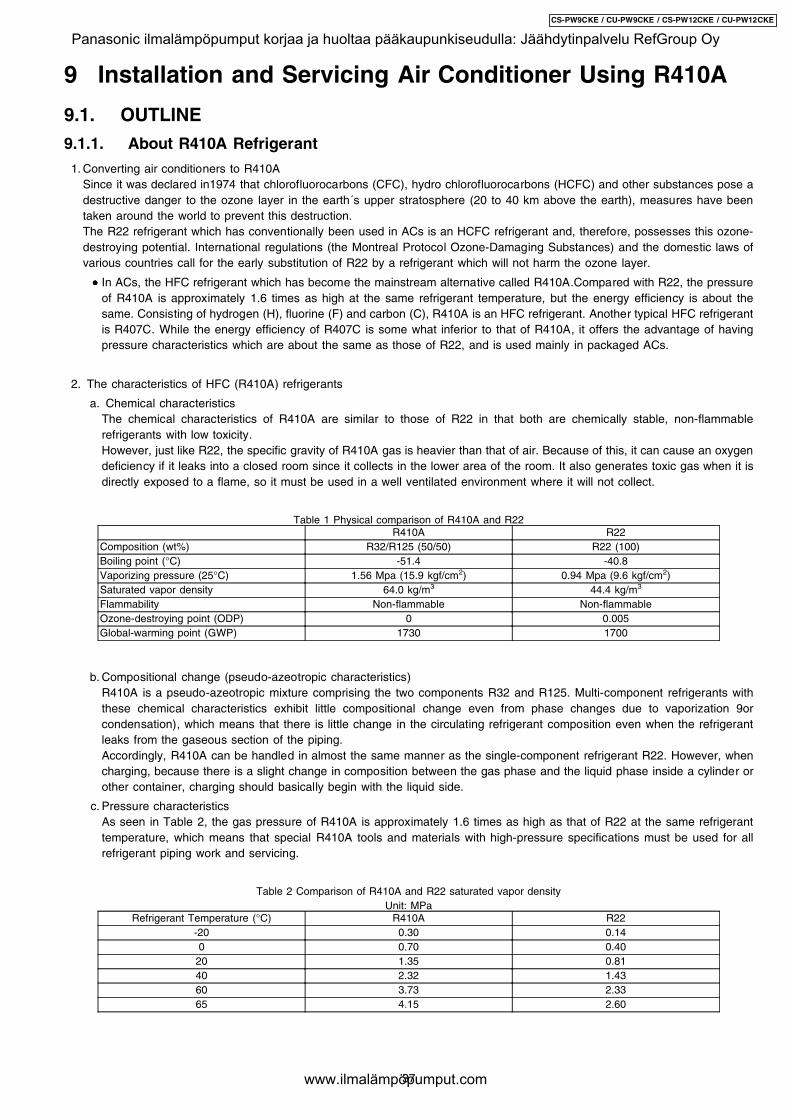
c. Pressure characteristicsAs seen in Table 2, the gas pressure of R410A is approximately 1.6 times as high as that of R22 at the same refrigeranttemperature, which means that special R410A tools and materials with high-pressure specifications must be used for allrefrigerant piping work and servicing.
Table 2 Comparison of R410A and R22 saturated vapor densityUnit: MPa
Refrigerant Temperature (°C) R410A R22-20 0.30 0.140 0.70 0.40
20 1.35 0.8140 2.32 1.4360 3.73 2.3365 4.15 2.60
37
CS-PW9CKE / CU-PW9CKE / CS-PW12CKE / CU-PW12CKE
Panasonic ilmalämpöpumput korjaa ja huoltaa pääkaupunkiseudulla: Jäähdytinpalvelu RefGroup Oy
www.ilmalämpöpumput.com

d. R410A refrigerating machine oilConventionally, mineral oil or a synthetic oil such as alkylbenzene has been used for R22 refrigerating machine oil. Becauseof the poor compatibility between R410A and conventional oils like mineral oil, however, there is a tendency for therefrigerating machine oil to collect in the refrigerating cycle. For this reason, polyester and other synthetic oils which havea high compatibility with R410A are used as refrigerating machine oil.Because of the high hygroscopic property of synthetic oil, more care must be taken in its handling than was necessary withconventional refrigerating machine oils. Also, these synthetic oils will degrade if mixed with mineral oil or alkylbenzene,causing clogging in capillary tubes or compressor malfunction. Do not mix them under any circumstances.
9.1.2. Safety Measure When Installing / Receiving Refrigerant Piping
Cause the gas pressure of R410A is approximately 1.6 times as high as that of R22, a mistake in installation or servicing couldresult in a major accident. It is essential that you use R410a tools and materials, and that you observe the following precautionsto ensure safety.
1. Do not use any refrigerant other than R410A in ACs that have been used with R410A.
2. If any refrigerant gas leaks while you are working, ventilate the room. Toxic gas may be generated if refrigerant gas is exposedto a direct flame.
3. When installing or transferring an AC, do not allow any air or substance other than R410A to mix into the refrigeration cycle. Ifit does, the pressure in the refrigeration cycle can become abnormally high, possibly causing an explosion and/or injury.
4. After finishing the installation, check to make sure there is no refrigerant gas leaking.
5. When installing or transferring an AC, follow the instructions in the installation instructions carefully. Incorrect installation canresult in an abnormal refrigeration cycle or water leakage, electric shock, fire, etc.
6. Do not perform any alterations on the AC unit under any circumstances. Have all repair work done by a specialist. Incorrectrepairs can result in an water leakage, electric shock, fire, etc.
9.2. TOOL FOR INSTALLING / SERVICING REFRIGERANT PIPING
9.2.1. Necessary Tools
In order to prevent an R410A AC from mistakenly being charged with any other refrigerant, the diameter of the 3-way valve serviceport on the outdoor unit has been changed. Also, to increase its ability to withstand pressure, the opposing dimensions have beenchanged for the refrigerant pipe flaring size and flare nut. Accordingly, when installing or servicing refrigerant piping, you must haveboth the R410A and ordinary tools listed below.
Table 3 Tools for installation, transferring or replacementType of work Ordinary tools R410A tools
Flaring Flaring tool (clutch type), pipe cutter,reamer
Copper pipe gauge for clearanceAdjustment, flaring tool (clutch type)*1)
Bending, connecting pipes Torque wrench (nominal diameter 1/4,3/8,1/2) Fixed spanner (opposing sides 12mm, 17 mm, 19 mm) Adjustable wrench,Spring bender
Air purging Vacuum pump Hexagonal wrench(opposing sides 4 mm)
Manifold gauge, charging hose, vacuumpump adaptor
Gas leak inspection Gas leak inspection fluid or soapy water Electric gas leak detector for HFCrefrigerant*2)
*1) You can use the conventional (R22) flaring tool. If you need to buy a new tool, buy the R410A type.
*2) Use when it is necessary to detect small gas leaks.
For other installation work, you should have the usual tools, such as screwdrivers (+,-), a metal-cutting saw, an electrical drill, a holecore drill (65 or 70 dia.), a tape measure, a level, a thermometer, a clamp meter, an insulation tester, a voltmeter, etc.
Table 4 Tools for servingType of work Ordinary tools R410A tools
Refrigerant charging Electronic scale for refrigerant chargingRefrigerant cylinder Charging orifice andpacking for refrigerant cylinder
Brazing (Replacing refrigerating cyclepart*1)
Nitrogen blow set (be sure to use nitrogenblowing for all brazing), and brazing), andbrazing machine
*1) Always replace the dryer of the outdoor unit at the same time. The replacement dryer is wrapped in a vacuum pack. Replaceit last among the refrigerating cycle parts. Start brazing as soon as you have opened the vacuum pack, and begin the vacuumingoperation within 2 hours.
38
CS-PW9CKE / CU-PW9CKE / CS-PW12CKE / CU-PW12CKE
Panasonic ilmalämpöpumput korjaa ja huoltaa pääkaupunkiseudulla: Jäähdytinpalvelu RefGroup Oy
www.ilmalämpöpumput.com
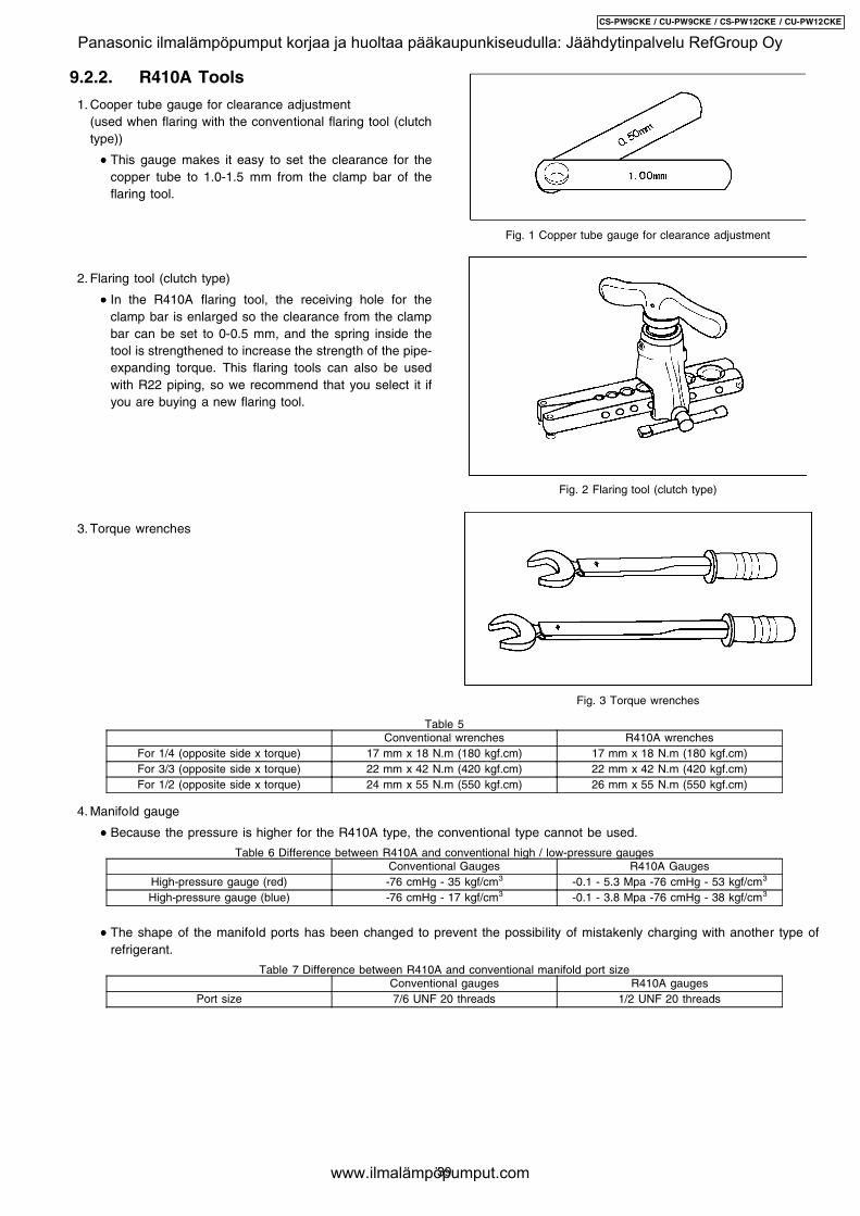
9.2.2. R410A Tools
1. Cooper tube gauge for clearance adjustment(used when flaring with the conventional flaring tool (clutchtype))
• • • • This gauge makes it easy to set the clearance for thecopper tube to 1.0-1.5 mm from the clamp bar of theflaring tool.
2. Flaring tool (clutch type)
• • • • In the R410A flaring tool, the receiving hole for theclamp bar is enlarged so the clearance from the clampbar can be set to 0-0.5 mm, and the spring inside thetool is strengthened to increase the strength of the pipe-expanding torque. This flaring tools can also be usedwith R22 piping, so we recommend that you select it ifyou are buying a new flaring tool.
3. Torque wrenches
4. Manifold gauge
Fig. 1 Copper tube gauge for clearance adjustment
Fig. 2 Flaring tool (clutch type)
Fig. 3 Torque wrenches
Table 5Conventional wrenches R410A wrenches
For 1/4 (opposite side x torque) 17 mm x 18 N.m (180 kgf.cm) 17 mm x 18 N.m (180 kgf.cm)For 3/3 (opposite side x torque) 22 mm x 42 N.m (420 kgf.cm) 22 mm x 42 N.m (420 kgf.cm)For 1/2 (opposite side x torque) 24 mm x 55 N.m (550 kgf.cm) 26 mm x 55 N.m (550 kgf.cm)
• • • • Because the pressure is higher for the R410A type, the conventional type cannot be used.
Table 6 Difference between R410A and conventional high / low-pressure gaugesConventional Gauges R410A Gauges
High-pressure gauge (red) -76 cmHg - 35 kgf/cm3 -0.1 - 5.3 Mpa -76 cmHg - 53 kgf/cm3
High-pressure gauge (blue) -76 cmHg - 17 kgf/cm3 -0.1 - 3.8 Mpa -76 cmHg - 38 kgf/cm3
• • • • The shape of the manifold ports has been changed to prevent the possibility of mistakenly charging with another type ofrefrigerant.
Table 7 Difference between R410A and conventional manifold port sizeConventional gauges R410A gauges
Port size 7/6 UNF 20 threads 1/2 UNF 20 threads
39
CS-PW9CKE / CU-PW9CKE / CS-PW12CKE / CU-PW12CKE
Panasonic ilmalämpöpumput korjaa ja huoltaa pääkaupunkiseudulla: Jäähdytinpalvelu RefGroup Oy
www.ilmalämpöpumput.com
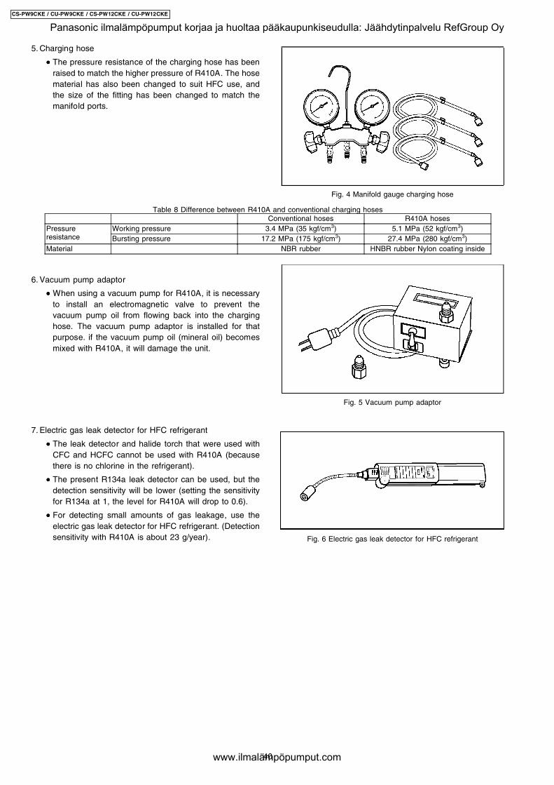
5. Charging hose
• • • • The pressure resistance of the charging hose has beenraised to match the higher pressure of R410A. The hosematerial has also been changed to suit HFC use, andthe size of the fitting has been changed to match themanifold ports.
6. Vacuum pump adaptor
• • • • When using a vacuum pump for R410A, it is necessaryto install an electromagnetic valve to prevent thevacuum pump oil from flowing back into the charginghose. The vacuum pump adaptor is installed for thatpurpose. if the vacuum pump oil (mineral oil) becomesmixed with R410A, it will damage the unit.
7. Electric gas leak detector for HFC refrigerant
• • • • The leak detector and halide torch that were used withCFC and HCFC cannot be used with R410A (becausethere is no chlorine in the refrigerant).
• • • • The present R134a leak detector can be used, but thedetection sensitivity will be lower (setting the sensitivityfor R134a at 1, the level for R410A will drop to 0.6).
• • • • For detecting small amounts of gas leakage, use theelectric gas leak detector for HFC refrigerant. (Detectionsensitivity with R410A is about 23 g/year).
Fig. 4 Manifold gauge charging hose
Fig. 5 Vacuum pump adaptor
Fig. 6 Electric gas leak detector for HFC refrigerant
Table 8 Difference between R410A and conventional charging hosesConventional hoses R410A hoses
Pressureresistance
Working pressure 3.4 MPa (35 kgf/cm3) 5.1 MPa (52 kgf/cm3)Bursting pressure 17.2 MPa (175 kgf/cm3) 27.4 MPa (280 kgf/cm3)
Material NBR rubber HNBR rubber Nylon coating inside
40
CS-PW9CKE / CU-PW9CKE / CS-PW12CKE / CU-PW12CKE
Panasonic ilmalämpöpumput korjaa ja huoltaa pääkaupunkiseudulla: Jäähdytinpalvelu RefGroup Oy
www.ilmalämpöpumput.com
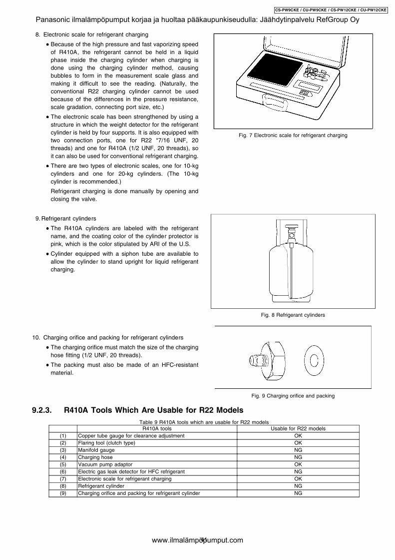
8. Electronic scale for refrigerant charging
• • • • Because of the high pressure and fast vaporizing speedof R410A, the refrigerant cannot be held in a liquidphase inside the charging cylinder when charging isdone using the charging cylinder method, causingbubbles to form in the measurement scale glass andmaking it difficult to see the reading. (Naturally, theconventional R22 charging cylinder cannot be usedbecause of the differences in the pressure resistance,scale gradation, connecting port size, etc.)
• • • • The electronic scale has been strengthened by using astructure in which the weight detector for the refrigerantcylinder is held by four supports. It is also equipped withtwo connection ports, one for R22 *7/16 UNF, 20threads) and one for R410A (1/2 UNF, 20 threads), soit can also be used for conventional refrigerant charging.
• • • • There are two types of electronic scales, one for 10-kgcylinders and one for 20-kg cylinders. (The 10-kgcylinder is recommended.)
Refrigerant charging is done manually by opening andclosing the valve.
9. Refrigerant cylinders
• • • • The R410A cylinders are labeled with the refrigerantname, and the coating color of the cylinder protector ispink, which is the color stipulated by ARI of the U.S.
• • • • Cylinder equipped with a siphon tube are available toallow the cylinder to stand upright for liquid refrigerantcharging.
10. Charging orifice and packing for refrigerant cylinders
• • • • The charging orifice must match the size of the charginghose fitting (1/2 UNF, 20 threads).
• • • • The packing must also be made of an HFC-resistantmaterial.
Fig. 7 Electronic scale for refrigerant charging
Fig. 8 Refrigerant cylinders
Fig. 9 Charging orifice and packing
9.2.3. R410A Tools Which Are Usable for R22 ModelsTable 9 R410A tools which are usable for R22 models
R410A tools Usable for R22 models(1) Copper tube gauge for clearance adjustment OK(2) Flaring tool (clutch type) OK(3) Manifold gauge NG(4) Charging hose NG(5) Vacuum pump adaptor OK(6) Electric gas leak detector for HFC refrigerant NG(7) Electronic scale for refrigerant charging OK(8) Refrigerant cylinder NG(9) Charging orifice and packing for refrigerant cylinder NG
41
CS-PW9CKE / CU-PW9CKE / CS-PW12CKE / CU-PW12CKE
Panasonic ilmalämpöpumput korjaa ja huoltaa pääkaupunkiseudulla: Jäähdytinpalvelu RefGroup Oy
www.ilmalämpöpumput.com
9.3. REFRIGERANT PIPING WORK
When working with refrigerant piping, the following points mustbe carefully observed: no moisture od dust must be allowed toenter the piping, and there must be no refrigerant leaks.
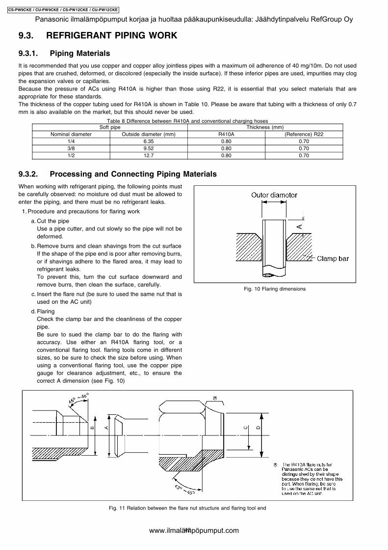
1. Procedure and precautions for flaring work
a. Cut the pipeUse a pipe cutter, and cut slowly so the pipe will not bedeformed.
b. Remove burrs and clean shavings from the cut surfaceIf the shape of the pipe end is poor after removing burrs,or if shavings adhere to the flared area, it may lead torefrigerant leaks.To prevent this, turn the cut surface downward andremove burrs, then clean the surface, carefully.
c. Insert the flare nut (be sure to used the same nut that isused on the AC unit)
d. FlaringCheck the clamp bar and the cleanliness of the copperpipe.Be sure to sued the clamp bar to do the flaring withaccuracy. Use either an R410A flaring tool, or aconventional flaring tool. flaring tools come in differentsizes, so be sure to check the size before using. Whenusing a conventional flaring tool, use the copper pipegauge for clearance adjustment, etc., to ensure thecorrect A dimension (see Fig. 10)
Fig. 10 Flaring dimensions
9.3.1. Piping Materials
It is recommended that you use copper and copper alloy jointless pipes with a maximum oil adherence of 40 mg/10m. Do not usedpipes that are crushed, deformed, or discolored (especially the inside surface). If these inferior pipes are used, impurities may clogthe expansion valves or capillaries.Because the pressure of ACs using R410A is higher than those using R22, it is essential that you select materials that areappropriate for these standards.The thickness of the copper tubing used for R410A is shown in Table 10. Please be aware that tubing with a thickness of only 0.7mm is also available on the market, but this should never be used.
Table 8 Difference between R410A and conventional charging hosesSoft pipe Thickness (mm)
Nominal diameter Outside diameter (mm) R410A (Reference) R221/4 6.35 0.80 0.703/8 9.52 0.80 0.701/2 12.7 0.80 0.70
9.3.2. Processing and Connecting Piping Materials
Fig. 11 Relation between the flare nut structure and flaring tool end
42
CS-PW9CKE / CU-PW9CKE / CS-PW12CKE / CU-PW12CKE
Panasonic ilmalämpöpumput korjaa ja huoltaa pääkaupunkiseudulla: Jäähdytinpalvelu RefGroup Oy
www.ilmalämpöpumput.com
2. Procedure and precautions for flare connection
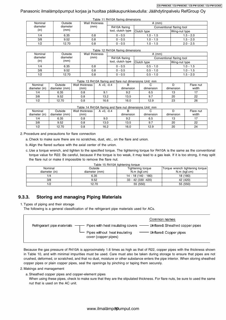
Table 11 R410A flaring dimensionsNominaldiameter
(in)
Outsidediameter
(mm)
Wall thickness(mm)
A (mm)R410A flaring
tool, clutch typeConventional flaring tool
Clutch type Wing-nut type1/4 6.35 0.8 0 - 0.5 1.0 - 1.5 1.5 - 2.03/8 9.52 0.8 0 - 0.5 1.0 - 1.5 1.5 - 2.01/2 12.70 0.8 0 - 0.5 1.0 - 1.5 2.0 - 2.5
Table 12 R410A flaring dimensionsNominaldiameter
(in)
Outsidediameter
(mm)
Wall thickness(mm)
A (mm)R410A flaring
tool, clutch typeConventional flaring tool
Clutch type Wing-nut type1/4 6.35 0.8 0 - 0.5 0.5 - 1.0 1.0 - 1.53/8 9.52 0.8 0 - 0.5 0.5 - 1.0 1.0 - 1.51/2 12.70 0.8 0 - 0.5 0.5 - 1.0 1.5 - 2.0
Table 13 R410A flaring and flare nut dimensions Unit: mmNominal
diameter (in)Outside
diameter (mm)Wall thickness
(mm)A +0, -0.4 B
dimensionC
dimensionD
dimensionFlare nut
width1/4 6.35 0.8 9.1 9.2 6.5 13 173/8 9.52 0.8 13.2 13.5 9.7 20 221/2 12.70 0.8 16.6 16.0 12.9 23 26
Table 14 R410A flaring and flare nut dimensions Unit: mmNominal
diameter (in)Outside
diameter (mm)Wall thickness
(mm)A +0, -0.4 B
dimensionC
dimensionD
dimensionFlare nut
width1/4 6.35 0.8 9.0 9.2 6.5 13 173/8 9.52 0.8 13.0 13.5 9.7 20 221/2 12.70 0.8 16.2 16.0 12.9 20 24
a. Check to make sure there are no scratches, dust, etc., on the flare and union.
b. Align the flared surface with the axial center of the union.
c. Use a torque wrench, and tighten to the specified torque. The tightening torque for R410A is the same as the conventionaltorque value for R22. Be careful, because if the torque is too weak, it may lead to a gas leak. If it is too strong, it may splitthe flare nut or make it impossible to remove the flare nut.
Table 15 R410A tightening torqueNominal
diameter (in)Outside
diameter (mm)Tightening torque
N.m (kgf.cm)Torque wrench tightening torque
N.m (kgf.cm)1/4 6.35 14 - 18 (140 - 180) 18 (180)3/8 9.52 33 - 42 (330 -420) 42 (420)1/2 12.70 55 (550) 55 (550)
9.3.3. Storing and managing Piping Materials
1. Types of piping and their storageThe following is a general classification of the refrigerant pipe materials used for ACs.
Because the gas pressure of R410A is approximately 1.6 times as high as that of R22, copper pipes with the thickness shownin Table 10, and with minimal impurities must be used. Care must also be taken during storage to ensure that pipes are notcrushed, deformed, or scratched, and that no dust, moisture or other substance enters the pipe interior. When storing sheathedcopper pipes or plain copper pipes, seal the openings by pinching or taping them securely.
2. Makings and management
a. Sheathed copper pipes and copper-element pipesWhen using these pipes, check to make sure that they are the stipulated thickness. For flare nuts, be sure to used the samenut that is used on the AC unit.
43
CS-PW9CKE / CU-PW9CKE / CS-PW12CKE / CU-PW12CKE
Panasonic ilmalämpöpumput korjaa ja huoltaa pääkaupunkiseudulla: Jäähdytinpalvelu RefGroup Oy
www.ilmalämpöpumput.com
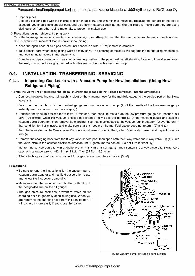
Precautions
• • • • Be sure to read the instructions for the vacuum pump,vacuum pump adaptor and manifold gauge prior to use,and follow the instructions carefully.
• • • • Make sure that the vacuum pump is filled with oil up tothe designated line on the oil gauge.
• • • • The gas pressure back flow prevention valve on thecharging hose is generally open during use. When youare removing the charging hose from the service port, itwill come off more easily if you close this valve.
Fig. 12 Vacuum pump air purging configuration
b. Copper pipesUse only copper pipes with the thickness given in table 10, and with minimal impurities. Because the surface of the pipe isexposed, you should take special care, and also take measures such as marking the pipes to make sure they are easilydistinguished from other piping materials, to prevent mistaken use.
3. Precautions during refrigerant piping workTake the following precautions on-site when connecting pipes. (Keep in mind that the need to control the entry of moisture anddust is even more important that in conventional piping).
a. Keep the open ends of all pipes sealed until connection with AC equipment is complete.
b. Take special care when doing piping work on rainy days. The entering of moisture will degrade the refrigerating machine oil,and lead to malfunctions in the equipment.
c. Complete all pipe connections in as short a time as possible. If the pipe must be left standing for a long time after removingthe seal, it must be thoroughly purged with nitrogen, or dried with a vacuum pump.
9.4. INSTALLATION, TRANSFERRING, SERVICING
9.4.1. Inspecting Gas Leaks with a Vacuum Pump for New Installations (Using NewRefrigerant Piping)
1. From the viewpoint of protecting the global environment, please do not release refrigerant into the atmosphere.
a. Connect the projecting side (pin-pushing side) of the charging hose for the manifold gauge to the service port of the 3-wayvalve. (1)
b. Fully open the handle Lo of the manifold gauge and run the vacuum pump. (2) (If the needle of the low-pressure gaugeinstantly reaches vacuum, re-check step a).)
c. Continue the vacuum process for at least 15 minutes, then check to make sure the low-pressure gauge has reached -0.1MPa (-76 cmHg). Once the vacuum process has finished, fully close the handle Lo of the manifold gauge and stop thevacuum pump operation, then remove the charging hose that is connected to the vacuum pump adaptor. (Leave the unit inthat condition for 1-2 minutes, and make sure that the needle of the manifold gauge does not return.) (2) and (3)
d. Turn the valve stem of the 2-way valve 90 counter-clockwise to open it, then, after 10 seconds, close it and inspect for a gasleak (4)
e. Remove the charging hose from the 3-way valve service port, then open both the 2-way valve and 3-way valve. (1) (4) (Turnthe valve stem in the counter-clockwise direction until it gently makes contact. Do not turn it forcefully).
f. Tighten the service port cap with a torque wrench (18 N.m (1.8 kgf.m)). (5) Then tighten the 2-way valve and 3-way valvecaps with a torque wrench (42 N.m (4.2 kgf.m)) or (55 N.m (5.5 kgf.m)).
g. After attaching each of the caps, inspect for a gas leak around the cap area. (5) (6)
44
CS-PW9CKE / CU-PW9CKE / CS-PW12CKE / CU-PW12CKE
Panasonic ilmalämpöpumput korjaa ja huoltaa pääkaupunkiseudulla: Jäähdytinpalvelu RefGroup Oy
www.ilmalämpöpumput.com
9.4.2. Transferring (Using New Refrigerant Piping)
1. Removing the unit
a. Collecting the refrigerant into the outdoor unit by pumping downThe refrigerant can be collected into the outdoor unit (pumping down) by pressing the TEST RUN button, even when thetemperature of the room is low.
• • • • Check to make sure that the valve stems of the 2-way valve and 3-way valve have been opened by turning them counter-clockwise. (Remove the valve stem caps and check to see that the valve stems are fully opened position. Always usea hex wrench (with 4-mm opposing sides) to operate the valve stems.)
• • • • Press the TEST RUN button on the indoor unit, and allow preliminary for 5-6 minutes. (TEST RUN mode)
• • • • After stopping the operation, let the unit sit for about 3 minutes, then close the 2-way valve by turning the valve stem inthe clockwise direction.
• • • • Press the TEST RUN button on the indoor unit again, and after 2-3 minutes of operation, turn the valve stem of the 3-way valve quickly in the clockwise direction to close it, then stop the operation.
• • • • Tighten the caps of the 2-way valve and 3-way valve to the stipulated torque.
• • • • Remove the connection pipes (liquid side and gas side).
2. Installing the unitInstall the unit using new refrigerant piping. Follow the instructions in section 4.1 to evacuate the pipes connecting the indoorand outdoor units, and the pipes of the indoor unit, and check for gas leaks.
9.4.3. AC Units Replacement (Using Existing Refrigerant Piping)
When replacing and R410A AC unit with another R410A AC unit, you should re-flare the refrigerant piping. Even though thereplacement AC unit uses the R410A, problems occur when, for example, either the AC unit maker or the refrigerating machine oilis different.When replacing an R22 AC unit with an R410A AC unit, the following checks and cleaning procedures are necessary but aredifficult to do because of the chemical characteristics of the refrigerating machine oil (as described in items c) and d) of section10.1.1.(2)). In this case, you should use new refrigerant piping rather than the existing piping.
1. Piping checkBecause of the different pressure characteristics of R22 and R410A, the design pressure for the equipment is 1.6 timesdifferent. the wall thickness of the piping must comply with that shown in Table 10, but this is not easy to check. Also, even ifthe thickness is correct, there may be flattened or bent portions midway through the piping due to sharp curves. Buried sectionsof the piping also cannot be checked.
2. Pipe cleaningA large quantity of refrigerating machine oil (mineral oil) adheres to existing pipes due to the refrigeration cycle circulation. If thepipes are used just as they are for the R410A cycle, the capacity will be lowered due to the incompatibility of this oil with theR410A, or irregularities may occur in the refrigeration cycle. For this reason, the piping must be thoroughly cleaned, but this isdifficult with the present technology.
9.4.4. Refrigerant Compatibility (Using R410A Refrigerant in R22 ACs and Vice Versa)
Do not operate an existing R22 AC with the new R410A refrigerant. Doing so would result in improper functioning of the equipmentor malfunction, and might lead to a major accident such as an explosion in the refrigeration cycle. Similarly, do not operate anR410A AC with R22 refrigerant. The chemical reaction between the refrigerating machine oil used in R410A ACs and the chlorinethat is contained in R22 would cause the refrigerating machine oil to degrade and lead to malfunction.
9.4.5. Recharging Refrigerant During Servicing
When recharging is necessary, insert the specified amount of new refrigerant in accordance with the following procedure.
1. Connect the charging hose to the service port of the outdoor unit.
2. Connect the charging hose to the vacuum pump adaptor. At this time, fully open the 2-way valve and 3-way valve.
3. Fully open the handle Lo of the manifold gauge, turn on the power of the vacuum pump and continue the vacuum process forat least one hour.
4. Confirm that the low pressure gauge shows a reading of -0.1 Mpa (-76 cmHg), then fully close the handle Lo, and turn off thevacuum pump. Wait for 1-2 minutes, then check to make sure that the needle of the Low pressure gauge has not returned. SeeFig. 13 for the remaining steps of this procedure.
45
CS-PW9CKE / CU-PW9CKE / CS-PW12CKE / CU-PW12CKE
Panasonic ilmalämpöpumput korjaa ja huoltaa pääkaupunkiseudulla: Jäähdytinpalvelu RefGroup Oy
www.ilmalämpöpumput.com
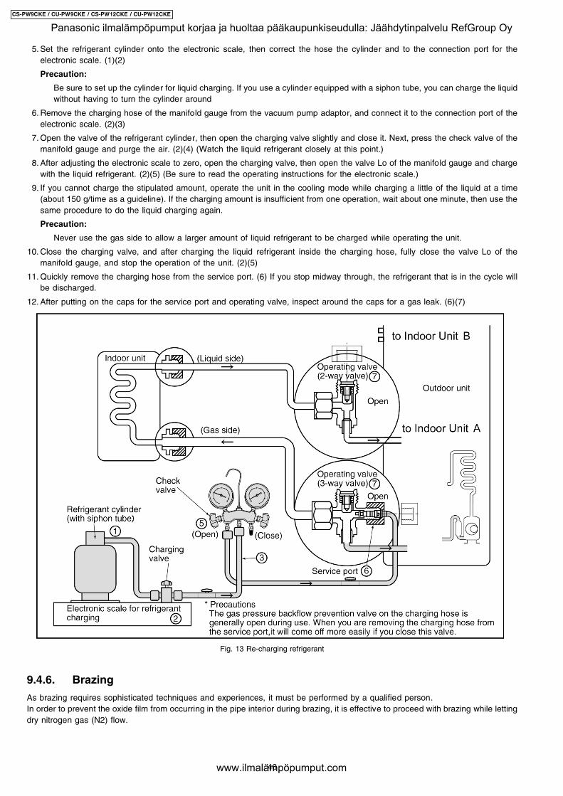
5. Set the refrigerant cylinder onto the electronic scale, then correct the hose the cylinder and to the connection port for theelectronic scale. (1)(2)
Precaution:
Be sure to set up the cylinder for liquid charging. If you use a cylinder equipped with a siphon tube, you can charge the liquidwithout having to turn the cylinder around
6. Remove the charging hose of the manifold gauge from the vacuum pump adaptor, and connect it to the connection port of theelectronic scale. (2)(3)
7. Open the valve of the refrigerant cylinder, then open the charging valve slightly and close it. Next, press the check valve of themanifold gauge and purge the air. (2)(4) (Watch the liquid refrigerant closely at this point.)
8. After adjusting the electronic scale to zero, open the charging valve, then open the valve Lo of the manifold gauge and chargewith the liquid refrigerant. (2)(5) (Be sure to read the operating instructions for the electronic scale.)
9. If you cannot charge the stipulated amount, operate the unit in the cooling mode while charging a little of the liquid at a time(about 150 g/time as a guideline). If the charging amount is insufficient from one operation, wait about one minute, then use thesame procedure to do the liquid charging again.
Precaution:
Never use the gas side to allow a larger amount of liquid refrigerant to be charged while operating the unit.
10. Close the charging valve, and after charging the liquid refrigerant inside the charging hose, fully close the valve Lo of themanifold gauge, and stop the operation of the unit. (2)(5)
11. Quickly remove the charging hose from the service port. (6) If you stop midway through, the refrigerant that is in the cycle willbe discharged.
12. After putting on the caps for the service port and operating valve, inspect around the caps for a gas leak. (6)(7)
Fig. 13 Re-charging refrigerant
9.4.6. Brazing
As brazing requires sophisticated techniques and experiences, it must be performed by a qualified person.In order to prevent the oxide film from occurring in the pipe interior during brazing, it is effective to proceed with brazing while lettingdry nitrogen gas (N2) flow.
46
CS-PW9CKE / CU-PW9CKE / CS-PW12CKE / CU-PW12CKE
Panasonic ilmalämpöpumput korjaa ja huoltaa pääkaupunkiseudulla: Jäähdytinpalvelu RefGroup Oy
www.ilmalämpöpumput.com
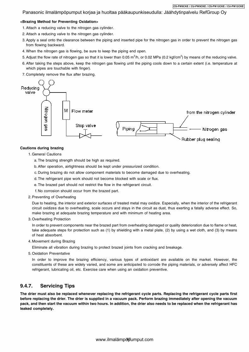
<Brazing Method for Preventing Oxidation>
1. Attach a reducing valve to the nitrogen gas cylinder.
2. Attach a reducing valve to the nitrogen gas cylinder.
3. Apply a seal onto the clearance between the piping and inserted pipe for the nitrogen gas in order to prevent the nitrogen gasfrom flowing backward.
4. When the nitrogen gas is flowing, be sure to keep the piping end open.
5. Adjust the flow rate of nitrogen gas so that it is lower than 0.05 m3/h, or 0.02 MPa (0.2 kgf/cm2) by means of the reducing valve.
6. After taking the steps above, keep the nitrogen gas flowing until the piping cools down to a certain extent (i.e. temperature atwhich pipes are touchable with finger).
7. Completely remove the flux after brazing.
Cautions during brazing
1. General Cautions
a. The brazing strength should be high as required.
b. After operation, airtightness should be kept under pressurized condition.
c. During brazing do not allow component materials to become damaged due to overheating.
d. The refrigerant pipe work should not become blocked with scale or flux.
e. The brazed part should not restrict the flow in the refrigerant circuit.
f. No corrosion should occur from the brazed part.
2. Preventing of Overheating
Due to heating, the interior and exterior surfaces of treated metal may oxidize. Especially, when the interior of the refrigerantcircuit oxidizes due to overheating, scale occurs and stays in the circuit as dust, thus exerting a fatally adverse effect. So,make brazing at adequate brazing temperature and with minimum of heating area.
3. Overheating Protection
In order to prevent components near the brazed part from overheating damaged or quality deterioration due to flame or heat,take adequate steps for protection such as (1) by shielding with a metal plate, (2) by using a wet cloth, and (3) by meansof heat absorbent.
4. Movement during Brazing
Eliminate all vibration during brazing to protect brazed joints from cracking and breakage.
5. Oxidation Preventative
In order to improve the brazing efficiency, various types of antioxidant are available on the market. However, theconstituents of these are widely varied, and some are anticipated to corrode the piping materials, or adversely affect HFCrefrigerant, lubricating oil, etc. Exercise care when using an oxidation preventive.
9.4.7. Servicing Tips
The drier must also be replaced whenever replacing the refrigerant cycle parts. Replacing the refrigerant cycle parts firstbefore replacing the drier. The drier is supplied in a vacuum pack. Perform brazing immediately after opening the vacuumpack, and then start the vacuum within two hours. In addition, the drier also needs to be replaced when the refrigerant hasleaked completely.
47
CS-PW9CKE / CU-PW9CKE / CS-PW12CKE / CU-PW12CKE
Panasonic ilmalämpöpumput korjaa ja huoltaa pääkaupunkiseudulla: Jäähdytinpalvelu RefGroup Oy
www.ilmalämpöpumput.com
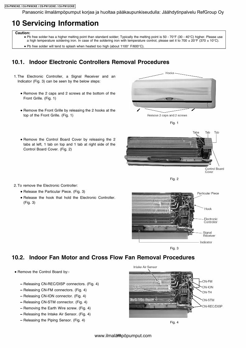
1. The Electronic Controller, a Signal Receiver and anIndicator (Fig. 3) can be seen by the below steps:
• • • • Remove the 2 caps and 2 screws at the bottom of theFront Grille. (Fig. 1)
• • • • Remove the Front Grille by releasing the 2 hooks at thetop of the Front Grille. (Fig. 1)
• • • • Remove the Control Board Cover by releasing the 2tabs at left, 1 tab on top and 1 tab at right side of theControl Board Cover. (Fig. 2)
2. To remove the Electronic Controller:
• • • • Release the Particular Piece. (Fig. 3)
• • • • Release the hook that hold the Electronic Controller.(Fig. 3)
• • • • Remove the Control Board by:-
− − − − Releasing CN-REC/DISP connectors. (Fig. 4)
− − − − Releasing CN-FM connectors. (Fig. 4)
− − − − Releasing CN-ION connector. (Fig. 4)
− − − − Releasing CN-STM connector. (Fig. 4)
− − − − Removing the Earth Wire screw. (Fig. 4)
− − − − Releasing the Intake Air Sensor. (Fig. 4)
− − − − Releasing the Piping Sensor. (Fig. 4)
Fig. 1
Fig. 2
Fig. 3
Fig. 4
10 Servicing InformationCaution:
• • • • Pb free solder has a higher melting point than standard solder; Typically the melting point is 50 - 70°F (30 - 40°C) higher. Please usea high temperature soldering iron. In case of the soldering iron with temperature control, please set it to 700 ± 20°F (370 ± 10°C).
• • • • Pb free solder will tend to splash when heated too high (about 1100° F/600°C).
10.1. Indoor Electronic Controllers Removal Procedures
10.2. Indoor Fan Motor and Cross Flow Fan Removal Procedures
48
CS-PW9CKE / CU-PW9CKE / CS-PW12CKE / CU-PW12CKE
Panasonic ilmalämpöpumput korjaa ja huoltaa pääkaupunkiseudulla: Jäähdytinpalvelu RefGroup Oy
www.ilmalämpöpumput.com
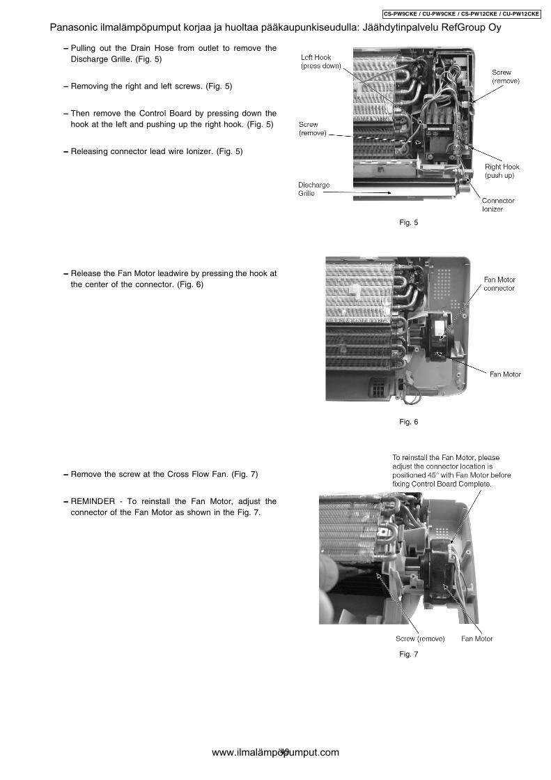
− − − − Pulling out the Drain Hose from outlet to remove theDischarge Grille. (Fig. 5)
− − − − Removing the right and left screws. (Fig. 5)
− − − − Then remove the Control Board by pressing down thehook at the left and pushing up the right hook. (Fig. 5)
− − − − Releasing connector lead wire Ionizer. (Fig. 5)
− − − − Release the Fan Motor leadwire by pressing the hook atthe center of the connector. (Fig. 6)
− − − − Remove the screw at the Cross Flow Fan. (Fig. 7)
− − − − REMINDER - To reinstall the Fan Motor, adjust theconnector of the Fan Motor as shown in the Fig. 7.
Fig. 5
Fig. 6
Fig. 7
49
CS-PW9CKE / CU-PW9CKE / CS-PW12CKE / CU-PW12CKE
Panasonic ilmalämpöpumput korjaa ja huoltaa pääkaupunkiseudulla: Jäähdytinpalvelu RefGroup Oy
www.ilmalämpöpumput.com
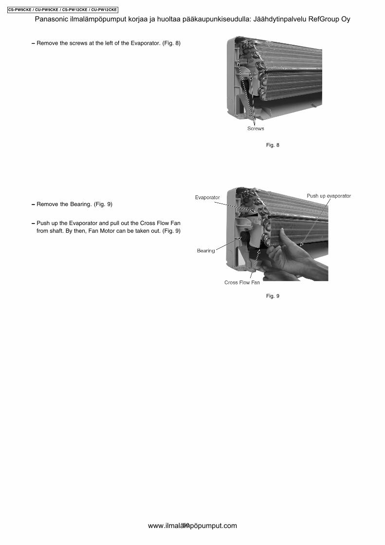
− − − − Remove the screws at the left of the Evaporator. (Fig. 8)
− − − − Remove the Bearing. (Fig. 9)
− − − − Push up the Evaporator and pull out the Cross Flow Fanfrom shaft. By then, Fan Motor can be taken out. (Fig. 9)
Fig. 8
Fig. 9
50
CS-PW9CKE / CU-PW9CKE / CS-PW12CKE / CU-PW12CKE
Panasonic ilmalämpöpumput korjaa ja huoltaa pääkaupunkiseudulla: Jäähdytinpalvelu RefGroup Oy
www.ilmalämpöpumput.com
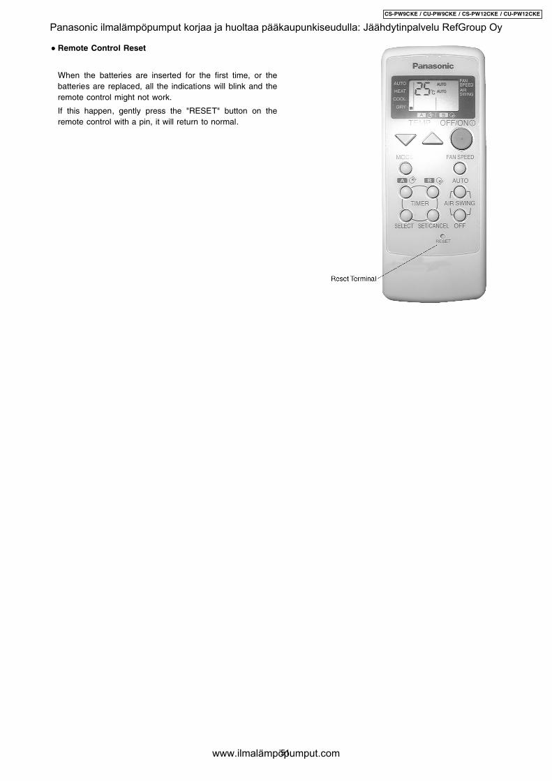
• • • • Remote Control Reset
When the batteries are inserted for the first time, or thebatteries are replaced, all the indications will blink and theremote control might not work.
If this happen, gently press the "RESET" button on theremote control with a pin, it will return to normal.
51
CS-PW9CKE / CU-PW9CKE / CS-PW12CKE / CU-PW12CKE
Panasonic ilmalämpöpumput korjaa ja huoltaa pääkaupunkiseudulla: Jäähdytinpalvelu RefGroup Oy
www.ilmalämpöpumput.com
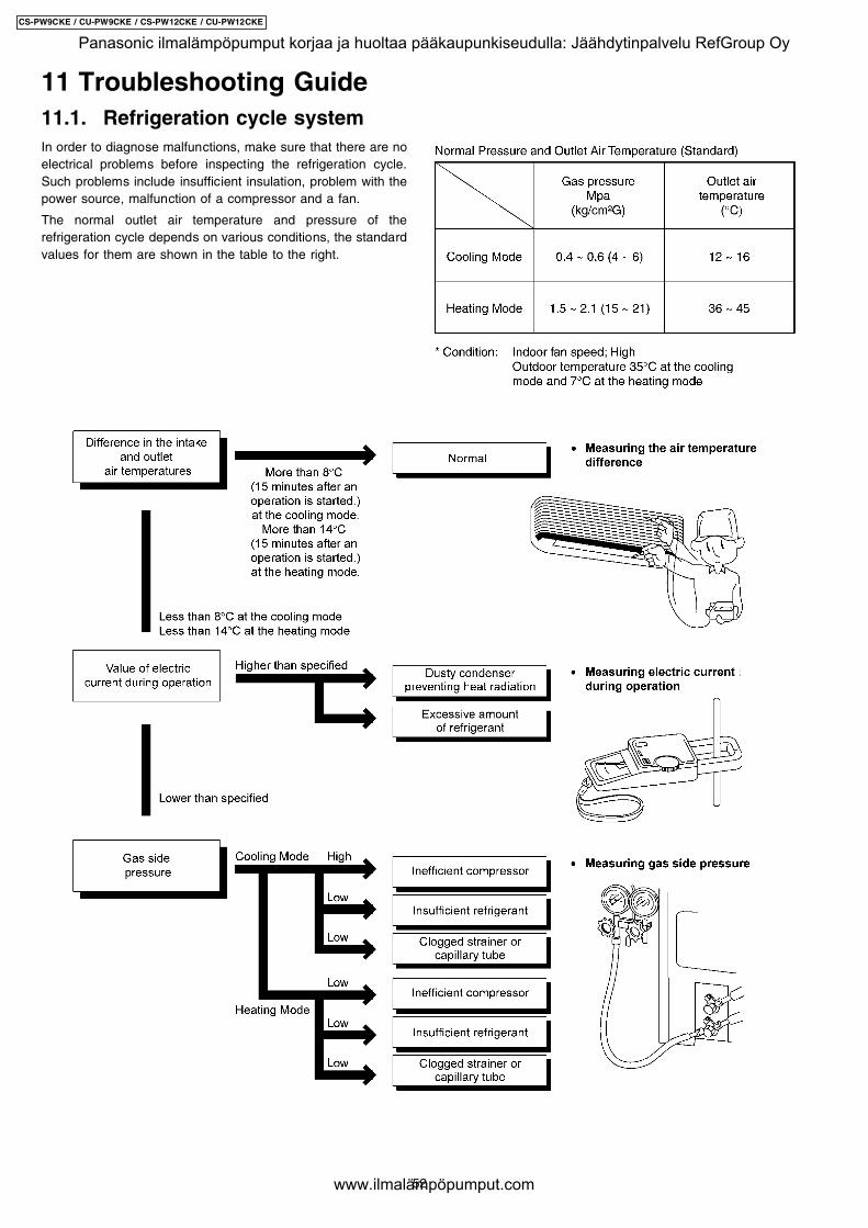
In order to diagnose malfunctions, make sure that there are noelectrical problems before inspecting the refrigeration cycle.Such problems include insufficient insulation, problem with thepower source, malfunction of a compressor and a fan.
The normal outlet air temperature and pressure of therefrigeration cycle depends on various conditions, the standardvalues for them are shown in the table to the right.
11 Troubleshooting Guide11.1. Refrigeration cycle system
52
CS-PW9CKE / CU-PW9CKE / CS-PW12CKE / CU-PW12CKE
Panasonic ilmalämpöpumput korjaa ja huoltaa pääkaupunkiseudulla: Jäähdytinpalvelu RefGroup Oy
www.ilmalämpöpumput.com
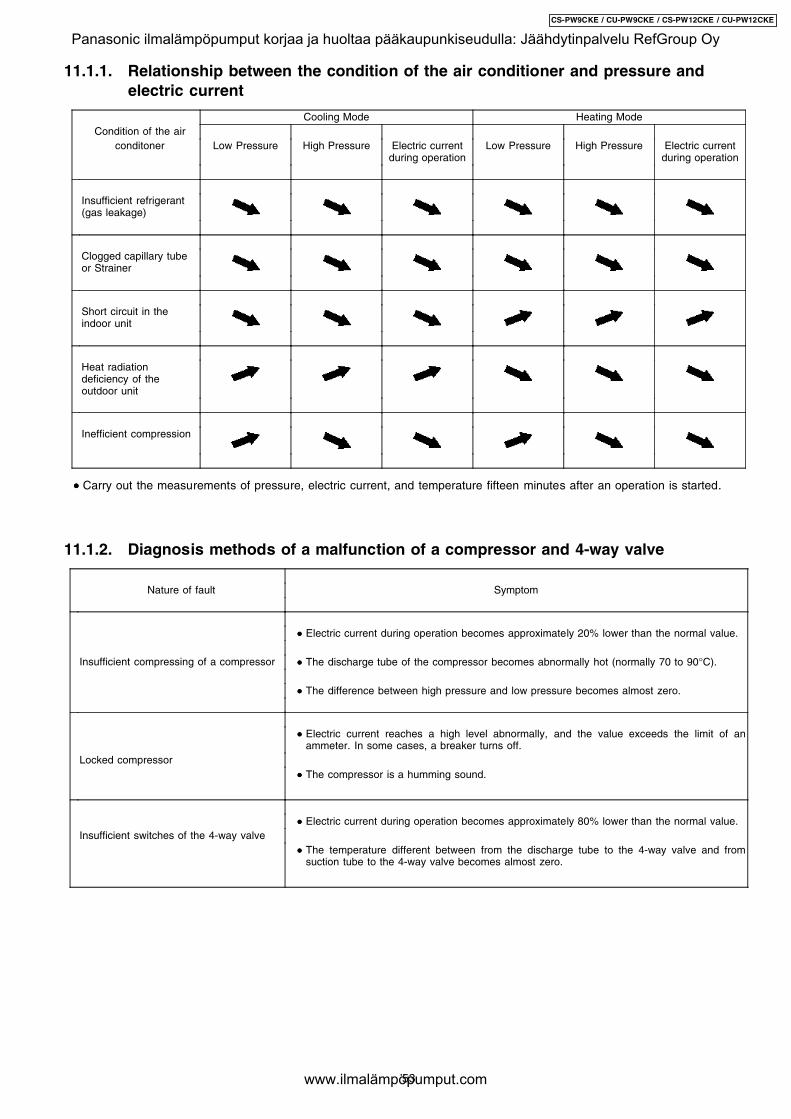
11.1.1. Relationship between the condition of the air conditioner and pressure andelectric current
Cooling Mode Heating ModeCondition of the air
conditoner Low Pressure High Pressure Electric currentduring operation
Low Pressure High Pressure Electric currentduring operation
Insufficient refrigerant(gas leakage)
Clogged capillary tubeor Strainer
Short circuit in theindoor unit
Heat radiationdeficiency of theoutdoor unit
Inefficient compression
• • • • Carry out the measurements of pressure, electric current, and temperature fifteen minutes after an operation is started.
11.1.2. Diagnosis methods of a malfunction of a compressor and 4-way valve
Nature of fault Symptom
• • • • Electric current during operation becomes approximately 20% lower than the normal value.
Insufficient compressing of a compressor • • • • The discharge tube of the compressor becomes abnormally hot (normally 70 to 90°C).
• • • • The difference between high pressure and low pressure becomes almost zero.
• • • • Electric current reaches a high level abnormally, and the value exceeds the limit of anammeter. In some cases, a breaker turns off.
Locked compressor • • • • The compressor is a humming sound.
• • • • Electric current during operation becomes approximately 80% lower than the normal value.Insufficient switches of the 4-way valve
• • • • The temperature different between from the discharge tube to the 4-way valve and fromsuction tube to the 4-way valve becomes almost zero.
53
CS-PW9CKE / CU-PW9CKE / CS-PW12CKE / CU-PW12CKE
Panasonic ilmalämpöpumput korjaa ja huoltaa pääkaupunkiseudulla: Jäähdytinpalvelu RefGroup Oy
www.ilmalämpöpumput.com
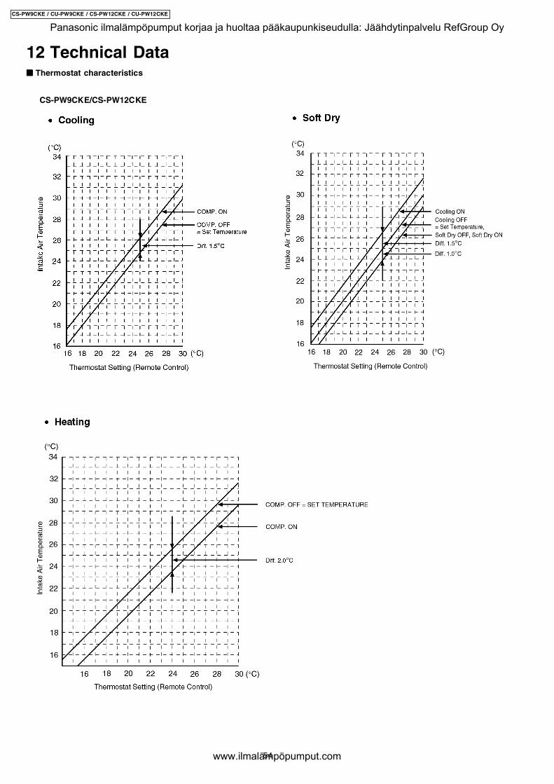
12 Technical Data"""" Thermostat characteristics
CS-PW9CKE/CS-PW12CKE
54
CS-PW9CKE / CU-PW9CKE / CS-PW12CKE / CU-PW12CKE
Panasonic ilmalämpöpumput korjaa ja huoltaa pääkaupunkiseudulla: Jäähdytinpalvelu RefGroup Oy
www.ilmalämpöpumput.com
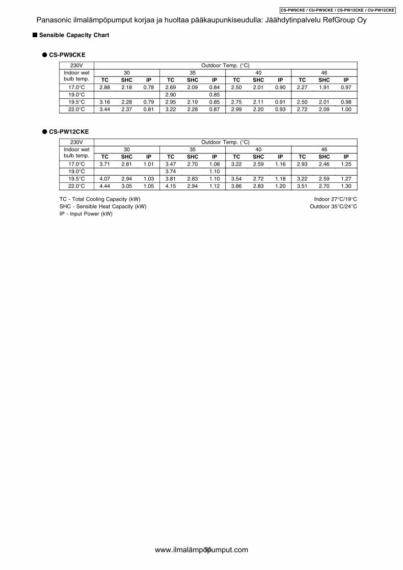
"""" Sensible Capacity Chart
#### CS-PW9CKE
230V Outdoor Temp. (°C)Indoor wetbulb temp.
30 35 40 46TC SHC IP TC SHC IP TC SHC IP TC SHC IP
17.0°C 2.88 2.18 0.78 2.69 2.09 0.84 2.50 2.01 0.90 2.27 1.91 0.9719.0°C 2.90 0.8519.5°C 3.16 2.28 0.79 2.95 2.19 0.85 2.75 2.11 0.91 2.50 2.01 0.9822.0°C 3.44 2.37 0.81 3.22 2.28 0.87 2.99 2.20 0.93 2.72 2.09 1.00
#### CS-PW12CKE
230V Outdoor Temp. (°C)Indoor wetbulb temp.
30 35 40 46TC SHC IP TC SHC IP TC SHC IP TC SHC IP
17.0°C 3.71 2.81 1.01 3.47 2.70 1.08 3.22 2.59 1.16 2.93 2.46 1.2519.0°C 3.74 1.1019.5°C 4.07 2.94 1.03 3.81 2.83 1.10 3.54 2.72 1.18 3.22 2.59 1.2722.0°C 4.44 3.05 1.05 4.15 2.94 1.12 3.86 2.83 1.20 3.51 2.70 1.30
TC - Total Cooling Capacity (kW) Indoor 27°C/19°CSHC - Sensible Heat Capacity (kW) Outdoor 35°C/24°CIP - Input Power (kW)
55
CS-PW9CKE / CU-PW9CKE / CS-PW12CKE / CU-PW12CKE
Panasonic ilmalämpöpumput korjaa ja huoltaa pääkaupunkiseudulla: Jäähdytinpalvelu RefGroup Oy
www.ilmalämpöpumput.com
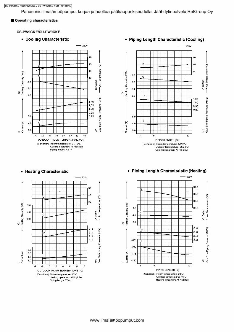
"""" Operating characteristics
CS-PW9CKE/CU-PW9CKE
56
CS-PW9CKE / CU-PW9CKE / CS-PW12CKE / CU-PW12CKE
Panasonic ilmalämpöpumput korjaa ja huoltaa pääkaupunkiseudulla: Jäähdytinpalvelu RefGroup Oy
www.ilmalämpöpumput.com
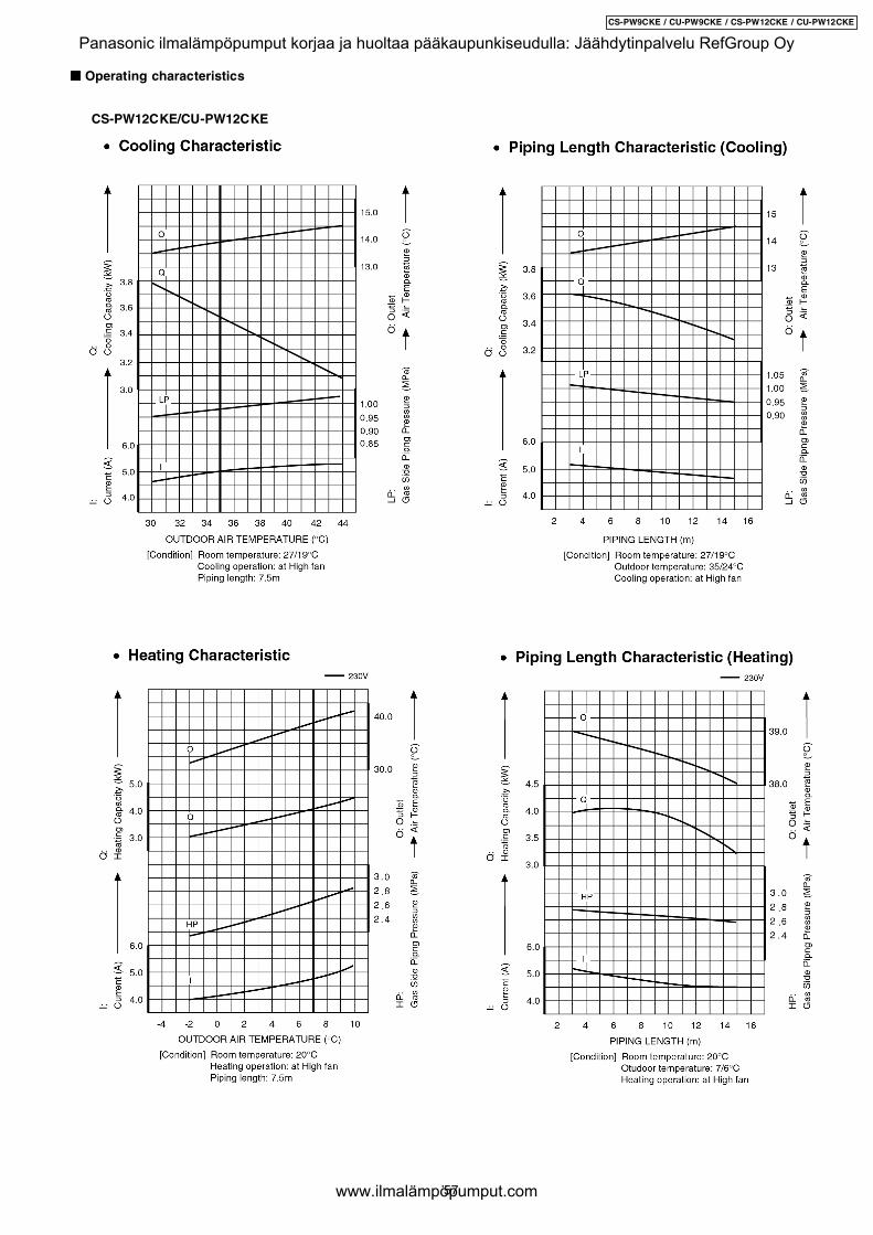
"""" Operating characteristics
CS-PW12CKE/CU-PW12CKE
57
CS-PW9CKE / CU-PW9CKE / CS-PW12CKE / CU-PW12CKE
Panasonic ilmalämpöpumput korjaa ja huoltaa pääkaupunkiseudulla: Jäähdytinpalvelu RefGroup Oy
www.ilmalämpöpumput.com
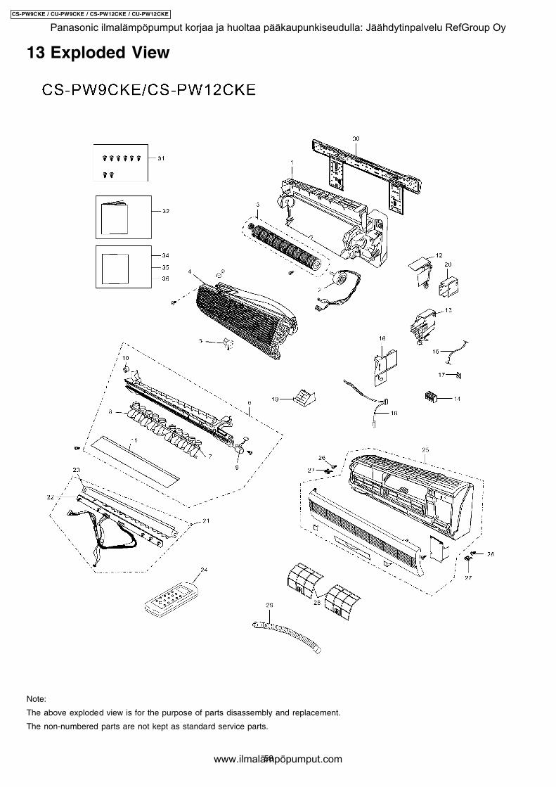
13 Exploded View
Note:
The above exploded view is for the purpose of parts disassembly and replacement.
The non-numbered parts are not kept as standard service parts.
58
CS-PW9CKE / CU-PW9CKE / CS-PW12CKE / CU-PW12CKE
Panasonic ilmalämpöpumput korjaa ja huoltaa pääkaupunkiseudulla: Jäähdytinpalvelu RefGroup Oy
www.ilmalämpöpumput.com
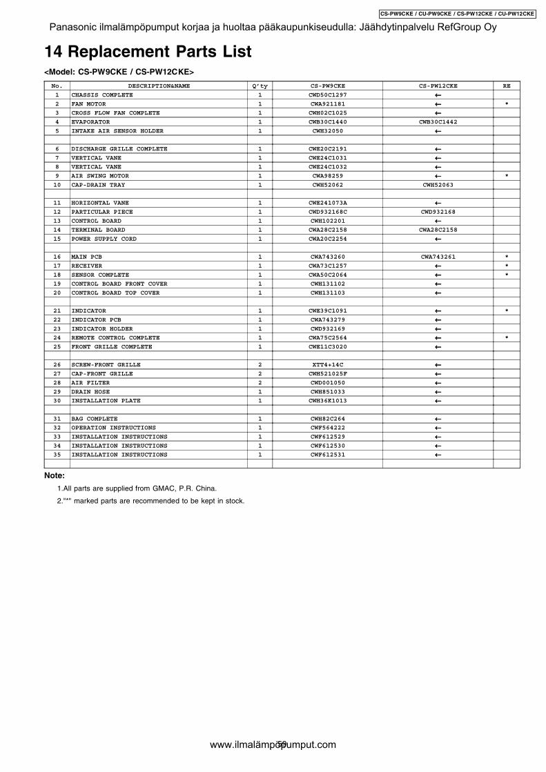
14 Replacement Parts List<Model: CS-PW9CKE / CS-PW12CKE>
No. DESCRIPTION&NAME Q’ty CS-PW9CKE CS-PW12CKE RE
1 CHASSIS COMPLETE 1 CWD50C1297 ←←←←2 FAN MOTOR 1 CWA921181 ←←←← *
3 CROSS FLOW FAN COMPLETE 1 CWH02C1025 ←←←←4 EVAPORATOR 1 CWB30C1440 CWB30C1442
5 INTAKE AIR SENSOR HOLDER 1 CWH32050 ←←←←
6 DISCHARGE GRILLE COMPLETE 1 CWE20C2191 ←←←←7 VERTICAL VANE 1 CWE24C1031 ←←←←8 VERTICAL VANE 1 CWE24C1032 ←←←←9 AIR SWING MOTOR 1 CWA98259 ←←←← *
10 CAP-DRAIN TRAY 1 CWH52062 CWH52063
11 HORIZONTAL VANE 1 CWE241073A ←←←←12 PARTICULAR PIECE 1 CWD932168C CWD932168
13 CONTROL BOARD 1 CWH102201 ←←←←14 TERMINAL BOARD 1 CWA28C2158 CWA28C2158
15 POWER SUPPLY CORD 1 CWA20C2254 ←←←←
16 MAIN PCB 1 CWA743260 CWA743261 *
17 RECEIVER 1 CWA73C1257 ←←←← *
18 SENSOR COMPLETE 1 CWA50C2064 ←←←← *
19 CONTROL BOARD FRONT COVER 1 CWH131102 ←←←←20 CONTROL BOARD TOP COVER 1 CWH131103 ←←←←
21 INDICATOR 1 CWE39C1091 ←←←← *
22 INDICATOR PCB 1 CWA743279 ←←←←23 INDICATOR HOLDER 1 CWD932169 ←←←←24 REMOTE CONTROL COMPLETE 1 CWA75C2564 ←←←← *
25 FRONT GRILLE COMPLETE 1 CWE11C3020 ←←←←
26 SCREW-FRONT GRILLE 2 XTT4+14C ←←←←27 CAP-FRONT GRILLE 2 CWH521025F ←←←←28 AIR FILTER 2 CWD001050 ←←←←29 DRAIN HOSE 1 CWH851033 ←←←←30 INSTALLATION PLATE 1 CWH36K1013 ←←←←
31 BAG COMPLETE 1 CWH82C264 ←←←←32 OPERATION INSTRUCTIONS 1 CWF564222 ←←←←33 INSTALLATION INSTRUCTIONS 1 CWF612529 ←←←←34 INSTALLATION INSTRUCTIONS 1 CWF612530 ←←←←35 INSTALLATION INSTRUCTIONS 1 CWF612531 ←←←←
Note:
1.All parts are supplied from GMAC, P.R. China.
2."*" marked parts are recommended to be kept in stock.
59
CS-PW9CKE / CU-PW9CKE / CS-PW12CKE / CU-PW12CKE
Panasonic ilmalämpöpumput korjaa ja huoltaa pääkaupunkiseudulla: Jäähdytinpalvelu RefGroup Oy
www.ilmalämpöpumput.com
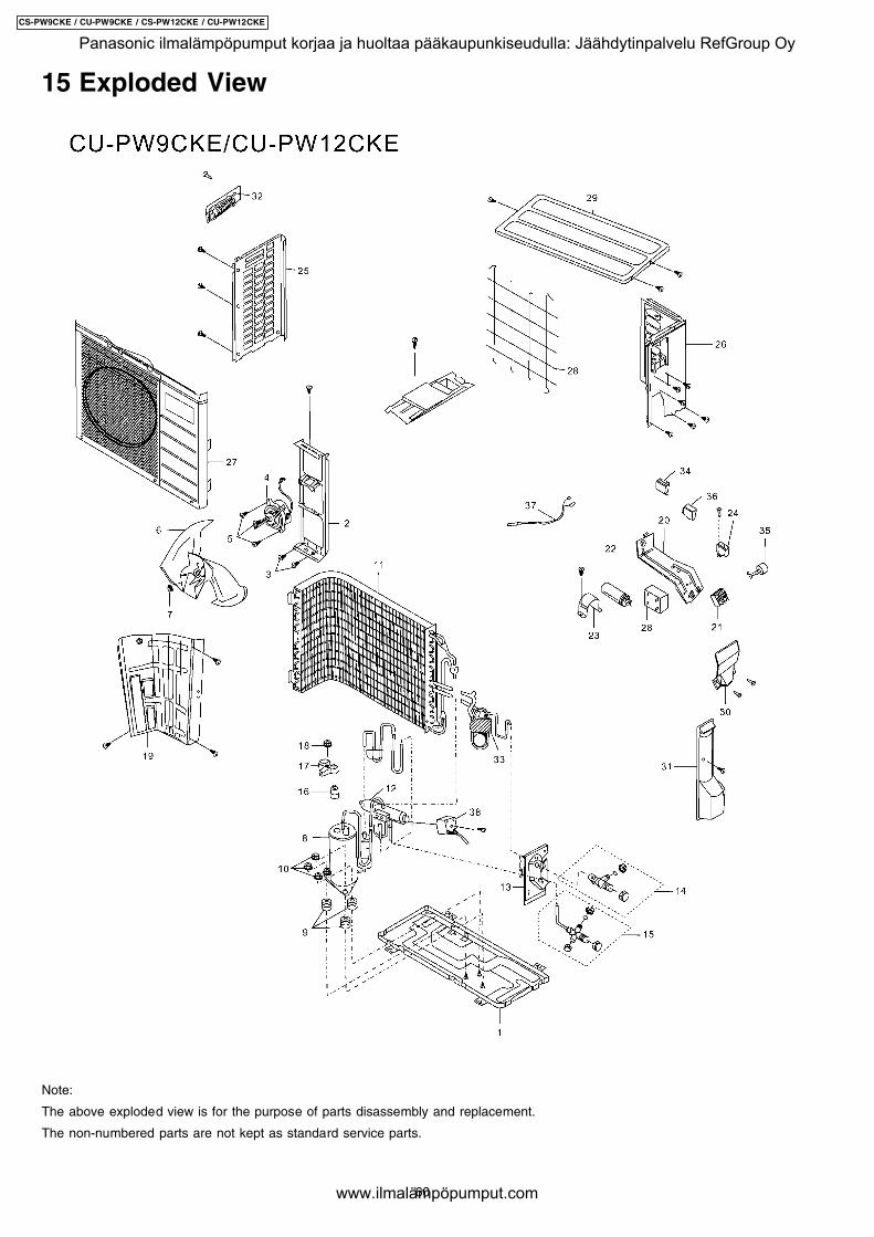
15 Exploded View
Note:
The above exploded view is for the purpose of parts disassembly and replacement.
The non-numbered parts are not kept as standard service parts.
60
CS-PW9CKE / CU-PW9CKE / CS-PW12CKE / CU-PW12CKE
Panasonic ilmalämpöpumput korjaa ja huoltaa pääkaupunkiseudulla: Jäähdytinpalvelu RefGroup Oy
www.ilmalämpöpumput.com
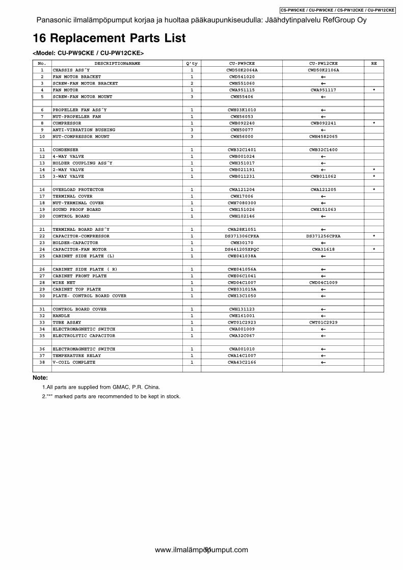
16 Replacement Parts List<Model: CU-PW9CKE / CU-PW12CKE>
No. DESCRIPTION&NAME Q’ty CU-PW9CKE CU-PW12CKE RE
1 CHASSIS ASS´Y 1 CWD50K2064A CWD50K2106A
2 FAN MOTOR BRACKET 1 CWD541020 ←←←←3 SCREW-FAN MOTOR BRACKET 2 CWH551060 ←←←←4 FAN MOTOR 1 CWA951115 CWA951117 *
5 SCREW-FAN MOTOR MOUNT 3 CWH55406 ←←←←
6 PROPELLER FAN ASS´Y 1 CWH03K1010 ←←←←7 NUT-PROPELLER FAN 1 CWH56053 ←←←←8 COMPRESSOR 1 CWB092240 CWB092241 *
9 ANTI-VIBRATION BUSHING 3 CWH50077 ←←←←10 NUT-COMPRESSOR MOUNT 3 CWH56000 CWH4582065
11 CONDENSER 1 CWB32C1401 CWB32C1400
12 4-WAY VALVE 1 CWB001024 ←←←←13 HOLDER COUPLING ASS´Y 1 CWH351017 ←←←←14 2-WAY VALVE 1 CWB021191 ←←←← *
15 3-WAY VALVE 1 CWB011231 CWB011062 *
16 OVERLOAD PROTECTOR 1 CWA121204 CWA121205 *
17 TERMINAL COVER 1 CWH17006 ←←←←18 NUT-TERMINAL COVER 1 CWH7080300 ←←←←19 SOUND PROOF BOARD 1 CWH151026 CWH151063
20 CONTROL BOARD 1 CWH102146 ←←←←
21 TERMINAL BOARD ASS´Y 1 CWA28K1051 ←←←←22 CAPACITOR-COMPRESSOR 1 DS371306CPXA DS371256CPXA *
23 HOLDER-CAPACITOR 1 CWH30170 ←←←←24 CAPACITOR-FAN MOTOR 1 DS441205XPQC CWA31618 *
25 CABINET SIDE PLATE (L) 1 CWE041038A ←←←←
26 CABINET SIDE PLATE ( R) 1 CWE041056A ←←←←27 CABINET FRONT PLATE 1 CWE06C1041 ←←←←28 WIRE NET 1 CWD04C1007 CWD04C1009
29 CABINET TOP PLATE 1 CWE031015A ←←←←30 PLATE- CONTROL BOARD COVER 1 CWH13C1050 ←←←←
31 CONTROL BOARD COVER 1 CWH131123 ←←←←32 HANDLE 1 CWE161001 ←←←←33 TUBE ASSÆY 1 CWT01C2923 CWT01C2929
34 ELECTROMAGNETIC SWITCH 1 CWA001009 ←←←←35 ELECTROLYTIC CAPACITOR 1 CWA32C067 ←←←←
36 ELECTROMAGNETIC SWITCH 1 CWA001010 ←←←←37 TEMPERATURE RELAY 1 CWA14C1007 ←←←←38 V-COIL COMPLETE 1 CWA43C2166 ←←←←
Note:
1.All parts are supplied from GMAC, P.R. China.
2."*" marked parts are recommended to be kept in stock.
61
CS-PW9CKE / CU-PW9CKE / CS-PW12CKE / CU-PW12CKE
Panasonic ilmalämpöpumput korjaa ja huoltaa pääkaupunkiseudulla: Jäähdytinpalvelu RefGroup Oy
www.ilmalämpöpumput.com
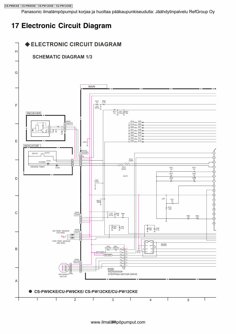
17 Electronic Circuit Diagram
A
B
C
D
E
F
G
H
1 2 3 4 5
SCHEMATIC DIAGRAM 1/3
CS-PW9CKE/CU-PW9CKE/ CS-PW12CKE/CU-PW12CKE
62
CS-PW9CKE / CU-PW9CKE / CS-PW12CKE / CU-PW12CKE
Panasonic ilmalämpöpumput korjaa ja huoltaa pääkaupunkiseudulla: Jäähdytinpalvelu RefGroup Oy
www.ilmalämpöpumput.com
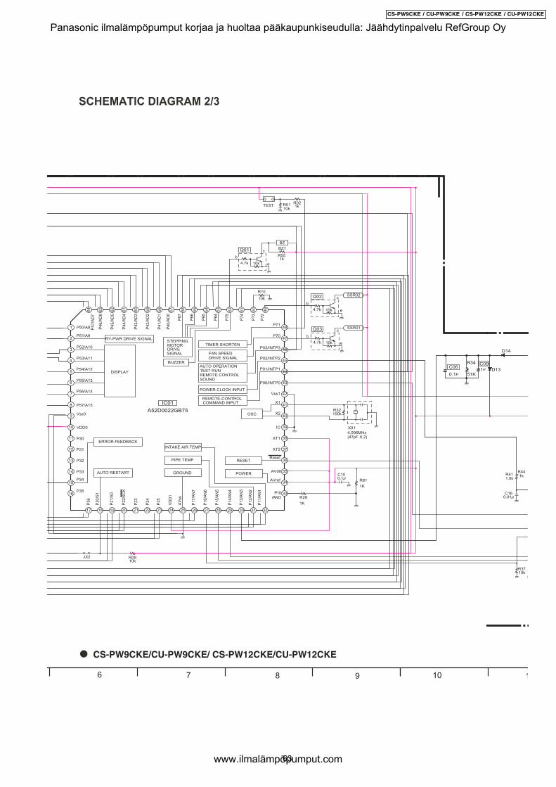
6 7 8 9 10 1
SCHEMATIC DIAGRAM 2/3
CS-PW9CKE/CU-PW9CKE/ CS-PW12CKE/CU-PW12CKE
63
CS-PW9CKE / CU-PW9CKE / CS-PW12CKE / CU-PW12CKE
Panasonic ilmalämpöpumput korjaa ja huoltaa pääkaupunkiseudulla: Jäähdytinpalvelu RefGroup Oy
www.ilmalämpöpumput.com
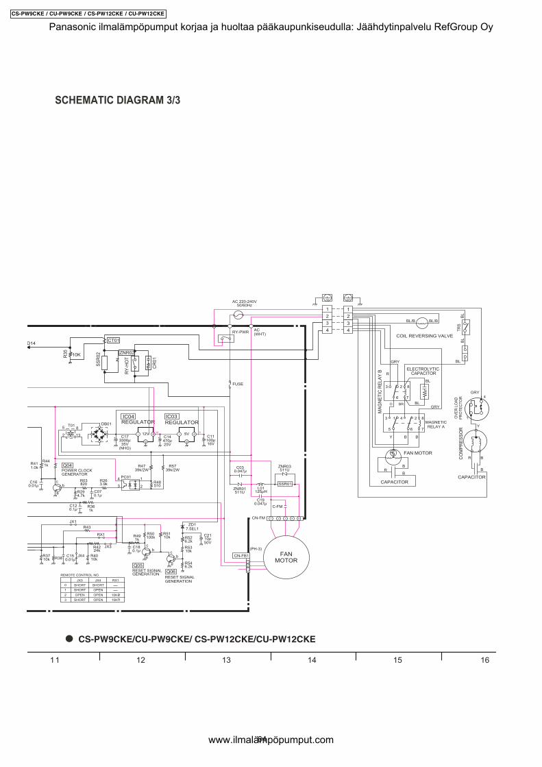
11 12 13 14 15 16
SCHEMATIC DIAGRAM 3/3
CS-PW9CKE/CU-PW9CKE/ CS-PW12CKE/CU-PW12CKE
64
CS-PW9CKE / CU-PW9CKE / CS-PW12CKE / CU-PW12CKE
Panasonic ilmalämpöpumput korjaa ja huoltaa pääkaupunkiseudulla: Jäähdytinpalvelu RefGroup Oy
www.ilmalämpöpumput.com
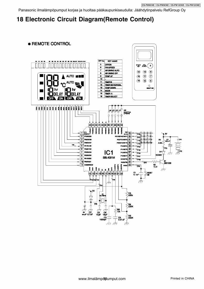
18 Electronic Circuit Diagram(Remote Control)
65
CS-PW9CKE / CU-PW9CKE / CS-PW12CKE / CU-PW12CKE
Printed in CHINA
Panasonic ilmalämpöpumput korjaa ja huoltaa pääkaupunkiseudulla: Jäähdytinpalvelu RefGroup Oy
www.ilmalämpöpumput.com