panther series owner’s manual - horsch · panther lighting wire summary chart ... adjusting...
TRANSCRIPT

1 | P a g e
HORSCH, LLC
200 Knutson St.
Mapleton, ND 58059
Telephone: (701) 532-1000
Fax: (701) 532-1101
Toll Free: 855-4HORSCH
Email: [email protected]
Web: www.horsch.com
Panther Series Owner’s Manual
2013
Serial Numbers: PPS440 SN Earlier – 110044012001 PPS460 SN Earlier – 110046013022
440/460
HORSCH, LLC
200 Knutson St.
Mapleton, ND 58059
Telephone: (701) 532-1000
Fax: (701) 532-1101
Toll Free: 855-4HORSCH
Email: [email protected]
Web: www.horsch.com

2 | P a g e

3 | P a g e

4 | P a g e
Contents Introduction .................................................................................................................................................. 8
Machine Registration .................................................................................................................................... 8
Warranty Guidelines ..................................................................................................................................... 9
Machine Registration Form: Customer Copy .............................................................................................. 11
Machine Registration Form: Dealer Copy ................................................................................................... 13
Machine Registration Form: HORSCH’s Copy ............................................................................................. 15
Delivery Form: DEALERS’s Copy .................................................................................................................. 17
Product Specification .................................................................................................................................. 19
In These Operating Instructions .................................................................................................................. 20
Authorized Operators ............................................................................................................................. 20
Protective Clothing ................................................................................................................................. 20
Safety .......................................................................................................................................................... 21
Understand Safety Symbols .................................................................................................................... 21
Safety Symbols on the Machine: ............................................................................................................ 22
Operational Safety .................................................................................................................................. 23
Road Traffic & Transport Safety .................................................................................................................. 25
Accident Prevention ................................................................................................................................ 27
Hitching/Unhitching ................................................................................................................................ 27
Changing Implements ............................................................................................................................. 28
In Operation ............................................................................................................................................ 28
Extracting Stuck Machine Safety & Guidelines ....................................................................................... 29
Service and Maintenance........................................................................................................................ 29
Installation .................................................................................................................................................. 30
Connecting Hydraulics to Tractor ............................................................................................................... 31
Wiring Solutions .......................................................................................................................................... 32
Configuration and Mode of Operation ....................................................................................................... 33
Transportation & Installation ...................................................................................................................... 36
Transportation ........................................................................................................................................ 36
Attaching the Air Seeder ......................................................................................................................... 37
Connecting the Hydraulic System ........................................................................................................... 37

5 | P a g e
Wing Section Folding .............................................................................................................................. 38
Connect the Road Lighting System ......................................................................................................... 39
Panther Lighting Harness .................................................................................................................... 39
Panther Lighting Schematic ................................................................................................................ 40
Panther Lighting Wire Summary Chart ............................................................................................... 41
Parking the Air Seeder ............................................................................................................................ 42
Adjustment/Operation ........................................................................................................................... 42
Manifold System ..................................................................................................................................... 45
Planting Systems Settings on Corn .......................................................................................................... 49
Agronomic Tips ....................................................................................................................................... 53
Depth Setting .......................................................................................................................................... 55
Basic Setting ............................................................................................................................................ 55
Adjusting Casting Tower Brake Assembly (ATD 60-15 & 40-15 only) ..................................................... 57
Setting the Seeding Depth ...................................................................................................................... 58
Timing of the Front Hitch ........................................................................................................................ 62
Checking the Seed Depth of the Machine .............................................................................................. 63
Checking for Seed ................................................................................................................................... 63
Machine Work Instructions..................................................................................................................... 65
Check Points ............................................................................................................................................ 65
Air Seeder: ........................................................................................................................................... 65
Cultivation Tools: ................................................................................................................................ 65
Fan: ...................................................................................................................................................... 65
Pneumatic System: .............................................................................................................................. 65
Rephasing the Hydraulic Cylinders ......................................................................................................... 66
Disc Leveler ............................................................................................................................................. 67
Rear Drawbar .......................................................................................................................................... 67
Hydraulic Cylinders ................................................................................................................................. 67
Openers ....................................................................................................................................................... 71
Maintenance ............................................................................................................................................... 73
Hitch Adjustment & Maintenance .......................................................................................................... 78
Maintenance Schedule ............................................................................................................................... 80
Overview of Lubricating Points ............................................................................................................... 81

6 | P a g e
Troubleshooting .......................................................................................................................................... 85
Service & Information ................................................................................................................................. 86
Metric Bolt & Screw Torque Values ........................................................................................................ 86
Unified Bolt & Screw Torque Values ....................................................................................................... 87
Metric Conversions ................................................................................................................................. 88
Hydraulic Schematic – Lift (ATD 60-15/Panther 460 shown) ................................................................. 89
Hydraulic Schematic – Fold (ATD 60-15/Panther 460 shown) ................................................................ 90
Notes: .......................................................................................................................................................... 93

7 | P a g e

8 | P a g e
Introduction Safety is YOUR responsibility!
READ AND UNDERSTAND THIS MANUAL BEFORE YOU OPERATE THIS MACHINE.
Learn how to operate and service your machine correctly. Failure to do so could result in personal injury and/or equipment and property damage. HORSCH will not accept any responsibility for any damage or malfunctions resulting from failure to comply with the Operator’s Manual.
If the information found in this manual is not completely understood or if there are any questions, contact HORSCH Customer Service.
HORSCH cares about your safety! This machine is designed to provide maximum possible safety; but no machine design can prevent operator error or carelessness.
The Operator’s Manual provides instructions for the safe operation and maintenance of this machine.
Make sure the machine is in good operation condition.
Check service schedule in book.
This manual should be considered a permanent part of your machine and should remain with the machine if you no longer own it.
Right hand and left hand are determined by facing the direction of forward travel respectively.
HORSCH reserves the right to alter illustrations as well as technical data and weights contained in this manual at any time without notice.
This data is the property of HORSCH. All use and/or reproduction not specifically authorized by HORSCH are prohibited.
All information, illustrations and specifications in this manual are based on the latest information available at the time of publication. The right is reserved to make changes at any time without notice.
Some illustrations may show optional equipment. Illustrations may show shields, guards, etc., opened or removed. All shields, guards, etc. must be in place during operation.
Machine Registration Please complete the Machine Registration Form on the next few pages and return to HORSCH. Accurately record all the numbers to help in tracing the machine. Your dealer needs these numbers when you order parts. NO WARRANTY CLAIMS WILL BE ACCEPTED IF THIS MACHINE REGISTRATION IS NOT RETURNED. The warranty period begins on the date of delivery.

9 | P a g e
Warranty Guidelines 1. The period of warranty for material defects relating to HORSCH products will be 12 months. In the case of written deviations from the statutory provisions, these agreements shall apply. They shall become effective upon delivery of the machine to the end customer. All wear item parts are excluded from the warranty. These parts include but are not limited to disc blades and Rollflex packer tongues. 2. Warranty claims must be submitted to the HORSCH Customer Service Department in Andover, SD via your dealer. It is only possible to process claims which have been completed correctly and submitted no later than four weeks after the damage occurred. 3. In the case of deliveries made under the warranty which are subject to the return of the old parts, the warranty claim, together with the old parts, must be returned to HORSCH within 4 weeks after the damage occurred. 4. In the case of deliveries made under the warranty, which are not subject to the return of the old parts, these parts must be kept for the purpose of further decisions for a period of four weeks after receipt of the warranty claim. 5. Warranty repairs to be carried out by outside companies, or repairs which are expected to take more than 2 working hours, must be approved in advance with HORSCH Customer Service Department.
HORSCH, LLC 200 Knutson St. Mapleton, ND 58059 701-532-1000 [email protected]
www.horsch.com For other related warranty items such as tire warranty issues, contact your nearest dealer.
A complete list of dealers can be found at the following web sites.
Firestone Tires - http://www.firestoneag.com/default-eng.aspx or 1-800-435-4437.
Titan Tires - http://www.titan-intl.com/ or 1-800-USA-BEAR.

10 | P a g e

11 | P a g e
Machine Registration Form: Customer Copy No Warranty Claims will be accepted if this Machine Registration Form is not returned! To: HORSCH, LLC 200 Knutson St. Tel: 701-532-1000 Email: [email protected] Mapleton, ND 58059 Fax: 701-532-1101 Machine Product & Model: __________________________ New Machine Final Sale – Initial use
Customer’s Machine – Transfer
Serial Number: ___________________________________ Demonstration Machine – Initial use Sold Date: _______________________________________ In Service Date: Est. Acres: ____________________ Operating Instructions: I hereby confirm receipt of the Owner’s Manual and Parts Catalog for the above mentioned machine. I have been instructed and informed by a HORSCH factory trained Service Technician / authorized Dealer representative in the operation and functions of the machine, as well as in the safety requirements. ________________________________________________ Name of the Service Technician / Dealer representative Dealer Customer Name: ______________________________ Name: _______________________________________ Address: ____________________________ Address: _____________________________________ City/State/Zip: ________________________ City/State/Zip: _________________________________ County: _____________________________ County: ______________________________________ Tel: ________________________________ Tel: _________________________________________ Fax: ________________________________ Fax: ________________________________________ E-mail: ______________________________ E-mail: ______________________________________ Customer No: _________________________ Customer No: _________________________________ I am aware that a Warranty Claim will only be valid if, after the receipt of the machine, this form has been fully completed, signed and returned to HORSCH, LLC. ______________________________________ ______________________________________ Place, Date Customer’s Signature NOTE: After Signing, remove and/or copy this page. Keep signed delivery checklist in machine file at the dealership.

12 | P a g e

13 | P a g e
Machine Registration Form: Dealer Copy No Warranty Claims will be accepted if this Machine Registration Form is not returned! To: HORSCH, LLC 200 Knutson St. Tel: 701-532-1000 Email: [email protected] Mapleton, ND 58059 Fax: 701-532-1101 Machine Product & Model: __________________________ New Machine Final Sale – Initial use
Customer’s Machine – Transfer
Serial Number: ___________________________________ Demonstration Machine – Initial use Sold Date: _______________________________________ In Service Date: Est. Acres: ____________________ Operating Instructions: I hereby confirm receipt of the Owner’s Manual and Parts Catalog for the above mentioned machine. I have been instructed and informed by a HORSCH factory trained Service Technician / authorized Dealer representative in the operation and functions of the machine, as well as in the safety requirements. ________________________________________________ Name of the Service Technician / Dealer representative Dealer Customer Name: ______________________________ Name: _______________________________________ Address: ____________________________ Address: _____________________________________ City/State/Zip: ________________________ City/State/Zip: _________________________________ County: _____________________________ County: ______________________________________ Tel: ________________________________ Tel: _________________________________________ Fax: ________________________________ Fax: ________________________________________ E-mail: ______________________________ E-mail: ______________________________________ Customer No: _________________________ Customer No: _________________________________ I am aware that a Warranty Claim will only be valid if, after the receipt of the machine, this form has been fully completed, signed and returned to HORSCH, LLC. ______________________________________ ______________________________________ Place, Date Customer’s Signature NOTE: After Signing, remove and/or copy this page. Keep signed delivery checklist in machine file at the dealership.

14 | P a g e

15 | P a g e
Machine Registration Form: HORSCH’s Copy No Warranty Claims will be accepted if this Machine Registration Form is not returned! To: HORSCH, LLC 200 Knutson St. Tel: 701-532-1000 Email: [email protected] Mapleton, ND 58059 Fax: 701-532-1101 Machine Product & Model: __________________________ New Machine Final Sale – Initial use
Customer’s Machine – Transfer
Serial Number: ___________________________________ Demonstration Machine – Initial use Sold Date: _______________________________________ In Service Date: Est. Acres: ____________________ Operating Instructions: I hereby confirm receipt of the Owner’s Manual and Parts Catalog for the above mentioned machine. I have been instructed and informed by a HORSCH factory trained Service Technician / authorized Dealer representative in the operation and functions of the machine, as well as in the safety requirements. ________________________________________________ Name of the Service Technician / Dealer representative Dealer Customer Name: ______________________________ Name: _______________________________________ Address: ____________________________ Address: _____________________________________ City/State/Zip: ________________________ City/State/Zip: _________________________________ County: _____________________________ County: ______________________________________ Tel: ________________________________ Tel: _________________________________________ Fax: ________________________________ Fax: ________________________________________ E-mail: ______________________________ E-mail: ______________________________________ Customer No: _________________________ Customer No: _________________________________ I am aware that a Warranty Claim will only be valid if, after the receipt of the machine, this form has been fully completed, signed and returned to HORSCH, LLC. ______________________________________ ______________________________________ Place, Date Customer’s Signature NOTE: After Signing, remove and/or copy this page. Keep signed delivery checklist in machine file at the dealership.

16 | P a g e

17 | P a g e
Delivery Form: DEALERS’s Copy At the time the machine is delivered, the following checklist is a reminder of information which should be conveyed directly to the customer. Check off each item as it is fully explained to customer. [ ] Make the customer aware of all safety precautions that must be exercised while using this
machine. Point out all Warning and Caution safety labels/decals on the machine. [ ] Point out the location of the Serial Number Tag (product identification numbers), for future
reference of the machine. [ ] Give the Operator’s Manual to the customer. Encourage customer to read the manual in its
entirety. [ ] Explain all operating adjustments. [ ] Review recommended procedures for attaching and detaching machine from tractor. [ ] Make the customer aware of all safety precautions that must be observed when transporting
the machine in field and on public roads. [ ] When the machine is transported on a road or highway at night, or during the day, accessory
lighting and devices should be used for adequate warning to operators of other vehicles. In this regard, tell the customer to check local governmental regulations. The machine should be equipped with road lighting and slow moving vehicle sign.
[ ] Explain to the customer that the life expectancy of this or any other machine depends on
regular lubrication as directed in the Operator’s Manual. Follow all maintenance and lubrication schedules for the machine.
[ ] Discuss with the customer the use of proper tools and equipment for service of the machine. [ ] Have customer record Serial Number(s) in the Product Specification section. [ ] To the best of my knowledge, this machine has been delivered ready for field use and the
customer has been fully informed as to proper operation and care. Signed: ................................................................................. (Customer)
Signed: ................................................................................. (Dealer Representative)
Date: .....................................................................................

18 | P a g e

19 | P a g e
Product Specification Each machine manufactured and assembled is serialized and provided a number for tracking purposes. There is a model number, which is the category for product family of the machine, and there is a serial number.
The serial number may also be known as, or part of, a Product Identification Number. This number is a formulated number which details the machines build information for tracking purposes and easy identification later during time of service, maintenance and replacement part ordering. The Serial number, along with Model number of the machine, can be found on the Serial Number Tag.
HORSCH LLC has placed a Serial Number Tag (reference picture below) on the machine with the above mentioned information. It is located on the main frame cross member tube directly behind the front hitch, just off center towards the left hand side of each machine.
Record the Model and Serial number of the machine below. Retain this page for customer use only! For future reference, the information will be used whenever the machine is being serviced, for ordering replacement parts or when requesting information for the machine such as replacement Owner’s Manual or a Parts Catalog. Be sure to provide both, the model number and serial number, when contacting your dealer, for better assistance and quicker support of your machine.
HORSCH, LLC Serial Number Tag
Date of Purchase: ___________________________
Dealer Information:
Name: ______________________________
Address: _____________________________
Phone: _______________________________

20 | P a g e
In These Operating Instructions The operating instructions distinguish between three different types of warning and safety instructions. The following graphic symbols are used: Important instructions!
If there is a risk of injury!
If there is a risk to life and limb!
It is important that all the safety instructions contained in these operating instructions and all the warning signs on the machine are read thoroughly and understood prior to operation of the machine. Ensure that the warning signs are legible and replace any signs that are missing or damaged. These instructions must be followed in order to prevent accidents. Inform other users of the warnings and safety instructions and the location of this Owner’s Operators Manual. Do not carry out any operations which may affect the safe use of the machine.
Authorized Operators Only those persons who have been authorized and instructed by the operator may operate the Machine. Operators must be at least 16 years of age. The operator must hold a valid driving license. They are responsible for third parties in the operating area. The person in charge must:
• Make the operating instructions available to the operator. • Ensure that the operator has read and understood the operating instructions.
The operating instructions are a component part of the machine.
Protective Clothing For operation and maintenance of this machine, you will need:
• Snug fitting clothing; no loose articles or strings. • Safety gloves and goggles to protect against dirt and sharp edged machine parts.

21 | P a g e
Safety Information Regarding Safety The following warnings and safety instructions apply to all sections in these operating instructions. Carefully read all safety messages in this manual and on the machine safety decals. Keep safety decals in good condition. Replace missing or damaged safety decals. Be sure new equipment components and repair parts include the current safety decals.
Understand Safety Symbols

22 | P a g e
Safety Symbols on the Machine:
Read and adhere to the operating instructions before starting up the machine!
Stay clear of swinging area of retractable and extendible machine parts!
Switch the engine off and pull out the key before starting maintenance and repair work! Never reach into areas where there is a risk of crushing, as long as parts could still be moving!
Watch out for fluids spraying out under high pressure, follow the operating instructions!
It is only permitted to remain in the danger zone if the safety support is in place!
When hitching up the drill and when operating the hydraulic system, no persons should be between the machines! No passengers are allowed to ride on the machine! Do not climb on rotatable parts. Use mounting steps provided for this purpose!
Lifting hook; attach lifting tackle (chains, ropes, etc.) here when performing loading work!

23 | P a g e
Operational Safety The machine must only be put into operation after receiving instructions by employees of the autho-rized dealer or a HORSCH employee. The Machine Registration Form is required to be completed and returned to HORSCH.
Do not make field adjustments while machine is in motion. Do not enter seed tank of cart unless another person is present and hydraulic hoses are disconnected from tractor. Operate machine from the tractor seat only. Keep hands and fingers away from hinge area when positioning fill auger. Lock auger in storage position before operating in field. Clear area around machine before raising or lowering machine or wings. Stop tractor on level ground when raising or lowering machine or wings. Do not operate with wings raised. To improve stability, travel through the field with the wings unfolded. Fold wings to transport position just before leaving the field and entering a roadway. Do not operate close to the edge of a ditch, creek, gully or steep embankment. Avoid holes, ditches and obstructions which may cause tractor, cart or seeding tool to roll over, especially on hillsides. Avoid sharp turns on hillsides. Slow down when turning or traveling over rough ground, and when turning on inclines. Shut off tractor and shift to ‘Park’ or set brakes when leaving tractor. Remove key when leaving tractor unattended. Stay Clear of Air Hoses
Stay clear of hoses when air seeder fan is running. Seed or fertilizer blowing out at high speed can cause eye and other personal injuries. Never attempt to clear blockage from air hoses or seeding tool boots while fan is running.

24 | P a g e
Use a Signal Person
Use a signal person to direct movement of the tractor/seed cart, seeding tool combination whenever the tractor operator’s view is obstructed.
Designate one individual as the Signal Person. Always have signal person stand in clear view. Be sure signal person stays a safe distance away from the machine when it is moving.
Prior to starting tractor, discuss hand signals and what each signal means to avoid misunderstandings and confusion which could result in a serious injury or fatal accident.
Keep all bystanders away whenever the machine is moved.
Do not stand between cart and implement while machines are in motion.
Wear Protective Clothing
Wear close fitting clothing and safety equipment appropriate to the job.
Operating equipment safely requires the full attention of the operator. Do not wear radio or music headphones while operating machine. This can impair the hearing of the operator and distract them from their surroundings which could lead to an accident.
Do not operate commodity cart without safety shields in place.

25 | P a g e
Rotating parts can crush or dismember, causing death or personal injury.
To avoid serious injury or death from entanglement, do not allow person(s) or clothing to be near auger when it is in motion.
Keep auger hopper screen in place.
Shut off tractor and disconnect hydraulic hoses before removing shields for adjustment or service.
Use a Safety Chain
A safety chain will help control drawn equipment should it accidentally separate from the drawbar. A safety chain of the proper strength rating is provided with the machine as standard equipment.
Using the appropriate adapter parts, attach the chain to the tractor drawbar support or other specified anchor location. Provide only enough slack in the chain to permit turning.
Road Traffic & Transport Safety The valid road traffic regulations are to be observed when travelling on public roads, paths and areas. Do not exceed the maximum permissible transportation widths and heights and install road lighting equipment, warnings and safety covers where necessary. Do not exceed the permissible axle loads, tire carrying capacities and total weights, in order to ensure sufficient steering and braking capabilities. Handling is affected by the implement connected. It is important to take into account the large overhang and the centrifugal mass of the implement, particularly when cornering. DO NOT EXCEED A MAXIMUM SPEED OF 20 MPH DURING TRANSPORTATION. LOSS OF VEHICLE/MACHINE CONTROL CAN RESULT IN SERIOUS PERSONAL INJURY OR DEATH!
The whole machine is to be cleaned of soil that has been collected before travel on public roads. Passengers are strictly forbidden to ride on the machine. Always travel at a reasonable and safe speed. Never exceed 20 mph. Never transport with any tank more than half full. Never transport with fan running.

26 | P a g e
Shift the tractor in to a lower gear when transporting down steep slopes or hills. Latch the tractor brakes together. Stop slowly. Avoid steep slopes. Some slopes may exceed tractor braking capability. Use engine braking to reduce speed when possible.
Keep away from overhead power lines. Serious injury or death may result. Proceed cautiously under overhead power lines and around utility poles. Know the transport height of your machine. Do not position auger when near electrical lines. Electrocution can occur without direct contact with overhead electric lines. Always fold wings fully. If wing fold cylinders are removed, chain wings together to prevent accidental lowering. Do not transport with an underweight tractor. Transport only with a properly sized tractor. Refer to ‘Calculating Minimum Tractor Weight for Safe Transport’. Use Safety Lights and Devices Prevent collisions between other road users, slow moving tractors with attachments or towed equipment and self-propelled machine on public roads. Frequently check for traffic from the rear, especially in turns, and use turn signal lights.
Use headlights, flashing warning lights, and turn signals day and night. Follow local regulations for equipment lighting and marking. Keep lighting and marking visible and in good working order. Replace or repair lighting and marking that had been damaged or lost.
Keep reflective material and Slow Moving Vehicle signs clean and visible.

27 | P a g e
Accident Prevention In addition to the operating instructions, it is important to observe the accident prevention regulations specified by agricultural trade associations! Hitching/Unhitching There is risk of injury to persons when hitching/unhitching the machine to the three-point hitching device of the tractor. Observe the following:
• Secure the machine against rolling away. • Take special care when reversing the tractor. Never stand between tractor and machine. • Only park the machine on a firm and level surface. • Always lower the front jack when you park the seeder and raise the jack when the seeder is in its
transportation position. Hitch Flipping Up (Applies to earlier ATD 40-15/60-15 Models only) Never unhook tractor from air seeder with front caster wheels in reverse position. Serious injury could result and damage to the machine could occur if caution is not taken to assure caster wheels are in forward position.
Panther 440/460 Models seeders front hitch/drawbar shown below with new design parallel arms.
* The parallel arms prevent the front hitch from flipping up. This design was introduced during mid-model generation of the ATD 40-15/60-15 model seeders.

28 | P a g e
Changing Implements
• Secure the machine against unintended and accidental rolling! • Secure lifted frame parts, under which you will be working, with suitable supports! • Caution! Danger of injury caused by protruding parts (tines, discs)! • Do not use the packer or other rotating parts when climbing onto the machine. These could start
to rotate and you could fall and be seriously injured. In Operation
• Check the area around the machine (for children!) before setting off and starting operation of the machine. Ensure sufficient visibility!
• Stay clear of the operating range of hydraulically operated parts. • Passengers are not allowed to ride on the machine during operation! • Do not stand on the machine when it is in operation. • The prescribed protective equipment that may have been supplied with the machine is not to be
removed.

29 | P a g e
Extracting Stuck Machine Safety & Guidelines Follow proper hooking and towing recommendations below for extracting stuck machines. If damage is incurred to a machine during extraction due to improper procedure, any applicable warranties may be void!
• Avoid wet, water logged and muddy ground conditions so as not to get stuck. • Assess the situation around the stuck machine before attempting extraction. • Know when to call a professional for assistance in towing, lifting and extraction. • Use properly rated equipment – larger tractor/truck, tow ropes/straps, clevises, chains, cables,
etc. • Practice proper hooking and pulling techniques. Know where proper hooking points are at on a
machine so as not to damage the machine. Do not hook or pull the machine from the transport axle or rear packer system. Attach to a tie down location or the main frame. Do not pull the machine sideways. Pull in a straight line as much as possible.
• Pull force should not exceed normal operating conditions. • Be aware of overhead power lines to avoid risk of serious damage and/or personal injury. • Be aware of ditches or rocks to avoid tipping hazards of equipment. • All bystanders are at risk of serious injury and must stand clear of extraction area for their own
personal safety. • Inspect machinery after recovery. Make any necessary repairs before putting the machine back
into service.
Service and Maintenance
• Ensure that regular tests and inspections are always carried out to schedule, as specified in the operating instructions.
• Prior to performing maintenance and servicing work, ensure that the machine is positioned on firm, level ground and that it is properly secured against rolling away.
• Prior to working on the electrical system, disconnect it from the electric power supply. • Retighten screwed connections which had been loosened during servicing and maintenance work. • For further Service and maintenance information see other sections in this manual; Maintenance
& Service & Information.
Do not wash new machines with a steam-jet or high-pressure cleaner. The paint takes approximately 3 months to cure and could thus be damaged if this time has not yet expired.

30 | P a g e
Installation Instruction of the operator and initial installation of the machine are done by an authorized dealer or HORSCH representative.
The machine can be released for operation only after instruction by our service technician or authorized distributor has been completed and the operating instructions have been read and understood.
When carrying out installation and maintenance work there is a higher risk of injury.
It is important that you familiarize yourself with the machine and read this Owner’s Manual before operating the machine.
The instructions in respect of initial installation should also be followed if the machine has not been used (stored) for a longer period of time. Dismantle the removable parts supplied with the machine.
• Check all important screw connections. • Grease all zerks. • Check air pressure in tires. • Prepare connection for the lighting equipment. • Check all hydraulic connections and hoses for correct attachment and proper functioning. • Ensure that any deficiencies are remedied immediately.
Hydraulic Functions When handling the machine, ensure that nobody is in the danger zone.
The hydraulic functions are controlled at tractor hydraulic controls from inside the cab.
Safety Measures in Case of Injury from Oil Eyes: Should any oil be splashed into your eyes, rinse with water for 15 minutes. If the eye is still irritated, contact a doctor immediately.
If Oil is Ingested: If oil is swallowed, it is important not to induce vomiting. Contact a doctor immediately.
Skin Irritation caused by Oil: In case of prolonged skin contact, wash off the oil with soap and water.
Oil Spills: Use either sand or a suitable granular absorbent to soak up any spilled oil. Dispose of the oil contamination absorbent in the proper manner.
Oil Fires: Never use water to extinguish an oil fire. The oil will float on water causing the fire to spread. Burning oil-lubricant must be extinguished using a carbon dioxide power or foam extinguisher. Always wear respiratory equipment when dealing with fires of this type.
Waste Oil Disposal: Oil-contaminated waste and used oil must be disposed of in accordance with current legislation. Check with your local hazardous waste management coordinator. Waste oils must be collected and disposed of with local regulations. Never pour used oil in to a sewage system or drains or on to the ground.

31 | P a g e
Connecting Hydraulics to Tractor

32 | P a g e
Wiring Solutions
IMPORTANT! The electronics must be hooked to battery power. Never connect to the starter.

33 | P a g e
Configuration and Mode of Operation Description The Panther 440 and 460, along with the ATD 60-15 and 40-15 Air Seeders, are usually used with a seed wagon after minimal cultivation.
Triple Shoot Openers are used together with a fertilizer seed wagon. Here it is possible to apply the fertilizer accurately using an electronically controlled device, which enables it to be placed below the seed during sowing.
The specified amount of seed/liquid fertilizer can be discharged at speed according to the drill management system settings in the ECU (Electronic Control Unit) in the tractor.
Depending upon the seed cart type, the 60-15 and 40-15 planting system can be operated in front of or behind, hitched up to the back of the seed wagon. The picture below illustrates the air seeder in front of the seed wagon.
The Panther air seeder can be used to seed all seeds with a grain size of between 0.040” – 0.39”.
Grain: Wheat, barley, oats, rye, sorghum.
Large Seeds: Peas, beans, soybeans, sunflowers.
Small Seeds: Grass, clover, alfalfa, rapeseed.
IMPORTANT! When transporting on public roads, the seed cart must be empty. With the seed cart hitched to the rear of the air seeder, central packer tires can fail due to increased weight transferred from a loaded/partially loaded seed cart.

34 | P a g e
The Triple Shoot Opener carbide tip cultivates the soil.
The fertilizer is placed in the soil through a stainless steel pipe from behind the tip.
The angled triangular baseplate divides and levels the seedbed over the liquid fertilizer.
The fertilizer binds with the soil which is then covered and firmed.
The Triple Shoot Opener wear plates open up the seed channel and the distributor deposits the seed over the required width.
Due to the shape of the opener, precise placement of the seed is ensured and it is prevented from being blown out of the furrow.
Changing the Triple Shoot Opener The point of the opener is secured with a steel roll pin. The opener point is not to be struck when changing the points and driving in the roll pin. If the point is struck it may fracture, therefore, the use of an appropriate tool and device is required.
The baseplates are fastened with either 5/16”-18 hex bolts or 3/8”-16 hex bolts on later models of openers. Either a ½” or 9/16” wrench, and a 7/32” hexagon socket screw key (Allen wrench), are needed for the repair work.
Anderson Single Shoot Opener The Single Shoot Opener was developed for sowing leguminous plants and soybeans as these seed types require a loose seed bed around the seeding.

35 | P a g e
Coulter Operation The cutting coulters may be operated in three different settings:
1. Top – the coulter blade is just even with the opener knife tip. This is the proper settings to run in most field conditions. As wear occurs on the blade the coulter may be set in to the middle setting.
2. Middle – as wear occurs on the coulter blade this setting is 1.5” lower. 3. Bottom – used when the coulter blade is nearing the end of its working life.
Coulter Adjustment The cutting coulters are preassembled and adjusted from the factory. However, adjustment to spring tension is available and may be necessary.
1. Set spring tension by adjusting the ¾” lock nut until the spring is compressed to a length of 8-3/4”. This should be the minimum set pre-load for this spring. If the spring can be rotated on the push rod by hand, it is too loose and must be tightened.
2. Tighten 3/4” lock nut if greater spring pre-load is required, depending on field conditions and desired seed depth.
3. Inspect the spring for pre-load before each operation. Maximum spring pre-load is up to 1-1/4” of thread exposed from the lock nut.
NOTE: Replace any damaged or broken springs or other components immediately. For a complete list of serviceable items, see Panther Planting System Parts Catalog, or your nearest authorized HORSCH dealer.
Picture to right indicates an assembled coulter unit with spring installed and pre-load set to the minimum setting, (8-3/4”).
The ¾” lock nut is installed and tightened against the outer coil spring keeper.

36 | P a g e
Transportation & Installation Transportation
The air seeder may only be towed when the cart hopper is empty. The maximum speed is 20 mph.
• Hitch the air seeder to the tractor. • Connect the hydraulic system. • Fold the wings of the frame and secure. • Connect the lighting equipment. • Raise the jack when the machine is lifted and locked and move the jack to its transport position. • Slide spacers on the lifting cylinders and lower the machine. • Pay attention to the height and width of the machine during transportation.
DO NOT EXCEED A MAXIMUM TRANSPORTATION SPEED OF 20 MPH (32 KPH) DURING TRANSPORTATION. LOSS OF VEHICLE/MACHINE CONTROL CAN RESULT IN SERIOUS PERSONAL INJURY OR DEATH!
Front Hitch decal
37 | P a g e
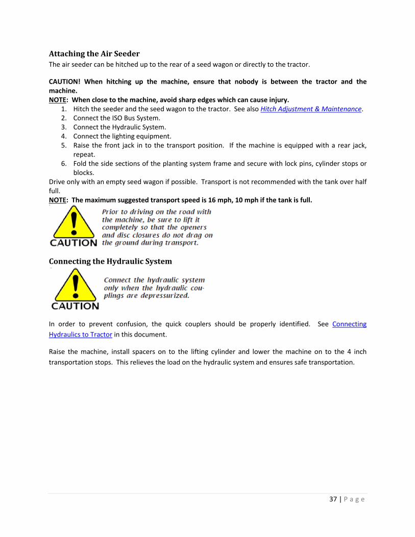
Attaching the Air Seeder The air seeder can be hitched up to the rear of a seed wagon or directly to the tractor.
CAUTION! When hitching up the machine, ensure that nobody is between the tractor and the machine. NOTE: When close to the machine, avoid sharp edges which can cause injury.
1. Hitch the seeder and the seed wagon to the tractor. See also Hitch Adjustment & Maintenance. 2. Connect the ISO Bus System. 3. Connect the Hydraulic System. 4. Connect the lighting equipment. 5. Raise the front jack in to the transport position. If the machine is equipped with a rear jack,
repeat. 6. Fold the side sections of the planting system frame and secure with lock pins, cylinder stops or
blocks. Drive only with an empty seed wagon if possible. Transport is not recommended with the tank over half full. NOTE: The maximum suggested transport speed is 16 mph, 10 mph if the tank is full.
Connecting the Hydraulic System
In order to prevent confusion, the quick couplers should be properly identified. See Connecting Hydraulics to Tractor in this document.
Raise the machine, install spacers on to the lifting cylinder and lower the machine on to the 4 inch transportation stops. This relieves the load on the hydraulic system and ensures safe transportation.

38 | P a g e
Wing Section Folding The folding action on the side wings are connected to double-acting cylinders.
Do not stand in the area around the folding sections.
Folding:
1. Raise the air seeder to its up position. Install 4” cylinder stops on main frame, lower down on stops and inner wings.
2. Activate control lever and gradually fold the outer wings and inner wings. 3. Attach the folding safety bolts.
Unfolding:
1. Remove the folding safety pins for unfolding. Serious damage may occur if safety pins are not removed before beginning to unfold.
2. Select valve connected to wing fold and begin unfolding when inner wings have completely unfolded and cylinders are starting to extend in the slot of the inner wing. Reverse hydraulic flow to unlock wing hooks. At this time the outer wings will drop down on the top of the inner wings and the wing hooks will fall away allowing the outer wings to unfold.

39 | P a g e
Connect the Road Lighting System Connect the 7-pin lighting system plug to the socket on the tractor.
Before transporting the air seeder on public roads, it is important to check the function of the lighting and the condition of the red tail lights and amber flashing lights. Repair all lights that are not functional before transporting.
Panther Lighting Harness
40 | P a g e
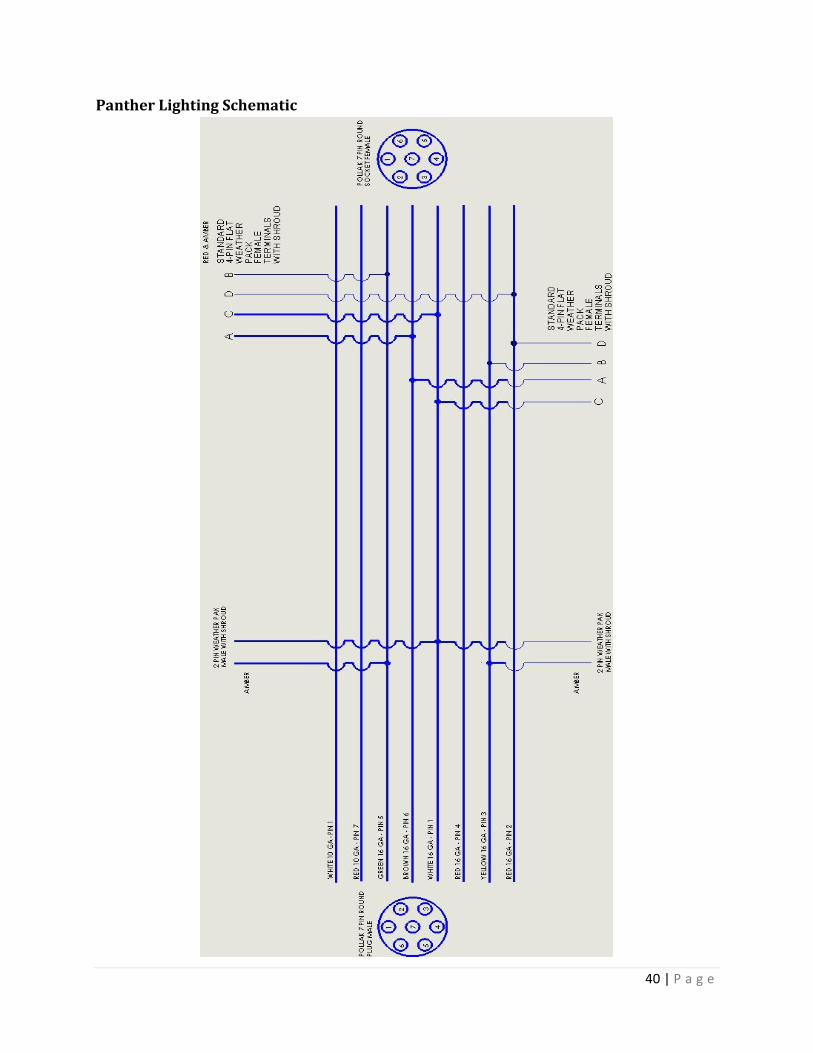
Panther Lighting Schematic

41 | P a g e
Panther Lighting Wire Summary Chart

42 | P a g e
Parking the Air Seeder The air seeder should be parked indoors or under cover whenever possible to prevent moisture collecting in the distributor, metering units, or seed tubes.
The Panther air seeder can be parked separately or together with the seed wagon.
This prevents the drawbar from tilting upwards when it is unhitched.
When maneuvering the air seeder, pay attention to your surroundings. Ensure that nobody is in the maneuvering area.
1. Park the seeder on level and solid ground. Switch off the tractor. 2. Lower the air seeder to the ground and position the seeder stabilizer in the park position. 3. Disconnect the tractor hydraulic and electric systems and hook them on the brackets of the
machine. 4. Move and lower the jack to the lift position. Unhitch the seeder from the tractor by removing
the draw pin. 5. Empty the distributor. 6. Clean the metering units. 7. Close the distributor cover. 8. Store electrical and electronic components in a dry storage area until next use.
Adjustment/Operation Walking Tandem Packer Wheels
The packers are made up of several flexing sections.
The packer consolidates the soil and leaves a level and water permeable seedbed.
In the transportation position the center packer acts as a chassis. The two outer packers are folded and the center pack supports the machine.

43 | P a g e
The soil must be uniformly consolidated over the entire working width. It is important to keep a constant and proper air pressure in the packer tires for best operation and uniformity. Tire inflation pressure 30 psi minimum.
Adjustable Link
Checking/Maintenance:
The factory settings on the packer top links do not usually need to be adjusted.
Check the tightness of all the top link counternuts (upper link) regularly.
• Check the tightness of the wheels and flange bearings. • Check the tightness of the screw connections and setting spindles. • Check the air pressure:

44 | P a g e
o Outer packer: approx. 25-30 psi. o Inner packer: approx. 30 psi.
• Check tires for damage.
Panther 440/460 rear packer linkage and lift system

45 | P a g e
Manifold System The manifold heads provide the air and seed to the openers. Double shoot systems have four manifold heads, while single shoot only have two manifold heads.
If a 24/12 manifold lid is used, it is important to distinguish between the hoses which are connected to the open outlets and those which are connected to the sealed outlets. Align arrow when installing 24/12 lids.
The seed flow monitoring sensors are mounted on the distributor exit.
The manifold heads are lowered automatically when the air seeder is folded and raised again when the machine is unfolded. This avoids damaging the manifold head and creates enough space for folding.
It may be necessary to readjust the yoke height when carrying out repairs on the manifold heads.

46 | P a g e
Maintenance:
The manifold heads must be checked for foreign material at regular intervals. Foreign material disturbs the seed flow product distribution, and the operation of the sensors.
The hoses and manifold lid must be firmly attached and sealed. Any air leaks will result in uneven seed distribution and blocked seed hoses.
The seed hoses must not be allowed to sag. Tie them up out of harm’s way so as not to get damaged. And the inside of the hoses must be kept dry, even when the machine is not used for long periods of time.
Installation of 32-16 or 24-12 Reduction Lid

47 | P a g e

48 | P a g e
Setup for Corn Planting:
Using the AE-15 Double Shoot Opener with NH3 system, you can plant the corn in paired rows and put the NH3 below the seed in 30” rows. The seed corn best recommended for us is a medium round size seed.
Mid Banding NH3:
Using the AE-SS Liquid or NH3 Opener you will be able to incorporate NH3 between the 30” rows for later use during the growing season.
See the following information for setting up seeder for 30” rows.
Tips for Planting Corn:
1. Installation of 24-12 or 32-16 manifold reduction lids. 2. Corn seed selection (Medium Rounds are best recommended). 3. The corn air stream should have the starter mixed with the corn so the product volume is larger
for better distribution. 4. It is advised to use the triple shoot opener on the rows planting corn so that in the case of two
seeds coming up the air stream they have a chance to be spread 7.5” to reduce double seeds. 5. Seed sensors not in use should be cancelled. 6. Seed and starter fertilizer are in one air stream so now you are seeding with 24-30” or 16-30”
rows. The nitrogen source however should be on all 48 or 16 rows to lower the concentration of fertilizer on the row. It is suggested that the single shoot opener be used on the mid-row opener.
7. Mid-row fertilizer is a huge benefit as corn plants use late season mid-row fertilizer. This technique could reduce the nitrogen requirement per bushel of production.
8. Calibration should be done by referring to the seed weight of the corn and calibrated in grams. Seed counting sensors will not work due to the fertilizer in the air stream with the corn. It is advised to put one bag of corn seed in the seed tank at a time. Then perform the calibration. After calibration, seed out the corn in the tank and check the cares covered.
9. Make sure to use the seed check process when calibrating for corn. 10. Corn should be planted at least 1.5 -2 “ deep. Corn seed takes more soil moisture to germinate
due to the size of the seed. 11. High speed seeding is not recommended on corn.
NOTE: Planting corn with any air seeder planting system will not have the picture perfect singulation of an actual corn planter. The newer corn genetics will somewhat compensate for this, however, even emergence, is the most important issue and goal to achieve.

49 | P a g e
Planting Systems Settings on Corn • Seed Selection • Weights and Measures • Calibrating Machine • Drill Configuration • Agronomic Tips
Seed Selection:
When making your seed corn selection, the following considerations should be taken:
Weights and Measures:
• Seed Corn must be Medium Rounds. • Population must be established. • Identify number of seeds per pound (located on
seed bag or container).
• On most bags and containers there should be a weight listing. • Locate this information as shown in the picture. • This information will be used to calibrate the machine for your
specific population. • 1277 seeds per pound. • 63.00 lbs. per bag. • 80,000 seeds per bag.

50 | P a g e
Machine Calibration:
Drill Configuration:
• Blue Meter Roller • Used for higher population rates
• Red Meter Roller • Used for lower population rates
• Remove top cover and dampener pad from stainless steel manifold.
• Remove cover plate.
• 30” Row Crop insert.
• Inspect manifold head to check for any wear or damage.
• Clean manifold area.

51 | P a g e
• Make sure to line up timing marks on insert and manifold.
• Once manifold is inspected and time marks identified, place insert in manifold head.
• Use a Double Shoot paired row opener when planting corn.
• Paired row opener will divide the seed row thus helping eliminate doubles.
• Model opener recommended: AE-15.
• Use the Single Shoot, reverse drop for dry, liquid or anhydrous.
• Use AE-SS Liquid or NH3 models if necessary.
• Mid row fertilizer is a huge benefit in late season growth.
• A Double Shoot system can be configured to apply in row and mid row bands of fertilizer.
• Use a Single Shoot reverse drop opener (shown above) for mid row shanks.

52 | P a g e
Every other sensor has to be bypassed starting with sensor # 1. All odd numbered sensors are bypassed. This insures no fault codes on monitor of tubes not used.
• Sensors have to be configured for 30” row application.
• Unplug Sensor 1.
• Plug Sensor 1 ends together. • Attach lead cable to sensor 2.
• Unplug Sensor 3. • Plug ends together. • Connect Sensor 2 with Sensor
4. • Continue bypassing using this
method.
• For easier configuration of drill, install the secondary manifold guide decal. This allows easy location of ports.

53 | P a g e
Agronomic Tips • The corn air stream should have the started mixed with the corn for better product distribution. • Use medium round seeds. • Set drill to plant 1.5-2” deep. • High speed planting is not recommended. • Make sure to use the seed check process when calibrating for corn. • Seed sensors not in use should be cancelled. • Proper calibration should be done before planting.
NOTE: Like any air seeder planting system, you will not have the picture perfect singulation of a regular corn planter. By using the paired row openers, seed will be spaced with limited doubles. The true measure of a planting system is the total bushels produced at harvest. With the Horsch Panther 60-15 or 40-15 air seeder, you will give your crop the best possible start of any system. For more details on the features of our planting systems, contact your local Horsch dealer at http://www.horschanderson.com/locate-a-dealer.html.

54 | P a g e

55 | P a g e
Depth Setting When in operation, the air seeder is supported by 12 hydraulic cylinders which raise the machine for sowing.
The rear main cylinders divide the lift hydraulic system in to two separate circuits. In each circuit all the cylinders are arranged in series.
The diameter of each following (series) cylinder is smaller to enable the lifting distance to remain constant across the entire working width.
Each cylinder is filled through a rephasing orifice which also compensates for any leaks.
In the extended position the rephasing orifice are exposed to allow the oil to flow into the next cylinder. The cylinders are filled with oil, vented and aligned with the end stop.
The cylinders are balanced automatically as soon as the control device is activated for a longer period during lifting. This should be done several times a day in order to ensure that the machine is always raised and lowered evenly. For more information see ‘Rephasing the Hydraulic Cylinders’ further in this section.
NOTE: It is necessary to rephase the cylinders before adjusting the depth.
Basic Setting The basic frame settings are adjusted from the factory. This involves adjusting the cylinder piston bosses and brackets to create an even gap between the frame and the ground so as to achieve a level setting at both the front and rear using the cylinder spacers.
Check Basic Setting:
1. Check the air pressures on the caster tires and packer tires and inflate to recommended pressure noted in this manual if necessary.
2. Hitch up the machine and unfold it on level ground. 3. Raise the air seeder and level off the cylinders. 4. Place identical combinations and equal number spacers on the hydraulic cylinders for the depth
guide. 5. Lower the air seeder until it is just off the ground. The openers should all be at approximately
the same height. The cylinders should be flush against the spacers on all the connecting rods. 6. Adjust the connecting rods and mounting plates if necessary.
* All other adjustments are made in the field. Further information is detailed in ‘Setting the Seed Depth’ explained in this section.

56 | P a g e
• Every step on the depth stop chart moves the air seeder approximately 0.31” or 5/16” either up or down.

57 | P a g e
Adjusting Casting Tower Brake Assembly (ATD 60-15 & 40-15 only)
NOTE: Reinstall cap with pressure disk, foam ring and desired shim rings.

58 | P a g e
Setting the Seeding Depth To adjust the depth, remove the same number and color combinations of spacers from all the depth guides.
The ratio is approximately 2:1.
Adjusting the connecting rod 1” alters the heights of the machine by approximately 2”.
The various spacer combinations (see diagram on hydraulic cylinder) enable the height to be adjusted by approximately 0.31” at each level (as described on previous pages).
Remove spacers to adjust the machine to the desired working depth.
First, you must check phase of the hydraulic cylinders to determine proper lift. Follow the procedure, ‘Rephasing the Hydraulic Cylinders’ in this section.
Procedure:
1. It is best recommended after rephasing the lift cylinders the machine be leveled. Before using the machine in field operation, find a hard, flat surface such as a concrete slab. Unfold the machine. Lift the machine up completely to be certain it is phased. Then lower the machine 3/4"-1”. You must use some of the depth stops provided with the machine. With the machine opener tips now 3” from the ground from high lift, measure for levelness across the machine.
2. The main frame of the seeder is your starting point. ALWAYS START FROM THE MIDDLE OF THE MACHINE AND WORK YOUR WAY OUTWARD TO THE OUTER WINGS (WHERE EQUIPPED). Work front to back, center to outer wings. Adjust the front, then the back. The front of the machine has been set from the factory to the center position. For now this will be our predetermined depth setting.
3. Use the diagrams on the following pages for reference. From location 1 (front hitch drawbar), find the nearest opener on the left hand side and measure from tip to the ground. Record your measurement in the chart. Then measure the opener closest to the adjustment plate on the right hand side and record its measurement. Next, move to location 2 and repeat the procedure. Record measurements.
4. To adjust depth, loosen the clamping bolts (x4), see pictures on the next page. Then loosen the jam nut of the adjusting bolt on the appropriate adjustment plate. Use the opposite jam nut, by threading in/out, to adjust the height on that corner location. Remember the 2:1 ratio, an adjustment of ½” adjusting bolt thread will adjust the machine height by 1”. Repeat for each of locations 1 and 2 to adjust accordingly. Measure each opener tip point again for verification and adjust as needed. When done be sure to tighten the jam nuts and the clamping bolts.
5. Move to the next section outward to location 3. Find the opener tip measuring point noted in the diagrams on the following pages. Repeat steps above for locations 3 and 4. Adjust accordingly.

59 | P a g e
6. If working on a 60ft machine, repeat the step above one more time to level the machine. For comparison, review the difference in machine height between locations 1 and 5 for both sides and locations 2 and 6. After they have been adjusted, the height difference should be the same from one end of the machine to the other, front to back. Adjust accordingly. Be sure to tighten all jam nuts and clamping bolts on adjusting plates when done.
7. You should now be ready for field use. You will make the last determining measurements for machine level when in the field. After making a pass in the field, stop to check the seed depth. See ‘Checking Seed Depth’ on the next few pages in this section. If the machine is not level to operator’s satisfaction, adjust the machine starting from location 1/2, then 3/4, and finally 5/6 respectively. These measurements will be determined by the seed depth gauge explained below on the following page.
It is best recommended the machine seed depth be checked several times throughout the season, and especially throughout the first day of use. Be sure to check the machine across its entire width and length. Typically when making adjustments it will be easier to make the adjustments by letting the machine down on the ground so as to relieve pressure off the adjustment plates. This may not be effective for first time measurements and adjustments prior to field use unless the correct amount and size depth stop spacers are used on each cylinder, as suggested from Step 1 above.
Front Drawbar Adjusting Plates (x2) Front Caster Towers Adjusting Plates (x4 – Panther 460, x2 – Panther 440)
Clamping Bolts
Adjusting Bolts

60 | P a g e
Rear Packer Adjusting Plates (x6 – Panther 460, x4 – Panther 440)
* For further information on adjusting points see the diagrams listed on the following page(s).
Adjusting Bolts
Clamping Bolts
HINT: When making adjustments, to raise the machine adjust the bolt inward toward hydraulic cylinder; to lower the machine adjust the bolt outward away from the hydraulic cylinder.

61 | P a g e
Panther 460
Panther 440
Measuring Points from Openers
Adjusting Points from Drawbar, Casters & Packers.
Adjusting Points from Drawbar, Casters & Packers.

62 | P a g e
Timing of the Front Hitch
ATD 60-15 pictured above

63 | P a g e
Checking the Seed Depth of the Machine
Front to back – The red and blue lines pointing to the front and back openers of the air seeder are the ones that need to be checked to determine the levelness of the machine from front to back. (See picture on previous pages.)
If it is determined that one is deeper than the other and you have found that the seed depth is incorrect, you will need to raise or lower the area of the machine where the opener is putting the seed deeper/shallower. See previous pages for adjustment procedure – Setting the Seed Depth.
This is only determined by the operator! Please thoroughly read this manual and understand the procedures and machine before proceeding. Proper machine leveling is the responsibility of the customer/dealer.
Checking for Seed
The opener will place the seed on a shelf made by the base plate which will be approximately 3-4 inches from the center of the opener where the fertilizer is being placed, 1.5-2” below the seed. Determining the depth of this shelf will help in the setting of the machine.
By slowly brushing the dirt away from where the opener has gone you will find the seed. Doing this across the width of the machine in the places noted in the diagram on the previous page, will give a good idea of what adjustments will need to be made to raise or lower the machine.
NOTE: This is especially critical when planting corn and should be done several times during the day while planting.
HINT: Use the provided Depth Gauge to help in determining seed depth. It can also be used as a digging tool. Check all seed hoses to insure seed is present in the seed row. On double shoot units check the deep band point trench to insure fertilizer is present and no seed is present. Proper placement of openers and seed/fertilizer is the responsibility of the customer/dealer.

64 | P a g e

65 | P a g e
Machine Work Instructions Driving Speed:
Seeder speed depends on the field conditions (type of soil, harvesting residues, etc.), the seed, the seed rate, the openers and other factors. Drive according to conditions. If it is difficult seeding, slow down. It is always best to go slower than go too fast when seeding.
Checks:
The seeding quality essentially depends on the adjustments and checks made prior to and during seeding, as well as on regular servicing and maintenance of the machine.
Therefore, the relevant maintenance work should be carried out prior to commencing seeding and lubricating points greased.
Check Points
Air Seeder: • Is the air seeder correctly hitched up and the coupling device locked? • Have the hydraulic hoses been connected? • Have the locking pins been installed for road transport and is the lighting system functioning? • Has the air seeder been aligned in operating position and the sowing depth set correctly? • Are the light lenses clean?
Cultivation Tools: • Are the openers (wear parts) and other cultivation tools and optional equipment still in a
serviceable condition? • Are the packer wheels and the guide wheels running correctly?
Fan: • Is the fan drive in order? • Has the hydraulic fan been connected to an unpressurized return line?
Pneumatic System: • Has the correct distribution head cover been installed? • Are the seed hoses sagging and are they free from water and deposits? • Are all air lines from the fan to the openers tight and firmly attached? • Is air emerging uniformly from all the openers? • Has the correct air volume been set on the fan? Are the seeds being blow out of the furrow, or
remaining in the hoses and blocking them?

66 | P a g e
Rephasing the Hydraulic Cylinders
The air seeder chassis is fitted with hydraulic rephasing cylinders.
The cylinders are all connected in series and therefore operate up/down in parallel. Here, the hydraulic oil is forced out of the piston rod chamber of one cylinder in to the piston chamber of the next cylinder, and so on and so forth, for however many cylinders are connected in series (typically three).
The diameter of each following cylinder is smaller to enable the lifting distance to remain constant.
In the extended position the rephasing orifices are exposed to allow the oil to flow into the next cylinder. The cylinders are filled with oil, vented and aligned with the end stop.
Rephasing Cylinders Diagram
It is important to level off the cylinders after assembly and carry out repairs on the hydraulic system. This should also be done regularly while the machine is in operation and before setting the depth.
The procedure must be repeated several times depending upon the number of cylinders, mounting position and hydraulic pump rate. The machine will rephase on its own every time it is lifted.
Rephasing: • Set tractor at a medium rpm. • Activate the lift control device and maintain the pressure for approximately 30 seconds. (This
will lift the machine and apply pressure to the first series cylinders. Once they have fully extended and reached maximum pressure, the relief/rephasing port of the cylinder then sends pressure to the next series cylinder. The process is repeated. When the final series cylinder has phased the relief sends pressure back to the tractor and completes the series rephase of the cylinder circuit.
• Reposition the cylinders and repeat the procedure several times. (The system should NOT need to be bled out during phasing. This was done at the factory.)
NOTE: Once the unit has been phased you may want to verify seed depth setting again.
Front
Rear

67 | P a g e
Disc Leveler
Rear Drawbar
Hydraulic Cylinders Troubleshooting:
If several rephasing hydraulic cylinders are connected in series and one cylinder has an internal leak, it is only possible to locate the defective cylinder using a shut-off valve. A Shut-Off Valve (Cylinder Test Kit) is available for purchase from your local authorized dealer at http://www.horsch.com, PN 05945100.
• Mount the shut-off valve between the first and second cylinder. • Open the shut-off valve and level off the cylinder (align and vent). • Fully extend the cylinder and disconnect the hydraulics. • If the cylinder continues to fall, depressurize the system and mount a shut-off valve between the
second and third cylinders. Realign and vent the cylinders. • Repeat the procedure until the wings are no longer lowered.
• The discs are arranged behind the shanks, slanting in the direction of travel, and prevents the soil, which is thrown up, from forming ridges at high speeds.
• A drawbar can be mounted on the center packer in order to hitch the commodity cart.
• Hitch the bottom of the drawbar and the ball eyes up to the bracket on the packer frame. Then hitch the upper link to the bracket on the central frame and secure with the pins.
• When planting corn use the right pin hole in the rear hitch to prevent tires on cart from running on top of the
rows. To prevent the 5.5” hose from pulling off of the seed tubes, you may have to move the hose from left to right of the upright. On single air systems there will be two hoses on the right side, and on double air systems there will be three hoses on the right, and one hose on the left side.

68 | P a g e
• The defective cylinder is the last but one which is sealed off. • Remove the cylinder and fit a new seal kit. This can be done in a single operation provided there
are enough shut-off valves available. Simply mount valves between all the cylinders and seal them off one by one until the entire process is completed.
Cylinder Numbers/Seal Kits:
69 | P a g e
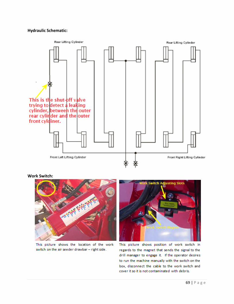
Hydraulic Schematic:
Work Switch:

70 | P a g e
Seed Sensor System:

71 | P a g e
Openers Different types of opener designs and variations have been developed for the various seeds and soil applications. The openers are available in several working widths and can be mounted on the shanks using adapters. For further information contact your local authorized dealer.
Anderson Triple Shoot Opener The Triple Shoot Opener is a combined seeding and fertilizing opener.
AM1085561 AE-15 Dry
This opener is used on a double shoot dry 60-15. It places the fertilizer below the seed and also places starter fertilizer with the seed in paired rows.
AM1085500 Double Reverse Drop Opener
This opener is used for planting legumes, corn and also mid row banding fertilizer between 30” rows on a double shoot 60-15 or 40-15.

72 | P a g e
AM 1085958 AE-15 Liquid Opener w/ Bleed-Off AM1085562 AE-SS w/ Liquid or NH3
* For a complete list of Openers available for different applications, please contact your local authorized Horsch dealer.
This opener is used for planting small grains in 15” paired rows, and corn or beans in 30” paired rows with the NH3 or liquid below the seed.
This opener is used for planting corn or beans in 15” rows and mid banding the NH3 or liquid between 30” rows.

73 | P a g e
Maintenance Maintenance and Service Follow the safety instructions for servicing and maintenance.
Your air seeder has been designed and constructed for maximum performance, operational efficiency and operator friendliness under a wide variety of operating conditions.
Prior to delivery, the machine has been inspected at the factory and the dealership to ensure that you receive an air seeder in optimum condition.
To ensure trouble-free operation, it is important that servicing and maintenance work is performed at the recommended intervals.
Cleaning In order to ensure that the machine is always in operating condition and to achieve optimum performance, perform the cleaning work at regular intervals as well.
IMPORTANT: Do not use high pressure hoses or water jets to clean electrical components such as magnetic valves and seed flow sensors or seals of hydraulic cylinders and wheel hubs. The housing, screwed connections and bearings are not water tight.
• Clean the machine on the outside with water.
Preparation for Storage If you want to store the machine for a longer period, pay attention to the following points:
• Park the machine inside a building if possible. • Empty the distributors completely. • Protect the air seeder against rust. If you want to spray the drilling machine with oil, use only
oils that are easily biodegradable, e.g., rapeseed oil.
Removing from Storage
1. Check tire air pressure and inflate as necessary. 2. Clean the machine thoroughly. 3. Perform required lubrication. See Lubrication and Maintenance in this section. 4. Check all hardware and torque bolts as needed. 5. Review Owner’s Operator Manual, giving special attention to safety precautions.

74 | P a g e
Operator Support Horsch wants you to be completely satisfied with your air seeder. Should you have any problems, please contact your dealer/distributor and Service Technician at any time.
In order for us to process technical requests more quickly, we ask you provide specific information about the machine for a better understanding of the issue to better assist you in customer service.
Help us to avoid having to make unnecessary requests for further information. Always specify the following:
• Customer Number (Dealer provided) • Name of Dealer • Machine Model • Serial Number • Date of Purchase • Operating Hours • Type of Problem
Locate your nearest authorized dealer here, http://www.horsch.com.
Maintenance Schedule Apart from daily maintenance, the intervals are based on the number of operating hours and time.
Keep a record of your operating hours to ensure that the specified maintenance intervals are followed as closely as possible.
Tire Inflation Never use a machine that is due for maintenance. Ensure that all deficiencies found during regular checks are fixed immediately.
Size Bar PSI 395/550-16.5 2.77 60 215/70D15 2.08 60 27 x 8.50-15 2.08 60
Type Brand Series Ply Size Index Rating PSI Caster Firestone Duraforce DT 12 395/55D16.5 F 6835 60 Packer Firestone Farm HF-1 8 27 x 8.50-15 D 1820 60 Packer Firestone Duraforce DT 8 215/70D15 D 2880 60

75 | P a g e
Tightening Wheel Hardware Torque wheel hardware using the following procedure:
IMPORTANT: Wheel bolts must be clean and oil free when torqueing. Torque values specified in the following steps are for clean, dry wheel bolts. Lubricating oil reduces friction and thread bite to overload bolts.
Initial Wheel Bolt Torque Use the tightening sequence shown in the picture attached. Tighten wheel bolts and lug nuts in a crisscross pattern to evenly pull the wheel tight to the hub.
• Caster Wheel Bolts – 150 lbs./ft. • Packer Wheel Bolts – 100 lbs./ft.
Final Wheel Bolt Torque IMPORTANT: Using hand tools and a torque wrench is required. To achieve high torque results, final torqueing must be done with the tire on the ground.
Checking Wheel Attaching Hardware and Bearings Check the tightness of all wheel hardware and wheel bearings during the first week of operation, and every 200 hours thereafter. The spindle nut must be torqued to 65 lbs./ft. Be sure the cotter pin is reinstalled.
To adjust wheel bearings, remove the center wheel cap. Remove the cotter pin. Raise the wheel and turn. Tighten the nut until the wheel has just a slight bit of drag on the bearing. Back off the nut until the next slot of the castle nut lines up with the hole of the spindle. This should be close to 65 lbs./ft. of torque. Insert the cotter pin. Grease the hub bearing once every 200 hours with just a few (2-3) pumps of grease. Do NOT over grease! Replace the wheel center cap.
Lubricants and Hydraulic Oil The hydraulic fluid from the tractor is mixed with the hydraulic fluid from the machine.
The grease points of the seeder can be greased with multi-grade lubricating grease.

76 | P a g e
Perform Lubrication and Maintenance procedures.
Do not clean, lubricate or adjust machine while in motion.
The recommended service intervals are based on normal conditions; severe or unusual conditions may require more frequent lubrication.
Perform each lubrication and service procedure illustrated in this section at the beginning of each season.
Clean grease fittings before using grease gun. Replace any lost or broken fittings immediately. If a new fitting fails to take grease, remove and check for failure of adjoining parts.
Grease
Use grease based on NLGI consistency numbers and the expected air temperature range during the service interval.
The following greases are recommended:
• HD MOLY GREASE • HD LITHIUM COMPLEX GREASE • HD WATER RESISTANT GREASE • GREASE GARD
* Other greases may be used if they meet the following: NLGI Performance Classification GC-LB.
IMPORTANT: Some types of grease thickener are not compatible with others.
IMPORTANT: Grease is used to lubricate wheel bearings. Recommended maintenance for grease lubricated wheel bearings is every 200 hours, using Multipurpose High Temperature EP Grease.

77 | P a g e
Walking Tandem Adjustment Walking tandems should occasionally be adjusted by using the wrenches supplied, located on the front hitch of the machine.
Loosen jam nut A and tighten jam nut B until there is a slight drag applied to the tandem. Then retighten the jam nut A to jam nut B.

78 | P a g e
Hitch Adjustment & Maintenance The front hitch of a seed wagon has a few options for hitching to the rear hitch of a planting system. There are typical Thru-Hole Drop Pin type hitches, and Ball Head type hitches.
The Thru-Hole type will not require any adjustment or maintenance, except height location desired based on planting system.
The Ball Head type hitches do require some adjustment and maintenance. First you must identify the two types of available ball type hitches.
PN 00340446 – Ball Coupling, CPL. 80MM PN 95120740 – Ball Coupling, 80MM –
Pivoting Flanged Follow the adjustment and maintenance procedures below in regards to the ball head type couplings.
Adjustment:
It is mandatory to carry out and regularly check the adjustment of the hold-down of the ball head coupling prior to each use.
Adjust hold-down assembly to 0.5mm (0.020”) Use a sheet of standard white paper or a feeder gauge.

79 | P a g e
1. Remove the circlips and pins (A) of the hold-down securing it to the casting. 2. Remove the hold-down assembly (B) from the ball carrier casting. 3. By turning the adjusting screw (C) adjust the height of the hold-down as necessary. 4. Reinsert the hold-down in to the ball carrier. 5. Move the hold-down over the ball coupling (D) and secure it with the hold-down pins and
circlips.
IMPORTANT! AVOID DAMAGE. THE HOLD-DOWN MUST NOT BE SET TOO TIGHT! THERE SHOULD ALWAYS BE A PRECISE SPACING OF 0.5MM (0.020”) BETWEEN THE HOLD-DOWN AND THE TRAILER HITCH BALL COUPLING.
Maintenance:
Foam Ring Lubrication
Keep foam ring intact as a dust filter. Apply grease to ball and trailer hitch regularly.

80 | P a g e
Maintenance Schedule
After First Operation Instructions Interval Check all hardware Tighten if necessary Lubricate Air Seeder See Overview of Lubricating Points Before Each Operation Instructions Interval Lubricate Air Seeder See Overview of Lubricating Points Raise Seeder to top position several times Balance hydraulic cylinders (height adjustment) daily Upper Links Tighten if necessary daily Coupling of Drawbar Ensure bolts are firmly tight daily Depth adjustment basic position Check by lowering to 3/8" above the ground (flat surface) daily Hydraulic lines and components Check seals, function and condition&check for crushing/chafing daily Seed Hoses Check daily Coulters &Leveling Disc Check condition&wear daily Distributor, Distributor Lid Check for blockages daily Road Lighting Check condition and function daily
Grab Swing Brake on Swivel Caster Wheels Check function and setting Every 50 hrs. Check condition and wear Every 50 hrs.
Check Air Pressure Packer: 30PSI weekly Caster Wheels: 40 PSI weekly
Wheel Bearings on Packer Check condition and make sure it is firmly seated. Torque to 60 ft./lbs.
before season
Bearings on Caster Wheels Check condition, adjust bearings. Grease wheel bearings
before season/ 200 hrs.
After Season Instructions Interval Electrical control devices (Drill Manager, GPS) Store in a dry place Entire Machine Carry out cleaning and maintenance Spray Drill machine with oil Use biological oil if possible After 3 -5 years Instructions Interval Hydraulic Hoses on Hydraulic Cylinders Replace

81 | P a g e
Overview of Lubricating Points
Grease Point Description Quantity Interval 1 Front Hitch Pivot Pin 2 Daily 2 Folding Pins on Inner Wings 4 Daily 3 Caster Axle 1 each Daily 4 Caster Wheel Spindle/Hub Bearing 1 each 200 Hrs. Packer Wheel Spindle/Hub Bearing 1 each 100 Hrs.
5 Front Caster Parallel Arm Pivot Pins 4 each Daily 6 Caster Tower 1 each Daily 7 Folding Pins on Outer Wings 4 Daily 8 Front Distributor Lift Parallel Arm Pivot Pins 4 100 Hrs. 9 Rear Drawbar Pins 2 100 Hrs.
10 Packer Pivot Pins 1 each 100 Hrs. 11 Cutting Coulter Disc hub 1 each Daily 12 Cutting Coulter Shank 1 each Daily
Front Hitch Pivot pins (x2)
Wing pivot pins (Inner & Outer) (x8 – Panther 460, x4 – Panther 440)
Lower Front Distributor Lift Pin (x2)

82 | P a g e
Caster Axle (x1 per axle)
Spindle Hub (x1 per axle – Caster & Packer)
Parallel Caster Pivot Arms (x4 per Caster)
Caster Tower (x1 per Caster)

83 | P a g e
Rear Drawbar Pins (x2)
Packer system pivot pins (x1 per packer)
Cutting Coulter Disc & Shank (x1 each)

84 | P a g e
Lubricating the Machine Please read the section below entitled ‘Handling of Lubricants’ carefully before lubricating the machine.
The machine must be greased regularly in order for it to remain serviceable. Regular greasing also contributes towards extending the service life of the machine.
The recommended service intervals are specified above.
Upon cleaning the machine, it is important to lubricate the machine as well to ascertain no moisture is held inside bearings and other grease points that may contribute to deterioration and rust.
Handling Lubricants Please ensure that you read the following instructions as well as the relevant information. This also applies to any users of this machine or who may come in contact with the machine.
Hygiene In the case of prolonged skin contact, lubricants, especially low-viscosity oils, may remove the natural layer of fat contained in the skin, resulting in dryness and possible irritation.
It is important to take extreme care when handling waste oil as it may contain other irritants.
Vapors given off by cleaning agents and oils are also a potential health hazard. Therefore, you should not carry any oily cloths around. Change soiled clothing as soon as possible.
Always exercise extreme care and observe the recommended hygiene rules when handling mineral oil products.
Storage and Handling • Always store lubricants where they cannot be accessed by children. • Never store lubricants in open or unlabeled containers.
Fresh Oil: Apart from taking the usual care and observing hygiene rules, there is no need to take any special precautions when handling fresh oil.
Waste Oil: Waste oil can contain harmful contaminations which may cause skin cancer, allergies and other illnesses.
• Wash your skin thoroughly with soap and water. • Use special cleaning agents to clean any dirt off
your hands. • Never wash oil residue from your skin with
petrol, diesel fuel or paraffin. • Avoid skin contact with any oily clothing. • Do not keep any oil rags in your pockets. • Wash soiled clothing before wearing it again. • Ensure that any oil footwear is disposed of in the
proper manner.

85 | P a g e
Troubleshooting When troubleshooting and performing diagnostics, remember to follow the safety instructions and be aware of all posted warning and caution labels.
The following charts are intended to enable you to quickly remedy any malfunctions. If you are unable to find a particular malfunction in the charts, contact your nearest authorized Horsch dealer for further assistance and customer service.

86 | P a g e
Service & Information Metric Bolt & Screw Torque Values

87 | P a g e
Unified Bolt & Screw Torque Values
Do not use these values if different torque value or tightening procedure is given for a specific application. Torque values listed are for general use only. Check tightness of fasteners periodically. Refer to the Maintenance Schedule listed in this manual on the previous pages.
Shear bolts are designed to fail under predetermined loads. Always replace a shear bolt with identical property class.

88 | P a g e
Fasteners should be replaced with the same or higher property class. If higher property class fasteners are used, these should only be tightened to the strength of the original.
Make sure fastener threads are clean and that you properly start thread engagement. This will prevent them from failing and cross threading when tightening.
Tighten plastic inserts or crimped steel-type lock nuts to approximately 50% of the dry torque shown in the chart, applied to the nut, not the bolt head. Tighten serrated-type lock nuts to the full torque value.
Metric Conversions To convert from standard to metric measurements, multiply by the following factors:

89 | P a g e
Hydraulic Schematic – Lift (ATD 60-15/Panther 460 shown)
Item 32 is a filter screen used to prevent foreign material from entering the hydraulic system of the air seeder. If the air seeder starts to raise and lower at a slower rate than normal rate, this screen could be plugged and should be removed and cleaned thoroughly.

90 | P a g e
Hydraulic Schematic – Fold (ATD 60-15/Panther 460 shown)

91 | P a g e
Cylinder Rod Maintenance PRP (Piston Rod Protection)
Chrome plated piston rod and bar products normally contain a minimum of 20 microns to 50 microns hard chrome plate, depending upon the product specifications. This hard chrome plating is applied primarily for wear resistance, though it does considerable corrosion resistance as well. Once the shaft is assembled into a cylinder and put into service, the hydraulic fluid on the surface provides additional corrosion resistance that is normally sufficient to protect the shaft during its entire life. However, there are occasions when the shaft is not being worked and when the surface is exposed to a corrosive environment. For example, brand new equipment may be stored outside for a considerable period of time from the manufacturing plant or the dealer, and may hold as inventory until sold. In these instances, it is best recommended to provide some additional corrosion protection. An inexpensive application of PRP can be applied to prevent corrosion and thereby preserve the quality of the hard chrome plated piston rod.
Protection of the cylinder rod is important. If the rod was to be damaged or pitted it will damage the wiper seal of the cylinder housing and create a leak in the system. Taking the necessary precautions of preventative maintenance will ensure a longer life of the machine.
Protection of new equipment: The steps summarized below should be followed when protecting chrome plate shafting on new equipment.
• Position the equipment as it will be stored, and identify all the exposed portions of the chrome plated shafts.
• Clean dirt and dust from the exposed portions of the shafts using a dry cloth. • Apply a thin coating of PRP mixture to the exposed surfaces of the chrome shaft. Depending on
the type of PRP used, it can be applied directly to the shaft either by spray or rubbed on to the surface.
• Inspect the shaft surface after 5 month and apply additional corrosion protection PRP. • If the equipment is to be moved and then stored again for an extended period of time, the steps
above should be repeated for all shafts that were stroked or cycled during the move.
Protection of older equipment: • Occasionally it might be necessary to store some equipment that has seen some service. The
procedure described above can be useful, but more careful cleaning of the shaft surface should be taken into consideration. If there are any damaged areas to the shaft further attention will be required.
• Under no circumstances should sandpaper or other abrasive materials be used to clean the shaft, however, plastic or copper wool may be used.
• After the surface is clean, it should be inspected for damages to the chrome plate. If damage is detected, more frequent application of PRP will be necessary to prevent corrosion during storage.

92 | P a g e
Protect Your Hydraulic Cylinders from Rust Many types of equipment have hydraulic cylinders. A hydraulic cylinder is a piston that slides within a cylindrical body. A rod attached to the piston passes through a seal at the end of the cylindrical body and moves in and out to do useful work. The rods on most hydraulic cylinders are highly polished plated steel. They must be uniformly smooth to provide a good seal with the cylinder body.
A common problem with hydraulic cylinders is rust and pitting of the cylinder rods (Figure 1). If equipment that incorporates hydraulic cylinders is stored outside with the cylinder rods extended, the rods are exposed to weathering. Eventually, the rods will begin to show specks of rust that develop into pits. Once rusting and pitting occur, the rod will destroy the cylinder seal the next time it is activated. Once pitted, it is virtually impossible to restore a cylinder rod to an acceptably smooth condition through repolishing.
This problem of cylinder-rod pitting is most common with hydraulic cylinders on equipment that is both stored outside and seldom used or used only seasonally. If the hydraulic cylinders are operated every few days, the rods will always have a thin coating of oil that will provide protection, and rust will not start. Good examples are backhoes and bulldozers that are always stored out in the weather but are used almost daily.
The solution to this problem is to prevent rust and pitting. There are three ways to accomplish this, and it is possible to use more than one of these approaches simultaneously. The best way to avoid corrosion and pitting of the cylinder rods is to store the implement with the cylinder rods retracted. If the rods are retracted, the sensitive plated surface of the rod will be inside the cylinder, immersed in hydraulic fluid and thus fully protected. Unfortunately, it is not always possible to store equipment with the cylinders retracted. In some cases, the cylinders must be extended to unhitch an implement or must be extended to park the equipment. Another way to reduce the chance of corrosion is to park equipment with hydraulic cylinders inside a building where the cylinders are protected. This will significantly reduce corrosion and pitting, although humidity and condensation can still occur in some storage sheds. A final method of protecting cylinders is somewhat less effective but can be used in all situations. The exposed cylinder rods can be coated with heavy grease whenever the equipment will not be used for a few weeks or longer (Figure 2). The grease should be as heavy and sticky (tacky) as possible. Wheel bearing grease is better for this purpose than general chassis grease because it tends to be tackier. A heavy coat of grease will provide several months of protection, but for a machine used only one season a year, it may be necessary to renew the grease every three to four months.
Hydraulic cylinders can be ruined by pit rust if left extended and not protected. They are expensive to replace. You can protect your cylinders by (a) storing them in a retracted position, (b) storing them inside or (c) coating any exposed portion of the rods with heavy grease.

93 | P a g e
Notes:
Go to Top

94 | P a g e
HORSCH, LLC * 200 Knutson St. Mapleton, ND 58059 USA * 701.532.1000 * [email protected] * www.horsch.com
PN 05200200 Ver. 6 02/2016